

Sony HVO-500MD,HVO-550MD Instructions For Use Manual

4-564-082-11 (1)
HD Video Recorder
Instructions for Use
Before operating the unit, please read this manual thoroughly
and retain it for future reference.
HVO-500MD/550MD
© 2014 Sony Corporation
Caution
Federal law (United States of America) restricts this device
to sale by or on the order of a licensed healthcare
practitioner.
Owner’s Record
The model and serial numbers are located at the rear.
Record these numbers in the space provided below.
Refer to these numbers whenever you call upon your Sony
dealer regarding this product.
Model No. ____________________
Serial No. ____________________
WARNING
To reduce the risk of fire or electric shock, do not
expose this apparatus to rain or moisture.
To avoid electrical shock, do not open the
cabinet. Refer servicing to qualified personnel
only.
No modification of this equipment is allowed.
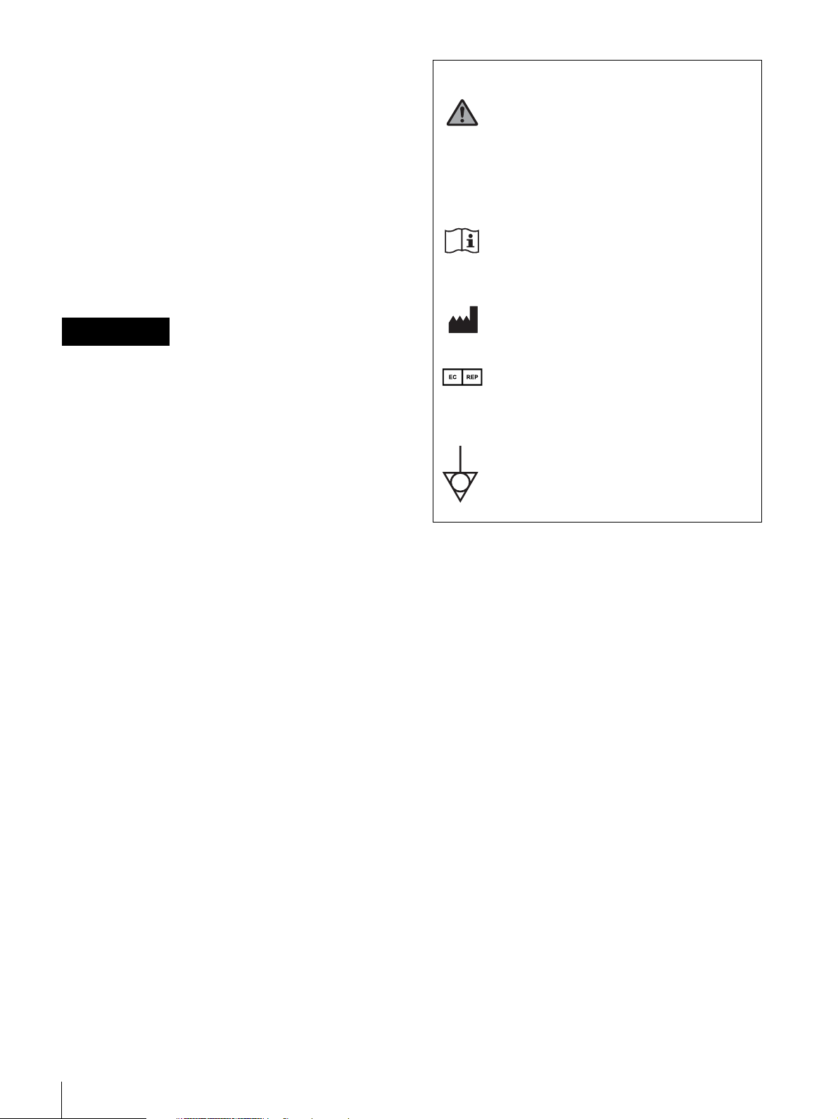
Symbols on the products
General warning sign
Follow the warnings in the Instructions for
Use for parts of the unit on which this mark
appears.
NOTE Background colour: Yellow
Triangular band: Black
Symbol: Black
Consult the Instructions for Use
Follow the directions in the Instructions for
Use for parts of the unit on which this mark
appears.
This symbol indicates the manufacturer, and
appears next to the manufacturer’s name and
address.
This symbol indicates the European
Community representative, and appears next
to the European Community representative’s
name and address.
This symbol indicates the equipotential
terminal which brings the various parts of a
system to the same potential.
Caution
For HVO-550MD
Use of controls or adjustments or performance of
procedures other than those specified herein may result in
hazardous radiation exposure.
For HVO-550MD
This HD Video Recorder is classified as a CLASS 1
LASER PRODUCT.
Caution
For HVO-550MD
The use of optical instruments with this product will
increase eye hazard.
IMPORTANT
The nameplate is located on the bottom.
CAUTION
Do not install the appliance in a confined space, such as
book case or built-in cabinet.
WARNING
Excessive sound pressure from earphones and headphones
can cause hearing loss.
In order to use this product safely, avoid prolonged
listening at excessive sound pressure levels.
For the customers in the U.S.A.
This equipment has been tested and found to comply with
the limits for a Class B digital device, pursuant to part 15
of the FCC Rules. These limits are designed to provide
reasonable protection against harmful interference in a
residential installation. This equipment generates, uses and
can radiate radio frequency energy and, if not installed and
used in accordance with the instructions, may cause
harmful interference to radio communications. However,
there is no guarantee that interference will not occur in a
particular installation. If this equipment does cause
harmful interference to radio or television reception, which
can be determined by turning the equipment off and on, the
user is encouraged to try to correct the interference by one
or more of the following measures:
- Reorient or relocate the receiving antenna.
- Increase the separation between the equipment and
receiver.
2

- Connect the equipment into an outlet on a circuit
different from that to which the receiver is connected.
- Consult the dealer or an experienced radio/TV
technician for help.
You are cautioned that any changes or modifications not
expressly approved in this manual could void your
authority to operate this equipment.
All interface cables used to connect peripherals must be
shielded in order to comply with the limits for a digital
device pursuant to Subpart B of part 15 of FCC Rules.
If you have any questions about this product, you may call;
Sony Customer Information Service Center 1-800-2227669 or http://www.sony.com/
4. For this particular equipment, all accessory equipment
connected as noted above, must be connected to mains
via an additional isolation transformer conforming with
the construction requirements of IEC60601-1 and
providing at least Basic Insulation.
5. This equipment generates, uses, and can radiate radio
frequency energy. If it is not installed and used in
accordance with the instruction manual, it may cause
interference to other equipment. If this unit causes
interference (which can be determined by unplugging
the power cord from the unit), try these measures:
Relocate the unit with respect to the susceptible
equipment. Plug this unit and the susceptible
equipment into different branch circuit.
Declaration of Conformity
Trade Name : SONY
Model : HVO-500MD/550MD
Responsible party : Sony Electronics Inc.
Address : 16530 Via Esprillo, San Diego,
CA 92127 U.S.A.
Telephone Number : 858-942-2230
This device complies with part 15 of the FCC Rules.
Operation is subject to the following two conditions:
(1) This device may not cause harmful interference,
and (2) this device must accept any interference
received, including interference that may cause
undesired operation.
For the customers in Canada
CAN ICES-3 (B)/NMB-3(B)
This unit has been certified according to Standard CAN/
CSA-C22.2 No.60601-1.
Important safeguards/notices for use in the
medical environments
1. All the equipments connected to this unit shall be
certified according to Standard IEC60601-1,
IEC60950-1, IEC60065 or other IEC/ISO Standards
applicable to the equipments.
Consult your dealer. (According to standard IEC60601-1-2
and CISPR11, Class B, Group 1)
2. Furthermore all configurations shall comply with the
system standard IEC60601-1-1. Everybody who
connects additional equipment to the signal input part
or signal output part configures a medical system, and
is therefore, responsible that the system complies with
the requirements of the system standard IEC60601-1-1.
If in doubt, consult the qualified service personnel.
3. The leakage current could increase when connected to
other equipment.
3
Important EMC notices for use in the medical environments
• The HVO-500MD/550MD needs special precautions regarding EMC and needs to be installed and put into service
according to the EMC information provided in this Instructions for Use.
• The portable and mobile RF communications equipment such as cellular phones can affect the HVO-500MD/550MD.
Warning
The use of accessories and cables other than those specified, with the exception of replacement parts sold by Sony
Corporation, may result in increased emissions or decreased immunity of the HVO-500MD/550MD.
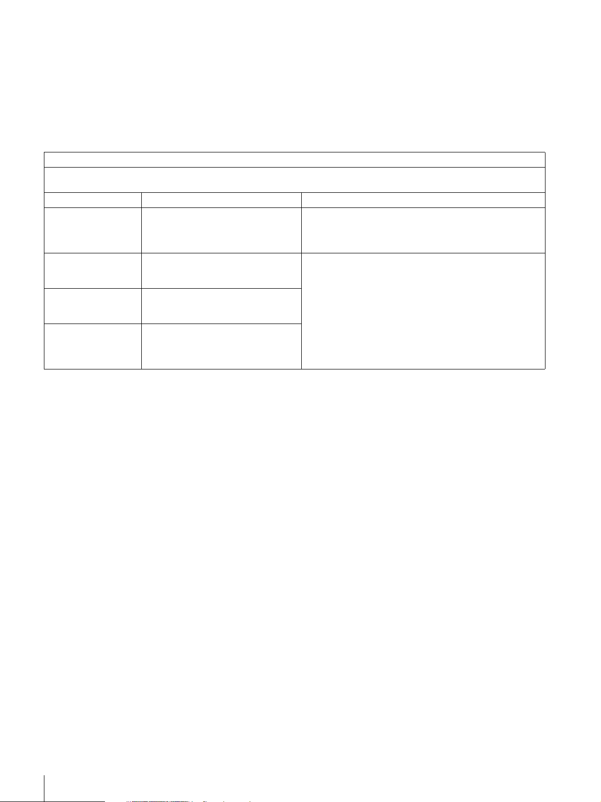
Guidance and manufacturer’s declaration-electromagnetic emissions
The HVO-500MD/550MD is intended for use in the electromagnetic environment specified below.
The customer or the user of the HVO-500MD/550MD should assure that it is used in such an environment.
Emission test Compliance Electromagnetic environment-guidance
RF emissions
CISPR 11
RF emissions
CISPR 11
Harmonic emissions
IEC 61000-3-2
Voltage fluctuations/
flicker emissions
IEC 61000-3-3
Group 1
Class B
Not applicable
Not applicable
The HVO-500MD/550MD uses RF energy only for its
internal function. Therefore, its RF emissions are very low
and are not likely to cause any interference in nearby
electronic equipment.
The HVO-500MD/550MD is suitable for use in all
establishments, including domestic establishments and
those directly connected to the public low-voltage power
supply network that supplies buildings used for domestic
purposes.
WAR N ING
If the HVO-500MD/550MD should be used adjacent to or stacked with other equipment, it should be observed to verify
normal operation in the configuration in which it will be used.
4
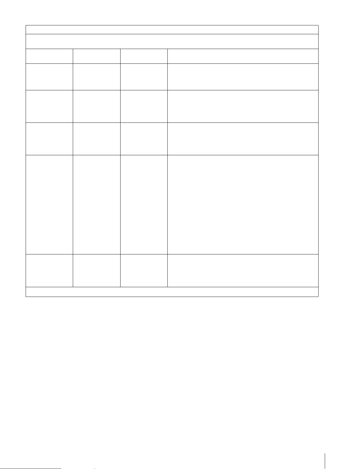
Guidance and manufacturer’s declaration - electromagnetic immunity
The HVO-500MD/550MD is intended for use in the electromagnetic environment specified below. The customer or the user
of the HVO-500MD/550MD should assure that it is used in such as environment.
Immunity test
Electrostatic
discharge (ESD)
IEC 60601 test
level
±6 kV contact
Compliance level Electromagnetic environment-guidance
±6 kV contact
Floors should be wood, concrete or ceramic tile. If floors are
covered with synthetic material, the relative humidity should be
at least 30%.
IEC 61000-4-2
Electrical fast
transient/burst
±8 kV air
±2 kV for power
supply lines
±8 kV air
Mains power quality should be that of a typical commercial or
hospital environment.
IEC 61000-4-4
Surge
IEC 61000-4-5
Voltage dips, short
interruptions and
voltage variations
on power supply
input lines
IEC 61000-4-11
Power frequency
(50/60 Hz)
magnetic field
IEC 61000-4-8
NOTE: U
is the a.c. mains voltage prior to application of the test level.
T
±1 kV for input/
output lines
±1 kV line(s) to
line(s)
±1 kV for input/
output lines
Not applicable Mains power quality should be that of a typical commercial or
hospital environment.
±2 kV line(s) to
earth
< 5% U
T
(> 95% dip in UT)
for 0.5 cycle
40% U
T
Not applicable Mains power quality should be that of a typical commercial or
hospital environment. If the user of the HVO-500MD/550MD
requires continued operation during power mains interruptions,
it is recommended that the HVO-500MD/550MD be powered
from an uninterruptible power supply or a battery.
(60% dip in UT)
for 5 cycles
70% U
T
(30% dip in UT)
for 25 cycles
< 5% U
T
(> 95% dip in UT)
for 5 sec
3 A/m 3 A/m Power frequency magnetic fields should be at least
characteristic of a typical location in a typical commercial or
hospital environment.
5
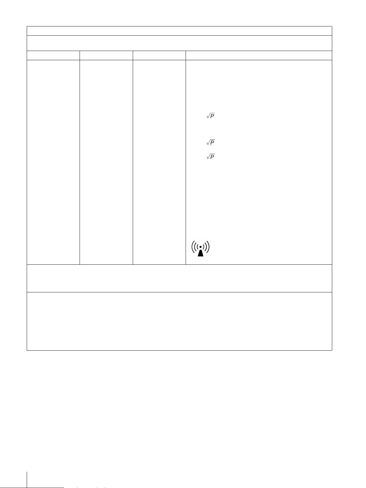
Guidance and manufacturer’s declaration - electromagnetic immunity
The HVO-500MD/550MD is intended for use in the electromagnetic environment specified below. The customer or the user
of the HVO-500MD/550MD should assure that it is used in such as environment.
Immunity test IEC 60601 test level Compliance level Electromagnetic environment-guidance
Portable and mobile RF communications equipment
should be used no closer to any part of the HVO-500MD/
550MD, including cables, than the recommended
separation distance calculated from the equation
appliance to the frequency of the transmitter.
Recommended separation distance
Conducted RF
IEC 61000-4-6
Radiated RF
IEC 61000-4-3
NOTE 1: At 80 MHz and 800 MHz, the higher frequency range applies.
NOTE 2: These guidelines may not apply in all situations. Electromagnetic propagation is affected by absorption and
reflection from structures, objects and people.
a Field strengths from fixed transmitters, such as base stations for radio (cellular/cordless) telephones and land mobile
radios, amateur radio, AM and FM radio broadcast and TV broadcast cannot be predicted theoretically with accuracy.
To assess the electromagnetic environment due to fixed RF transmitters, an electromagnetic site survey should be
considered. If the measured field strength in the location in which the HVO-500MD/550MD is used exceeds the applicable
RF compliance level above, the HVO-500MD/550MD should be observed to verify normal operation. If abnormal
performance is observed, additional measures may be necessary, such as reorienting or relocating the HVO-500MD/
550MD.
3 Vrms
150 kHz to 80 MHz
3 V/m
80 MHz to 2.5 GHz
3 Vrms
3 V/m
d = 1.2
d = 1.2 80 MHz to 800 MHz
d = 2.3 800 MHz to 2.5 GHz
Where P is the maximum output power rating of the
transmitter in watts (W) according to the transmitter
manufacturer and d is the recommended separation
distance in meters (m).
Field strengths from fixed RF transmitters, as determined
by an electromagnetic site survey, a should be less than
the compliance level in each frequency range.
Interference may occur in the vicinity of equipment marked
with following symbol:
b
b Over the frequency range 150 kHz to 80 MHz, field strengths should be less than 3 V/m.
6
Recommended separation distances between portable and mobile RF communications equipment and the
The HVO-500MD/550MD is intended for use in an electromagnetic environment in which radiated RF disturbances are
controlled. The customer or the user of the HVO-500MD/550MD can help prevent electromagnetic interference by
maintaining a minimum distance between portable and mobile RF communications equipment (transmitters) and the
HVO-500MD/550MD as recommended below, according to the maximum output power of the communications equipment.
Rated maximum output power of transmitter
W
0.01 0.12 0.12 0.23
0.1 0.38 0.38 0.73
1 1.2 1.2 2.3
10 3.8 3.8 7.3
100 12 12 23
For transmitters rated a maximum output power not listed above, the recommended separation distance d in meters (m) can
be estimated using the equation applicable to the frequency of the transmitter, where P is the maximum output power rating
of the transmitter in watts (W) according to the transmitter manufacturer.
NOTE 1: At 80 MHz and 800 MHz, the separation distance for the higher frequency range applies.
HVO-500MD/550MD
Separation distance according to frequency of transmitter
150 kHz to 80 MHz
d = 1.2
80 MHz to 800 MHz
m
d = 1.2
800 MHz to 2.5 GHz
d = 2.3
NOTE 2: These guidelines may not apply in all situations. Electromagnetic propagation is affected by absorption and
reflection from structures, objects and people.
CAUTION
When you dispose of the unit or accessories, you must obey the laws in the relative area or country and the regulations in
the relative hospital.
For the customers in Europe
This product has been manufactured by or on behalf of Sony Corporation, 1-7-1 Konan Minato-ku Tokyo, 108-0075 Japan.
Inquiries related to product compliance based on European Union legislation shall be addressed to the authorized
representative, Sony Deutschland GmbH, Hedelfinger Strasse 61, 70327 Stuttgart, Germany.
For any service or guarantee matters, please refer to the addresses provided in the separate service or guarantee documents.
For the State of California, USA only
Perchlorate Material - special handling may apply, See www.dtsc.ca.gov/hazardouswaste/perchlorate
For the customers in Taiwan only
For the customers in the U.S.A.
SONY LIMITED WARRANTY
http://www.sony.com/psa/warranty
warranty applicable to this product.
- Please visit
for important information and complete terms and conditions of Sony’s limited
For the customers in Canada
SONY LIMITED WARRANTY
http://www.sonybiz.ca/solutions/Support.do
- Please visit
for important information and complete terms and conditions of Sony’s
limited warranty applicable to this product.
For the customers in Europe
Sony Professional Solutions Europe - Standard Warranty and Exceptions on Standard Warranty.
Please visit http://www.pro.sony.eu/warranty
for important information and complete terms and conditions.
For the customers in Korea
SONY LIMITED WARRANTY
http://bpeng.sony.co.kr/handler/BPAS-Start
- Please visit
for important information and complete terms and conditions of Sony’s
limited warranty applicable to this product.
7

Table of Contents
Please Read First...........................................................................12
Usage Notes ...................................................................................13
Chapter 1 Overview
Features..........................................................................................14
System Configuration Example....................................................15
Names and Functions of Parts .....................................................16
Chapter 2 Preparation
Connections ...................................................................................21
Turning the Unit On and Off .........................................................21
Configuring System Settings .......................................................22
Configuring Recording Settings (User Settings)........................23
Using the On-Screen Keyboard (Text Entry)...............................29
Handling Discs...............................................................................30
Function Keys ................................................................................32
Front .................................................................................................... 16
Rear ..................................................................................................... 18
Displaying the [User Settings] Screen................................................. 23
Configuring Input Signal Settings....................................................... 23
Configuring Image Quality Settings.................................................... 24
Configuring Save Settings................................................................... 26
Configuring Print Settings................................................................... 27
Names and Functions of Parts (On-Screen Keyboard) ....................... 29
Notes on Handling............................................................................... 30
Inserting and Removing Discs ............................................................ 31
Using Function Keys ........................................................................... 32
Factory Assigned Functions ................................................................ 33
Other Assignable Functions ................................................................ 33
8
Table of Contents

Chapter 3 Basic Recorder Operations
Operation Flow...............................................................................34
Step 1 Record.................................................................................34
Step 2 Quick Playback ..................................................................35
Step 3 Capture Still Images ..........................................................36
Step 4 Stop Recording ..................................................................37
Chapter 4 Recording and Playback
Recording .......................................................................................38
Manual Recording ............................................................................... 38
Capturing Still Images...................................................................40
Manual Still Image Capture ................................................................ 40
Stopping Recording Operations ..................................................41
Manual Recording Stop....................................................................... 41
Stopping Recording to External Media and Automatic Printing ........ 41
Playback .........................................................................................42
Playing Back the Most Recent Data (Quick Playback)....................... 42
Recording Preparation ..................................................................43
Patient Information and Data Storage Settings ................................... 43
Using a Hard Keyboard for Patient Information and Data Storage
Settings....................................................................................... 45
Registering Multiple Patients in Advance........................................... 46
Test Recording .................................................................................... 48
Image Search .................................................................................49
Specifying Search Conditions ............................................................. 49
Viewing Thumbnails of Recorded Data.............................................. 50
Playback from the Search Results List................................................ 51
Sorting the Recorded Data List ........................................................... 52
Processing Recorded Data...........................................................53
Printing ................................................................................................ 53
Copying to External Media ................................................................. 55
Editing Patient Information ................................................................. 58
Protecting Recorded Data.................................................................... 59
Deleting Recorded Data ...................................................................... 60
Viewing Information on Recorded Data ............................................. 61
Table of Contents
9

Chapter 5 System Administrator Settings
Overview.........................................................................................63
Displaying the [System Admin Settings] Screen........................63
Language Settings.........................................................................64
Date and Time Settings .................................................................65
Function Settings ..........................................................................68
[General 1] Tab ................................................................................... 68
[General 2] Tab ................................................................................... 69
[Video 1] Tab ...................................................................................... 73
[Video 2] Tab ...................................................................................... 75
Device Settings..............................................................................76
[Device] Tab........................................................................................ 76
[Contact Switch] Tab........................................................................... 79
Password Settings.........................................................................82
Network Settings ...........................................................................83
[Network] Tab ..................................................................................... 83
[File Server] Tab ................................................................................. 85
[NTP] Tab............................................................................................ 85
Initial User Settings .......................................................................87
[Quality] Tab ....................................................................................... 87
[Save] Tab ........................................................................................... 88
Editing the Doctor List ..................................................................90
Registering Doctor Information .......................................................... 90
[General] Tab ...................................................................................... 91
[File Server] Tab ................................................................................. 91
[Print] Tab ........................................................................................... 92
Sorting the Doctor List ........................................................................ 93
Editing Doctor Information ................................................................. 93
Deleting Doctor Entries....................................................................... 93
Editing the Case List .....................................................................94
Registering Categories ........................................................................ 94
Sorting the Category List .................................................................... 95
Editing Category Names ..................................................................... 95
Deleting Categories ............................................................................. 95
Registering Cases ................................................................................ 96
Sorting the Case List ........................................................................... 97
Editing Case Names ............................................................................ 97
Deleting Cases..................................................................................... 97
Auto Delete Settings......................................................................98
10
Table of Contents

Chapter 6 Miscellaneous
Error Messages..............................................................................99
Troubleshooting ..........................................................................101
Licenses .......................................................................................102
Specifications ..............................................................................103
Index ............................................................................................105
DCMTK............................................................................................. 102
gSOAP............................................................................................... 102
Live555 Streaming Media ................................................................. 102
libjpeg................................................................................................ 102
LibTIFF ............................................................................................. 102
zlib ..................................................................................................... 102
Trademarks
• The terms HDMI and HDMI High-Definition Multimedia Interface, and the HDMI Logo are trademarks or registered
trademarks of HDMI Licensing LLC in the United States and other countries.
• The products or system names appearing in this document are trademarks or registered trademarks of their respective
owners.
Further, the ® or ™ symbols are not used in the text.
• Reproduction or duplication, in whole or part, of the software or operation manual supplied with the recorder, as well
as renting or leasing of the software without the authorization of the right holder is prohibited under copyright law.
• Sony assumes no responsibility for damages, loss of income, or any claims from a third party arising out of use of
the recorder or supplied software.
• For complete terms and conditions of the warranty for the recorder, refer to the warranty card included in the package.
• The software supplied with the recorder cannot be used with any other recorders.
• It is not possible to install any software into the equipment other than the software supplied by Sony specifically for
use with the equipment.
• Note that the specifications of the recorder and supplied software are subject to change for improvement without
prior notice.
Table of Contents
11

Please Read First
Copyright
Using this unit for video and/or audio recording, or
distribution over the network or otherwise may in some
cases require the permission of the copyright holder of the
video or audio. To protect copyright, observe the following
points carefully when using this unit.
• When connecting a recording device to this and
recording video or audio, carefully observe laws relating
to copyright.
• Without the permission of the copyright holder, the
showing or distribution of video or audio material of
which the copyright is held by a third party, or the act of
recording on the hard disk of this unit, sharing folders,
and permitting of access to a private group or to the
public is prohibited by law.
• With a software upgrade or functional extension, with
the object of protecting copyright, the specifications for
the video and audio signals that can be input may be
changed without notice.
• Under copyright law, you may not use recorded video or
audio other than for your personal enjoyment without the
permission of the copyright holder. Note that at live
performances, shows and exhibitions, even for your
personal entertainment shooting may be restricted.
Disclaimer of Liability for Recorded Data
Sony Corporation does not accept any liability whatsoever
for any problems arising from a failure to record, or from
damage or erasure of recorded content on this equipment,
for any reason. This includes claims for compensation of
recorded content, and for any concomitant and
consequential damages. Sony Corporation will not repair,
restore, or duplicate any recorded content. Your use of this
product is subject to these conditions.
Problems may occur if you perform the following
operations:
• When you use a disc recorded using another DVD
recorder or DVD drive of a personal computer with this
unit. Additional recording to discs recorded using other
DVD recorders or computers is not supported.
On security
SONY WILL NOT BE LIABLE FOR DAMAGES OF
ANY KIND RESULTING FROM A FAILURE TO
IMPLEMENT PROPER SECURITY MEASURES ON
TRANSMISSION DEVICES, UNAVOIDABLE DATA
LEAKS RESULTING FROM TRANSMISSION
SPECIFICATIONS, OR SECURITY PROBLEMS OF
ANY KIND.
On moisture condensation
If the unit is suddenly taken from a cold to a warm location,
or if ambient temperature suddenly rises, moisture may
form on the outer surface of the unit and/or inside of the
unit. This is known as condensation. If condensation
occurs, turn off the unit and wait until the condensation
clears before operating the unit. Operating the unit while
condensation is present may damage the unit.
On consumable parts
• The HDD, fan, battery, and DVD drive are consumable
parts that will need periodic replacement. When
operating at room temperature, a normal replacement
cycle will be about 2 to 3 years.
However, this replacement cycle represents only a
general guideline and does not imply that the life
expectancy of these parts is guaranteed. For details on
parts replacement, contact your dealer.
• The life expectancy of the AC adapter and the
electrolytic capacitor is about 5 years under normal
operating temperatures and normal usage (8 hours per
day; 25 days per month). If usage exceeds the above
normal usage frequency, the life expectancy may be
reduced correspondingly.
Precautions for products with built-in HDD
This unit has a built-in hard disk drive (HDD). The HDD
is a precision device. If subject to shock, vibration, static
electricity, high temperature or humidity, data loss can
occur. When installing and using the unit, closely observe
the following precautions.
Protect from shocks and vibrations
When subject to shocks or vibrations, the HDD can be
damaged and loss of data on the HDD can occur.
• When transporting the unit, use the specified packing
material. When transporting on a dolly or similar, use a
type which does not transmit excessive vibrations.
Excessive shocks and vibrations can damage the HDD.
• Never move the unit while it is powered.
• Do not remove panels or outer parts of the unit.
• When placing the unit on a floor or other surface, make
sure that the unit is equipped with the specified rubber
feet, and put the unit down carefully. If there are no feet,
mount the rubber feet first.
• Do not place the unit near other devices that may become
a source of vibrations.
Wait for 30 seconds after turning power off
For a brief interval after the power is turned off, the platters
inside the HDD will still keep spinning and the heads will
be in an insecure position. During this interval, the unit is
more susceptible to shocks and vibrations than during
normal operation. For a period of at least 30 seconds after
turning power off, avoid subjecting the unit even to very
12
Please Read First

light shocks. After this period, the hard disk will be fully
stopped and the unit can be manipulated.
Temperature and humidity related precautions
Use and store the unit only in locations where the specified
temperature and humidity ranges are not exceeded. (Be
sure to use the unit that conforms fully to the specifications
of this unit.)
When HDD seems to be faulty
Even if the HDD is showing signs of malfunction, be sure
to observe all the above precautions. This will prevent
further damage from occurring until the problem can be
diagnosed and corrected.
Replacement of the HDD and other consumable
parts
The HDD and battery are consumable parts that will need
periodic replacement. When operating at room
temperature, a normal replacement cycle will be about two
to three years. However, this replacement cycle represents
only a general guideline and does not imply that the life
expectancy of these parts is guaranteed. For details on
parts replacement, contact your dealer.
Notes on media
Operation with all optical media or USB media is not
guaranteed. Contact your dealer regarding the type of
media you intend to use.
HDMI/DVI-D inputs
If HDMI/DVI-D input images are not displayed, turn on
the unit first and make sure that startup is complete (i.e.,
“READY” appears in the front panel display) before
turning on the video input device.
Usage Notes
Do not block the vents
To prevent the interior of the unit from overheating,
maintain a clearance of at least 10 cm (4 in.) around the
unit.
Do not subject the unit to severe shocks
The internal mechanism may be damaged or the body
warped.
Do not cover the unit while operating
Doing so will cause temperatures to rise inside the unit,
possibly resulting in failure.
After use
Turn off the 1 (on/standby) switch.
If you plan not to use the unit for a long period of time,
disconnect the AC adapter as well.
Shipping
• Remove the disc before transporting the unit.
• If sending the unit by truck, ship, air or other
transportation service, pack it in the shipping carton of
the unit.
Care of the unit
If the casing, or panel becomes dirty, wipe them gently
with a soft, dry cloth.
For stubborn dirt, use a cloth wet with mild liquid
detergent to wipe the unit, and then wipe it with a dry cloth.
Using alcohol, thinner, benzine, insecticides, or other
volatile substances may damage the surface of the unit or
remove the finish.
Use isopropyl alcohol with a concentration of 50% to 70%
(v/v) or ethanol with a concentration of 76.9% to 81.4 %
(v/v) to clean the surface of the unit.
In the event of operating problems
If you should experience problems with the unit, contact
your Sony dealer.
Usage Notes
13
Chapter 1 Overview
Overview
Chapter
1
Features
The Sony HVO-500MD/550MD HD Video Recorder is
intended to record HD video and still images from
endoscopic, laparoscopic, and other compatible diagnostic
imaging systems and surgical imaging systems. This
medical grade video recorder can save recorded images to
an internal hard disk drive, a portable USB drive, an
optical disk (HVO-550MD only), or a compatible network
server. The recorded images can be stored in patient
records, used for training or education, or sent to referring
physicians. The network recorder is suitable for use in
hospital operating rooms, diagnostic imaging centers,
surgical centers, clinics, doctors, offices, and similar
medical environments.
Improved efficiency during and after
medical procedures
Video and still image recording
Record videos and still images from endoscopic devices
and cameras used in the operating room. HD/SDcompatibility allows recording and playback in high
definition.
Warning
Using this unit for medical purposes
The connectors on this unit are not isolated.
Always use USB-compatible external hard drives and
USB memory devices that operate solely on the power
supplied by the unit.
Connecting a device that operates on an AC power supply
may result in an influx of leakage currents from the
connected device, which may in turn result in electric
shocks to the patient and operator.
If use of such devices cannot be avoided, be sure to
connect an isolation transformer to the power supply of the
connected device or connect an isolator between the
connection cables to isolate the power supply, and verify
that the risk of electric shock from the system has been
sufficiently reduced to levels that conform to IEC60601-1
standards.
Editing recorded data
Record images to external media, and use commercially
available software to play back or edit the images on a
computer as necessary.
Network file transfer
Transfer recorded data from the operating room directly to
computers within the hospital network.
Simultaneous saving to external storage media
Data saving to up to external storage media is completed at
roughly the same timing as the end of the surgical
procedure or examination.
Printer connectivity
Connect the unit to a printer, and print images for medical
reports via simple controls from the [Recording List]
screen or a foot switch, for example. You can also
configure settings to print images when they are captured.
Support for a variety of external storage media
Record simultaneously to USB-compatible external hard
drives and USB memory devices via simple controls, or
copy the data at a later time. This is useful when you want
to edit recorded images on a computer.
14
Features
Warning
Using this unit for medical purposes
This equipment’s connectors are not isolated.
Do not connect any device other than one which conforms
to IEC60601-1.
When an information technology device or AV device that
uses an alternating current is connected, current leakage
may result in an electric shock to the patient or operator.
If use of such a device is unavoidable, isolate its power
supply by connecting an isolation transformer, or by
connecting an isolator between the connecting cables.
After implementing these measures, confirm that the
reduced risk now conforms to IEC60601-1.
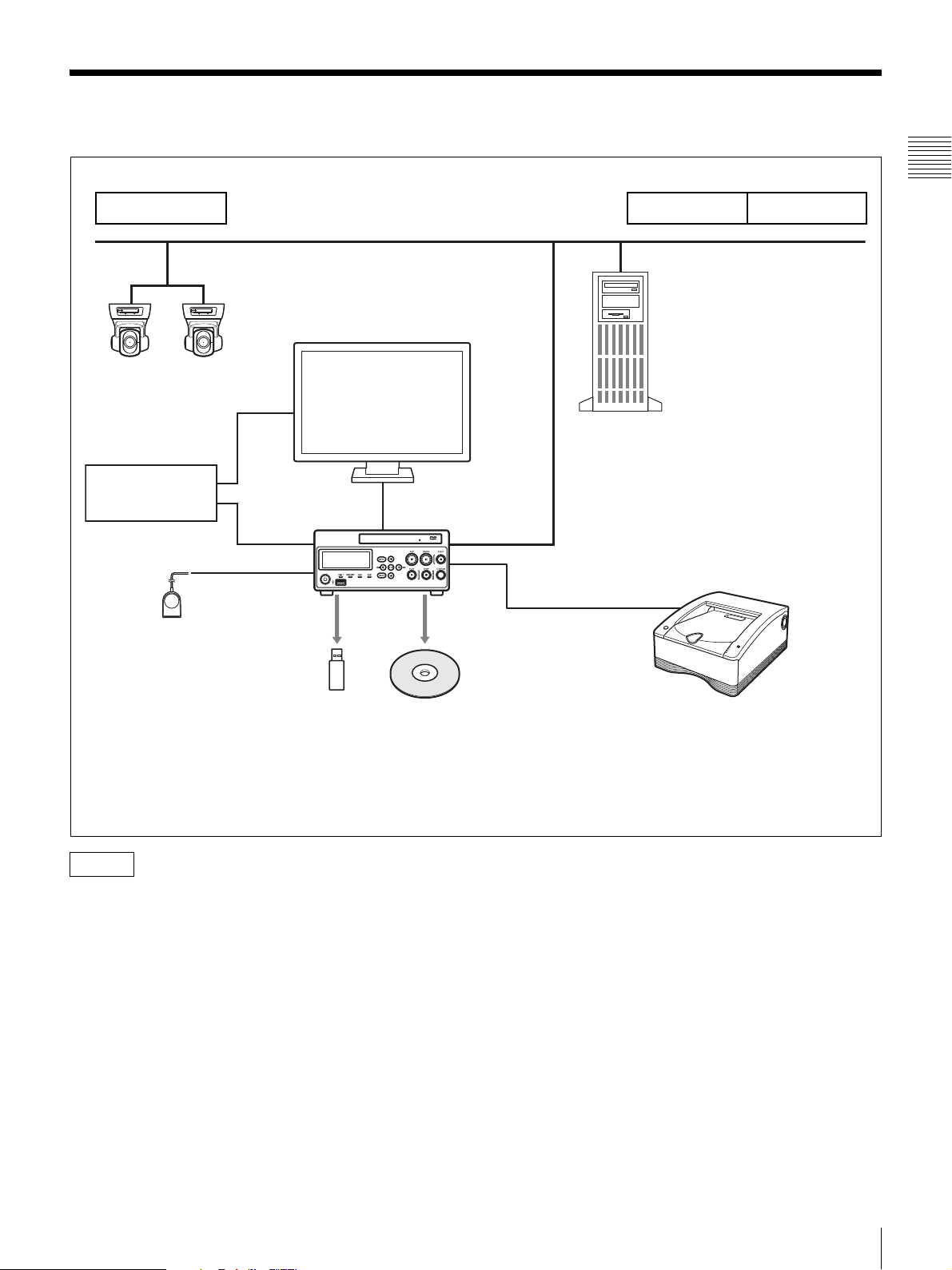
System Configuration Example
Chapter 1 Overview
Operating room
IP cameras in
operating room
Endoscopic device
FS-24
Foot switch
Doctor’s office ICU
Hospital network
File server
HVO-500MD/550MD
Simultaneously record data to one of two
external storage media and the server.
(Recording to DVD is only available on
the HVO-550MD.)
Caution
The FS-24 has an Ingress Protection rating of IPx3.
Therefore, do not operate it environments exposed to
splashing liquids (e.g., surgical operating rooms). For
safety, use a device with a rating of IPx6 or higher when
operating in such environments.
Printer
System Configuration Example
15
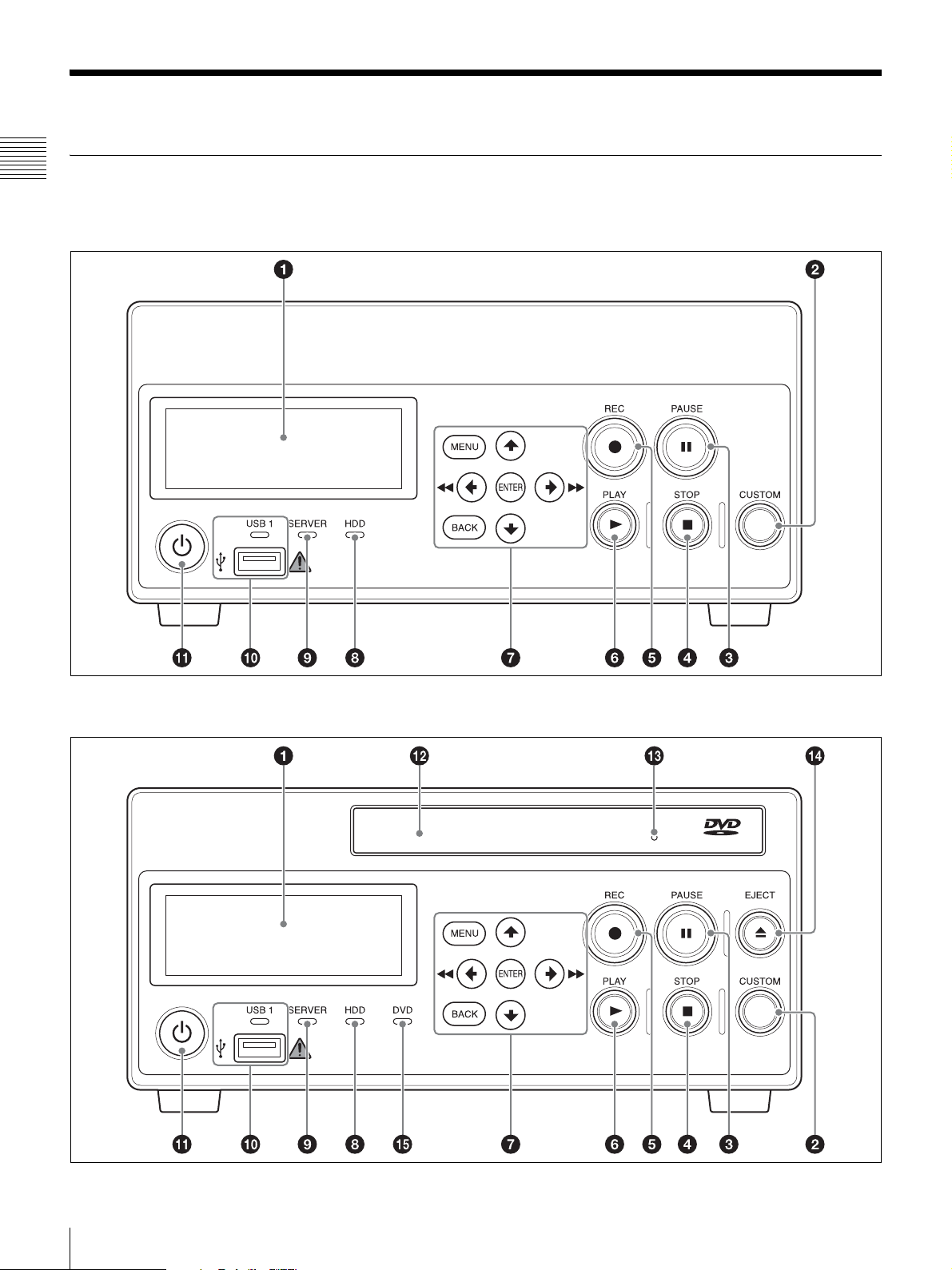
Names and Functions of Parts
Front
Chapter 1 Overview
HVO-500MD
HVO-550MD
16
Names and Functions of Parts

Note
(HVO-550MD only)
Do not touch the laser pickup inside the DVD
drive
The discharge of static electricity that may result from
touching the pickup may cause the drive to hang up,
preventing the ability to write data. If a hang up occurs, try
turning the recorder off and turning it on again.
B / m button
Use this to move the cursor left or select an item that is
to the left of the current item.
You can also use this button to rewind during playback
of recorded data.
v button
Use this to move the cursor down or select an item that
is below the current item.
Chapter 1 Overview
a Front panel display
Displays the current status and messages.
b CUSTOM button
Execute the function assigned to this button.
For details on assigning functions, see “[CUSTOM
Button Control]” under “[General 2] Tab” (page 69).
c X PAUSE button
Use this while recording is in progress to pause
recording. Press this button again to resume recording.
A chapter separator is also created at the position in
which recording was paused.
You can also use this button to pause playback.
To resume playback, press this button again or press
the B PLAY button.
“PAUSE” appears on the front panel display during
pause.
d x STOP button
Use this to stop playback or recording.
A recorded data separator is also created at the position
in which recording was stopped.
e z REC button
Use this to start video/audio recording.
“REC” appears on the front panel display during
recording, in addition to the recording time.
For details on use, see “Manual Recording”
(page 38).
f B PLAY button
• Use this to play back the most recent recorded data
stored on the internal hard disk.
• Press this button while playback is paused to resume
playback.
g Menu navigation buttons
Use these to navigate menus.
MENU button
Display or hide the menu.
V button
Use this to move the cursor up or select an item that is
above the current item.
b / M button
Use this to move the cursor right or select an item that
is to the right of the current item.
You can also use this button to fast forward during
playback of recorded data.
ENTER button
Use this to confirm a currently selected menu or item,
and execute operations. When recording or playback is
not in progress, holding this button for 5 seconds
switches the input signal as follows with each long
press: DVI-D t HDMI t VIDEO t S VIDEO
BACK button
Use this to return to a previous screen during menu or
operation screen displays.
h HDD indicator
Displays the status of the internal hard disk.
Indicator Status
Blinking green The internal hard disk is being
accessed.
Lit green The recording area of the internal hard
disk is full. Delete any unnecessary
recorded data.
Lit orange An error has occurred.
i SERVER indicator
Displays the server access status.
Indicator Status
Blinking green The server is being accessed.
Lit green The recording area of the server is full.
Lit orange An error has occurred.
j USB 1 port/indicator
Connect USB memory devices, external hard disks,
and other USB media here.
The indicators display the status of USB media access.
Indicator Status
Blinking green Data is being written to the USB media.
Lit green The recording area of the USB media
is full. Delete any unnecessary
recorded data, or insert different
media.
Lit orange An error has occurred.
Names and Functions of Parts
17
Note
Never remove the USB media when these indicators
are blinking green.
k 1 (on/standby) switch
Chapter 1 Overview
Use this switch to turn on the unit and the front panel
display.
straightened paper clip into this hole to open the disc
tray.
n Z EJECT button (HVO-550MD only)
Use this to open the disc tray.
o DVD indicator (HVO-550MD only)
Displays the status of the DVD drive.
Tip
To completely shut off the power supply, disconnect
the power cord of the AC adapter.
l Disc tray (HVO-550MD only)
Insert discs here.
m Emergency eject hole (HVO-550MD only)
If the disc tray does not open when you press the Z
EJECT button, insert a long, thin object such as a
Rear
HVO-500MD/550MD
Indicator Status
Blinking green Data is being written to the DVD disc.
Lit green The recording area of the DVD disc is
full. Insert a different disc.
Lit orange An error has occurred.
Note
You cannot remove the disc when this indicator is
blinking green.
18
Names and Functions of Parts
Warning
Warning
Using this unit for medical purposes
This equipment’s connectors are not isolated.
Do not connect any device other than one which conforms
to IEC60601-1.
When an information technology device or AV device that
uses an alternating current is connected, current leakage
may result in an electric shock to the patient or operator.
If use of such a device is unavoidable, isolate its power
supply by connecting an isolation transformer, or by
connecting an isolator between the connecting cables.
After implementing these measures, confirm that the
reduced risk now conforms to IEC60601-1.
Caution
Do not come into contact with the terminals of the rear
panel connectors and patients at the same time.
Doing so may result in a generation of voltage that can be
harmful to patients if the unit is malfunctioning.
Always disconnect the power cord before connecting and
disconnecting connectors.
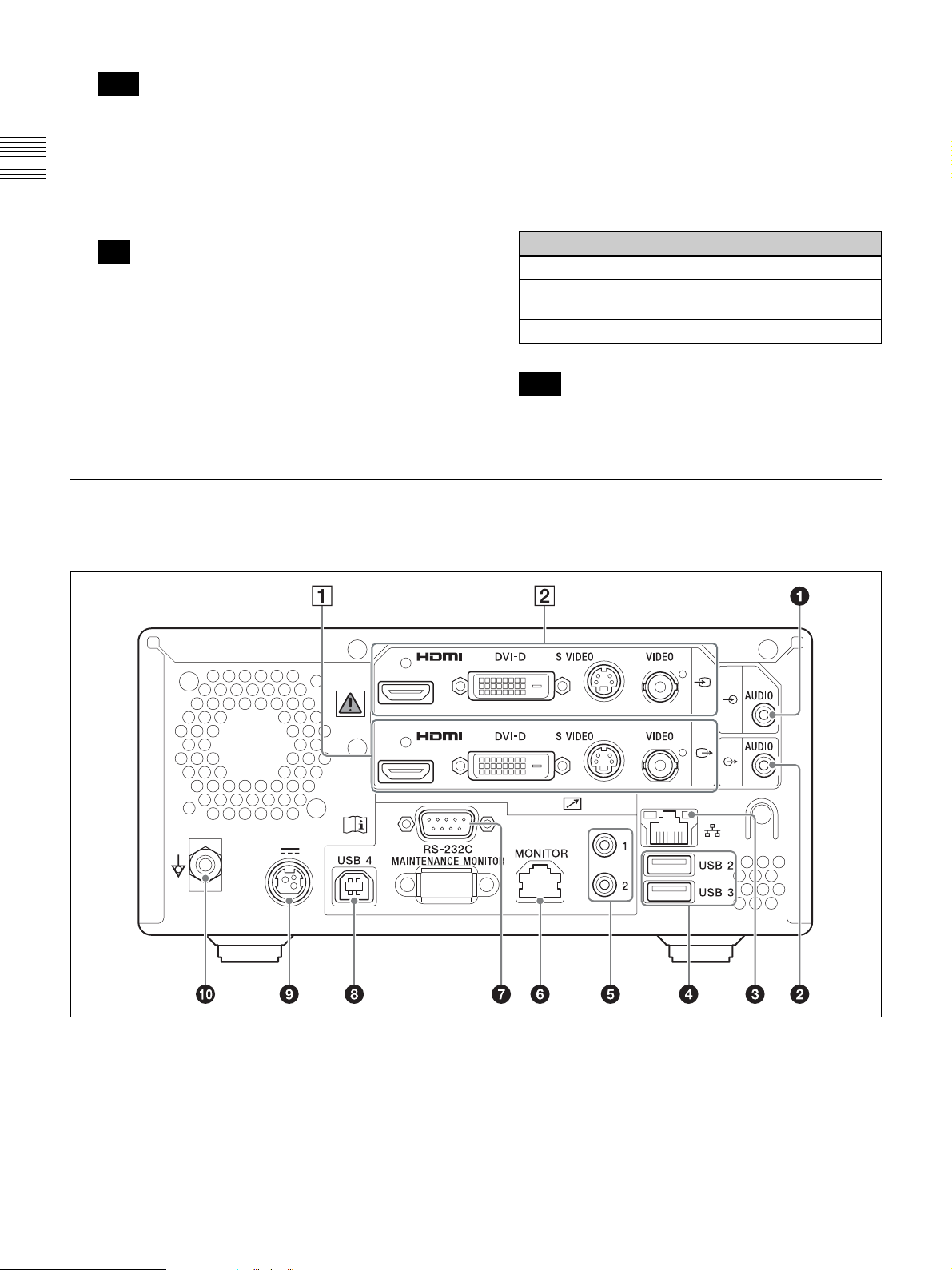
a AUDIO (analog audio signal) input connector
(stereo mini jack)
Inputs analog audio signals.
b AUDIO (analog audio signal) output connector
(stereo mini jack)
Outputs analog audio signals.
Using this unit for medical purposes
The connectors on this unit are not isolated.
Always use USB-compatible external hard drives and
USB memory devices that operate solely on the power
supplied by the unit.
Connecting a device that operates on an AC power
supply may result in an influx of leakage currents from
the connected device, which may in turn result in
electric shocks to the patient and operator.
If use of such devices cannot be avoided, be sure to
connect an isolation transformer to the power supply
of the connected device or connect an isolator between
the connection cables to isolate the power supply, and
verify that the risk of electric shock from the system
has been sufficiently reduced to levels that conform to
IEC60601-1 standards.
e REMOTE contact switch connectors 1 to 2
(stereo mini jack)
Use these to control the unit via contact switches.
For details on contact switches, see “[Contact Switch]
Tab” (page 79).
f REMOTE MONITOR connector (RJ-45)
Use this to perform monitor controls.
For details on monitor controls, see “[Contact
Switch] Tab” (page 79).
Chapter 1 Overview
c Network connector (RJ-45)
Connect a 1000 Base-T or 100 Base-TX network
cable here.
Caution
• For safety, do not connect the connector for
peripheral device wiring that might have excessive
voltage to this port. Follow the instructions for this
port.
• When you connect the LAN cable of the unit to
peripheral device, use a shielded-type cable to
prevent malfunction due to radiation noise.
d USB 2 and 3 ports
Connect USB devices here.
Tip
Supported USB devices
• Use Sony USB media formatted in the FAT32 file
system.
• The connectors do not support all USB devices.
• USB hubs and devices with built-in hubs are not
supported.
g REMOTE RS-232C connector (9-pin D-sub)
Use this connector when controlling this unit or
external devices from a serial interface device.
h USB 4 port
Connect USB devices here. The same controls that can
be performed on an RS-232C device can be performed
on a connected USB device.
i DC IN connector
Connect the DC power cable of the supplied AC
adapter here.
Caution
Connecting the DC connector to the unit before
connecting the AC power cord from the AC adapter.
Conversely, disconnect the AC power cord from the
AC adapter before disconnecting the DC connector.
Do not touch the patient while touching the pins the
DC connector. The 24 V voltage applied to the pins of
the DC connector may adversely the patient.
j Equipotential grounding terminal
Use this for equipotential grounding connections.
Names and Functions of Parts
19
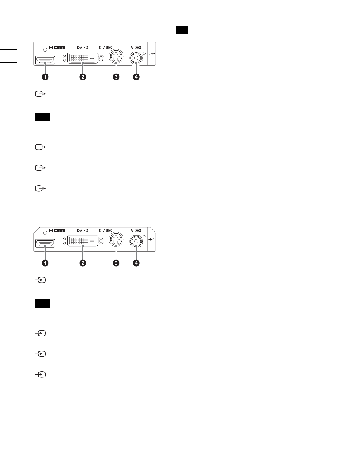
A Video output block
Chapter 1 Overview
a HDMI output connector (Type A)
Outputs HDMI signals.
Note
We recommend using a Sony HDMI cable (not
supplied).
b DVI-D output connector (19-pin DVI)
Outputs DVI-D signals.
c S VIDEO output connector (4-pin mini DIN)
Outputs analog S-Video signals.
d VIDEO output connector (BNC type)
Outputs analog composite video signals.
Tip
If HDMI/DVI-D input images are not displayed, turn on
the unit first and make sure that startup is complete (i.e.,
“READY” appears in the front panel display) before
turning on the video input device.
B Video input block
a HDMI input connector (Type A)
Inputs HDMI signals.
Note
We recommend using a Sony HDMI cable (not
supplied).
b DVI-D input connector (19-pin DVI)
Inputs DVI-D signals.
c S VIDEO input connector (4-pin mini DIN)
Inputs analog S-Video signals.
d VIDEO input connector (BNC type)
Inputs analog composite video signals.
20
Names and Functions of Parts
Preparation
Chapter
2
Chapter 2 Preparation
Connections
1
Connect the DC power cable of the supplied AC
adapter to the DC IN connector on the rear of the unit.
2
Connect the output signal of the medical equipment to
a video input connector on the rear of the unit.
Connect the cable to the appropriate connector based
on the signal type (HDMI, DVI-D, S-Video,
composite video).
Tip
The default setting when you start the unit for the first
time is DVI-D. If you do not have a monitor that
supports DVI-D input, hold the ENTER button for at
least 5 seconds to switch the input signal setting while
confirming selections in the front panel display.
3
Connect the AC power cord of the AC adapter to an
AC power supply.
4
Turn on the medical equipment that will act as the
signal source.
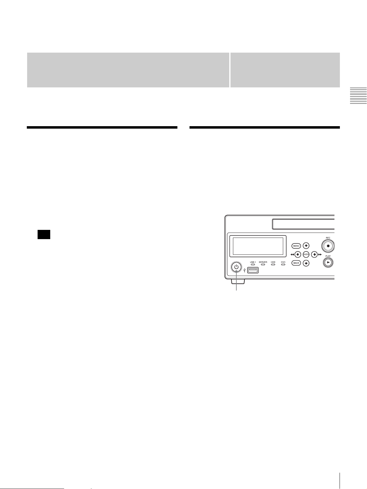
Turning the Unit On and Off
To turn on the unit
Press the 1 (on/standby) switch on the front panel of the
unit.
Front panel
1 (on/standby) switch
When the unit turns on, the front panel display lights and
“WELCOME” appears.
When the front panel display changes from
“BOOTING...” to “READY” you can perform the
following operations.
To turn on power or enter standby during
normal operation
Use the 1 (on/standby) switch to switch between turning
the unit on and entering the standby mode.
When you turn off the unit, “FINISHING” appears on the
front panel display while the unit is shutting down.
“GOODBYE” appears and the display and the unit turn off
when shutdown is complete.
Connections / Turning the Unit On and Off
21

Tip
To completely shut off the power supply, disconnect the
power cord of the AC adapter.
Configuring System Settings
Be sure to configure the system settings before you begin
operating the unit. The system settings should be
configured by the system administrator.
Chapter 2 Preparation
For details on system settings, see “System Administrator
Settings” (page 63).
22
Configuring System Settings
Configuring Recording Settings (User Settings)
Select image inputs and configure image quality settings in
the [User Settings] screen.
You can navigate menus using the navigation buttons on
the front panel of the unit.
Tip
After the unit is turned off, any settings configured in the
[User Settings] screen will revert to the settings configured
under [System Admin Settings].
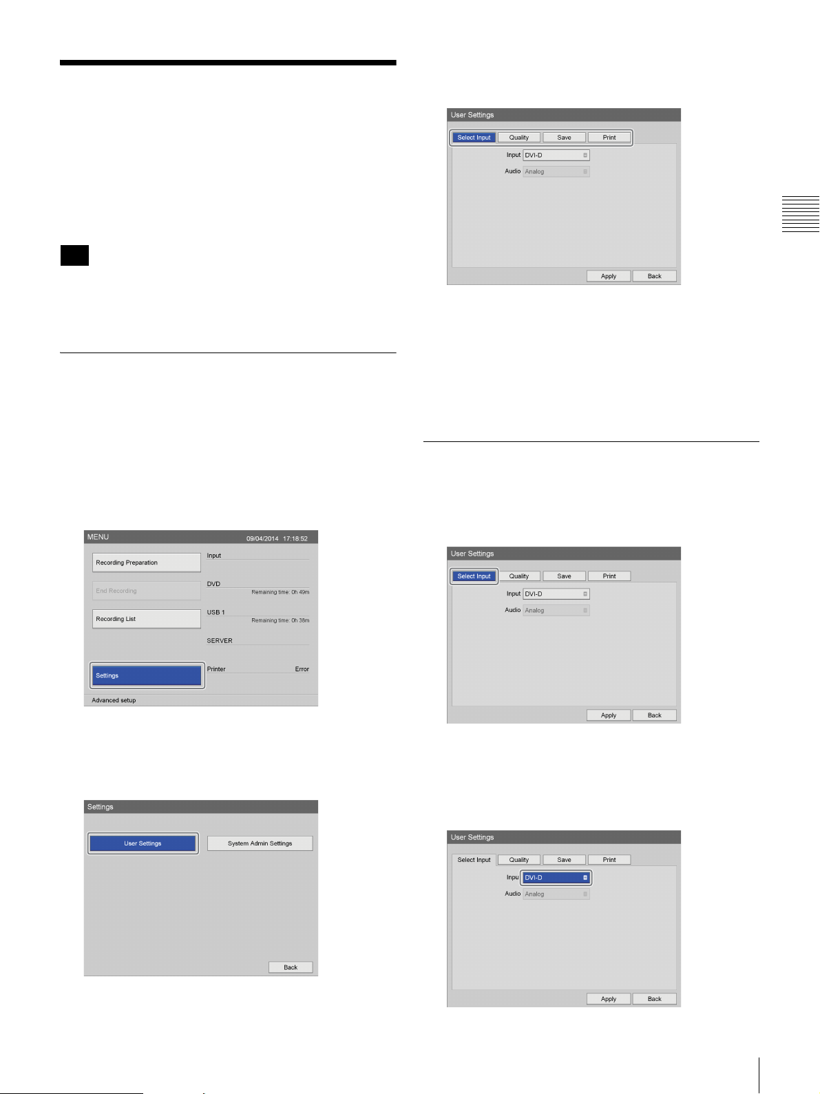
Displaying the [User Settings] Screen
1
Press the MENU button.
4
Use the B and b buttons to select a tab, and press the
ENTER button.
5
Configure the settings in each tab as necessary.
6
When you finish configuration, use the V, v, B, and b
buttons to select [Apply], and press the ENTER
button.
The [Settings] screen appears again.
Chapter 2 Preparation
The [MENU] screen appears.
2
Use the V and v buttons to select [Settings], and press
the ENTER button.
The [Settings] screen appears.
3
Use the B and b buttons to select [User Settings], and
press the ENTER button.
Configuring Input Signal Settings
Select the video and audio input signals.
1
Use the B and b buttons to select the [Select Input] tab.
2
Configure each setting.
Use the
press the ENTER button to display the setting screen
for that item.
V, v, B, and b buttons to select an item, and
The [User Settings] screen appears.
Configuring Recording Settings (User Settings)
23
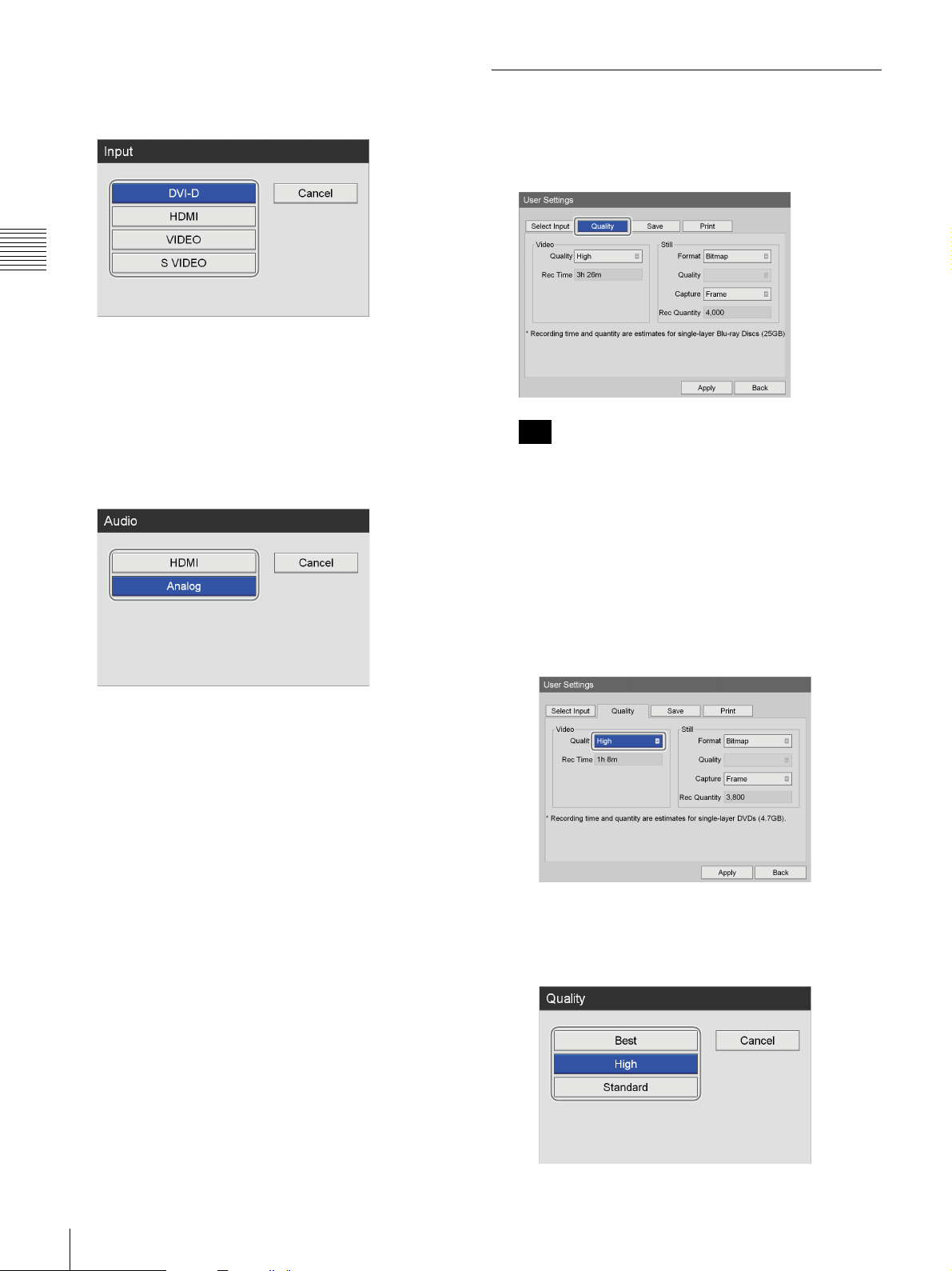
Chapter 2 Preparation
[Input]
Select a video input signal in the setting screen that
appears, and press the ENTER button.
For details on the resolutions that are supported for
each input signal type, contact your local Sony
representative.
[Audio]
When the input signal is set to [HDMI], select the
audio input signal to record in the setting screen that
appears, and press the ENTER button.
The default setting is [HDMI].
Configuring Image Quality Settings
Configure image quality settings for videos.
1
Use the B and b buttons to select the [Quality] tab.
Tip
[Rec Time] and [Rec Quantity] display the following
information.
• For the HVO-500MD: Estimated recording time
available for USB media (500 GB).
• For the HVO-550MD: Estimated recording time
available for single-layer DVD-R1 discs (4.7 GB).
3
To configure image quality settings, proceed to
“Configuring Image Quality Settings” (page 24).
If you are finished configuring, use the
buttons to select [Apply], and press the ENTER
button.
V, v, B, and b
2
Configure the video settings.
1 Use the
press the ENTER button.
The [Quality] screen appears.
2 Use the
and press the ENTER button.
v button to select the [Quality] box, and
V and v buttons to select the image quality,
24
Configuring Recording Settings (User Settings)
The [Quality] screen closes, and the [Quality] tab
appears again.
Tip
The setting configured here will be used as the initial
value for the [Video Quality] setting in the [Recording
Preparation] screen.
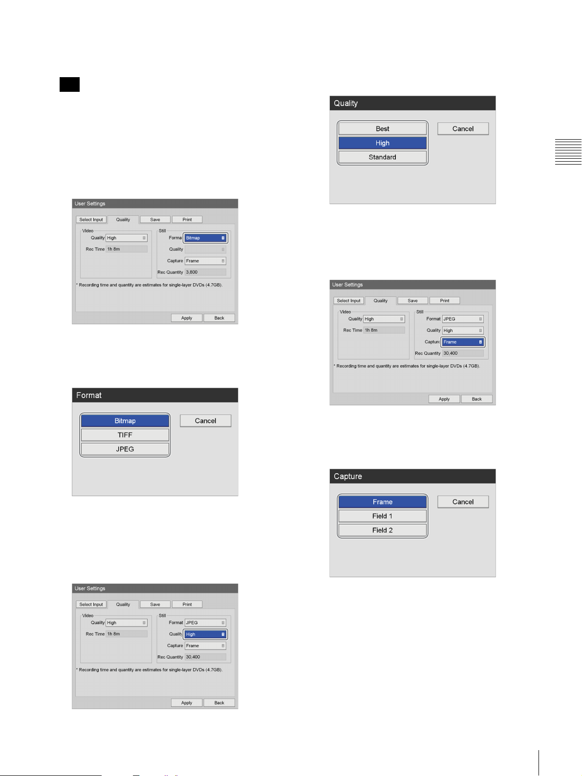
3
Configure the still image settings.
1 Use the
press the ENTER button.
b button to select the [Format] box, and
The [Quality] screen appears.
4 Use the
and press the ENTER button.
The [Quality] screen closes, and the [Quality] tab
appears again.
V and v buttons to select the image quality,
Chapter 2 Preparation
The [Format] screen appears.
2 Use the
still image files, and press the ENTER button.
The [Format] screen closes, and the [Quality] tab
appears again.
V and v buttons to select a format for the
5 Use the
press the ENTER button.
The [Capture] screen appears.
6 Use the
capture mode, and press the ENTER button.
v button to select the [Capture] box, and
V and v buttons to select the frame or field
3 If you selected [JPEG] in step B, use the
to select the [Quality] box, and press the ENTER
button.
v button
The [Capture] screen closes, and the [Quality] tab
appears again.
4
To configure save settings, proceed to “Configuring
Save Settings” (page 26).
If you are finished configuring, use the
buttons to select [Apply], and press the ENTER
button.
Configuring Recording Settings (User Settings)
V, v, B, and b
25

Configuring Save Settings
Configure settings related to external media used to store
recorded data, and specify whether to output metadata.
1
Use the B and b buttons to select the [Save] tab.
Chapter 2 Preparation
2
Configure each setting.
Select an item using the
ENTER button to display the setting screen for that
item.
V and v buttons, and press the
[Metadata Output]
Select whether to include metadata when copying
recorded data to external media in the setting screen
that appears, and press the ENTER button.
The default setting is [Not Used].
Tip
Metadata is saved to the uppermost directory of the
recorded data folder.
[Folder Structure]
Select the directory structure that will be used when
writing to external media in the setting screen that
appears, and press the ENTER button.
The default setting is [Date + Patient ID].
[External Media]
Select the external storage destinations in the setting
screens that appear, and press the ENTER button.
[Record Save to Media]
Select the external storage media to which to copy the
recording list in the setting screen that appears, and
press the ENTER button.
When recorded data with the same patient ID is
created, a new recording date folder is created under
the patient ID folder, and the recorded data is saved to
the new folder.
3
If you set [Metadata Output] to [Use], use the B and b
buttons to select [Advanced], and press the ENTER
button.
The [Advanced] settings screen appears.
26
Configuring Recording Settings (User Settings)
4
Specify the type of metadata to output.
[Recording Date]
Select whether to output the recording date and time as
metadata.
[Patient Info.]
Select whether to output patient information (patient
ID, patient name, gender, date of birth) as metadata.
[Doctor]
Select whether to output the name of the doctor as
metadata.
[Case]
Select whether to output the procedure information as
metadata.
[Facility Name]
Select whether to output the name of the facility as
metadata.
[Metadata Format]
Select [XML] or [TXT].
The default setting is [TXT].
[Encryption]
Displays whether metadata outputs are encrypted
(based on the setting in the [System Admin Settings]).
[Key]
Displays the key as asterisks (*) if [Encryption] is set
to [Use] in the [System Admin Settings].
5
When you finish configuration, use the V, B, b, and v
buttons to select [Apply], and press the ENTER
button.
The [User Settings] screen appears again.
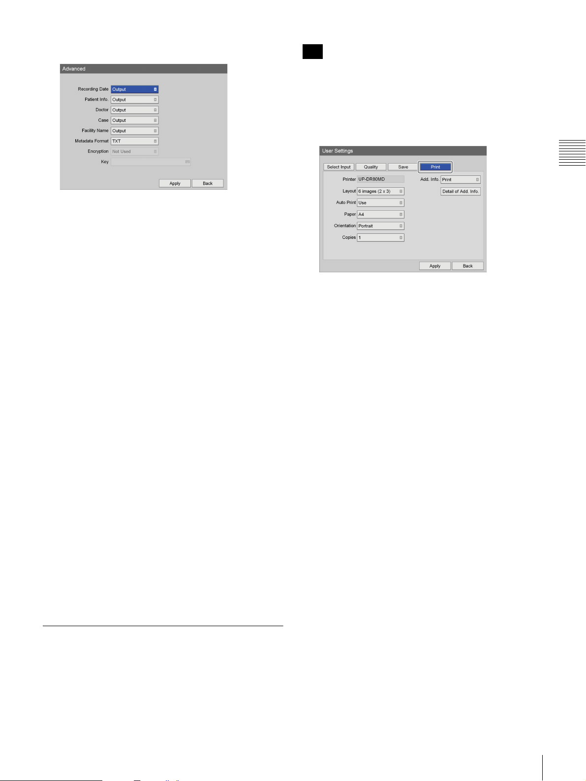
Configuring Print Settings
Configure print settings for still images.
The HVO-500MD/550MD supports connection and use of
the Sony UP-DR80MD printer.
Tip
You can select the printer for use from the [System Admin
Settings] screen – [Device Settings] screen – [Device] tab.
For details on this setting, see “[Device] Tab” (page 76).
1
Use the B and b buttons to select the [Print] tab.
The name of the printer selected for use appears in the
[Printer] box.
2
Configure each setting.
Select an item using the
press the ENTER button to display the setting screen
for that item.
[Layout]
Select the number of still images to print on each sheet.
You can select from 1 image (1 × 1), 2 images (1 × 2),
4 images (2 × 2), 6 images (2 × 3), 8 images (2 × 4),
9 images (3 × 3), 12 images (3 × 4), 15 images (3 × 5),
or 18 images (3 × 6).
The default setting is [6 images (2 × 3)].
[Auto Print]
When you capture a still image while this is set to
[Use] and you are using USB printer, the still image is
automatically printed.
[Paper]
Specify the printer’s paper size.
[Orientation]
Specify the orientation for printing.
The default setting is [Portrait].
[Copies]
Specify the number of copies to print.
The default setting is [1].
[Add. Info.]
Select whether to print the following additional
information (recording date, patient information, etc.).
You can also individually select whether to print each
additional information item in the [Detail of Add.
Info.] screen.
V, B, b, and v buttons, and
Chapter 2 Preparation
Configuring Recording Settings (User Settings)
27

Chapter 2 Preparation
The default setting is [Not Printed] for all settings
except [Rec Timestamp].
Tip
To print watermarks or logos, you must import the
watermarks files and logo files onto the unit
beforehand.
The items that can be configured in the [Detail of Add.
Info.] screen are as follows.
[Logo]
Select whether to print logos.
[Recording Date]
Select whether to print the date on which the image
was recorded.
[Patient Info.]
Select whether to print patient information.
[Doctor]
Select whether to print the name of the doctor.
[Case]
Select whether to print the name of the procedure.
[Facility Name]
Select whether to print the name of the facility.
[Rec Timestamp]
Select whether to print the time at which the image was
recorded.
[Watermark]
Select whether to print watermarks.
Tips
• To print watermarks, you must import a watermark
file that is created in the proper format beforehand.
You can import the watermark file from the [System
Admin Settings] screen - [Device Settings] screen [Device] tab.
• To print logos, you must import a logo file that is
created in the proper format beforehand. You can
import the logo file from the [System Admin
Settings] screen - [Device Settings] screen [Device] tab.
For details on importing, see “[Import Watermark]”
(page 78) and “[Import Logo]” (page 78).
3
When you finish configuration, use the V, v, B, and b
buttons to select [Apply], and press the ENTER
button.
The [User Settings] screen appears again.
28
Configuring Recording Settings (User Settings)
Using the On-Screen Keyboard (Text Entry)
1
q
0987
23
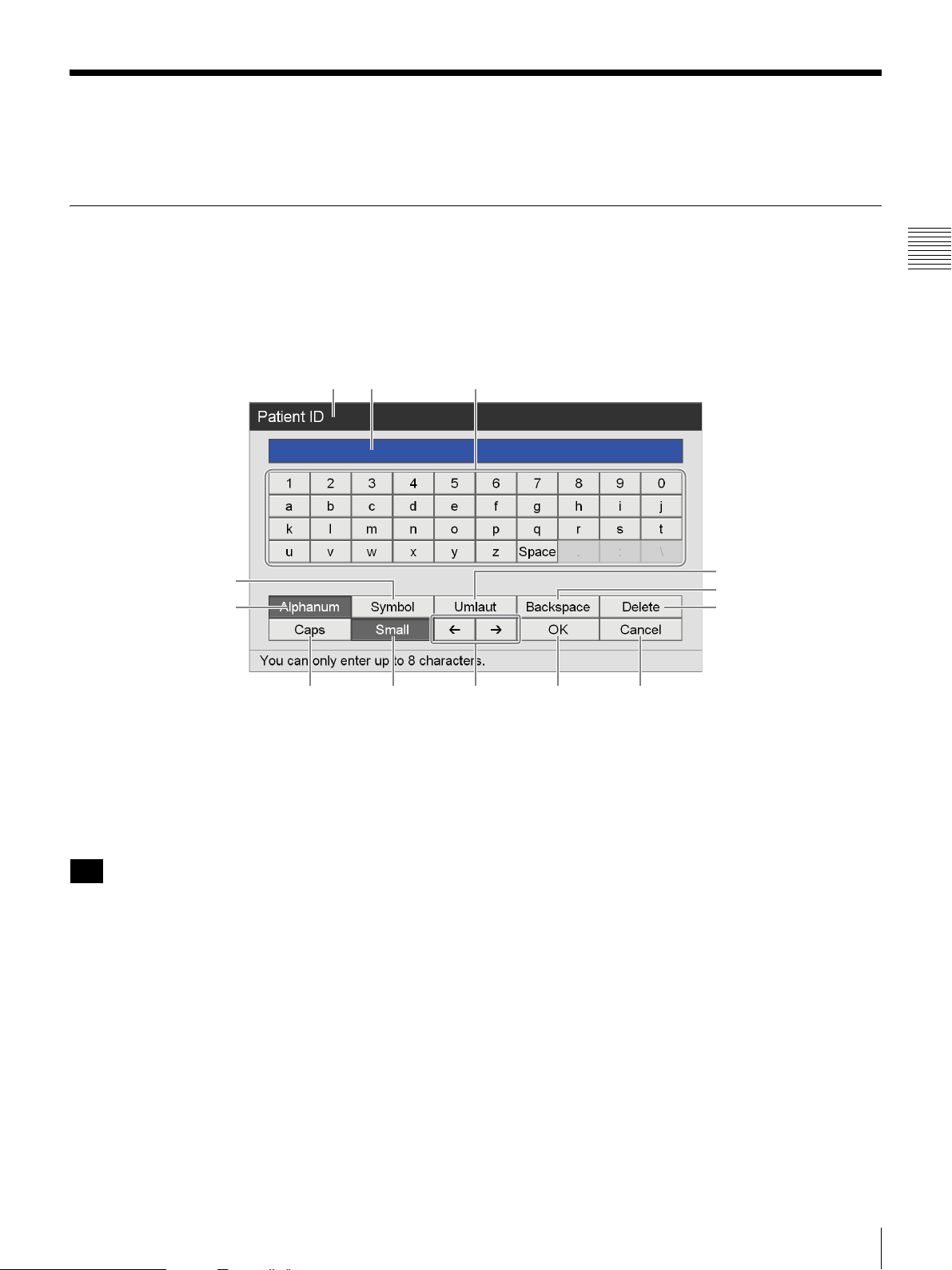
When text entry is necessary, an on-screen keyboard appears.
Names and Functions of Parts (On-Screen Keyboard)
You can display an alphanumeric, symbol, or umlaut character set on the onscreen keyboard.
The name and function of each part on the keyboard is as follows.
Example: On-screen keyboard during alphanumeric character display
qd
qs
a
Chapter 2 Preparation
4
5
6
A Title bar
The name of the setting item for which the on-screen
keyboard was opened is displayed here.
B Entry box
Characters selected on the keyboard are entered here.
Tip
Characters input on a hardware keyboard are also entered
here.
C Keyboard
When you select a character you want to input using the
V,
v, B, and b buttons and then press the ENTER button, the
character is entered in the B entry box.
D [Umlaut]
Select this and press the ENTER button to switch the
keyboard to umlaut character display.
E [Backspace]
Select this and press the ENTER button to discard the
character immediately preceding the cursor.
F [Delete]
Select this and press the ENTER button to discard the
character immediately following the cursor.
G [Cancel]
Select this and press the ENTER button to cancel text entry
and close the on-screen keyboard.
H [OK]
When you select this and press the ENTER button, the text
that appears in the entry box is applied and input in the
settings screen.
I
B / b
Select this and press the ENTER button to move the cursor
one space to the left or right.
J [Small]
Select this and press the ENTER button to switch the
keyboard to lower case display.
Using the On-Screen Keyboard (Text Entry)
29
K [Caps]
Select this and press the ENTER button to switch the
keyboard to upper case display.
Handling Discs
L [Alphanum]
Select this and press the ENTER button to switch the
keyboard to alphanumeric character display.
M [Symbol]
Select this and press the ENTER button to switch the
keyboard to symbol display.
Chapter 2 Preparation
Compatible discs
This unit supports the following DVD disc.
• DVD-R (single layer)
Tip
This unit supports data discs only. Video discs are not
compatible.
Note
If you play back a DVD disc that was recorded using this
unit on a computer running Windows XP, additional
recording to that disc may become disabled.
Disc formatting
This unit automatically formats new and previously
unused discs.
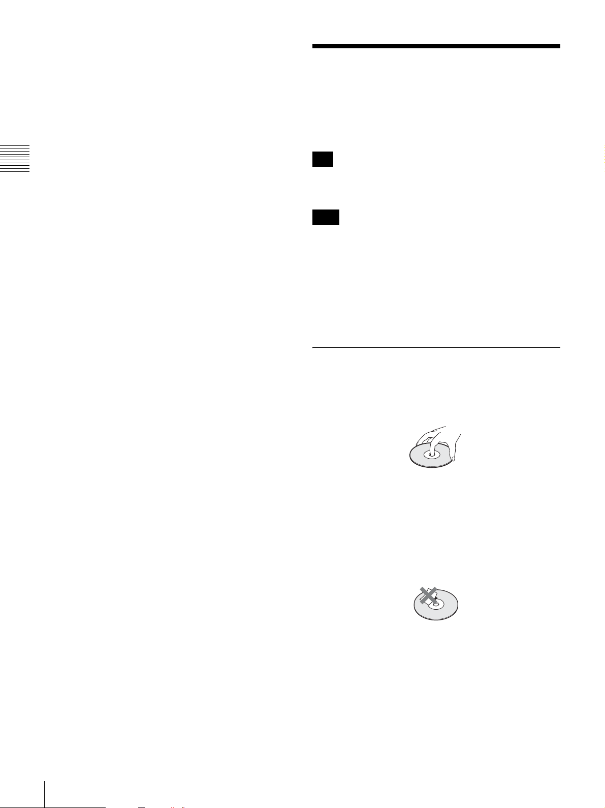
Notes on Handling
Handling
• Do not touch the recording or playback surface of the
disc. Handle the disc by its edge.
• Do not use the following types of disc. Doing so may
cause the unit to malfunction.
– A disc on which a paper label or a seal is attached
– A disc on which the glue of cellophane tape or a label,
or on which a portion of a label still remains
– A cracked disc
– A cracked disc which has been mended using glue (or
a similar substance)
Storage
• Do not store discs where they may be subjected to direct
sunlight, or in other places where the temperature or
humidity is high.
• Store discs in their cases.
• Finger prints or dust accumulated on the disc cause
deterioration of picture quality. Keep the disc clean.
30
Handling Discs
 Loading...