

Sony HVO-3300MT Instructions For Use Manual

4-596-607-13 (1)
2018-08
3D HD Video Recorder
Instructions for Use
Before operating the unit, please read this manual thoroughly
and retain it for future reference.
HVO-3300MT
© 2016 Sony Corporation
Indications for Use/Intended Use
Sony Medical Recorders are intended to record video and
still images from ultrasound, digital X-ray, endoscopic,
laparoscopic and other compatible diagnostic imaging
systems and surgical imaging systems. These medical
grade recorders can save recorded images to an internal
hard disk drive, a portable USB drive, an optical disk or
to a compatible network server. The recorded images can
be used for the patient record, training or education or for
sending to referring physicians. The recorders are suitable
for use in hospital radiology and operating rooms,
diagnostic imaging centers, surgical centers, clinics,
doctors’ offices and similar medical environments.
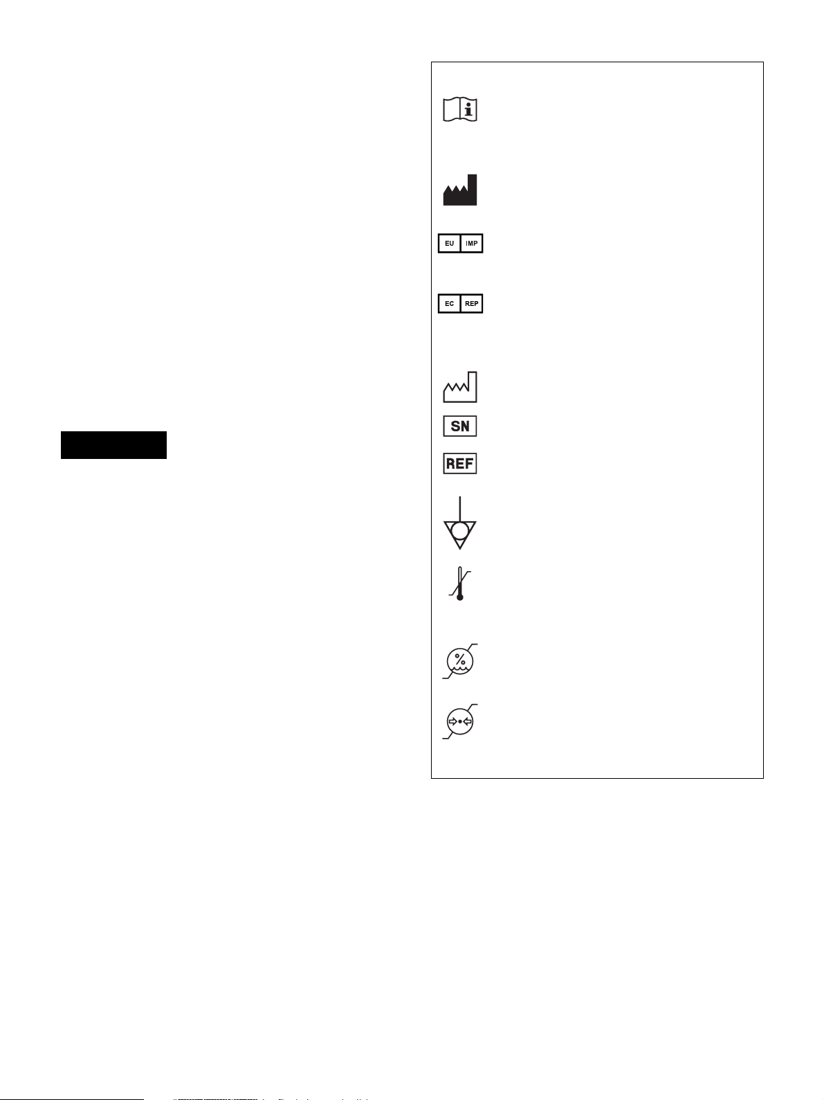
Symbols on the product
Consult the instructions for use
Follow the directions in the instructions for
use for parts of the unit on which this symbol
appears.
This symbol indicates the manufacturer, and
appears next to the manufacturer’s name and
address.
This symbol indicates the EU Importer, and
appears next to the EU Importer’s name and
address.
Notes
• Images recorded with this equipment cannot be used for
diagnostic use.
• This equipment is for medical professionals.
• This equipment is intended for use in medical
environments, such as clinics, laboratory rooms, and
operating rooms.
Warning
To reduce the risk of fire or electric shock, do not
expose this equipment to rain or moisture.
To avoid electrical shock, do not open the
cabinet. Refer servicing to qualified personnel
only.
No modification of this equipment is allowed.
Warning
To avoid the risk of electric shock, this
equipment must only be connected to a supply
mains with protective earth.
Warning
To disconnect the main power, unplug the power plug.
When installing the unit, incorporate a readily accessible
disconnect device in the fixed wiring, or connect the
power plug to an easily accessible socket-outlet near the
unit.
Do not position the ME equipment where it is difficult to
unplug the power plug.
If a fault should occur during operation of the unit,
operate the disconnect device to switch the power supply
off, or disconnect the power plug.
This symbol indicates the European
Community representative, and appears next
to the European Community representative’s
name and address.
This symbol indicates the date of
manufacture.
This symbol indicates the serial number.
This symbol indicates the version of the
accompanying document.
This symbol indicates the equipotential
terminal which brings the various parts of a
system to the same potential.
Storage and transport temperature
This symbol indicates the acceptable
temperature range for storage and transport
environments.
Storage and transport humidity
This symbol indicates the acceptable humidity
range for storage and transport environments.
Storage and transport pressure
This symbol indicates the acceptable
atmospheric pressure range for storage and
transport environments.
For customers in the U.S.A.
This equipment has been tested and found to comply with
the limits for a Class A digital device, pursuant to part 15
of the FCC Rules. These limits are designed to provide
reasonable protection against harmful interference when
the equipment is operated in a commercial environment.
This equipment generates, uses and can radiate radio
frequency energy and, if not installed and used in
accordance with the instruction manual, may cause
harmful interference to radio communications. Operation
of this equipment in a residential area is likely to cause
harmful interference in which case the user will be
required to correct the interference at his own expense.
2
You are cautioned that any changes or modifications not
expressly approved in this manual could void your
authority to operate this equipment.
All interface cables used to connect peripherals must be
shielded in order to comply with the limits for a digital
device pursuant to Subpart B of part 15 of FCC Rules.
For customers in the U.S.A.
Caution
Federal law (United States of America) restricts this
device to sale by or on the order of a licensed healthcare
practitioner.
For customers in Canada
CAN ICES-3 (A)/NMB-3(A)
For customers in Canada
This unit has been certified according to Standard CAN/
CSA-C22.2 No. 60601-1.
– Relocate the unit with respect to the affected
devices.
– Connect the unit and the affected devices to
different branch circuits.
For more information, consult qualified Sony service
personnel.
(Applicable standard: IEC 60601-1-2)
Important safeguards and notices for use
in the medical environments
1. All devices connected to the unit must be certified or
compliant according to IEC 60601-1, IEC 60950-1,
and IEC 60065 standards and other IEC/ISO
standards applicable to the devices.
2. Furthermore, the system as a whole must comply with
IEC 60601-1 standards. All peripheral devices
connected to the signal input/output sections of the
unit constitute the medical-use system, and therefore,
the user is responsible for ensuring that the system as
a whole complies with IEC 60601-1 standards. If in
doubt, consult qualified Sony service personnel.
3. Connecting the unit to other devices may increase the
leakage current.
4. For all peripheral devices connected to the unit that
operate on commercial power supplies and do not
comply with IEC 60601-1 standards, incorporate an
isolation transformer that complies with IEC 60601-1
standards and connect to the commercial power
supply via the transformer.
5. The unit generates, uses, and may radiate radio
frequency energy. If it is not installed and used in
accordance with the instruction manual, it may cause
interference on other devices. If the unit causes
interference (which can be determined by
disconnecting the power cord from the unit), try the
following.
3

Important EMC notices for use in medical environments
• The HVO-3300MT needs special precautions regarding EMC and needs to be installed and put into service according
to the EMC information provided in the instructions for use.
• The HVO-3300MT is intended for use in a professional healthcare facility environment.
• Portable and mobile RF communications equipment, such as cellular phones, can affect the HVO-3300MT.
Warning
• Portable RF communications equipment should be used no closer than 30 cm (12 inches) to any part of the
HVO-3300MT. Otherwise, degradation of the performance of this equipment could result.
• If the HVO-3300MT will be used adjacent to or stacked with other equipment, normal operation of the HVO-3300MT
under such configurations should be verified via observation.
• The use of accessories and cables other than those specified, with the exception of replacement parts sold by Sony
Corporation, may result in increased emissions or decreased immunity of the HVO-3300MT.
Guidance and manufacturer’s declaration – electromagnetic emissions
The HVO-3300MT is intended for use in the electromagnetic environment specified below. The customer or the user of
the HVO-3300MT should assure that it is used in such an environment.
Emission test Compliance Electromagnetic environment – guidance
RF emissions
CISPR 11
RF emissions
CISPR 11
Harmonic emissions
IEC 61000-3-2
Voltage fluctuations/
flicker emissions
Group 1
Class B
Class A
Complies
The HVO-3300MT uses RF energy only for its internal
function. Therefore, its RF emissions are very low and are
not likely to cause any interference in nearby electronic
equipment.
The HVO-3300MT is suitable for use in all establishments,
including domestic establishments and those directly
connected to the public low-voltage power supply network
that supplies buildings used for domestic purposes.
IEC 61000-3-3
4

Guidance and manufacturer’s declaration – electromagnetic immunity
The HVO-3300MT is intended for use in the electromagnetic environment specified below. The customer or the user of
the HVO-3300MT should assure that it is used in such an environment.
Immunity test
Electrostatic
discharge (ESD)
IEC 60601
test level
Compliance level Electromagnetic environment – guidance
±8 kV contact ±8 kV contact Floors should be wood, concrete or ceramic tile. If
floors are covered with synthetic material, a relative
humidity of at least 30% is recommended.
IEC 61000-4-2 ±15 kV air ±15 kV air
Electrical fast
transient/burst
±2 kV for power
supply lines
±2 kV for power
supply lines
Mains power quality should be that of a typical
commercial or hospital environment.
IEC 61000-4-4 ±1 kV for input/
output lines
Surge ±1 kV line(s) to
line(s)
IEC 61000-4-5 ±2 kV line(s) to
earth
Voltage dips, short
interruptions and
voltage variations
on power supply
input lines
IEC 61000-4-11
0% U
T
(100% dip in UT)
for 0.5/1 cycles
40% U
T
(60% dip in UT)
for 5 cycles
70% U
T
(30% dip in UT)
for 25/30 cycles
(for 0.5 sec)
0% U
T
(100% dip in UT)
for 250/300 cycles
(for 5 sec)
Power frequency
30 A/m 30 A/m Power frequency magnetic fields should be at levels
(50/60 Hz)
magnetic field
±1 kV for input/
output lines
±1 kV differential
mode
±2 kV common
mode
0% U
(100% dip in UT)
a
for 0.5/1 cycles
40% U
(60% dip in UT)
for 5 cycles
70% U
(30% dip in UT)
a
for 25/30 cycles
(for 0.5 sec)
0% U
(100% dip in UT)
a
for 250/300 cycles
(for 5 sec)
Mains power quality should be that of a typical
commercial or hospital environment.
T
Mains power quality should be that of a typical
commercial or hospital environment. If the user of the
HVO-3300MT requires continued operation during
a
power mains interruptions, it is recommended that the
T
T
T
HVO-3300MT be powered from an uninterruptible
power supply or a battery.
a
a
characteristic of a typical location in a typical
commercial or hospital environment.
IEC 61000-4-8
NOTE: U
is the a.c. mains voltage prior to application of the test level.
T
a For example, 10/12 means 10 cycles at 50 Hz or 12 cycles at 60 Hz.
5
Guidance and manufacturer’s declaration – electromagnetic immunity
The HVO-3300MT is intended for use in the electromagnetic environment specified below. The customer or the user of
the HVO-3300MT should assure that it is used in such an environment.
Immunity test
IEC 60601
test level
Compliance level Electromagnetic environment – guidance
Portable and mobile RF communications equipment
should be used no closer to any part of the
HVO-3300MT, including cables, than the recommended
separation distance calculated from the equation
appliance to the frequency of the transmitter.
Recommended separation distance
Conducted RF
3 Vrms
3 Vrms d = 1.2 √P
150 kHz to 80 MHz
IEC 61000-4-6
outside ISM bands
6 Vrms
c
6 Vrms
150 kHz to 80 MHz
in ISM bands
c
Radiated RF 3 V/m 3 V/m IEC 60601-1-2: 2007
IEC 61000-4-3 80 MHz to 2.7 GHz
d = 1.2 √P 80 MHz to 800 MHz
d = 2.3 √P 800 MHz to 2.5 GHz
IEC 60601-1-2: 2014
d = 2.0 √P 80 MHz to 2.7 GHz
Where P is the maximum output power rating of the
transmitter in watts (W) according to the transmitter
manufacturer and d is the recommended separation
distance in meters (m).
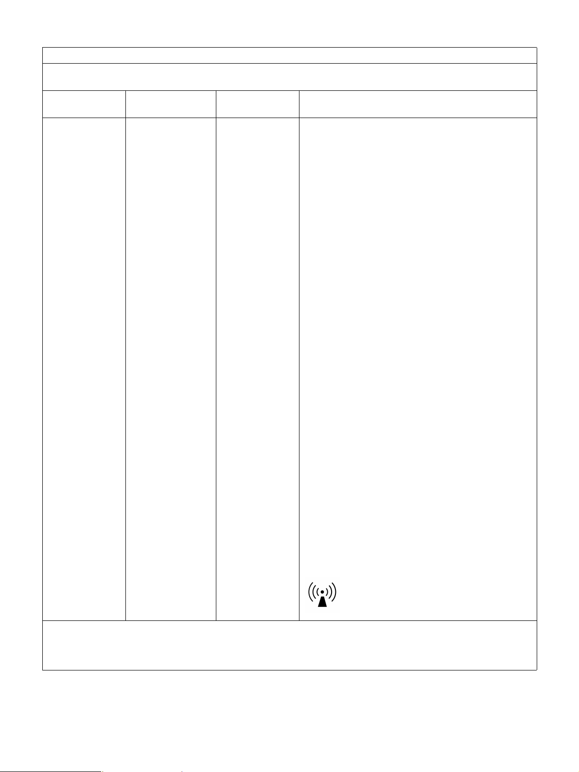
Field strengths from fixed RF transmitters, as
determined by an electromagnetic site survey,
be less than the compliance level in each frequency
b
range.
a
should
Interference may occur in the vicinity of equipment
marked with following symbol:
NOTE 1: At 80 MHz and 800 MHz, the higher frequency range applies.
NOTE 2: These guidelines may not apply in all situations. Electromagnetic propagation is affected by absorption and
reflection from structures, objects and people.
6
a Field strengths from fixed transmitters, such as base stations for radio (cellular/cordless) telephones and land mobile
radios, amateur radio, AM and FM radio broadcast and TV broadcast cannot be predicted theoretically with accuracy.
To assess the electromagnetic environment due to fixed RF transmitters, an electromagnetic site survey should be
considered. If the measured field strength in the location in which the HVO-3300MT is used exceeds the applicable
RF compliance level above, the HVO-3300MT should be observed to verify normal operation. If abnormal
performance is observed, additional measures may be necessary, such as reorienting or relocating the HVO-3300MT.
b Over the frequency range 150 kHz to 80 MHz, field strengths should be less than 3 V/m.
c The ISM (industrial, scientific and medical) bands between 150 kHz and 80 MHz are 6.765 MHz to 6.795 MHz;
13.553 MHz to 13.567 MHz; 26.957 MHz to 27.283 MHz; and 40.66 MHz to 40.70 MHz.
Recommended separation distances between portable and mobile RF communications equipment
and the HVO-3300MT
The HVO-3300MT is intended for use in an electromagnetic environment in which radiated RF disturbances are
controlled. The customer or the user of the HVO-3300MT can help prevent electromagnetic interference by maintaining
a minimum distance between portable and mobile RF communications equipment (transmitters) and the HVO-3300MT
as recommended below, according to the maximum output power of the communications equipment.
Separation distance according to frequency of transmitter
m
Rated maximum output
power of transmitter
W
150 kHz to
80 MHz
d = 1.2 √P
IEC 60601-1-2 : 2007 IEC 60601-1-2 : 2014
80 MHz to
800 MHz
d = 1.2 √P
800 MHz to
2.5 GHz
d = 2.3 √P
150 kHz to
80 MHz
d = 1.2 √P
80 MHz to
2.7 GHz
d = 2.0 √P
0.01 0.12 0.12 0.23 0.12 0.20
0.1 0.38 0.38 0.73 0.38 0.63
1 1.2 1.2 2.3 1.2 2.0
10 3.8 3.8 7.3 3.8 6.3
100 12 12 23 12 20
For transmitters rated a maximum output power not listed above, the recommended separation distance d in meters (m)
can be estimated using the equation applicable to the frequency of the transmitter, where P is the maximum output
power rating of the transmitter in watts (W) according to the transmitter manufacturer.
NOTE 1: At 80 MHz and 800 MHz, the separation distance for the higher frequency range applies.
NOTE 2: These guidelines may not apply in all situations. Electromagnetic propagation is affected by absorption and
reflection from structures, objects and people.
7

Guidance and manufacturer’s declaration – electromagnetic immunity
The HVO-3300MT is intended for use in an electromagnetic environment in which radiated RF disturbances are
controlled. Portable RF communications equipment should be used no closer than 30 cm (12 inches) to any part of the
HVO-3300MT. Otherwise, degradation of the performance of this equipment could result.
Immunity test Band
380 – 390 MHz TETRA 400
430 – 470 MHz
704 – 787 MHz LTE Band 13, 17
a
Service
a
Modulation
Pulse modulation
18 Hz
GMRS 460
FRS 460
FM
±5 kHz deviation
1 kHz sine
Pulse modulation
217 Hz
IEC 60601
test level
Compliance level
27 V/m 27 V/m
28 V/m 28 V/m
9 V/m 9 V/m
GSM 800/900
Proximity fields
from RF wireless
communications
equipment
IEC 61000-4-3
800 – 960 MHz
1,700 – 1,990 MHz
TETRA 800
iDEN 820
CDMA 850
LTE Band 5
GSM 1800
CDMA 1900
GSM 1900
DECT
LTE Band 1, 3, 4,
Pulse modulation
18 Hz
Pulse modulation
217 Hz
28 V/m 28 V/m
28 V/m 28 V/m
25
UMTS
Bluetooth
2,400 – 2,570 MHz
WLAN
802. 11 b/g/n
RFID 2450
Pulse modulation
217 Hz
28 V/m 28 V/m
LTE Band 7
5,100 – 5,800 MHz WLAN 802. 11 a/n
Pulse modulation
217 Hz
9 V/m 9 V/m
NOTE: These guidelines may not apply in all situations. Electromagnetic propagation is affected by absorption and
reflection from structures, objects and people.
a For some services, only the uplink frequencies are included.
8
Caution
When you dispose of the unit or accessories, you must
obey the laws in the relative area or country and the
regulations in the relative hospital regarding
environmental pollution.
Warning on power connections
Use a proper power cord for your local power supply.
1. Use the approved Power Cord (3-core mains lead) /
Appliance Connector / Plug with earthing-contacts
that conforms to the safety regulations of each country
if applicable.
2. Use the Power Cord (3-core mains lead) / Appliance
Connector / Plug conforming to the proper ratings
(Voltage, Ampere).
If you have questions on the use of the above Power Cord /
Appliance Connector / Plug, please consult a qualified
service personnel.
Warning
When not using the remote for an extended period of
time, remove the batteries to avoid possible damage from
battery leakage and corrosion.
Warning
Batteries shall not be exposed to excessive heat such as
sunshine, fire or the like.
This model (HVO-3300MT) is classified as a CLASS 1
LASER PRODUCT. (IEC 60825-1: 2007 and IEC 608251: 2014)
Caution
Use of controls or adjustments or performance of
procedures other than those specified herein may result in
hazardous radiation exposure.
Warning on power connections for
medical use
Customers in the U.S.A. and Canada should use the
following type of power cord.
Customers in other countries or regions should use the
power cord prescribed by their country or region.
U.S.A. and Canada
Plug type HOSPITAL GRADE
Cord type Min. Type SJT
Min. 18 AWG
Minimum rating for plug
and appliance couplers
Safety approval UL Listed and CSA
* Note: Grounding reliability can only be achieved when
the equipment is connected to an equivalent receptacle
marked “Hospital Only” or “Hospital Grade”.
10 A / 125 V
*
Caution
Danger of explosion if battery is incorrectly replaced.
Replace only with the same or equivalent type
recommended by the manufacturer.
When you dispose of the battery, you must obey the law
in the relative area or country.
Caution
The use of optical instruments with this product will
increase eye hazard.
Warning
The apparatus shall not be exposed to dripping or
splashing. No objects filled with liquids, such as vases,
shall be placed on the apparatus.
Caution
When installing, ensure the following space around the
periphery of the unit, taking ventilation and servicing into
consideration.
– Rear side: 10 cm (4 in.) or more
– Left/Right sides: 10 cm (4 in.) or more
– Top side: 10 cm (4 in.) or more
Caution
Do not come into contact with the unit’s internal circuits
and patients at the same time.
Doing so may result in a generation of voltage that can be
harmful to patients if the unit is malfunctioning.
9
Caution
Do not use the device in a MR (Magnetic Resonance)
environment.
It may cause a malfunction, fire, and unwanted
movement.
Warning
Excessive sound pressure from earphones and
headphones can cause hearing loss.
In order to use this product safely, avoid prolonged
listening at excessive sound pressure levels.
For the State of California, USA only
Perchlorate Material - special handling may apply, See
www.dtsc.ca.gov/hazardouswaste/perchlorate
For the customers in the U.S.A.
SONY LIMITED WARRANTY
http://www.sony.com/psa/warranty
information and complete terms and conditions of
Sony’s limited warranty applicable to this product.
- Please visit
for important
For the customers in Canada
SONY LIMITED WARRANTY
http://www.sonybiz.ca/pro/lang/en/ca/article/resourceswarranty for important information and complete terms
and conditions of Sony’s limited warranty applicable to
this product.
For the customers in Europe
Sony Professional Solutions Europe - Standard
Warranty and Exceptions on Standard Warranty.
Please visit http://www.pro.sony.eu/warranty
important information and complete terms and
conditions.
For the customers in Korea
SONY LIMITED WARRANTY
http://bpeng.sony.co.kr/handler/BPAS-Start
important information and complete terms and
conditions of Sony’s limited warranty applicable to this
product.
- Please visit
for
- Please visit
for
10

Table of Contents
Please Read First ....................................14
Usage Notes.............................................16
Factory Assigned Functions........................ 40
Other Assignable Functions ........................ 41
Chapter 3 Basic Recorder
Operations
Chapter 1 Overview
Features ...................................................17
System Configuration Example .............19
Names and Functions of Parts...............20
Front ............................................................ 20
Rear.............................................................. 23
Infrared Remote Control Unit
(RM-M010) .................................................25
Status Displays ............................................26
External Device Status Displays ................. 28
Setting Screens ............................................28
Using the On-Screen Keyboard
(Text Entry) ..............................................29
Names and Functions of Parts (On-Screen
Keyboard) .................................................... 29
Handling Discs ........................................30
Notes on Handling....................................... 30
Inserting and Removing Discs..................... 31
Chapter 2 Preparation
Connections.............................................32
Turning the Unit On and Off...................32
Configuring System Settings.................33
Configuring Recording Settings
(User Settings).........................................34
Displaying the [User Settings] Screen......... 34
Configuring Input/Output Signal Settings... 34
Configuring Image Quality Settings............ 35
Configuring Recording and
Streaming Settings....................................... 35
Configuring Save Settings........................... 36
Configuring Print Settings........................... 38
Configuring Other Settings.......................... 39
Configuring PinP Settings ........................... 39
Function Keys..........................................40
Using Function Keys ................................... 40
Operation Flow........................................ 42
Step 1: Record......................................... 42
Step 2: Capture Still Images ..................43
Step 3: Quick Playback .......................... 44
Step 4: End Recording ........................... 44
Chapter 4 Recording and Playback
Recording Preparation ...........................45
Patient Information and Data Storage
Settings........................................................ 45
Using a USB Keyboard for Patient
Information and Data Storage Settings ....... 46
Registering Multiple Patients in
Advance....................................................... 47
Registering Patients from MWL ................. 48
Test Recording ............................................ 48
Recording ................................................ 49
Manual Recording....................................... 49
Capture Still Images ............................... 50
Manual Still Image Capture ........................ 50
Using the Ch1/Ch2 Simultaneous
Recording Function ................................51
Configuring Settings for Ch1/Ch2
Simultaneous Recording ............................. 51
Performing Ch1/Ch2 Simultaneous
Recording .................................................... 51
Streaming Transmissions of Surgical/
Examination Images ...............................52
Configuring Settings for Streaming ............ 52
Streaming .................................................... 52
Superimposing Vitals Data Images
(PinP)........................................................ 53
Configuring Settings for Using the PinP
Function....................................................... 53
Performing PinP Controls ........................... 53
11

Playback...................................................54
Playing Back the Most Recent Data
(Quick Playback) ......................................... 54
Image Search...........................................54
Specifying Search Conditions .....................54
Viewing Thumbnails of Recorded Data ...... 55
Playback from the Search Results List........ 55
Sorting the Recorded Data List ...................56
Processing Recorded Data.....................57
Printing ........................................................ 57
Copying to External Media ......................... 57
Editing Patient Information ......................... 59
Protecting Recorded Data............................ 60
Deleting Recorded Data .............................. 60
Viewing Information on Recorded Data ..... 61
Playback Resolutions .............................62
Chapter 5 System Administrator
Settings
Displaying the [System Admin Settings]
Screen ......................................................64
Language and Time Settings .................65
List of time zones ........................................65
Function Settings ....................................67
[Patient Info.] Tab ....................................... 67
[Input Signal 1] Tab..................................... 67
[Input Signal 2] Tab..................................... 67
[Recording] Tab........................................... 68
[Auto Live] Tab........................................... 69
[General 1] Tab............................................ 69
[General 2] Tab............................................ 70
[Facility] Tab ............................................... 70
[CMS] Tab................................................... 71
Device Settings........................................72
[Device 1] Tab ............................................. 72
[Device 2] Tab ............................................. 74
[Control] Tab ............................................... 74
[Contact Switch] Tab................................... 75
Password Settings ..................................76
Network Settings.....................................77
[Network] Tab .............................................77
[IP Address] Tab ......................................... 77
[DNS Server] Tab ....................................... 78
[File Server] Tab ......................................... 78
[Shared] Tab................................................ 78
[NTP] Tab ................................................... 78
[Streaming] Tab .......................................... 78
Doctor List Registration......................... 80
Registering Doctors..................................... 80
[General] Tab .............................................. 80
[File Server] Tab ......................................... 80
[Shared] Tab................................................ 80
[Print] Tab ................................................... 80
[External Media] Tab .................................. 81
Editing the Doctor List ........................... 81
Sorting the Doctor List................................ 81
Editing Doctor Settings............................... 81
Deleting Doctors ......................................... 82
Editing Cases ..........................................82
Registering Cases ........................................ 82
Deleting Cases............................................. 82
Sorting the Case List ................................... 83
Editing Case Names .................................... 83
Registering Categories ................................ 83
Selecting Categories.................................... 83
Editing Categories....................................... 83
Sorting the Category List ............................ 83
Editing Category Names ............................. 84
Auto Delete Settings...............................84
DICOM Settings....................................... 85
[MWM Server 1] Tab.................................. 85
[MWM Server 2] Tab.................................. 86
[C-Store] Tab .............................................. 86
[Local Station 1] Tab .................................. 86
[Local Station 2] Tab .................................. 86
Chapter 6 Touch Panel and Mouse
Overview..................................................87
Configuring Touch Panel /
Mouse Settings ....................................... 87
12

Screen Displays in Touch Panel /
Mouse Mode.............................................88
[MENU] Screen........................................... 88
[Status] Screen............................................. 91
Video Playback Screen................................ 91
Still Image Playback Screen........................ 91
Chapter 7 Miscellaneous
Error Messages .......................................92
Troubleshooting ......................................94
Licenses...................................................95
GNU GPL/LGPL Licensed Software .......... 95
Specifications..........................................95
Index.........................................................98
Trademarks
• Blu-ray Disc™, Blu-ray™, and their logos are trademarks of Blu-ray Disc Association.
• The products or system names appearing in this document are trademarks or registered trademarks of their respective
owners.
Further, the ® or ™ symbols are not used in the text.
• Reproduction or duplication, in whole or part, of the software or operation manual supplied with the recorder, as well
as renting or leasing of the software without the authorization of the right holder is prohibited under copyright law.
• Sony assumes no responsibility for damages, loss of income, or any claims from a third party arising out of use of
the recorder or supplied software.
• For complete terms and conditions of the warranty for the recorder, refer to the warranty card included in the
package.
• The software supplied with the recorder cannot be used with any other recorders.
• It is not possible to install any software into the equipment other than the software supplied by Sony specifically for
use with the equipment.
• Note that the specifications of the recorder and supplied software are subject to change for improvement without
prior notice.
13

Please Read First
Use with electrosurgical knives and
similar devices
If this unit is used together with an electrosurgical knife,
etc., the picture may be disturbed, warped or otherwise
abnormal as a result of strong radio waves or voltages
from the device. This is not a malfunction.
When you use this unit simultaneously with a device from
which strong radio waves or voltages are emitted, confirm
the effect of this before using such devices, and install this
unit in a way that minimizes the effect of radio wave
interference.
Copyright
Using this unit for video and/or audio recording, or
distribution over the network or otherwise may in some
cases require the permission of the copyright holder of the
video or audio. To protect copyright, observe the
following points carefully when using this unit.
• When connecting a recording device to this and
recording video or audio, carefully observe laws
relating to copyright.
• Without the permission of the copyright holder, the
showing or distribution of video or audio material of
which the copyright is held by a third party, or the act
of recording on the hard disk of this unit, sharing
folders, and permitting of access to a private group or to
the public is prohibited by law.
• With a software upgrade or functional extension, with
the object of protecting copyright, the specifications for
the video and audio signals that can be input may be
changed without notice.
• Under copyright law, you may not use recorded video
or audio other than for your personal enjoyment without
the permission of the copyright holder. Note that at live
performances, shows and exhibitions, even for your
personal entertainment shooting may be restricted.
Disclaimer of Liability for Recorded Data
Sony Corporation does not accept any liability
whatsoever for any problems arising from a failure to
record, or from damage or erasure of recorded content on
this equipment, for any reason. This includes claims for
compensation of recorded content, and for any
concomitant and consequential damages. Sony
Corporation will not repair, restore, or duplicate any
recorded content. Your use of this product is subject to
these conditions.
Problems may occur if you perform the following
operations:
• When you use a disc recorded using this unit with
another BD (Blu-ray Disc)/DVD recorder or the BD/
DVD drive of a personal computer. Discs recorded
using this unit will not play back on other BD/DVD
recorders.
• When you attempt to re-use a disc with this unit, after
using it in the operations described above.
• When you use a disc recorded using another BD/DVD
recorder or BD/DVD drive of a personal computer with
this unit. Discs recorded using other BD/DVD
recorders or computers will not play back on this unit.
Deletion of data when disposing of the
unit
Before disposing of the unit, you first must delete patient
data and other confidential information that is stored
therein.
Failure to delete stored data before disposing of the unit
could expose confidential information to third parties. If
you have any questions in this regard, contact your Sony
dealer.
On security
SONY WILL NOT BE LIABLE FOR DAMAGES OF
ANY KIND RESULTING FROM A FAILURE TO
IMPLEMENT PROPER SECURITY MEASURES ON
TRANSMISSION DEVICES, UNAVOIDABLE DATA
LEAKS RESULTING FROM TRANSMISSION
SPECIFICATIONS, OR SECURITY PROBLEMS OF
ANY KIND.
Depending on the operating environment, unauthorized
third parties on the network may be able to access the unit.
When connecting the unit to the network, be sure to
confirm that the network is protected securely.
On condensation
If the unit is suddenly taken from a cold to a warm
location, or if ambient temperature suddenly rises,
moisture may form on the outer surface of the unit and/or
inside of the unit. This is known as condensation. If
condensation occurs, turn off the unit and wait until the
condensation clears before operating the unit. Operating
the unit while condensation is present may damage the
unit.
14

LCD panel
The LCD panel fitted to this unit is manufactured with
high precision technology, giving a functioning pixel
ratio of at least 99.99%. Thus a very small proportion of
pixels may be “stuck”, either always off (black), always
on (red, green, or blue), or flashing. In addition, over a
long period of use, because of the physical characteristics
of the liquid crystal display, such “stuck” pixels may
appear spontaneously. These problems are not a
malfunction. Note that any such problems have no effect
on recorded data.
LCD image display
Due the physical characteristics of LCD panels, there may
be a decrease in brightness or change in color temperature
over a long period of use. These problems are not a
malfunction.
In addition, these occurrences will not affect recorded
data.
• When placing the unit on a floor or other surface, make
sure that the unit is equipped with the specified rubber
feet, and put the unit down carefully. If there are no feet,
mount the rubber feet first.
• Do not place the unit near other devices that may
become a source of vibrations.
Wait for 30 seconds after turning power off
For a brief interval after the power is turned off, the
platters inside the HDD will still keep spinning and the
heads will be in an insecure position. During this interval,
the unit is more susceptible to shocks and vibrations than
during normal operation. For a period of at least 30
seconds after turning power off, avoid subjecting the unit
even to very light shocks. After this period, the hard disk
will be fully stopped and the unit can be manipulated.
Temperature and humidity related precautions
Use and store the unit only in locations where the
specified temperature and humidity ranges are not
exceeded. (Be sure to use the unit that conforms fully to
the specifications of this unit.)
On consumable parts
• The HDD, fan, battery, and BD/DVD drive are
consumable parts that will need periodic replacement.
When operating at room temperature, a normal
replacement cycle will be about 2 to 3 years.
However, this replacement cycle represents only a
general guideline and does not imply that the life
expectancy of these parts is guaranteed. For details on
parts replacement, contact your dealer.
• The life expectancy of the electrolytic capacitor is about
5 years under normal operating temperatures and
normal usage (8 hours per day; 25 days per month). If
usage exceeds the above normal usage frequency, the
life expectancy may be reduced correspondingly.
Precautions for products with built-in
HDD
This unit has a built-in hard disk drive (HDD). The HDD
is a precision device. If subject to shock, vibration, static
electricity, high temperature or humidity, data loss can
occur. When installing and using the unit, closely observe
the following precautions.
Protect from shocks and vibrations
When subject to shocks or vibrations, the HDD can be
damaged and loss of data on the HDD can occur.
• When transporting the unit, use the specified packing
material. When transporting on a dolly or similar, use a
type which does not transmit excessive vibrations.
Excessive shocks and vibrations can damage the HDD.
• Never move the unit while it is powered.
• Do not remove panels or outer parts of the unit.
When the HDD seems to be faulty
Even if the HDD is showing signs of malfunction, be sure
to observe all the above precautions. This will prevent
further damage from occurring until the problem can be
diagnosed and corrected.
Replacement of the HDD and other consumable
parts
The HDD and battery are consumable parts that will need
periodic replacement. When operating at room
temperature, a normal replacement cycle will be about
two to three years. However, this replacement cycle
represents only a general guideline and does not imply
that the life expectancy of these parts is guaranteed. For
details on parts replacement, contact your dealer.
Precautions for products with built-in
optical disc drives
This unit has a built-in optical disc drive. Optical disc
drives are precision devices, and malfunctions due to
dust, temperature, and humidity can occur. When
installing or using the unit, closely observe the following
precautions.
Avoid environments with excessive dust when storing or
operating the unit.
Dust may accumulate on the pickup lens or motor,
resulting in write errors to the optical disc.
Use and store the unit only in locations where the
specified temperature and humidity ranges are not
exceeded. (Be sure to use the unit that conforms fully to
the specifications of this unit.)
15

Notes on media
Operation with all optical media or USB media is not
guaranteed. Contact your dealer regarding the type of
media you intend to use.
Usage Notes
Do not block the vents
When installing, ensure the following space around the
periphery of the unit, taking ventilation and servicing into
consideration.
– Rear side: 10 cm (4 in.) or more
– Left/Right sides: 10 cm (4 in.) or more
– Top side: 10 cm (4 in.) or more
Do not subject the unit to severe shocks
The internal mechanism may be damaged or the body
warped.
Do not cover the unit while operating
Doing so will cause temperatures to rise inside the unit,
possibly resulting in failure.
After use
Press the 1 (on/standby) switch to enter standby mode. If
you do not intend to use the unit for an extended period,
set the ? (on) / a (off) switch to the a (off) position after
entering standby mode, and then disconnect the power
cord.
Shipping
• Remove the BD/DVD disc before transporting the unit.
• If sending the unit by truck, ship, air or other
transportation service, pack it in the shipping carton of
the unit.
Care of the unit
If the casing, or panel becomes dirty, wipe them gently
with a soft, dry cloth.
For stubborn dirt, use a cloth wet with mild liquid
detergent to wipe the unit, and then wipe it with a dry
cloth. Using alcohol, thinner, benzine, insecticides, or
other volatile substances may damage the surface of the
unit or remove the finish.
Use isopropyl alcohol with a concentration of 50% to
70% (v/v) or ethanol with a concentration of 76.9% to
81.4% (v/v) to clean the surface of the unit.
In the event of operating problems
If you should experience problems with the unit, contact
your Sony dealer.
16

Chapter 1: Overview
Features
The Sony HVO-3300MT has video input and output
terminals, built–in HDD. It is possible to record input
video signal and playback the recording data to outputs
terminal. This system has Blu-ray, DVD drive and user
can move the recording data to Blu-ray and DVD-R disc.
PinP function, you can even superimpose the vitals data
on endoscopic images, for example, and record.
Tip
To input vitals data, the monitoring device must support
RGB output.
Support for a variety of external storage media
Record simultaneously to USB-compatible external hard
drives and USB memory devices via simple controls, or
copy the data at a later time. This is useful when you want
to edit recorded images on a computer.
Improved efficiency during and after
medical procedures
Video and still image recording
Record videos and still images from endoscopic devices
and cameras used in the operating room. HD/SDcompatibility allows recording and playback in high
definition. Recording and playback of 3D images is also
supported.
Ch1/Ch2 simultaneous recording
The unit is equipped with a Ch1/Ch2 simultaneous
recording function that automatically performs Ch2
recording during Ch1 recording.
“Ch” refers to the channels on which recording and
playback are performed, and the unit allows control of up
to two channels simultaneously.
Simultaneous saving to two external storage
media devices
Data can be saved to two external media devices while it
is being recorded to the internal hard disk.
Streaming transmission of surgical and
examination images
The unit is equipped with a streaming server function that
allows endoscopic and laparoscopic images and audio,
for example, to be streamed from operating or
examination rooms to other locations in real time.
Obtaining patient information from MWL
Patient IDs, patient names, and other patient information
can be obtained from Modality Worklist (MWL).
Printer connectivity
Connect the unit to a printer, and print images via simple
controls from the [Image List] screen. You can also
configure settings to print images when they are captured.
The printed images can be used in simple medical reports.
Vital sign input support
Vital sign monitoring information (i.e., vitals data) can be
input to the unit as images and recorded. By using the
Warning
Using this unit for medical purposes
The connectors on this unit are not isolated.
Always use USB-compatible external hard drives and
USB memory devices that operate solely on the power
supplied by the unit.
Connecting a device that operates on an AC power supply
may result in an influx of leakage currents from the
connected device, which may in turn result in electric
shocks to the patient and operator.
If use of such devices cannot be avoided, be sure to
connect an isolation transformer to the power supply of
the connected device or connect an isolator between the
connection cables to isolate the power supply, and verify
that the risk of electric shock from the system has been
sufficiently reduced to levels that conform to IEC 606011 standards.
Editing recorded data
Record images to external media, and use commercially
available software to play back or edit the images on a
computer as necessary.
For details on playback and editing software, contact
your local Sony representative.
Network file transfer
Transfer recorded data from the operating room directly
to computers within the hospital network.
Warning
Using this unit for medical purposes
The connectors on this unit are not isolated.
Do not connect any device other than one which conforms
to IEC 60601-1 standards.
When an information technology device or AV device that
uses an alternating current is connected, current leakage
may result in an electric shock to the patient or operator.
17

If use of such a device is unavoidable, isolate its power
supply by connecting an isolation transformer, or by
connecting an isolator between the connecting cables.
After implementing these measures, confirm that the
reduced risk now conforms to IEC 60601-1 standards.
18
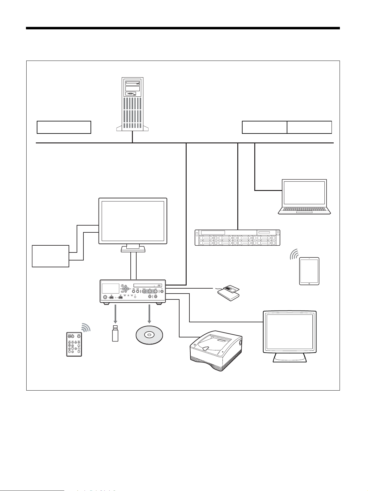
System Configuration Example
File server
Operating room
Endoscopic
device
Doctor’s office ICU
Hospital network
Transmit images from endoscopic
devices and cameras used in the
operating room in real time.
(Streaming)
CMDS-MS10MD / CMDS-MS20MD
Content Management System
Master server
HVO-3300MT
Viewing terminal
iPad application
Card reader/
barcode reader
RM-M010 infrared remote
control unit
Record data to up to
two external storage
media simultaneously.
Touch panel monitor
Printer
19
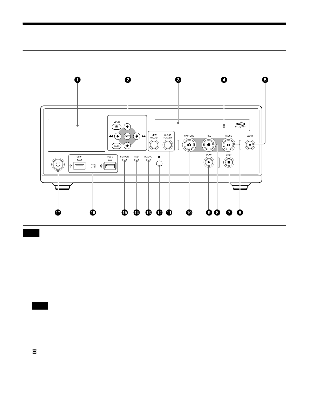
Names and Functions of Parts
Front
Note
Do not touch the laser pickup inside the BD drive
The discharge of static electricity that may result from
touching the pickup may cause the drive to hang up,
preventing the ability to write data. If a hang up occurs,
try turning the recorder off and turning it on again.
a Front panel display
Displays Ch1 input/output videos and still images,
the status of the unit, error messages, etc.
Tip
Even if the output channel is set to Ch2, Ch1 images
will be displayed in the front panel display.
b Menu navigation buttons
Use these to navigate menus.
MENU button
Display or hide the menu.
V button
Use this to move the cursor up or select an item that
is above the current item.
B/m button
Use this to move the cursor left or select an item that
is to the left of the current item.
You can also use this button to rewind during
playback of recorded data.
v button
Use this to move the cursor down or select an item
that is below the current item.
b/M button
Use this to move the cursor right or select an item that
is to the right of the current item.
You can also use this button to fast forward during
playback of recorded data.
ENTER button
Use this to confirm a currently selected menu or item,
and execute operations.
20
When recording or playback is not in progress,
pressing and holding this button for 5 seconds
switches the Ch1 input signal with each long press.
Tip
The signals that are available for switching are the
signals selected in [Ch1 IN Signal Display] in the
[System Admin Settings] screen – [Function
Settings] screen – [Input Signal 2] tab.
BACK button
Use this to return to a previous screen during menu or
operation screen displays.
When you press this button while nothing is
displayed on the screen, the text that appears on the
front panel display will be hidden.
c Disc tray
Insert discs here.
d Emergency eject hole
If the disc tray does not open when you press the Z
EJECT button, insert a long, thin object such as a
straightened paper clip into this hole to open the disc
tray.
recorded data selected in the [Recording List] or
[Image List] screen.
• Press this button while playback is paused to
resume playback.
j CAPTURE button
Use this to capture still images.
A chapter separator is also created at the position in
which the still image was captured.
For details on use, see “Capture Still Images”
(page 50).
k NEW FOLDER button
Use this to display the [Recording Preparation]
screen to start recording a new surgical procedure or
examination.
For details on use, see “Recording Preparation”
(page 45).
CLOSE FOLDER button
Use this to display the [End Recording] screen which
is used to end surgical procedure or examination
recordings.
For details on use, see “Step 4: End Recording”
(page 44).
e Z EJECT button
Use this to open the disc tray.
f X PAUSE button
Use this while recording is in progress to pause
recording. Press this button again to resume
recording. A chapter separator is also created at the
position in which recording was paused.
You can also use this button to pause playback.
To resume playback, press this button again or press
the B PLAY button.
“PAUSE” appears on the front panel display during
pause.
g x STOP button
Use this to stop recording or playback.
A title separator is also created at the position in
which recording was stopped.
h z REC button
Use this to start video/audio recording.
During recording, “REC” appears on the front panel
display in addition to the recording time.
For details on use, see “Manual Recording”
(page 49).
i B PLAY button
• Use this to play back the most recent recorded data
stored on the internal hard disk, or to play back the
l Infrared receiver
Point the infrared remote control unit toward this
receiver.
m BD/DVD indicator
Displays the status of the BD/DVD drive.
Indicator Status
Blinking
green
Lit green The recording area of the BD/DVD disc is
Lit orange An error has occurred.
Note
Data is being written to the BD/DVD disc.
full. Insert a different disc.
You cannot remove the disc when this indicator is
blinking green.
n HDD indicator
Displays the status of the internal hard disk.
Indicator Status
Blinking
green
Lit orange An error has occurred.
Data is being recorded to the internal
hard disk.
The recording area of the internal hard
disk is full. Delete any unnecessary
recorded data.
21
o SERVER indicator
Displays the server access status.
Indicator Status
Blinking
green
Lit orange An error has occurred.
The server is being accessed.
The recording area of the server is full.
p USB ports/indicators 1 and 2
Connect USB memory devices, external hard disks,
and other USB media here.
The indicators display the status of USB media
access.
Indicator Status
Blinking
green
Lit green The recording area of the USB media is
Lit orange An error has occurred.
Note
Data is being written to the USB media.
full. Delete any unnecessary recorded
data, or insert different media.
q 1 (on/standby) switch/indicator
Use this switch to turn on the unit and the front panel
display. Press this switch again to turn off the unit and
enter standby mode.
The indicator indicates the following.
Indicator Status
Off The ? (on) / a (off) switch on the rear
panel is set to the a (off) position.
Lit orange Standby mode. (The ? (on) / a (off)
switch on the rear panel is set to the ?
(on) position.)
Lit green The unit is turned on. (The 1 (on/
standby) switch was pressed to turn on
the unit.)
Tip
The indicator will turn off about 15 seconds after the
? (on) / a (off) switch on the rear panel is turned off
from the standby state.
Never remove USB media when these indicators are
blinking green.
Tip
Supported USB devices
• Use Sony USB media.
• The connectors do not support all USB devices.
• USB hubs and devices with built-in hubs are not
supported.
Warning
Using this unit for medical purposes
The connectors on this unit are not isolated.
Always use USB-compatible external hard drives and
USB memory devices that operate solely on the
power supplied by the unit.
Connecting a device that operates on an AC power
supply may result in an influx of leakage currents
from the connected device, which may in turn result
in electric shocks to the patient and operator.
If use of such devices cannot be avoided, be sure to
connect an isolation transformer to the power supply
of the connected device or connect an isolator
between the connection cables to isolate the power
supply, and verify that the risk of electric shock from
the system has been sufficiently reduced to levels that
conform to IEC 60601-1 standards.
22
Rear
Warning
Using this unit for medical purposes
The connectors on this unit are not isolated.
Do not connect any device other than one which conforms
to IEC 60601-1 standards.
When an information technology device or AV device
that uses an alternating current is connected, current
leakage may result in an electric shock to the patient or
operator.
If use of such a device is unavoidable, isolate its power
supply by connecting an isolation transformer, or by
connecting an isolator between the connecting cables.
After implementing these measures, confirm that the
reduced risk now conforms to IEC 60601-1 standards.
Caution
Do not come into contact with the terminals of the rear
panel connectors and patients at the same time.
Doing so may result in a generation of voltage that can be
harmful to patients if the unit is malfunctioning.
Always disconnect the power cord before connecting and
disconnecting connectors.
a Equipotential grounding terminal
Use this for equipotential grounding connections.
b AC IN connector
Connect a power cord (not supplied) here.
c ? (on) / a (off) switch (main power switch)
Set this to the ? (on) position to turn on the power. To
turn off the power, set the switch to the a (off)
position.
During regular use of the unit, leave the ? (on) / a
(off) switch in the ? (on) position, and use the qj 1
(on/standby) switch on the front panel of the unit to
switch between operational mode and standby mode.
Note
When you press the qj 1 (on/standby) switch on the
front panel of the unit while the unit is in operational
mode, data is saved before the unit enters standby
mode. Always make sure that the unit is in standby
mode before setting the ? (on) / a (off) switch to the
a (off) position to turn off the power.
d AUDIO (analog audio signal) output
connector (stereo mini jack)
Outputs analog audio signals.
e MIC input connector (stereo mini jack)
Inputs analog audio signals from the microphone.
You can configure settings to supply power from the
unit.
23

AUDIO (analog audio signal) input connector
(LINE) (stereo mini jack)
Inputs analog audio signals.
supply, and verify that the risk of electric shock from
the system has been sufficiently reduced to levels that
conform to IEC 60601-1 standards.
f REMOTE contact switch connectors 1 to 4
(stereo mini jack)
Use these to control the unit via contact switches.
Tip
Contact switch connector 4 outputs input signals
from contact switch connector 3 via pass-through,
and returns the status of the pass-through destination.
For details on contact switches, see “[Contact
Switch] Tab” (page 75).
g USB port 7 (Type B / USB 2.0)
Use this to perform system controls from an external
device.
For details, see “[Control] Tab” (page 74).
h Network connector (RJ-45)
Connect a 1000 Base-T or 100 Base-TX network
cable here.
Caution
For safety, do not connect the connector to peripheral
device wiring that might have excessive voltage.
Follow the instructions for use for this port.
i USB ports 3 to 6 (Type A / USB 2.0)
Connect USB devices here.
j MENU MONITOR connector (15-pin mini
D-sub)
Connect a touch panel monitor or similar device here.
k RS-232C connector (9-pin D-sub)
Use this to perform system controls from an external
device.
For details on system controls, see “[Control] Tab”
(page 74).
1 Video I/O block
a DVI-D input connectors 1 and 2 (single link)
Input DVI signals.
The signal from DVI-D input connector 1 is input to
Ch1, and the signal from DVI-D input connector 2 is
input to Ch2.
Tip
Supported USB devices
• Use Sony USB media.
• The connectors do not support all USB devices.
• USB hubs and devices with built-in hubs are not
supported.
Warning
Using this unit for medical purposes
The connectors on this unit are not isolated.
Always use USB-compatible external hard drives and
USB memory devices that operate solely on the
power supplied by the unit.
Connecting a device that operates on an AC power
supply may result in an influx of leakage currents
from the connected device, which may in turn result
in electric shocks to the patient and operator.
If use of such devices cannot be avoided, be sure to
connect an isolation transformer to the power supply
of the connected device or connect an isolator
between the connection cables to isolate the power
b DVI-D output connector (single link)
Outputs DVI signals.
c SDI input connectors 1 and 2 (BNC type)
Input SD-SDI, HD-SDI, or 3G-SDI signals.
The signal from SDI input connector 1 is input to
Ch1, and the signal from SDI input connector 2 is
input to Ch2.
Tips
• If SDI input images are not displayed, turn on the
unit first and make sure that startup is complete
before turning on the video input device.
• Embedded audio is not supported.
d SDI output connector (BNC type)
Outputs SD-SDI, HD-SDI, or 3G-SDI signals.
e VIDEO output connector (BNC type)
Outputs analog composite video signals.
f VIDEO input connector (BNC type)
Inputs analog composite video signals.
24
g RGB input connector (15-pin mini D-sub)
Inputs RGB signals.
h S VIDEO output connector (4-pin mini DIN)
Outputs analog S-Video signals.
You can also use this button to pause playback.
To resume playback, press this button again or press
the B PLAY button.
“PAUSE” appears on the front panel display during
pause.
i S VIDEO input connector (4-pin mini DIN)
Inputs analog S-Video signals.
Infrared Remote Control Unit
(RM-M010)
d m REW button
Use this to rewind during playback of recorded data.
B PLAY button
• Use this to play back the most recent recorded data
stored on the internal hard disk, or to play back the
recorded data selected in the [Recording List] or
[Image List] screen.
• Press this button while playback is paused to
resume playback.
M FF button
Use this to fast forward during playback of recorded
data.
x STOP button
Use this to stop recording or playback.
A title separator is also created at the position in
which recording was stopped.
e NEW FOLDER button
Use this to display the [Recording Preparation]
screen to start recording a new surgical procedure or
examination.
For details on use, see “Recording Preparation”
(page 45).
a CAPTURE button
Use this to capture still images.
A chapter separator is also created at the position in
which the still image was captured.
For details on use, see “Capture Still Images”
(page 50).
b z REC button
Use this to start video/audio recording.
During recording, “REC” appears on the front panel
display in addition to the recording time.
For details on use, see “Manual Recording”
(page 49).
c X PAUSE button
Use this while recording is in progress to pause
recording. Press this button again to resume
recording.
A chapter separator is also created at the position in
which recording was paused.
f CLOSE FOLDER button
Use this to display the [End Recording] screen which
is used to end surgical procedure or examination
recordings.
For details on use, see “Step 4: End Recording”
(page 44).
g Menu navigation buttons
Use these to navigate menus.
MENU button
Display or hide the menu.
v button
Use this to move the cursor down or select an item
that is below the current item.
b button
Use this to move the cursor right or select an item that
is to the right of the current item.
ENTER button
Use this to confirm a currently selected menu or item,
and execute operations.
25
B button
Use this to move the cursor left or select an item that
is to the left of the current item.
V button
Use this to move the cursor up or select an item that
is above the current item.
BACK button
Use this to return to a previous screen during menu or
operation screen displays.
When you press this button while nothing is
displayed on the screen, the text that appears on the
front panel display will be hidden.
Before using the remote control unit
Remove the insulation sheet.
Insulation sheet
Warning
Batteries shall not be exposed to excessive heat such as
sunshine, fire or the like.
Caution
Danger of explosion if battery is incorrectly replaced.
Replace only with the same or equivalent type
recommended by the manufacturer.
When you dispose of the battery, you must obey the law
in the relative area or country.
Battery lifetime
When the lithium battery output falls, even button presses
may not operate. The average lithium battery lifetime is
about one year, but this depends on the pattern of use. If
pressing the remote control buttons produces absolutely
no effect on this unit, replace the battery, then check the
operation again.
Status Displays
The following information is displayed when the status
display settings are enabled.
To replace the lithium battery
Use a Sony CR2025 lithium battery. Do not use any other
type of battery with the remote control unit.
1
While holding in the lock lever (1), pull out the
battery holder (2).
2
Insert the replacement battery with the positive (+)
side facing up (1), and reinsert the battery holder
until it clicks into place (2).
Positive (+) side facing up
The status display settings are configured in the [System
Admin Settings] screen – [Function Settings] screen –
[General 1] tab. For details on this setting, see “[General
1] Tab” (page 69).
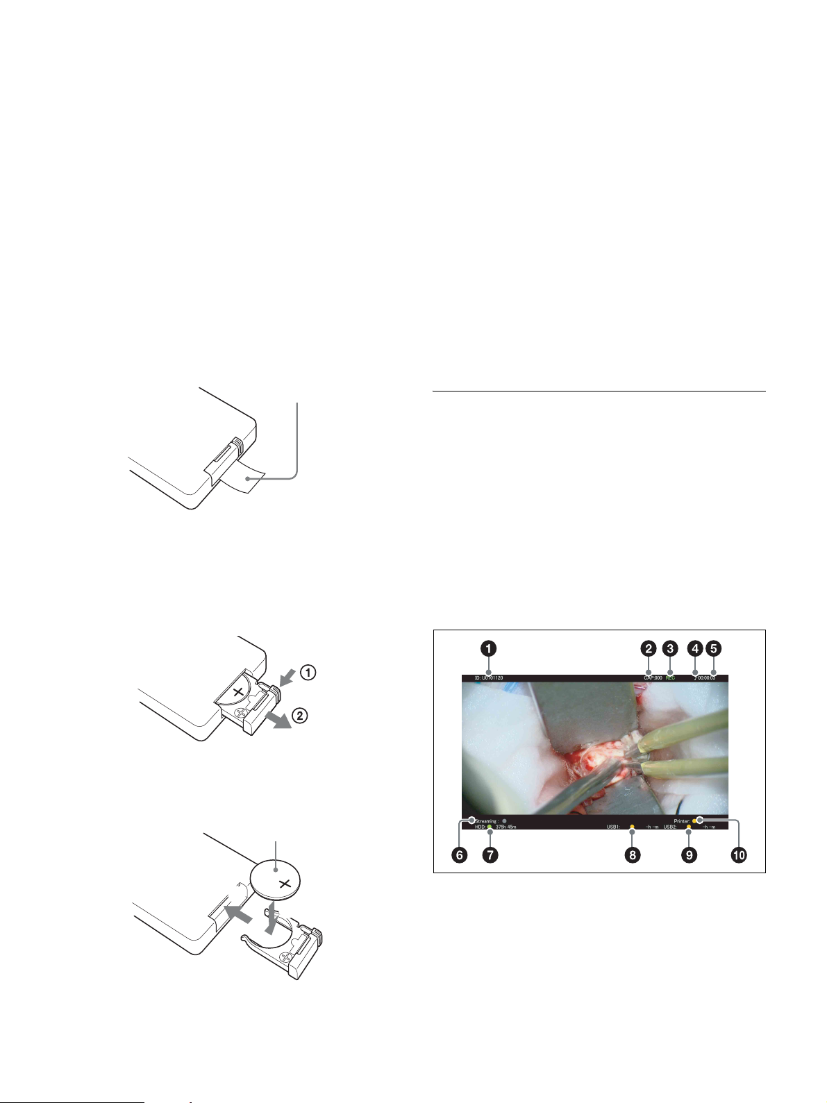
Rec status display / idle status display
Rec status displays
2
1
26
Idle status displays
a Patient ID
Displays the patient ID.
b Capture counter
Displays the number of still images captured.
c Recording status
Displays the recording status.
REC: Recording is in progress.
REC PAUSE: Recording has been paused.
REC STOP: Recording preparation is complete or
recording has been stopped.
Orange: The maximum number of recorded data
entries has been exceeded or the internal HDD is
full.
Gray: Status other than the above.
h [External Storage 1] media status
Displays the status of the external media for [External
Storage 1] and its remaining capacity time.
The status color indicates the following.
• When transferring to BD/DVD
Green: Transfer or formatting is in progress.
Orange: Additional recording to the BD/DVD is
not possible, an unsupported BD/DVD is
inserted, the maximum number of BD/DVD
exchanges has been exceeded, or a finalized
DVD is inserted.
Gray: Status other than the above.
• When transferring to USB
Green: Transfer is in progress.
Orange: An unsupported USB memory device is
inserted, the maximum number of USB
memory device exchanges has been exceeded,
or a transfer error has occurred.
Gray: Status other than the above.
• When transferring to a server
Green: Transfer is in progress.
Orange: Insufficient server capacity or a transfer
error has occurred.
Gray: Status other than the above.
d Audio recording status
Displays the audio recording status.
9: Audio recording is in progress.
no display: Audio is not being recorded.
e Recording time
The recording time is counted in seconds and
displayed in “HH:MM:SS” a format.
f Streaming status
Displays the streaming status.
This is displayed when [Streaming] is set to [Use] in
the [System Admin Settings] screen – [Network
Settings] screen – [Streaming] tab, and [Streaming] is
set to [Stream Ch1 in 2D] or [Stream Ch1 in 3D] in
the [User Settings] screen – [Rec/Streaming] tab.
The status color indicates the following.
Green: Streaming is in progress.
Gray: Streaming is not connected.
g HDD status
Displays the internal HDD status and the remaining
time.
The status color indicates the following.
Green: Recording is in progress or still image
recording is in progress.
i [External Storage 2] media status
Displays the status of the external media for [External
Storage 2] and its remaining capacity time.
The status indications are identical to those for
[External Storage 1].
j Print status
Displays the printer status and the remaining number
of print sheets.
The status color indicates the following.
Green: Still image printing is in progress.
Orange: A print error has occurred.
Gray: Status other than the above.
27
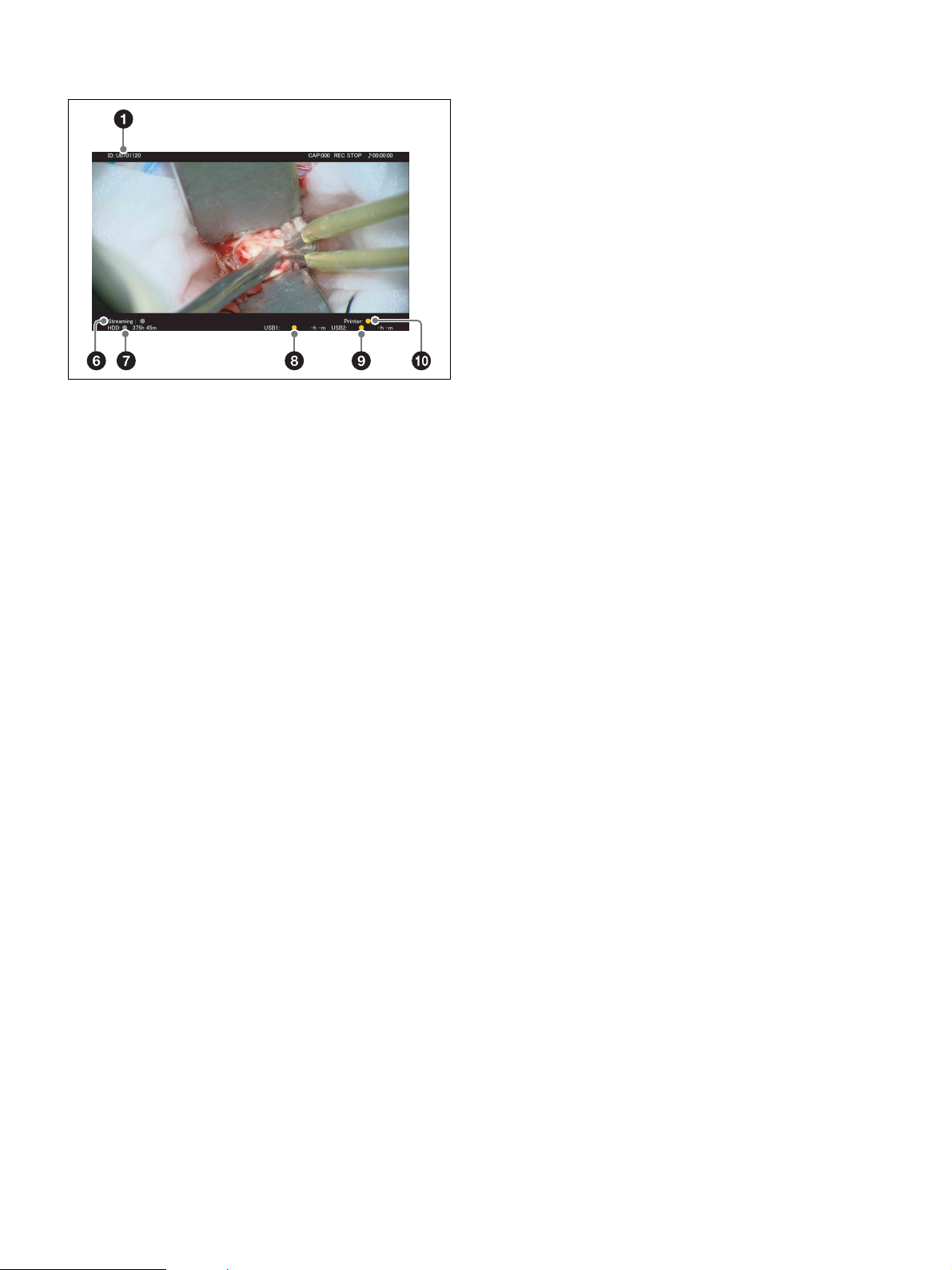
Playback status displays
a Patient ID
b Playback status
Displays the playback status.
PLAY: Video playback is in progress.
FF x2 to FF x60: Fast forward at x2 to x60 speed is
in progress.
REW x2 to REW x60: Rewind at x2 to x60 speed
is in progress.
PAUSE: Playback has been paused.
If either of the two streams for 2-stream 3D images is
not being input, a “No signal” determination is made,
and the signal name will blink.
b External storage media status (1 and 2)
Displays the statuses of external storage media 1 and
2 and their remaining capacity times.
The remaining capacity is not displayed for servers.
c Streaming status
Displays the streaming status.
This is displayed when [Streaming] is set to [Use] in
the [System Admin Settings] screen – [Network
Settings] screen – [Streaming] tab, and [Streaming] is
set to [Stream Ch1 in 2D] or [Stream Ch1 in 3D] in
the [User Settings] screen – [Rec/Streaming] tab.
d Printer status
Displays the status of the USB printer and the
remaining number of print sheets.
For video printers, “
and the status and the remaining number of print
sheets are not displayed.
If a printer is not configured, this item will be grayed
out.
F
Printer:” is displayed in gray,
c Video chapter number / still image playback
status
CHAPTER:xxx/xxx: Displays the number of the
chapter being played back.
STILL:xxx/xxx: Displays the number of the still
image being played back.
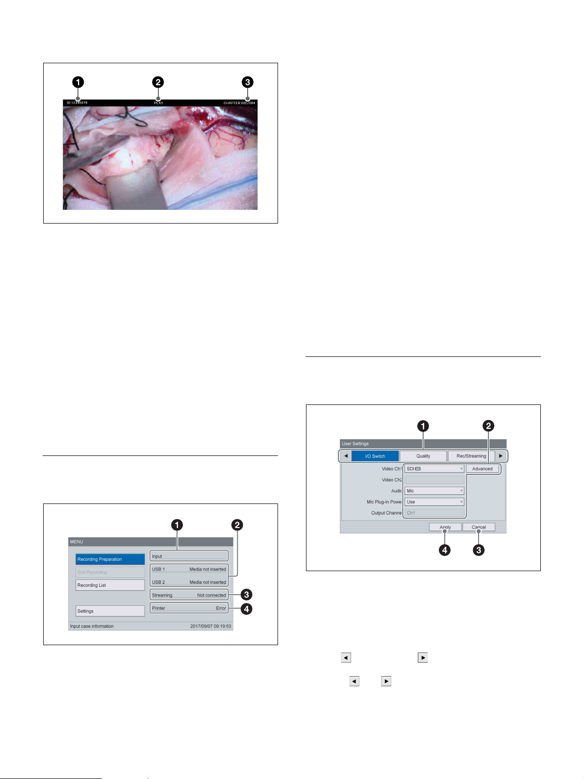
External Device Status Displays
[MENU] screen
a Input signal status
Displays the input signals for Ch1 and Ch2 separated
by a slash (/).
If a signal is not being input, that signal name will
blink at a 1-second interval.
Setting Screens
Example: [User Settings] screen
a Tabs
The setting screens consist of tabs.
To switch between tabs, use the
the front panel or remote control to select the desired
tab.
If additional tabs exist before and after the displayed
tab, (previous) and (next) are also displayed.
The tabs will be displayed in sequence when you
select and .
B and b buttons on
28
b Setting item
Use the
press the ENTER button to display the setting screen
for that item. You can select or enter setting values in
the screens that appear.
V, v, B, and b buttons to select an item, and
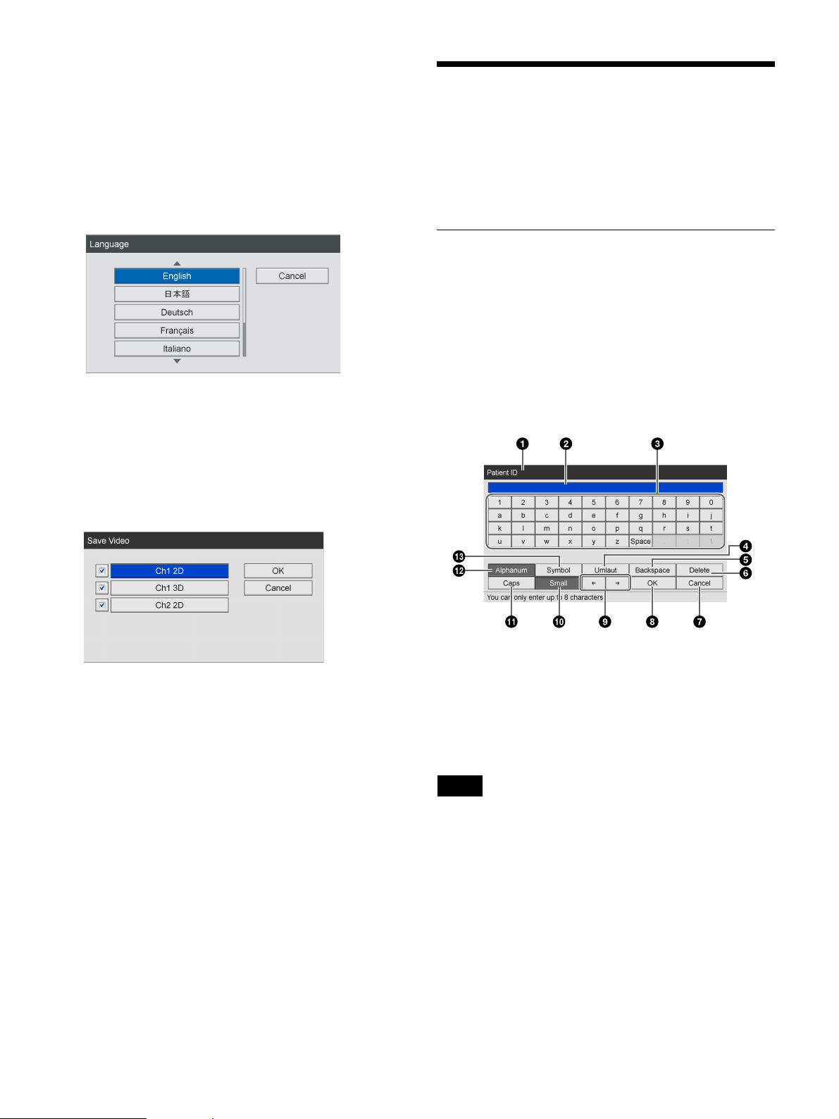
Using the On-Screen Keyboard (Text Entry)
Example: When selecting a setting value
Select the item, and press the ENTER button.
The previous screen will appear again, and the setting
value will be entered.
Example: When selecting check boxes
Select the item and press the ENTER button to select
the check box. The check box will be selected/cleared
with each press of the ENTER button. (Multiple
selections can be made.)
When you select [OK] and press the ENTER button,
the previous screen appears again with the setting
value entered.
When text entry is necessary, an on-screen keyboard
appears.
Names and Functions of Parts (OnScreen Keyboard)
You can display an alphanumeric, symbol, or umlaut
character set on the on-screen keyboard.
The name and function of each part on the keyboard is as
follows.
Example: On-screen keyboard during
alphanumeric character display
c [Cancel]
Select this button and press the ENTER button to
cancel the settings and close the setting screen.
d [Apply]
Select this button and press the ENTER button to save
the settings and close the setting screen.
a Title bar
The name of the setting item for which the on-screen
keyboard was opened is displayed here.
b Entry box
Characters selected on the keyboard are entered here.
Tip
Characters input on a USB keyboard are also entered
here.
c Keyboard
When you select a character you want to input using
the
V, v, B, and b buttons and then press the ENTER
button, the character is entered in the 2 entry box.
d [Umlaut]
Select this and press the ENTER button to switch the
keyboard to umlaut character display.
29
e [Backspace]
Select this and press the ENTER button to discard the
character immediately preceding the cursor.
Handling Discs
f [Delete]
Select this and press the ENTER button to discard the
character immediately following the cursor.
g [Cancel]
Select this and press the ENTER button to cancel text
entry and close the on-screen keyboard.
h [OK]
When you select this and press the ENTER button,
the text that appears in the entry box is applied and
input in the settings screen.
i
B/b
Select this and press the ENTER button to move the
cursor one space to the left or right.
j [Small]
Select this and press the ENTER button to switch the
keyboard to lower case display.
k [Caps]
Select this and press the ENTER button to switch the
keyboard to upper case display.
Compatible discs
This unit supports the following BD and DVD discs.
• DVD-R
•BD-R / BD-R DL
• BD-RE / BD-RE DL
Tip
Use Sony discs.
Disc formatting
This unit automatically formats new and previously
unused discs.
Notes on Handling
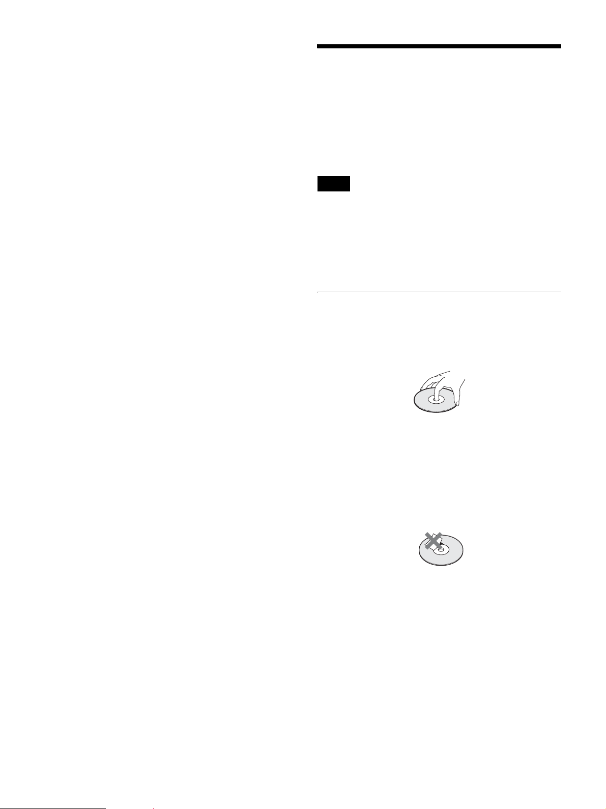
Handling
• Do not touch the recording or playback surface of the
disc. Handle the disc by its edge.
l [Alphanum]
Select this and press the ENTER button to switch the
keyboard to alphanumeric character display.
m [Symbol]
Select this and press the ENTER button to switch the
keyboard to symbol display.
• Do not use the following types of disc. Doing so may
cause the unit to malfunction.
– A disc on which a paper label or a seal is attached
– A disc on which the glue of cellophane tape or a label,
or on which a portion of a label still remains
– A cracked disc
– A cracked disc which has been mended using glue (or
a similar substance)
Storage
• Do not store discs where they may be subjected to direct
sunlight, or in other places where the temperature or
humidity is high.
• Store discs in their cases.
• Finger prints or dust accumulated on the disc cause
deterioration of picture quality. Keep the disc clean.
30
 Loading...