

Sony HS-KP1 User Manual
4-113-748-11(2)
White/Orange
Wire color
Orange
White/Green
Blue
White/Blue
Green
White/Brown
Brown
1
Pin No.
2
3
4
5
6
7
8
ZONE
MODE
DC IN
+19.5V GND
R
+
RLL
+
SPEAKERS
IMPEDANCE USE
8 - 16
HT
IR REMOTE
IN
a b
A
B
C
D
ZONE
MODE
DC IN
+19.5V GND
R
+
RLL
+
SPEAKERS
IMPEDANCE USE
8 - 16
HT
IR REMOTE
IN
HS-WA1
TO LOCAL AUDIO
WALL PORT
HS-WV1
TO DISTRIBUTION PANEL
HS-MB1
TO AV WALL PORT
Connecting speaker cords or power supply cords
You can connect up to two Keypads directly to a Power Supply (HS-AC1) in order to improve sound coverage of
the Keypad. For details on Power Supply connection, refer to HS-AC1 manual.
You can use any commercially available cord of gauge AWG 18 to AWG 26. AWG 18 cords are recommended as
signal loss is less.
Keypad
This manual is for installers only.
Contact your nearest installer for details on making the required connections for the system network.
Before installation, refer to “System network” in the operating instructions of the Keypad to understand the
wiring needed for the system.
Installer’s manual
HS-KP1
(2)
©2008 Sony Corporation Printed in Malaysia
Precautions
Caution
Unauthorized substitutions may result in fire, electric shock, or cause serious injury or death.
Keep the following precautions in mind to prevent any accidents.
Installment other than specified in the instructions may cause the unit to fall due to lack of wall strength.
Do not use screws other than the supplied screws for installation.
Do not install the unit following any procedure other than that explained in this manual. Make sure to follow
the procedure in this manual closely.
Do not disassemble the unit. Disassembly may cause a malfunction or cause injury.
Do not place excessive pressure on the unit after mounting it. Damage may result, or it may cause injury.
CAUTION
RISK OF EXPLOSION IF BATTERY IS REPLACED BY AN INCORRECT TYPE.
DISPOSE OF USED BATTERIES ACCORDING TO THE INSTRUCTIONS
On power sources
If you are not going to use the unit for a long time, be sure to disconnect the unit from the wall outlet. To
disconnect the AC power cord, grasp the plug itself; never pull the cord.
On placement
The unit is designed for mounting only on the wall. You cannot mount it on the ceiling or on the floor.
Place the unit in a location with adequate ventilation to prevent heat build-up in the unit.
Do not place the unit on a soft surface, such as a rug.
Do not place the unit near heat sources, or in a place subject to direct sunlight, excessive dust, or mechanical
shock.
Do not install the unit in an inclined position. It is designed to be operated in a vertical position only.
Keep the unit away from equipment with strong magnets, such as microwave ovens, or large loudspeakers.
Do not install the unit in a humid location, such as in a bathroom, or a place where moisture condensation may
occur. Install the unit in a place where the environment falls within the operating temperature 0°C – 30°C
(32°F – 86°F).
Do not step on or place heavy objects on the unit. Damage may result, or it may cause injury.
Installation into the wall should be done by Qualified Technicians.
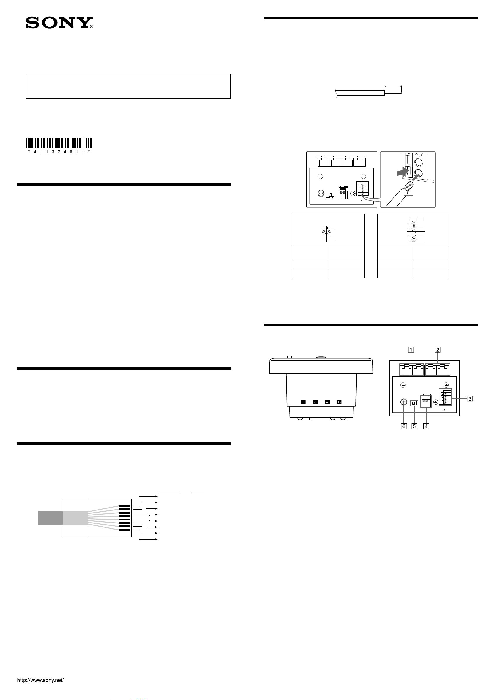
1 Strip 10 mm (0.4 inches) of insulation off the cords and twist the
bare wires together tightly.
Be sure that the length of the bare wires is 10 mm (0.4 inches), matching the full-size illustration below.
10 mm (0.4 inches)
Note
Do not use a cord that is kinked, tarnished or otherwise damaged.
2 While pressing down the orange tab next to the terminal, insert
the cord into the terminal as far as it will go. See the tables below
for connections.
Rear of the unit
Cord
This unit
DC IN
DC 19.5 V – a
GND – b
Notes
To press down the orange tab, a slim object such as a flathead screwdriver can be used.
Be sure to connect the terminals correctly as shown in the table above. If a speaker cord is reversed, the
sound may be distorted.
Make sure none of the bare wires touch each other. If they do, it may cause a short-circuit, which could
damage the system.
Power Supply
DC OUT
19.5 V
GND
This unit Your speakers
R+/- – A/B
L-/+ – C/D
R+/-
L-/+
Part names and descriptions
Top of the unit
Rear of the unit
Unpacking
HS-KP1 (1)
Operating Instructions (1)
Remote commander (1)
R6 (size-AA) batteries (2)
Installer’s manual (this manual) (1)
Wall mounting bracket (1)
Screws for the wall mounting bracket (long) (4)
Screws for the unit (short) (2)
The other units referred to in this manual are optional. Prepare necessary units depending on your system.
Connecting RJ45 connectors to CAT5 cables
Before you connect the CAT5 cables to the unit, you need to connect the RJ45 connectors to each end of the
cables.
Be sure to use Category 5e straight-through cables, and the wiring connection is correct. See the illustration below
for details on connections.
CAT5 cable
Note on installing CAT5 cables
The following lengths of cable(s) can extend up to 200 feet:
The combined length of the two longest cables connecting the Distribution Panel (HS-MB1) to an AV Wall Port
(HS-WV1) and a Keypad (this unit).
The length of cable connecting an AV Wall Port (HS-WV1) directly to a Keypad (this unit) without connecting
the Distribution Panel (HS-MB1).
The length of cable connecting a Local Audio Wall Port (HS-WA1) to a Keypad (this unit).
RJ45 terminals (, )
Connect the unit to Local Audio Wall Port (HS-WA1) using CAT5 cables so that the letters (, ) indicated
on both the units match each other.
RJ45 terminals (, )
Connect the unit to Distribution Panel (HS-MB1) or AV Wall Port (HS-WV1) using CAT5 cables so that the
letters (, ) indicated on both the units match each other.
SPEAKERS
Connect speakers (nominal impedance 8 ohms or higher) in a room using a speaker cord. See “Connecting
speaker cords or power supply cords.”
DC IN
Connect DC IN of Keypad to DC OUT of Power Supply (HS-AC1) using a power supply cord. See
“Connecting speaker cords or power supply cords.” A DC power source is supplied to the Keypad through the
AWG 24 cords inside the CAT5 cable connected to . However, sound quality of the Keypad may deteriorate
if cables are long, due to power loss through the cable. For optimum sound quality, connect directly Keypad
and Power Supply using thicker cords than AWG 24, up to AWG 18.
MODE (ZONE/HT) switch
Switch between ZONE mode and HT mode. The ZONE mode is used to select input sources. The HT mode
can be used for basic operations on the Multi Channel AV receiver. For further details on these modes, refer to
the Keypad operating instructions.
IR REMOTE IN
Connect an IR sensor.
Installing the Unit
Before installing the unit into the wall, take steps to ensure your safety and that of your surroundings. Check the
following:
You can connect speakers (nominal impedance 8 ohms or higher) to the unit. For details, see “Connecting
speaker cords or power supply cords.”
The necessary wiring such as CAT5 cables, speaker cords, power supply cords, or IR REMOTE cords varies
depending on your system.
The location of the speakers to make sure that speaker cords can be run between the unit and the speakers.
The durability of the wall. The thickness of the wall must be between 13 to 19 mm (1/2 to 3/4 inches).
There are no obstructions, such as air, electrical, or water conduit near the location where the unit is installed.
There is enough space (over 15 cm (6 inches)) inside the wall. If the space available inside the wall is insufficient
or does not have proper ventilation, a malfunction of the unit may occur due to heat build-up.
Do not install the unit where it may get wet due to water or other liquids. This may cause a malfunction of the
unit.
Do not install the unit in a place where moisture condensation may cause a malfunction of the unit.
Installing a 2 gang J-box in a new construction
Be sure to install a 2 gang J-box on a stud before wall construction is finished, so that the unit can be placed in the
2 gang J-box after construction of the wall is finished.
Sony recommends:
Carlon gang boxes
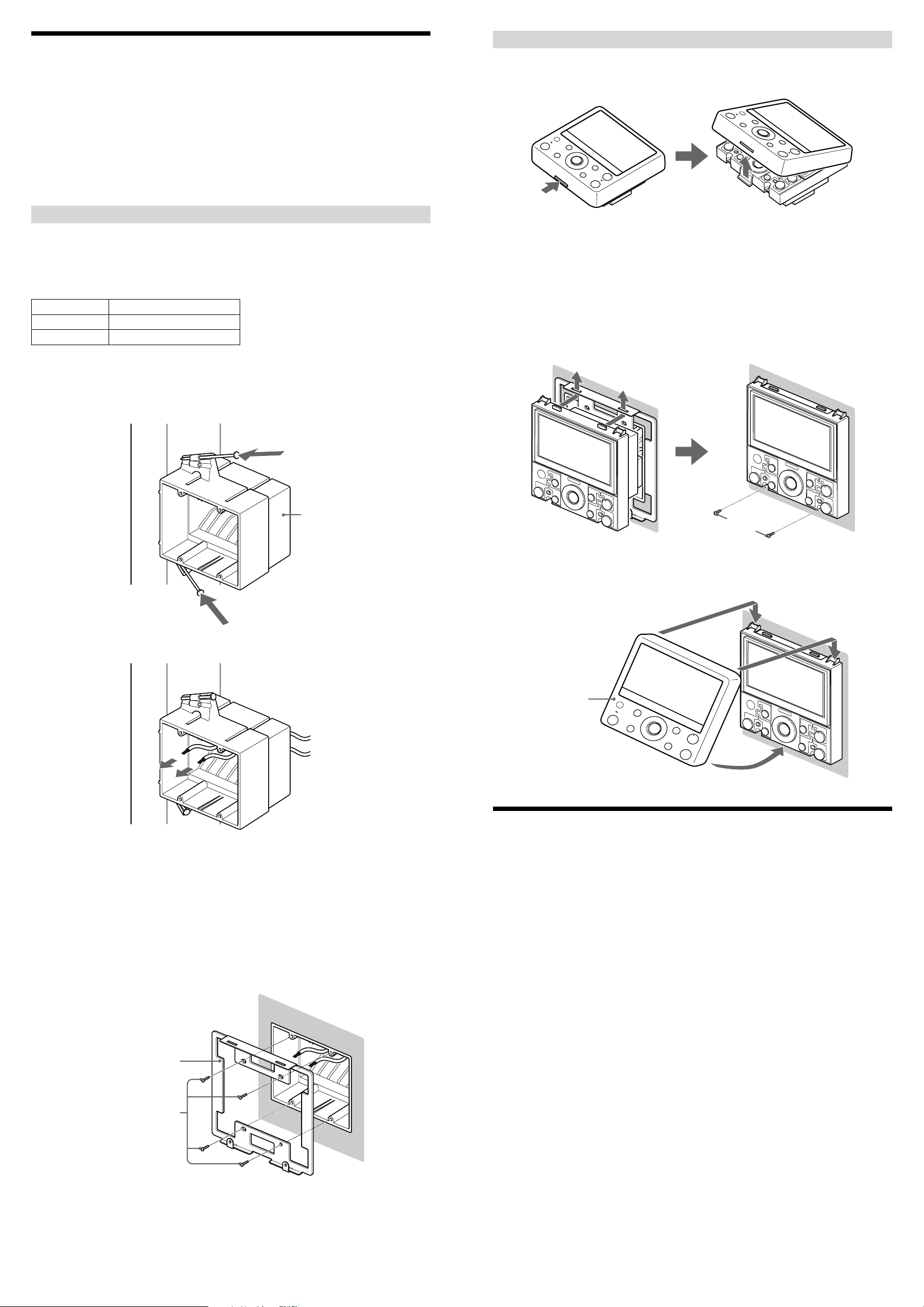
Connecting the cables and installing the unit into the wall
1 While pushing the tab at the bottom of the unit, remove the cover
panel. (The cover panel and unit are factory-packed separately.)
2 Attach RJ45 connectors to the ends of the CAT5 cables.
For details, see “Connecting RJ45 connectors to CAT5 cables.”
3 Connect the units using the CAT5 cables.
For details, see “Connecting speaker cords or power supply cords” and “Part names and descriptions.”
Part No. Description
BH235A, SC200A 2 gang J-box with nails
BH235S 2 gang J-box with screws
1 Prewire the CAT5 cables in the walls.
2 Place the 2 gang J-box on a stud, and then fasten it with the nails
or screws that came with the 2 gang J-box.
2 gang J-box
4 Insert the rear of the unit into the 2 gang J-box, and insert the two
tabs on the top of the unit into the holes of the wall mounting
bracket. Then fasten the bottom part of the unit with the screws
(supplied) with the wall mounting bracket.
Screws for the unit (short)
5 Hook the cover panel on the two tabs on the top of the unit first,
and then push the bottom part until the panel clicks into place.
3 Run the CAT5 cables through the holes of the 2 gang J-box.
Note
Do not pull the cable in longer than necessary. The unit may not be placed in the 2 gang J-box because of the
extra length of the cable.
4 Cut a hole of 110 to 116 mm (4
3
/8 to 4 5/8 inches) in width and 98
to 104 mm (3 7/8 to 4 1/8 inches) in length in the wall material. Then
attach it to the structure of the house, and finish the wall.
5 Place the wall mounting bracket (supplied) in the hole of the
finished wall, and then fasten it with screws (supplied) to the 2
gang J-box.
Wall mounting bracket
Screws for the wall
mounting bracket (long)
Cover panel
Specifications
LCD
4.3 inch color TFT
GUI/NTSC for Camera and Monitor
Intercom
Push to talk
Mic: Monaural
Speaker: Monaural
Audio
Rated Output Power at 2ch stereo (8 ohms 1 kHz, THD: 10%): 20 W + 20 W (Optimum performance*)
* Depending on the length of the CAT5 (Category 5e) cable connected to of the rear panel, or the length of
diameter of the cable connected to DC IN of the rear panel.
Input and Output connectors
RJ45: (only for connection to HS-MB1 (Distribution Panel) or HS-WV1 (AV Wall
Port))
(only for connection to HS-WA1 (Local Audio Wall Port))
Speaker output: Wire requirements: Copper Wire AWG 26 – 18
Outer diameter: 3 mm (0.12 inches), maximum
Strip away: 10 mm (0.4 inches)
DC IN: Wire requirements: Copper Wire AWG 26 – 18
Outer diameter: 3 mm (0.12 inches), maximum
Strip away: 10 mm (0.4 inches)
IR IN: Monaural mini-jack (ø 3.5 mm)
General
Power supply: DC 19.5 V (only HS-AC1 (Power Supply))
Power consumption: DC 19.5 V/0.5 A (when driving the 8-ohm speaker)
Operating temperature: 0 °C - 30 °C (32 °F - 86 °F)
Dimensions: 134 × 134 × 80 mm (5 3/8 × 5 3/8 × 3 1/4 inches) (w/h/d)
Mass: 450 g (1 lbs 15 6/8 oz)
Design and specifications are subject to change without notice.
 Loading...