

Sony HKDW-704 Installation And Maintenance Manual

GPS UNIT
HKDW-704
INSTALLATION AND MAINTENANCE MANUAL
1st Edition
! WARNING
This manual is intended for qualified service personnel only.
To reduce the risk of electric shock, fire or injury, do not perform any servicing other than that
contained in the operating instructions unless you are qualified to do so. Refer all servicing to
qualified service personnel.
! WARNUNG
Die Anleitung ist nur für qualifiziertes Fachpersonal bestimmt.
Alle Wartungsarbeiten dürfen nur von qualifiziertem Fachpersonal ausgeführt werden. Um die
Gefahr eines elektrischen Schlages, Feuergefahr und Verletzungen zu vermeiden, sind bei
Wartungsarbeiten strikt die Angaben in der Anleitung zu befolgen. Andere als die angegeben
Wartungsarbeiten dürfen nur von Personen ausgeführt werden, die eine spezielle Befähigung
dazu besitzen.
! AVERTISSEMENT
Ce manual est destiné uniquement aux personnes compétentes en charge de l’entretien. Afin
de réduire les risques de décharge électrique, d’incendie ou de blessure n’effectuer que les
réparations indiquées dans le mode d’emploi à moins d’être qualifié pour en effectuer d’autres.
Pour toute réparation faire appel à une personne compétente uniquement.
HKDW-704

Section 1
Installation
1-1. HKDW-704 Configuration
The HKDW-704 consists of the following:
. GPS antenna (150)/(5000) (Each one) (150) = 150 mm, (5000) = 5 m
. Connection cord (GPS remote control cable) (1)
Connection cable to connect the Camcorder REMOTE terminal and PC (in which map software is
installed.) (Refer to Operation Manual for details.)
. GPS-SS harness (1)
. GPS F cover (1)
. GPS handle plate (1)
. GPS antenna tape (Velcro fastening) (1)
. F cover bracket (1)
. Harness clamp (1)
. GPS module (including CN connector RF cable) (1)
. FCC mark label (1)
. GPS module clamp (1)
. Precision screw +P2.6 x 10 (4)
. Washer W2.6 (2)
. Operation manual (1)
. Installation and maintenance manual (1)
In addition to the Installation and Maintenance Manual, the following manuals are available.
HKDW-704 Operation Manual (Supplied with HKDW-704)
This manual is necessary for application and operation of the HKDW-704.
HDW-730/750/750P/750CE Operation Manual (Supplied with HDW-730/750/750P/750CE)
MSW-900/900P Operation Manual (Supplied with MSW-900/900P)
These manuals are necessary for application and operation of the HDW-730/750/750P/750CE and MSW900/900P.
HDW-750/750P/750CE/730, HKDW-702/703 Maintenance Manual Volume 1/Volume 2
(Available on request)
MSW-900/900P, MSDW-902/903/904 Maintenance Manual Volume 1/Volume 2
(Available on request)
These manuals are intended for use by trained system and service engineers, and describe the information
(Volume 1 : parts replacement, adjustment procedure, etc., Volume 2 : parts list, circuit diagram, etc.) on
the premise of component level service.
For obtaining, contact your local Sony Sales Office/Service Center.
HKDW-704
1-1 (E)

1-2. Confirming Display before Installation and Starting to Use
1-3. Modification of SS-92 Board
1-2. Confirming Display before Installation and Starting to Use
To install the HKDW-704 in the HDW-750/750P/750CE/730 and the MSW-900/900P, the ROM that is
installed in the AT-143 board and the SS-92 board must have been upgraded to the versions that support
HKDW-704.
Before installation and operation, confirm that the UMID SET display appears with the use of the OPERATION menu of the HDW-750/750P/750CE/730 and the MSW-900/900P. If the UMID SET display
does not appear, upgrade the ROM that is installed in the AT-143 board and the SS-92 board.
(For upgrading, refer to Maintenance Manual Volume 1 “1-24. Upgrading the ROM Version” of the
HDW-750/750P/750CE/730 and the MSW-900/900P.)
1-3. Modification of SS-92 Board
When the SS-92 board of the main unit has the part No. suffix-12, install the following parts in order to
support GPS.
Parts required
Name Sony part No. Q’ty
CONDUCTOR, CHIP (1608) 1-216-864-91 1
Connect the above component in between CL2 and CL3 (C-2/A side) on the SS-92 board (suffix-12) by
soldering.
1-2 (E)
HKDW-704
1-4. Installation Procedure
Outline of installing the HKDW-704 to the HDW-750/750P/750CE/730 and the MSW-900/900P is listed
as follows. For the details of the installation work, refer to the respective sections.
Installation procedure Section describing the detailed procedure
1. Confirming that the UMID SET display appears. 1-2. Confirming Display before Installation and Starting to
Use
2. Removing the viewfinder “5-2. Adjusting the Viewfinder ” of Operation Manual of the
main unit.
3. Removing the inside panel assembly 1-5. Removing and Reinstalling the Inside Panel Assembly
4. Removing the DCP board assembly 1-6. Removing and Reinstalling the DCP Board Assembly
5. Removing the DVP board assembly 1-7. Removing and Reinstalling the DVP Board Assembly
6. Removing the handle assembly 1-8. Removing and Reinstalling the Handle Assembly
7. Installing the GPS-SS harness 1-9. Installing the GPS-SS Harness
1-10. Wiring Cables to the Handle Assembly
8. Installing the GPS module 1-11. Installing the GPS Module
9. Reinstalling the DVP board assembly 1-7. Removing and Reinstalling the DVP Board Assembly
10. Reinstalling the DCP board assembly 1-6. Removing and Reinstalling the DCP Board Assembly
11. Reinstalling the Inside panel assembly 1-5. Removing and Reinstalling the Inside Panel Assembly
12. Reinstalling the viewfinder “5-2. Adjusting the Viewfinder ” of Operation Manual of the
main unit.
13. Reinstalling the GPS antenna 1-12. Installing the GPS Antenna
14. Operation check
1 Turn on the power of the main unit once. Wait until
the system becomes operable. Then turn the power
back off. (The reboot is required to recognize the GPS
module installed.)
2 Turn on the power again and confirm that the GPS (Refer to the HKDW-704 Operation Manual.)
SET UP display appears and the time indication . Setting
appears in the REAL item on the GPS INFORMA- . To display the GPS INFORMATION screen.
TION display, with the use of the OPERATION menu
of the main unit.
1-4. Installation Procedure
n
This manual is described on the premise of installing the HKDW-704 in the HDW-750/750P/750CE/730.
When the HKDW-704 is going to be installed in the MSW-900/900P, substitute the board names of the
HDW-750/750P/750CE/730 with the corresponding board names of the MSW-900/900P as shown below.
HDW-750/750P/750CE/730 MSW-900/900P
DVP-18 → DVP-20
DCP-28 → DCP-35
FP-121 → FP-121A
HKDW-704
1-3 (E)
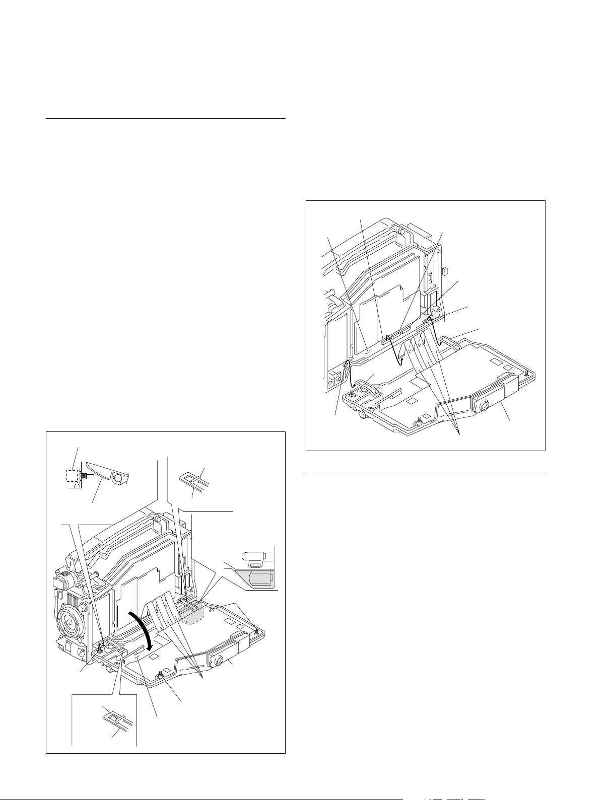
1-5. Removing and Reinstalling the Inside Panel Assembly
1-5. Removing and Reinstalling the
Inside Panel Assembly
Removal
m
. Be sure to set the POWER switch to OFF, unplug the
power cord or remove the battery before starting any of
the following procedure to protect inside of the unit from
damage.
. Insert a piece of paper between the hinge and the
connector box to prevent connector box from damaging
as it contacts with hinge.
(HDW-750 : Applicable to serial No. 70001 and higher
or only when HKDW-702 is installed.)
1. Loosen the four screws (with drop-safe) and open the
inside panel assembly in the direction of the arrow.
m
. The flexible card wire that is connected to the FP-
121 board, will be significantly shortened its life if it
is folded. Be very careful not to fold the flexible
card wire.
. Stand the unit in the posture that the POWER switch
side faces upward when the inside panel assembly is
opened.
POWER switch
2. Disconnect the flexible card wires from the connectors
(CN105 to CN107) on the MB-898 board.
n
Life of flexible card wire will be significantly shortened if it is folded. Be very careful not to fold the
flexible card wire.
3. Disengage the hinge from the two hooks and remove
the inside panel assembly from the unit.
CN105
MB-898
board
Hinge
Hook
CN106
CN107
Hook
Hinge
Inside panel
Flexible card wires
Inside panel
assembly
Screw
(with drop-safe)
Hook
Hinge
Hinge
Flexible
card wires
Screw (with drop-safe)
FP-121 board
Hook
Insert a piece of paper
into the protection block.
(Only when the connector
box is installed.)
Screws
(with drop-safe)
Inside panel
assembly
Reinstallation
1. Check that the hinges in the right and left are engaged
securely with the hooks of the chassis.
2. Connect the flexible card wire to the connector on the
MB-898 board.
3. Insert the inside panel assembly and tighten the four
screws (with drop-safe).
n
Standard tightening torque :
Screw (with drop-safe, B3 x 12)
80 x 10_2 N.m (8 kgf.cm)
n
Be careful not to pinch the harness between the inside
panel assembly and the chassis.
1-4 (E)
HKDW-704
 Loading...