

Sony HCD-MD555 Service manual
HCD-MD555
SERVICE MANUAL
Ver 1.1 2001. 08
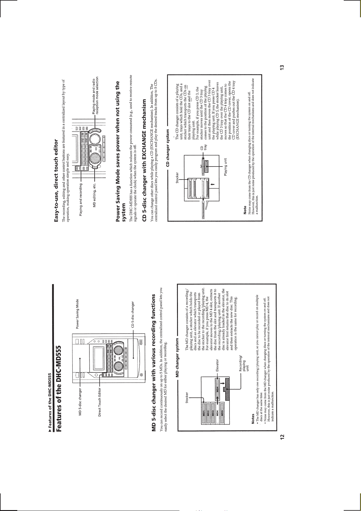
• This set is the Amplifier, CD pla yer ,
MD Deck and Tuner section in
DHC-MD555.
Manufactured under license from Dolby Laboratories
Licensing Corporation.
“DOLBY” the double-D symbol a “AC-3” and “PRO
LOGIC” are trademarks of Dolby Laboratories
Licensing Corporation.
CD Section CD Mechanism Type CDM53-K1BD33
MD Section
US Model
AEP Model
UK Model
E Model
Tourist Model
Model Name Using Similar Mechanism NEW
Optical Pick-up Type
Model Name Using Similar Mechanism NEW
MD Mechanism Type MDM-C1E
Base Unit Type MBU-C1E
Optical Pick-up Type KSM-260A/J1N
KSM-213BFN/C2NP
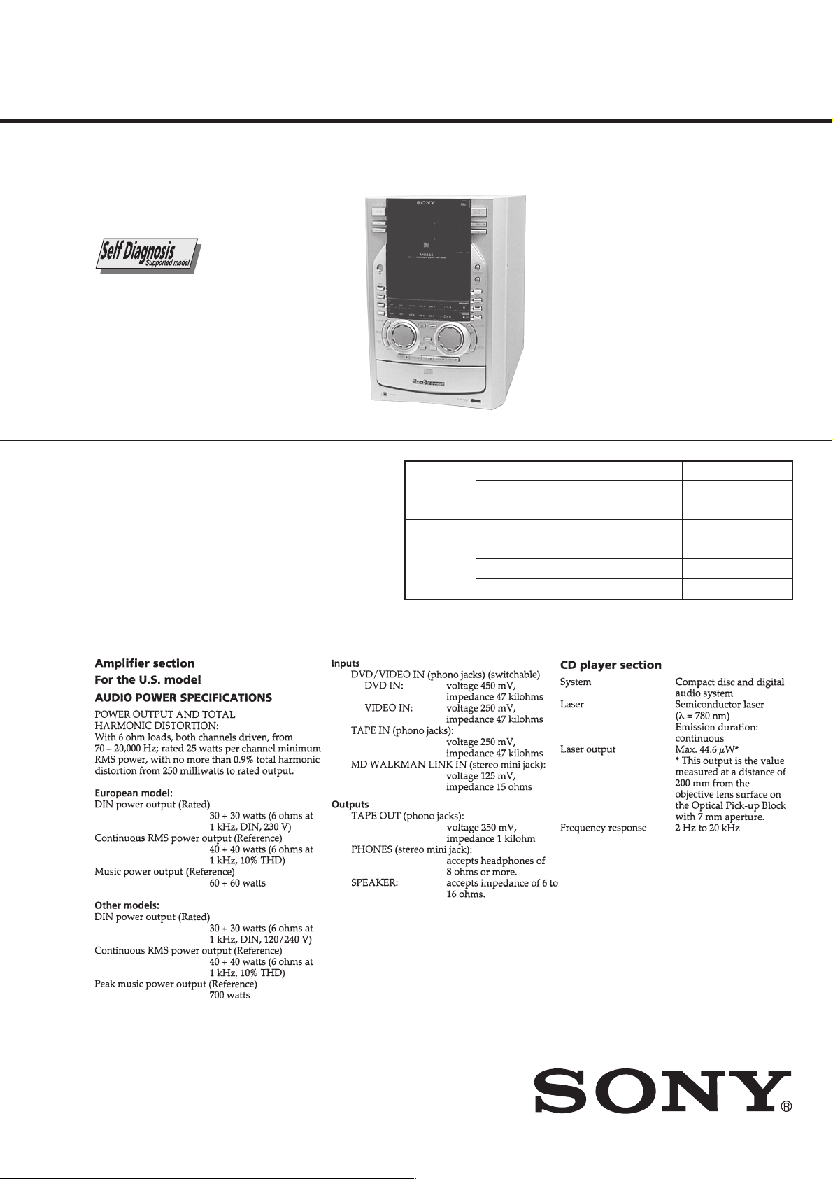
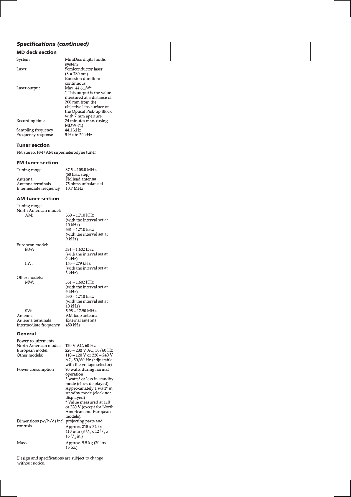
SPECIFICATIONS
MINI Hi-Fi COMPONENT SYSTEM
— Continued on next page —
9-922-976-12
2001H1600-1
© 2001.8
Sony Corporation
Home Audio Company
Shinagawa Tec Service Manual Production Group
NOTES ON HANDLING THE OPTICAL PICK-UP
BLOCK OR BASE UNIT
The laser diode in the optical pick-up block may suffer electrostatic
break-down because of the potential difference generated by the
charged electrostatic load, etc. on clothing and the human body.
During repair, pay attention to electrostatic break-down and also
use the procedure in the printed matter which is included in the
repair parts.
The flexible board is easily damaged and should be handled with
care.
NOTES ON LASER DIODE EMISSION CHECK
The laser beam on this model is concentrated so as to be focused on
the disc reflective surface by the objective lens in the optical pickup block. Therefore, when checking the laser diode emission,
observe from more than 30 cm away from the objective lens.
Notes on chip component replacement
• Never reuse a disconnected chip component.
• Notice that the minus side of a tantalum capacitor may be damaged by heat.
Flexible Circuit Board Repairing
• Keep the temperature of the soldering iron around 270 ˚C during repairing.
• Do not touch the soldering iron on the same conductor of the
circuit board (within 3 times).
• Be careful not to apply force on the conductor when soldering
or unsoldering
— 2 —
SAFETY-RELATED COMPONENT WARNING!!
COMPONENTS IDENTIFIED BY MARK ! OR DO TTED LINE WITH
MARK ! ON THE SCHEMATIC DIAGRAMS AND IN THE PARTS
LIST ARE CRITICAL TO SAFE OPERATION. REPLACE THESE
COMPONENTS WITH SONY PARTS WHOSE PART NUMBERS
APPEAR AS SHOWN IN THIS MANUAL OR IN SUPPLEMENTS
PUBLISHED BY SONY.
CAUTION
Use of controls or adjustments or performance of
procedures other than those specified herein may
result in hazardous radiation exposure.
SAFETY CHECK-OUT
After correcting the original service problem, perform the following
safety check before releasing the set to the customer:
Check the antenna terminals, metal trim, “metallized” knobs, screws,
and all other exposed metal parts for AC leakage.
Check leakage as described below.
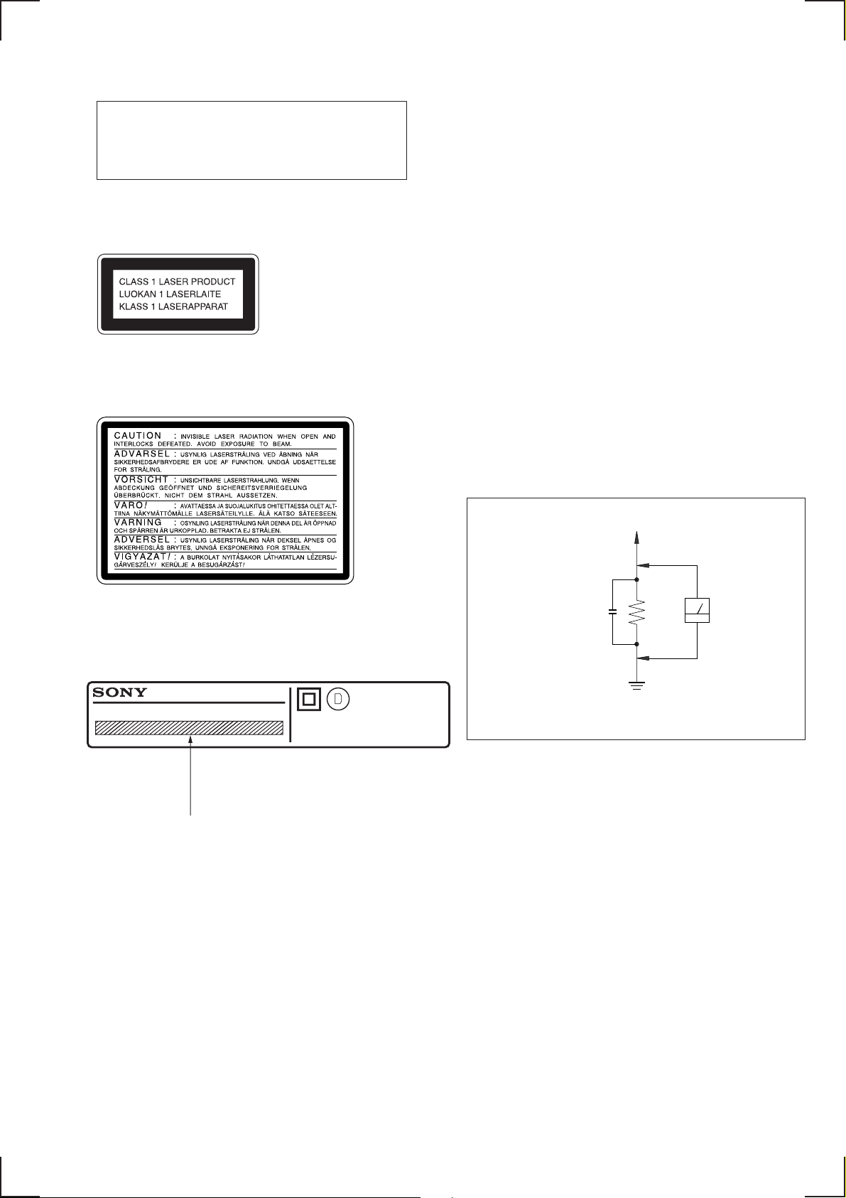
This appliance is classified as a CLASS 1 LASER product.
The CLASS 1 LASER PRODUCT MARKING is located on
the rear exterior.
Laser component in this product is capable of emitting radiation
exceeding the limit for Class 1.
The following caution label is located inside the unit.
LEAKAGE TEST
The AC leakage from any exposed metal part to earth ground and
from all exposed metal parts to any exposed metal part having a
return to chassis, must not exceed 0.5 mA (500 microampers.).
Leakage current can be measured by any one of three methods.
1. A commercial leakage tester, such as the Simpson 229 or RCA
WT-540A. Follow the manufacturers’ instructions to use these
instruments.
2. A battery-operated AC milliammeter. The Data Precision 245
digital multimeter is suitable for this job.
3. Measuring the voltage drop across a resistor by means of a V OM
or battery-operated A C voltmeter . The “limit” indication is 0.75
V, so analog meters must have an accurate low-voltage scale.
The Simpson 250 and Sanwa SH-63Trd are examples of a
passive V OM that is suitable. Nearly all battery operated digital
multimeters that have a 2 V A C range are suitable. (See Fig. A)
To Exposed Metal
Parts on Set
AC
0.15µF
1.5k
Ω
voltmeter
(0.75V)
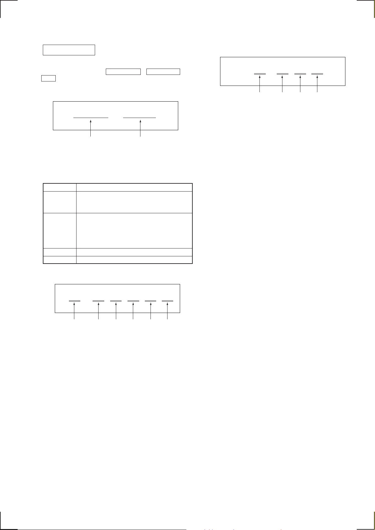
MODEL IDENTIFICATION
– BACK PANEL –
MODEL NO.
COMPACT DISC DECK RECEIVER
AC: 230V ~ 50/60Hz 90W: AEP, UK model
AC: 110 – 120/220 – 240V ~ 50/60Hz 90W
: Singapore, Malaysia, Hong Kong, Tourist model
AC: 120V 60Hz 90W: US model
HCD-MD555
SERIAL
MADE IN
NO.
Earth Ground
Fig. A. Using an AC voltmeter to check AC leakage .
JAPAN
— 3 —

TABLE OF CONTENTS
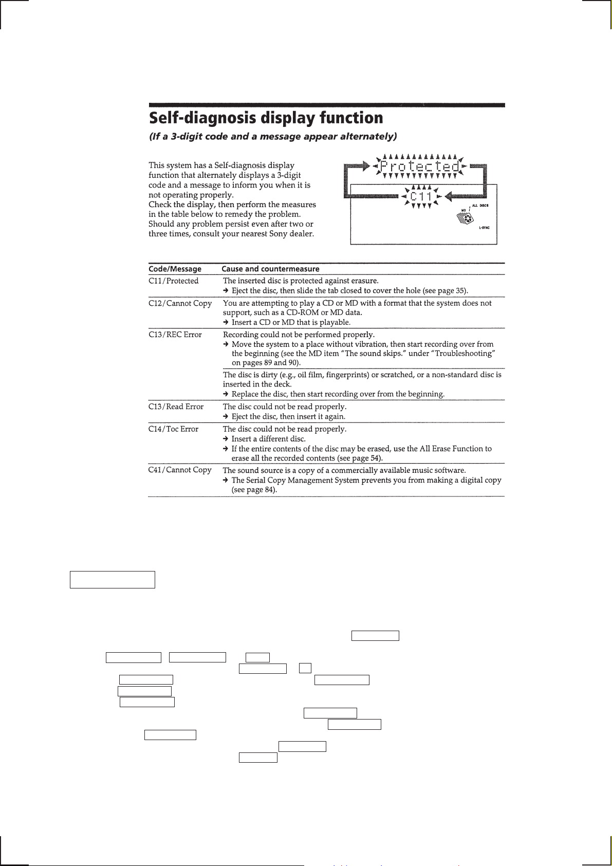
1. SELF-DIAGNOSIS FUNCTION·································· 5
2. SERVICE NOTE·······························································8
3. GENERAL ········································································ 12
4. DISASSEMBLY
4-1. Back Panel········································································ 25
4-2. Mechanism (MDM-C1E) ················································· 25
4-3. SP Board, Amp Board, Reg Board ··································· 26
4-4. Front Panel ······································································· 26
4-5. Power Key Board, LED Board, Panel Board ··················· 27
4-6. Power Transformer (T960), Trans-A/B/C/D Board ········· 27
4-7. CD Mechanism (CDM53-K1BD33) ································ 28
4-8. Escutcheon, Chassis (Top) ··············································· 29
4-9. Chassis (Elevator) New····················································30
4-10. Motor (Head) Assy (M905), Head Relay Board ·············· 30
4-11. MD Base Unit (MBU-C1E) ············································· 31
4-12. BD Board·········································································· 31
4-13. Over Light Head (HR901)················································ 32
4-14. MD Optical Pick-up Block (KMS-260A/J1N)················· 32
4-15. CD Optical Pick-up Block (KSS-213BA/F-NP) ·············· 33
4-16. Fitting Base (Guide/Magnet) Assy··································· 33
4-17. Tray (Sub)········································································· 34
4-18. Chassis (Mold B), Stocker, Slider (Selection)·················· 34
4-19. How to Assembly The Gears ············································ 35
4-20. How to Attach The Slider (Selection) ······························ 35
4-21. How to Attach The Stocker ·············································· 36
4-22. How to Attach The Chassis (Mold B) ······························ 36
7. DIAGRAMS
7-1. Block Diagrams································································ 53
• MD Section···································································· 53
• CD Section····································································· 55
• Audio Section ································································57
• Power Section ································································ 59
7-2. Circuit Boards Location ··················································· 61
7-3. Schematic Diagram — CD Section —····························· 63
7-4. Printed Wiring Board — CD Section — ·························· 65
7-5. Schematic Diagram —Motor Section — ························· 67
7-6. Printed Wiring Board — Motor Section —······················ 69
7-7. Printed Wiring Board — MD Section — ·························71
7-8. Schematic Diagram — MD Section (1/2) — ··················· 73
7-9. Schematic Diagram — MD Section (2/2) — ··················· 75
7-10. Schematic Diagram — Rds Section — ···························· 77
7-11. Printed Wiring Board — Rds Section — ·························78
7-12. Schematic Diagram — Relay Section — ························· 79
7-13. Printed Wiring Board — Relay Section — ······················ 81
7-14. Printed Wiring Board — Main Section — ······················· 83
7-15. Schematic Diagram — Main Section (1/3) — ················· 85
7-16. Schematic Diagram — Main Section (2/3) — ················· 87
7-17. Schematic Diagram — Main Section (3/3) — ················· 89
7-18. Schematic Diagram — Amp Section —··························· 91
7-19. Printed Wiring Board — Amp Section —························ 93
7-20. Schematic Diagram — Panel Section — ························· 95
7-21. Printed Wiring Board — Panel Section···························· 97
7-22. Schematic Diagram — Power Section — ························ 99
7-23. Printed Wiring Board — Power Section — ···················101
7-24. IC Block Diagrams ························································· 105
7-25. IC Pin Function Description···········································111
5. TEST MODE ···································································· 37
6. ELECTRICAL ADJUSTMENT ··································43
8. EXPLODED VIEWS
8-1. Main Block·····································································123
8-2. Back Panel Block ··························································· 124
8-3. MD Mechanism Deck-1 (MDM-C1E) ···························125
8-4. MD Mechanism Deck-2 (MDM-C1E) ···························126
8-5. MD Base Unit (MBU-C1E) ···········································127
8-6. CD Mechanism Deck-1 (CDM53-K1BD33) ················· 128
8-7. CD Mechanism Deck-2 (CDM53-K1BD33) ················· 129
8-8. Optical Block (BU-K1BD33)········································· 130
9. ELECTRICAL P ARTS LIST ····································· 131
— 4 —
SECTION 1
SELF-DIAGNOSIS FUNCTION
MD SECTION
OPERATING THE ERROR HISTORY MODE
Note: The self-diagnosis function is performed using the “error history display mode” in the test mode. The follo wing procedure describes
only the minimum required operating procedure to enter the error history mode. Therefore be careful not to enter any other modes by
mistake. If you have entered any other modes by mistake, press the MENU/NO button and exit the mode.
1. Press ENTER/YES , NAME EDIT and MD3 .
(If the [Check] is not displayed, press the MENU/NO or p to let [Check] appear.)
2. Turn the MULTI JOG to display “[Service]”, and press the ENTER/YES button.
3. Turn the MULTI JOG to display “ERR DP MODE” .
4. Press the ENTER/YES button to enter the error history mode and the message “total rec” appears.
5. Select the item to be displayed or to be executed using the MULTI JOG .
6. When you want to display or execute the selected item, press the MULTI JOG .
7. If you press the MULTI JOG again, the display returns to step 4.
8. You can exit the error history mode by pressing the MENU/NO button. The message “ERR DP MODE” is displayed.
9. Y ou can exit the test mode by pressing the REPEAT . Then the HCD-MD555 enters the standby state, the disc is ejected, and the display
exits the test mode.
— 5 —
DISPLAYING CONTENTS OF THE ERROR HISTORY
1. Select the desired item of history using the MULTI JOG dial.
2. Press the MD WALKMAN SYNC button to display the desired content of the selected error item.
3. Press the MD WALKMAN SYNC button again to return to the history item display screen.
Table 1 shows error history items and the contents.
Table 1
Display on screen Contents of error history
total rec Displays the recording time.
The display appears in “r
1/4 of the actual recording time. The time is shown in the range of 0h to 65535h in decimal number.
total play Displays the playback time.
The display appears in “p
time is not counted. The time is shown in the range of 0h to 65535h in decimal number.
retry err Displays the accumulated count of record retry error and playback retry error.
The display appears in “r
retry error count. The count is shown in the range of 00 to FF in hexadecimal number.
total err Displays the total count of error.
The display appears in “total
err history Displays the error contents from the latest error to the last ten errors.
The display appears in “0
newer history. (00 is the newest error.). The error code is indicated in @@. Refer to the following table for
contents the error codes. Turn the MULTI JOG dial and you can change the error No.
er refresh (*3) This is the mode with which you can clear the histories of “retry err”, “total err”, and “err history”.
Perform this operation to clear the past error history before returning the repaired product to the customer. To
clear the error histories, press the MULTI JOG button. After “er refresh?” is displayed, press the ENTER/
YES button. The error histories are cleared and the message “Complete!” appears for a moment.
When this mode is executed, be sure to check the following.
• Data must have been cleared.
• Perform recording and playback, and check that the mechanism operates correctly.
tm refresh (*3) This the mode with which you can clear the histories of “total rec” and “total play”. These histories are used as
the reference when replacing the optical pickup.
Perform this operation to clear the histories when the optical pickup is replaced with the new one. To clear the
error histories, press the MULTI JOG button. After “tm refresh?” is displayed, press the ENTER/YES
button. The error histories are cleared and the message “Complete!” appears for a moment.
When this mode is executed, be sure to check the following.
• Data must have been cleared.
• Perform recording and playback, and check that the mechanism operates correctly.
E@@” (*2). The history number is shown in . The smaller number means the
h”. This is the accumulated time laser in the power high operation.About
h”. This is the accumulated time of actual playback in which pause
p ”. “r” indicates the record retry error count, and “p” indicates the playback
”. The count is shown in the range of 00 to FF in hexadecimal number.
(*2) Contents of each error display are shown in Table 2.
(*3) All of error contents are cleared by performing “er refresh” and “tm refresh”.
Perform this operation and clear the error history only when optical block is replaced for maint enance work. Never perform this
operation in other cases.
Table 2
Display Error contents
0 E00 No errors
0 E01 Disc error Cannot read PTOC
0 E02 Disc error UTOC error
0 E03 Loading error
0 E04 Cannot read the address
0 E05 Out of FOK
0 E06 Focus does not lock
0 E07 Retry of recording
0 E08 Record retry error
0 E09 Retry of playback
0 E0A Playback retry error
— 6 —
CD SECTION
(Note 2) NO DISC code in the order of occurrence
OPERATING THE DISPLAYED HISTORIES
When the three buttons of ENTER/YES , PRESET EQ , and
CD3 are pressed simultaneously, and the mechanical error count
and the count of “NO DISC” that optical system has judged, are
displayed.
Emc = Edc =
Mechanical error count
When the buttons that are shown in Table 2 are pressed in this state,
the following operations are executed as listed below.
Button Function
CD1 Mechanical error code from the latest error to
CD2 The reasons why “NO DISC” the optical
CD1 6 Resets the mechanical error count.
CD2 6 Resets the “NO DISC” count.
∗∗ ∗∗
No disc count
Table 2
the last ten errors are displayed each time this
button is pressed. (Note 1)
system has judged to be an error, are displayed
from the latest error to the last ten errors are
displayed each time this button is pressed.
(Note 2)
E D
∗∗ ∗∗ ∗∗ ∗∗
(a) (b) (c) (d)
(a) The number of NO DISC
The latest one “00” to the last ten “09”
(b) “01” : Focus error
“02” : GFS error
“03” : Setup error
(c) “00” : Judged as NO DISC without chucking retry
“02” : Judged as NO DISC after chucking retry is
performed
(d) The status, when NO DISC judgment is made
“1∗” : Stop
“2
∗” : Set up
“3
∗” : TOC read
“4
∗” : Access
“5
∗” : Play
“6
∗” : Pause
“7
∗” : Manual search (play)
“8
∗” : Manual search (pause)
(Note 1) Mechanical error code
E M
∗∗ ∗∗ ∗∗ ∗∗ ∗∗ ∗∗
(a) (b) (c) (d) (e) (f)
(a) Mechanical error count
The latest error “00” to the last ten error “09”
(b) “FF” : Mechanical error after mechanism is initialized.
(c) “1∗” : Mechanical error during loading the tray in between
(d) “Don’t care”
(e) “2
(f) “2
”2
∗” the stocker position and the deeper end.
∗” : Mechanism error while the stocker is moving up/down.
∗” : Mechanism error of the clumper and that during mode
switching
— 7 —
SECTION 2
SER VICE NOTE
CD-TEXT TEST DISC
This unit is able to display the test data (character information) written in the CD on its fluorescent indicator tube.
The CD-TEXT TEST DISC (TGCS-313:4-989-366-01) is used for checking the display.
To check, perform the following procedure.
Checking Method:
1. Turn ON the power, set the disc on a tray, and chuck the disc.
2. Press the · button and play back the disc.
3. The following will be displayed on the fluorescent indicator tube.
Display : 1kHz/0 dB/L&R
4. Rotate MULTI JOG dial or press = AMS + of a remote commander to switch the track. The text data of each track will be
displayed.
For details of the displayed contents for each track, refer to “T able 1, 2 : CD-TEXT TEST DISC Recorded Data Contents and Display”.
Restrictions in CD-TEXT Display
In this unit, some special characters will not be displayed properly. These will be displayed as a space or a character resembling it.
Table 1 : CD-TEXT TEST DISC Recorded Data Contents and Display (TRACKS No. 1 to 32:Normal Characters)
TRACK
No.
1
2
3
4
5
6
7
8
9
10
11
12
13
14
15
16
17
18
19
20
21
22
23
24
25
26
27
28
29
30
31
32
Recorded contents
1kHz/0dB/L&R
20Hz/0dB/L&R
40Hz/0dB/L&R
100Hz/0dB/L&R
200Hz/0dB/L&R
500Hz/0dB/L&R
1kHz/0dB/L&R
5kHz/0dB/L&R
7kHz/0dB/L&R
10kHz/0dB/L&R
16kHz/0dB/L&R
18kHz/0dB/L&R
20kHz/0dB/L&R
1kHz/0dB/L&R
1kHz/-1dB/L&R
1kHz/-3dB/L&R
1kHz/-6dB/L&R
1kHz/-10dB/L&R
1kHz/-20dB/L&R
1kHz/-60dB/L&R
1kHz/-80dB/L&R
1kHz/-90dB/L&R
No-signal emphasis: ON//L&R
No-signal emphasis: OFF//L&R
400Hz+7kHz(4:1)/0dB/L&R
400Hz+7kHz(4:1)/-10dB/L&R
19kHz+20kHz(1:1)/0dB/L&R
19kHz+20kHz(1:1)/-10dB/L&R
100Hz/0dB/L*
1kHz/0dB/L*
10kHz/0dB/L*
20kHz/0dB/L*
Display
Same as the values shown in the left column.
Infinity Zero w/o emphasis // L&R
Infinity Zero with emphasis // L&R
Same as the values shown in the left column.
* Other channel is infinity zero.
— 8 —
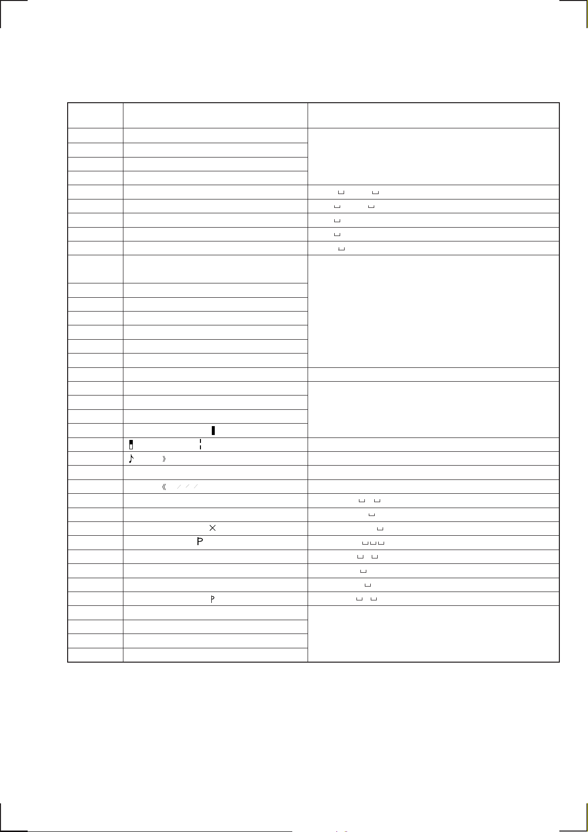
Table 2: CD-TEXT TEST DISC Recorded Data Contents and Display (TRACKS NO. 33 to 99)
(In this unit, some special characters cannot be displayed. This is no a fault.)
TRACK Recorded contents Display
33
34
35
36
37
38
39
40
41
42
43
44
45
46
47
48
49
50
51
52
53
54
55
56
57
58
59
60
61
62
63
64
65
66
67
to
99
100Hz/0dB/R*
1kHz/0dB/R*
10kHz/0dB/R*
20kHz/0dB/R*
100H square wave //L&R
1Hz square wave //L&R
1kHz emphasis ON/–0.37dB/L&R
5kHz emphasis ON/–4.53dB/L&R
16kHz emphasis ON/–9.04dB/L&R
! ” # $ % & ’ (21h to 27h)
1kHz 0dB L&R
()* + , – . / (28h to 2Fh)
0 1 2 3 4 5 6 7 (30h to 37h)
89:;<=>?(38h to 3Fh)
@A B C D E F G (40h to 47h)
H I J K L M N O (48h to 4Fh)
P Q R S T U V W (50h to 57h)
X Y Z [ ¥ ] ^ _ (58h to 5Fh)
‘ a b c d e f g (60h to 67h)
h i j k l m n o (68h to 6Fh)
p q r s t u v w (70h to 77h)
xyz{ I } ~ (78h to 7Fh)
i¢£¤¥ § (A0h to A7h) 8859-1
C ª ¬ PR – (A8h to AFh)
23
•±
†1º
‘ µ ¶ • (B0h to B7h)
341
1
4
¿ (B8h to BFh)
2
À Á Â Ã Ä Å Æ Ç (C0h to C7h)
È É Ê Ë Ì Í Î Ï (C8h to CFh)
DСТУФХЦ (D0h to D7h)
ШЩЪЫЬY ß (D8h to DFh)
à á â ã ä å æ ç (E0h to E7h)
è é ê ë ì í î ï (E8h to EFh)
∂ стуфхц÷ (F0h to F7h)
шщъыьy я (F8h to FFh)
No.66
No.67
to
No. 99
Same as the values shown in the left column.
100Hz Square Wave // L&R
1kHz Square Wave // L&R
1kHz w/emphasis /– 0.37dB/L&R
5kHz w/emphasis / – 4.53dB/L&R
16kHz w/emphasis / – 9.04dB/L&R
Same as the values shown in the left column.
X Y Z [ \ ] ^ _ (58h to 5Fh)
Same as the values shown in the left column.
(A0h to A7h) 8859-1
(A8h to AFh)
(B0h to B7h)
(B8h to BFh)
A A A A A A C (C0h to C7h)
E E E E I I I I (C8h to CFh)
D N O O O O O (D0h to D7h)
0 U U U U Y (D8h to DFh)
a a a a a a c (E0h to E7h)
e e e e i i i i (E8h to EFh)
d n o o o o o (F0h to F7h)
o u u u u y y (F8h to FFh)
Same as the values shown in the left column.
* Other channel is infinity zero.
— 9 —

IOP DATA RECORDING AND DISPLAY WHEN THE OPTICAL PICKUP AND NON-VOLATILE MEMORY
(BD (MD) BOARD IC171) IS REPLACED
The IOP value that is indicated on the optical pickup unit can be sav ed in the non-volatile memory . By saving the IOP v alue sav ed in the nonvolatile memory, it is no more necessary to read the IOP value on the optical pickup unit. It is recommended to save the IOP value saved in
the non-volatile memory when the optical pickup unit and/or non-volatile memory (BD (MD) board IC171) is replace as the followings.
How to save the IOP value in the non-volatile memory:
1. Turn on the power and select the MD function. Press the three buttons simultaneously, i.e., the ENTER/YES , NAME EDIT , and
MD3 buttons to activate the test mode.
2. Turn the MULTI JOG dial to show the message “[service]” on display. Press the ENTER/YES button.
3. Turn the MULTI JOG dial to show “Iop Write” (28) on display. Press the ENTER/YES button.
4. “REF=@@@.@” (@ is an arbitrary number) appears, and the number that can be changed as described in the next step, flashes.
5. Input the IOP value that is indicated on the optical pickup, as follows.
Selection of numeral : Select a number by turning the MULTI JOG dial.
Selection of digit : Select the desired digit by pressing the MD WALKMAN SYNC button.
6. Press the ENTER/YES button and the message “Measu=@@@.@” appears. (@ is an arbitrary number.)
7. Press the ENTER/YES button without changing the number because the result data of adjustment is saved as the value of step 6.
8. The message “Complete!!” appears for a moment. This value is saved in the non-volatile memory, and the message “Iop Write” is
displayed.
9. After saving is complete, press the REPEAT button to return to the normal operating mode.
How to display the IOP value saved in the non-volatile memory:
1. Turn on the power and select the MD function. Press the three buttons simultaneously, i.e., the ENTER/YES , NAME EDIT , and
MD3 buttons to activate the test mode.
2. Turn the MULTI JOG dial to show “[Service]” on display. Press the ENTER/YES button.
3. Turn the MULTI JOG to show “Iop Read” (C27) on display.
4. “@@.@/##.#” appears, and the saved contents are displayed.
@@.@ : The Iop value that is indicated on the pickup
##.# : The Iop value after adjustment is complete
5. T o exit this mode, press the MENU/NO b utton to show “Iop Read” on display. Press then the REPEA T button to return to the normal
operating mode.
— 10 —

CHECK BEFORE STARTING PARTS REPLACEMENT AND ADJUSTMENT
Cause of defect can be approximately located by performing the following checks before starting repair work. For the detailed procedure,
refer to “SECTION 6 ELECTRICAL ADJUSTMENTS”.
Laser power check
(page 44)
Traverse check
(page 45)
Focus bias check
(page 46)
CPLAY check
(page 46)
Self-record/playback check
(REC/PLAY)
(page 46)
TEMP check
(temperature compensation
offset adjustment)
(page 44)
Criterion of judgement
(If the value does not satisfy the following
specification value, it is judged as defective.)
• 0.9 mW power
Specification value: 0.84 to 0.92 mW
• 7.0 mW power
Specification value: 6.8 to 7.2 mW
• Iop (when 7 mW)
The Iop value that is indicated on the
optical pickup unit ±10 mA
• Traverse waveform
Specification value: Offset 10 % or less
• Error rate check
Specification value: At all points of a, b, c
C1 error 220 or less
AD error 2 or less
• Error rate check
Specification value:
a. When the test disc (MDW-74/AU-1) is
used
C1 error 80 or less
AD error 2 or less
b. When the check disc (TDYS-1) is used
C1 error 50 or less
• Error rate check with CPLAY
Specification value:
C1 error 80 or less
AD error 2 or less
• NG when “T=@@(##)[NG” is displayed
(@@ and ## are arbitrary numbers.)
Countermeasure when result of judgement
is defective
• Cleaning the optical pickup
• Re-adjustment
• Replacement of the optical pickup
• Replacement of the optical pickup
• Replacement of the optical pickup
• Replacement of the optical pickup
• Replacement of the optical pickup
When test result is all the time defective:
• Replacement of the over-write head
• Check that circuits in the peripheral of the
over-write head are not open
When test result is defective from time to
time:
• Check if the over-write head is not deformed
• Mechanical check on parts around the sledding
mechanism
• Check that circuits in the peripheral of D101
(BD board) are not open
• Check signals in the peripheral of IC101, 121,
CN102, 103 (BD board)
Note: The criterion of judgement is presented only for the purpose of judgment whether specifications are satisfied or not. This is not the
specification values of adjustments.
When any adjustments are attempted, use the specification values that are described in the respective adjustment procedures.
— 11 —
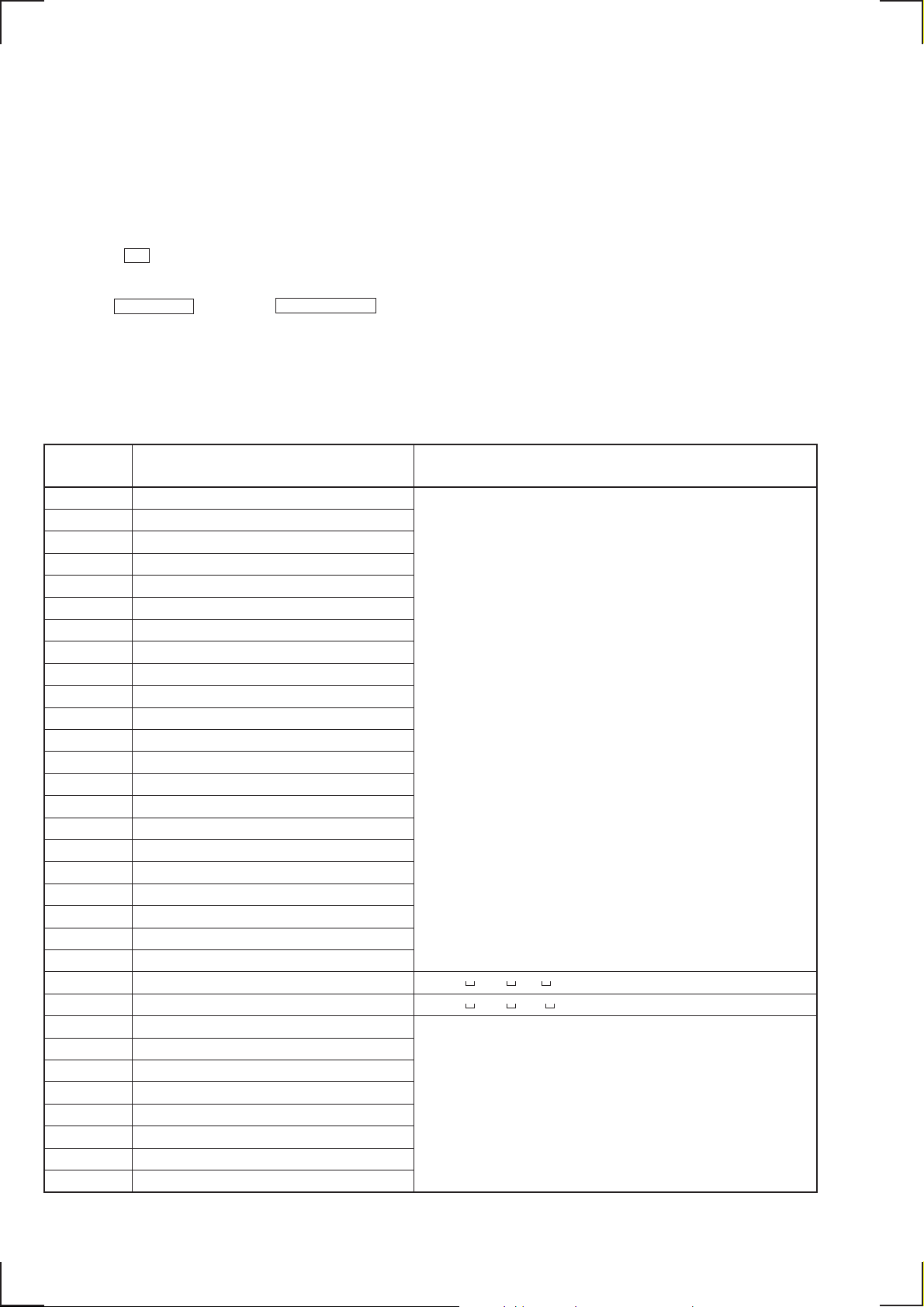
SECTION 3
GENERAL
#¡
#º
@ª
@•
@¶
@§
@∞
@¢
@£
@™
@¡
@º
1
2
3
4
5
6
7
8
9
!º
!¡
!™
!£
!¢
!∞
!§
!¶!•!ª
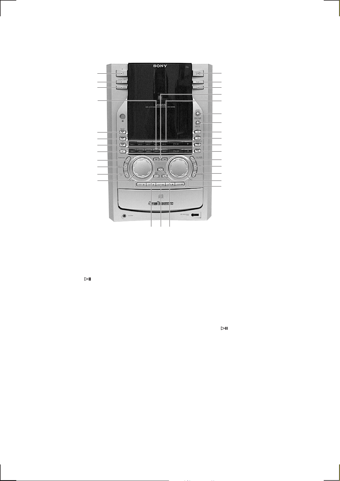
1 TUNER/BAND button
2 DBFB button
3 MD6 button
4 CURSOR 0/) buttons
5 MD1 – MD5/
/p buttons
6 SPECTRUM ANALYZER UPPER DISPLAY
button
7 SPECTRUM ANALYZER LOWER DISPLA Y
button
8 REC button
9 REC MODE button
!º MD WALKMAN SYNC button
!¡ GROOVE button
!™ PLAY MODE TUNNING MODE button
!£ 1/ALL button
!¢ REPEAT STEREO/MONO button
!∞ VOLUME dial
!§ CLEAR button
!¶ ENTER/YES button
!• CD1 6 – CD5 6 buttons
!ª MENU/NO button
@º MULTI JOG dial
@¡ PRESET EQ button
@™ NAME EDIT/CHARACTER button
@£ FUNCTION button
@¢ REC IT button
@∞ HIT PARADE button
@§ SEAMLESS button
@¶ SELECT SYNC button
@• CD1 – CD5/ /p buttons
@ª TIMER SELECT button
#º SET button
#¡ 1/u (power) button
— 12 —
This section is extracted
from instruction manual.
— 13 —
— 14 —
— 15 —
— 16 —
— 17 —
— 18 —
— 19 —
— 20 —
— 21 —
— 22 —
— 23 —
— 24 —
SECTION 4
s
DISASSEMBLY
Note : Follow the disassembly procedure in the numerical order given.
4-1. BACK PANEL
• Remove the upper cover first.
5
Three connectors
6
Back panel
3
T en screws
(+BV 3 × 8)
2
Cover (Back)
4-2. MECHANISM (MDM-C1E)
6
MD mechanism
(MDM-C1E)
5
Three screws
(+BV 3 × 8)
4
Seven screws
(+BV 3 × 8)
4
Cover (MDM)
1
TUNER
1
Three screw
(+BV 3 × 8)
3
Screw (+BV 3 × 8)
2
Screw (+BV 3 × 8)
— 25 —
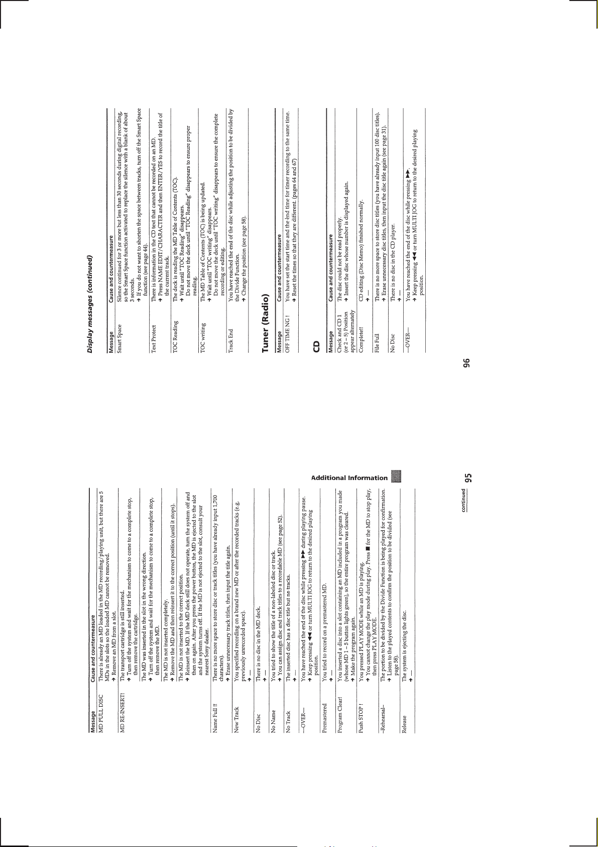
4-3. SP BOARD, AMP BOARD, REG BOARD, TRANS-D BOARD (JE, HK, SP, MY MODEL)
)
d
Abbreviation
HK : Hong Kong
SP : Singapore
MY : Malaysia
JE : Tourist
8
AMP board
1
Two connectors
7
Two screws
×
(+BV 3
16)
3
SP board
5
Connector
2
Two screws
(+BV 3
9
!º
Heat sink
×
8)
!¡
Screw (+BV 3 × 16)
!£
Two screws
(+BV 3
(JE, HK, SP, MY MODEL
Back panel
Four screws
(+BV 3
!™
REG board
×
8)
×
12)
4
Two connectors
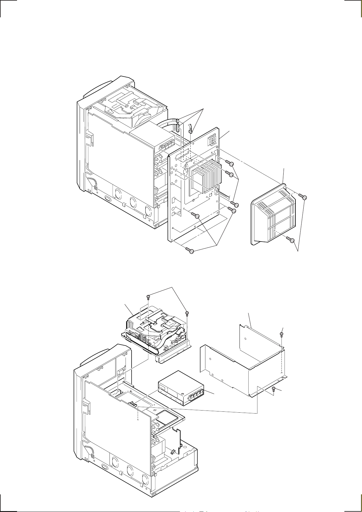
4-4. FRONT PANEL
!£
Front panel
6
Screw (+BV 3 × 8)
8
Flat type wire
(29 core)
!º
!¢
TRANS-D board
(JE, HK, SP, MY MODEL)
7
Connector
1
Two connectors
5
Holder (WLS-10)
(Remove the holder from
the MAIN board. )
9
MAIN boar
2
Flat type wire
(19 core)
!™
6
!¡
Three screws
(+BV 3
— 26 —
Connector
3
(17 core)
×
8)
Flat type wire
4
Two screws
(+BV 3
×
8)
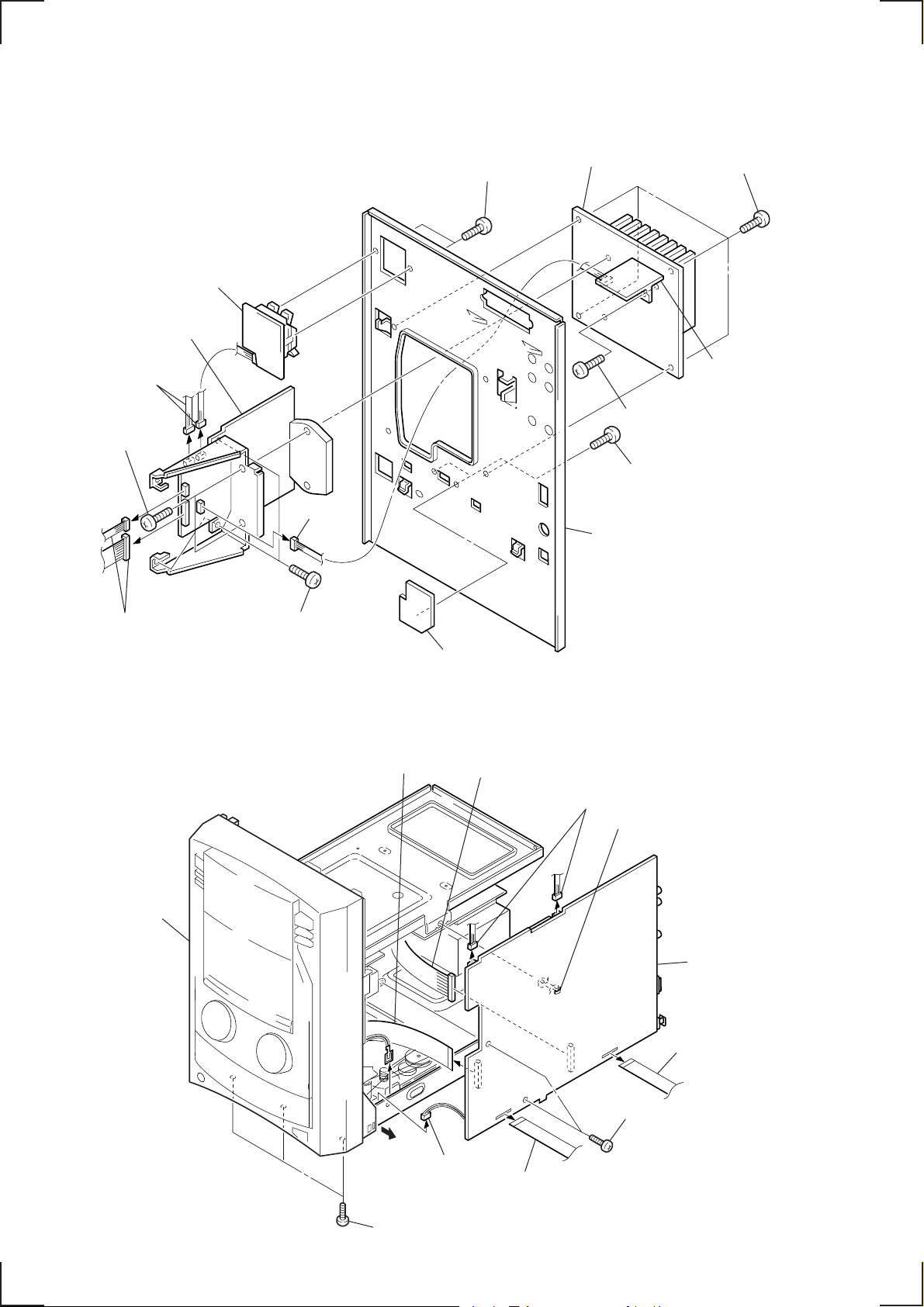
4-5. POWER KEY BOARD, LED BOARD, PANEL BOARD
)
6
POWER KEY board
8
LED board
5
Two screws
9
Two screws
(+BVTP 2.6
!™
PANEL board
Front panel
×
8)
(+BVTP 2.6
7
Screw
(+BVTP
2.6
!º
screws
(+BVTP
2.6
!¡
Three screws
(+BVTP 2.6
Four
×
8)
×
8)
×
8)
×
8)
1
Two screws
(+BV 3
3
Two screws
(+BVTP 2.6
×
8)
2
4
Bracket
(MD chassis)
×
8)
Chassis (MD)
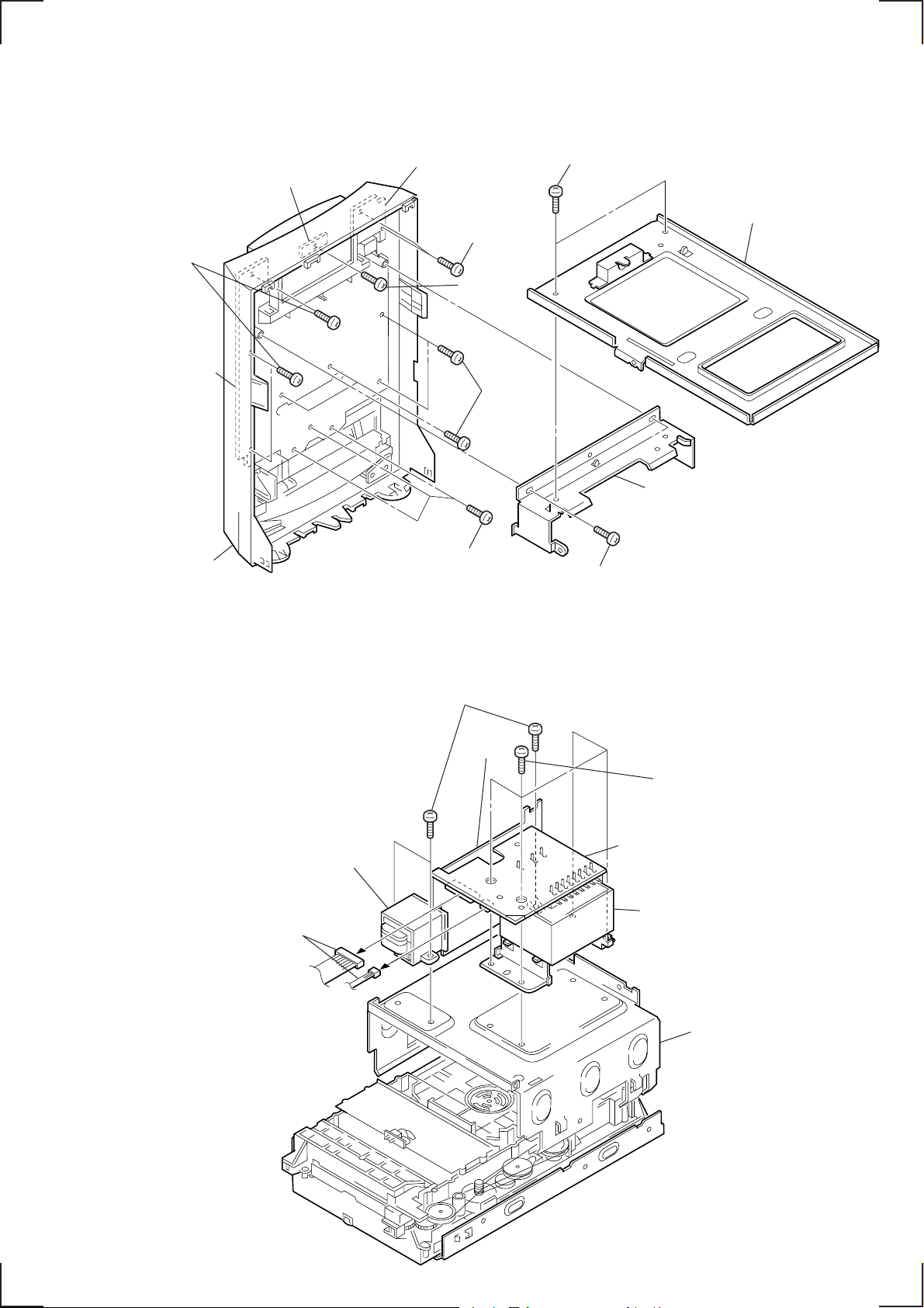
4-6. POWER TRANSFORMER (T960), TRANS-A/B/C BOARD
2
Three screws
7
TRANS-C board
4
Two connectors
(+BV 3
×
10)
5
TRANS-A
board
6
1
Four screws
(+BVTT 3
TRANS-B board
3
Power transformer
(T960)
8
Chassis (Transformer
×
8)
— 27 —
4-7. CD MECHANISM (CDM53-K1BD33)
2
Two screws
(+BV 3 × 8)
3
CD mechanism
(CDM53-K1BD33)
1
Two screws
(+BV 3 × 8)
Chassis
— 28 —
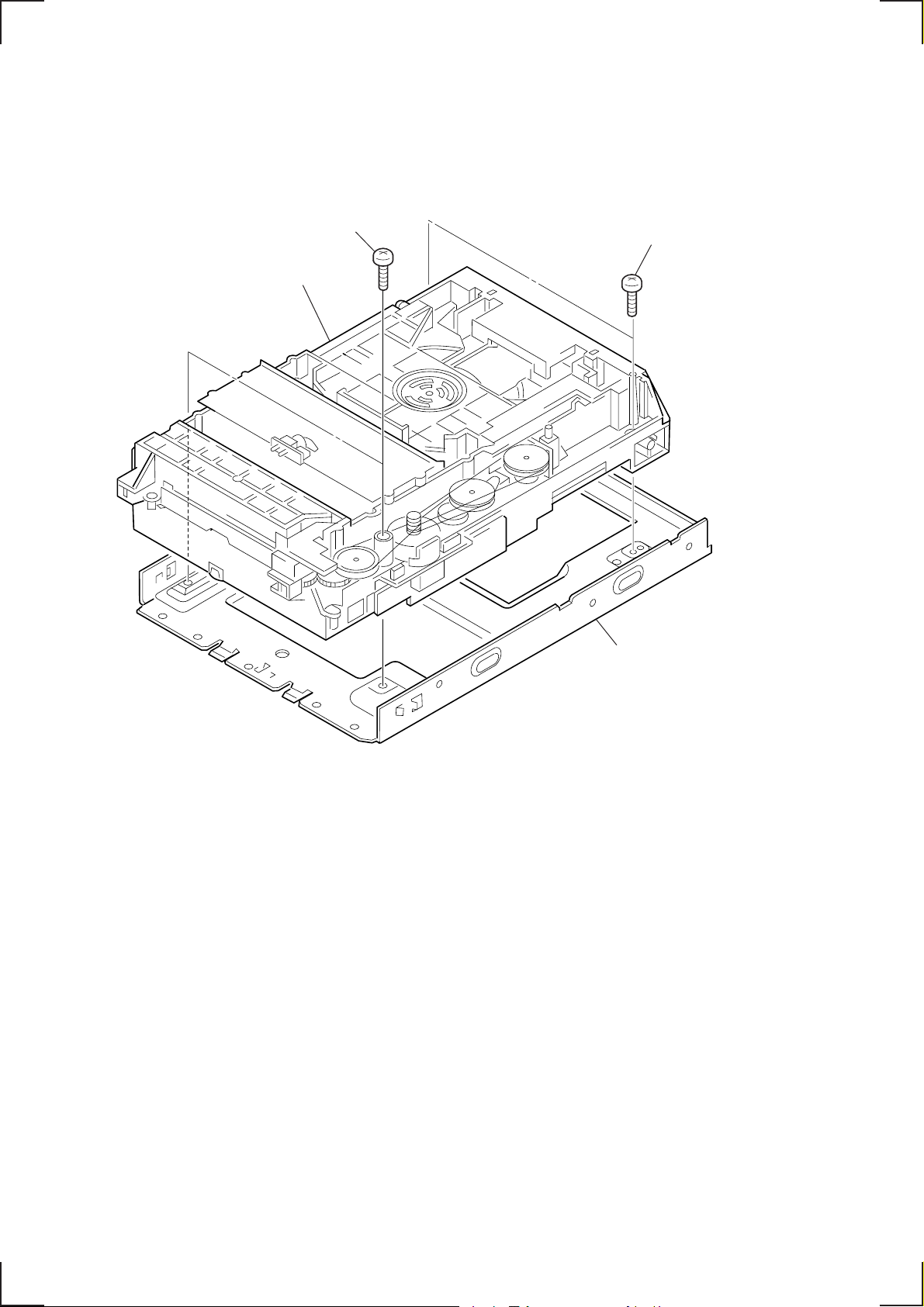
4-8. ESCUTCHEON, CHASSIS (TOP)
)
6
Cover (FFC)
4
Flat type wire
(13 core)
3
Flat type wire
(7 core)
5
Two screws
(+BVTT 2.6 × 5)
7
!¡
Screw (+BVTT 2.6 × 5)
9
Bracket (To assemble the bracket,
refer to the following note.)
!º
T wo screws
(+P 2 × 5)
!™
Chassis (TOP)
8
Lever (S) assy
Note: When assembling the bracket, raise the lever (S) assembly,
engage it with the bracket, and slide them in the direction
of the arrow.
Lever (S) assy
2
Escutcheon
Screw (+BVTT 2.6 × 5)
Bracket
1
Four screws
(+BVTT 2.6 × 5
— 29 —
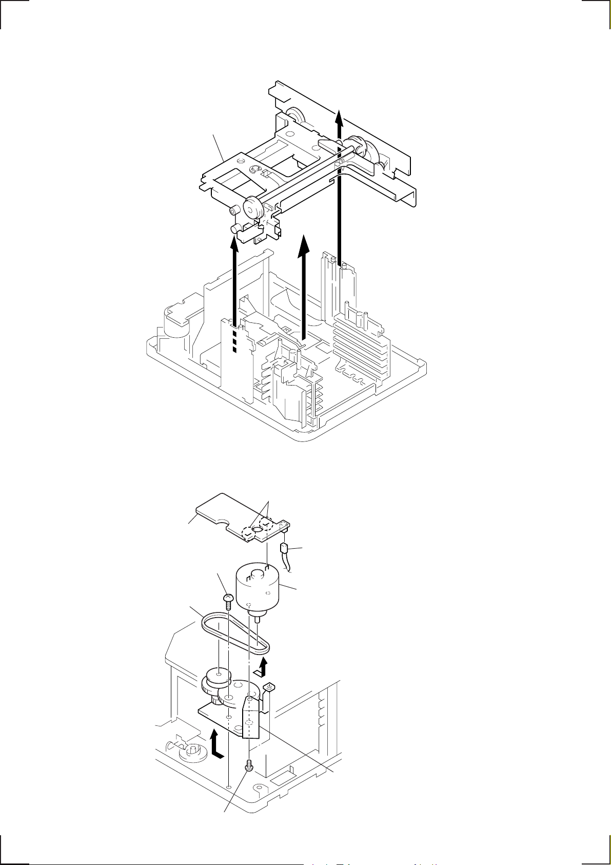
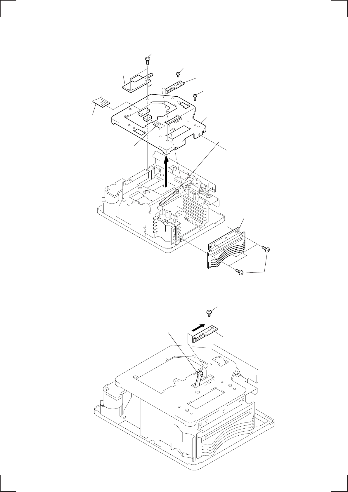
4-9. CHASSIS (ELEVATOR) NEW
e
1
Chassis (Elevator) NEW assy
4-10. MOTOR (HEAD) ASSY (M905), HEAD RELAY BOARD
7
Remove soldering of the motor.
8
HEAD RELAY board
Screw
3
(+BVTT 2.6
2
Belt A
×
5)
6
Remove the motor assy in the
direction of the arrow
B
A
1
Connector
Motor (Head) assy (M905)
B
.
5
Two screws
(+P 2
4
Chassis (Head gear) assy
Remove the chassis assy in th
direction of the arrow A.
×
2)
— 30 —
 Loading...