

Sony HCD-MD515 - Component For Dhcmd515 Service Manual

MINI Hi-Fi COMPONENT SYSTEM
MICROFILM
US Model
AEP Model
UK Model
E Model
Tourist Model
Model Name Using Similar Mechanism NEW
CD Mechanism Type CDM48-5BD29
Base Unit Name BU-5BD29
Optical Pick-up Name KSS-213BA/F-NP
Model Name Using Similar Mechanism NEW
MD Mechanism Type MDM-C1D
Base Unit Name MBU-C1
Optical Pick-up Name KMS-260A/J1N
SPECIFICATIONS
SERVICE MANUAL
HCD-MD515
RM-MD515
HCD-MD515 is the Amplifier, CD player, MD
Deck and Tuner section and RM-MD515 is the
Detachable Controller section in DHC-MD515.
U.S and foreign patents licensed from Dolby Laboratories Licensing Corporation.
CD
Section
MD
Section
RM-MD515
HCD-MD515
– 2 –
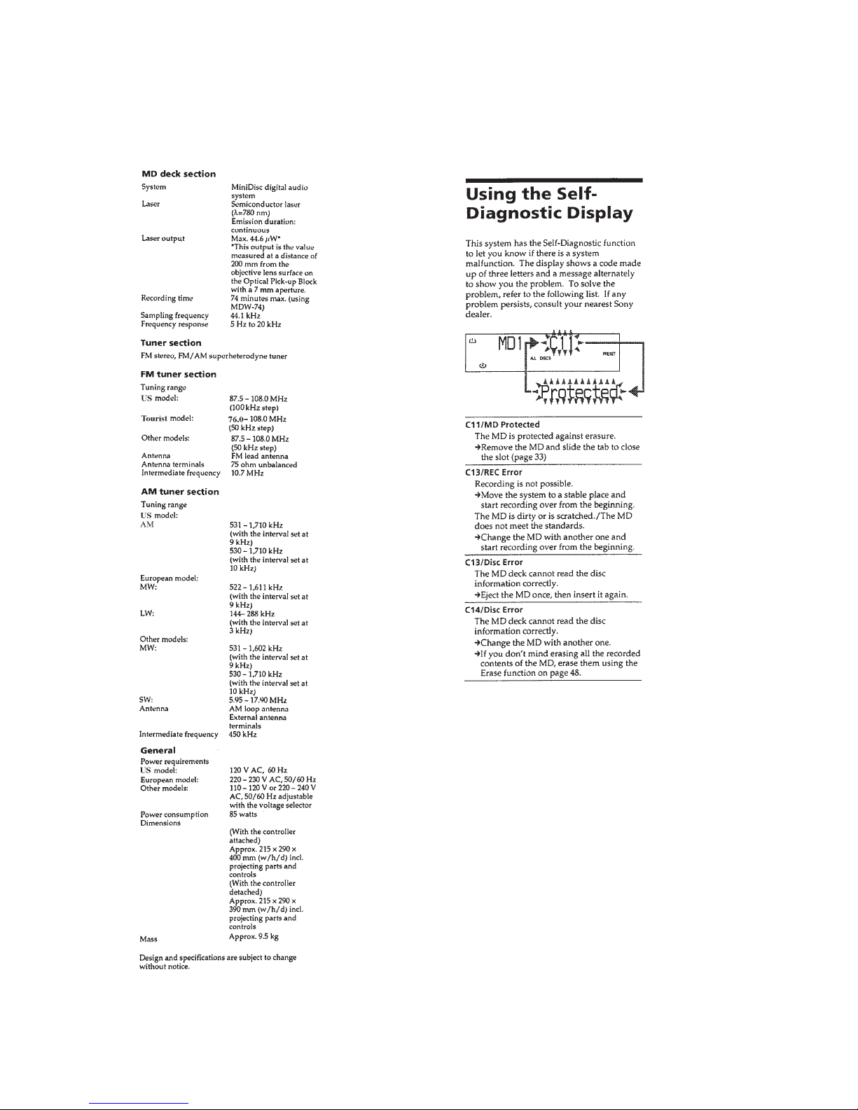
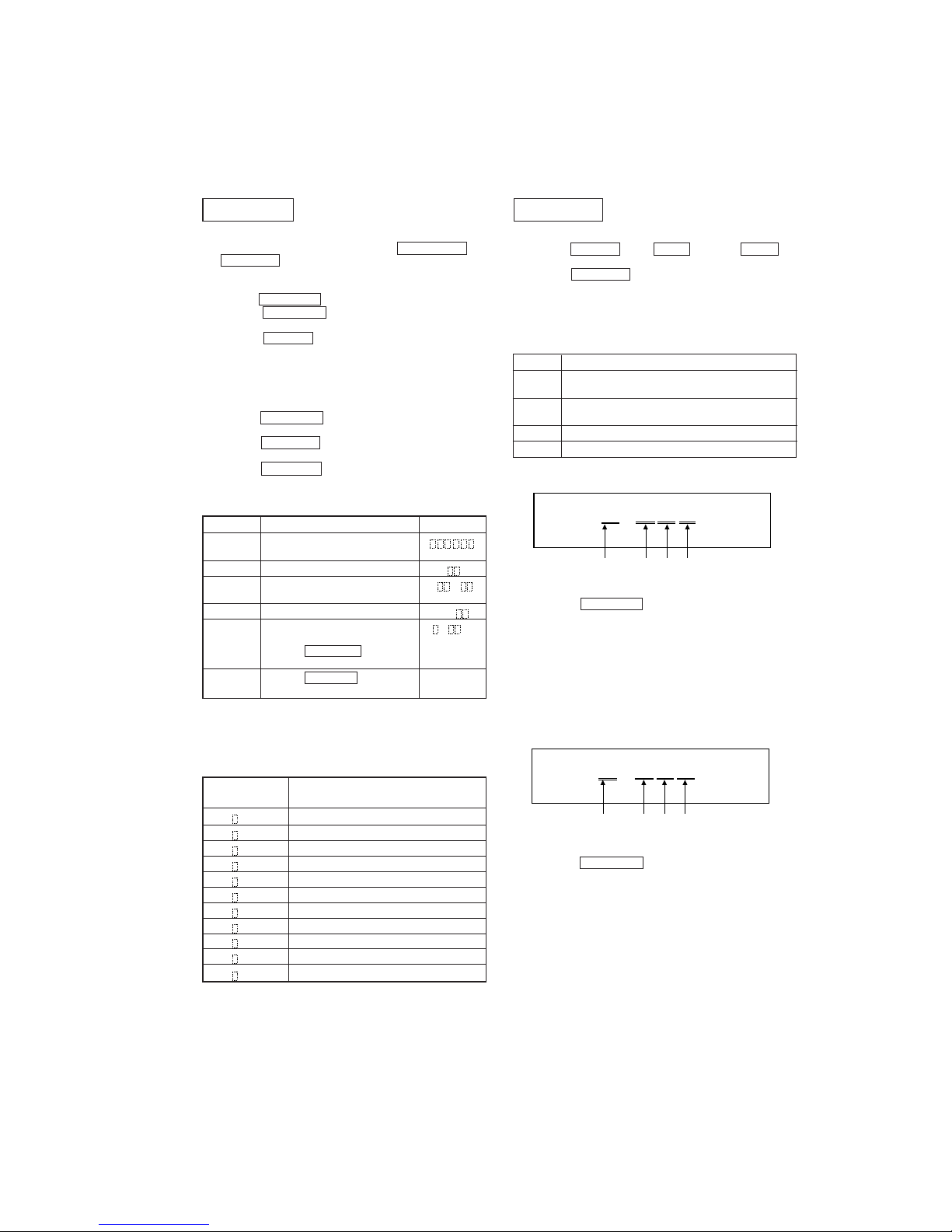
SELF DIAGNOSTICS
– 3 –
CD SECTION
1. OPERATING THE DISPLAYED HISTORYS
1. Press the DIMMER button, DBFB button, and CD 16 button simultaneously and enter the test mode.
2. Press the PROGRAM button, and mechanical error count and
the cout of “NO DISC” that optical system judged are displyed.
3. Under this condition press the buttons in Table 2, and the respective operations are executed as listed below.
Table 2.
Button Function
MD/CD 1 Mechanical error cord from latest one to last ten are dis-
played each time this button is pressed. (*1)
MD/CD 2 The reasons of “NO DISC” from latest one to last ten are
displayed each time this button is pressed. (*2)
CD 16 Reset the count of mechanical error.
CD 26 Reset the count of “NO DISC”.
(*1) Mechanical error code
MD SECTION
1. OPERATING THE ERROR HISTORY MODE
All operations are performed using the MULTI JOG dial
and PROGRAM button.
1. Enter the test mode for MD function. (*1)
2. Turn the MULTI JOG dial and display “ERR DP MODE”.
3. Press the ENTER/YES button, therefor enter the error history mode and change the display “total rec”.
4. Press the EDIT/NO button, therefor end the error history
mode and change the display “ERR DP MODE”.
(*1) See the “SECTION 4 TEST MODE” (page 21) for
detail of test mode.
Table 1.
Contents Function Display
total rec Total time of laser power high. r h
About 20% of total recording time.
total play Total time of playback. p h
retry error Total count of record and playback r p
retry error.
total error Total count of error. total
err history Error contents display of from 0 E (*2)
latest one“00” to last ten “09”.
(Turn the MULTI JOG dial and
change the error NO.)
err refresh Press the PROGRAM button and complete
(*3) clear the error histories memory
2. OPERATING THE DISPLAYED HISTORYS
1. Turn the MULTI JOG dial and change the display of error
history contents.
2. Press the PROGRAM button and display error history function.
3. Press the PROGRAM button again and back the display of
error history contents.
(*2) See table 1-1. for contents of each error code.
(*3) Error refresh with optical pick-up exchange, another not ex-
ecute.
Table 1-1.
Display
Contents
(error No./code)
0: E00 No error
0: E01 Disc error PTOC does not read
0: E02 Disc error UTOC does not read
0: E03 Loading error
0: E04 Address does not read
0: E05 Out of FOK
0: E06 Focus does not work
0: E07 Retry of record
0: E08 Record retry error
0: E09 Retry of Playback
0: E0A Playback retry error
(a) The number of Mechanical error.
Latest one “00” to last ten “09”
(Turn the MULTI JOG dial and change the error No.)
(b) “FF”: Mechanical error, when mechanical initialize to
completion.
Others: Mechanical error in the midst of mechanical initialize.
(c) “4
*
”: Mechanical error in the midst of mechanical initial-
ize, when sub tray set into the stocker.
“5
*
”: Mechanical error in the midst of mechanical initial-
ize, when sub tray take out to the stocker.
(d) “2
*
”: Mechanical error in the midst of elevator moving.
(*2) NO DISC error code
(a) The number of NO DISC error.
Latest one “00” to last ten “09”
(Turn the MULTI JOG dial and change the error No.)
(b) “01”: Focus error
“02”: GFS error
“03”: Set up error
(c) “00”: NO DISC error (Does not chucking retry)
“02”: NO DISC error (Chucking retry to completion)
(d) The status, when judged NO DISC error.
“3
*
”: Stop
“4*”: Set up
“5
*
”: TOC read
“6*”: Access
“7
*
”: Play
“8*”: Pause
“9
*
”: Manual search (Play)
M0 =
(a) (b) (c) (d)
* ******
D0 =
(a) (b) (c) (d)
* ******

– 4 –
TABLE OF CONTENTS
SELF DIAGNOSTICS ...................................................... 2
1. SERVICING NOTES............................................... 4
2. GENERAL ................................................................... 6
3. DISASSEMBLY ......................................................... 8
4. TEST MODE.............................................................. 21
5. ELECTRICAL ADJUSTMENTS
MD Section ..................................................................... 24
CD Section ...................................................................... 29
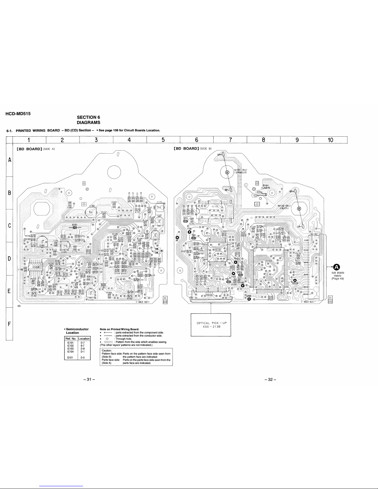
6. DIAGRAMS
6-1. Printed Wiring Board – BD (CD) Section –.................. 31
6-2. Schematic Diagram – BD (CD) Section –...................... 33
6-3. Printed Wiring Boards – BD (MD) Section – ............... 36
6-4. Schematic Diagram – BD (MD) Section –.................... 39
6-5. Schematic Diagram – SUB Section –............................. 44
6-6. Printed Wiring Board – SUB Section –.........................49
6-7. Printed Wiring Boards – MAIN Section – .................... 52
6-8. Schematic Diagram – MAIN Section –.......................... 55
6-9. Schematic Diagram –PANEL Section –......................... 60
6-10. Printed Wiring Boards – PANEL Section – .................. 65
6-11. Printed Wiring Boards
– CD (Motor/ Sensor) Section – .................................... 67
6-12. Schematic Diagram
– CD (Motor/ Sensor) Section – ..................................... 69
6-13. Printed Wiring Boards
– MD (Motor/ Sensor) Section – .................................... 71
6-14. Schematic Diagram
– MD (Motor/ Sensor) Section – .................................... 73
6-15. Printed Wiring Boards
– POWER/AMPLIFIER Section – ................................. 75
6-16. Schematic Diagram
– POWER/AMPLIFIER Section – ................................. 77
6-17. Printed Wiring Boards
– DETACHABLE CONTROLLER Section
(RM-MD515) – .............................................................. 79
6-18. Schematic Diagram
– DETACHABLE CONTROLLER Section
(RM-MD515) – ............................................................... 81
6-19. IC Pin Function Description ........................................... 92
7. EXPLODED VIEWS...............................................107
8. ELECTRICAL PARTS LIST .............................. 117
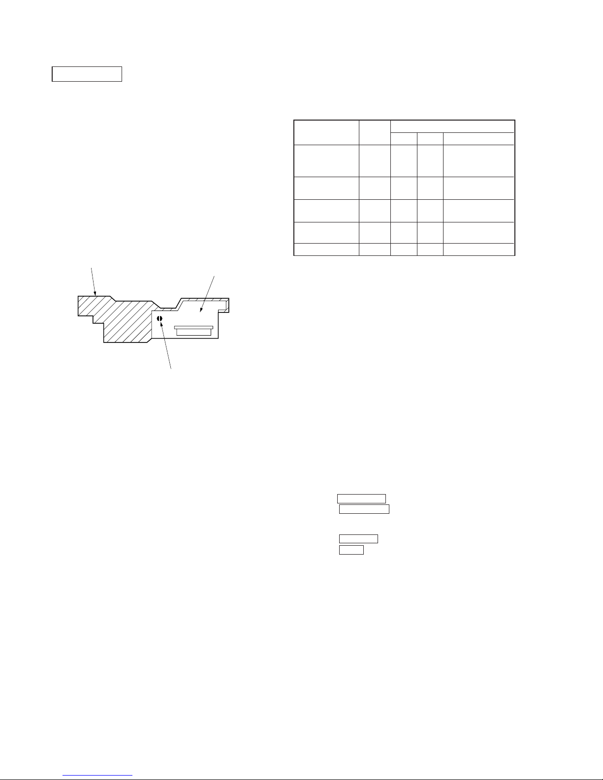
NOTES ON HANDLING THE OPTICAL PICK-UP
BLOCK OR BASE UNIT
The laser diode in the optical pick-up block may suffer electrostatic break-down because of the potential difference generated
by the charged electrostatic load, etc. on clothing and the human
body.
During repair, pay attention to electrostatic break-down and also
use the procedure in the printed matter which is included in the
repair parts.
The flexible board is easily damaged and should be handled with
care.
NOTES ON LASER DIODE EMISSION CHECK
The laser beam on this model is concentrated so as to be focused
on the disc reflective surface by the objective lens in the optical
pick-up block. Therefore, when checking the laser diode emission, observe from more than 30 cm away from the objective lens.
Notes on chip component replacement
• Never reuse a disconnected chip component.
• Notice that the minus side of a tantalum capacitor may be damaged by heat.
Flexible Circuit Board Repairing
• Keep the temperature of the soldering iron around 270 ˚C during repairing.
• Do not touch the soldering iron on the same conductor of the
circuit board (within 3 times).
• Be careful not to apply force on the conductor when soldering
or unsoldering
SAFETY-RELATED COMPONENT WARNING!!
COMPONENTS IDENTIFIED BY MARK ! OR DOTTED
LINE WITH MARK ! ON THE SCHEMATIC DIA GRAMS
AND IN THE PARTS LIST ARE CRITICAL TO SAFE
OPERATION. REPLACE THESE COMPONENTS WITH
SONY PARTS WHOSE PART NUMBERS APPEAR AS
SHOWN IN THIS MANU AL OR IN SUPPLEMENTS PUBLISHED BY SONY.
SECTION 1
SERVICING NOTES
– 5 –
CAUTION
Use of controls or adjustments or performance of
procedures other than those specified herein may
result in hazardous radiation exposure.
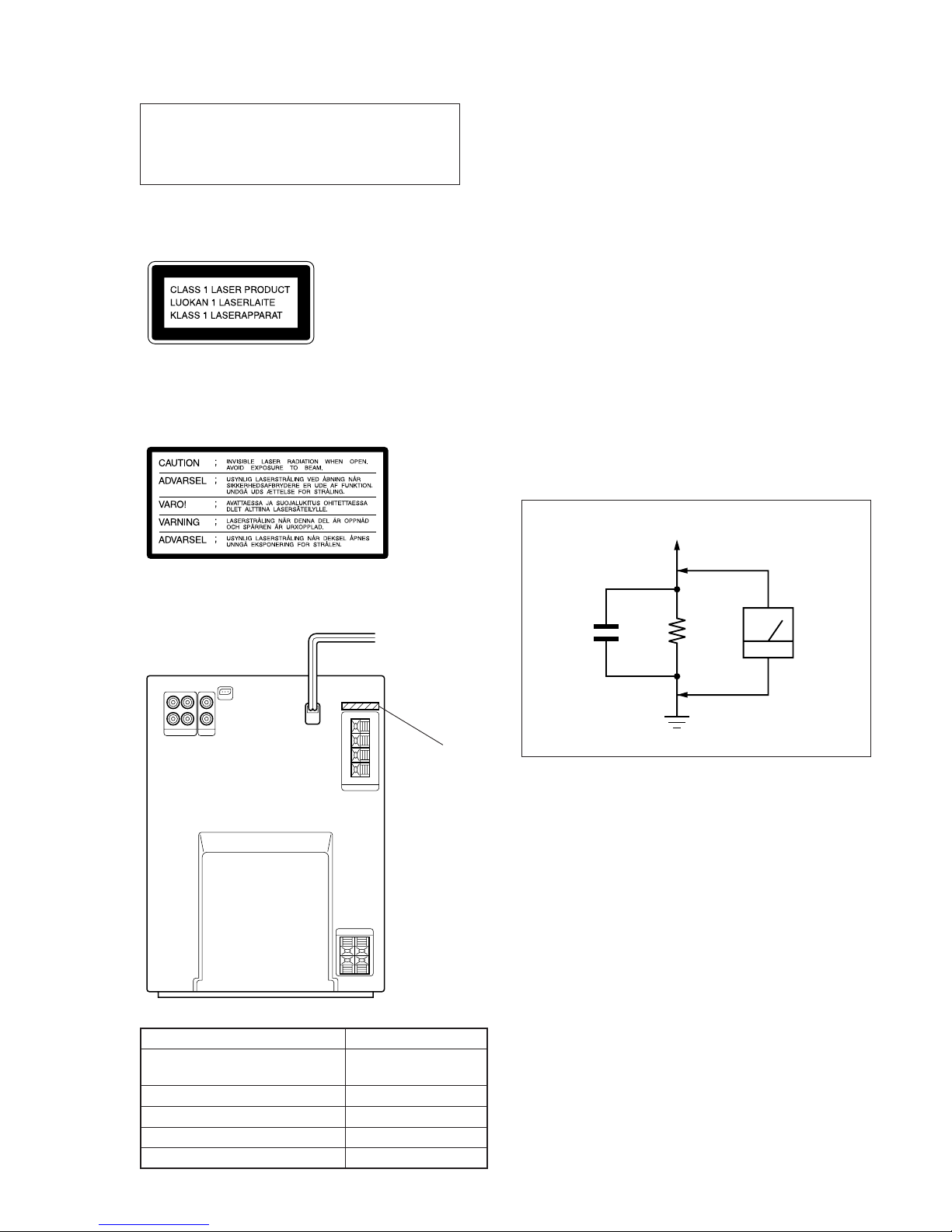
This appliance is classified as a CLASS 1 LASER product.
The CLASS 1 LASER PRODUCT MARKING is located on
the rear exterior.
Laser component in this product is capable of emitting radiation
exceeding the limit for Class 1.
The following caution label is located inside the unit.
MODEL IDENTIFICATION
– Back Panel –
MODEL PARTS No.
AEP, UK, German and
North European models
4-993-619-1π
Malaysia and Singapore models 4-993-619-2π
Hong Kong model 4-993-619-3π
US model 4-993-619-4π
Tourist model 4-993-619-6π
PART No.
SAFETY CHECK-OUT
After correcting the original service problem, perform the following safety check before releasing the set to the customer:
Check the antenna terminals, metal trim, “metallized” knobs,
screws, and all other exposed metal parts for AC leakage.
Check leakage as described below.
LEAKAGE TEST
The AC leakage from any exposed metal part to earth ground and
from all exposed metal parts to any exposed metal part having a
return to chassis, must not exceed 0.5 mA (500 microampers.).
Leakage current can be measured by any one of three methods.
1. A commercial leakage tester, such as the Simpson 229 or RCA
WT -540A. Follo w the manufacturers’ instructions to use these
instruments.
2. A battery-operated AC milliammeter. The Data Precision 245
digital multimeter is suitable for this job.
3. Measuring the voltage drop across a resistor by means of a
VOM or battery-operated AC voltmeter. The “limit” indication is 0.75 V, so analog meters must have an accurate lowvoltage scale. The Simpson 250 and Sanwa SH-63Trd are examples of a passive VOM that is suitable. Nearly all battery
operated digital multimeters that have a 2 V A C range are suitable. (See Fig. A)
Fig. A. Using an AC voltmeter to check AC leakage.
1.5 k
Ω
0.15 µF
AC
voltmeter
(0.75 V)
To Exposed Metal
Parts on Set
Earth Ground
– 6 –
SECTION 2
GENERAL
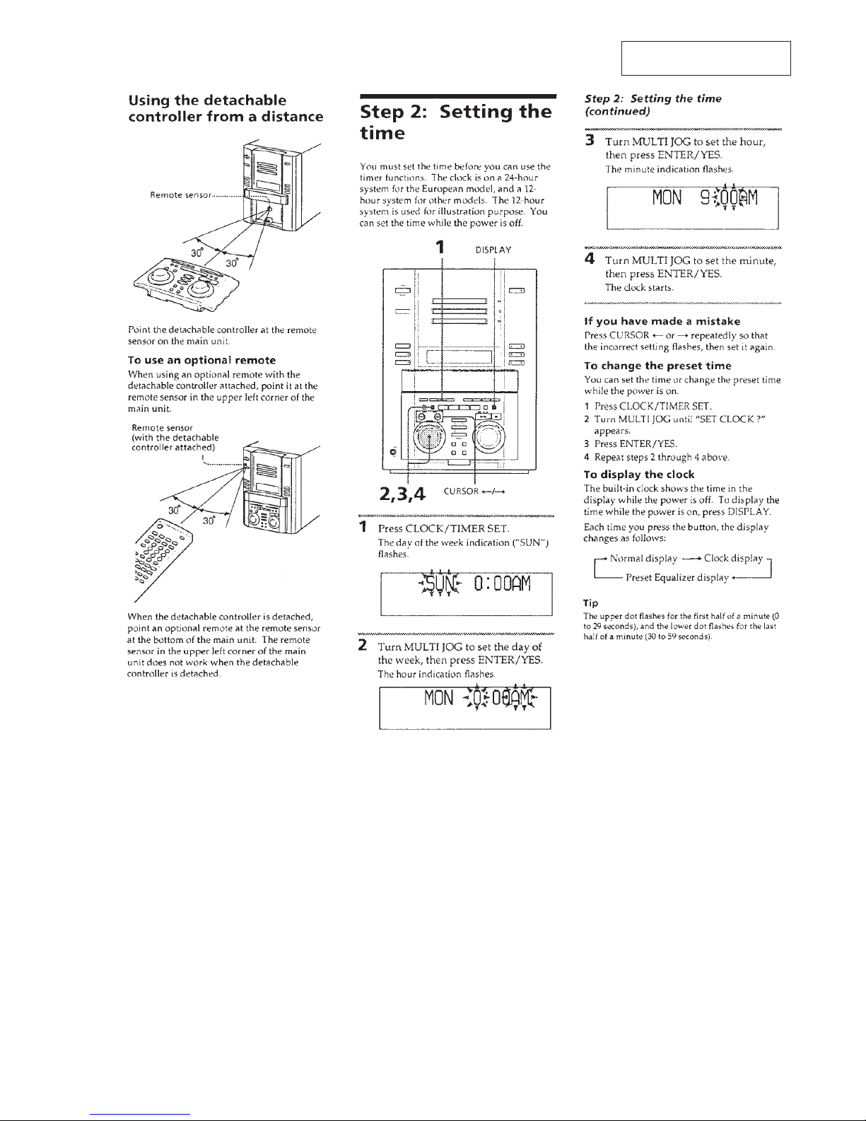
LOCATION OF CONTROLS
– Main Unit (HCD-MD515) –
1 GROOVE button and indicator
2 Fluorescent indicator tube
3 POWER button
4 Remote sensor (for optional remote controller)
5 MD slots
6 MD 1 to 3 indicator
7 MD 6 button
8 CD 1 to 3 6 (open/close) button and indicator
9 CD disc tray
!º PHONES jack
!¡ DIMMER button
!™ DBFB button and indicator
!£ Remote sensor (for detachable controller)
!¢ Detachable controller terminal
1 EDIT/NO button
2 ENTER/YES button
3 POWER button
4 PRESET EQ button
5 CLOCK/TIMER SET button
CLOCK/TIMER SELECT button
6 TAPE button
MD button
CD button
TUNER (BAND) button
7 MANUAL, CONTINUE button
AUTO, SHUFFLE button
PRESET, PROGRAM button
STEREO/MONO, REPEAT button
8 FUNCTION button
9 DISPLAY button
!º ^ button
!¡ p button
!™ VOLUME dial
!£ DISC SKIP button
!¢ REC/CD-MD SYNC button
!∞ REC IT button
!§ CD LOOP button
!¶ MD/CD 1 to 3 button
!• MULTI JOG dial
!ª 0 N button
) n button
– Detachable Controller (RM-MD515) –
– 7 –
This section is extracted from
instruction manual.

– 8 –
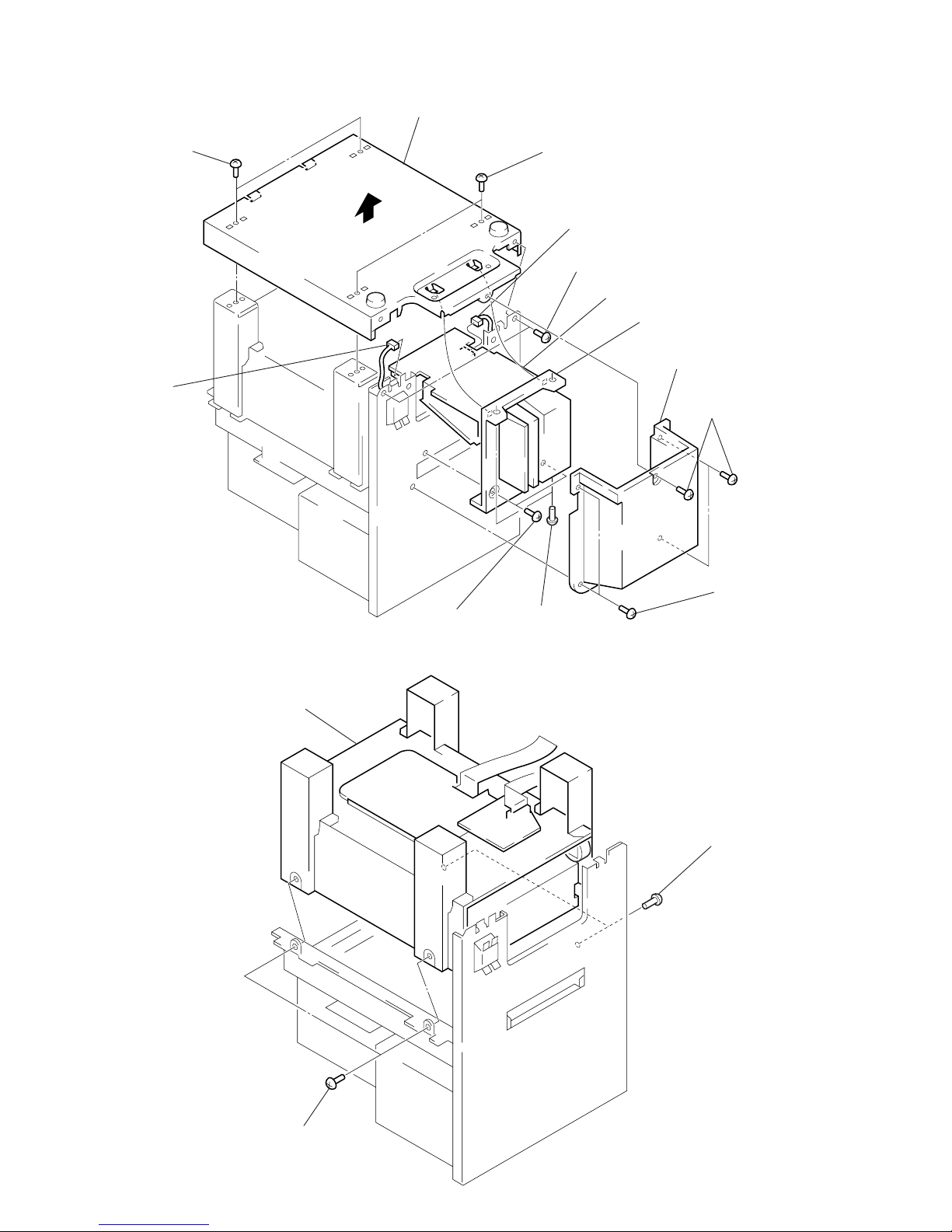
SECTION 3
DISASSEMBLY
• This set can be disassembled in the order shown below.
DETACHABLE CONTROLLER
(RM-MD515)
(Page 9)
CABINET (REAR) ASS’Y
(DETACHABLE CONTROLLER)
(Page 9)
MD MECHANISM DECK SECTION (MDM-C1D)
(Page 11)
OPTICAL PICK-UP (KMS-260A/J1N) (for MD)
(Page 15)
OPTICAL PICK-UP (KSS-213BA/F-NP) (for CD),
SLED MOTOR (M102)
(Page 19)
CASE
(Page10)
FRONT PANEL SECTION
(Page 10)
MAIN BOARD, SUB BOARD
(Page 11)
HOLDER (FN),
CHASSIS (TOP)
(Page 12)
CHASSIS (ELEVATOR)
(NEW) ASS’Y
(Page 13)
TRAY (SUB)
ASS’Y
(Page 17)
OPTICAL
PICK-UP CLEANING
(Page 18)
OVER WRITE HEAD (HR901)
(Page 15)
SPINDLE MOTOR (M101)
(Page 20)
MD BASE UNIT
(MBU-C1)
(Page 14)
MOTOR (HEAD)
ASS’Y (M905)
(Page 13)
BD (MD) BOARD
(Page 14)
STOCKER ASS’Y
(Page 17)
BD (CD) BOARD
(Page 19)
AMP BOARD
(Page 16)
CD MECHANISM DECK SECTION (CDM48-5BD29)
(Page 16)
CD BASE UNIT (BU-5BD29)
(Page 18)
– 9 –
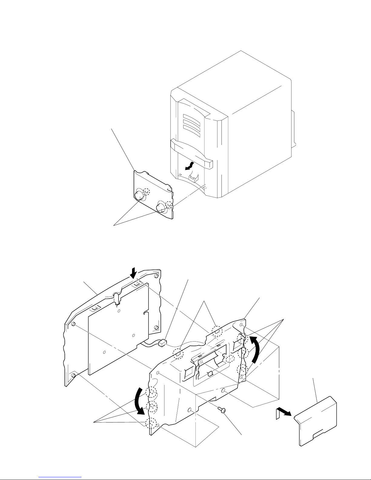
Note: Follow the disassembly procedure in the numerical order given.
DETACHABLE CONTROLLER (RM-MD515)
CABINET (REAR) ASS’Y (DETACHABLE CONTROLLER)
2
Detachable controller (RM-MD515)
to direction of the arrow.
1
two claws
3
Hold the arrow
B
of cabinet (front) ass’y.
B
4
Remove eighth claws as
turn the cabinet (rear) ass’y
to direction of the arrow C.
5
connector
(CN2)
two claws
1
Remove the battery
case lid to direction
of the arrow A.
2
seventh screws
(P2 × 4)
three claws
A
C
three claws
C
– 10 –
CASE
FRONT PANEL SECTION
1
connector
(CN200)
2
screw
(BV3 × 8)
2
two screws
(BV3 × 8)
3
Remove the case to
direction of the arrow.
1
four screws
(case 3TP2)
1
four screws
(case 3TP2)
1
flat wire (19 core)
(CN400)
2
earth lead
5
front panel section
4
two claws
3
three screws
(BV3 × 8)
4
claw
4
two claws
– 11 –
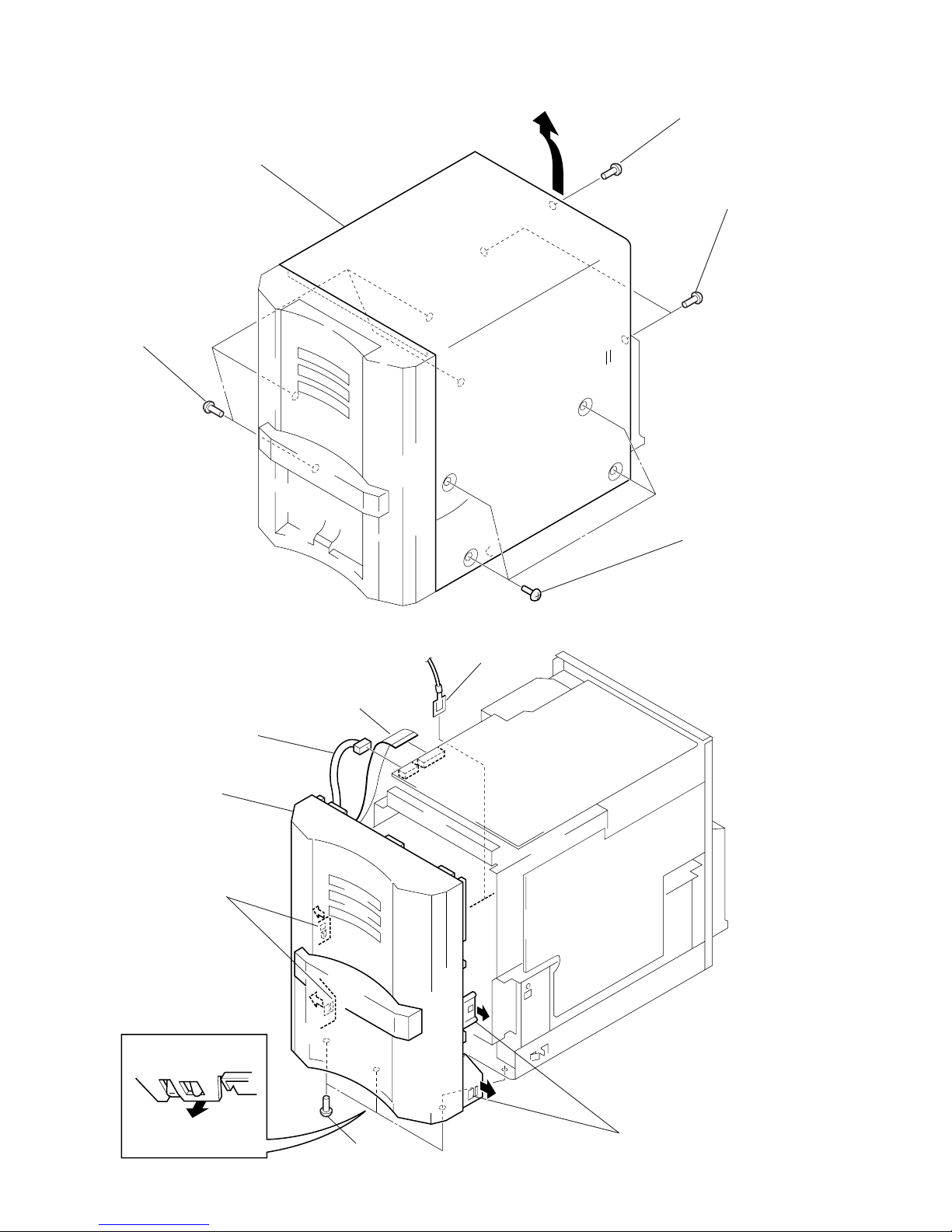
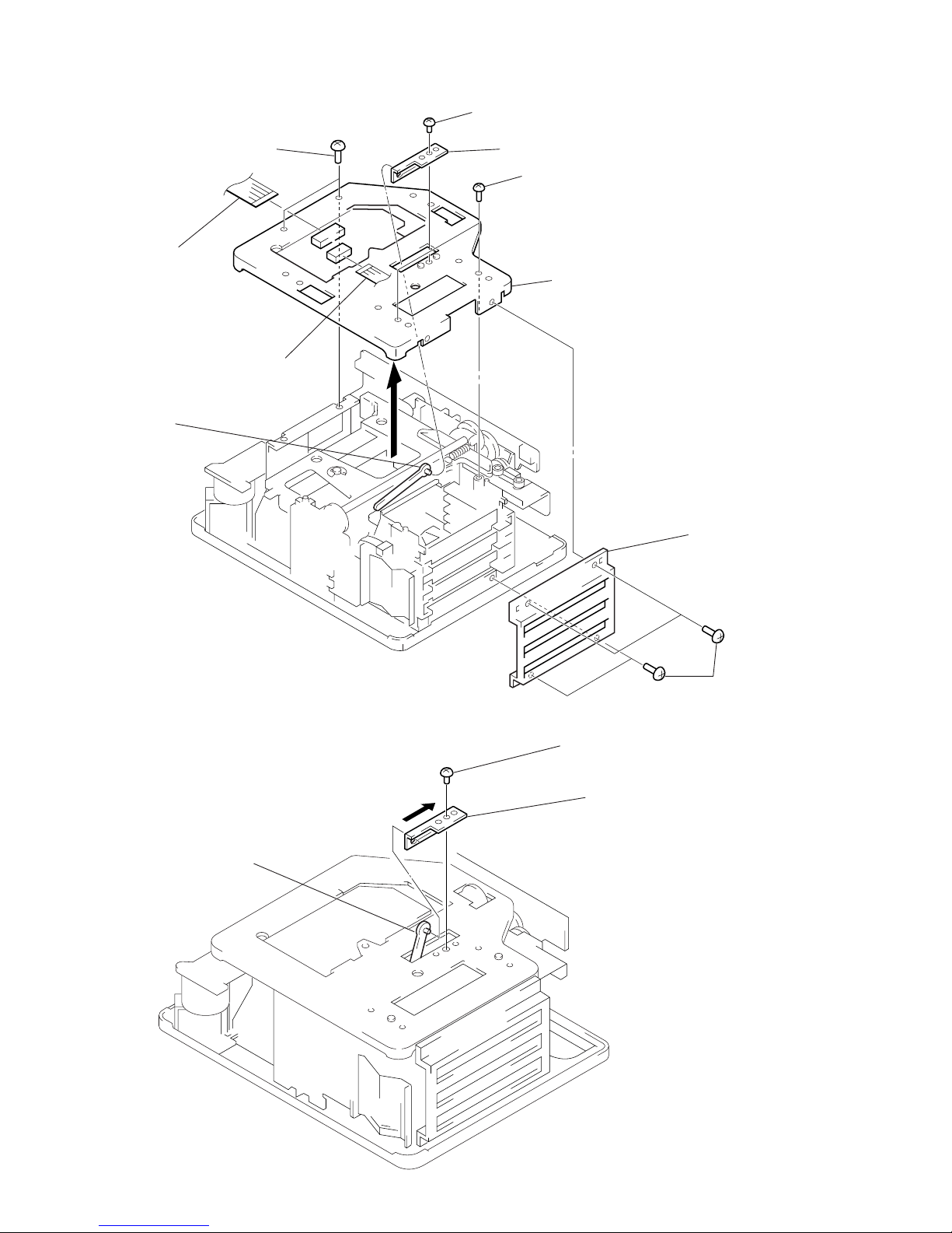
MAIN BOARD, SUB BOARD
1
connector
(CN920)
1
flat wire (11 core)
(CN101)
3
connector
(CN300)
1
connector
(CN900)
2
two screws
(BV3 × 8)
1
connector
(CN112)
6
flat wire (17 core)
(CNP13)
9
SUB board
6
flat wire (23 core)
(CN600)
6
flat wire (17 core)
(CN601)
7
two screws
(BV3 × 8)
6
flat wire (23 core)
(CN500)
1
connector
(CN911)
8
PC board holder
6
connector
(CN912)
7
screw (BV3 × 8)
2
screw (BV3 × 8)
4
two PC board holders
MD MECHANISM DECK SECTION (MDM-C1D)
3
two screws
(BV3 × 8)
1
two screws
(BV3 × 8)
5
two screws
(BV3 × 8)
3
screw
(BV3 × 8)
3
screw
(BV3 × 8)
4
cover (MDM)
5
two screws
(BV3 × 8)
6
MD mechanism deck section
(MDM-C1D)
2
REG 5V, 7V board
1
flat wire (19 core)
(CN401)
5
MAIN board
– 12 –
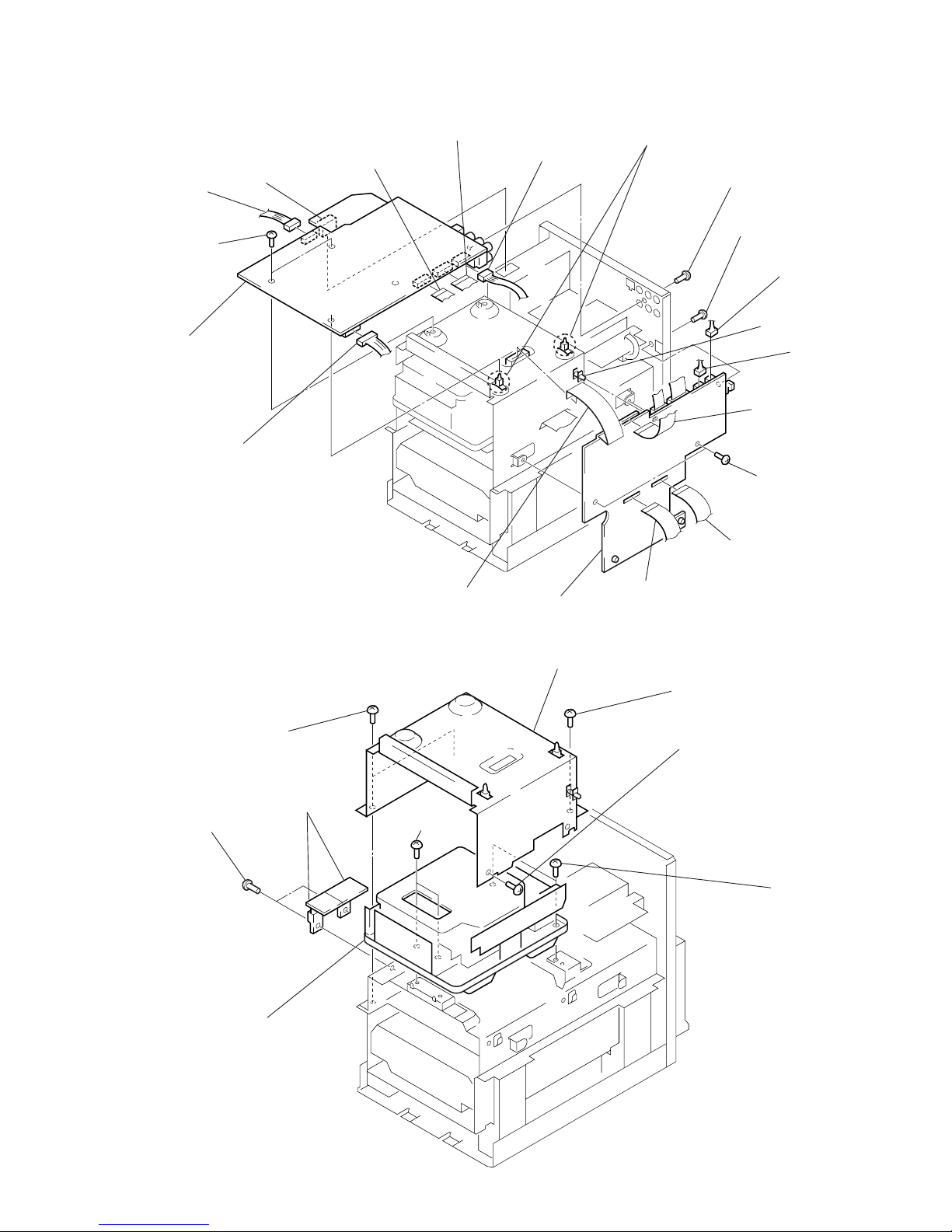
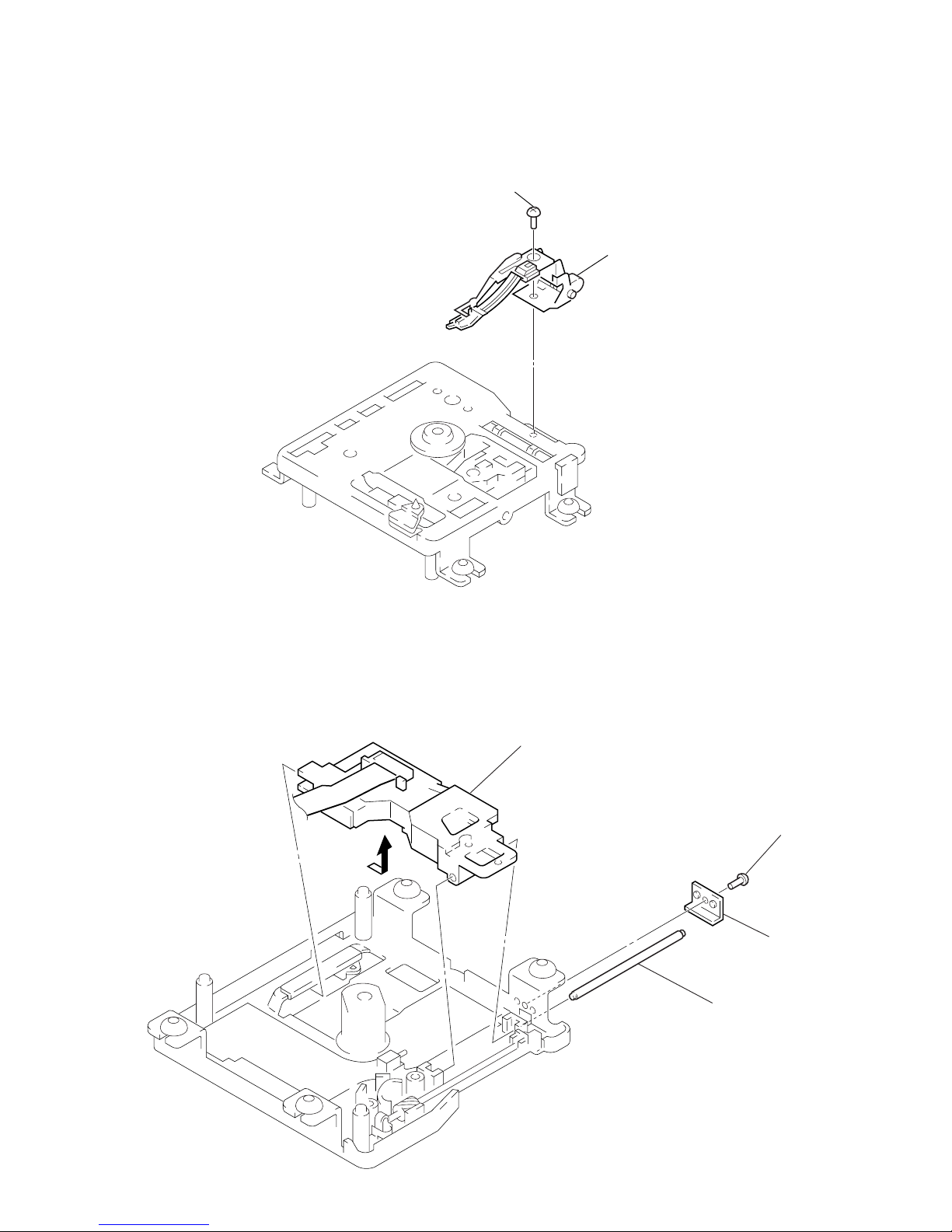
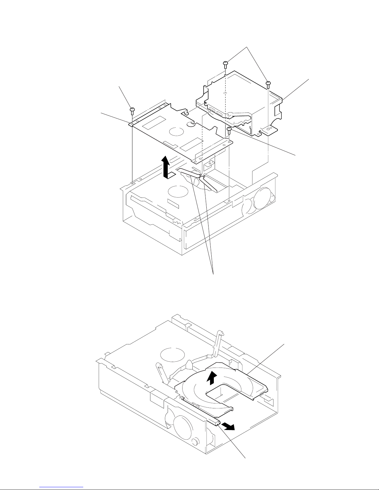
HOLDER (FN), CHASSIS (TOP)
NOTE FOR INSTALLATION OF BRACKET (3)
bracket (3)
lever (s) ass’y
7
two screws
(BVTT2.6 × 5)
8
chassis (TOP)
4
screw
(BVTT2.6 × 5)
7
two screws
(PTP2 × 5)
6
bracket (3)
3
flat wire (13 core)
(CNP12)
3
flat wire (7 core)
(CNP15)
5
lever (S) ass’y
1
four screws
(BVTT2.6 × 5)
2
holder (FN)
screw (BVTT2.6 × 5)
1 Lift up the lever (S) ass’y.
2 Hang the lever (S) ass’y for bracket (3).
3 Slide the lever (S) ass’y to direction of the arrow.
– 13 –
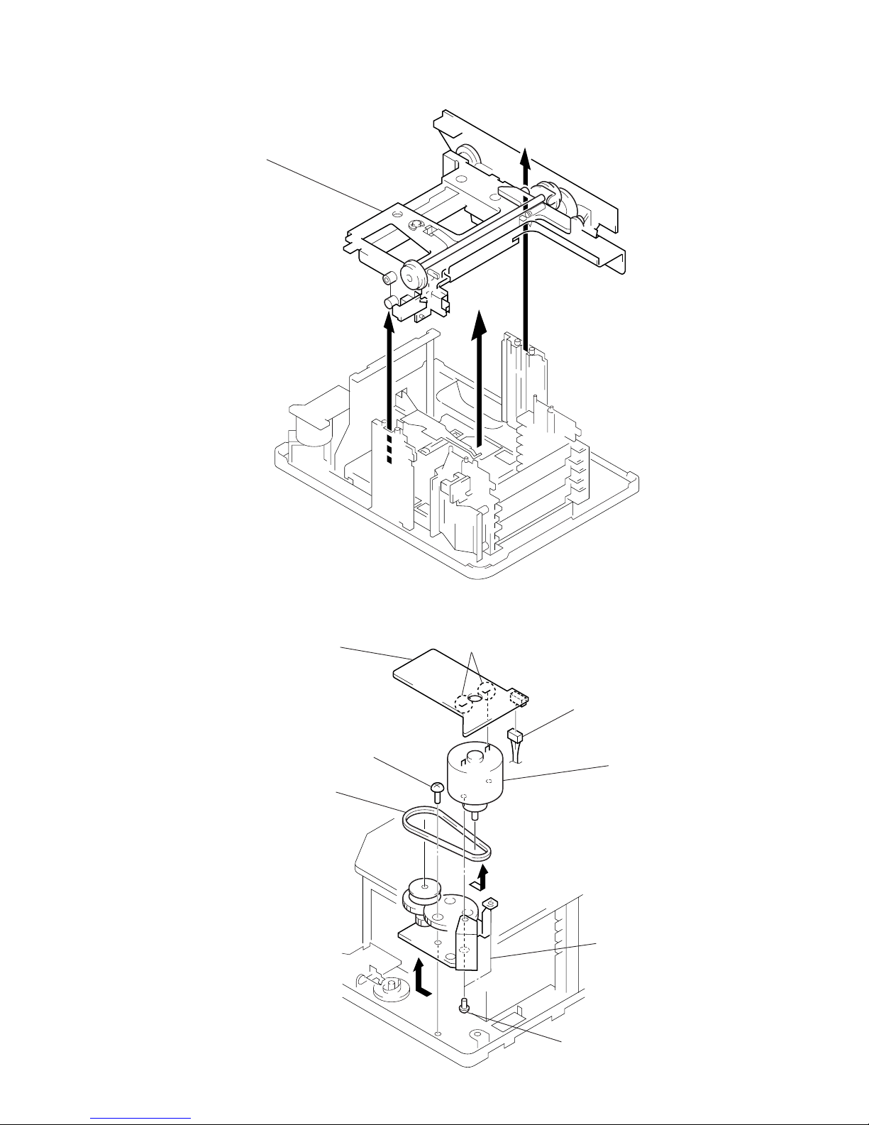
CHASSIS (ELEVATOR) (NEW) ASS’Y
8
MOTOR RELAY board
2
belt A
B
7
Break the soldering of motor.
6
Remove the motor (head)
ass’y to direction of the arrow B.
1
Remove the chassis (elevator) (new)
ass’y to direction of the arrow.
MOTOR (HEAD) ASS’Y (M905)
3
screw
(BVTT2.6 × 5)
5
two screws
(P2 × 2)
A
1
connector (CNP19)
4
Remove the chassis (head gear)
ass’y to direction of the arrow A.
– 14 –
1
two step screws
chassis (elevator)
2
MD base unit
(MBU-C1)
1
two step screws
3
connector
(CN108)
over write head
T ake care not to catch.
3
screw
(BTP2 × 6)
4
BD (MD) board
5
OP translation
flexible board
(CN101)
1
two connectors
(CN104, 109)
2
two precision screws
(P1.7 × 2.5)
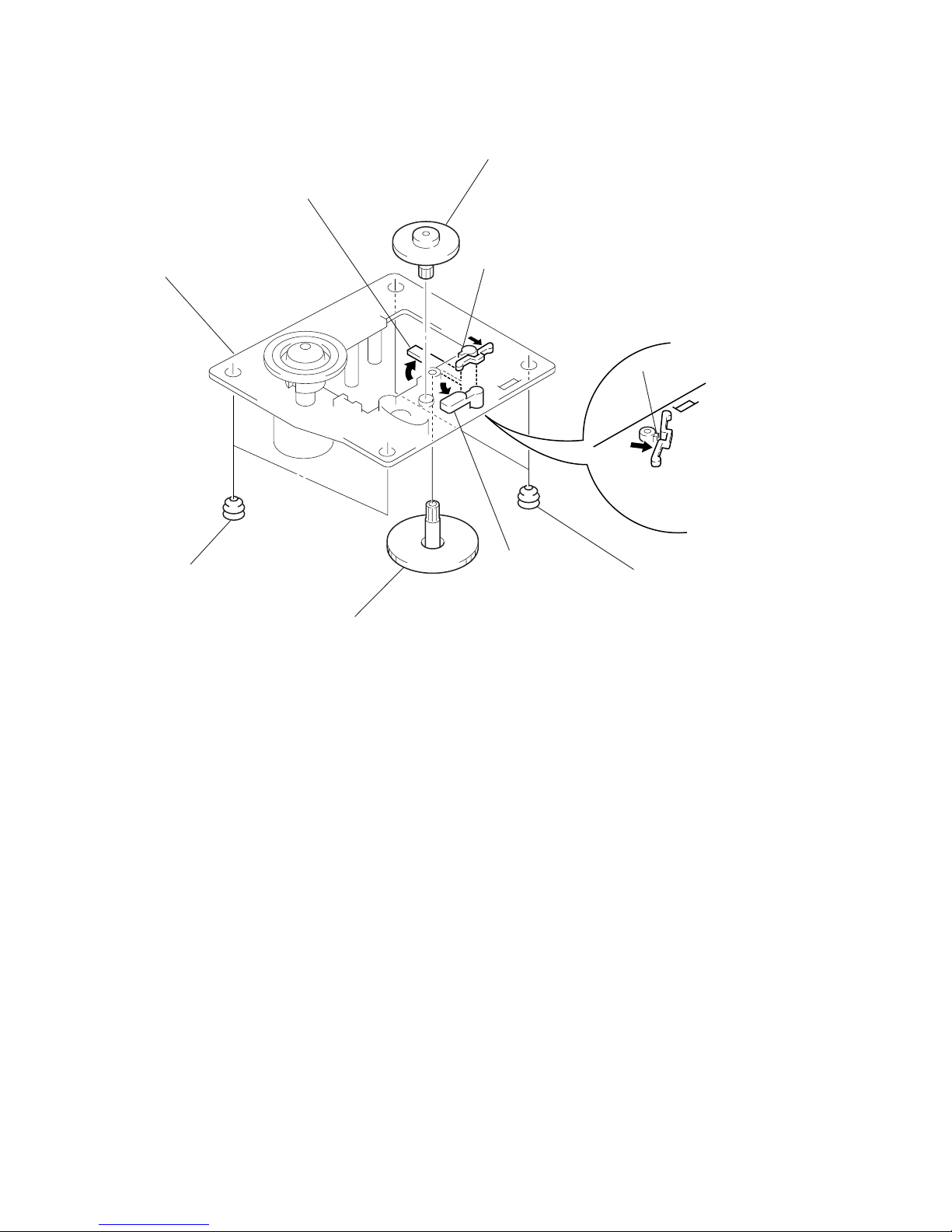
MD BASE UNIT (MBU-C1)
BD (MD) BOARD
– 15 –
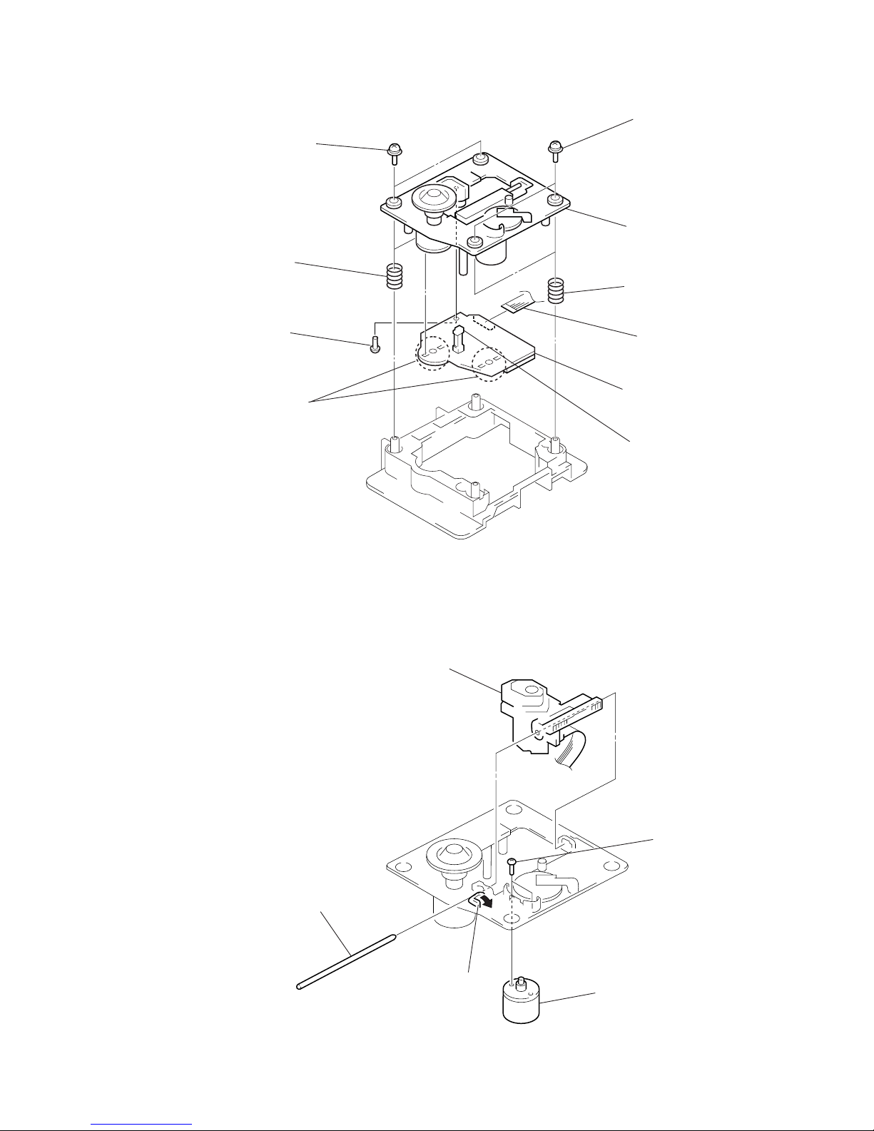
OPTICAL PICK-UP (KMS-260A/J1N) (for MD)
4
Remove the optical pick-up
(KMS- 260A/J1N) (for MD)
to direction of the arrow.
3
shaft (main)
1
screw
(M1.7 × 1.4)
2
stopper
OVER WRITE HEAD (HR901)
2
over write head
(HR901)
1
screw
(P1.7
×
2.5)
– 16 –
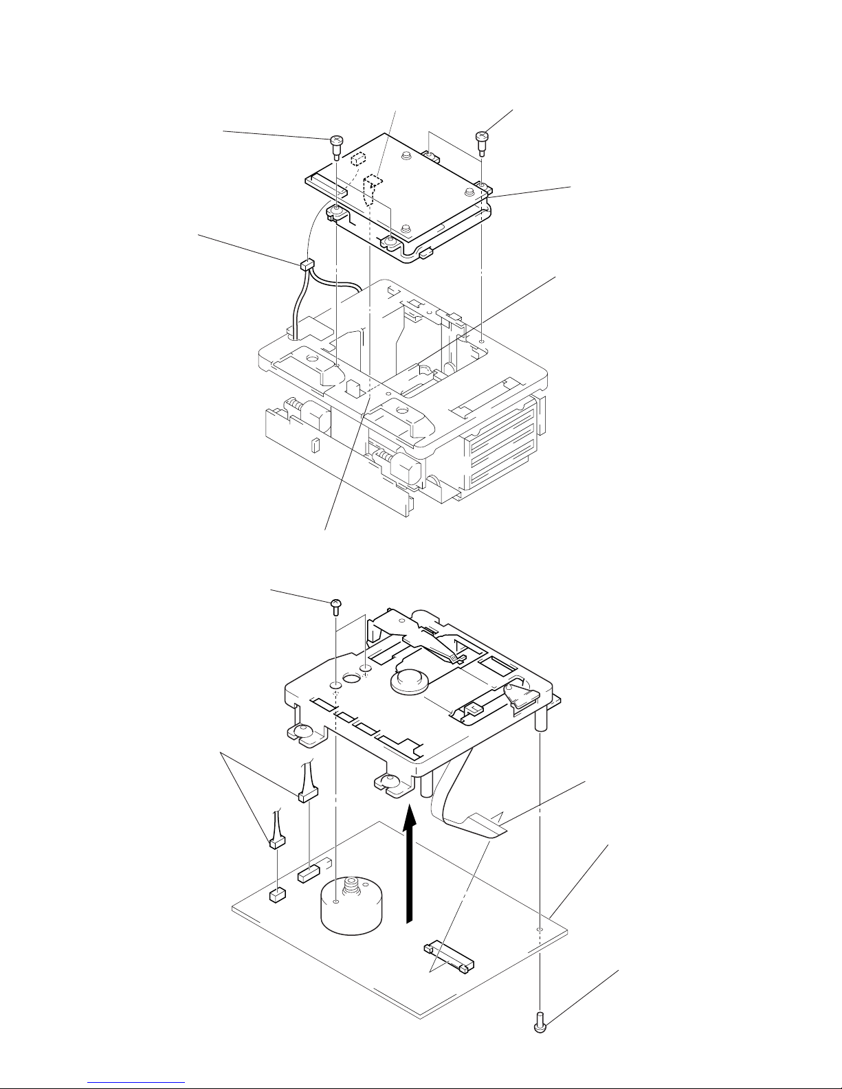
AMP BOARD
7
connector
(CN802)
5
two screws
(BV3 × 8)
6
chassis
5
two screws
(BV3 × 8)
7
connector
(CN801)
5
two screws (BV3 × 8)
8
AMP board
4
Pull the heat sink.
2
cover (back)
1
three screws
(BV3 × 8)
1
two screws
(BV3 × 8)
3
two screws
(BVTT3 × 8)
3
two screws
(BV3 × 8)
CD MECHANISM DECK SECTION (CDM48-5BD29)
2
CD mechanism deck section
(CDM48-5BD29)
1
two screws
(BV3 × 8)
1
two screws
(BV3 × 8)
– 17 –
STOCKER ASS’Y
2
tray (sub) ass’y
1
Pull the slider (selection).
TRAY (SUB) ASS’Y
4
three screws
(BVTT3 × 6)
1
two screws
(BVTT3 × 6)
1
two screws
(BVTT3 × 6)
3
two levers (stock)
5
stocker ass’y
2
Remove the bracket
(sub chassis) to
direction of the arrow.
– 18 –
CD BASE UNIT (BU-5BD29)
5
Remove the CD base unit (BU-5BD29)
to direction of the arrow.
2
two screws
(BV3 × 8)
4
four screws
(BV3 × 8)
1
connector
(CN691)
3
CDM board
1
three connectors
(CN692, 693, 694)
OPTICAL PICK-UP CLEANING
applicator
optical pick-up
Note 1: In cleaning the lens, do not apply an excessive force.
As the optical pick-up is vulnerable, application of
excessive force could damage the lens holder.
Note 2: In cleaning, do not use a cleaner other than exclusive cleaning
liquid (KK-91 or isopropyl alcohol).
Note 3: Wipe the objective lens spirally from center toward outside.
(See Figure A)
(Figure A)
– 19 –
1
two screws
(PTPWH M2.6 × 6)
BD (CD) BOARD
5
screw
(BVTP2.6 × 8)
6
Remove the
four solders.
3
two springs
1
two screws
(PTPWH M2.6 × 6)
2
optical pick-up section
3
two springs
4
flat wire (16 core)
(CN101)
7
BD (CD) board
1
claw
2
sled shaft
3
optical pick-up (KSS-213 BA/F-NP) (for CD)
4
two screws
(P 2 × 3)
5
sled motor
(M102)
limit switch
(S101)
OPTICAL PICK-UP (KSS-213BA/F-NP) (for CD), SLED MOTOR (M102)
– 20 –
SPINDLE MOTOR (M101)
6
Turn the lever.
8
spindle motor
(M101)
1
two insulators (BU)
7
flatness gear (P)
3
Turn the lever.
1
two insulators (BU)
2
claw
4
gear (M)
5
claw
– 21 –
SECTION 4
TEST MODE
4-1. PRECAUTIONS FOR USE OF TEST MODE
1. The erasing-protection tab is not detected in the test mode.
Therefore, operating in the recording laser emission mode and
pressing the REC/CD-MD SYNC button, the recorded contents will be erased regardless of the position of the tab. When
using a disc that is not to be erased in the test mode, be careful
not to enter the continuous recording mode and traverse adjustment mode.
But “CREC MODE”, “EF MO CHECK” and “EF MO ADJUST” is detect the erasing-protection tab and recording laser
power off.
2. Using MD slot is “DISC 1” only.
4-1-1. Recording Laser Emission Mode and Operating
Button
1. Continuous recording mode (CREC MODE)
2. Traverse adjustment mode (EF MO ADJUST)
3. Laser power adjustment mode (LDPWR ADJUST)
4. Laser power check mode (LDPWR CHECK)
5. When pressing the REC/CD-MD SYNC button.
6. Traverse checking mode (EF MO CHECK)
4-2. SETTING THE TEST MODE
1. Turn on the set, and select the MD function.
2. Place the MD in “NO DISC” status (No disc present in stocker
and inside of set)
3. Press DBFB button, DIMMER button, and MD6 button simultaneously to activate the Test mode.
When the Test mode is activated. “TEMP ADJUST” is displayed on fluorescent indicator tube.
4-3. LO ADING/UNLOADING A DISC IN TEST MODE
1. In the Test mode, use the slot 1 only. (Do not load a disc in
other slots.)
2. When a disc is loaded in slot 1, in several seconds it will be
automatically pulled in.
3. To unload a disc, press MD6 button .
4. To load a disc again, press MD6 button .
5. In the Test mode, MD1, 2, 3 LEDs do not light regardless of
whether a disc is present or not.
4-4. RELEASING THE TEST MODE
Press the REPEAT button, and the set returns to normal mode.
(If REPEAT button is pressed with a disc loaded, the disc is automatically ejected.)
4-5. BASIC OPERATIONS OF THE TEST MODE
All operations are performed using the MULTI JOG dial,
ENTER/YES button, and EDIT/NO button. The functions of
these buttons and dial are as follows.
Table 1.
4-6. SELECTING THE TEST MODE
T wenty six test modes are selected by turn the MULTI JOG dial.
Table 2.
• For detailed description of each adjustment mode, refer to the “5.
ELECTRICAL ADJUSTMENTS” (page 24).
• If a different adjustment mode has been selected by mistake, press
the EDIT/NO button to exit from it.
*1: Scurve CHECK, VERIFY CHECK, EEP MODE, MANUAL
CMD, SVDA TA READ, SLED MOVE, ACCESS MODE, 0920
CHECK, Write sure?, HEAD ADJUST, CPLAY2MODE, and
CREC2MODE are not used in servicing. If set accidentally,
press the POWER button immediately to exit it.
Display Contents
TEMP CHECK Temperature compensation offset check
LDPWR CHECK Laser power check
EF MO CHECK Traverse (E-F balance) check
EF CD CHECK Travers (Pre mastered disk) check
FBIAS CHECK Focus bias check
CPLAY MODE Continuous playback mode
CREC MODE Continuous recording mode
Scurve CHECK S-curve check (*1)
VERIFY MODE Non-volatile memory check (*1)
DETRK CHECK Detrack check
TEMP ADJUST Temperature compensation offset adjustment
LDPWR ADJUST Laser power adjustment
EF MO ADJUST Traverse (E-F balance) adjustment
EF CD ADJUST Traverse (Pre mastered disk) adjustment
FBIAS ADJUST Focus bias adjustment
EEP MODE Non-volatile memory mode (*1)
MANUAL CMD Manual command transfer mode (*1)
SVDATA READ Data reading out mode (*1)
ERR DP MODE Operation of error histories memory
SLED MOVE Operation of sled motor (*1)
ACCESS MODE Access check (*1)
0920 CHECK Outermost periphery check (*1)
WRITE sure? Non-volatile memory initialize (*1)
HEAD ADJUST HEAD adjustment check (*1)
CPLAY2MODE Continuous playback mode (*1)
CREC2MODE Continuous recording mode (*1)
Button & dial Function
MULTI JOG dial Changes parameters and modes.
ENTER/YES button
Proceeds onto the next step.
Finalizes input.
EDIT/NO button
Returns to previous step.
Stops operations.
– 22 –
4-8. OPERA TING THE CONTINUOUS RECORDING
MODE
4-8-1. Entering the Continuous Recording Mode
1. Set the MO disc in the slot 1 of unit. (Refer to note 3.)
2. Turn the MULTI JOG dial and display “CREC MODE”.
3. Press the ENTER/YES button to change the display to “CREC
MID”.
4. When access completes, the display changes to “CREC
( )” and REC lights up.
Note: The numbers “ ” displayed shows you the recording position ad-
dress.
4-8-2. Changing the Parts to be Recorded
1. When the ENTER/YES button is pressed during continuous
recording, the display changes as below. (“PROGRAM”
indication turns off during change-over of display.)
4-7. OPERATING THE CONTINUOUS PLAYBACK
MODE
4-7-1. Entering the Continuous Playback Mode
1. Set the disc in the slot 1 of unit. (In several seconds it will be
automatically pulled in.) (Whichever recordable discs or discs
for playback only are available.)
2. Turn the MULTI JOG dial and display “CPLAY MODE”.
3. Press the ENTER/YES button to change the display to “CPLA Y
MID”.
4. When access completes, the display changes to
“C = AD= )”.
Note: The numbers “ ” displayed show you error rates and ADER.
4-7-2. Changing the Parts to be Played-back
1. Press the ENTER/YES button during continuous playback to
change the display as below.
2. When access completes, the display changes to
“C1=
AD= ”.
Note: The numbers “ ” displayed show you error rates and ADER.
4-7-3. Ending the Continuous Playback Mode
1. Pr ess the EDIT/NO button. The display will change to
“CPLA Y MODE”.
2. Press the MD6 button and remove the disc.
Notes:
1. The playback start address for IN, MID, and OUT are as follows.
IN : 40h cluster
MID : 300h cluster
OUT : 700h cluster
In case you want to display the address of the playback position on the
display, press the DISPLAY button and display “CPLA Y (
)”.
2. The EDIT/NO button can be used to stop playing anytime.
2. When access completes, the display changes to “CREC
( )” and REC lights up.
Note: The numbers “ ” displayed shows you the recording position ad-
dress.
4-8-3. Ending the Continuous Recording Mode
1. Press the EDIT/NO b utton. The display will change to “CREC
MODE” and REC goes off.
2. Press the MD 6 button and remove the disc.
Notes:
1. The recording start address for IN, MID, and OUT are as follows.
IN : 40h cluster
MID : 300h cluster
OUT : 700h cluster
2. The EDIT/NO button can be used to stop recording anytime.
3. During the test mode, the erasing-protection tab will not be detected.
Therefore be careful not to set the continuous recording mode when a
disc not to be erased is set in the unit.
4. Do not perform continuous recording for long periods of time above 5
minutes.
5. During continuous recording, be careful not to apply vibration.
4-9. EEP MODE
This mode reads and writes the contents of the non-volatile
memory.
It is not used in servicing. If set accidentally, press the
EDIT/NO button immediately to exit it.
CPLAY MID
CPLAY OUT CPLAY IN
CREC MID
CREC OUT CREC IN
– 23 –
4-10. FUNCTIONS OF OTHER BUTTONS
Table 3.
Note: The erasing-protection tab in not detected during the test mode.
Recording will start regardless of the position of the erasing-protection tab when the REC/CD-MD SYNC button is pressed.
4-11. TEST MODE DISPLAYS
Each time the DISPLAY button pressed, the display changes in
the following order.
Note: Auto gain display and IVR display are not used in servicing.
1. MODE display
Displays “TEMP ADJUST”, “CPLAY MODE”, etc..
2. Error rate display
Error rates are displayed as follows.
C1= AD=
C1= : Indicates C1 error
AD= : Indicates ADER
3. Address display
Address are displayed as follows.
h= a= (MO groove)
With this display, if SHUFFLE button is pressed, the following will be displayed.
h= s= (MO pit and CD)
h=: Header address
a=: ADIP address
s=: SUB Q address
Note: “—” is displayed when the address cannot be read.
4. Auto gain display
Auto gain are displayed as follows.
AG = / [ ]
A B C
A= Focus servo gain coefficient
B= Tracking servo gain coefficient
C= [OK] or [NG] or [ - -] (not converged)
4-12. MEANINGS OF OTHER DISPLAYS
Table 4.
Mode
display
Error rate
display
Address display
ADIP address
display
SUB Q address
display
Auto gain
display
IVR
display
Change over the display with the
SHUFFLE button.
REC
Light Off
(
During continuous
playback (servo all on)
Stop state
(servo all off)
—
Recording mode on
Recording
mode off
—
ALL DISCS
CLV lock state CLV unlock state
—
TRACK
Pit mode Groove mode
—
DISC
High reflection rate
disc
Low reflection rate
disc
—
REPEAT
Spindle servo
CLV-S
(pull-in mode)
Spindle servo
CLV-A
(playing mode)
—
LEVEL-
SYNC
ABCD adjustment
completed
Not adjustment
—
SHUFFLE
Focus auto gain
successful
—
Focus
auto gain
successful.
PROGRAM
Tracking auto gain
successful
—
Tracking
auto gain
failed.
Display
Blinking
Contents
Button Contents
fl
Sets continuous playback when pressed in the STOP
state. (servo all on)
When pressed during continuous playback, the tracking
and sled servo turns on/off.
p
Stop continuous playback and continuous recording.
(servo all off)
)
The sled moves to the outer circumference only when
this is pressed.
0
The sled moves to the inner circumference only when
this is pressed.
REC/CD-MD
SYNC
Turns recording on/off when pressed during continuous
playback.
SHUFFLE
Switches between the pit and groove modes when
pressed.
CONTINUE
Switches between the CLV-S (pull-in mode) and CLVA (playing servo) modes when pressed. (Switches the
spindle servo mode.)
DISPLAY
Switches the display when pressed.
Returns to previous step. Stop operations.
REPEAT
Releasing the test mode
6
Disc eject
– 24 –
SECTION 5
ELECTRICAL ADJUSTMENTS
Optical pick-up flexible board
Table 1.
Optical
BD (MD) board
Pick-up
IC171 D101 IC101, IC121, IC192
1. Temperature
compensation × ®® ®
offset adjustment
2. Laser power
®®× ®
adjustment
3. Traverse
®®× ®
adjustment
4. Focus bias
®®× ®
adjustment
5. Error rate check ®®× ®
Pick-up
Laser tap
Flexible boar
d
1. PRECAUTIONS FOR CHECKING LASER DIODE EMISSION
T o check the emission of the laser diode during adjustments, nev er
view directly from the top as this may lose your eyesight.
2. PRECAUTIONS FOR USE OF OPTICAL
PICK-UP (KMS-260A)
As the laser diode in the optical pick-up is easily damaged by
static electricity, solder the laser tap of the flexible board when
using it.
Before disconnecting the connector, desolder first. Before connecting the connector, be careful not to remove the solder. Also
tale adequate measures to prevent damage by static electricity.
Handle the flexible board with care as it breaks easily.
3. PRECAUTIONS FOR ADJUSTMENTS
1) When replacing the following parts, perform the adjustments
and checks with ® in the order shown in the following table.
2) Set the test mode when performing adjustments.
After completing the adjustments, exit the test mode.
3) Perform the adjustments in the order shown.
4) Use the following tools and measuring devices.
• Test disc (CD for playback only) TDYS-1
(Parts No. 4-963-646-01)
• Laser power meter LPM-8001
(Parts No. J-2501-046-A)
• Oscilloscope (Measure after preforming CAL of prove.)
• Digital voltmeter
• Thermometer
5) When observing several signals on the oscilloscope, etc., make
sure that VC and ground do not connect inside the oscilloscope.
(VC and ground will become short-circuited)
4. CREATING MO CONTINUOUSLY RECORDED
DISC
* This disc is used in focus bias adjustment and error rate check.
The following describes how to create a MO continuous recording disc.
1. Insert a MO disc (blank disc) commercially available to MD
slot 1.
2. Turn the MULTI JOG dial and display “CREC MODE”.
3. Press the ENTER/YES button and display “CREC MID”.
“CREC (0300)” is displayed for a moment and recording starts.
4. Complete recording within 5 minutes.
5. Press the EDIT/NO button and stop recording.
6. Press the MD6 button and remove the MO disc.
The above has been how to create a continuous recording data for
the focus bias adjustment and error rate check.
Note: Be careful not to apply vibration during continuous recording.
MD SECTION
– 25 –
Optical pick-up
objective lens
laser
power meter
10. Press the EDIT/NO button and display “LDPWR CHECK”,
and stop the laser emission.
(The EDIT/NO button is effective at all times to stop the
laser emission.)
5. TEMPERATURE COMPENSATION OFFSET
ADJUSTMENT
Save the temperature data at that time in the non-volatile memory
as 25°C reference data.
Notes:
1. Usually, do not perform this adjustment.
2. Perform this adjustment in an ambient temperature of 22 °C to 28 °C.
Perform it immediately after the power is turned on when the internal
temperature of the unit is the same as the ambient temperature of 22
°C to 28 °C.
3. When D101 has been replaced, perform this adjustment after the tem-
perature of this part has become the ambient temperature.
Adjusting Method:
1. Turn the MULTI JOG dial and display “TEMP ADJUST”.
2. Press the ENTER/YES button and select the “TEMP AD-
JUST” mode.
3. “TEMP =
” and the current temperature a data will be dis-
played.
4. To save the data, press the ENTER/YES button.
When not saving the data, press the EDIT/NO button.
5. When the ENTER/YES button is pressed, “TEMP=
SAVE” will be displayed for some time, followed by “TEMP
ADJUST”.
When the EDIT/NO button is pressed, “TEMP ADJUST”
will be displayed immediately.
Specifications:
The temperature should be within “E0-EF”, “F0-FF”, “00-0F”,
“10-1F” and “20-2F”.
Adjusting Method:
1. Set the laser power meter on the objective lens of the optical
pick-up. (When it cannot be set properly, press the ) button
or 0 button and move the optical pick-up.)
Connect the digital voltmeter to CN110 pin 5 (I+3 V) and
CN110 pin 4 (IOP) of the BD (MD) board.
2. Turn the MULTI JOG dial and display “LDPWR ADJUST”.
(Laser power: for adjustment)
3. Press the ENTER/YES button and display “LD 0.9 mW $ ”.
4. Turn the MULTI JOG dial so that the reading of the laser
power meter becomes 0.82 to 0.93 mW.
Set the range control on the laser power meter to 10 mW, then
press the ENTER/YES button to save the adjustment result
in the non- volatile memory.
(“LD SAVE $ ” will be displayed for a moment.)
5. Then “LD 7.0 mW $
”will be displayed.
6. Turn the MULTI JOG dial so that the reading of the laser
power meter becomes 6.9 to 7.1 mW, press the
ENTER/YES button and save the adjustment result in the
nonvolatile memory.
(“LD SAVE $ ” will be displayed for a moment.)
Note: Do not perform the emission with 7.0 mW more than 15
seconds continuously.
7. Turn the MULTI JOG dial and display “LDPWR CHECK”.
8. Press the ENTER/YES button and display “LD 0.9 mW $ ”.
Check that the reading of the laser power meter becomes 0.80
to 0.96 mW.
9. Press the ENTER/YES button and display “LD 7.0 mW $ ”.
Check that the reading of the laser power meter and digital
voltmeter satisfy the specified value.
Specification:
Laser power meter reading : 7.0 ± 0.2 mW
Digital voltmeter reading : Optical pick-up displayed value ±10%
6. LASER POWER ADJUSTMENT
Connection:
+
–
BD (MD) board
digital voltmeter
TP29 (IOP +)
TP30 (IOP –)
KMS260A
27X40
B0567
lOP=56.7 mA in this case
lOP (mA) = Digital voltmeter reading (mV)/1 (Ω)
(Optical pick-up label)
– 26 –
Connection:
A
B
VC
specification: A=B
(T r averse W a vef orm)
(T r averse W a vef orm)
A
B
VC
specification: A=B
Adjusting Method:
(T r averse W av eform)
A
B
VC
specification: A=B
18. Press the ENTER/YES button, and save the result of adjustment to the non-volatile memory.
(“EFB= SAVE” will be displayed for a moment. Then “EF
CD ADJUST” will be displayed.)
19. Press the MD6 button and remove the test disc TDYS-1.
(T ra v erse W a vef orm)
A
B
VC
specification: A=B
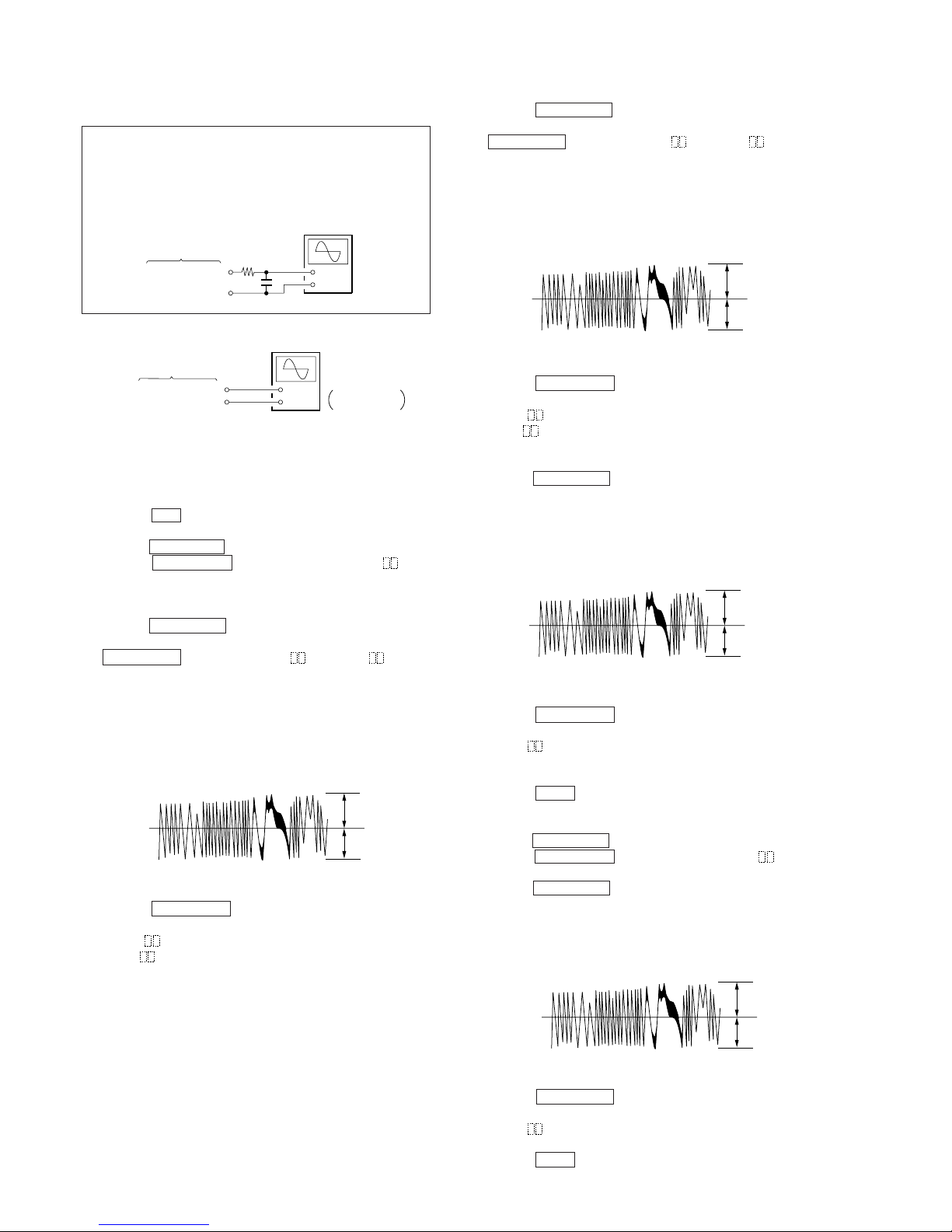
7. TRAVERSE (E-F BALANCE) ADJUSTMENT
Note 1: Data will be erased during MO reading if a recorded
disc is used in this adjustment.
Note 2: If the traverse waveform is not clear, connect the os-
cilloscope as shown in the following figure so that it
can be seen more clearly.
1. Connect an oscilloscope to TP69 (TEO) and TP58 (VC) of the
BD (MD) board.
2. Load a MO disc (any available on the market) to MD slot 1.
(Refer to note 1.)
3. Press the ) button and move the optical pick-up outside
the pit.
4. Turn the MULTI JOG dial and display “EFBAL ADJUST”.
5. Press the ENTER/YES button and display “EFB=
MOR”.
(Laser power READ power/Focus servo ON/tracking servo
OFF/spindle (S) servo ON)
6. Turn the MULTI JOG dial so that the waveforms of the oscilloscope becomes the specified value. (When the
MULTI JOG dial is turned , the “ ” of “EFB= MO-R”
changes and the waveform changes.)
In this adjustment, waveform varies at intervals of approx. 2%.
Adjust the waveform so that the specified value is satisfied as
much as possible.
(MO read power traverse adjustment)
7. Press the ENTER/YES button, and save the result of adjustment to the non-volatile memory.
(“EFB=
SAVE” will be displayed for a moment. Then
“EFB= MO-W” will be displayed.)
8. Turn the MULTI JOG dial so that the waveforms of the oscilloscope becomes the specified value. (When the
MULTI JOG dial is turned, the “
” of “EFB= MO-W”
changes and the waveform changes.)
In this adjustment, waveform varies at intervals of approx.
2%. Adjust the waveform so that the specified value is satisfied as much as possible.
(MO write power traverse adjustment)
9. Press the ENTER/YES button, and save the result of adjustment to the non-volatile memory.
(“EFB= SAVE” will be displayed for a moment. Then
“EFB= MO-P” will be displayed.)
10. The optical pick-up moves to the pit area automatically and
servo is imposed.
11. Turn the MULTI JOG dial until the waveforms of the oscilloscope moves closer to the specified value.
In this adjustment, waveform varies at intervals of approx. 2%.
Adjust the waveform so that the specified value is satisfied as
much as possible.
12. Press the ENTER/YES button, and save the result of adjustment to the non-volatile memory.
(“EFB= SAVE” will be displayed for a moment. Then “EF
MO ADJUST” will be displayed.)
The disc stops rotating automatically.
13. Press the MD6 button and remove the MO disc.
14. Set the test mode again and load the test disc TDYS-1 to MD
slot 1.
15. Turn the MULTI JOG dial and display “EF CD ADJUST”
16. Press the ENTER/YES button and display “EFB= CD”.
Servo is imposed automatically.
17. Turn the MULTI JOG dial until the waveforms of the oscilloscope moves closer to the specified value.
In this adjustment, waveform varies at intervals of approx. 2%.
Adjust the waveform so that the specified value is satisfied as
much as possible.
+
–
oscilloscope
(DC range)
10 pF
330 k
Ω
TP69 (TEO)
TP58 (VC)
BD (MD) board
+
–
BD (MD) board
TP69 (TEO)
TP58 (VC)
oscilloscope
(DC range)
V: 0.1 V/div
H: 10 ms/div
– 27 –
9. ERROR RATE CHECK
9-1. CD Error Rate Check
Checking Method:
1. Load a test disc TDYS-1.
2. Turn the MULTI JOG dial and display “CPLAY MODE”.
3. Press the ENTER/YES button and display “CPLAY MID”.
4. “C1=
AD= ” is displayed.
5. Check that the C1 error is below 20.
6. Press the EDIT/NO button, stop playback, press the MD6
button, and remove the test disc.
9-2. MO Error Rate Check
Checking Method:
1. Load a continuously recorded disc (Refer to “5-4. Creating
MO Continuously Recorded Disc”.).
2. Turn the MULTI JOG dial and display “CPLAY MODE”.
3. Press the ENTER/YES button and display “CPLAY MID”.
4. “C1=
AD= ” is displayed.
5. If the C1 error is below 50, check that ADER is 00.
6. Press the EDIT/NO button, stop playback, press
the MD6 button, and remove the continuously recorded disc.
10. FOCUS BIAS CHECK
Change the focus bias and check the focus tolerance amount.
Checking Method:
1. Load a continuously recorded disc (Refer to “5-4. Creating
MO Continuously Recorded Disc”.).
2. Turn the MULTI JOG dial and display “CPLAY MODE”.
3. Press the ENTER/YES button and display “CPLAY MID”.
4. Press the EDIT/NO button when “C1=
AD= ” is
displayed.
5. Turn the MULTI JOG dial and display “FBIAS CHECK”.
6. Press the ENTER/YES button and display “ / c= ”.
The first four digits indicate the C1 error rate, the two digits
after [/] indicate ADER, and the 2 digits after [c=] indicate the
focus bias value.
Check that the C1 error is below 50 and ADER is 00.
7. Press the ENTER/YES button and display “ / b= ”.
Check that the C1 error is not below 100 and ADER is not
above 02 every time.
8. Press the ENTER/YES button and display “ / a= ”.
Check that the C1 error is not below 100 and ADER is not
above 02 every time.
9. Press the EDIT/NO button, next press the MD6 button, and
remove the continuously recorded disc.
Note 1: If the C1 error and ADER are above 00 at points a or b,
the focus bias adjustment may not have been carried out
properly. Adjust perform the beginning again.
C1 error
220
bca
Focus bias value
(F. BIAS)
8. FOCUS BIAS ADJUSTMENT
Adjusting Method:
1. Load a continuously recorded disc (Refer to “4. Creating MO
Continuously Recorded Disc”.).
2. Turn the MULTI JOG dial and display “CPLAY MODE”.
3. Press the ENTER/YES button and display “CPLAY MID”.
4. Press the EDIT/NO button when “C1=
AD=
” is
displayed.
5. Turn the MULTI JOG dial and display “FBIAS ADJUST”.
6. Press the ENTER/YES button and display “
/
a=
”.
The first four digits indicate the C1 error rate, the two digits
after [/] indicate ADER, and the 2 digits after [a=] indicate the
focus bias value.
7. Turn right the MULTI JOG dial and find the focus bias value
at which the C1 error rate becomes 220. (Refer to note 2.)
8. Press the ENTER/YES button and display “ / b= ”.
9. Turn left the MULTI JOG dial and find the focus bias value
at which the C1 error rate becomes 220. (Refer to note 2.)
10. Press the ENTER/YES button and display “ / c= ”.
11. Check that the C1 error rate is below 50 and ADER is 00.
Then press the ENTER/YES button.
12. If the “( )” in “ - -
(
)” is above 20, press the
ENTER/YES button.
If below 20, press the EDIT/NO button and repeat the adjustment from step 2 again.
13. Press the EDIT/NO button and press the MD6 button to
remove the continuously recorded disc.
Note 1: The relation between the C1 error and focus bias is as
shown in the following figure. Find points a and b in the
following figure using the above adjustment. The focal
point position c is automatically calculated from points a
and b.
Note 2: As the C1 error rate changes, perform the adjustment us-
ing the average vale.
– 28 –
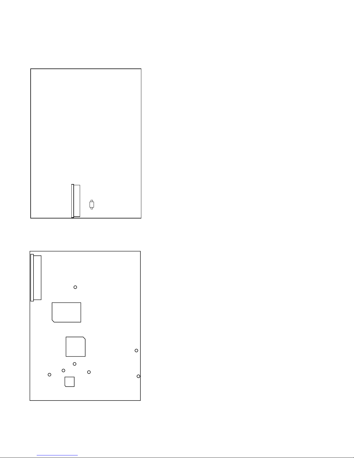
11. ADJUSTING POINTS AND
CONNECTING POINTS
[BD (MD) BOARD] – SIDE A –
[BD (MD) BOARD] – SIDE B –
CN107
GND
IC316
IC121
TP95
(RF)
TP67
(FEO)
TP71
(TEO)
TP30
(IOP–)
TP29
(IOP+)
TP58
(VC)
IC101
CN101
D101
– 29 –
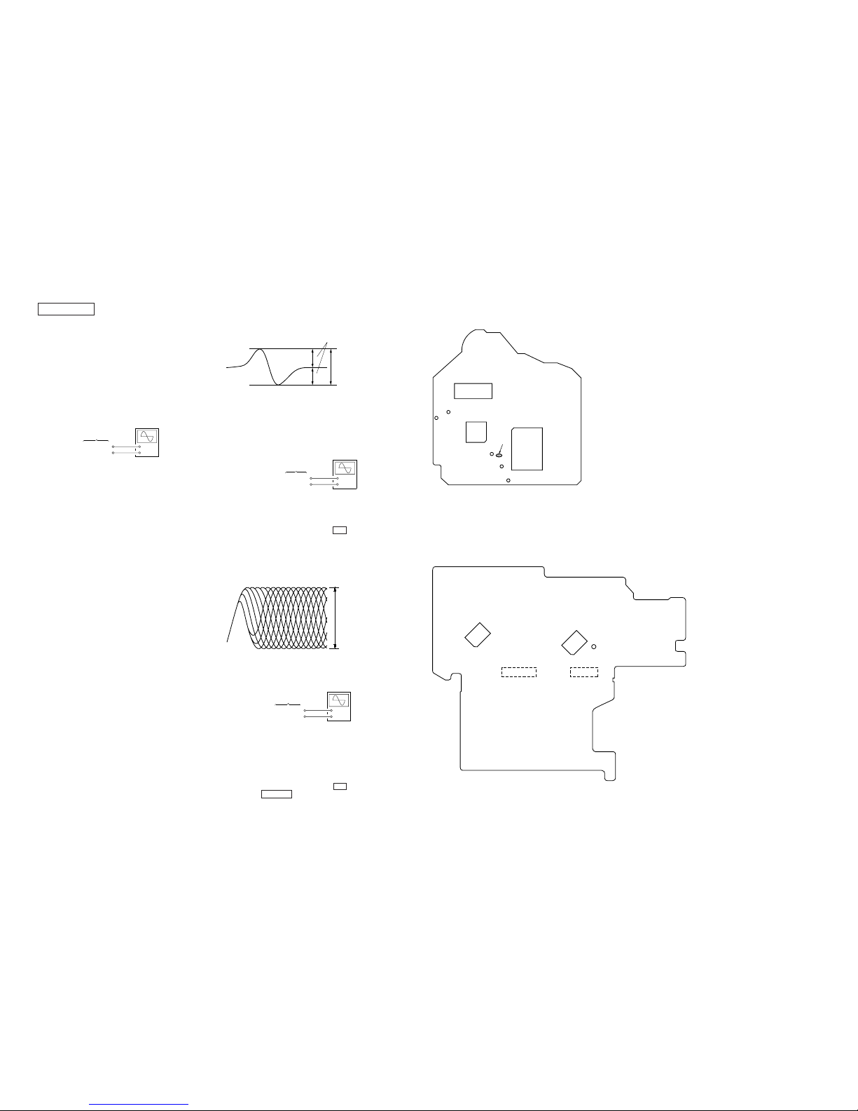
– 30 –
[BD (CD) BOARD] – Side B –
Notes:
1. CD Block basically constructed to operated without adjustment.
Therefore, check eaech item in order given.
2. Use YEDS-18 disc (Part No.: 3-702-101-01) unless otherwise
indicated.
3. Use the oscilloscope with more than 10 MΩ impedance.
4. Clean an object lens by an applicator with neutral detergent
when the signal level is low than specified value with the following checks.
CD SECTION
1. S-Curve CHECK
Connection:
Procedure:
1. Connect the oscilloscope to TP (FEO) and TP (VC) on BD
(CD) board.
2. Connect the TP (FOK) and TP (GND) with lead wire.
3. Turned power switch on.
4. Put disc (YEDS-18) in and turned power switch on again and
actuate the focus search. (actuate the focus search when disc
table is moving in and out.)
5. Confirm that the oscilloscope waveform (S-curve) is symmetrical between A and B. And confirm peak to peak level within
2.4 ± 0.7 Vp-p.
S-curve waveform
6. After check, remove the lead wire connected in step 2.
Note: • Try to measure several times to make sure that the ratio
of A : B or B : A is more than 10 : 7.
• Take sweep time as long as possible and light up the brightness to obtain best waveform.
2. RF LEVEL CHECK
Connection:
Procedure:
1. Connect the oscilloscope to TP (RF) and TP (VC) on BD (CD)
board.
2. Turned power switch on. (stop mode)
3. Put disc (YEDS-18) in and press the ^ button.
4. Confirm that oscilloscope waveform is clear and check RF
signal level is correct or not.
Note: Clear RF signal waveform means that the shape “≈” can
be clearly distinguished at the center of the waveform.
RF signal waveform
3. E-F BALANCE (TRAVERSE) CHECK
Connection:
+
–
BD (CD) board
TP (FEO)
TP (VC)
oscilloscope
A
B
symmetry
+
–
BD (CD) board
TP (RF)
TP (VC)
oscilloscope
+
–
BD (CD) board
TP (TEO)
TP (VC)
oscilloscope
(DC range)
VOLT/DIV: 200 mV
TIME/DIV: 500 ns
(with the 10 : 1 probe
in use)
1.3 ± 0.3 Vp-p
within 2.4 ± 0.7 Vp-p
Procedure:
1. Connect the lead wire to TP607. (on the SUB board)
2. Connect the oscilloscope to TP (TEO) and TP (VC) on BD
(CD) board.
3. Turned power switch on.
4. Select the CD function.
5. Connect the lead wire to ground (from TP607)
6. Put disc (YEDS-18) in and press the ^ button.
7. Press the DISPLAY button. (Tracking servo and sled servo
are turned off.)
8. Confirm that the oscilloscope waveform is symmetrical on the
top and bottom in relation to 0 Vdc, and check this level.
9. Release the lead wire.
4. CONNECTING POINTS
[SUB BOARD] – Conductor Side –
GND
VC
TEO
FEO
IC103
IC101
FOK
RF
IC102
IC500
IC600
TP607
CN600
CN601
 Loading...