

Sony HCD-MD5 Schematic

SERVICE MANUAL
HCD-MD5 is the amplifier, CD, MD
and tuner section in DHC-MD5.
HCD-MD5
AEP Model
UK Model
E Model
Tourist Model
US and foreign patents licensed from Dolby
Laboratories Licensing Corporation.
Amplifier section
DIN power output 40 W + 40 W
(6 ohms, at 1 kHz, DIN)
Continuous RMS power output
50 + 50 watts
(6 ohms at 1 kHz, 10% THD)
Peak music power output
700 watts
Music power output 160 watts
Inputs VIDEO/GAME IN
(phono jacks)
(switchable)
VIDEO IN:
voltage 250 mV,
impedance 47 kilohms
GAME IN:
voltage 450 mV,
impedance 47 kilohms
T APE IN (phono jacks):
voltage 250mV,
impedance 47 kilohms
Outputs T APE OUT (phono jacks):
voltage 250 mV
impedance 1 kilohms
PHONES (stereo phone jack):
accepts headphones of
8 ohms or more.
SPEAKER: accepts impedance of 6 to
16 ohms.
Model Name Using Similar Mechanism HCD-W55
CD
Section
MD
Section
CD Mechanism Type
Base Unit Name BU-5BD19
Optical Pick-up Name KSS-213B/K-N
Model Name Using Similar Mechanism NEW
MD Mechanism Type MDM-2FR
Base Unit Name MBU-2F
Optical Pick-up Name KMS-210A/J-N
SPECIFICATIONS
CD player section
System Compact disc and digital
Laser Semiconductor laser
Laser output Max. 44.6 µW*
Frequency response 2 Hz – 20 kHz (±0.5 dB)
CD OPTICAL DIGITAL OUT
(Square optical connector jack, rear panel)
audio system
(λ=780 nm)
Emission duration:
continuous
*This output is the value
measured at a distance of
200 mm from the objective
lens surface on the Optical
Pick-up Block with 7 mm
aperture.
MINI Hi-Fi COMPONENT SYSTEM
CDM38A-5BD19
MD deck section
System MiniDisc digital audio
system
Laser Semiconductor laser
(λ=780 nm)
Emission duration:
continuous
Laser output Max. 44.6 µW*
*This output is the value
measured at a distance of
200 mm from the objective
lens surface on the Optical
Pick-up Block with a
7 mm aperture.
Recording time 74 minutes max. (using
MDW-74)
Sampling frequency 44.1 kHz
Frequency response 5 Hz to 20 kHz
– Continued on next page –
MICROFILM
SECTION 3
DISASSEMBLY
Note: Follow the disassembly procedure in the numerical order given.
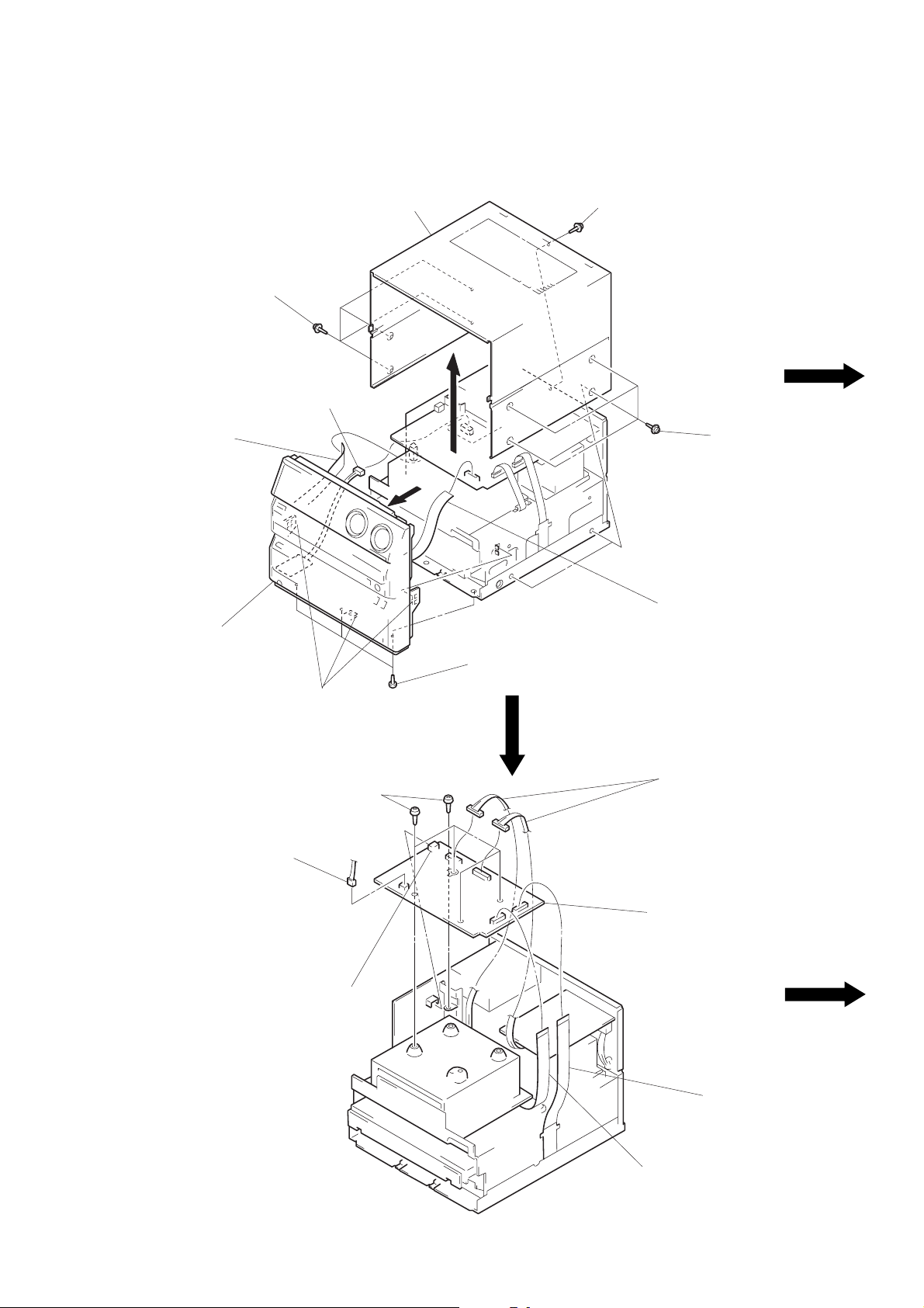
CASE, FRONT PANEL ASS’Y
1
four screws
(CASE 3 TP2)
4
connector
(CN906)
3
flat wire (22 core)
(CN103)
2
case
1
four screws
(CASE 3 TP2)
1
four screws
(CASE 3 TP2)
7
front panel ass‘y
POWER BOARD
1
connector
(CN881)
6
three claws
3
4
connector
(CN804)
five screws
×
8)
(BV3
5
three screws
(BV3
3
flat wire (19 core)
(CN805)
×
8)
1
two connectors
(CN802, 803)
5
POWER board
– 7 –
2
2
flat wire (23 core)
(CN808)
flat wire (21 core)
(CN807)
BRACKET (MAIN) SECTION
6
bracket (MAIN)
section
5
three screws
×
8)
(BV3
3
cover (FFC)
4
flat wire (21 core)
(CN807)
1
three screws
(BV3
1
2
supplied OPT cap
×
8)
four screws
×
8)
(BV3
SHIELD CASE (MD)
1
two screws
(BV3
5
three screws
×
8)
(BV3
1
eight screws
(BV3
×
8)
2
shield case
(MD)
×
8)
– 8 –
CD MECHANISM
2
CD mechanism
1
two boss
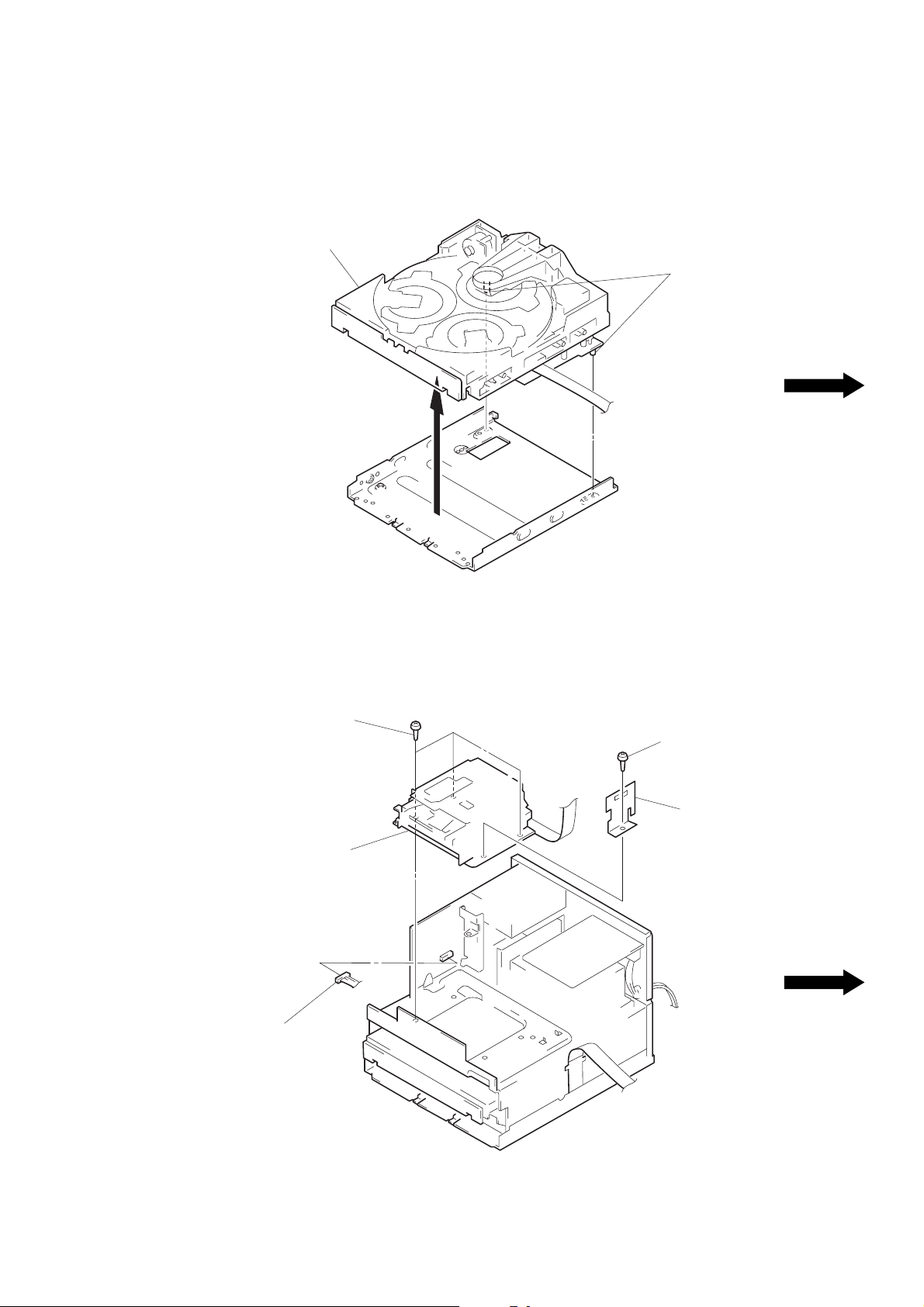
MD MECHANISM SECTION
2
three screws
(BV3
4
MD mechanism
section
1
connector
(CN101)
×
8)
2
screw
(BV3
×
8)
3
cover (MDM)
(AEP, UK, German)
– 9 –

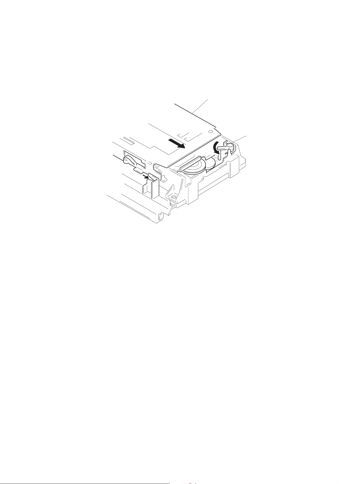
DISC TRAY
4
two claws
3
flat wire (8 core)
2
Pull the disc tray.
5
Remove the disc tray.
flat wire
claw
A
claw
B
Note: When mounting the disc tray, route a flat
cable through claw
in the figure.
1
Rotate the cam to direction
of the arrow.
A
and B as shown
MD MECHANISM
4
two screws
×
18)
(B2.6
5
two
collars
7
MD mechanism
5
two collars
4
two screws
(B2.6
×
18)
B
2
connector (CN251)
3
flat wire (30 core)
(CN202)
3
flat wire (18 core)
(CN221)
6
1
Turn the lever (SLM) toward
direction
(M) assembly toward direction
screw (BTT2.6 × 4)
A
, and slide the slider
A
B
Slider (M) ass’y
lever (SLM)
.
– 10 –

INSTALLATION DISC TRAY
Note: When mounting the disc tray, the collars
A
and B must be engaged in the grooves
respectively .
callar
A
ditch
callar
B
SLIDER (M) ASS’Y
claw
claw
B
C
claw
A
1
Remove a torsion coil
spling from the claw
2
Disengaging the claw B,
raise the lever (SLM) upw ard
to remove.
A
.
A
– 11 –
B
3
Slide the claw C of the slider
(M) assembly up the base
groove in direction
raise the slider (M) assembly
in direction
base groove
B
to remove.
A
, and
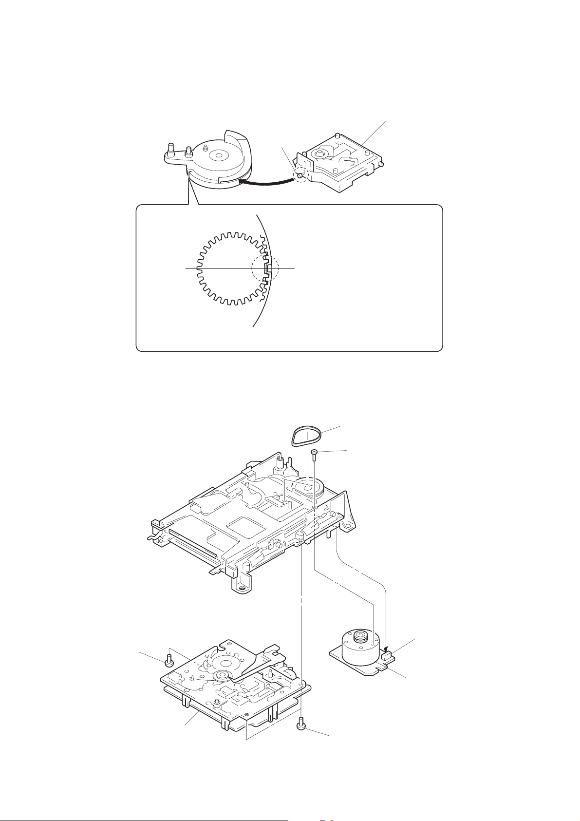
INSTALLATION BU CAM ASS’Y BASE UNIT, ROTALY ENCODER
portion A
When mounting the BU cam assembly,
it must be engaged with the rotaly
encorder switch as shown.
When mounting the base unit, insert the
portion A into a groove in the BU cam.
BASE UNIT, LOADING MOTOR ASS’Y
1
screws
×
6)
(BV3
3
belt
4
two screws
(B2.6
×
5)
5
connector
(CN192)
6
loading motor ass’y
2
base unit
– 12 –
1
screw
(BV3
×
6)
INSTALLATION SLIDER (M) ASS’Y
B
2
Slide the slider (M) assembly
toward direction
be locked with the lev er (SLM).
A
B
unit it can
1
Turn fully the lever (SLM)
toward direction
A
.
– 13 –
 Loading...