

Sony HCDMD-5 Service manual

SERVICE MANUAL
HCD-MD5 is the amplifier, CD, MD
and tuner section in DHC-MD5.
HCD-MD5
AEP Model
UK Model
E Model
Tourist Model
US and foreign patents licensed from Dolby
Laboratories Licensing Corporation.
Amplifier section
DIN power output 40 W + 40 W
(6 ohms, at 1 kHz, DIN)
Continuous RMS power output
50 + 50 watts
(6 ohms at 1 kHz, 10% THD)
Peak music power output
700 watts
Music power output 160 watts
Inputs VIDEO/GAME IN
(phono jacks)
(switchable)
VIDEO IN:
voltage 250 mV,
impedance 47 kilohms
GAME IN:
voltage 450 mV,
impedance 47 kilohms
T APE IN (phono jacks):
voltage 250mV,
impedance 47 kilohms
Outputs T APE OUT (phono jacks):
voltage 250 mV
impedance 1 kilohms
PHONES (stereo phone jack):
accepts headphones of
8 ohms or more.
SPEAKER: accepts impedance of 6 to
16 ohms.
Model Name Using Similar Mechanism HCD-W55
CD
Section
MD
Section
CD Mechanism Type
Base Unit Name BU-5BD19
Optical Pick-up Name KSS-213B/K-N
Model Name Using Similar Mechanism NEW
MD Mechanism Type MDM-2FR
Base Unit Name MBU-2F
Optical Pick-up Name KMS-210A/J-N
SPECIFICATIONS
CD player section
System Compact disc and digital
Laser Semiconductor laser
Laser output Max. 44.6 µW*
Frequency response 2 Hz – 20 kHz (±0.5 dB)
CD OPTICAL DIGITAL OUT
(Square optical connector jack, rear panel)
audio system
(λ=780 nm)
Emission duration:
continuous
*This output is the value
measured at a distance of
200 mm from the objective
lens surface on the Optical
Pick-up Block with 7 mm
aperture.
MINI Hi-Fi COMPONENT SYSTEM
CDM38A-5BD19
MD deck section
System MiniDisc digital audio
system
Laser Semiconductor laser
(λ=780 nm)
Emission duration:
continuous
Laser output Max. 44.6 µW*
*This output is the value
measured at a distance of
200 mm from the objective
lens surface on the Optical
Pick-up Block with a
7 mm aperture.
Recording time 74 minutes max. (using
MDW-74)
Sampling frequency 44.1 kHz
Frequency response 5 Hz to 20 kHz
– Continued on next page –
MICROFILM

Tuner section
FM stereo, FM/AM superheterodyne tuner
FM tuner section
Tuning range
Tourist model: 76.0 – 108.0 MHz (50 kHz step)
Other models: 87.5 – 108.0 MHz (50 kHz step)
Aerial FM lead aerial
Aerial terminals 75 ohm unbalanced
Intermediate frequency 10.7 MHz
TABLE OF CONTENTS
1. SERVICING NOTES
.................................................. 3
2. GENERAL
Index to Parts and Controls ............................................... 5
3. DISASSEMBLY............................................................ 7
AM tuner section
Tuning range
German model:
AM: 522 – 1,611 kHz
AEP, UK models:
MW: 522 – 1,611 kHz
LW: 144 – 288 kHz
Tourist model:
AM: 531 – 1,602 kHz
Malaysia, Singapore,
Saudi Arabia,
Hong Kong models:
MW: 531 – 1,602 kHz
SW: 5.95 – 17.90 MHz
Aerial AM loop aerial
Intermediate frequency 450 kHz
General
Power requirements 220 – 230 V AC, 50/60 Hz
Power consumption 85 watts (Tourist model)
Dimensions
Amplifier/Tuner/MD/CD section:
Mass
Amplifier/Tuner/MD/CD section:
Supplied accessories: AM loop aerial (1)
(with the interval set at 9 kHz)
(with the interval set at 9 kHz)
(with the interval set at 3 kHz)
(with the interval set at 9 kHz)
530 –1,710 kHz
(with the interval set at 10 kHz)
(with the interval set at 9 kHz)
530 – 1,710 kHz
(with the interval set at 10 kHz)
External aerial terminals
(AEP, German model)
110 – 120 V or 220 – 240 V AC,
50/60 Hz Adjustable with the
voltage selector (Other model)
130 watts (Other models)
Approx. 280 × 240 × 360 mm
1
/8 × 9 1/2 × 14 1/4 in) (w/h/d) incl.
(11
projecting parts and
controls
(U.K., Hong Kong model)
Approx. 280 × 240 × 350 mm
1
/8 × 9 1/2 × 13 7/8 in) (w/h/d) incl.
(11
projecting parts and
controls (Other models)
Approx. 9.4 kg
(20 lb 12 oz)
Remote RM-S5MD (1)
Sony SUM-3 (NS)
batteries (2)
FM lead aerial (1)
Speaker cords (2)
4. TEST MODE ................................................................. 14
5. ELECTRICAL ADJUSTMENTS
MD Section........................................................................ 20
Tuner Section..................................................................... 25
CD Section......................................................................... 26
6. DIAGRAMS
6-1. Block Diagrams
CD Section......................................................................... 29
Tuner Section..................................................................... 31
MD Section........................................................................ 35
Main Section...................................................................... 39
6-2. Schematic Diagram – Tuner Section –
(AEP, G, UK model).......................................................... 44
6-3. Printed Wiring Board – Tuner Section –
(AEP, G, UK model).......................................................... 46
6-4. Printed Wiring Board – Tuner Section –
(EXCEPT AEP, G, UK model) .......................................... 47
6-5. Schematic Diagram – Tuner Section –
(EXCEPT AEP, G, UK model) .......................................... 48
6-6. Printed Wiring Board – CD Section – ............................... 50
6-7. Schematic Diagram – CD Section – .................................. 53
6-8. Printed Wiring Board –MD Section – ............................... 56
6-9. Schematic Diagram –MD Section – .................................. 59
6-10. Schematic Diagram – Digital Section – ............................ 63
6-11. Printed Wiring Boards – Digital Section – ........................ 67
6-12. Schematic Diagram – Relay Section – .............................. 70
6-13. Printed Wiring Board – Relay Section – ........................... 73
6-14. Printed Wiring Board – Main Section – ............................ 76
6-15. Schematic Diagram – Main Section –............................... 79
6-16. Schematic Diagram – Power Section – ............................. 83
6-17. Printed Wiring Boards – Power Section – ......................... 87
6-18. Schematic Diagram – Power AMP Section –.................... 92
6-19. Printed Wiring Boards – Power AMP Section –................ 95
6-20. Schematic Diagram – Panel Section –............................... 99
6-21. Printed Wiring Boards – Panel Section – ........................ 103
6-22. IC Pin Function Description............................................ 109
7. EXPLODED VIEWS ................................................. 123
8. ELECTRICAL PARTS LIST .................................. 132
Design and specifications are subject to change without notice.
– 2 –
SECTION 1
SERVICING NOTES
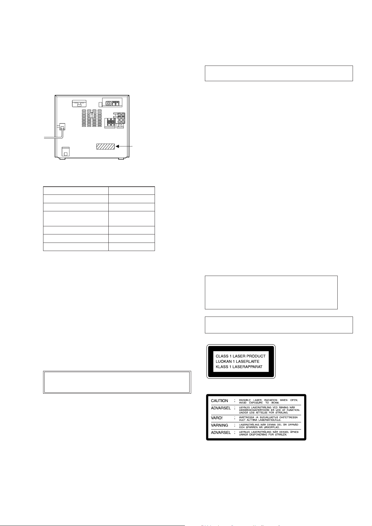
MODEL IDENTIFICATION
— BACK PANEL —
Parts No.
MODEL PARTS No
AEP model 4-984-208-1π
UK model 4-984-208-2π
Saudi Arabia, Singapore, 4-984-208-3π
Malaysia model
German model 4-984-208-4π
Hong Kong model 4-984-208-5π
Tourist model 4-984-208-7π
NOTES ON HANDLING THE OPTICAL PICK-UP
BLOCK OR BASE UNIT
The laser diode in the optical pick-up block may suffer electrostatic
break-down because of the potential difference generated by the
charged electrostatic load, etc. on clothing and the human body.
During repair, pay attention to electrostatic break-down and also
use the procedure in the printed matter which is included in the
repair parts.
The flexible board is easily damaged and should be handled with
care.
NOTES ON LASER DIODE EMISSION CHECK
The laser beam on this model is concentrated so as to be focused on
the disc reflective surface by the objective lens in the optical pickup block. Therefore, when checking the laser diode emission, observe from more than 30 cm away from the objective lens.
Notes on chip component replacement
• Never reuse a disconnected chip component.
• Notice that the minus side of a tantalum capacitor may be dam-
aged by heat.
Flexible Circuit Board Repairing
• Keep the temperature of soldering iron around 270 ˚C during re-
pairing.
• Do not touch the soldering iron on the same conductor of the
circuit board (within 3 times).
• Be careful not to apply force on the conductor when soldering or
unsoldering.
Note:
Be sure to connect all wires (including FFC) in the MD
section before applying power or ICs may be damaged.
SAFETY-RELATED COMPONENT WARNING!!
COMPONENTS IDENTIFIED BY MARK ! OR DOTTED
LINE WITH MARK ! ON THE SCHEMATIC DIAGRAMS
AND IN THE PARTS LIST ARE CRITICAL TO SAFE
OPERATION. REPLACE THESE COMPONENTS WITH
SONY PARTS WHOSE PART NUMBERS APPEAR AS
SHOWN IN THIS MANU AL OR IN SUPPLEMENTS PUBLISHED BY SONY.
CAUTION
Use of controls or adjustments or performance of procedures other than those specified herein may result in
hazardous radiation exposure.
Laser component in this product is capable of emitting radiation exceding the limit for Class 1.
This appliance is classified as a
CLASS 1 LASER product.
The CLASS 1 LASER PRODUCT MARKING is located on the
rear exterior.
This caution label
is located inside
the unit.
– 3 –
COLD START METHOD
While pressing the POWER key, insert the AC plug cord into the
AC outlet. Cold start will be set.
Note :
As cold start will erase all the preset contents etc., do not set it in
normal operations.
FORCED RESET SWITCH
The switch on the power board (S101) is the forced reset switch for
IC201.
Press it for about one second after turning on the power after disassembling and assembling the unit again.
• Parts Location
[POWER BOARD] — Component side —
CN803 CN802
S101
RESET
Switch
IC821
CN807
IC102
CN808
– 4 –

EXCEPT AEP,
l
German, UK mode
SECTION 2
GENERAL
This section is extracted
from instruction manual.
Rear Panel
6
AEP, German, UK model
67
8
4
5
123
1 CD OPTICAL DIGITAL OUT jack
2 SPEAKER connectors
(Malaysia, singapore, Saudi Arabia, Hong Kong, Tourist model)
3 AU BUS connector
4 TAPE input/output jack
5 VIDEO GAME/VCR connectors
6 Aerial terminals
7 SIGNAL Ground terminal
8 VOLTAGE SELECTOR
· (MD play) button
∏ (MD pause) button
π (MD stop) button
§ (MD EJECT) button
MD slot
!∞ SYSTEM POWER switch
!§ FUNCTION button
!¶ MD control button
Controls
Front Panel
Index to Parts and
!• DBFB button
!ª GROOVE button
@º CD SYNC button
@¡ r REC button
@™ PHONES jack
@£ LOOP button
· (CD play) button
∏ (CD pause) button
π (CD stop) button
§ (CD EJECT) button
@¢ EX-CHANGE button
@∞ DISC SKIP button
@§ CD control button
@¶ DISC 1-3 buttons
@• DISC TRAY
1 TUNER/BAND button
2 PLAY MODE/TUNING MODE button
3 REPEAT/STEREO/MONO button
4 1/ALL DISCS button
5 DISPLAY button
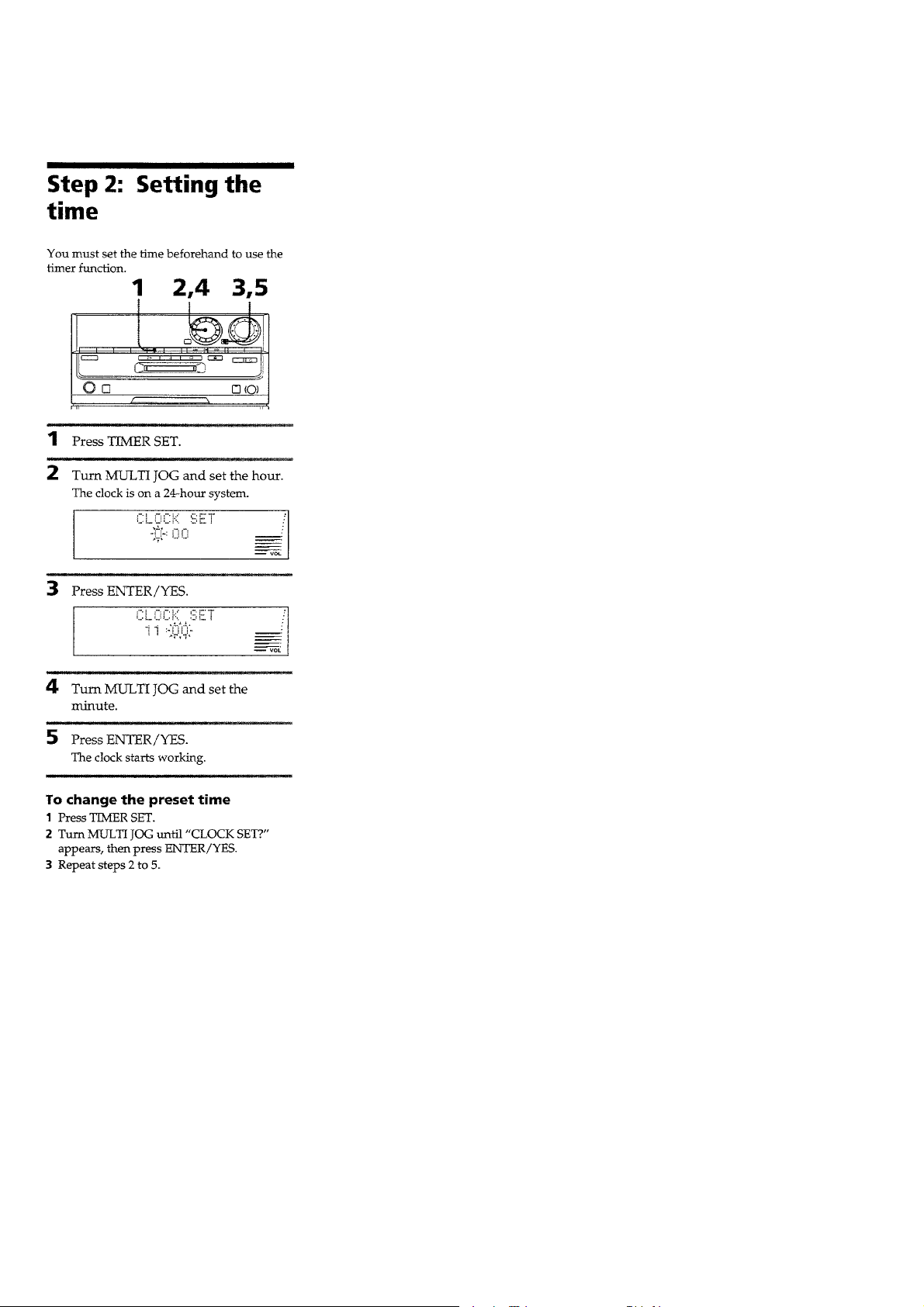
6 TIMER SET button
7 TIMER SELECT button
←/→ CUSOR button
!™ VOLUME control
8 EDIT/NO button
9 MULTI JOG control
0 ENTER/YES button
!£ CHARACTER button
!¡ º/‚ (fast backward/fast forward)
!¢ PRESET EQ button
– 5 –
– 6 –
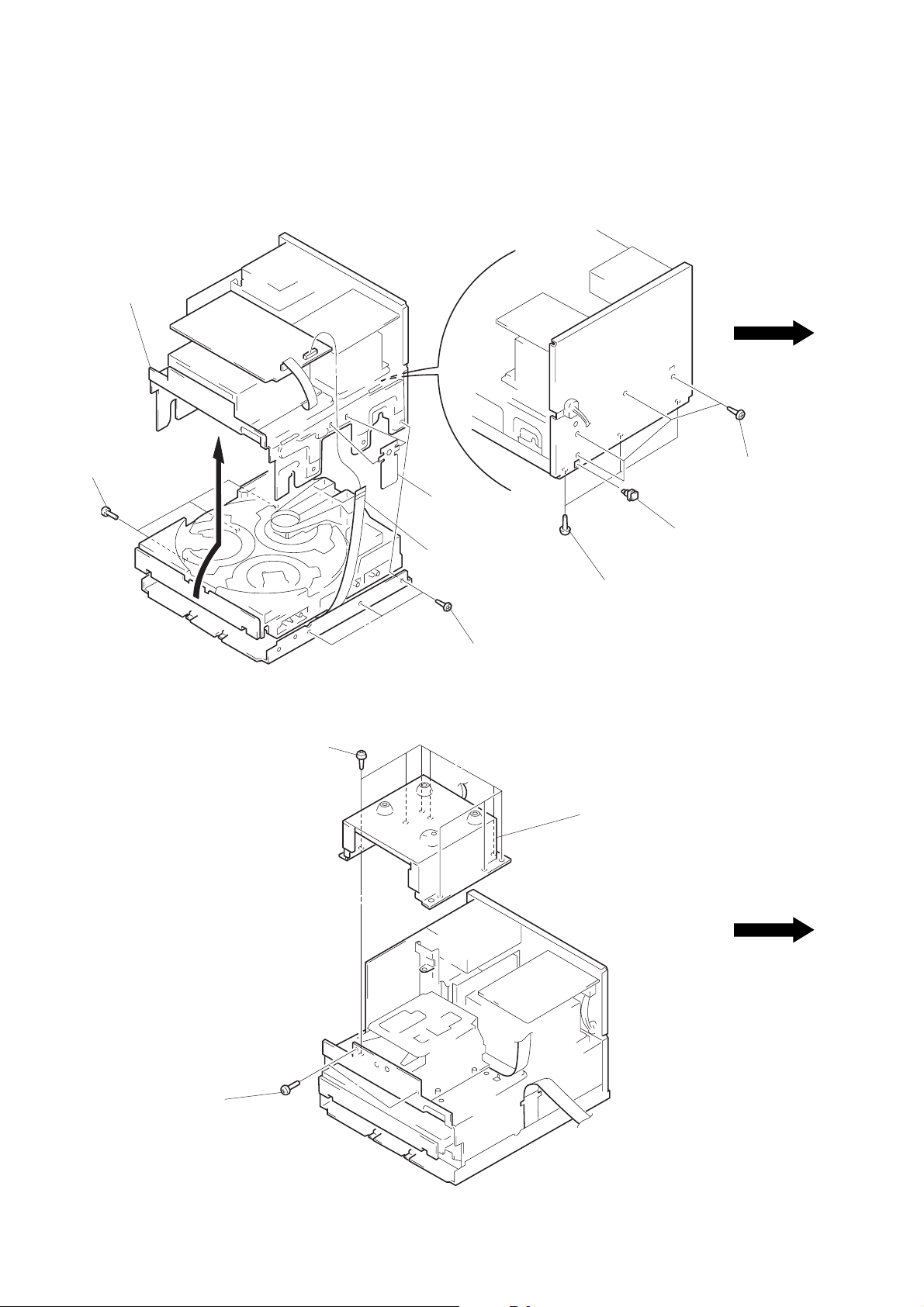
SECTION 3
DISASSEMBLY
Note: Follow the disassembly procedure in the numerical order given.
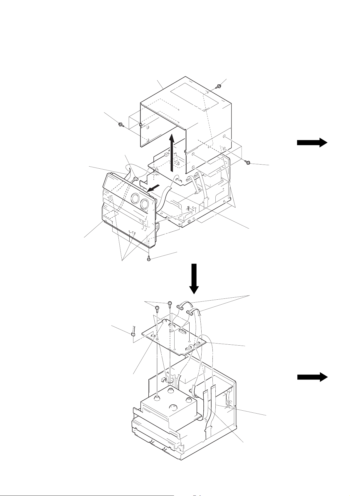
CASE, FRONT PANEL ASS’Y
1
four screws
(CASE 3 TP2)
4
connector
(CN906)
3
flat wire (22 core)
(CN103)
2
case
1
four screws
(CASE 3 TP2)
1
four screws
(CASE 3 TP2)
7
front panel ass‘y
POWER BOARD
1
connector
(CN881)
6
three claws
3
4
connector
(CN804)
five screws
×
8)
(BV3
5
three screws
(BV3
3
flat wire (19 core)
(CN805)
×
8)
1
two connectors
(CN802, 803)
5
POWER board
– 7 –
2
2
flat wire (23 core)
(CN808)
flat wire (21 core)
(CN807)
BRACKET (MAIN) SECTION
6
bracket (MAIN)
section
5
three screws
×
8)
(BV3
3
cover (FFC)
4
flat wire (21 core)
(CN807)
1
three screws
(BV3
1
2
supplied OPT cap
×
8)
four screws
×
8)
(BV3
SHIELD CASE (MD)
1
two screws
(BV3
5
three screws
×
8)
(BV3
1
eight screws
(BV3
×
8)
2
shield case
(MD)
×
8)
– 8 –
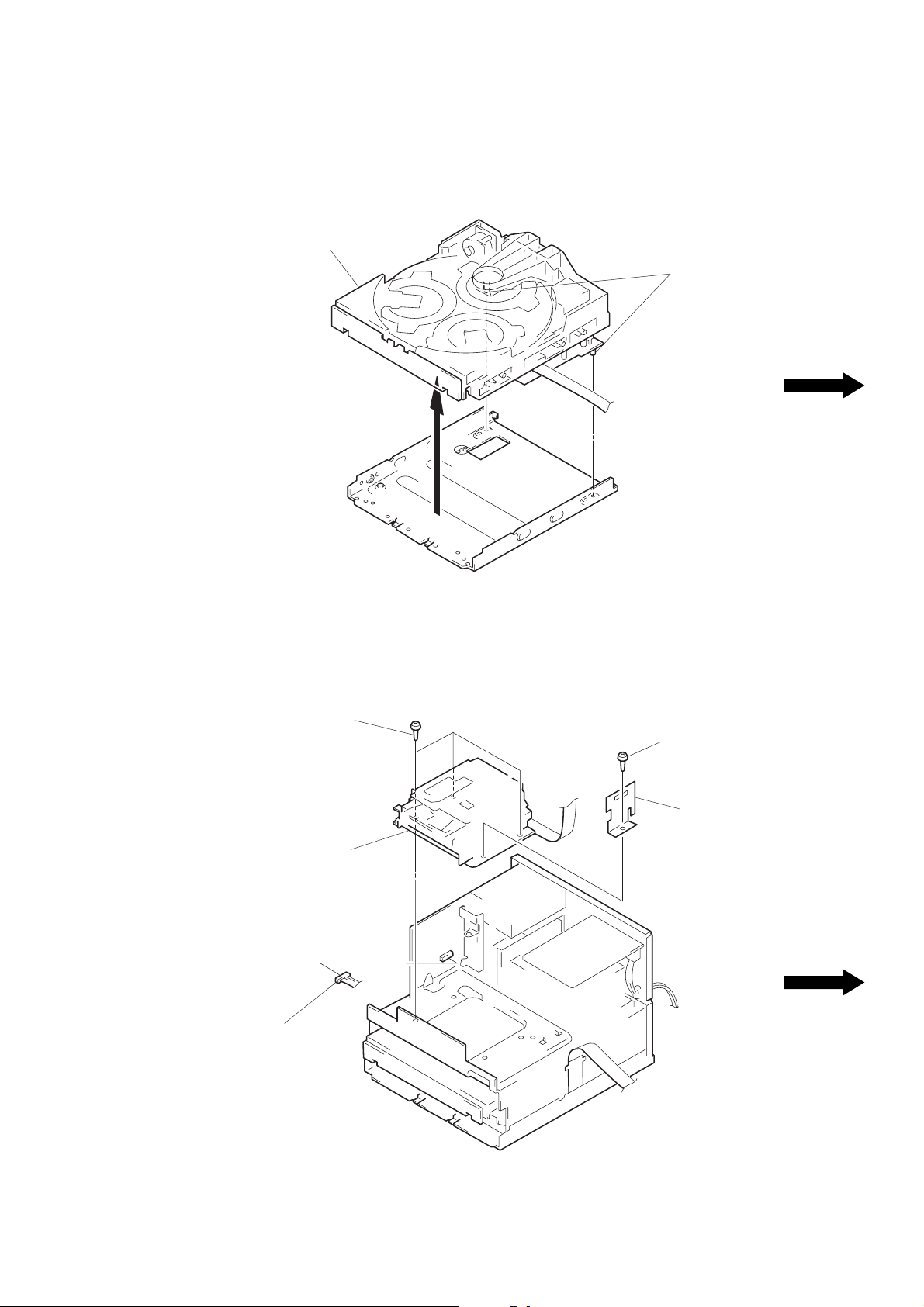
CD MECHANISM
2
CD mechanism
1
two boss
MD MECHANISM SECTION
2
three screws
(BV3
4
MD mechanism
section
1
connector
(CN101)
×
8)
2
screw
(BV3
×
8)
3
cover (MDM)
(AEP, UK, German)
– 9 –

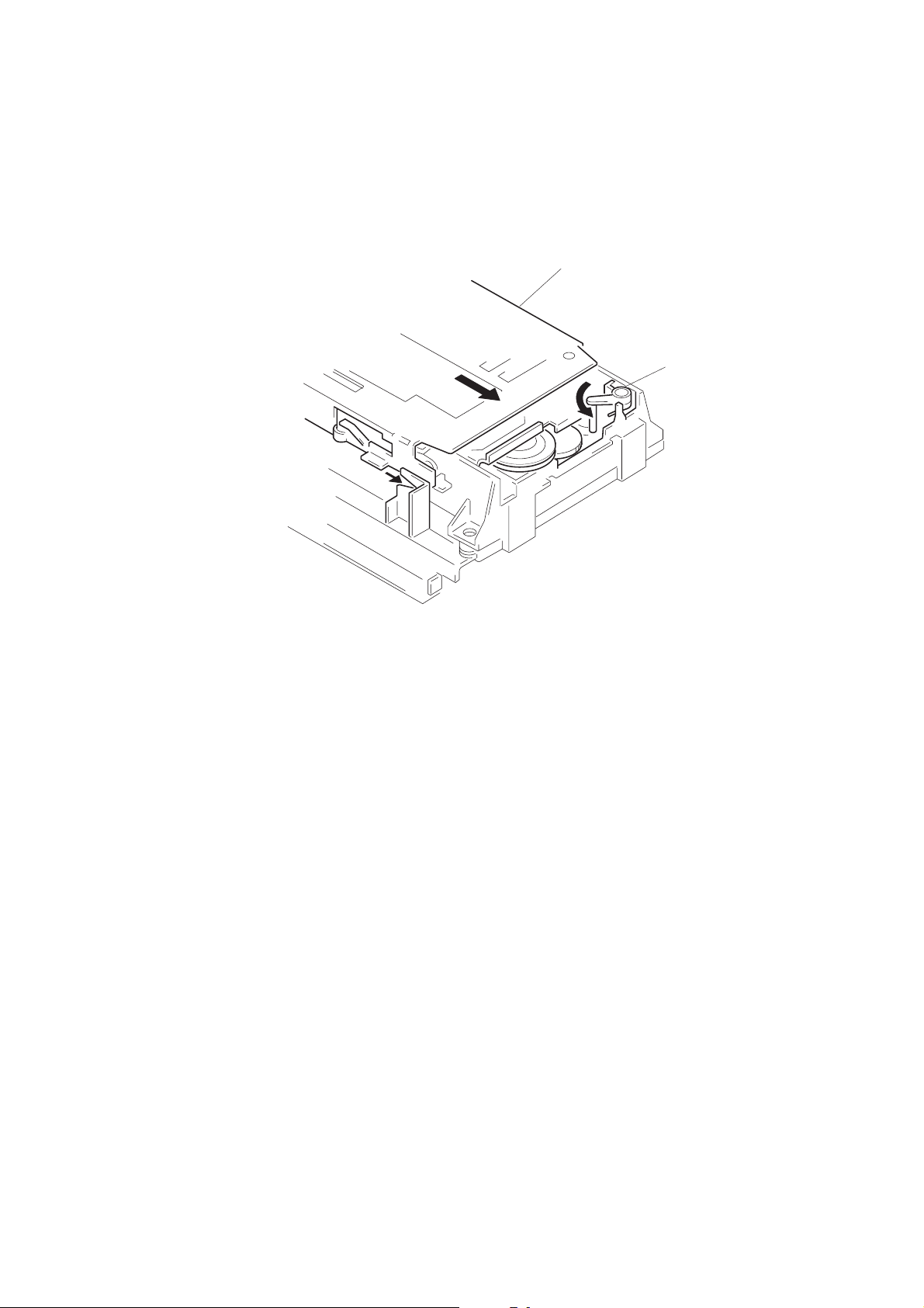
DISC TRAY
4
two claws
3
flat wire (8 core)
2
Pull the disc tray.
5
Remove the disc tray.
flat wire
claw
A
claw
B
Note: When mounting the disc tray, route a flat
cable through claw
in the figure.
1
Rotate the cam to direction
of the arrow.
A
and B as shown
MD MECHANISM
4
two screws
×
18)
(B2.6
5
two
collars
7
MD mechanism
5
two collars
4
two screws
(B2.6
×
18)
B
2
connector (CN251)
3
flat wire (30 core)
(CN202)
3
flat wire (18 core)
(CN221)
6
1
Turn the lever (SLM) toward
direction
(M) assembly toward direction
screw (BTT2.6 × 4)
A
, and slide the slider
A
B
Slider (M) ass’y
lever (SLM)
.
– 10 –

INSTALLATION DISC TRAY
Note: When mounting the disc tray, the collars
A
and B must be engaged in the grooves
respectively .
callar
A
ditch
callar
B
SLIDER (M) ASS’Y
claw
claw
B
C
claw
A
1
Remove a torsion coil
spling from the claw
2
Disengaging the claw B,
raise the lever (SLM) upw ard
to remove.
A
.
A
– 11 –
B
3
Slide the claw C of the slider
(M) assembly up the base
groove in direction
raise the slider (M) assembly
in direction
base groove
B
to remove.
A
, and

INSTALLATION BU CAM ASS’Y BASE UNIT, ROTALY ENCODER
portion A
When mounting the BU cam assembly,
it must be engaged with the rotaly
encorder switch as shown.
When mounting the base unit, insert the
portion A into a groove in the BU cam.
BASE UNIT, LOADING MOTOR ASS’Y
1
screws
×
6)
(BV3
3
belt
4
two screws
(B2.6
×
5)
5
connector
(CN192)
6
loading motor ass’y
2
base unit
– 12 –
1
screw
(BV3
×
6)
INSTALLATION SLIDER (M) ASS’Y
B
2
Slide the slider (M) assembly
toward direction
be locked with the lev er (SLM).
A
B
unit it can
1
Turn fully the lever (SLM)
toward direction
A
.
– 13 –

SECTION 4
n
TEST MODE
Note:
Be sure to connect all wires (including FFC) in the MD
section before applying power or ICs may be damaged.
4-1. OUTLINE
This unit is provided with the following test modes.
1. Check mode for amplifier section
2. Aging mode for CD and MD sections
3. Fluorescent indicator tube and check mode for keys
4. Tracking balance display mode for CD section
5. Check mode for clock function
6. Test mode for MD section
4-2. CHECK MODE FOR AMPLIFIER SECTION
4-2-1. Setting the Check Mode
• Turn ON the power of the unit, and set the check mode by press-
ing the following keys together.
PLAY MODE + π (CD) + GROOVE
When set, the following will be displayed.
EQ - FLT
DBFBAE-0
TUNER
VOL
The function before the check
mode is set is displayed.
(E.g.)
If the function before the check
mode is set is CD, then “CD”
will be displayed.
Differs according to the destination.
AEP,UK models : AE
German model : AE4
Saudi Arabia, Hong Kong, Singapore,
Malaysia models : EA3
Tourist model : JE
4-2-2. Releasing the Check Mode
1. Press the POWER key.
2. The unit sets into the mode for normal operations.
maximum indicatio
4-2-3. Operating the Check Mode
* When the following keys ar e pressed in the check mode state (Re-
fer to Table 4-1.), the switching state of the DBFB, VOLUME,
EQUALIZER functions and VIDEO/GAME functions can be
checked.
Table 4-1
Key Function Display
DBFB ON/OFF switching of the DBFB DBFB-1/
function DBFB-0
DISC 1 Equalizer minimum EQ-MIN
DISC 2 Equalizer flat EQ-FLT
DISC 3 Equalizer maximum EQ-MAX
rREC Volume center
VOLUME
VOLUME
FUNCTION
Volume maximum
Volume minimum
VIDEO/GAME function on VIDEO/GAME
switching
VOL indicator
center position
VOL indicator
maximum position
VOL indicator
minimum position
4-3. AGING MODE FOR CD AND MD SECTIONS
4-3-1. Setting the Aging Mode
1. Load the mini disc (recordable disc) into the MD slot and three
discs onto the CD tray.
2. Turn OFF the power of the unit, and set the aging mode by pressing the following keys together.
DISPLAY + ∏(MD) + GROOVE
4-3-2. Releasing the Aging Mode
1. Press the POWER key.
2. The unit sets into the mode for normal operations.
4-3-3. Operating the Aging Mode
1. When this mode is set, synchro dubbing onto the mini disc is
started, and each time a cycle ends, the cycle number is displayed. When the mini disc has recorded 40 songs on its 30
second track, it erases all the songs.
2. During the aging mode, the VOL display blinks.
– 14 –

3. If errors occur during or after aging, the error messages in the
following table will be displayed.
Table 4-2.
Error Message Contents
MD A-Erase NG Cannot all-erase MD.
MD R-Pause NG Cannot record-pause MD.
MD D-Input NG Cannot lock MD digital in.
Cannot playback last MD song.
MD Play NG (The played back track is not the last
track (access error)).
MD Section
MD TOC NG
MD No Disc NG
CD Focus NG CD focus NG
CD GFS NG CD GFS (Garde frame sync) NG.
CD TOC NG 16 seconds after reading CD TOC.
CD SEARCH NG 16 seconds after CD search.
CD SERVO OK servo system error. May be displayed
CD Section
Refer to NOTE 1.
Note 1:
MD TOC are abnormal.
(The total track is abnormal.)
Cannot read MD TOC.
(Disc error)
Not an error message indicating
during STOP.
Sound jumps lasting more than 1
second during play back.
CD1*99 1m23s
4-4. FLUORESCENT INDICATOR TUBE AND
CHECK MODE FOR KEYS
4-4-1. Setting the Check Mode
• Turn OFF the power of the unit, and set the check mode by press-
ing the following keys together.
§ (MD) + π (MD) + GROOVE
When set, the fluorescent indicator tube and all LEDs will light
up.
4-4-2. Releasing the Check Mode
• Press the POWER key during the check mode for the fluores-
cent indicator tube, or press any key during the check mode for
each key when the display shows “KEY = OK”. The unit sets into
the mode for normal operations.
4-4-3. Operating the Check Mode
• Each time the ENTER/YES key is pressed in the check mode for
the fluorescent indicator tube, the display changes in three ways.
The LED lighting pattern can be changed by rotating the MUL TI
JOG dial.
• Check Mode of Keys
Press the EDIT/NO key to set this mode.
When set, the following will be displayed.
KEY=0JOG=0
The display counts up each time a key is pressed.
(It will not count up when a key already pressed once is pressed
again.) The order of pressing the key and the count up are not
related.)
Point at which sound
jumps occurred.
track number
*
is displayed at the point the
sound jump occurred.
- is displayed normally.
disc number
When a key is pressed.
When all the keys are pressed,
this will be displayed.
(There are altogether 33 keys.)
When a key is pressed during
this display, this check mode
will end.)
KEY
KEY
KEY
=
0JOG=0
=
=
O
1
K
JOG=0
JOG=0
– 15 –

When the MUTLI JOG dial and V OLUME contr ol dial are rotated,
the JOG count display will count up or down accordingly.
(E.g.)
JOG =
This value will be as follows (JOG
count display).
(When the JOG dial is rotated right.)
0 1 2 99 1
Note: To end this mode, KEY=OK must be displayed.
4-5. TRACKING BALANCE DISPLAY MODE FOR
CD SECTION
4-5-1. Setting and Operating the Tracking Balance Indi-
cation Mode
1. Turn ON the power of the unit, and press the [FUNCTION] k ey
to set the CD mode.
(This mode cannot be set if the function is not CD.)
2. Set this mode by pressing the π(CD) + DISPLAY keys together.
3. When set, the following will be displayed.
CD .TR BAL 3.2
4-6. CHECK MODE FOR CLOCK FUNCTION
4-6-1. Setting and Operating the Check Mode
1. Turn OFF the power of the unit.
2. Set this mode by pressing the π (MD) + DISPLAY keys
together.
3. When set, the clock display will be highlighted.
Note: In this mode, the clock display is highlighted only for a short
time. If necessary, press the π (MD) + DISPLAY keys
together again.
(This mode is automatically released.)
VOL
Note:In this mode, the display is lit only for a short time. If neces-
sary, press the πCD + DISPLAY keys together again.
(This mode is automatically released.)
– 16 –

4-7. TEST MODE FOR MD SECTION
4-7-1. Setting the Test Mode
• Turn OFF the power of the unit, and set the test mode by pressing
the following keys together.
FUNCTION + PRESET EQ + GROOVE
When set, the following will be displayed.
MTBU
EMP
4-7-2. Replase the Test Mode
1. Press the REPEAT key.
2. The set thus becomes available for normal operation.
4-7-3. Basic Operation of the Test Mode
• All operations are performed using the MULTI JOG dial,
ENTER/YES key, and EDIT/NO key.
• The functions of these keys are as follows.
Key Contents
MULTI JOG dial Changes parameters and models.
ENTER/YES key
EDIT/NO Key
4-7-4. Selecting the Test Mode
Eight test modes are selectied by turning the MULTI JOG dial.
Display Contents
TEMP ADJUST
LDPWR ADJUST Laser power adjustment
EFBAL ADJUST Traverse (E-F balance) adjustment
FBIAS ADJUST Focus bias adjustment
FBIAS CHECK Focus bias check
CPLAY MODE Continuous playback mode
CREC MODE Continuous reading mode
EEP MODE Non-volatile memory mode (*1)
• For detailed description of each adjustment mode, refer to sec-
tion 5. Electrical Adjustments.
• If a different adjustment mode has been selected by mistake,
press the EDIT/NO key to exit from it.
*1: The EEP MODE is not used in servicing. This mode reads and
writes the contents of the non-volatile memory. If set accidentally, press the EDIT/NO key immediately to exit it.
Proceeds onto the next step.
Finalizes input.
Returns to previous step.
Stops operation.
Tes t
de
AD JUMoST
Table 4-3.
Table 4-4.
Temperature compensation offset
adjustment
4-7-5. Operating the Continuous Playback Mode
1. Entering the continuous playback mode
1) Set the disk in the unit (either MO or CD).
2) Turning the MUL TI JOG dial and display “CPLAY MODE”.
3) Press the ENTER/YES key to change the display “CPLAY
IN” .
4) When access cpmpletes, the display changes to
“C1 = AD = ”.
Note: The “ ” displayed are arbitrary numbers.
2. Changing the parts to be played-back
1) Press the ENTER/YES key during continuous playback to
change the display to “CPLAY MID”, “CPLAY OUT”.
When pressed another time, the parts to be played-back can
be changed.
2) When access completes, the display changes to
“C1 = AD = ”.
Note: The “ ” display are arbitrary numbers.
3. Ending the continuous playback mode
1) Press the EDIT/NO key. The display will change to “CPLA Y
MODE”.
2) Press the §(MD) key and remove the disc.
Notes:
1. The playback start addresses for IN, MID, and OUT are as
follows.
IN: 40h cluster
MID: 300h cluster
OUT: 700h cluster
2. The EDIT/NO KEY can be used to stop playing any time.
4-7-6. Operating the Continuous Recording Mode
1. Entering the continuous recording mode
1) Set the MO disc in the unit.
2) Turning the MULTI JOG dial and display “CREC MODE”.
3) Press the ENTER/YES key to change the display to “CREC
IN”.
4) When access completes, the display changes to “CREC
( )” and REC lights up.
Note: The “ ” displayed are arbitrary humbers.
2. Changing the parts to recorded
1) When the ENTER/YES key is pressed during continuous
recording, the display changes to “CREC MID”, “CREC
OUT” and REC goes off. When pressed another time, the
parts to be recorded can be changed.
2) When access completes, the display changes to “CREC
( )” and REC lights up.
Note: The “ ” displayed are arbitrary numbers.
3. Ending the continuous recording mode
1) Press the EDIT/NO key . The display will change to “CREC
MODE” and REC goes off.
2) Press the §(MD) key and remove the disc.
Notes:
1. The recording start address for IN, MID, and OUT are as
follows.
IN : 40h cluster
MID : 300h cluster
OUT: 700h cluster
– 17 –
2. The EDIT/NO key can be used to stop recording anytime.
3. During the test mode, the erasing-protection tab will not be
detected. Therefore be carefull not to set the continuous recording mode when a disc not be erased is set in the unit.
4. Do not perform continuous recording for long periods of
time above 5 minutes.
5. During continuous recording, be carefull not to apply vibration.
4-7-7. Function of other keys
4-7-8. Test Mode Displays
• Each time the DISPLA Y ke y pressed, the display changes in the
following order.
MODE
display
Error rate
display
Address
display
table 4-5.
CentensKey
Sets continuous playback when pressed in the
STOP state. (servo all on)
·(MD)
When pressed during continuous playback, the
tracking and sled servo turns off.
When pressed during tracking and sled servo
turned off, the turns on.
π(MD)
)
0
r REC
TIME
CONTROL
PLAY
MODE
DISPLAY
§(MD)
Stop continuous playback and continuous recording. (servo all off)
The sled moves to the outer circumference only
when this is pressed.
The sled moves to the inner circumference only
when this is pressed.
Turns recording on/off w hen pressed during continuous playback.
Switches between the pit and groove modes when
pressed.
Switches between the CLV-S (pull-in mode) and
CLV-A (playing servo) modes when pressed.
(Switches the spindle servo mode.)
Switches the display when pressed.
Returns to previous step. Stops operatios.
Disc eject
Note: The erasing-protection tab in not detected during the test
mode. Recording will start regardless of the position of the
erasing-protection tab when the r REC key is pressed.
1. MODE display
Display “TEMP ADJUST”, “CPLAY MODE”, etc.
2. Error rate display
Error rates are displayed as follows.
C1 = AD =
C1 = : Indicates C1 error
AD = : Indicates ADER
3. Address display
Address are displayed as follows.
h = s = (MO pit and CD)
h = s = (MO groove)
h = : Header address
s = : SUB Q address
a = : ADIP address
Note: “—” is display when the address cannot be read.
– 18 –

4-7-9. Meanings of Other Displays
Table 4-6.
Display Contents
Light Off Blinking
During continuous
(
REC
SYNC CLV lock state CLV unlock state
TRACK Pit mode Groove mode
DISC
LEVEL-
SYNC
PROGRAM
SHUFFLE
playback
(servo all on)
Tracking and Tracking and
P
sled servo off sled servo on
Recording mode Recording mode
on off
High reflection Low reflection
rate disc rate disc
Spindle servo Spindle servo
CLV-S (pull-in CLV-A (playing
mode) mode)
ABCD adjustment
Completed
Focus auto gain Focus auto gain
and tracking successful,
auto gain tracking auto
successful gain failed
Stop state
(servo all off)
not adjustment
4-7-10. Precautions for Use of Test Mode
1. As loading related operations will be performed regardless of
the test mode operations being performed, be sure to check that
the disc is stopped before setting and removing it.
Even if the §(MD) key is pressed while the disc is rotating
during continuous playback, continuous recording, etc., the disc
will not stop rotating.
Therefore, it will be ejected while rotating.
Always press the EDIT/NO key first before pressing the
§(MD) key.
2. The erasing-protection tab is not detected in the test mode. Therefore, when modes which output the recording laser power such
as continuous recording mode and traverse adjustment mode,
etc. are set, the recorded contents will be erased regardless of
the position of the tab. When using a disc that is not to be erased
in the test mode, be careful not to enter the continuous recording mode and traverse adjustment mode.
– 19 –

SECTION 5
ELECTRICAL ADJUSTMENTS
Note:
Be sure to connect all wires (including FFC) in the MD
section before applying power or ICs may be damaged.
MD SECTION
5-1. PRECAUTIONS FOR CHECKING LASER DI-
ODE EMISSION
To check the emission of the laser diode during adjustments,
never view directly from the top as this may lose your eyesight.
5-2. PRECAUTIONS FOR USE OF OPTICAL PICK-
UP (KMS-210A)
As the laser diode in the optical pick-up is easily damaged by
static electricity, solder the laser tap of the fle xible board when
using it.
Before disconnecting the connector, desolder first. Before connecting the connector, be careful not to remove the solder.
Also tale adequate measures to prevent damage by static electricity. Handle the fle xible board with care as it breaks easily.
Laser tap
Optical pick-up flexible board
5-3. PRECAUTIONS FOR ADJUSTMENTS
1) When replacing the following parts, perform the adjustments
and checks with ® in the order shown in the following table.
Optical
Pick-up
1. Temperature
compensation
offset adjustment
2. Laser power
adjustment
3. Traverse
adjustment
4. Focus bias
adjustment
5. Error rate check
2) Set the test mode when performing adjustments.
After completing the adjustments, exit the test mode.
3) Perform the adjustments in the order shown.
4) Use the following tools and measuring devices.
• Test disc (CD) TDYS-1 (Parts No. 4-963-646-01)
• Laser power meter LPM-8001 (Parts No. J-2501-046-A)
• Oscilloscope
• Digital voltmeter
• Thermometer
5) When observing several signals on the oscilloscope, etc., make
sure that VC and GND do not connect inside the oscilloscope.
(VC and GND will become short-circuited)
IC171 D101 IC101, IC121, IC191
× ®® ®
® ×× ®
®®× ®
®®× ®
®®× ®
BD (MD) board
5-4. Creating MO Continuously Recorded Disc
* This disc is used in focus bias adjustment and error rate check.
The following describes how to create a MO continuous recording disc.
1. Set the test mode.
2. Insert a MO disc (blank disc) commercially available.
3. Turning the MULTI JOG dial and display “CREC MODE”.
4. Press the ENTER/YES key and display “CREC IN”.
5. Press the ENTER/YES key again to display “CREC MID”.
“CREC (0300)” is displayed for a moment and recording starts.
6. Complete recording within 5 minutes.
7. Press the EDIT/NO key and stop recording.
8. Press the § (MD) key and remove the MO disc.
The above has been how to create a continuous recording data for
the focus bias adjustment and error rate check.
Note:
• Be careful not to apply vibration during continuous recording.
– 20 –
5-5. TEMPERATURE COMPENSATION OFFSET
r
+
–
BD (MD) board
TP (I+5V)
TP (IOP)
digital voltmeter
ADJUSTMENT
Save the temperature data at that time in the non-volatile memory
as 25°C reference data.
Note:
1. Usually, do not perform this adjustment.
2. Perform this adjustment in an ambient temperature of 22°C to
28°C. Perform it immediately after the power is turned on when
the internal temperature of the unit is the same as the ambient
temperature.
3. When D101 has been replaced, perform this adjustment after
the temperature of this part has become the ambient temperature.
Adjusting Method:
1. Turning the MULTI JOG dial and display “TEMP ADJUST”.
2. Press the ENTER/YES key and select the “TEMP ADJUST”
mode.
3. “TEMP = ” and the current temperature a data will be displayed.
4. To save the data, press the ENTER/YES key.
When not saving the data, press the EDIT/NO key.
5. When the ENTER/YES key is pressed, “TEMP= SAVE”
will be displayed for some time, followed by “TEMP ADJUST”.
When the EDIT/NO key is pressed, “TEMP ADJUST” will be
displayed.
Specifications:
The temperature should be within “E0-EF”, “F0-FF”, “00-0F”,
“10-1F” and “20-2F”.
5-6. LASER POWER ADJUSTMENT
Connection:
laser
power mete
Optical pick-up
objective lens
Adjusting Method:
1. Set the laser power meter on the objective lens of the optical
pick-up. (When it cannot be set properly, press the 0 key or
) key and move the optical pick-up.)
Connect the digital voltmeter to TP (IOP) and TP (I+5V).
2. Turning the MULTI JOG dial and display “LDPWR ADJUST”.
(Laser power: For adjustment)
3. Press the ENTER/YES key twice and display “LD $ 4B
=3.5mW”.
4. Adjust RV102 of the BD (MD) board so that the reading of the
laser power meter becomes 3.4 mW.
5. Press the ENTER/YES key and display “LD $96=7.0 mW”.
(Laser power: MO writing)
6. Check that the laser power meter and digital voltmeter readings
satisfy the specified value.
+0.1
–0
Specification:
Laser power meter reading : 7.0 ± 0.3 mW
Digital voltmeter reading : Optical pick-up displayed value ±10%
(Optical pick-up label)
KMS210A
27X40
B0825
lOP=82.5 mA in this case
lOP (mA) = Digital voltmeter reading (mV)/1 (
Ω
)
7. Press the ENTER/YES key and display “LD $ 0F=0.7 mW”.
(Laser power: MO reading)
8. Check that the laser power meter at this time satisfied the specified value.
Specification:
Laser power meter reading: 0.70 ± 0.1 mW
9. Press the EDIT/NO key and display “LDPWR ADJUST”, and
stop laser emission.
(The EDIT/NO key is effective at all times to stop the laser
emission.)
– 21 –

5-7. TRAVERSE (E-F BALANCE) ADJUSTMENT
Note 1) Data will be erased during MO reading if a recorded
disc is used in this adjustment.
Note 2) If the traverse waveform is not clear, connect the os-
cilloscope as shown in the following figure so that it
can be seen more clearly.
330 k
TP (TEO)
TP (VC)
oscilloscope
Ω
+
–
10 pF
11. Turning the MULTI JOG dial until the waveforms of the oscilloscope moves closer to the specified value.
In this adjustment, waveform varies at intervals of approx. 3%.
Adjust the waveform so that the specified value is satisfied as
much as possible.
(Traverse W a v ef orm)
A
VC
B
specification: A=B
Connection:
oscilloscope
BD (MD) board
TP (TEO)
TP (VC)
+
–
Adjusting Method:
1. Connect an oscilloscope to TP (TEO) and TP (VC) of the BD
(MD) board.
2. Load a MO disc (any available on the market).
3. Press the 0 key or ) key and move the optical pick-up
outside the pit.
4. Turning the MULTI JOG dial and display “EFBAL ADJUST”.
5. Press the ENTER/YES key and display “EFBAL MO-W”.
(Laser power WRITE power/Focus servo ON/tracking servo
OFF/spindle (S) servo ON)
6. Adjust RV101 of the BD (MD) board so that the waveform of
the oscilloscope becomes the specified value.
(MO groove write power traverse adjustment)
(T r averse W av ef orm)
A
VC
specification: A=B
B
7. Press the ENTER/YES key and display “EFB=$ MO-R”.
(Laser power: MO reading)
8. Turning the MULTI JOG dial so that waveforms of the oscilloscope becomes the specified value.
(When the MULTI JOG dial is turned, the of “EFB= ”
changes and the waveform changes.) in this adjustment, waveform varies at intervals of approx. 3%. Adjust the waveform so
that the specified value is satisfied as much as possible.
(MO groove read power traverse adjustment)
(T r averse W av ef orm)
A
VC
B
12. Press the ENTER/YES key, display “EFB=$ SAVE” for a
moment and save the adjustment results in the non-volatile
memory.
Next “EFBAL CD” is displayed. The disc stops rotating automatically.
13. Press the § (MD) key and remove the MO disc.
14. Load the test disc TDYS-1.
15. Press the ENTER/YES key and display “EFB=$ CD”. Servo
is imposed automatically.
16. Turning the MULTI JOG dial so that the waveforms of the oscilloscope moves closer to the specified value.
In this adjustment, waveform varies at inter vals of appro x. 3%.
Adjust the waveform so that the specified value is satisfied as
much as possible.
(Traverse W a v ef orm)
A
VC
B
specification: A=B
17. Press the ENTER/YES key, display “EFB=$ SAVE” for a
moment and save the adjustment results in the non-volatile
memory.
Next “EFBAL ADJUST” is displayed.
18. Press the § (MD) key and remove the test disc TDYS-1.
specification: A=B
9. Press the ENTER/YES key, display “EFB=$ SAVE” for a
moment and save the adjustment results in the non-volatile
memory.
Next “EFBAL MO-P” is displayed.
10. Press the ENTER/YES key and display “EFB=$ MO-P”.
The optical pick-up moves to the pit area automatically and servo
is imposed.
– 22 –

5-8. FOCUS BIAS ADJUSTMENT
Adjusting Method:
1. Load a continuously recorded disc (Refer to “5-4. Creating MO
Continuously Recorded Disc”.)
2. Turning the MULTI JOG dial and display “CPLAY MODE”.
3. Press the ENTER/YES key twice and display “CPLAY MID”.
4. Press the EDIT/NO key when “C1= AD= ” is
displayed.
5. Turning the MULTI JOG dial and display “FBIAS ADJUST”.
6. Press the ENTER/YES key and display “ / a= ”.
The first four digits indicate the C1 error rate, the two digits
after [/] indicate ADER, and the 2 digits after [a=] indicate the
focus bias value.
7. Turning the MULTI JOG dial in the clockwise direction and
find the focus bias value at which the C1 error rate becomes
220.
8. Press the ENTER/YES key and display “ / b= ”.
9. Turning the MULTI JOG dial in the clockwise direction and
find the focus bias value at which the C1 error rate becomes
220.
10. Press the ENTER/YES key and display “ / c= ”.
11. Check that the C1 error rate is below 50 and ADER is 00.
Then press the ENTER/YES key.
12. If the “( )” in “ - - ( )” is above 20, press the
ENTER/YES key.
If below 20, press the EDIT/NO key and repeat the adjustment
from step 2 again.
13. Press the EDIT/NO key and press the § (MD) key to remov e
the continuously recorded disc.
Note 1: The relation between the C1 error and focus bias is as shown
in the following figure. Find points a and b in the following
figure using the above adjustment. The focal point position
c is automatically calculated from points a and b.
Note 2: As the C1 error rate changes, perform the adjustment using
the average vale.
C1 error
220
Focus bias value
bcb
(F. BIAS)
5-9. ERROR RATE CHECK
5-9-1. CD Error Rate Check
Checking Method:
1. Load a test disc TDYS-1.
2. Turning the MULTI JOG dial and display “CPLAY MODE”.
3. Press the ENTER/YES key twice and display “CPLAY MID”.
4. “C1= AD= – –” is displayed.
5. Check that the C1 error is below 20.
6. Press the EDIT/NO key, stop playback, press the § (MD)
key, and remove the test disc.
5-9-2. MO Error Rate Check
Checking Method:
1. Load a continuously recorded disc (Refer to “5-4. Creating MO
Continuously Recorded Disc”.)
2. Turning the MULTI JOG dial and display “CPLAY MODE”.
3. Press the ENTER/YES key twice and display “CPLAY MID”.
4. “C1= AD= ” is displayed.
5. If the C1 error rate is below 50, check that ADER is 00.
6. Press the EDIT/NO key, stop playback, press the § (MD)
key, and remove the continuously recorded disc.
5-10. FOCUS BIAS CHECK
Change the focus bias and check the focus tolerance amount.
Checking Method:
1. Load a continuously recorded disc (Refer to “5-4. Creating MO
Continuously Recorded Disc”.)
2. Turning the MULTI JOG dial and display “CPLAY MODE”.
3. Press the ENTER/YES key twice and display “CPLAY MID”.
4. Press the EDIT/NO key when “C1= AD= ” is
displayed.
5. Turning the MULTI JOG dial and display “FBIAS CHECK”.
6. Press the ENTER/YES key and display “ / c= ”.
The first four digits indicate the C1 error rate, the two digits
after [/] indicate ADER, and the 2 digits after [c=] indicate the
focus bias value.
Check that the C1 error is below 50 and ADER is 00.
7. Press the ENTER/YES key and display “ / b= ”.
Check that the C1 error is not below 220 and ADER is not above
00 every time.
8. Press the ENTER/YES key and display “ / a= ”.
Check that the C1 error is not below 220 and ADER is not above
00 every time.
9. Press the EDIT/NO key, next press the § (MD) key, and remove the continuously recorded disc.
Note 1: If the C1 error and ADER are above 00 at points a or b, the
focus bias adjustment may not have been carried out properly. Adjust perform the beginning again.
– 23 –

5-11. ADJUSTING POINTS AND CONNECTING POINTS
[BD (MD) BOARD] (Side A)
D101
[BD (MD) BOARD] (Side B)
IC171
(IOP)
RV101
(I+5V)
RV102
IC191
IC101
(VC)
(TEO)
IC121
– 24 –
TUNER SECTION
set
AM RF signal
generator
+
–
level meter
SPEAKER terminal
AM ANTENNA terminal (TM1)
30% amplitude
modulation by
400 Hz signal
0 dB=1µV
Precaution in Repairing
Note : As a front-end (FE1) is difficult to repair if faulty, replace it
with new one.
• Abbreviation
EA : Saudi Arabia
MY : Malaysia
SP : Singapore
HK : Hong Kong
AM Tuned Level Adjustment
Note : FM Tuned Level Adjustment Should be performed after this
AM Tuned Level Adjustment.
Setting :
Band : AM or MW
loop antenna A
AM RF signal
generator
loop antenna B
set
SW OSC Voltage Adjustment (EA, MY, SP, HK model)
Setting :
Band : SW
Procedure :
1. Connect digital voltmeter to diode D1 center lead and ground.
2. Adjust for a following value reading on digital voltmeter.
Adjustment Reading on
part digital voltmeter
SW
Set frequency
5.95 MHz T2 1.2 Vdc
17.9 MHz CV2 8.5 Vdc
Adjustment Location : TCB board (see page 26)
SW Tracking Adjustment (EA, MY, SP, HK model)
Setting :
Band : SW
30% amplitude
modulation by
400 Hz signal
Carrier frequency: 999 kHz (at 9 kHz step)
1,050 kHz (at 10 kHz step)
60 cm
AM ANTENNA
terminal (TM1)
Procedure :
1. Set loop antenna A so that the loop antenna B input level becomes 50 dBµ (0.32 mV)
2. Tune the set to 999 kHz (at 9 kHz step) or 1,050 kHz (at 10 kHz
step).
3. Adjust RV41 so that the TUNED indicator goes on.
Adjustment Location : TCB board (see page 26)
FM Tuned Level Adjustment
Note : This adjustment should be performed after the AM Tuned
Level Adjustment.
Setting :
Band : FM
FM RF stereo signal
generator
Carrier frequency : 98 MHz
Modulation : 1 kHz, 75 kHz deviation (100%)
Output level : 25 dB
FM ANTENNA terminal (TM1)
75 Ω coaxial
set
µ
(0.018 mV)
Procedure :
Adjust for maximum reading on level meter.
Adjustment
part
SW
Set frequency
7 MHz T1
17 MHz CV1
• Repeat the procedures is each adjustment several times, and the
OSC voltage and tracking adjustment should be finally done by
the trimmer capacitors.
Adjustment Location : TCB board (see page 26)
Procedure :
1. Tune the set to 98 MHz
2. Adjust RV42 so that the TUNED indicator goes on.
Adjustment Location : TCB board (see page 26)
– 25 –
Adjustment Location
t
+
–
BD (CD) board
TP (RF)
TP (VC)
oscilloscope
(DC range)
+
–
BD (CD) board
TP (FEO)
TP (VC)
oscilloscope
[TCB BOARD] – Component side –
CV1: SW Tracking Adjustmnet
RV41:
AM Tuned Level
Adjustment
CV2:
SW OSC voltage
Adjustment
T2:
SW OSC voltage
Adjustment
RV42:
FM Tuned Level
Adjustment
T1: SW Tracking Adjustmen
D1
FE1
CD SECTION
Note :
1. Use YEDS-18 disc (3-702-101-01) unless otherwise indicated.
2. Use the oscilloscope with more than 10 MΩ impedance.
3. Clean an object lens by an applicator with neutral detergent when
the signal level is low than specified value with the following
checks.
Focus Bias Adjustment
This adjustment is to be done when the optical pick-up is replaced.
Adjustment procedure :
1. Connect oscilloscope to test point TP (VC) and TP (RF) on BD
(CD) board.
2. Turned power switch ON. (Stop mode)
3. Put disc (YEDS-18) in and press the · (CD) key.
4. Adjust RV101 so that the oscilloscope w a veform is as sho wn in
the figure below (eye pattern).
A good eye pattern means that the diamond shape (≈) in the
center of the waveform can be clearly distinguished.
• RF signal reference waveform (eye pattern)
VOLT/DIV: 200 mV
TIME/DIV: 500 ns
1.3
±
0.3Vp-p
When observing the eye pattern, set the oscilloscope for AC
range and raise vertical sensitivity.
S-Curve Check
Procedure :
1. Connect oscilloscope to test point TP (VC) and TP (FEO) on
BD (CD) board.
2. Connect between test point TP (FOK) and GND by lead wire.
3. Turned Power switch on.
4. Put disc (YEDS-18) in and turned Power switch on again and
actuate the focus search. (actuate the focus search when disc
table is moving in and out.)
– 26 –

5. Check the oscilloscope waveform (S-curve) is symmetrical be-
A
B
level: 300
±
100 mVp-p
IC104
IC102
IC101
FEI
TEI
FOK
RF
RV101
RV103
TEO
FEO
VC
RV102
tween A and B. And conf irm peak to peak le v el within 2.4 ± 0.7
Vp-p.
Traverse waveform
S-curve wavef orm
symmetry
A
B
within 2.4
±
0.7 Vp-p
6. After check, remove the lead wire connected in step 2.
Note : • Try to measure several times to make sure that the ratio
of A : B or B : A is more than 10 : 7.
• Take sweep time as long as possible and light up the
brightness to obtain best waveform.
RF Level Check
oscilloscope
BD (CD) board
TP (RF)
TP (VC)
+
–
Procedure :
1. Connect oscilloscope to test point TP (VC) and TP (RF) on BD
(CD) board.
2. Turned Power switch on.
3. Put disc (YEDS-18) in and press the · (CD) key.
4. Confirm that oscilloscope wavefor m is clear and check RF signal level is correct or not.
Note :
Clear RF signal waveform means that the shape “≈” can be
clearly distinguished at the center of the waveform.
specified level :• —————— × 100 = less than ± 7%
A–B
2 (A+B)
• A+B= 300 ± 100 mVp-p
6. Remove the lead wire connected in step 1.
Focus/Tracking Gain Adjustment (RV102, RV103)
This gain has a margin, so ev en if it is slightly off. There is no problem.
Therefore, do not perform, this adjustment.
Please note that it should be fixed to mechanical center position
when you moved and do not know original position.
Adjustment Location :
[BD (CD) BOARD] – Side B –
RF signal waveform
VOLT/DIV: 200 mV
TIME/DIV: 500 ns
level: 1.3
±
0.3Vp-p
E-F Balance (Traverse) Check
oscilloscope
(DC range)
BD (CD) board
TP (TEO)
TP (VC)
+
–
Procedure :
1. Connect the TP (TEI) and TP (VC) with lead wire.
2. Connect oscilloscope to test point TP (VC) and TP (TEO) on
BD (CD) board.
3. Turned Power switch on.
4. Put disc (YEDS-18) in and press the · (CD) key.
5. Confirm that the oscilloscope waveform is symmetrical on the
top and bottom in relation to 0 Vdc, and check this level.
– 27 –

• Circuit Boards Location
PANEL A board
SECTION 6
DIAGRAMS
TCB board
THERMO board
MAIN board
TRANSFORMER board
HEADPHONE board
BD (MD) board
PANEL B board
SENSOR board
POWER board
AMPLIFIER board
MOTOR (TURN) board
CONNECTOR board
DETECTION SW
board
MOTOR board
BD (CD) board
DIGITAL board
RELAY board
MOTOR (SLIDE) board
– 28 –

 Loading...