

Sony HCD-M500AV Service manual
HCD-M500AV
SERVICE MANUAL
Ver 1.1 2001. 07
HCD-M500AV is the tuner, deck, CD and
amplifier section in MHC-M500AV.
Manufactured under license from Dolby
Laboratories Licensing Corporation.
“DOLBY” and the double-D symbol ; and
“PRO LOGIC” are trademarks of Dolby
Laboratories Licensing Corporation.
CD
SECTION
TAPE DECK
SECTION
Model Name Using Similar Mechanism HCD-MC3AV
CD Mechanism Type CDM-46B1
Optical Pick-up Name KSM-213BFN/C2NP
Model Name Using Similar Mechanism NEW
Tape Transport Mechanism Type TCM-230AWR21
US Model
Amplifier section
U.S.A models:
AUDIO POWER SPECIFICATIONS
POWER OUTPUT AND TOTAL HARMONIC DISTORTION:
With 6 Ω loads both channels driven, from 120 – 10,000 Hz; rated 75 W per
channel minimum RMS power, with no more than 10% total harmonic
distortion from 250 mW to rated output.
Front Speaker:
Continuous RMS power output
75 + 75 W
(6 Ω at 1 kHz, 10% THD)
Total harmonic distortion
less than 0.09%
(6 Ω at 1 kHz, 40 W)
Center Speaker:
Continuous RMS power output
35 W
(6 Ω at 1 kHz. 10% THD)
Rear Speaker:
Continuous RMS power output
35 + 35 W
(6 Ω at 1 kHz, 10% THD)
SPECIFICATIONS
Inputs
VIDEO/MD IN (phono jack):
voltage 250 mV/450 mV,
impedance 47 kΩ
DVD
FRONT (phono jacks): voltage 450 mV,
impedance 47 kΩ
REAR (phono jacks): voltage 450 mV,
impedance 47 kΩ
CENTER (phono jacks): voltage 450 mV,
impedance 47 kΩ
WOOFER (phono jacks): voltage 450 mV,
impedance 47 kΩ
Outputs
PHONES (stereo phone jacks):
accepts headphones of 8 Ω or more
FRONT SPEAKER: accepts impedance of 6 to 16 Ω
REAR SPEAKER: accepts impedance of 6 to 16 Ω
CENTER SPEAKER: accepts impedance of 6 Ω
SUPER WOOFER: voltage 1 V, impedance 1 kΩ
— Continued on next page —
9-929-288-12
2001G0200-1
© 2001.7
COMPACT COMPONENT SYSTEM
Sony Corporation
Home Audio Company
Shinagawa Tec Service Manual Production Group
1

CD player section
System Compact disc and digital audio system
Laser Semiconductor laser (λ =780 mm)
Emission duration: continuous
Laser output Max. 44.6 µW*
* This output is the value measured at a
distance of 200 mm from the objective lens
surface on the Optical Pick-up Block with
7 mm aperture.
Frequency response 2 Hz – 20 kHz (± 0.5 dB)
Wavelength 780 – 790 nm
Signal-to-noise ratio More than 90 dB
Dynamic range More than 90 dB
CD OPTICAL DIGITAL OUT
(Square optical connector jack, rear panel)
Wave length 600 nm
Output level –18 dBm
AM tuner section
Tuning range 530 – 1,710 kHz
(with the interval set at 10 kHz)
531 – 1,710 kHz
(with the interval set at 9 kHz)
Antenna AM loop antenna
Antenna terminals External antenna terminal
Intermediate frequency 450 kHz
General
Power requirements 120 V AC, 60 Hz
Power consumption 210 W
Dimensions (w/h/d) Approx. 280 × 373 × 468 mm
Mass Approx. 11.0 kg
Tape player section
Recording system 4-track 2-channel stereo
Frequency response 40 – 13,000 Hz (± 3 dB),
using Sony TYPE I cassette
Tuner section
FM stereo, FM/AM superheterodyne tuner
FM tuner section
Tuning range 87.5 – 108.0 MHz
Antenna FM lead antenna
Antenna terminals 75 Ω unbalanced
Intermediate frequency 10.7 MHz
Supplied accessories: AM loop antenna (1)
Remote commander (1)
Batteries (2)
FM lead antenna (1)
Speaker cords (2)
Center speaker pads (4)
Manual connecting cord (1)
Design and specifications are subject to change without notice.
2
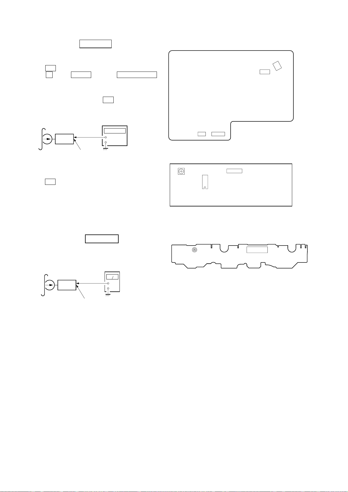
CAUTION
0.15µF
To Exposed Metal
Parts on Set
1.5kΩ
AC
voltmeter
(0.75V)
Earth Ground
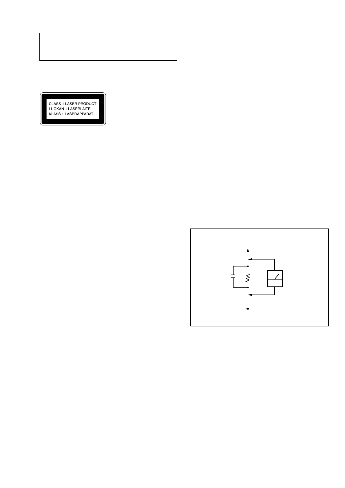
Use of controls or adjustments or performance of procedures
other than those specified herein may result in hazardous radiation
exposure.
This appliance is classified as a CLASS 1 LASER product. The
CLASS 1 LASER PRODUCT MARKING is located on the rear
exterior.
SAFETY CHECK-OUT
(US model only)
After correcting the original service problem, perform the
following safety checks before releasing the set to the customer:
Check the antenna terminals, metal trim, “metallized” knobs, screws,
and all other exposed metal parts for AC leakage. Check leakage as
described below.
LEAKAGE
The AC leakage from any exposed metal part to earth ground and
from all exposed metal parts to any exposed metal part having a
return to chassis, must not exceed 0.5 mA (500 microampers).
Leakage current can be measured by any one of three methods.
Laser component in this product is capable of emitting radiation
exceeding the limit for Class 1.
1. A commercial leakage tester, such as the Simpson 229 or RCA
WT-540A. Follow the manufacturers’ instructions to use these
instruments.
2. A battery-operated AC milliammeter. The Data Precision 245
digital multimeter is suitable for this job.
3. Measuring the voltage drop across a resistor by means of a
VOM or battery-operated AC voltmeter. The “limit” indication
is 0.75 V, so analog meters must have an accurate low-voltage
scale. The Simpson 250 and Sanwa SH-63Trd are examples of
a passive VOM that is suitable. Nearly all battery operated
digital multimeters that have a 2V AC range are suitable. (See
Fig. A)
Fig. A. Using an AC voltmeter to check AC leakage.
SAFETY-RELATED COMPONENT WARNING!!
COMPONENTS IDENTIFIED BY MARK 0 OR DOTTED LINE WITH
MARK 0 ON THE SCHEMATIC DIAGRAMS AND IN THE PARTS
LIST ARE CRITICAL TO SAFE OPERATION. REPLACE THESE
COMPONENTS WITH SONY PARTS WHOSE PART NUMBERS
APPEAR AS SHOWN IN THIS MANUAL OR IN SUPPLEMENTS
PUBLISHED BY SONY.
3

SERVICING NOTES
NOTES ON HANDLING THE OPTICAL PICK-UP
BLOCK OR BASE UNIT
The laser diode in the optical pick-up block may suffer electrostatic
break-down because of the potential difference generated by the
charged electrostatic load, etc. on clothing and the human body.
During repair, pay attention to electrostatic break-down and also
use the procedure in the printed matter which is included in the
repair parts.
The flexible board is easily damaged and should be handled with
care.
TABLE OF CONTENTS
1. GENERAL
Font Panel ··············································································· 5
Rear Panel ·············································································· 6
2. DISASSEMBLY ······························································· 8
3. TEST MODE ··································································· 16
4. MECHANICAL ADJUSTMENTS ···························· 18
NOTES ON LASER DIODE EMISSION CHECK
The laser beam on this model is concentrated so as to be focused on
the disc reflective surface by the objective lens in the optical pickup block. Therefore, when checking the laser diode emission, observe
from more than 30 cm away from the objective lens.
LASER DIODE AND FOCUS SEARCH OPERATION
CHECK
Carry out the “S curve check” in “CD section adjustment” and check
that the S curve waveform is output repeatedly.
Notes on chip component replacement
• Never reuse a disconnected chip component.
• Notice that the minus side of a tantalum capacitor may be damaged
by heat.
Flexible Circuit Board Repairing
• Keep the temperature of the soldering iron around 270 ˚C during
repairing.
• Do not touch the soldering iron on the same conductor of the
circuit board (within 3 times).
• Be careful not to apply force on the conductor when soldering or
unsoldering.
5. ELECTRICAL ADJUSTMENTS
Deck Section ········································································ 21
CD Section ··········································································· 23
6. DIAGRAMS
6-1. Block Diagram – CD Section – ········································ 24
Block Diagram – Main Section – ····································· 25
Block Diagram – Audio Section –···································· 26
6-2. Circuit Boards Location ··················································· 27
6-3. Printed Wiring Board – BD Section – ······························ 28
6-4. Schematic Diagram – BD Section – ································· 29
6-5. Printed Wiring Board – CD Motor Section – ··················· 30
6-6. Schematic Diagram – CD Motor Section – ······················ 31
6-7. Printed Wiring Board – Audio Section – ·························· 32
6-8. Schematic Diagram – Audio Section –····························· 33
6-9. Printed Wiring Board – Main Section – ··························· 34
6-10. Schematic Diagram – Main (1/6) Section – ····················· 35
6-11. Schematic Diagram – Main (2/6) Section – ····················· 36
6-12. Schematic Diagram – Main (3/6) Section – ····················· 37
6-13. Schematic Diagram – Main (4/6) Section – ····················· 38
6-14. Schematic Diagram – Main (5/6) Section – ····················· 39
6-15. Schematic Diagram – Main (6/6) Section – ····················· 40
6-16. Printed Wiring Board – Power Section – ························· 41
6-17. Schematic Diagram – Power Section – ···························· 41
6-18. Printed Wiring Board – Panel Section – ··························· 42
6-19. Schematic Diagram – Panel Section – ····························· 43
6-20. Printed Wiring Board – Front Amp Section – ·················· 44
6-21. Schematic Diagram – Front Amp Section – ····················· 45
6-22. Schematic Diagram – Rear Amp Section – ······················ 46
6-23. Printed Wiring Board – Rear Amp Section – ··················· 47
6-24. Waveforms ········································································ 48
6-25. IC Pin Function Description ············································· 48
6-26. IC Block Diagrams ··························································· 56
7. EXPLODED VIEWS ····················································· 59
8. ELECTRICAL PARTS LIST ····································· 66
4

FRONT PANEL
5
4
3
2
1
el
ek
ej
eh
eg
ef
SECTION 1
GENERAL
678 90 qaqsqd qfqgqh
ql
qj
qk
w;
wa
ws
wd
wf
wg
wh
wj
1 @/1 button
2 STANDBY indicator
3 MEMO INPUT button
4 MEMO SCAN button
5 MEMO SEARCH button
6 TAPE A h button and indicator
7 CD 7 button and indicator
8 TAPE A H button and indicator
9 Display window
0 x (STOP) button
qa TAPE B h button and indicator
qs TUNER/BAND button
qd TAPE B H button and indicator
qf CHECK button
qg CLEAR button
qh DELETE button
qj GROOVE button and indicator
qk FUNCTION button
ql DSP button and indicator
w; DBFB button
wk
wle;eaesed
wa CONTINUE/STEREO/MONO button
ws ENTER button
wd PROGRAM/TUNER MEMORY button
wf SHUFFLE/DIRECTION button
wg + M > button
wh . m – button
wj SELECTOR dial
wk PHONES jack
wl FILE SELECT button
e; VOLUME knob
ea X PAUSE button and indicator
es CD SYNCHRO button
ed z REC button
ef CD PLUS ONE button
eg TIMER SELECT button and indicator
eh CLOCK TIMER SET button
ej DISPLAY button
ek PROLOGIC button and indicator
el DVD5.1CH button and indicator
5
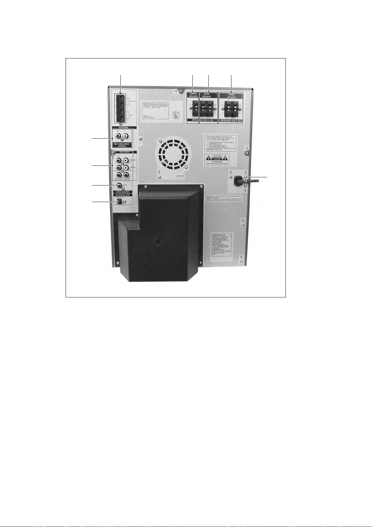
REAR PANEL
5 6 7 8
4
3
9
2
1
1 CD DIGITAL OUT connector
2 SUPER WOOFER jack
3 DVD INPUT jack
4 MD/VIDEO INPUT (AUDIO) jack
5 ANTENNA terminal
6 CENTER SPEAKER terminal
7 REAR SPEAKER terminal
8 FRONT SPEAKER terminal
9 AC power cord
6
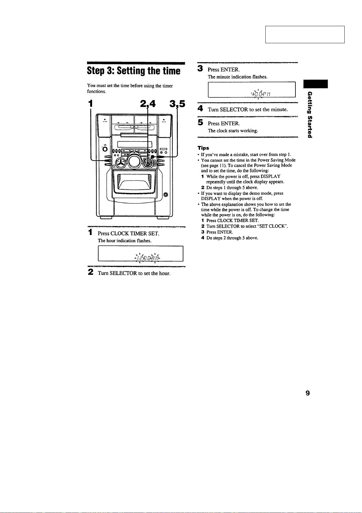
This section is extracted from
instruction manual.
7
SECTION 2
)
DISASSEMBLY
Note : Follow the disassembly procedure in the numerical order given.
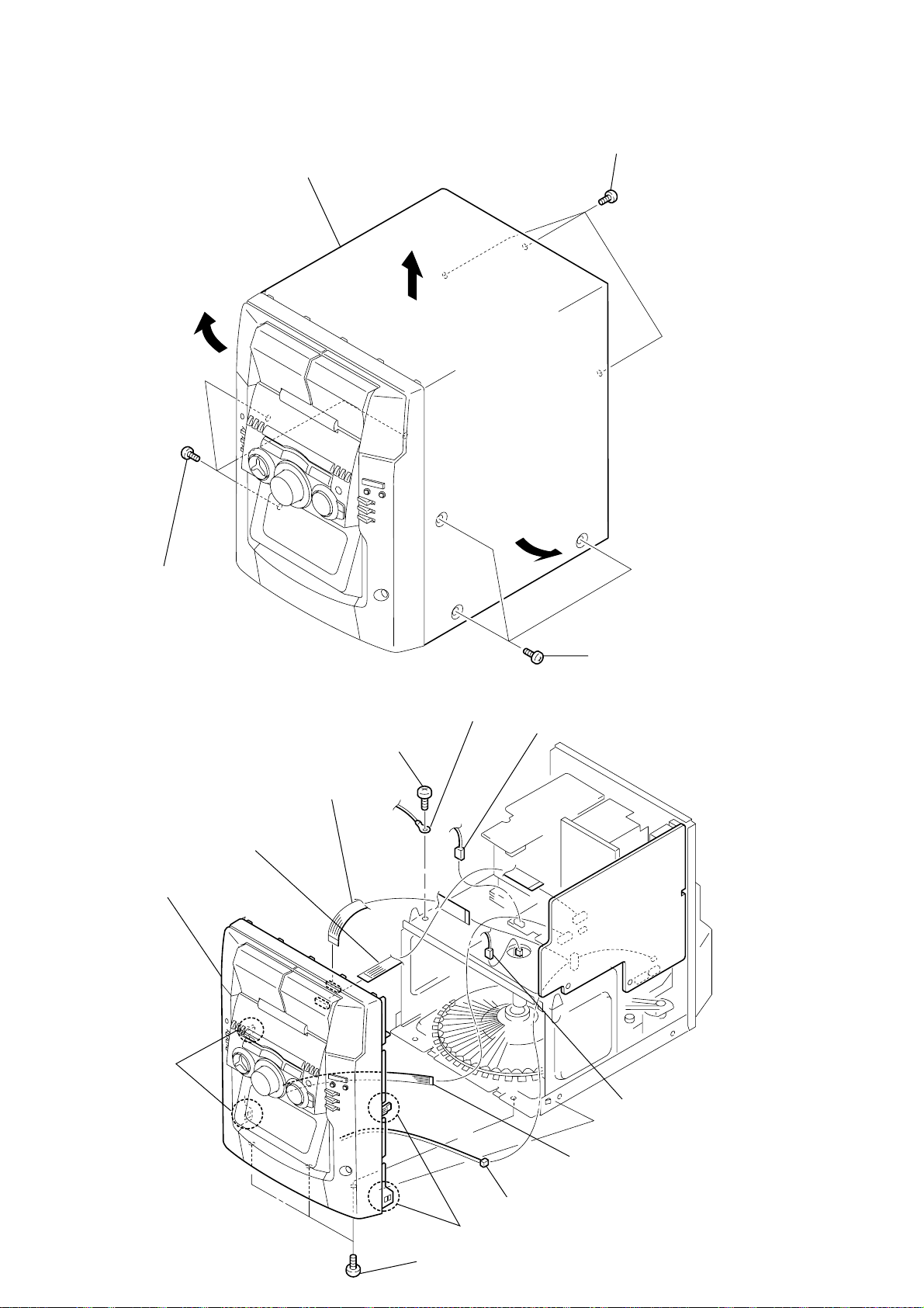
2-1. CASE
3 Case
2 Three screws
(BVTP 3 × 8)
1 Three screws
(CASE3 TP2)
2-2. FRONT PANEL SECTION
2 Wire (flat type)
(15 core)
qa Front panel assy
7 Screws
(BVTT 3 × 8)
1 Wire (flat type)
(17 core)
8 Lug
1 Three screws
(CASE3 TP2)
4 Connector(CN804)
0 Two claws
5 Connector(CN604A
3 Wire (flat type) (10 core)
6 Connector(CN453)
0 Two claws
8
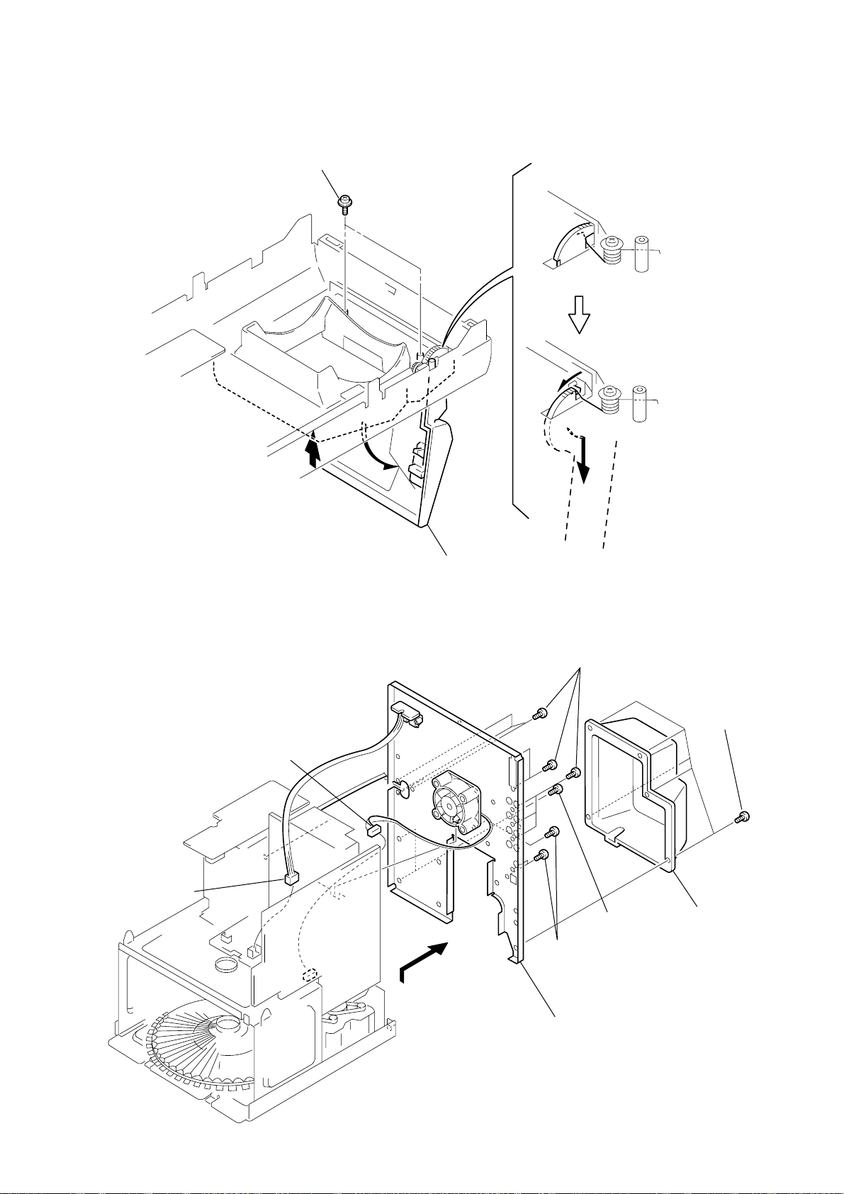
9 Three screws
(BVTP 3 × 8)
2-3. DOOR ASSY
y
)
1 Two screws
(PTPWH 2.6 × 8)
A
3 Remove the door ass
to direction of the
arrow A.
2-4. BACK PANEL
1 Connector
(CN802)
2 Connector(CN751)
2 Open the door assy
7 Eight screws
(BVTP 3 × 8)
6 Two screws
(BVTP 3 × 8)
5 Three screws
(BVTP 3 × 8)
3 Five screws
(BVTP 3 × 8
4 Cover
8 Remove the back panel
to direction of the arrow.
9
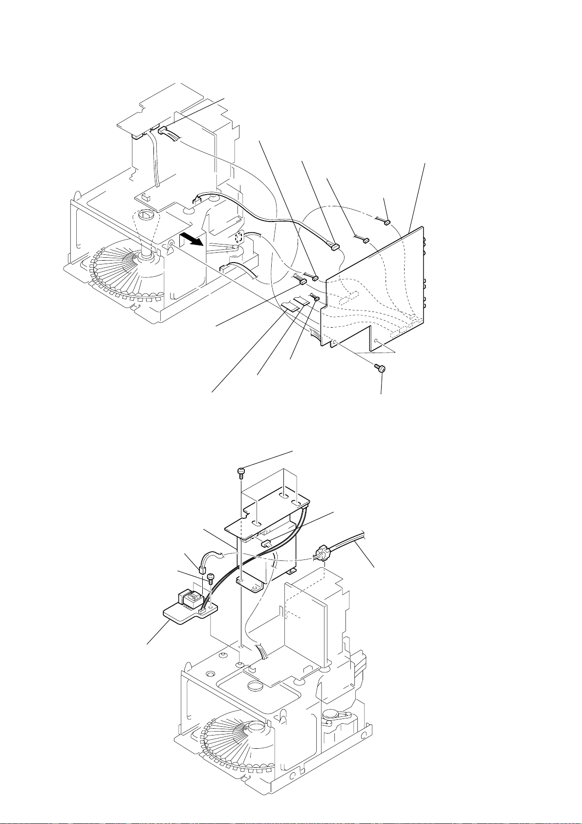
2-5. MAIN BOARD
N
6
d
9 Connector(CN454)
3 Connector(CN902)
1 Wire (flat type) (16 core)
5 Connector(CN454)
4 Connector(CN801B)
8 Connector(CN403)
7 Connector(CN451)
2 Wire (flat type) (9 core)
qa Remove the MAI
board to direction
of the arrow.
6 Connector(CN461)
0 Two screws
(BVTP 3 × 8)
2-6. POWER TRANSFORMER (T991)
7 Power transforme (T991)
3 Connector CN995
4 Two screws
(BVTT3 x 8)
5 Sub trans board
Four screws
(BVTT 3 × 8)
1 Connector CN992
2 Power cor
10
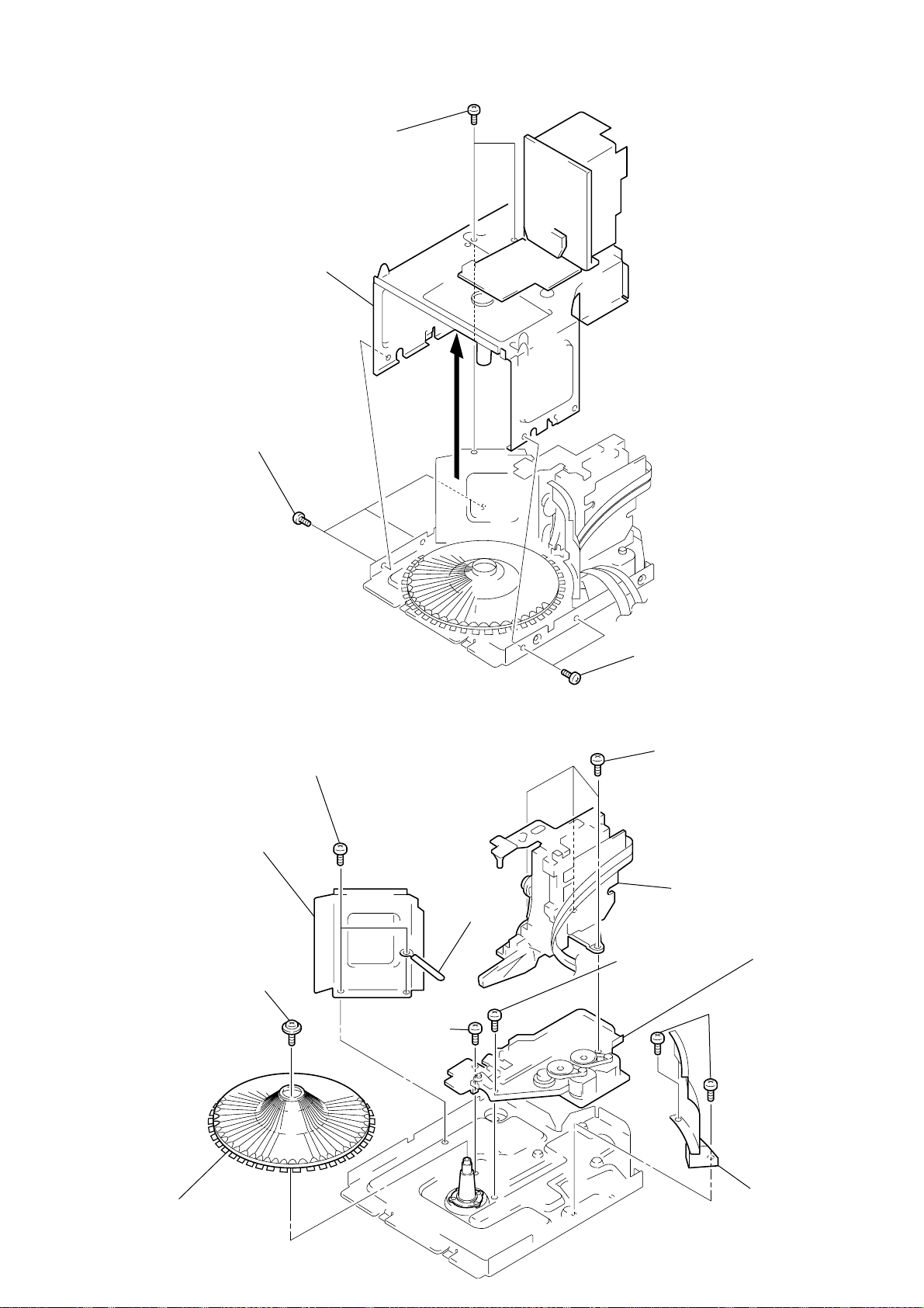
2-7. SUB CHASSIS
8
2 Three screws
(BVTP 3 × 8)
1 Two screws
(BVTT 3 × 8)
3 Sub chassis
2-8. CD MECHANISM DECK SECTION
5 Two screws
(BVTT 3 × 6)
7 Reinforcement
1 Screw
(PTPWH 2.6 × 8)
0 Screw
(BVTT 3 × 14)
6 Wire holder
2 Two screws
(BVTP 3 × 8)
Three screws
(BVTT 3 × 10)
9 Base (LOADING)
qa Screw
(BVTT 3 × 10)
qs Base (CDM)
3 Two screws
(BVTP 3 × 8)
2 Table (50)
4 Cover (CD)
11
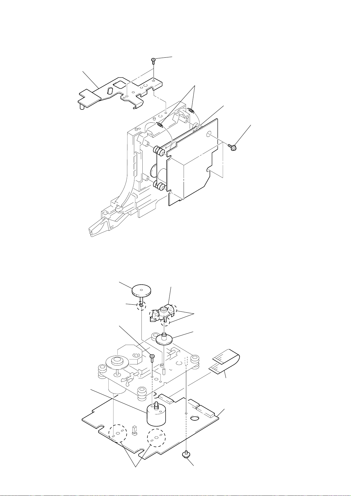
2-9. CD BASE UNIT
1 Two screws
(BTVP 3 × 8)
2 Bracket
3 Two tention springs
5 Base unit
4 Four screws
(PTPWH 2.6 × 8)
2-10. BD BOARD, SLED MOTOR (M102)
6 Gear (A) (S)
5 Claw
0 Two screws (P 2 × 3)
qa Sled motor
(M102)
8 Gear cover
7 Three claws
9 Gear (B) (RP)
1 Wire (flat type) (16 core)
4 BD board
12
3 Removal
four solders.
2 Screw (PTPWH 2 × 5)
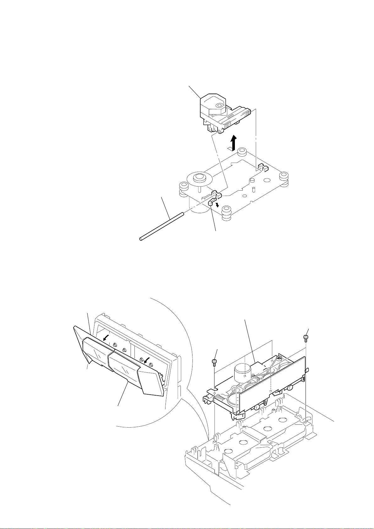
2-11. OPTICAL PICK-UP
3 Remove the optical
pick-up to direction
of the arrow A.
A
2 Sled shaft
2-12. TAPE MECHANISM DECK SECTION
2 Remove the cassette lid (L) assy
to direction of the arrow B.
B
A
1 Remove the cassette lid (R) assy
to direction of the arrow A.
1 Claw
4 Remove the tape mechanism
deck section.
3 Three screws
(BVTP 2.6 × 8)
3 Three screws
(BVTT 3 × 6)
13
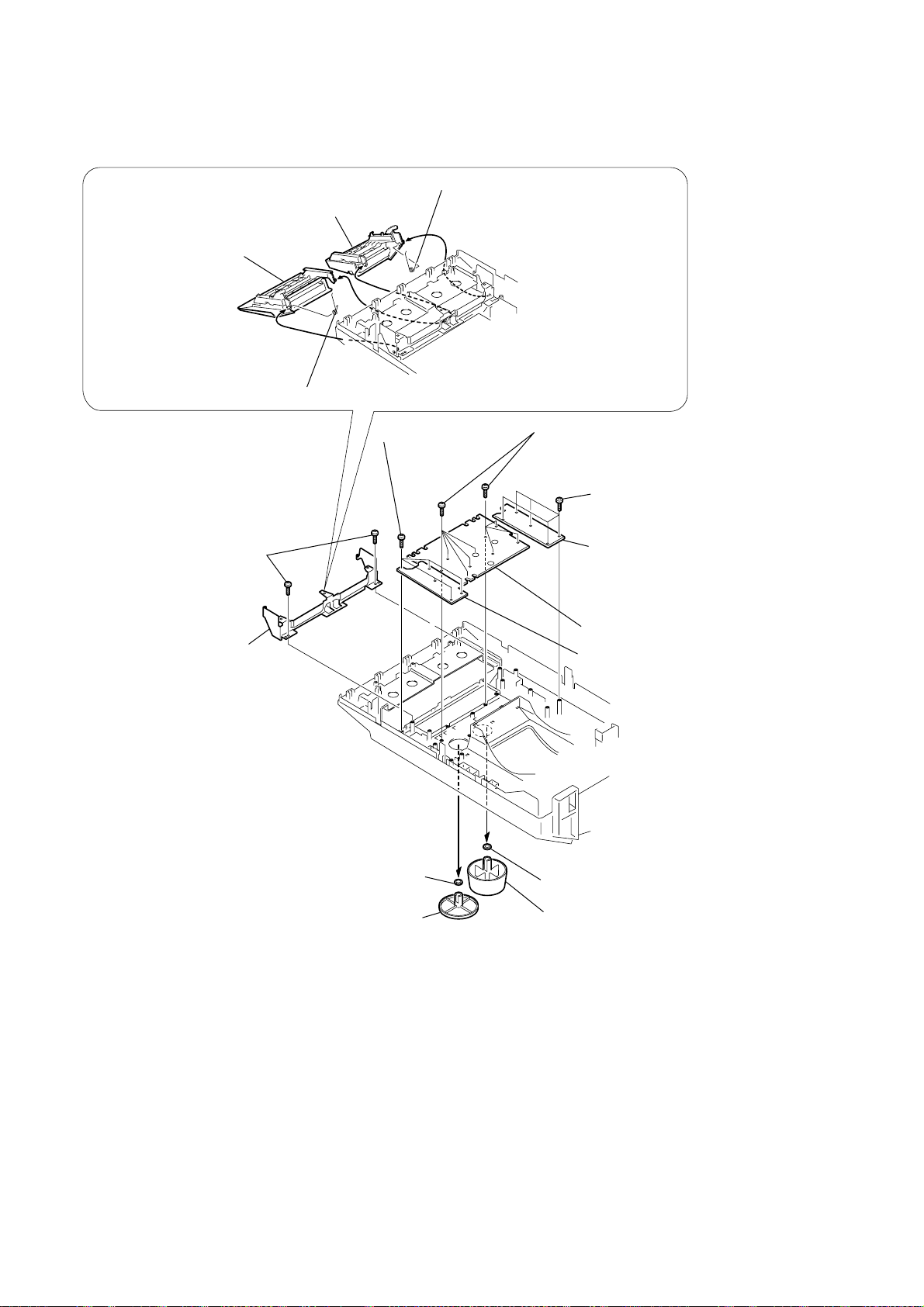
2-13. PANEL BOARD
3 Remove the
cassette lid (L) assy
3 Remove the
cassette lid (R) assy
5 Two screws
(BVTP 2.6 × 8)
6 Remove the
TC bracket
2
2
1
4 Remove the spring (B deck)
qa Five screws
(BVTP 2.6 × 8)
4 Remove the spring (A deck)
1
qa Nine screws
(BVTP 2.6 × 8)
qa Five screws
(BVTP 2.6 × 8)
qs Remove the panel (L) board
qf Remove the panel board
qd Remove the panel (R) board
14
8 Volume ring
7 Volume knob
9 Selector ring
0 Selector ring
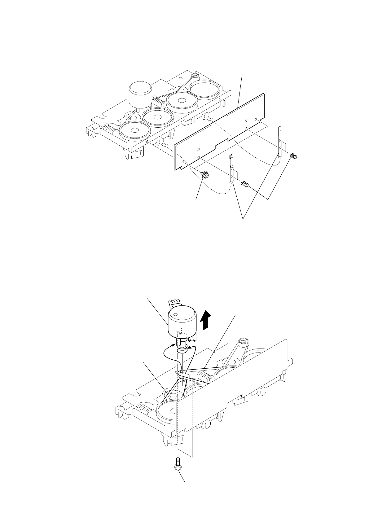
2-14. CASSETTE BOARD
o
4
4 CASSETTE board
2-15. CAPSTAN MOTOR (M1)
Remove the capstan motor
to direction of the arrow.
2 Remove the belt.
3 Two screws
(BVTT 2 × 4 (S))
1 Four rivets
2 Break the soldering of tw
flexible flat cables.
3 Remove the belt.
1 Two screws
(PS 2.6 × 5)
15

SECTION 3
TEST MODE
[MC Cold Reset]
* The cold reset clears all data including preset data stored in the
RAM to initial conditions. Execute this mode when returning
the set to the customer.
Procedure:
1. Press the three buttons x , ENTER and @/1 at the same
time.
2. The fluorescent indicator tube turns off for a moment and the
RAM is reset to the initial conditions.
[MC Hot Reset]
* This mode resets the set with the preset data kept stored in the
memory. This hot reset mode is performed also when the power
cord is plugged in and out.
Procedure:
1. Press the three buttons x , ENTER and FUNCTION at the
same time.
2. The fluorescent indicator tube turns off for a moment and the
RAM is reset to the initial conditions.
[CD Initial]
* The CD INITIAL clears all of the CD related data. Execute
this mode when returning the set to the customer.
Procedure:
1. Press the three buttons x , ENTER and CONTINUE/
STEREO/MONO at the same time.
2. The message “STANDBY” appears on the fluorescent indicator
tube and the CD related data is reset to the initial conditions.
[CD Line Test]
* The CD Line test displays the rotating time required for one
rotation by rotating the disc tray.
Procedure:
1. Press the three buttons x , ENTER and CLOCK/TIMER SET
at the same time. The CD PLAY LED and the CD PAUSE LED
flash alternately and the disc tray starts rotation.
2. The message “xx << y.y” appears on the fluorescent indicator
tube. The left numbers count up the discs starting from 1 to 51.
The left numbers “y.y” indicate the rotating time required for
one rotation by rotating the disc tray.
3. To exit the CD LINE test mode, execute the MC Hot Reset.
[CD Memo All Clear]
* The mode clears all contents of the CD disc memo. Execute
this mode when returning the set to the customer.
Procedure:
1. Press the two buttons MEMO INPUT and ENTER at the
same time.
2. The message “ALL ERASE” appears on the fluorescent indicator
tube and the CD disc memo is all cleared.
Procedure:
1. Press the three buttons x , ENTER and DISPLAY at the
same time. The set enters the GC test mode, and all of the
fluorescent tubes and LEDs turn on.
2. From this state, any one of the three modes MODEL NAME,
KEY CHECK and VACS can be selected. Go to step 3 to enter
the MODEL NAME test mode. Go to step 5 to enter the KEY
CHECK test mode. Go to step 11 to enter the VACS test mode.
3. [MODEL NAME test mode ] From the state of step 2, press the
CONTINUE/STEREO/MONO button. Every pressing of the
CONTINUE/STEREO/MONO button advances the following
check modes and displays in the given order. Model name
display, destination display, MC version display, GC version
display, DC version display, VC version display and CC version
display.
4. To exit the GC test mode and to return to the STANDBY mode,
press the x , ENTER and DISPLAY buttons again.
5. [KEY CHECK test mode ] You can enter this mode directly
from step 2. When you performed steps 3, perform steps 4,
then 1 and 2 before starting the step 5.
[KEY CHECK test mode ] From the GC test mode, press the
PROGRAM/TUNER MEMORY button to enter the key check
mode.
The display: K 1, J 0, V 0 appears.
6. The value after K indicates the number of times that the key is
pressed. 1 is displayed because the PROGRAM/TUNER
MEMORY button has already been pressed.
7. When other keys are pressed one after another, the key count
increases up to 43. The keys which have already been pressed,
are not counted.
8. The value after J indicates the number of clicks that the JOG
dial is rotated. The clockwise rotation increases the count value.
The counter-clockwise rotation decreases the count value.
9. The value after V also indicates amount of rotation of volume
control. The clockwise rotation increases the count value. The
counter-clockwise rotation decreases the count value.
10. To exit the GC test mode and to return to the STANDBY mode,
press the x , ENTER and DISPLAY buttons again.
11. [VACS test mode ] You can enter this mode directly from step
2. When you performed steps 3, perform steps 4, then 1 and 2
before starting the step 5.
[VACS test mode ] From the GC test mode, press the SHUFFLE
button to enter the VACS attenuation check mode. The display:
VOL NORMAL appears.
12. To exit the GC test mode and to return to the STANDBY mode,
press the x , ENTER and DISPLAY buttons again.
[Aging Mode]
The decks A and B are operated automatically for aging purpose.
When errors occur during aging, causes of errors are displayed and
the aging mode is stopped.
How to enter the aging mode
1. Turn on the main power. Install a playback tape to deck A and
install a blank tape to deck B.
2. Select TAPE A with the FUNCTION button.
3. Press the three buttons of x , ENTER and SHUFFLE at the
same time to enter the aging mode.
[GC Test Mode]
* This mode checks microprocessor version number, keys,
fluorescent tubes, LEDs and VACS (Variable Attenuation
Control System).
16
How to exit the aging mode.
Turn off the main power.
1. Rewind the tapes A and B. Tapes stop at the shut-off of tape A
and the aging mode advances to the next step.
The message: TAPE A AG-1 appears.

2. The tape A is played back in the FWD mode. After two minutes
of the FWD playback, the aging mode advances to the next
step.
The message: TAPE A AG-2 appears.
3. The tape A runs in fast forward. After two minutes of fast
forward, or at the shut-off point, the tape is stopped and the
aging mode advances to the next step.
The message: TAPE A AG-3 appears.
4. The tape A is played back in the RVS mode. After two minutes
of the RVS playback, the aging mode advances to the next step.
The message: TAPE A AG-4 appears.
5. The tape A is rewound and stops at the shut-off. The aging
mode advances to the next step.
The message: TAPE A AG-5 appears.
6. The tape B is played back in the FWD mode. After two minutes
of the FWD playback, the aging mode advances to the next
step.
The message: TAPE B AG-2 appears.
7. The tape B runs in fast forward. After two minutes of fast
forward, or at the shut-off point, the tape is stopped and the
aging mode advances to the next step.
The message: TAPE B AG-3 appears.
8. The tape B is played back in the RVS mode. After two minutes
of the RVS playback, the aging mode advances to the next step.
The message: TAPE B AG-4 appears.
9. The tape B is rewound and stops at the shut-off. The aging
mode advances to the next step.
The message: TAPE B AG-5 appears.
[AM TUNER STEP 9 kHz/10 kHz Selection Mode]
* Either the 9 kHz step or 10 kHz step can be selected for the AM
channel step.
Procedure:
1. Turn on the power and select TUNER using the FUNCTION
button.
2. Select AM with the TUNER/BAND button and turn off the
power.
3. Press the two buttons ENTER and @/1 at the same time. The
main power is turned on and the other frequency step of the
previous mode is selected and displayed. “AM 9 k STEP” or
“AM 10 k STEP”
[CD SRAM Test Mode]
Procedure:
1. Turn on the power and select CD using the FUNCTION button.
2. Press the three buttons x , ENTER and DBFB at the same
time.
3. The message “SRAM OK” appears on the fluorescent indicator
tube.
[GC VACS ON/OFF Mode]
Procedure:
1. Press the two buttons DELETE and @/1 at the same time.
2. The message “VACS ON” or “VACS OFF” appears on the
fluorescent indicator tube.
17
SECTION 4
MECHANICAL ADJUSTMENTS
• TAPE MECHANISM DECK SECTION
Precaution
1. Clean the following parts with a denatured alcohol-moistened
swab:
record/playback heads pinch rollers
erase head rubber belts
capstan idlers
2. Demagnetize the record/playback head with a head demagnetizer.
3. Do not use a magnetized screwdriver for the adjustments.
4. After the adjustments, apply suitable locking compound to the
parts adjusted.
5. The adjustments should be performed with the rated power supply voltage unless otherwise noted.
• Torque Measurement
Mode
FWD
FWD
back tension
REV
REV
back tension
FF/REW
FWD tension
REV tension
Torque meter Meter reading
CQ-102RC
CQ-102RC
CQ-102C
CQ-102C
CQ-201B
CQ-403A
CQ-403R
3.06 N • m to 6.96 N • m
31 to 71 g • cm
(0.43 – 0.98 oz • inch)
0.19 N • m to 0.58 N • m
2 to 6 g • cm
(0.02 – 0.08 oz • inch)
3.06 N • m to 6.96 N • m
31 to 71 g • cm
(0.43 – 0.98 oz • inch)
0.19 N • m to 0.58 N • m
2 to 6 g • cm
(0.02 – 0.08 oz • inch)
6.96 N • m to 14.02 N • m
71 to 143 g • cm
(0.98 – 1.99 oz • inch)
9.80 N • m
100 g or more
(3.53 oz or more)
9.80 N • m
100 g or more
(3.53 oz or more)
• CD MECHANISM DECK SECTION
To adjust the mechanism section, enter the mechanism section adjustment mode.
For how to enter the mechanism section adjustment mode, refer to each adjustment section.
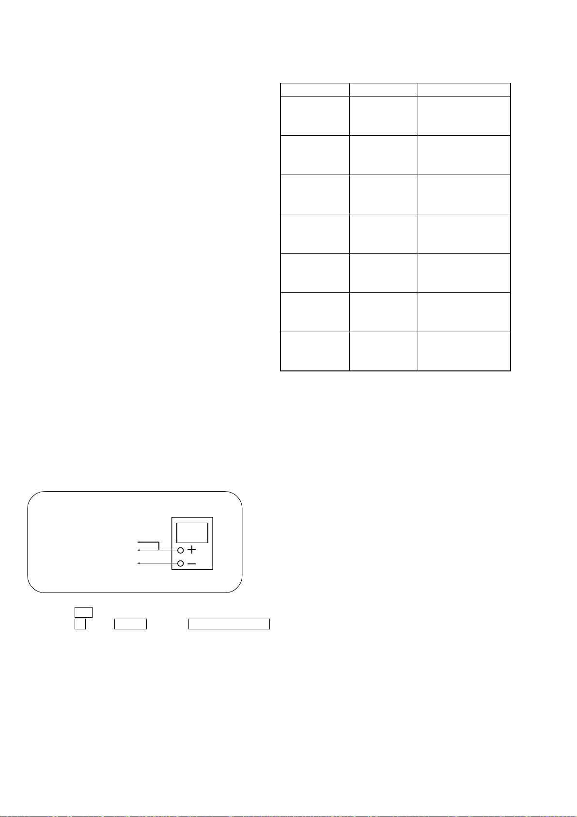
DISC SENSOR ALIGNMENT
1. Make sure that there is no disc in the unit.
2. Connect an oscilloscope to IC401rs, IC4014 of the MAIN board.
oscilloscope
IC401rs D.SENS (CH1)
IC4014 HHOUT (CH2)
GND
3. Press the @/1 button to turn ON the power.
4. Press the x button, ENTER button and CLOCK/TIMER SET button simultaneously.
18
PLUS ONE
5. The disc table rotates in the clockwise direction. The disc table rotation time is displayed with “PLUS ONE” slit as a measuring point.
6. Measure the waveform of the oscilloscope when the disc table is rotating.
7. Move the holder (sensor) center so that the flat portion center at the top of the D.SENS (CH1) input waveform and the “H” center of
HHOUT (CH2) coincide.
D.SENS (CH1) waveform
Holder (sensor)
HHOUT (CH2) waveform
Fixed screw
Flat portion center of
D.SENS (CH1) waveform
8. Tighten the fixed screw to fix the disc table, then press the CLEAR button.
9. The disc table rotates in the counterclockwise direction. Measure the waveform and make sure that the flat portion center at the top of the
D.SENS (CH1) input waveform and the “H” center of HHOUT (CH2) coincide.
10. If the adjustment is not successful, press the CLEAR button to rotate the disc table in the clockwise direction, and perform steps 6 to 9.
Note: During the adjustment mode, the rotational direction is switched each time the CLEAR button is pressed.
Pressing the CHECK button enters the loading mode which will be described later. Pressing the CLEAR button rotates the disc table
again.
19
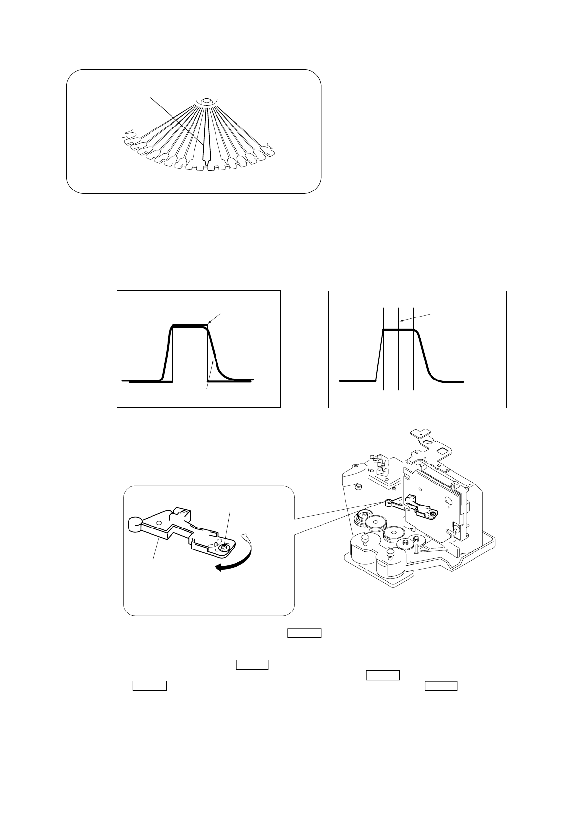
MAGNET ASSY ALIGNMENT
)
1. Check that there is no disc in the unit and then press the @/1 button to turn ON the power. Open the door, and set a disc in the PLUS
ONE slit.
2. Close the door, and while pressing the x button, ENTER button and CLOCK/TIMER SET button simultaneously.
3. Press the CHECK button, and set the loading mode.
4. Press the + J L button and chuck the disc.
5. Adjust the magnet assembly and magnet holder so that A = B as shown in the figure.
AB
Magnet ASSY
Magnet holder
Magnet ASSY
Screw (For adjustment)
DISC HOLDER A ALIGNMENT
1. Check that there is no disc in the unit and then press the @/1 button to turn ON the power. Open the door, and set a disc in the PLUS
ONE slit.
2. Close the door, and while pressing the x button, ENTER button and CLOCK/TIMER SET button simultaneously.
3. Press the CHECK button, and set the loading mode.
4. Press the + J L button and chuck the disc.
5. Press + J L or l j – button to stop the disc holder A slightly away from the disc.
6. Rotate and adjust the adjusting screw so that the center of the disc and that of the disc holder coincide.
Disc
Disc holder A
a
a = b
Disc holder A
Disc
b
Screw (For adjustment
20
SECTION 5
ELECTRICAL ADJUSTMENTS
DECK SECTION
0 dB = 0.775 V
1. Demagnetize the record/playback head with a head demagnetizer.
2. Do not use a magnetized screwdriver for the adjustments.
3. After the adjustments, apply suitable locking compound to the
parts adjust.
4. The adjustments should be performed with the rated power supply voltage unless otherwise noted.
5. The adjustments should be performed in the order given in this
service manual. (As a general rule, playback circuit adjustment
should be completed before performing recording circuit adjustment.)
6. The adjustments should be performed for both L-CH and RCH.
7. Switches and controls should be set as follows unless otherwise
specified.
• Test Tape
Tape Signal Used for
P-4-A100 10 kHz, –10 dB Azimuth Adjustment
WS-48B 3 kHz, 0 dB Tape Speed Adjustment
P-4-L300 315 Hz, 0 dB Level Adjustment
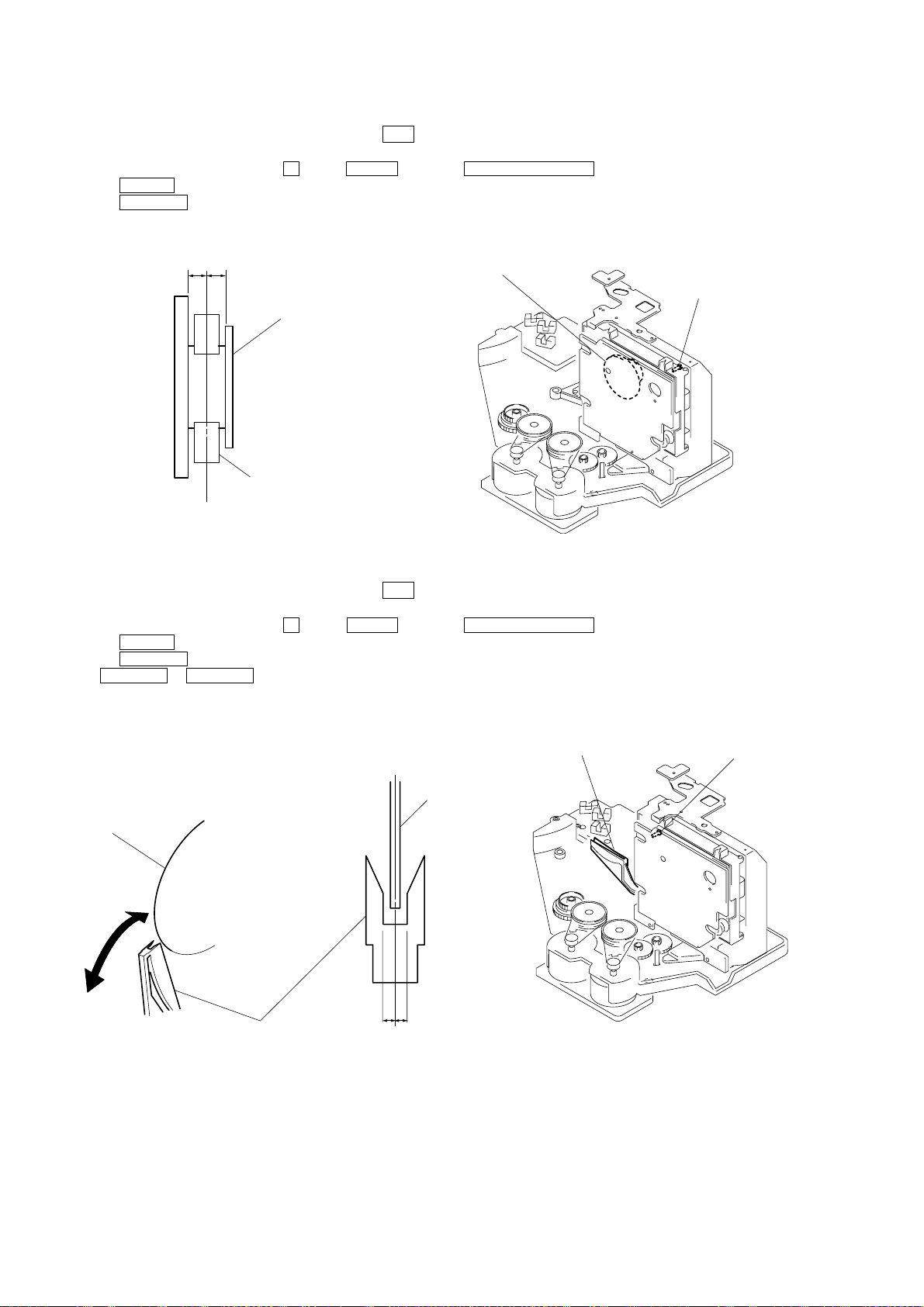
Record/Playback Head Azimuth Adjustment
DECK A/B
Note: Perform this adjustments for both decks
Procedure:
1. Mode: Playback
test tape
P-4-A100
(10 kHz, –10 dB)
main board
CN301B
Pin qs (L-CH)
Pin qa (R-CH)
set
main board
CN301B
Pin 0 (GND)
level meter
+
–
2. Turn the adjustment screw and check output peaks. If the peaks
do not match for L-CH and R-CH, turn the adjustment screw
so that outputs match within 1 dB of peak.
Output
level
within
1dB
L-CH
peak
R-CH
peak
within
1dB
Screw
position
L-CH
peak
Screw
position
R-CH
peak
3. Mode: Playback
test tape
P-4-A100
(10 kHz, –10 dB)
L-CH
MAIN
board
CN301B
set
R-CH
in phase 45 ° 90° 135° 180°
pin qs
pin 0
L
R
qa
pin
waveform of oscilloscope
good
oscilloscope
V
wrong
H
4. After the adjustments, apply suitable locking compound to the
pats adjusted.
Adjustment Location: Playback Head (Deck A).
Record/Playback/Erase Head (Deck B).
21
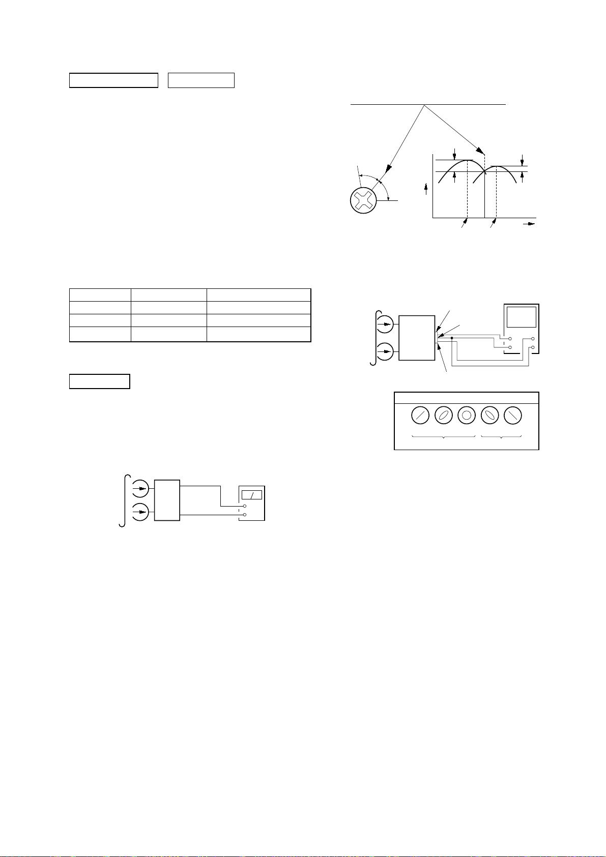
Tape Speed Adjustment DECK A/B
(
)
r
Note: Start the Tape Speed adjustment as below after setting to the test
mode.
Procedure:
1. Press the @/1 button to turn ON the power.
2. Press the x button, ENTER button and TIMER SELECT
button simultaneously.
(The “VOLUME” on the fluorescent indicator tube will blink
while in the test mode.)
To exit from the test mode, press the @/1 button.
Mode: Playback
test tape
WS-48B
(3 kHz, 0 dB)
set
main board
CN301B (Pin qs : L-CH)
frequency counte
+
–
Pin qa : R-CH
1. Insert the WS-48B into the deck.
2. Press the H button on the deck.
3. Adjust RV1001 on the LEAF SW board so that frequency
counter reads 3,000 ± 90 Hz.
Adjustment Location: LEAF SW board
[MAIN BOARD] (Component Side)
CN301B
CN402
[CASSETTE BOARD] (Component Side)
VR301
PB
LEVEL
28
19
IC301
CN401
216
115
12
1211
CN301
IC501
11 1
12 2
Sample Value of Wow and filter
W, RMS (JIS) within 0.3%
(test tape: WS-48B)
Playback level Adjustment DECK A/B
Procedure:
Mode: Playback
test tape
P-4-L300
(315 Hz, 0 dB)
set
Phones jack (HP801)
level meter
+
–
Adjust DECK A/B: VR301 (R-CH) so the level meter reading
becomes the adjustment limits below.
Adjustment Level:
CN301 PB level: 155 to 275 mV (– 14 to – 9 dB) level difference
between the channels: within ± 0.5 dB
Adjustment Location: CASSETTE board
[LEAF SW BOARD] (Component Side)
TAPE SPEED
(NORMAL)
RV1001
CN1001
22
CD SECTION
IC102
IC101
TP
(VC)
TP
(TE)
TP
(FE)
TP
(RF)
TP
(PLCK)
CN101
CN102
CN103
TP
(DVDD)
TP
(TOFF)
Note :
1. CD Block is basically designed to operate without adjustment.
Therefore, check each item in order given.
2. Use YEDS-18 disc (3-702-101-01) unless otherwise indicated.
3. Use an oscilloscope with more than 10 MW impedance.
4. Clean the object lens by an applicator with neutral detergent
when the signal level is low than specified value with the
following checks.
oscilloscope
BD board
TP (FE)
TP (VC)
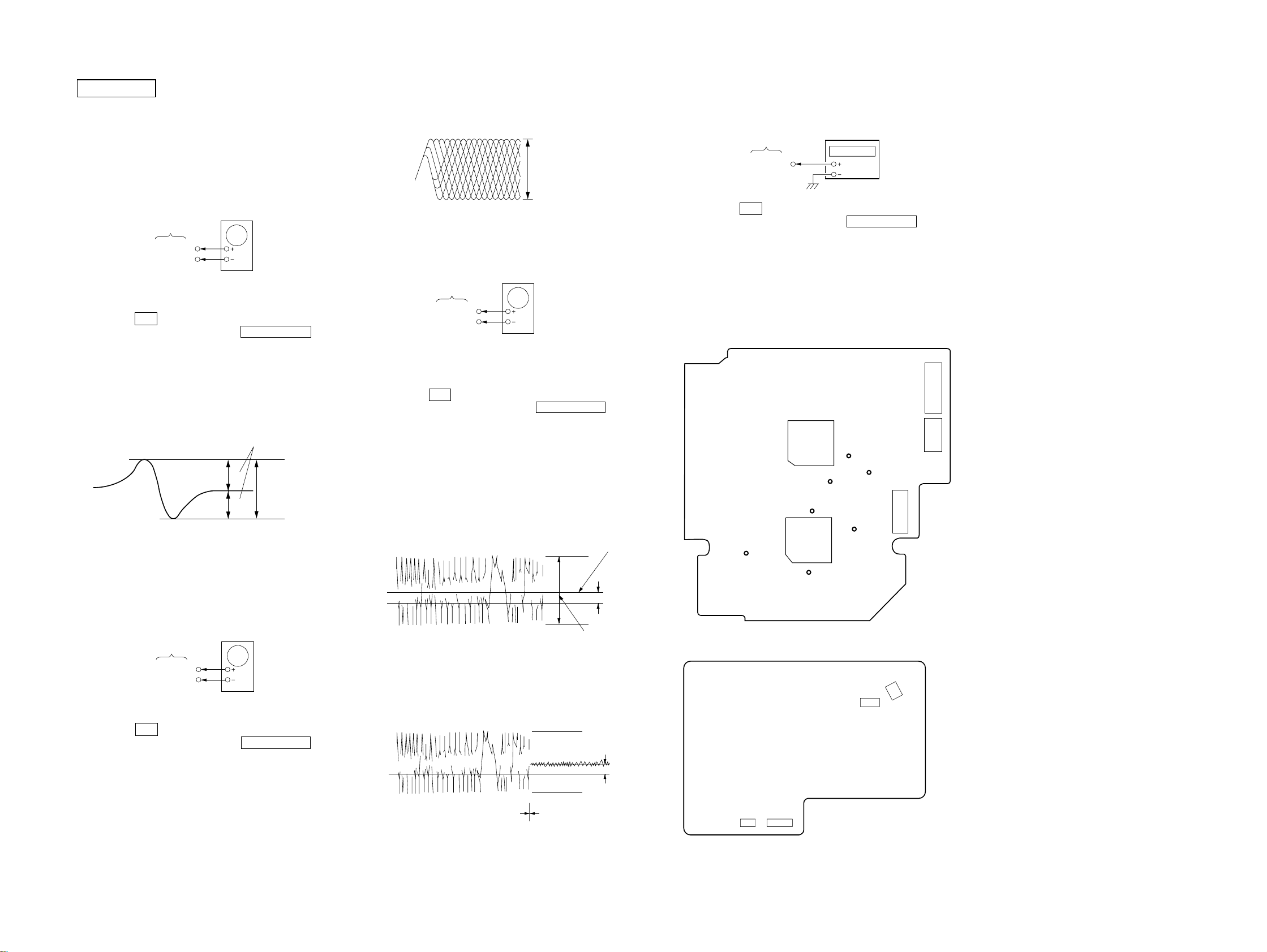
S Curve Check
Procedure :
1. Connect the oscilloscope to TP (FE) of the BD board.
2. Press the @/1 button to turn ON the power .
3. Open the front cover, and press the CD PLUS ONE button.
4. Set the disc (YEDS-18) into the “PLUS ONE” slit.
5. Close the front cover, and chuck the disc.
6. The first track will be played back automatically.
7. Check the oscilloscope waveform (S-curve) is symmetrical
between A and B. And confirm peak to peak level within 1.8 ±
0.6 Vp-p.
S-curve waveform
symmetry
A
within 1.8 ± 0.6Vp-p
B
8. Turn OFF the power.
Note : • Try to measure several times to make sure than the ratio
of A : B or B : A is more than 10 : 7.
• Take sweep time as long as possible and light up the
brightness to obtain best waveform.
RF Level Check
oscilloscope
BD board
TP (RF)
TP (VC)
Procedure :
1. Connect the oscilloscope to TP (RF) of the BD board.
2. Press the @/1 button to turn ON the power.
3. Open the front cover, and press the CD PLUS ONE button.
4. Set the disc (YEDS-18) into the “PLUS ONE” slit.
5. Close the front cover, and chuck the disc.
6. Playback the fifth track of the disc.
7. Confirm that oscilloscope waveform is clear and check RF sig-
8. Turn OFF the power.
nal level is correct or not.
Note : A clear RF signal waveform means that the shape “◊” can be
clearly distinguished at the center of the waveform.
RF signal waveform
VOLT/DIV : 200mV
TIME/DIV : 500ns
level : 1.8 ± Vp-p
+0.3
–0.2
E-F Balance (Traverse) Check
The procedure for this checking method differs for when a general
remote control unit is used and not used.
oscilloscope
BD board
TP (TE)
TP (VC)
1. Solder lead wires to TP (DVDD) and TP (TOFF) on the BD
board severally.
2. Connect the oscilloscope to TP (TE) of the BD board.
3. Press the @/1 button to turn ON the power.
4. Open the front cover, and press the CD PLUS ONE button.
5. Set the disc (YEDS-18) into the “PLUS ONE” slit.
6. Close the front cover, and chuck the disc.
7. Playback the fifth track of the disc.
8. Short-circuit the lead wire connected at step 1. (The tracking
servo is turned OFF)
9. Check the level B of the oscilliscope's waveform and the A
(DC voltage) of the center of the Traverse waveform.
Confirm the following :
A/B × 100 = less than ± 10%
Traverse waveform
0V
Center of the waveform
B
A (DC voltage)
level : 0.7 ± 0.3 Vp-p
10. Disconnect the lead wire short-circuited at step 8. (The tracking
servo is turned ON.) Confirm the C (DC voltage) is almost
equal to the A (DC voltage) is step 8.
Traverse waveform
C (DC
0V
Tracking servo
OFF
Tracking servo
ON
voltage)
11. Turn OFF the power, and remove the lead wire connected at
step 1.
RF PLL Free-run Frequency Check
Procedure :
1. Connect the frequency counter to TP (PLCK) of the BD board.
frequency counter
2. Press the
BD board
TP (PLCK)
@/1 button to turn ON the power.
3. Open the front cover, and press the CD PLUS ONE button.
4. Set the disc (YEDS-18) into the “PLUS ONE” slit.
5. Close the front cover, and chuck the disc.
6. Playback the fifth track of the disc.
7. Confirm that reading on frequency counter is 4.3218 MHz ±
30 kHz.
Adjustment Location :
[ BD BOARD ] — CONDUCTOR SIDE —
[ MAIN BOARD ] — COMPONENT SIDE —
IC501
11 1
12 2
CN402
28
19
CN301B
CN401
216
115
23
23
HCD-M500AV
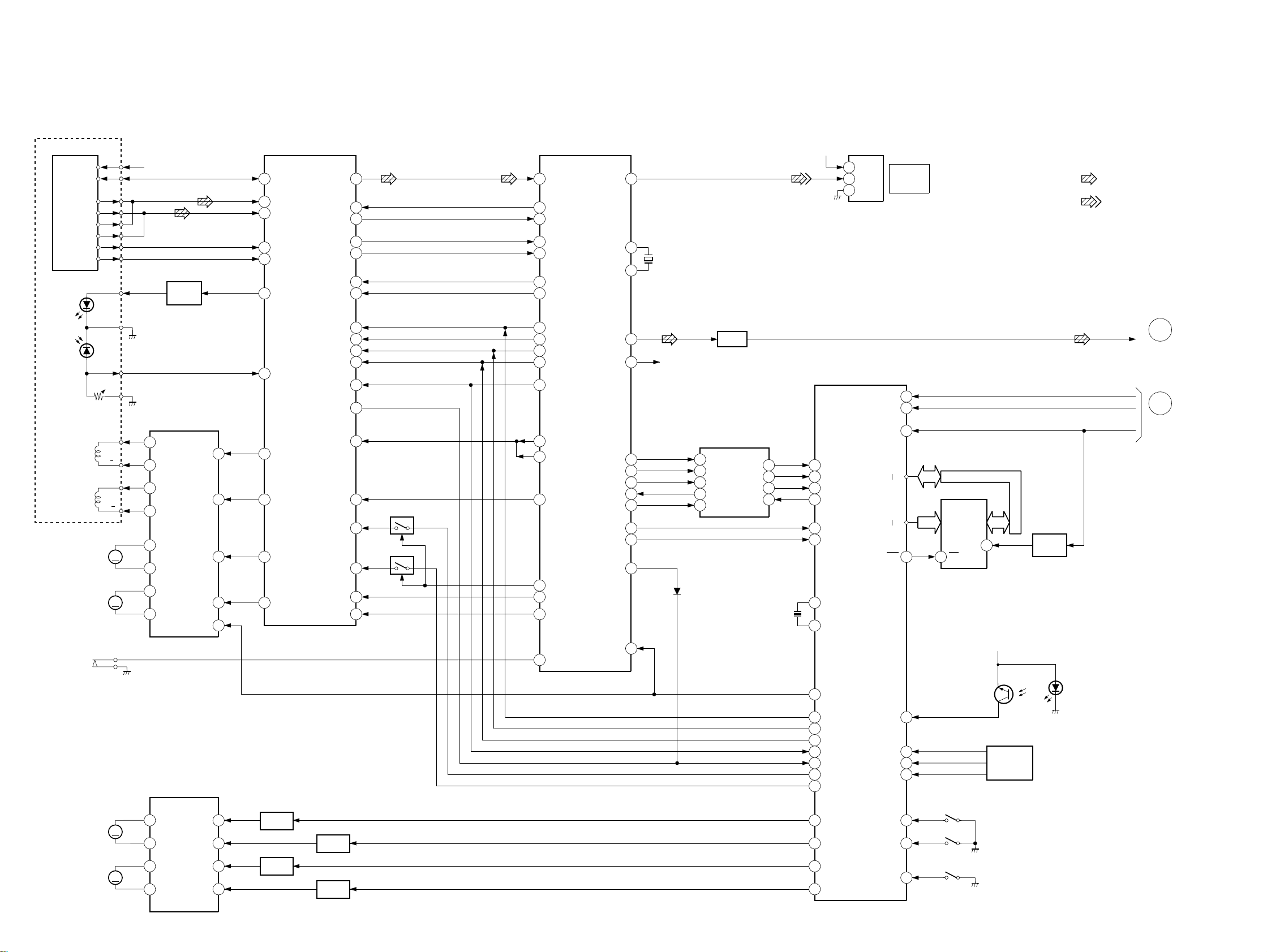
6-1. BLOCK DIAGRAM – CD SECTION –
OPTICAL PICK-UP
BLOCK
(KSM-213BFN/C2NP)
DETECTOR
VCC
VC
A
B
C
D
E
F
LD
A+5V
Q103
LD
DRIVER
SECTION 6
DIAGRAMS
FOCUS/TRACKING/
SLED/SPINDLE SERVO
RF AMP
IC101
58
VR
2
FIN 1
1
FIN 2
3
E
4
F
62
LDD
RF SM
TES
HFL
DIGITAL SIGNAL
PROCESSOR
IC102
41
44SLI
49DEF
36
37
33JP+
32JP-
10
EFMI
9
EFMO
1
DEFI
16
TES
15
HFL
19
JP+
20
JP-
D OUT
31
XI
45
XO
44
X101
16.9344MHz
A+5V
IC402
2
VDD
1
D IN
3
GND
CD
DIGITAL
OUT
• SIGNAL PATH
:CD
:DIGITAL OUT
FOCUS
COIL
TRACKING
COIL
M102
SLED
MOTOR
M101
SPINDOL
MOTOR
S101
LIMIT
GND
PD
VR
FCS/TRK COIL
SL/SP MOTOR
DRIVER
IC103
F+
F
T+
T
M
M
18
V06
V IN 3
15
17
V05
19
V07
20
V08
8
V04
7
V03
6
V02
V01
5
V IN 4
V02
V IN 1
MUTE
22
10
3
2
63
LDS
16
FD
15
TO
29
SLD
27
SPD
CLK
TGL
DRF
SLOF
SL+
SL-
CV-
52DATA
50
CL
51
CE
53
34
54
38
35TOFF
Q102
31
Q101
30
40CV+
39
56
COIN
61
4.2M
57
CQCK
54
RWC
18
TGL
14
V/P
25
CONT2
17
TOFF
26
CONT3
12
CLV+
13
CLV-
27
CONT4
L CH
R CH
PW
SFSY
16M
SBCK
SBSY
WRQ
SQOUT
PDO
RESET
37
40
49
50
60
51
47
53
55
3
58
R CH
D151
Q471
BUFFER
CD CHANGER
CONTROL
IC401
IIC DATA
80
IIC CLK
78
CD TEXT
DECODER
IC104
2
SBSO
4
WFCK
5
MCK
1
EXCK
3
SCOR
SRDT
SCLK
12
11
13DQSY
6XMODE
X401
10MHz
66
65
64
67
55
49
32
31
SRDT
SCLK
DQSY
XMODE
WRQ
SQOUT
XTAL
EXTAL
RESET
D0
D7
A0
A14
WE
30
8
SRAM
IC411
29
27
WE
815
CE
20
+5V
Q411
RESET
SW
CD L
IIC DATA
IIC CLK
RESET
A
AMP
SECTION
(Page 25)
B
MAIN
SECTION
(Page 26)
2
BD RESET
50
COIN
48
COCK
58
RWC
57
TGL
54
DRF
47
MOTOR DRIVER
IC461
Q464,468
8
M601
LOADING
MOTOR
TABLE
MOTOR
09
M602
M
M
OUT1+
9
OUT1-
11
OUT2+
OUT2-
10
R IN 1
F IN 1
R IN 2
F IN 2
3
2
16
17
MOTOR
CONTROL
Q461,465
MOTOR
CONTROL
Q463,467
MOTOR
CONTROL
Q462,466
MOTOR
CONTROL
24
24
59
76
77
75
74
SL+
SL-
LD OUT
LD IN
TBL L
TBL R
DOWN SW
TSENS 1
TSENS 2
TSENS 3
UP SW
DOOR SW
42D SENS
62
61
63
70
71
69
Q51 D51
DISC
SENSOR
TABL
SENSOR
IC51-53
S51
(UP)
S52
(DOWN)
S413
(DOOR)
DISC
SENSOR
– MAIN SECTION –
CD
SECTION
(Page 24)
MAIN
SECTION
(Page 26)
MAIN
SECTION
(Page 26)
DVD
INPUT
09
J01
MD/VIDEO
IN
(AUDIO)
FRONT
REAR
CENTER
WOOFER
A
D
C
REC IN L
TUNER L
L
J201
L
L
CD L
PB L
R CH
Q161,162
MIX
AMP
R CH
IC251
57
4
5
6
PRO LOGIC PROCESSOR
72
74
77
78
76
79
80
8 9 27
IC181
SELECTOR
IC201
DATA
SCK
REQ
IC501(2/2)
MASTER
CONTROL
98
6
1011
12
1
9
14
3
17
22
23
24
IC101
SOUND PROCESSOR
Q195,196
SWITCH
IC251
3
1
Q131
67 69
6566
PL CE
PL CLK
DVD SEL
PL DOUT
Q293
Q292
Q291
SPEANA
MUTE
MUTE
MUTE
MUTE
Q294,295
MUTE
SWITCH
70 71 1
SCL
SDA
MAIN
SECTION
(Page 26)
Q263,
264
MUTE
SWITCH
MUTE REAR
MUTE CENTER
E
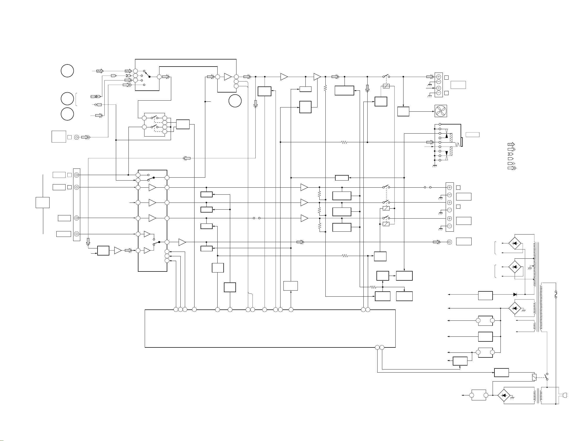
HCD-M500AV
IC141 IC801
31 1126
21
22
TDA DATA
Q141,143 Q145
MUTE
SWITCH
JW815
CONTROL
79
63 62 75 74 61 68
TDA CLK
DBFB H/N
STK MUTE
DBFB ON/OFF
Q171,172
MUTE
LINE MUTE
MUTE
Q741-743
POWER
AMP
MUTE
IC831(1/3)
16
IC831(2/3)
15 10
IC831(3/3)
16 18
OVER LOAD
DET.
Q197
SWITCH
Q841
OVER LOAD
DET.
Q842
OVER LOAD
DET.
Q881
OVER LOAD
DET.
Q801
F RELAY
RY731
Q732,733
LATCH
DRIVER
RY771
RY772
Q771,772
LATCH
DRIVER
Q703 Q721
LATCH
DRIVER
PROTECT
DC AMP
PL RELAY
PWR SAVE
CD POWER
27 28
Q751,752
MUTE
SWITCH
PROTECT
SWITCH
Q711,712Q701,702
OVER HEAT
DET.
R CH
R CH
JW842
-VP
M+13V
M+7V
A+9V
P+5V
P+5V CD
L
R
J801
J103
JK801
FRONT
SPEAKER
M751
(FAN)
L
REAR
SPEAKER
R
CENTER
SPEAKER
SUPER
WOOFER
Q921,922
B+
SWITCH
HP801
PHONES
FRONT
REAR
Q931 D836
-30V
REG.
IC922
+7V
3 1
REG
Q901-904
+9V
REG
IC921
+5V
3 1
REG
FOR
AMP
FOR
AMP
• R-CH is omitted
• SIGNAL PATH
: CD
: AUDIO
: PB (DECK A)
: PB (DECK B)
: REC
: MD/VIDEO
+VE
-VE
+VE
-VE
Q991
RELAY
DRIVER
VF2
VF1
D951
D961
D901-904
T991
POWER
TRANSFORMER
RY991
F992
25
25
+5.6V
IC931
+5.6V
3 1
REG
D831,832
D931,932
T992
AC IN
 Loading...