

Sony HCD-LF1H Service Manual
SERVICE MANUAL
Sony Corporation
Home Audio Division
Published by Sony Techno Create Corporation
US Model
Canadian Model
AEP Model
UK Model
E Model
Australian Model
Chinese Model
DVD PLAYER
9-887-283-04
2006L16-1
© 2006.12
Ver. 1.3 2006.12
SPECIFICATIONS
HCD-LF1H
HCD-LF1H is control unit (DVD player) in DAV-LF1H.
This system incorporates with Dolby* Digital and Dolby Pro Logic (II)
adaptive matrix surround decoder and the DTS** Digital Surround System.
* Manufactured under license from Dolby Laboratories.
“Dolby”, “Pro Logic”, and the double-D symbol are trademarks of Dolby
Laboratories.
** Manufactured under license from Digital Theater Systems, Inc.
“DTS” and “DTS Digital Surround” are trademarks of Digital Theater
Systems, Inc.
Model Name Using Similar Mechanism NEW
Mechanism T ype AUR-M1
• Abbreviation
CND : Canadian model
RU : Russian model
AUDIO POWER SPECIFICATIONS
for the US model
POWER OUTPUT AND
TOTAL HARMONIC
DISTORTION
(FTC Output Power) : Front L/Front R/Center:
60 W/ch 4 ohms at 170 20,000 Hz, 0.7 % THD
Surround L/Surround R:
60 W/ch 3.5 ohms at 170 20,000 Hz, 0.7 % THD
Subwoofer: 110 W/ch 1.5
ohms at 40 - 170 Hz, 0.7 %
THD
Super Audio CD/DVD system
Laser Semiconductor laser
(Super Audio CD/DVD:
λ = 645 – 660 nm)
(CD: λ = 770 – 800 nm)
Emission duration:
continuous
Signal format system NTSC/PAL
Video section
Outputs
VIDEO: 1 Vp-p 75 ohms
S VIDEO:
Y: 1 Vp-p 75 ohms
C: 0.286 Vp-p 75 ohms
C
AEP, UK, RU:
EURO AV:
VIDEO: 1 Vp-p 75 ohms
R/G/B: 0.7 Vp-p 75 ohms
EXCEPT AEP, UK, RU:
OMPONENT:
Y: 1 Vp-p 75 ohms
PB/CB, PR/CR: 0.7 Vp-p
75 ohms
Inputs VIDEO 1: 1 Vp-p 75 ohms
VIDEO 2: 1 Vp-p 75 ohms
Dimensions (approx.) 570 × 168× 56 mm
(22
1
/2 × 6 5/8 × 2 1/4 inches)
(w/h/d)
570 × 188 × 99 mm
(22
1
/2 × 7 1/2 × 4 inches)
(w/h/d) with stand
Mass (approx.) 4.2 kg (9 lb 5 oz)
4.7 kg (10 lb 6 oz) with
stand
Design and specifications are subject to change
without notice.
2
HCD-LF1H
Caution – The use of optical instruments with this
product will increase eye hazard.
Do not install the appliance in a confined space, such as a bookcase
or built-in cabinet.
To prevent fire, do not cover the ventilation of the apparatus with
news papers, table-cloths, curtains, etc. And don’t place lighted
candles on the apparatus.
To prevent fire or shock hazard, do not place objects filled with
liquids, such as vases, on the apparatus.
Notes on chip component replacement
• Never reuse a disconnected chip component.
• Notice that the minus side of a tantalum capacitor may be
damaged by heat.
Flexible Circuit Board Repairing
• Keep the temperature of the soldering iron around 270 °C
during repairing.
• Do not touch the soldering iron on the same conductor of the
circuit board (within 3 times).
• Be careful not to apply force on the conductor when soldering
or unsoldering.
UNLEADED SOLDER
Boards requiring use of unleaded solder are printed with the leadfree mark (LF) indicating the solder contains no lead.
(Caution: Some printed circuit boards may not come printed with
the lead free mark due to their particular size)
: LEAD FREE MARK
Unleaded solder has the following characteristics.
• Unleaded solder melts at a temperature about 40 °C higher
than ordinary solder.
Ordinary soldering irons can be used but the iron tip has to be
applied to the solder joint for a slightly longer time.
Soldering irons using a temperature regulator should be set to
about 350 °C.
Caution: The printed pattern (copper foil) may peel away if
the heated tip is applied for too long, so be careful!
• Strong viscosity
Unleaded solder is more viscou-s (sticky, less prone to flow)
than ordinary solder so use caution not to let solder bridges
occur such as on IC pins, etc.
• Usable with ordinary solder
It is best to use only unleaded solder but unleaded solder may
also be added to ordinary solder.
SAFETY-RELATED COMPONENT WARNING!!
COMPONENTS IDENTIFIED BY MARK 0 OR DOTTED LINE
WITH MARK 0 ON THE SCHEMATIC DIAGRAMS AND IN
THE PARTS LIST ARE CRITICAL TO SAFE OPERATION.
REPLACE THESE COMPONENTS WITH SONY PARTS WHOSE
PART NUMBERS APPEAR AS SHO WN IN THIS MANUAL OR
IN SUPPLEMENTS PUBLISHED BY SONY.
ATTENTION AU COMPOSANT AYANT RAPPORT
À LA SÉCURITÉ!
LES COMPOSANTS IDENTIFIÉS PAR UNE MARQUE 0 SUR
LES DIAGRAMMES SCHÉMATIQUES ET LA LISTE DES
PIÈCES SONT CRITIQUES POUR LA SÉCURITÉ DE
FONCTIONNEMENT. NE REMPLACER CES COM- POSANTS
QUE PAR DES PIÈCES SONY DONT LES NUMÉROS SONT
DONNÉS DANS CE MANUEL OU DANS LES SUPPLÉMENTS
PUBLIÉS PAR SONY.
Special Component Notice
The components identified by mark contain confidential
information.
Strictly follow the instructions whenever the components are repaired
and/or replaced.
Notice pour composants spéciaux
Les composants identifiés par la marque
contiennent des
informations confidentielles.
Suivre scrupuleusement les instructions chaque fois qu’un
composant est remplacé et / ou réparé.
Ver. 1.2

3
HCD-LF1H
TABLE OF CONTENTS
1. SERVICING NOTES ................................................ 4
2. GENERAL ................................................................... 8
3. DISASSEMBLY
3-1. Disassembly Flow ........................................................... 11
3-2. Cover (Rear) Assy, Holder (HDMI) ................................ 12
3-3. LED Board ...................................................................... 13
3-4. TOUCH Board ................................................................ 14
3-5. Front Section ................................................................... 15
3-6. Bracket (SYS-A) Assy..................................................... 15
3-7. Back Panel (HCD) ........................................................... 16
3-8. FL Board.......................................................................... 16
3-9. DVD Mechanism [Mech Module (AUR-M1)]
Section-1.......................................................................... 17
3-10. DVD Mechanism [Mech Module (AUR-M1)]
Section-2.......................................................................... 18
3-11. DVD Mechanism [Mech Module (AUR-M1)]
Section-3.......................................................................... 19
3-12. Shield Plate (DMB) ......................................................... 20
3-13. MAIN Board.................................................................... 21
3-14. DMB14 Board ................................................................. 22
4. TEST MODE ............................................................... 23
5. ELECTRICAL ADJUSTMENTS .......................... 26
6. DIAGRAMS
6-1. Block Diagram — RF Section —................................... 28
6-2. Block Diagram — MAIN Section — ............................. 29
6-3. Block Diagram — HDMI Section — ............................. 30
6-4. Block Diagram — TOUCH Section — .......................... 31
6-5. Printed Wiring Board — DMB14 Board (Side A) — .... 32
6-6. Printed Wiring Board — DMB14 Board (Side B) — .... 33
6-7. Schematic Diagram — DMB14 Board (1/7) — ............. 34
6-8. Schematic Diagram — DMB14 Board (2/7) — ............. 35
6-9. Schematic Diagram — DMB14 Board (3/7) — ............. 36
6-10. Schematic Diagram — DMB14 Board (4/7) —............. 37
6-11. Schematic Diagram — DMB14 Board (5/7) —............. 38
6-12. Schematic Diagram — DMB14 Board (6/7) —............. 39
6-13. Schematic Diagram — DMB14 Board (7/7) —............. 40
6-14. Printed Wiring Board — MAIN Board (Side A) —....... 41
6-15. Printed Wiring Board — MAIN Board (Side B) — ....... 42
6-16. Schematic Diagram — MAIN Board (1/4) — ............... 43
6-17. Schematic Diagram — MAIN Board (2/4) — ............... 44
6-18. Schematic Diagram — MAIN Board (3/4) — ............... 45
6-19. Schematic Diagram — MAIN Board (4/4) — ............... 46
6-20. Printed Wiring Board — FL Board— ............................ 47
6-21. Schematic Diagram — FL Board—............................... 48
6-22. Printed W iring Boards
— TOUCH Board, LED Board— ................................... 49
6-23. Schematic Diagram
— TOUCH Board, LED Board— ................................... 50
7. EXPLODED VIEWS
7-1. Overall Section ................................................................ 63
7-2. Front Section ................................................................... 64
7-3. Chassis Section ................................................................ 65
7-4. DVD Mechanism Section ................................................ 66
8. ELECTRICAL PARTS LIST .................................. 67
4
HCD-LF1H
SECTION 1
SERVICING NOTES
Note about CDs/DVDs
The system can play CD-ROMs/CD-Rs/CD-RWs recorded in the
following formats:
– audio CD format
– video CD format
– MP3 audio tracks and JPEG image files of format conforming to
ISO 9660 Level 1/Lev el 2, or its extended f ormat, Joliet Adapter
The system can play DVD-ROMs/DVD+RWs/DVD-RWs/
DVD+Rs/D VD-Rs recorded in the following formats:
– MP3 audio tracks, JPEG image files of format conforming to
UDF (Universal Disc Format)
Note of replacing the EEPROM (IC103 and IC706) on the
DMB14 board
EEPROM (IC103 and IC706) on the DMB14 board cannot exchange with
single. When EEPROM (IC103 and IC706) on the DMB14 board (A-1199885-A etc.) is damaged, exchange the entire mounted board.
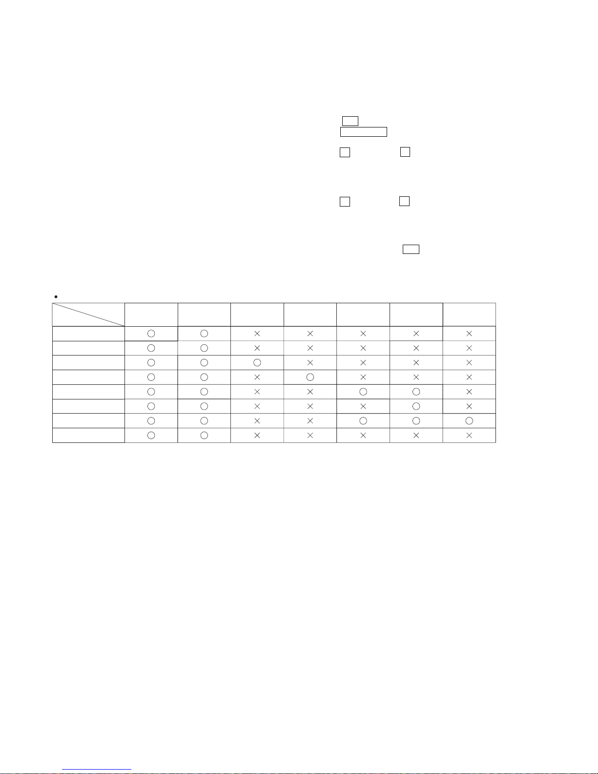
The units that are required for the system operation check during repair service
Unit
required for checking
Unit to be
checked
DVD player:
HCD-LF1H
Subwoofer:
SA-WSLF1H
Front speaker:
SS-TSLF1H
Center speaker:
SS-CTLF1H
Surround speaker (L):
SA-TSLF1H
AC adaptor:
AC-LF1HR
Surround speaker (R):
SS-TSLF1HW
Remote commander:
RM-ADP011
DVD player:
HCD-LF1H
Subwoofer:
SA-WSLF1H
Front speaker:
SS-TSLF1H
Center speaker:
SS-CTLF1H
Surround speaker
(L): SA-TSLF1H
AC adaptor:
AC-LF1HR
Surround speaker
(R): SS-TSLF1HW
*1 Only the defective unit.
Units with
a
mark: The units that are required for the system operation check during repair service.
(However, there can be a case that some units of the system need to not be brought into repair shop depending on the unit.that become defective.)
*1
DISC SLOT LOCK
The disc slot lock function for the antitheft of an demonstration
disc in the store is equipped.
Procedure :
1. Press the ?/1 button to turn the set on.
2. Press the FUNCTION button to set DVD function.
3. Insert a disc.
4. Press the x button and the A button simultaneously for f ive
seconds.
5. The message “LOCKED” is displayed and the slot is locked.
Releasing Procedure :
1. Press the x button and the A button simultaneously for f ive
seconds, again.
2. The message “UNLOCKED” is displayed and the slot is
unlocked.
Note: When “LOCKED” is displayed, the slot lock is not released by
turning power on/off with the ?/1 button.
Ver. 1.1
5
HCD-LF1H
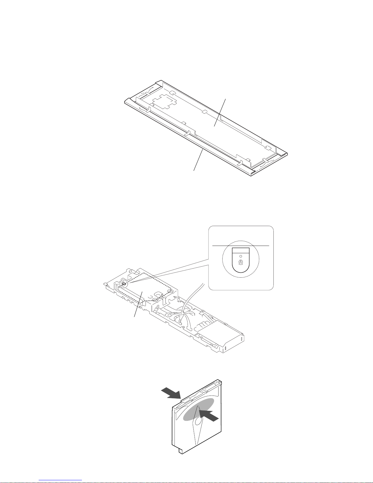
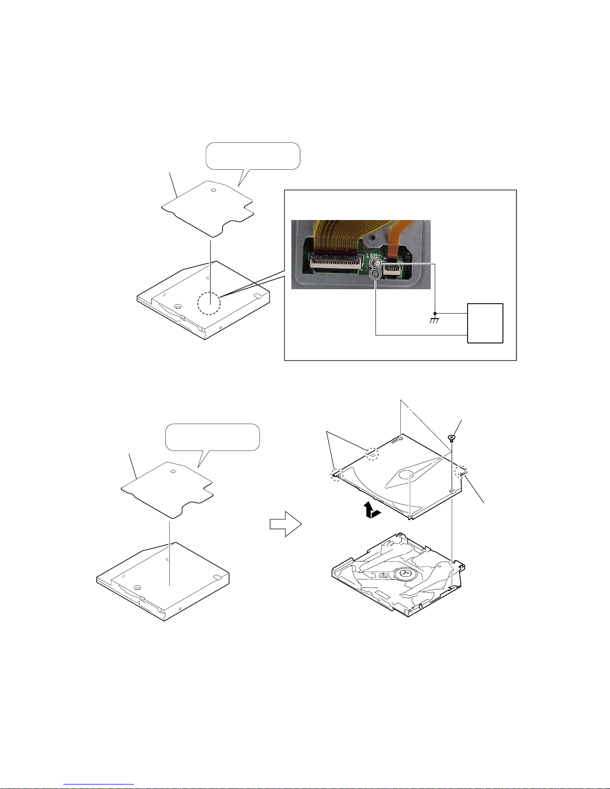
• PRECAUTION DVD MECHANISM [MECH MODULE (AUR-M1)] DISASSEMBLY
• PRECAUTION FRONT PART
The front part is easy to be scratched. Attach a protective sheet on the front part or remove
the front part before the repair work.
front part
protective sheet
When removing the mech module section (AUR-M1), create
a solder bridge to prevent the optical pick-up from breaking.
(Use a soldering iron with an antistatic earth.)
mech module (AUR-M1)
Do not hold the A part of mech module (AUR-M1).
Doing so may deform the module.
A
6
HCD-LF1H
•TO TAKE OUT DISC WHEN POWER SWITCH TURNS OFF (FORCE EJECT)
1. Load the disc using an external power supply.
4
claw
5
3
two claws
1
Remove the bottom seal.
2
three screws
2. If the loading motor is defective, disassemble the mech module (AUR-M1).
When re-assembling use
the new Bottom seal.
2
Remove the bottom seal.
3
Apply a DC voltage across LDM+ and LDM– on the board.
DC 2V to 3V
(+)
(–)
1
Disconnect FFC 50P (160), and them remove the mech module (AUR-M1).
*
Please refer to SECTION 3 DISASSEMBLY (See page 11) for the method removed by the mech module (AUR-M1).
When re-assembling use
the new Bottom seal.
DC power
supply
7
HCD-LF1H
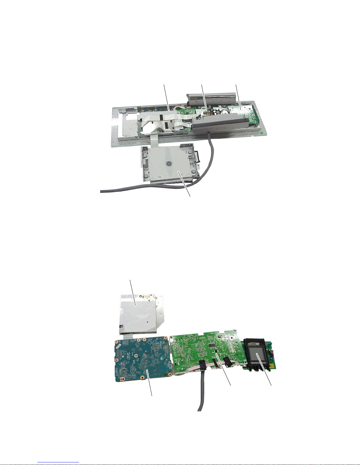
• SERVICE POSITION (MECH MODULE (AUR-M1))
• SERVICE POSITION (DMB14 BOARD AND MAIN BOARD)
mech module (AUR-M1)
DMB14 board MAIN board FL board
mech module (AUR-M1)
DMB14 board
MAIN board FL board
8
HCD-LF1H
SECTION 2
GENERAL
This section is extracted
from instruction manual.
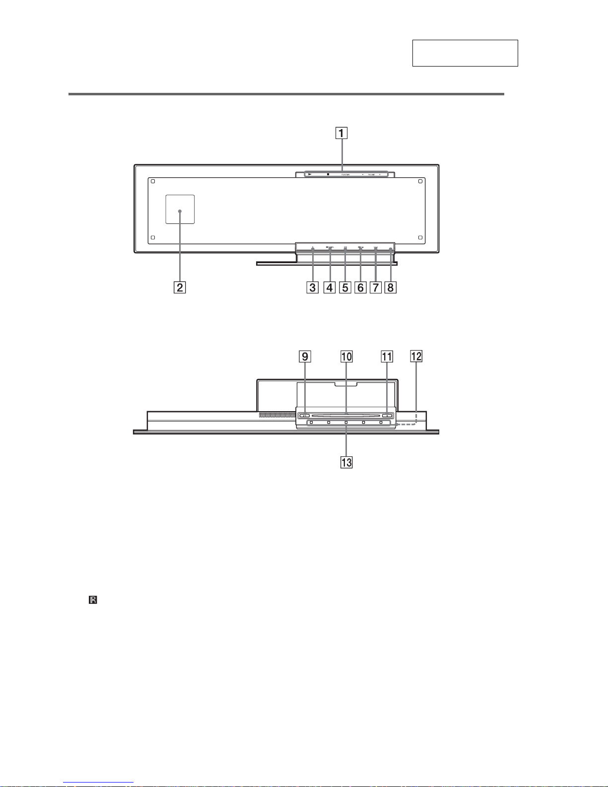
Front Panel (control unit)
Top Panel
A Soft-touch button indicators (42)
B Front panel display (115)
C 1 (standby) indicator (42)
D DOLBY DIGITAL indicator
E DTS indicator
F DOLBY PRO LOGIC II indicator
G D.C.S. indicator
H (remote sensor) (10)
I [/1 (on/standby) (42)
J Disc slot (42)
K
Z
(eject)/DISC indicator (42)
L HDMI OUT jack (36)
M Soft-touch buttons (
N/x
/FUNCTION/
VOLUME –/+) (42)
When you press the soft-touch buttons qd,
the sof t touch indicators 1 light up.
9
HCD-LF1H
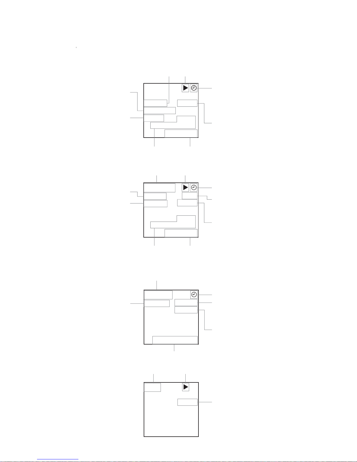
Front Panel Display
When playing back a DVD
When playing back a Super Audio CD, CD, VIDEO CD (without PBC functions), or MP3
DVD
11
MOVIE REP1
PROGRE
HDMI
TITLE
0.01.11
DVD
11
REP1
PROGRE
TITLE
0.01.11
Playing status
Current title/chapter number Playing time/remaining time
Current mode
Lights up when the MOVIE
or MUSIC mode is selected
(page 47).
Lights up when the system
outputs the progressive
signals (page 94).
Lights up when the sleep
timer is set (page 82).
Lights up when the HDMI
OUT jack is correctly
connected to HDCP (highbandwidth digital content
protection) compliant device
with HDMI or DVI (digital
visual interface) input
(page 36).
SA-CD
20
MULTI PBC
MUSIC REP1
TRK
28.11
Playing status
Current track number Playing time/remaining time
Current mode
Lights up when the MOVIE
or MUSIC mode is selected
(page 47).
Lights up when the sleep
timer is set (page 82).
Playing disc
Lights up during MULTI
channel playback. (Super
Audio CD only) (page 67)
PBC playback
(VIDEO CD only)
When listening to the radio
When playing back a JPEG file
FM 10
TUNED MONO
AUTO
108.0MHz
Monaural/Stereo effect
(page 76).
Lights up when the sleep
timer is set (page 82).
Lights up when a
station is received.
Current band and preset number
Current station
Lights up during the Auto
tuning (page 76).
CD
REP1
No Audio
Playing status
Current mode
Playing disc
10
HCD-LF1H
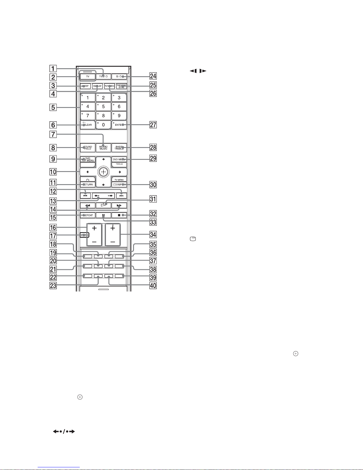
Remote control
A TV [/1 (on/standby) (79)
B TV button/TV mode indicator (79)
C SLEEP (82)
D DISPLAY (63)
E Number buttons
2) 3)
(52, 76, 78, 84)
F CLEAR (53, 77, 80)
-/--
3)
(78)
G MOVIE/MUSIC (47)
H SOUND FIELD (48)
I DVD TOP MENU (59)
J C/X/x/c, (ENTER) (30, 44, 52, 75, 84)
K O RETURN
3)
(54)
L ./> (42)
PRESET –/+ (76)
M (42)
c/C STEP (51)
N m/M (51)
/ (51)
TUNING –/+ (75)
O REPEAT (58)
P VOLUME +/– (42, 76, 98)
TV VOL +/–
3)
(79)
Q MUTING (42)
R AUDIO (59)
S PICTURE NAVI (53)
T PROGRESSIVE (94)
U DIMMER (83)
V FM MODE (76)
W DIRECT TUNING (76)
X [/1 (on/standby) (30, 42, 54, 76)
Y THEATRE SYN C (81)
Z TV/VIDEO (79)
wj ENTER
1) 3)
(30, 44, 52, 75, 84)
wk BASS/TREBLE (50)
wl DVD MENU (59)
TOOLS
3)
(79)
e; DISPLAY (31, 52, 84, 120)
TV MENU
3)
(79)
ea H (play)
2)
(42, 54)
es x (stop) (43, 54, 84)
ed X (pause) (43)
ef FUNCTION +/–
2)
(42, 44, 75)
TV CH +/–
3)
(79)
eg SUBTITLE (66)
eh ANGLE (65)
ej SA-CD/CD (67)
ek NIGHT (82)
el AMP MENU (44, 99, 124)
r; TUNER MENU (75)
1)
The ENTER wj button is the same function as the
(ENTER) 0 button.
2)
The 5, H, and FUNCTION + buttons have tactile
dots. Use the tactile dots as references when
operating the system.
3)
These buttons change to the TV operat ion but tons
when the remote is in TV mode. The remote is in TV
mode when the TV mode indicator 2 lights up by
pressing the TV button 2.
With the cover opened.
11
HCD-LF1H
SECTION 3
DISASSEMBLY
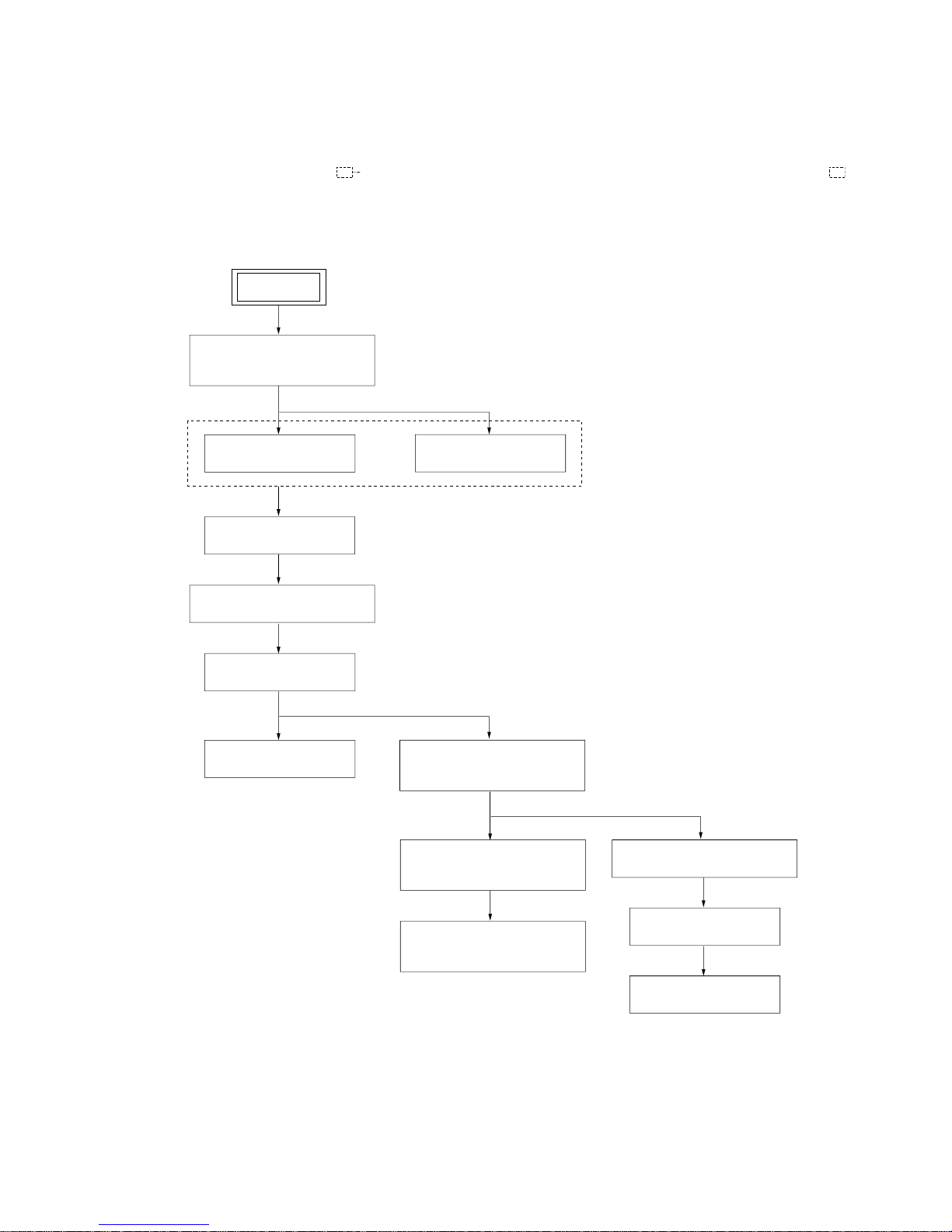
3-1. DISASSEMBLY FLOW
•This set can be disassembled in the order shown below.
•The dotted square with arrow (
) prompts you to move to the next job when all of the works within the dotted square ( ) are
completed.
SET
3-2. COVER (REAR) ASSY,
HOLDER (HDMI)
(Page 12)
3-3. LED BOARD
(Page 13)
3-4. T OUCH BOARD
(Page 14)
3-7. BACK PANEL (HCD)
(Page 16)
3-6. BRACKET (SYS-A) ASSY
(Page 15)
3-8. FL BOARD
(Page 16)
3-12. SHIELD PLATE (DMB)
(Page 20)
3-5. FRONT SECTION
(Page 15)
3-9. DVD MECHANISM
[MECH MODULE (AUR-M1)]
SECTION-1 (Page 17)
3-10. DVD MECHANISM
[MECH MODULE (AUR-M1)]
SECTION-2 (Page 18)
3-11. DVD MECHANISM
[MECH MODULE (AUR-M1)]
SECTION-3 (Page 19)
3-13. MAIN BOARD
(Page 21)
3-14. DMB14 BOARD
(Page 22)
12
HCD-LF1H
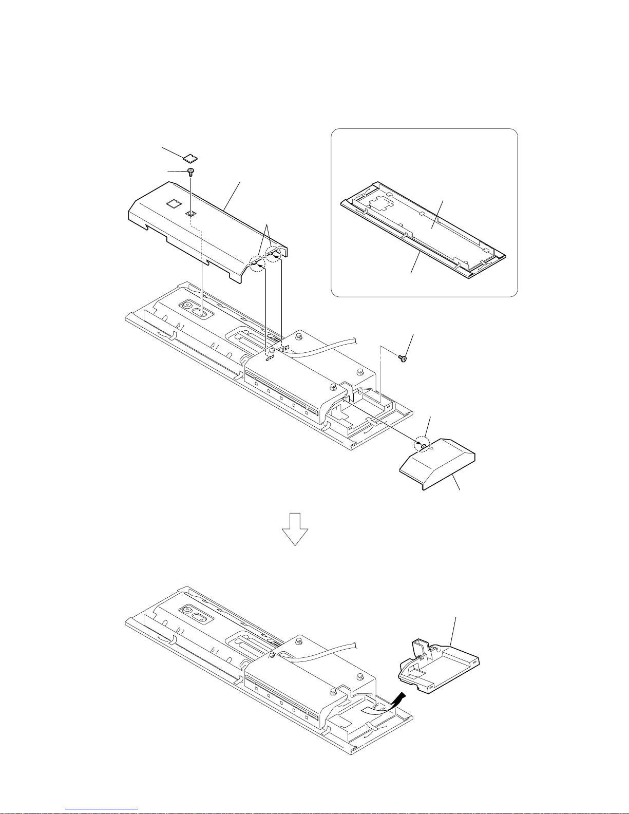
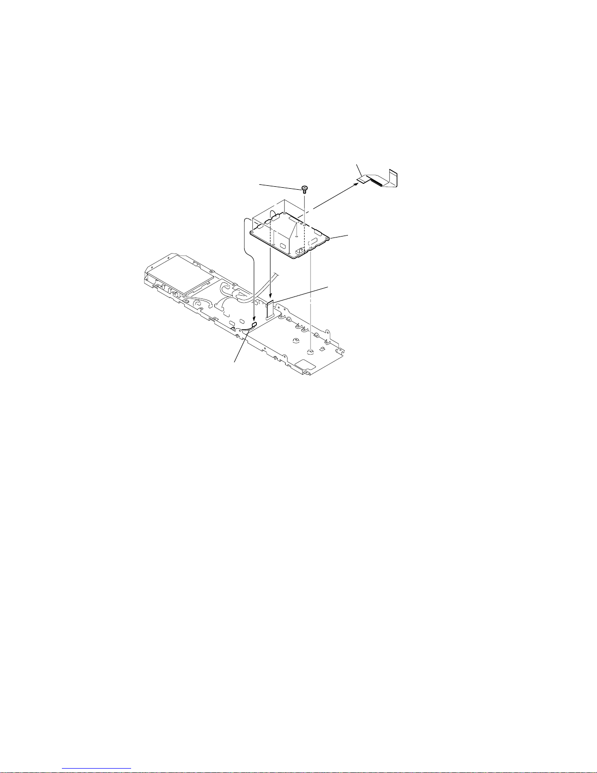
3-2. COVER (REAR) ASSY, HOLDER (HDMI)
Note: Follow the disassembly procedure in the numerical order given.
2
screw
(+BVTP 3
×
6)
7
screw
(+BVTP 3
×
6)
1
cover (screw)
3
two claws
4
cover (rear) assy
5
claw
6
cover (HDMI)
8
Remove the holder (HDMI)
in the direction of the arrow.
The front part is easy to be scratched.
Attach a protective sheet on the front
part or remove the front part before
the repair work.
front part
protective sheet
PRECAUTION THE MAIN UNIT DISASSEMBLY
13
HCD-LF1H
3-3. LED BOARD
6
two screws
(+BVTP 2.6
×
8)
7
panel (bottom) assy
1
connector
10P (CN309)
3
two claws
2
two screws (SS)
4
8
connector
10P (CN721)
5
Remove the saranet cushion.
9
three screws
(+BVTP 2.6
×
8)
qa
LED board
q;
holder (SF)
14
HCD-LF1H
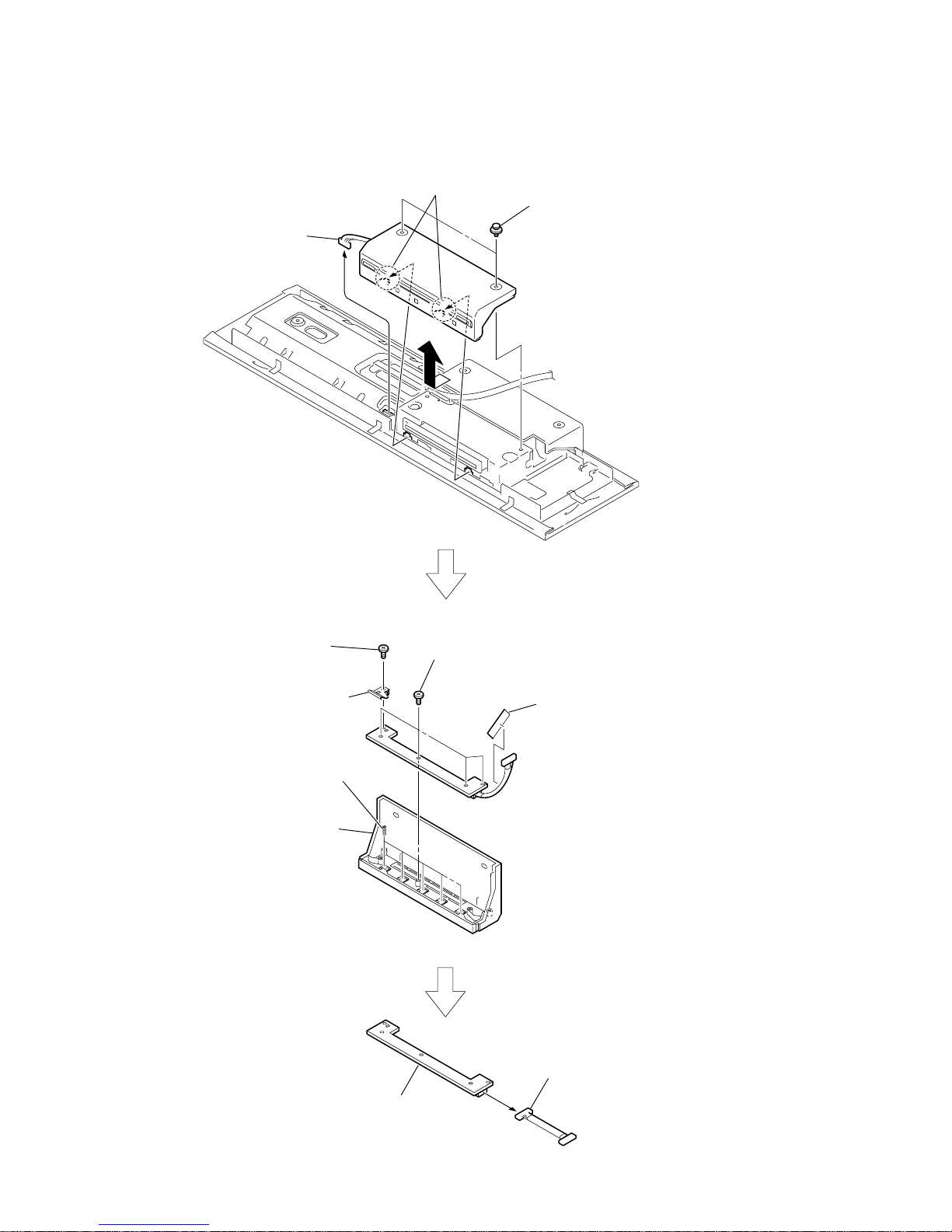
3-4. TOUCH BOARD
q;
panel (top) assy
9
five coil springs (function)
5
Remove the saranet cushion.
qa
connector
13P (CN700)
6
screw
(+BVTP 2.6
×
8)
7
ground plate (function)
8
four screws
(+BVTP 2.6
×
8)
qs
TOUCH board
2
two screws (SS)
1
connector
13P (CN304)
3
two claws
4
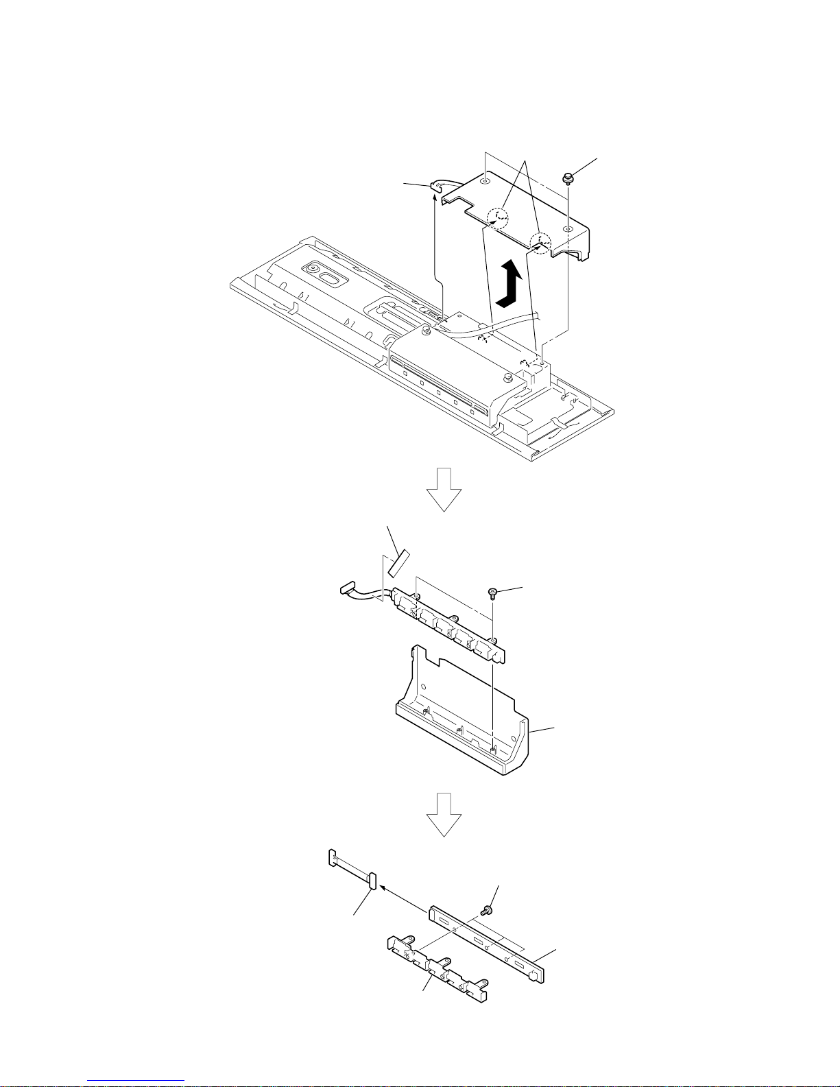
15
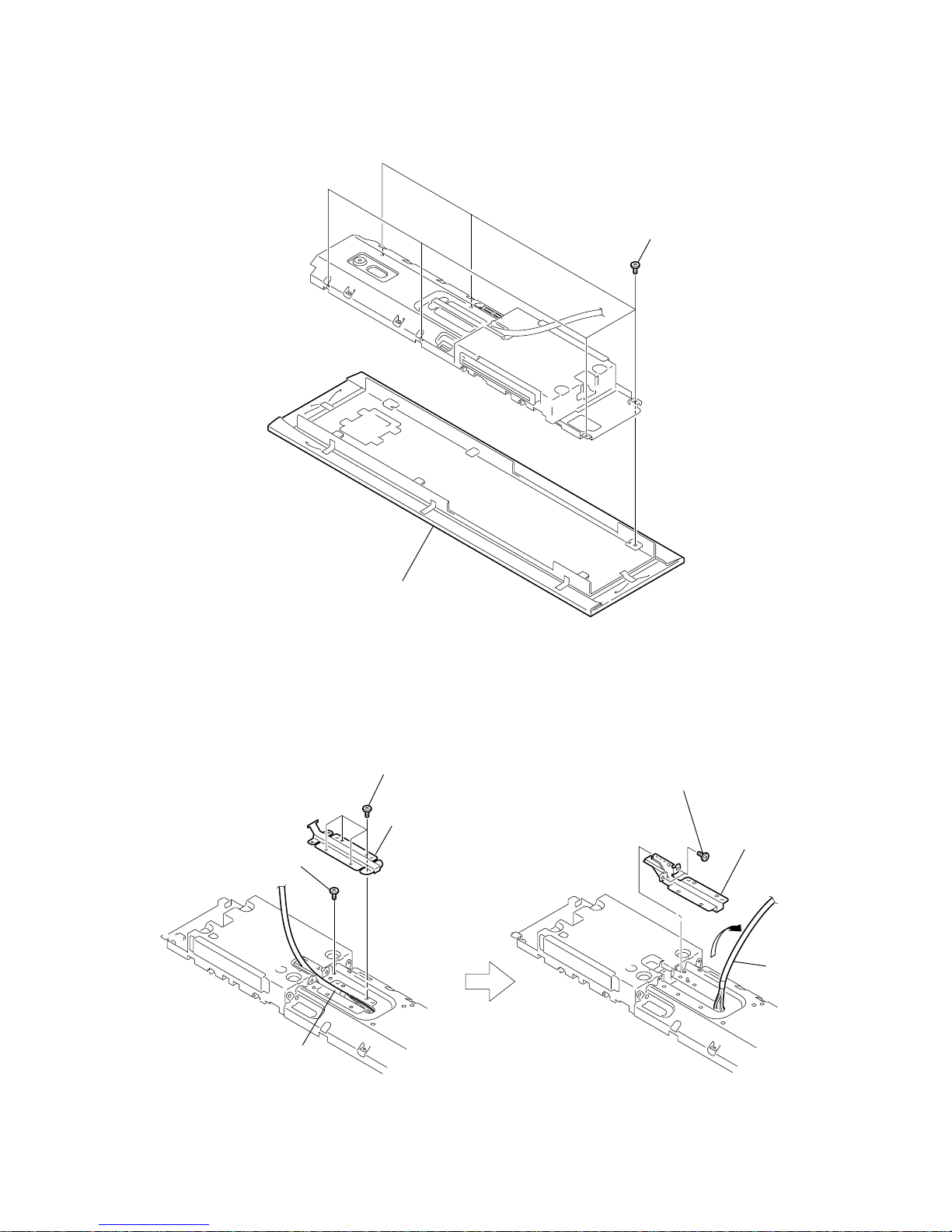
HCD-LF1H
1
six screws
(+BVTP 3 × 6)
2
front section
1
four screws
(+BVTP 3 × 6)
2
bracket (SYS-B)
6
bracket (SYS-A)
assy
cable (system
)
cable (system)
5
4
two screws
(+BVTP 3 × 6)
3
screw
(+BVTP 3
×
6)
3-5. FRONT SECTION
3-6. BRACKET (SYS-A) ASSY
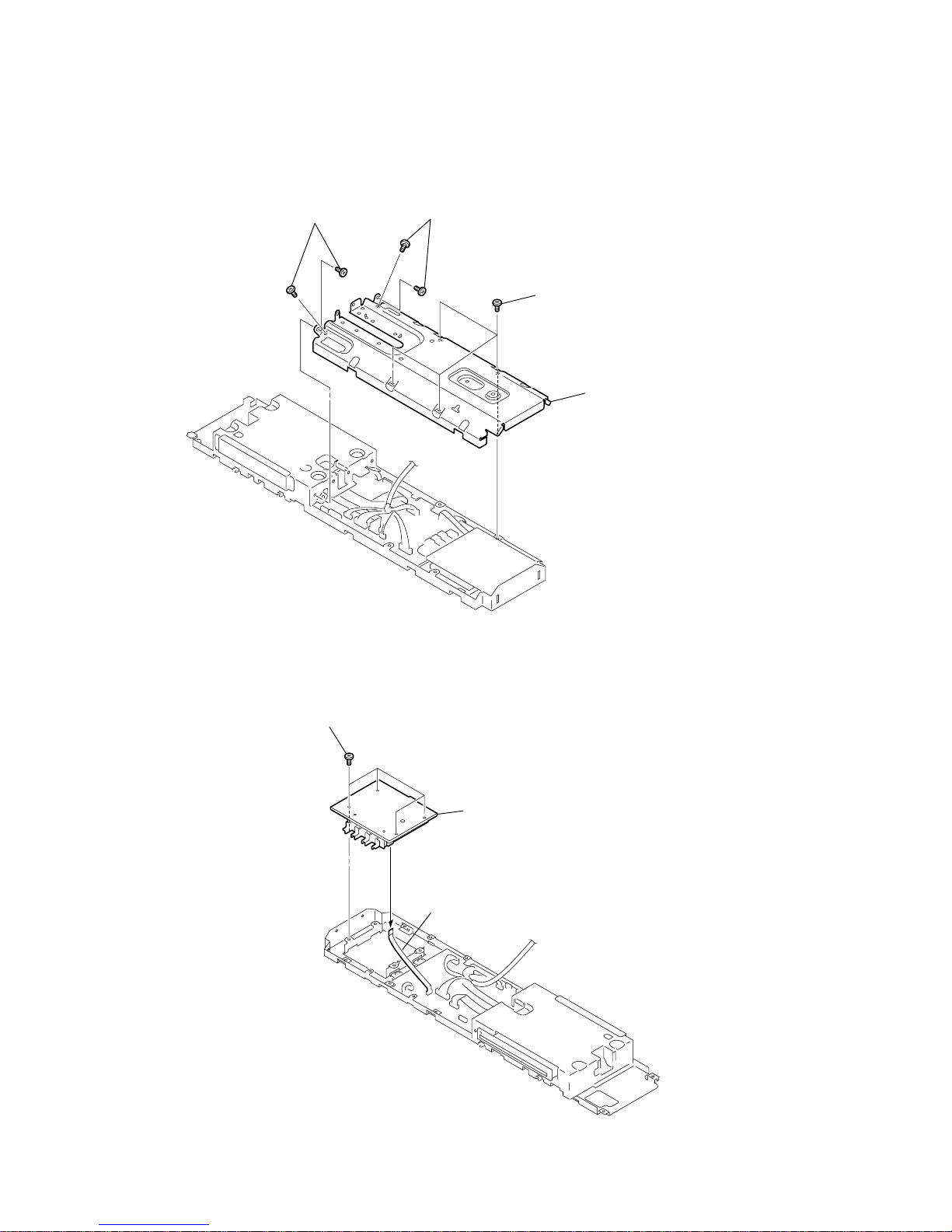
16
HCD-LF1H
3
four screws
(+BVTP 3
×
6)
1
two screws
(+BVTP 3
×
6)
2
two screws
(+BVTP 3
×
6)
4
back panel (HCD
)
3
FL board
1
four screws
(+BVTP 3
×
6)
2
FFC 7p (100)
7core (CN951)
3-7. BACK PANEL (HCD)
3-8. FL BOARD
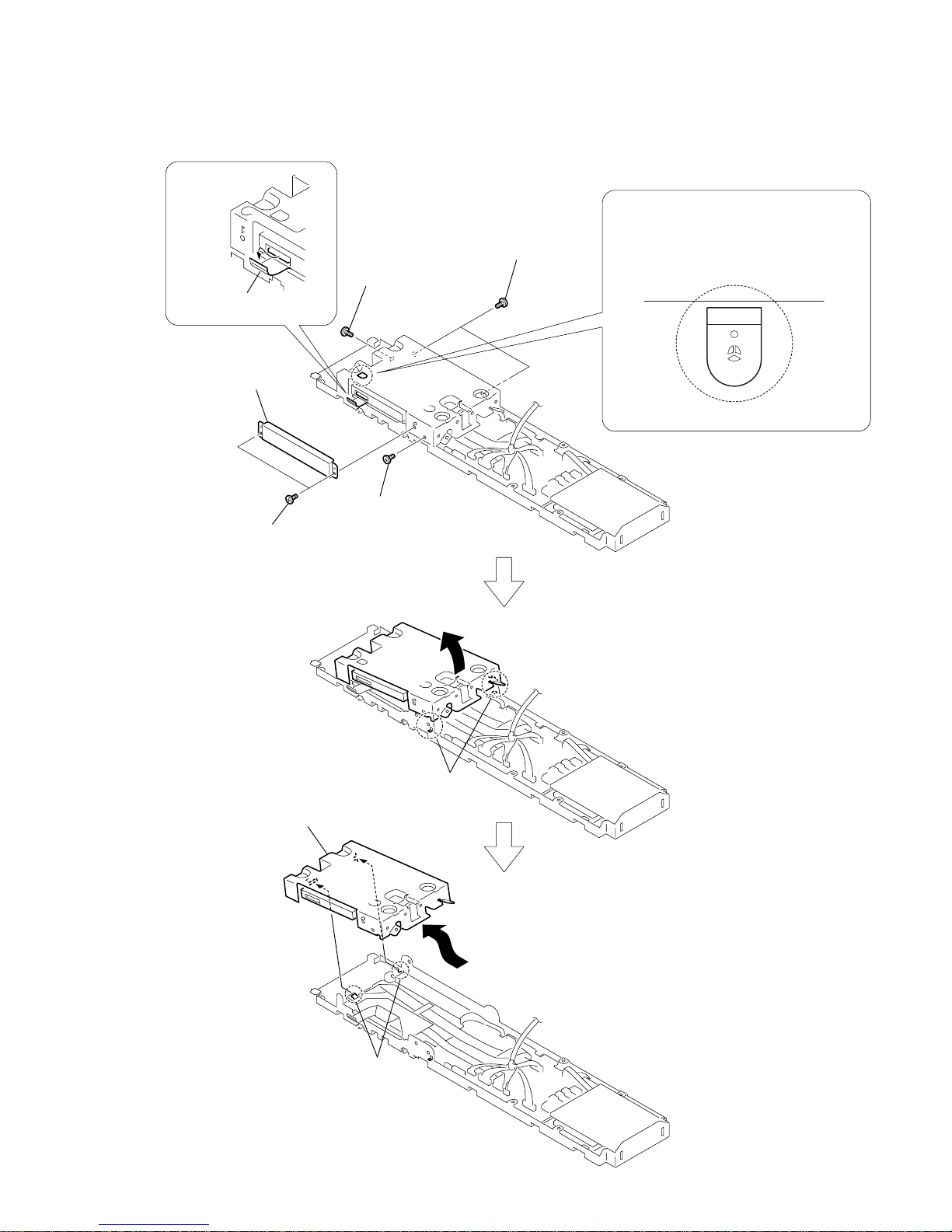
17
HCD-LF1H
When removing the mech module (AUR-M1),
create a solder bridge to prevent the optical
pick-up from breaking.
(Use a soldering iron with an antistatic earth.)
PRECAUTION DVD MECHANISM
[MECH MODULE (AUR-M1)]
DISASSEMBLY
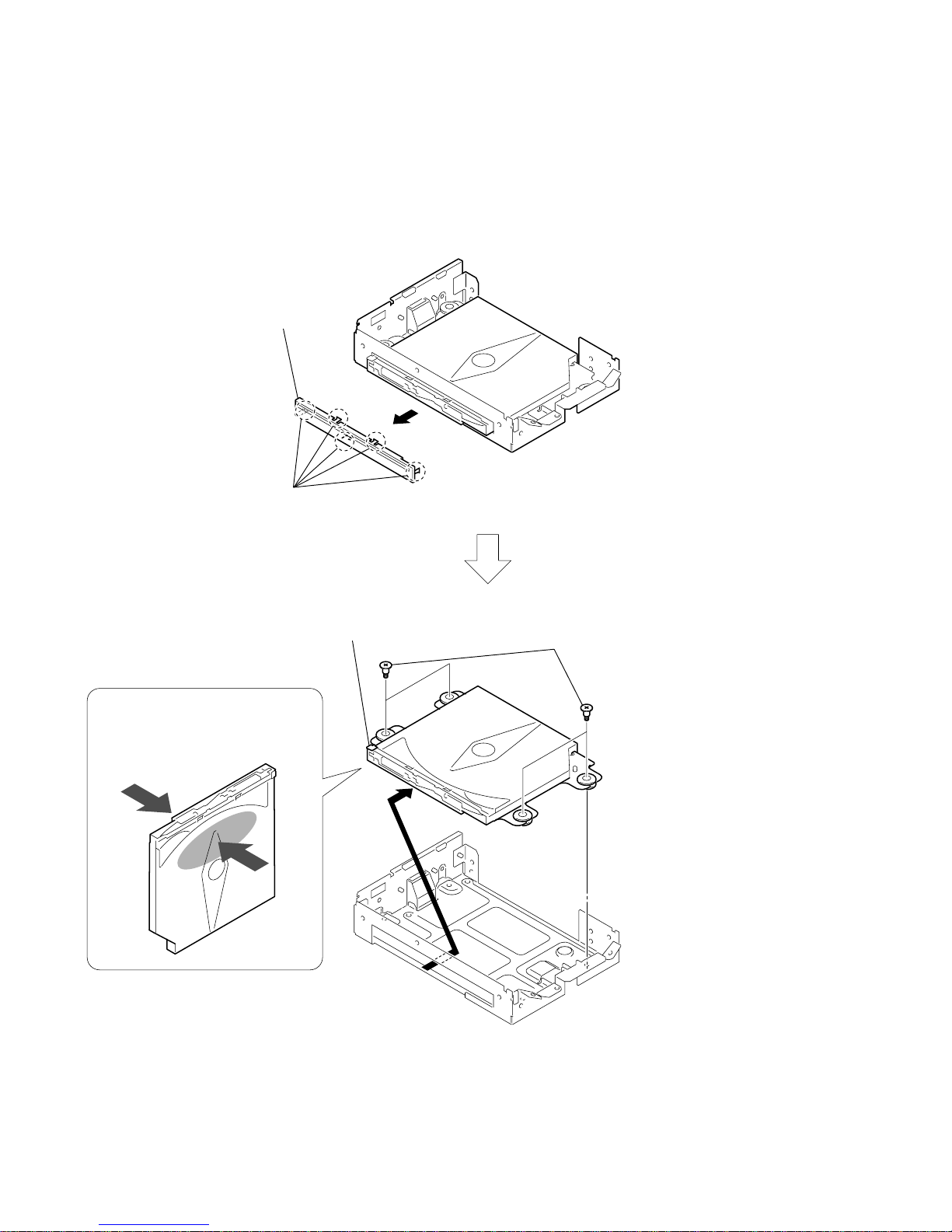
3
FFC 50p (160)
50core (CN101)
2
shield plate (CDM)
1
two screws
(+BVTP 3 × 6)
4
screw
(+BVTP 3 × 6)
6
two screws
(+BVTP 3 × 6)
5
screw
(+BVTT 3 × 8)
8
two claws
qa
mech module
(AUR-M1)
q;
two claws
9
7
3-9. DVD MECHANISM [MECH MODULE (AUR-M1)] SECTION-1
18
HCD-LF1H
1
five claws
4
2
panel (CDM)
3
four shafts (insulator)
5
mech module (AUR-M1),
bracket (CDM-L), etc.
Do not hold the A part of mech
module (AUR-M1). Doing so may
deform the module.
A
3-10. DVD MECHANISM [MECH MODULE (AUR-M1)] SECTION-2
19
HCD-LF1H
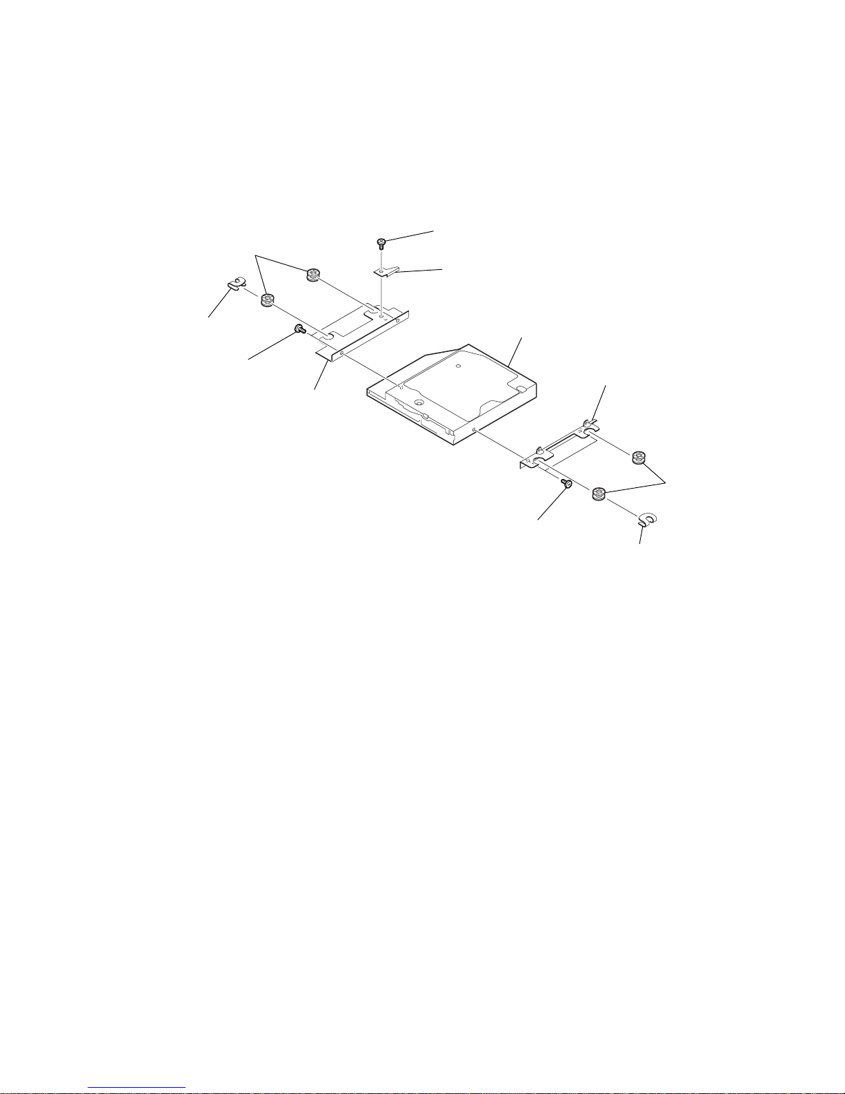
1
CDM ground plate
5
CDM ground plate
8
ground plate (function)
2
two insulator
s
6
two insulators
4
bracket (CDM-R)
0
bracket (CDM-L)
qa
mech module (AUR-M1)
3
two screws
(+B EG GRIP)
9
two screws
(+B EG GRIP)
7
screw
(+BVTP 3
×
6)
3-11. DVD MECHANISM [MECH MODULE (AUR-M1)] SECTION-3
20
HCD-LF1H
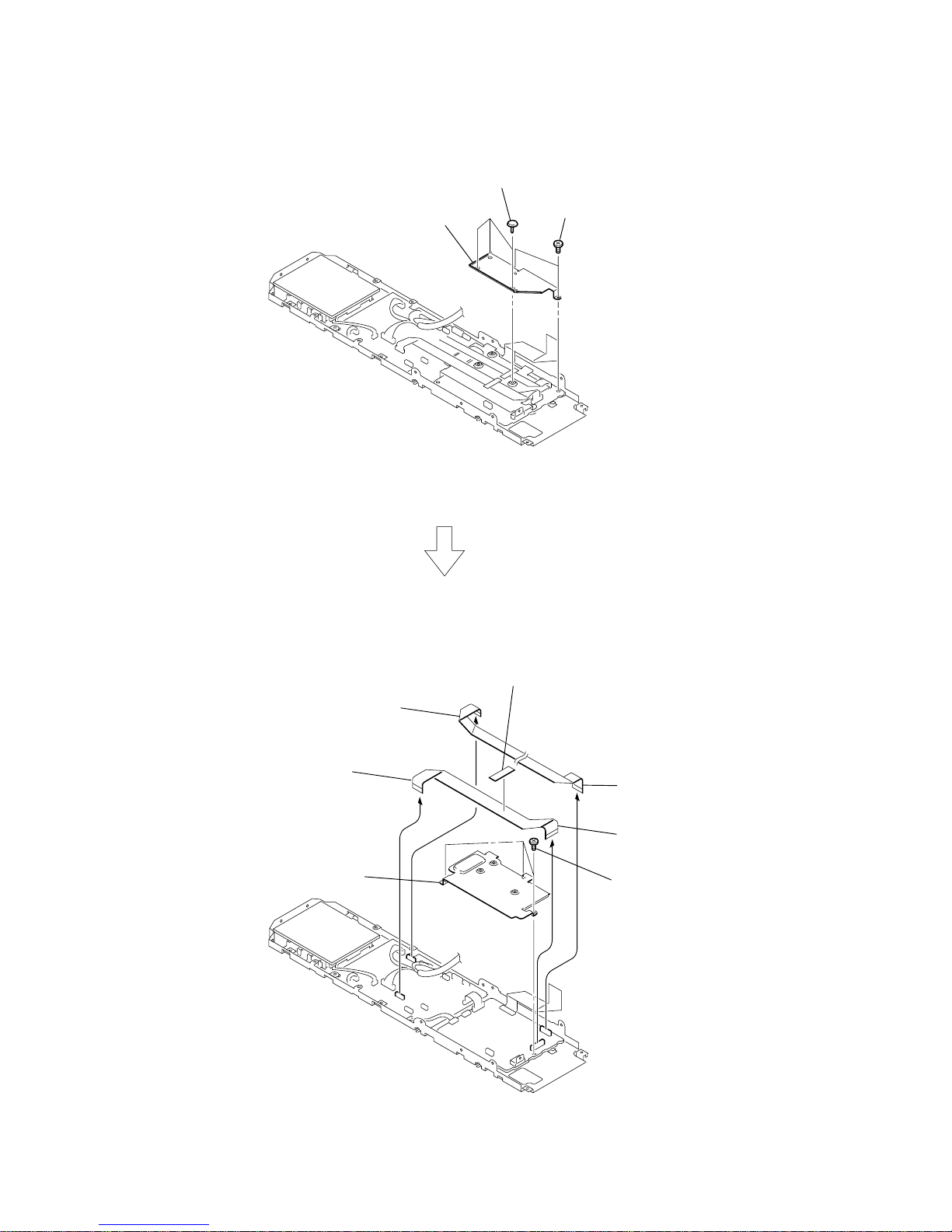
2
two screws
(+BVTP 3
×
6)
1
three nylon rivets (DIA. 3.5)
3
shield plate (FFC)
4
saranet cushion
8
FFC 21p (280)
21core (CN4502)
7
FFC 21p (280)
21core (CN501)
9
three screws
(+BVTP 3
×
6)
q;
shield plate (DMB)
6
FFC 15p (280)
15core (CN4301)
5
FFC 15p (280)
15core (CN601)
3-12. SHIELD PLATE (DMB)
21
HCD-LF1H
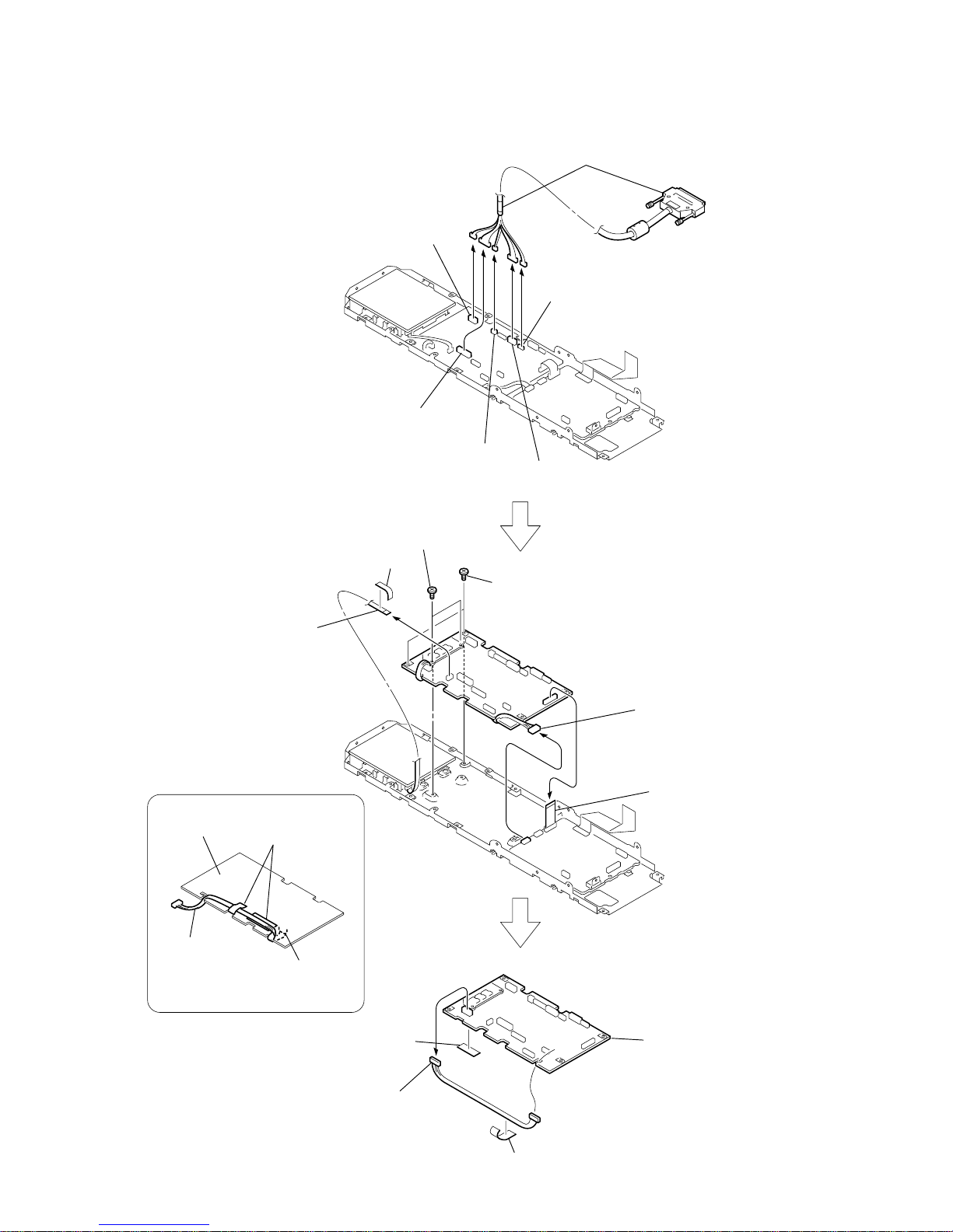
q;
two screws
(+BVTP 3
×
8)
qa
two screws
(+BVTP 3
×
6)
qs
connector
5P (CN601)
5
connector
8P (CN301)
1
connector
6P (CN101)
3
connector
2P (CN603)
2
connector
10P (CN602)
4
connector
7P (CN502)
qf
connector
5P (CN102)
qg
saranet
cushion
two saranet cushions
CN102
7
saranet cushion
qh
MAIN board
MAIN board
(side B)
qd
saranet cushion
harness
9
FFC 19p (40)
19core (CN302)
8
FFC 7p (100)
7core (CN308)
6
cable (system)
PRECAUTION DURING
HARNESS INSTALLATION
Route the harnesses as shown below.
3-13. MAIN BOARD
22
HCD-LF1H
3
connector
5P (CN601)
5
DMB14 board
2
six screws
(+BVTP 3 × 6)
1
FFC 19p (40)
19core (CN109)
4
FFC 50p (160)
50core (CN101)
3-14. DMB14 BOARD
23
HCD-LF1H
SECTION 4
TEST MODE
Note 1: Regarding the notification symbol “R”
Because the number of the operating buttons of this product
are limited, some operations require use of the operating
buttons of the remote commander, When a specif ic operation
requires use of the operating buttons of the remote
commander, “R” is added to the specific operating procedure
in this manual. Example MENU/NO “R” The MENU/NO
button of remote commander.
Note 2: Incorrect operations may be performed if the test mode is
not entered properly.
In this case, press the ?/1 button to turn the po wer of f, and
retry to enter the test mode.
3. Disc Slot Lock
The disc slot lock function for the antitheft of an demonstration
disc in the store is equipped.
Setting Procedure :
1. Press the ?/1 button to turn the set on.
2. Press the FUNCTION button to set DVD function.
3. Insert a disc.
4. Press the x button and the A button simultaneously for f ive
seconds.
5. The message “LOCKED” is displayed and the slot is locked.
Releasing Procedure :
1. Press the x button and the A button simultaneously for f ive
seconds, again.
2. The message “UNLOCKED” is displayed and the slot is
unlocked.
Note: When “LOCKED” is displayed, the slot lock is not released by
turning power on/off with the ?/1 button.
4. DVD Ship Mode
• Use this mode when returning the set to the customer after
repair.
Procedure:
1. Press the ?/1 button to turn the set on.
2. Press the FUNCTION button to set the function “DVD”.
3.
After all discs are removed, press two buttons
x , A ,
and
?/1
simultaneously.
4. After a message “MECHA LOCK” is displayed on the
fluorescent indicator tube, pull out the AC plug.
5.
To exit from this mode, press the ?/1 button to turn the set on.
5. AM Step Change
•A step of AM channels can be changed over between 9 kHz
and 10 kHz.
Procedure:
1. Press the ?/1 button to turn the set on.
2. Select the function “TUNER”, and press FUNCTION button
to select the BAND “AM”.
3. Press the ?/1 button to turn the set off.
4. Press two buttons FUNCTION and ?/1 simultaneously,
and the display of fluorescent indicator tube changes to “ AM
9 k STEP” or “AM 10 k STEP”, and thus the channel step is
changed over.
6. V olume T est Mode
Procedure:
1. Press the ?/1 button to turn the power on.
2. Press three buttons x , N and A simultaneously.
3. The message “Volume Max” is displayed, when press the
VOLUME + button.
The message “Volume Min” is displayed, when press the
VOLUME – button.
4.
To exit from this mode, press the ?/1 button to turn the set off.
7. Product Out
This mode moves the optical pick-up to the position durable to
vibration and clears all data including preset data stored in the RAM
to initial conditions. Use this mode when returning the set to the
customer after repair.
Procedure:
1. Press the ?/1 button to turn the power on.
2. Press the FUNCTION button to set the function “DVD”.
3.
After all discs are removed, p
ress three buttons VOLUME – ,
A and ?/1 simultaneously.
4. After the “STANDBY” blinking display finishes, the messa ge
“MECHA LOCK” is displayed on the fluorescent indicator
tube and the ship mode is set.
5. After a message “MECHA LOCK” is displayed on the
fluorescent indicator tube, pull out the AC plug.
1. Cold Reset
• The cold reset clears all data including preset data stored in
the RAM to initial conditions. Execute this mode when
returning the set to the customers.
Procedure:
1. Press the ?/1 button to turn the power on.
2. Press three buttons x , FUNCTION and ?/1 simulta-
neously.
3. When this button is operated, display as “COLD RESET” for
a while and all of the settings are reset.
2. Panel Test Mode
•This mode is used to check the software version, FL, LED
and KEY.
2-1. Display Test Mode
Procedure:
1. Press the ?/1 button to turn the power on.
2. Press three buttons x , VOLUME – and A simultaneously.
3. When the display test mode is activated, all segments and all
LEDs are turned on.
4. To exit from this mode, press three buttons x , VOLUME –
and A simultaneously.
2-2. V ersion T est Mode
Procedure:
1. When the panel test mode is activated, press the V OLUME +
button and the message “LFZ5” is displayed, the version test
mode is activated.
2. Whenever the VOLUME + button is pressed, the display
changes in the following order.
*1: LAT changes depending on destination.
3. Press the VOLUME – button and the date of the software
production is displayed.
4. Press the VOLUME – button again and the version is
displayed.
5. To exit from this mode, press three buttons x , VOLUME –
and A simultaneously.
2-3. Key Test Mode
Procedure:
1. When the panel test mode is activated, press the N button,
to select the key test mode.
2. To enter the KEY test mode, the fluorescent indicator displays
“K0”. Each time a button is pressed, “KEY” value increases.
However, once a button is pressed, it is no longer taken into
account. When all keys are pressed correctly , “K7” is displayed.
3. To exit from this mode, press three buttons x , VOLUME –
and A simultaneously.
“LFZ5” (Model name) t “LAT*1” (Destination) t MC t SYS
TM T DSP T TA T ST T CDMB T CDMA T DVD T UI
XM
24
HCD-LF1H
DVD SECTION
8. Mirror Time Check
[TEST DISC LIST]
Be sure to use the DVD disc that matches the signal standards of
your region.
HLX-513 (Part No.: J-2501-305-A)
HLX-A1 (Part No.: J-2501-307-A)
8-1. GENERAL DESCRIPTION
The Mirror Time allows you to make diagnosis and adjustment
simply by using the remote commander and monitor TV. The
instructions, diagnosis results, etc. are given on the on-screen display
(OSD).
Be sure to execute the Mirror time when a BU (Base Unit) is
replaced.
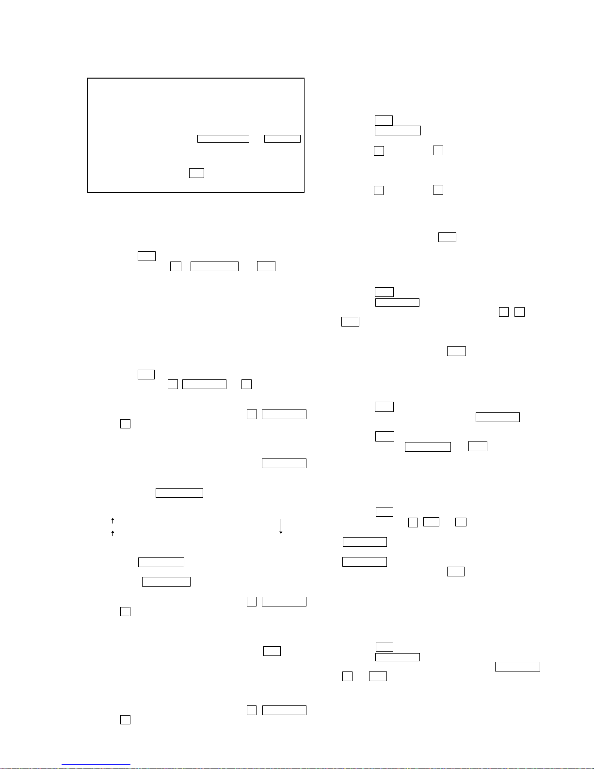
8-2. HOW TO ENTER TEST MODE
Press three buttons
x , A and VOLUME + simultaneously with
the DVD player.
The T est Mode starts, then the menu shown below will be displayed
on the TV screen.
The menu above is the Remocon Diagnosis Menu screen which
consists of five main functions. At the bottom of the menu screen,
the model name and IF-con version. To enter Mirror Time
Adjustment menu, press button 2 “R” on the remote commander
to enter Drive Manual Operation menu. To exit from the T est Mode,
press the power button on the remote commander.
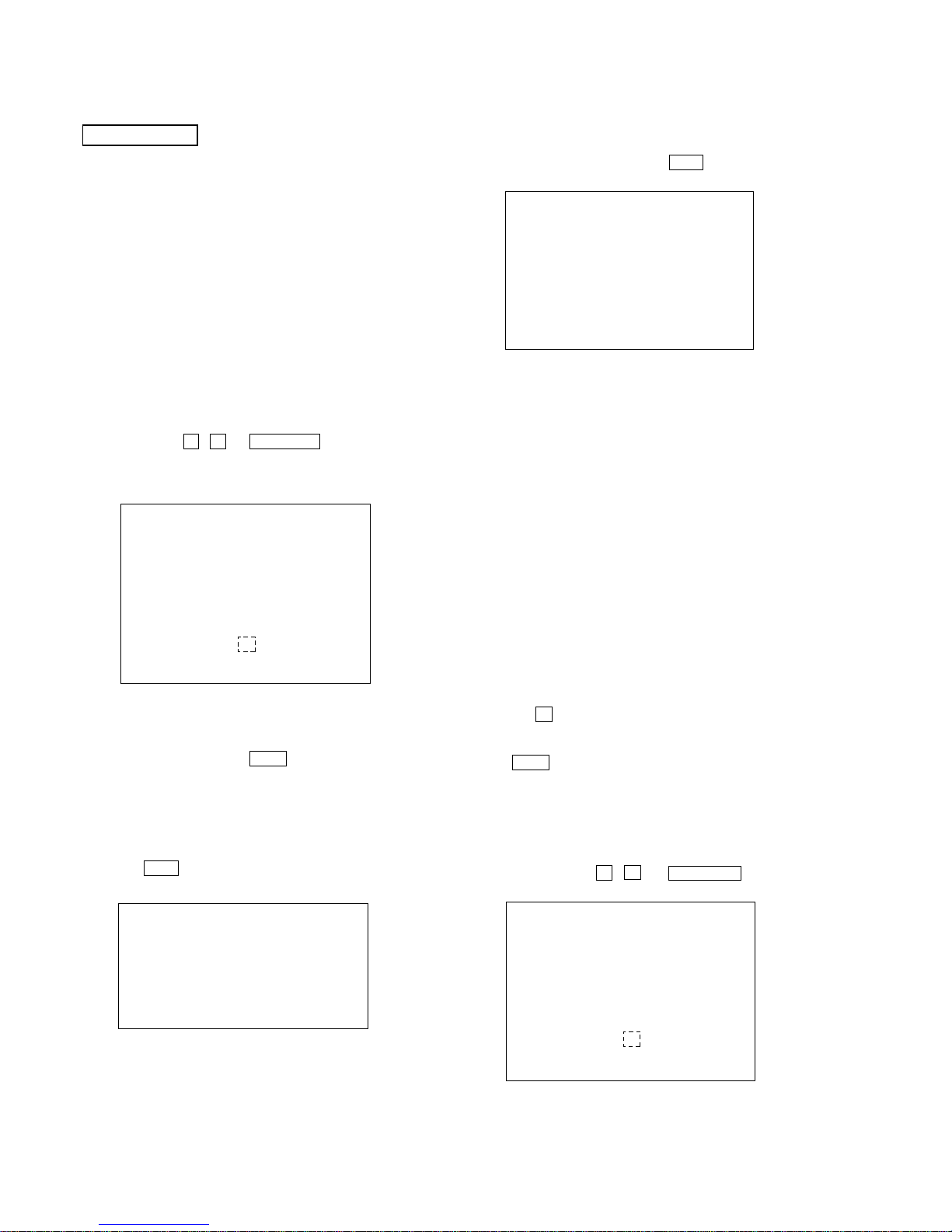
8-3. DRIVE MANUAL OPERATION
The Drive Manual Operation menu consists of fi ve main functions.
By pressing 2 “R” button on the remote commander in the Remocon
Diagnosis Menu, the screen will appear as shown.
Remocon Diagnosis Menu
0. External Chip Check
1. Servo Parameter Check
2. Drive Manual Operation
3. Emergency History
4. Version Information
Model Name : LFZ5_ XX
IF-con : V
Syscon : Ver.
er. XX.XX (XXXX)
X.XXX
*
1
*1: Changes depending on destination
Drive Manual Operation
1. Servo Control
2. Track/Layer Jump
3. Manual Adjustment
4. Tray Aging Mode
5. MIRR time Adjust
0. Return to Top Menu
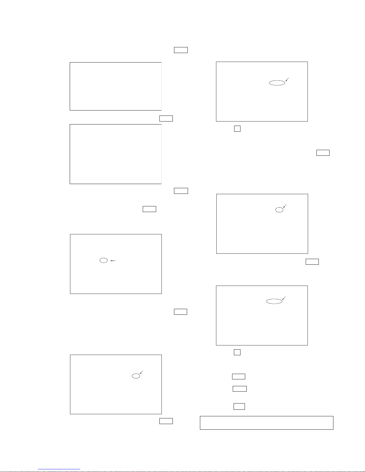
8-4. MIRROR TIME ADJUSTMENT
To enter Mirror Time Adjustment, press 5 “R” button on the remote
commander. The screen will appear as shown.
There are five main commands in the MIRR time Adjust menu as
shown in the figure above. The functions of each command are
described in the following page.
1. CD MIRR time Check
This command checks the Mirror time value for CD disc.
2. DVD MIRR time Check
This command checks the Mirror time value for DVD disc.
3. Threshold
This command displays the threshold value between CD and DVD
mirror time.
4. Save to EEPROM
This command saves an adjusted mirror time value to the EEPR OM.
5. Default set MIRR time
This command will set CD and DVD mirror time to firmware def ault
value.
[Open] / [Close]
Pressing the A button controls the tray for disc change during
mirror time adjustment.
[0] Return to previous menu
Press the 0 “R” button to return to previous menu.
8-4-1. EXECUTING MIRROR TIME ADJUSTMENT
In order to execute mirror time adjustment, the following standard
procedures must be followed.
(1)Press three buttons x , A and VOLUME +
simultaneously.
MIRR time Adjust Menu
1. CD MIRR time Check:
2. DVD MIRR time Check:
3. Threshold:
4. Save to EEPROM
5. Default set MIRR time
[Open] Tray open [Close] Tray close
[0] Return to previous menu
Remocon Diagnosis Menu
0. External Chip Check
1. Servo Parameter Check
2. Drive Manual Operation
3. Emergency History
4. Version information
Model Name :
IF-con : Ver. XX.XX (XXXX)
Syscon : Ver. X.XXX
: LFZ5_ XX
*
1
*1: Changes depending on destination
25
HCD-LF1H
(3)Select “5. MIRR time Adjust”, by pressing the 5 “R” b utton.
(4) Select “5. Default set MIRR time”, by pressing the 5 “R”
button.
(5)Select “3. Threshold”, by pressing the 3 “R” button.
(6) Confirm the number. If it is 35, go to next step. If it is any
other value, return to step (4).
(7)Insert Test Disc HLX-513.
(8) Select “2. DVD MIRR time Check”, by pressing the 2 “R”
button.
(9) Wait for HEX number to display.
(10) Confirm the number, if XX is 1F to 35, proceed with next
step. If no, return to step (8).
(11) Select “4. Save to EEPROM”, by pressing the 4 “R” b utton.
Drive Manual Operation
1. Servo Control
2. Track/Layer Jump
3. Manual Adjustment
4. Tray Aging Mode
5. MIRR time Adjust
0. Return to Top Menu
MIRR time Adjust Menu
1. CD MIRR time Check:
2. DVD MIRR time Check:
3. Threshold:
4. Save to EEPROM
5. Default set MIRR time
[Open] Tray open [Close] Tray close
[0] Return to previous menu
MIRR time Adjust Menu
1. CD MIRR time Check:
2. DVD MIRR time Check:
3. Threshold: 35
4. Save to EEPROM
5. Default set MIRR time
[Open] Tray open [Close] Tray close
[0] Return to previous menu
MIRR time Adjust Menu
1. CD MIRR time Check:
2. DVD MIRR time Check: XX XX
3. Threshold:
4. Save to EEPROM
5. Default set MIRR time
[Open] tray open [close] Tray close
[0] Return to previous menu
(12) Confirm the same values are displayed. If it is not same,
return to step (7).
(13) Press the A button to eject tray.
(14) Take out HLX-513 and insert Test Disc HLX-A1 into tray.
(15) Select “1. CD MIRR time check”, by pressing the 1 “R”
button.
(16) Wait for HEX number to display.
(17) Confirm the number, if YY is 42 to 79, proceed with next
step. If no, return to step (15).
(18) Select “4. Save to EEPR OM”, by pressing the 4 “R” button.
(19) Confirm the same values are displayed. If it is not the
same, return to step (15).
(20) Press the A button to eject tray.
(21) Remove Test Disc HLX-A1 from tray.
(22) Press the 0 “R” button to the Drive Manual Operation menu.
(23) Press the 0 “R” button to return to the Remocon Diagnosis
Menu.
(24) Press the ?/1 button to switch OFF set.
MIRR time Adjust Menu
1. CD MIRR time Check:
2. DVD MIRR time Check: XX XX
3. Threshold:
4. Save to EEPROM
5. Default set MIRR time
[Open] Tray open [close] Tray close
[0] Return to previous menu
MIRR time Adjust Menu
1. CD MIRR time Check: YY YY
2. DVD MIRR time Check: XX XX
3. Threshold:
4. Save to EEPROM
5. Default set MIRR time
[Open] Tray open [close] Tray close
[0] Return to previous menu
MIRR time Adjust Menu
1. CD MIRR time check: YY YY
2. DVD MIRR time check: XX XX
3. Threshold:
4. Save to EEPROM
5. Default set MIRR time
[Open] Tray open [close] Tray close
[0] Return to previous menu
(2) Select “2. Drive Manual Operation”, by pressing the 2 “R”
button.
For the sections 8-4-2. EXECUTING IOP MEASUREMENT and 8-5.
EMERGENCY HISTORY, refer to SUPPLEMENT-1 (9-887-283-8[])
Ver. 1.1
 Loading...