

Sony HCDLF-10 Service manual

HCD-LF10
SERVICE MANUAL
Ver. 1.0 2005.03
• HCD-LF10 is the super audio CD/DVD player section
in DAV-LF10.
This system incorporates with Dolby* Digital
and Dolby Pro Logic (II) adaptive matrix
surround decode r and the DTS** Digital
Surround System.
*Manufactured under license from Dolby
Laboratories.
“Dolby”, “Pro Logic”, and the double-D symbol are
trademarks of Dolby Laboratories.
**Manufact ur ed unde r license from Digital Theater
Systems, Inc.
“DTS”, “DTS-ES”, and “DTS Digital Surround”
are trademarks of Digital Theat er Systems, Inc.
US Model
E Model
Australian Model
Model Name Using Similar Mechanism NEW
DVD Mechanism Type CDM80AT-DVBU29T
Optical Traverse Unit Name DBU-3
SPECIFICATIONS
Super Audio CD/DVD system
Laser Semiconductor laser
(Super Audio CD/DVD: λ
= 650 nm)
(CD: λ = 780 nm)
Emission duration:
continuous
Signal format system
North America: NTSC
Other regions: NTSC, PAL
Frequency response (at 2 CH STER EO mode)
DVD (PCM): 2 Hz to 22
kHz (±1.0 dB)
CD: 2 Hz to 20 kHz (±1.0
dB)
Harmonic distortion Less than 0.03 %
Dimensions (approx.) 568 × 200 × 120 mm
Mass (approx.) 4.9 kg (10 lb 13 oz)
Design and specifications are subject to change
without notice.
3
/8 × 7 7/8 × 4 3/
(22
inches) (w/h/d) incl.
projecting parts
4
SUPER AUDIO CD/DVD PLAYER
9-879-564-01
2005C05-1
© 2005.03
Sony Corporation
Audio Group
Published by Sony Engineering Corporation
HCD-LF10
Notes on chip component replacement
• Never reuse a disconnected chip component.
• Notice that the minus side of a tantalum capacitor may be
damaged by heat.
Flexible Circuit Board Repairing
• Keep the temperature of the soldering iron around 270 ˚C
during repairing.
• Do not touch the soldering iron on the same conductor of the
circuit board (within 3 times).
• Be careful not to apply force on the conductor when soldering
or unsoldering.
CAUTION
Use of controls or adjustments or performance of procedures
other than those specified herein may result in hazardous radiation
exposure.
This appliance is
classified as a CLASS 1
LASER product. The
label is located on the
rear of the control unit.
SAFETY-RELATED COMPONENT WARNING!!
COMPONENTS IDENTIFIED BY MARK 0 OR DOTTED LINE
WITH MARK 0 ON THE SCHEMATIC DIAGRAMS AND IN
THE PARTS LIST ARE CRITICAL TO SAFE OPERATION.
REPLACE THESE COMPONENTS WITH SONY PARTS WHOSE
PART NUMBERS APPEAR AS SHOWN IN THIS MANUAL OR
IN SUPPLEMENTS PUBLISHED BY SONY.
2
This System Can Play the
Following Discs
Format of
discs
DVD VIDEO
Super Audio
CD
VIDEO CD
Format of
discs
Audio CD
CD-R/CD-RW
(audio data)
(MP3 files)
(JPEG files)
The “DVD VIDEO” logo is a trademark.
Note on PBC (Playback
Control) (VIDEO CDs)
This system conforms to Ver. 1.1 and Ver. 2.0 of
VIDEO CD standards. You can enjoy two kinds
of playback depending on the disc type.
Disc type You can
VIDEO CDs
without PBC
functions
(Ver. 1.1 discs)
VIDEO CDs
with PBC
functions
(Ver. 2.0 discs)
Disc logo
Disc logo
Enjoy video playback (moving
pictures) as well as music.
Play interactive software using
menu screens displayed on the
TV screen (PBC Playback), in
addition to the video playback
functions of Ver. 1.1 discs.
Moreover, you can play highresolution still pictures, if they
are included on the disc.
About Multi Session CD
• This system can play Multi Session CDs when
an MP3 audio track is contained in the f ir st
session. Any subsequent MP3 audio tr acks
recorded in later sessions can also be played
back.
• This system can play Multi Session CDs when
a JPEG image fil e is contained in the first
session. Any sub sequent JPEG image files
recorded in later sessions can also be played
back.
• If audio tr acks and images in music CD format
or video CD format are recorded in the first
session, only the first session will be played
back.
Region code
Your system has a region code printed on the
back of the unit and will only play DVDs labeled
with the same region code.
DVDs labeled will also play on this system.
ALL
If you try to play any other DVD, the message
[Playback prohibited by area limitations.] will
appear on the TV screen. Depending on the
DVD, no region code indication may be given
even though playing the DVD is prohibited by
area restrictions.
Examples of discs that the
system cannot play
The system cannot play the following discs:
• CD-ROMs (except for extension “.MP3,”
“.JPG,” or “.JPEG”)
• CD-Rs/CD-RWs other than those recorded in
the following formats:
− audio CD format
− video CD format
− MP3/JPEG format that conforms to
ISO9660* Level 1/Level 2, or it s ex ten d ed
format, Joliet
• Data part of CD-Extras
•
DVD-ROMs
•
DVD Audio discs
•
DVD-RAMs
•
Progressive JPEG file
A logical format of files and folders on CD-ROMs,
*
defined by ISO (International Organization for
standardization)
Do not load the following discs:
•
A DVD with a different region code.
•
A disc that is neither standard nor circular
(e.g., card, heart, or star shape).
•
A disc with paper or stickers on it.
A disc that has adhesiv e or cellophane ta pe still
•
left on it.
HCD-LF10
Notes about CD-R/CD-RW/
DVD-R/DVD-RW/DVD+R/
DVD+RW
In some cases, CD-R/CD-RW/DVD-R/DVDRW/DVD+R/DVD+RW cannot be played on
this player due to the recordin g quality or
physical condition of the disc, or the
characteristics of the recording devi ce and
authoring softwa re.
The disc wil l not pl ay if it has n ot been c orrectl y
finalized. For more information, see the
operating instruc ti ons for the recording device.
Note that discs created in the Packet Write
format cannot be played.
Music discs encoded w ith
copyright protec tion
tech nologies
This product is designed to playback discs that
conform to the Compact Disc (CD) standard.
Recently, various music discs encoded with
copyright protect ion technologies ar e marketed
by some record companies. Please be aware t hat
among those discs, there are some that do not
conform to the CD standard and may not be
playable by this produc t.
Note on DualDiscs
This product is designed to playback discs that
conform to the Compact Disc (CD) standard. A
DualDisc is a two sided disc product which
mates DVD recorded material on one side with
digital audio material on the other side. Please
be aware that the audio side of a DualDisc may
not play on this product because these discs do
not conform to th e CD standard.
“DualDisc” is a trademark of the Recording
Industry Association of Amer ic a (RIAA).
Note on playback operations
of DVDs and VIDEO CDs
Some playback operations of DVDs and VIDEO
CDs may be intentionally set by software
producers. Since this system plays DVDs and
VIDEO CDs according to the disc contents the
software producers designed, some playback
features may not be available. Also, refer to the
instructions supplied with the DVDs or VIDEO
CDs.
3

HCD-LF10
TABLE OF CONTENTS
1. SERVICING NOTES ............................................... 5
2. GENERAL ................................................................... 9
3. DISASSEMBLY
3-1. Disassembly Flow ........................................................... 11
3-2. Stand Section................................................................... 12
3-3. Cover (MAIN/CDM)....................................................... 12
3-4. Chassis Section................................................................ 13
3-5. D-LED Board .................................................................. 13
3-6. STBY KEY Board, EJECT KEY Board ......................... 14
3-7. Mechanism Deck (CDM80AT-DVBU29T) ..................... 14
3-8. DMB07 Board ................................................................. 15
3-9. DISPLAY Board .............................................................. 15
3-10. I/O Board ......................................................................... 16
3-11. DVD POWER Board....................................................... 16
3-12. Chassis (Top)................................................................... 17
3-13. Lever (Loading R/L)........................................................ 18
3-14. Disc Stop Lever, Disc Sensor Lever ................................ 19
3-15. Driver Board, Motor (Pulley) Assy (Loading) (M701) ... 19
3-16. RF Board ......................................................................... 20
3-17. Optical Traverse Unit (DBU-3)....................................... 20
3-18. Base Unit ......................................................................... 21
3-19. Lever (BU Lock) ............................................................. 21
3-20. Close Lever...................................................................... 22
3-21. Dir Lever, Gear (IDL-B).................................................. 22
3-22. Gear (IDL-C) ................................................................... 23
7. EXPLODED VIEWS
7-1. Stand Section................................................................... 87
7-2. Panel Section ................................................................... 88
7-3. Chassis Section................................................................ 89
7-4. Mechanism Deck Section-1 (CDM80AT-DVBU29T) .... 90
7-5. Mechanism Deck Section-2 (CDM80AT-DVBU29T) .... 91
7-6. Mechanism Deck Section-3 (CDM80AT-DVBU29T) .... 92
7-7. Mechanism Deck Section-4 (CDM80AT-DVBU29T) .... 93
8. ELECTRICAL PARTS LIST................................ 94
4. TEST MODE.............................................................. 24
5. ELECTRICAL ADJUSTMENTS ......................... 33
6. DIAGRAMS
6-1. Block Diagram – RF SERVO Section – .......................... 35
6-2. Block Diagram – VIDEO/MECHANISM Section –....... 36
6-3. Block Diagram – AUDIO Section –................................ 37
6-4. Block Diagram
– DISPLAY/POWER SUPPLY Section –....................... 38
6-5. Printed Wiring Board – RF Board – ................................ 40
6-6. Schematic Diagram – RF Board –................................... 41
6-7. Printed Wiring Board – DMB07 Board (Side A) – ......... 42
6-8. Printed Wiring Board – DMB07 Board (Side B) – ......... 43
6-9. Schematic Diagram – DMB07 Board (1/10) –................ 44
6-10. Schematic Diagram – DMB07 Board (2/10) –................ 45
6-11. Schematic Diagram – DMB07 Board (3/10) –................ 46
6-12. Schematic Diagram – DMB07 Board (4/10) –................ 47
6-13. Schematic Diagram – DMB07 Board (5/10) –................ 48
6-14. Schematic Diagram – DMB07 Board (6/10) –................ 49
6-15. Schematic Diagram – DMB07 Board (7/10) –................ 50
6-16. Schematic Diagram – DMB07 Board (8/10) –................ 51
6-17. Schematic Diagram – DMB07 Board (9/10) –................ 52
6-18. Schematic Diagram – DMB07 Board (10/10) –.............. 53
6-19. Printed Wiring Board – DRIVER Board –...................... 54
6-20. Schematic Diagram – DRIVER Board –......................... 54
6-21. Printed Wiring Boards
– DVD POWER/FAN CONTROL Boards – ................... 55
6-22. Schematic Diagram – DVD POWER Board (1/2) – ....... 56
6-23. Schematic Diagram
– DVD POWER (2/2)/FAN CONTROL Boards – .......... 57
6-24. Printed Wiring Board – I/O Board – ............................... 58
6-25. Schematic Diagram – I/O Board – .................................. 59
6-26. Printed Wiring Board – DISPLAY Board – .................... 60
6-27. Schematic Diagram – DISPLAY Board – ....................... 61
6-28. Printed Wiring Boards – KEY Section –......................... 62
6-29. Schematic Diagram – KEY Section – ............................. 63
4
SECTION 1
SERVICING NOTES
HCD-LF10
NOTES ON HANDLING THE OPTICAL TRAVERSE
UNIT OR BASE UNIT
The laser diode in the optical traverse unit block may suffer
electrostatic break-down because of the potential difference
generated by the charged electrostatic load, etc. on clothing and the
human body.
During repair, pay attention to electrostatic break-down and also
use the procedure in the printed matter which is included in the
repair parts.
The flexible board is easily damaged and should be handled with
care.
NOTES ON LASER DIODE EMISSION CHECK
The laser beam on this model is concentrated so as to be focused on
the disc reflective surface by the objecti ve lens in the optical traverse
unit. Therefore, when checking the laser diode emission, observe
from more than 30 cm away from the objective lens.
UNLEADED SOLDER
Boards requiring use of unleaded solder are printed with the leadfree mark (LF) indicating the solder contains no lead.
(Caution: Some printed circuit boards may not come printed with
the lead free mark due to their particular size)
: LEAD FREE MARK
Unleaded solder has the following characteristics.
• Unleaded solder melts at a temperature about 40 °C higher
than ordinary solder.
Ordinary soldering irons can be used but the iron tip has to be
applied to the solder joint for a slightly longer time.
Soldering irons using a temperature regulator should be set to
about 350 °C.
Caution: The printed pattern (copper foil) may peel away if
the heated tip is applied for too long, so be careful!
• Strong viscosity
Unleaded solder is more viscou-s (sticky, less prone to flow)
than ordinary solder so use caution not to let solder bridges
occur such as on IC pins, etc.
• Usable with ordinary solder
It is best to use only unleaded solder but unleaded solder may
also be added to ordinary solder.
RELEASING THE DISC SLOT LOCK
The disc slot lock function for the antitheft of an demonstration
disc in the store is equipped.
Releasing Procedure :
1. Press I/1 button to turn the power on.
2. Touch the [FUNCTION] sensor on the touch panel to select the
“DVD”.
3. Touch the x sensor on the touch panel and press the Z button
simultaneously and hold down until “Unlocked” displayed on
the fluorescent indicator tube (around 5 seconds).
Note: When “Locked” is displayed, the slot lock is not released by turning
power on/off with the I/1 button.
NOTE OF REPLACING THE DMB07 BOARD-1
When replacing the DMB07 board, since the adjustment value is
not set up correctly, “Drive Auto Adjustment” can’t be performed.
In this case, initialize memory in the following procedures.
Procedure:
1. Set the test mode. (See page 26)
2. Press the [2] key on the remote commander, and set the
“DRIVE MANUAL OPERATION”. (See page 28)
3. Press the [6] key on the remote commander, and set the “2-6,
Memory Check”. (See page 30)
4. Press the [CLEAR] ke y on the remote commander, and initialize
memory.
NOTE OF REPLACING THE DMB07 BOARD-2
New part of EEPROM (IC204, IC903) on the DMB07 board cannot
be used. Therefore, if the mounted DMB07 board is replaced,
exchange new EEPROM with that used before the replacement.
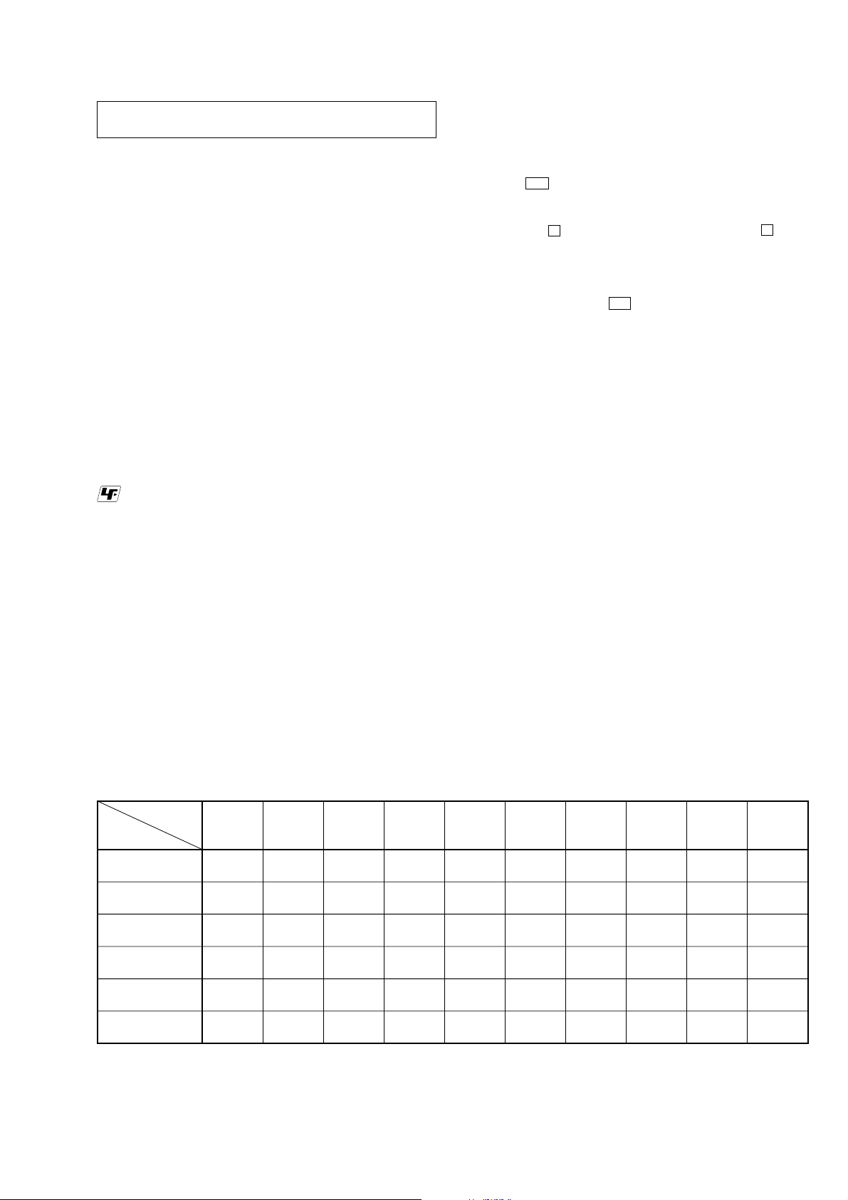
• The units that are required for the system operation check during repair service
Units required for
Unit.
need to
checking
Super audio CD/
DVD player : HCD-LF10
Sub woofer :
SA-WSLF10
Front speaker :
SS-TSL10
Center speaker :
SS-CTL10
Surround speaker :
SS-TSL11
Remote commander :
RM-SP320
*1 Only the defective unit. *2 Either one of them.
Units with a mark: The units that are required for the system operation check during repair service
However, there can be a case that some units of the system need to not be brought into repair shop depending on the unit. that became defective.
operation
Super audio CD/
DVD player :
check
HCD-LF10
a
a
a
a
Sub woofer :
SA-WSLF10
a
a
a
a
Front speaker :
SS-TSL10
a*1
a*2
Center
speaker :
SS-CTL10
a
Surround
speaker :
SS-TSL11
a*1
Remote
commander :
RM-SP320
a
a
a
a
a
Remote
sensor :
DIR-R4
Surround
amplifier :
TA-SB500WR
a
a
a
aaaa
IR transmitter :
DIR-T1
IR receiver :
DIR-R1
5

HCD-LF10
NOTE
*
The performance of the main unit can be connected with the remote controller, even if the panel is not connected.
CAUTION-1 (REPLACING THE TOUCH KEY BOARD)
CL404
CL403
CL402
TOUCH KEY BOARD
TOUCH PAD (B) BOARD
CL405
CL414
CL413
CL412
CL411
CL401
CL406
CL415
CL416
CL410
CL400
TOUCH PAD (A) BOARD
*
When the TOUCH KEY BOARD is replaced, wire the TOUCH KEY BOARD securely to
the TOUCH PAD (A) BOARD and TOUCH PAD (B) BOARD as shown in the figure.
6
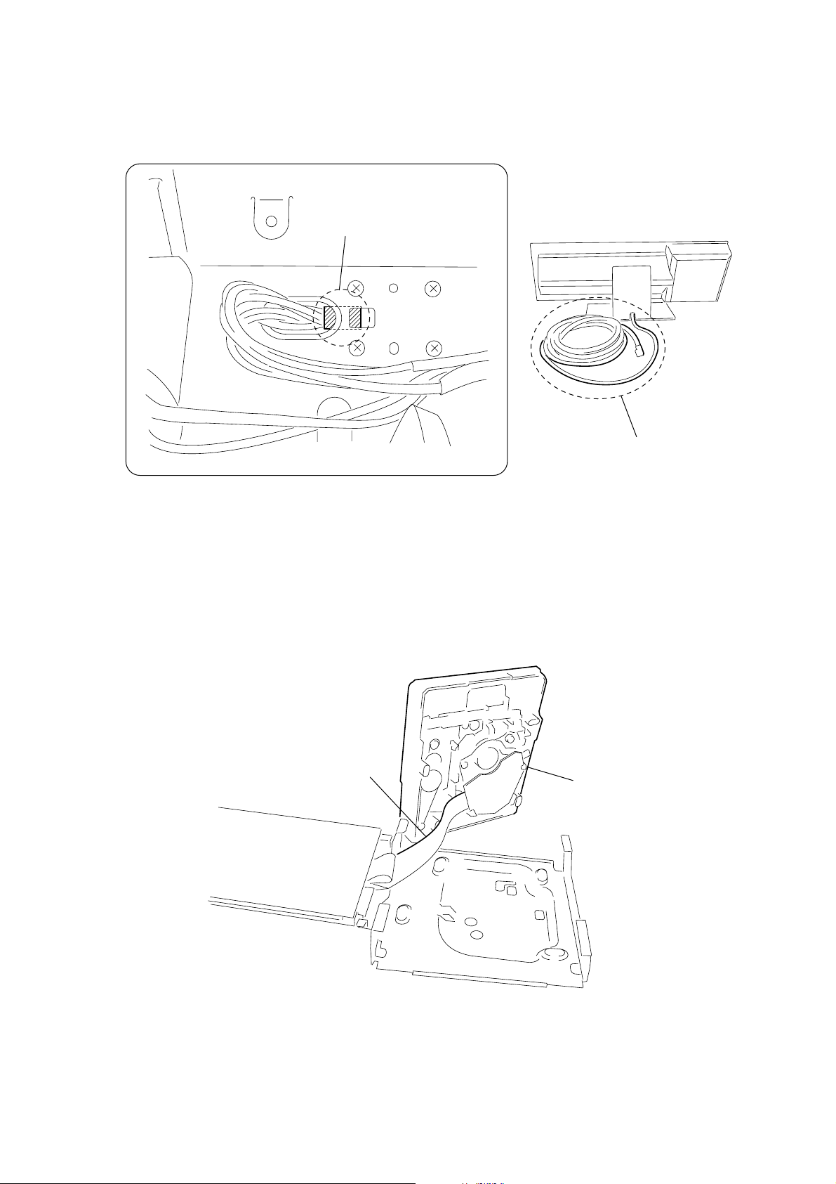
CAUTION-2 (REPLACING THE CONNECTING CORD)
*
When replacing the connecting cord, fix it at the position in the figure so that the copper conductor of
the cord and the steel plate contact (GND) adequately.
copper conductor of the cord
HCD-LF10
SERVICING POSITION-1 (MECHANISM DECK)
*
Connect the DVD POWER BOARD and the MECHANISM DECK with the extension cable,
and inspect the MECHANISM DECK.
extension cable
J-2501-103-A (29P/L300)
connecting cord
MECHANISM DECK
7

HCD-LF10
SERVICING POSITION-2 (DMB07 BOARD)
*
Connect the I/O BOARD and the DMB07 BOARD by using the three extension cables, and inspect the DMB07 BOARD.
extension cable
J-2501-199-A (25P/L300)
extension cable
J-2501-225-A (9P/L300)
extension cable
J-2501-243-A (17P/L300)
I/O BOARD
DMB07 BOARD
8

Front Panel
Top Panel
SECTION 2
GENERAL
HCD-LF10
This section is extracted from
instruction manual.
FUNCTION
+
VOL.
A DISC indicator
*
B Touc h Panel Sensor
C Front panel display
D DOLBY DIGITAL indicator
E DTS indicator
*
*
F DOLBY PRO LOGIC II indicator
G D.C.S. indicator
*Lights up when activated.
*
H [/1 (power) switch/standby indicator
I Disc slot
Z (eject)
J
*
9
HCD-LF10
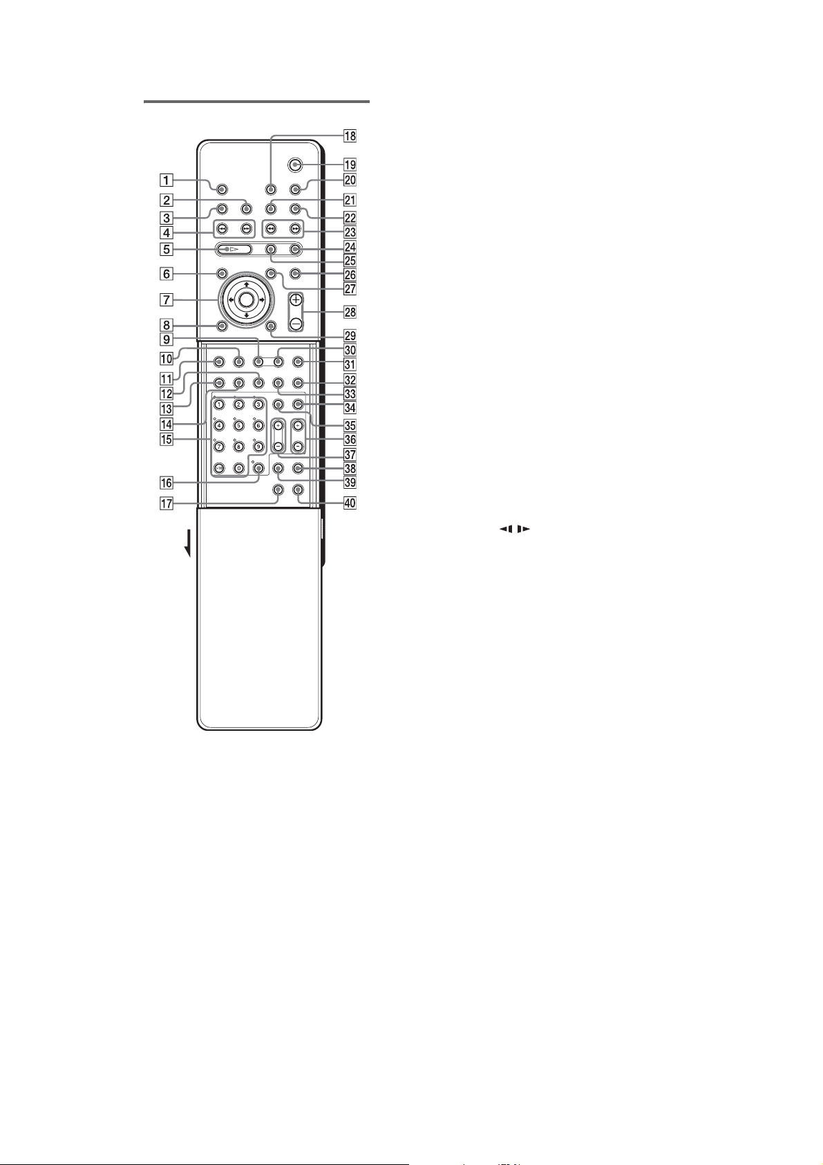
Remote
Open the cover.
Note
This remote control glo w s in the dark. However,
before glowing, the remote must be exposed to light for
a while.
AZ (eject)
B DISPLAY
C SLEEP
D ./>, PRESET −/+
E H (p lay)
The H button has a tactile dot.
F DVD TOP MENU/ALBUM−
G C/X/x/c/ENTER
The C/X/x/c has tactile dots.
H DVD DISPLAY
I AUTO FORMAT DIRECT
J DSGX
K DVD SETUP
L SUBTITLE
M AUDIO
The AUDIO button has a tactile dot.
N ANGLE
O Number buttons
The number 5 button has a tactile dot.
P ENTER
Q TUNER MENU
R TV [/1 (on/standby)
S "/1 (standby)
T SONY TV DIRECT (THEATRE SYNC)
U TUNER/BAND
V FUNCTION
W m/M/SLOW / TUNING−/+
X x (stop)
Y X (pause)
Z MUTING
wj DVD MENU/ALBUM+
wk VOL +/−
The VOL + button ha s a t ac til e dot.
wl O RETURN
e; MODE
ea NIGHT MODE
es PLAY MODE
ed REPEAT
ef TV
eg TV/VIDEO
eh TV CH +/−
The TV CH + button has a tacti le dot.
ej TV VOL +/−
ek AMP MENU
el CLEAR
r; FM MODE
*Use the tacti le dot as a refere nce when operati ng the
system.
*
*
*
*
*
*
10

3-1. DISASSEMBLY FLOW
•This set can be disassembled in the order shown below.
•The dotted square with arrow (
completed.
SET
3-2.
STAND ASSY
(Page 12)
3-3.
COVER (MAIN/CDM)
(Page 12)
CHASSIS SECTION
3-4.
(Page 13)
) prompts you to move to the next job when all of the works within the dotted square ( ) are
HCD-LF10
SECTION 3
DISASSEMBLY
3-7.
MECHANISM DECK
CDM80AT-DVBU29T)
(
(Page 14)
3-12
. CHASSIS (TOP)
(Page 17)
. LEVER (LOADING R / L)
3-13
(Page 18)
. DMB07 BOARD
3-8
(Page 15)
. I/O BOARD
3-10
(Page 16)
3-15
. DRIVER BOARD,
MOTOR (PULLEY) ASSY
(LOADING) (M701)
(Page 19)
. DISC STOP LEVER,
3-14
DISC SENSOR LEVER
(Page 19)
. DISPLAY BOARD
3-9
(Page 15)
. DVD POWER BOARD
3-11
(Page 16)
3-16
. RF BOARD
(Page 20)
3-17
. OPTICAL TRAVERSE
UNIT (DBU-3)
(Page 20)
. D-LED BOARD
3-5
(Page 13)
6. STBY KEY BOARD,
3-
EJECT KEY BOARD
(Page 14)
3-18
. BASE UNIT
(Page 21)
3-19
. LEVER (BU LOCK)
(Page 21)
3-20
. CLOSE LEVER
(Page 22)
3-21
. DIR LEVER,
GEAR (IDL-B)
(Page 22)
3-22
. GEAR (IDL-C)
(Page 23)
11
HCD-LF10
)
Note: Follow the disassembly procedure in the numerical order given.
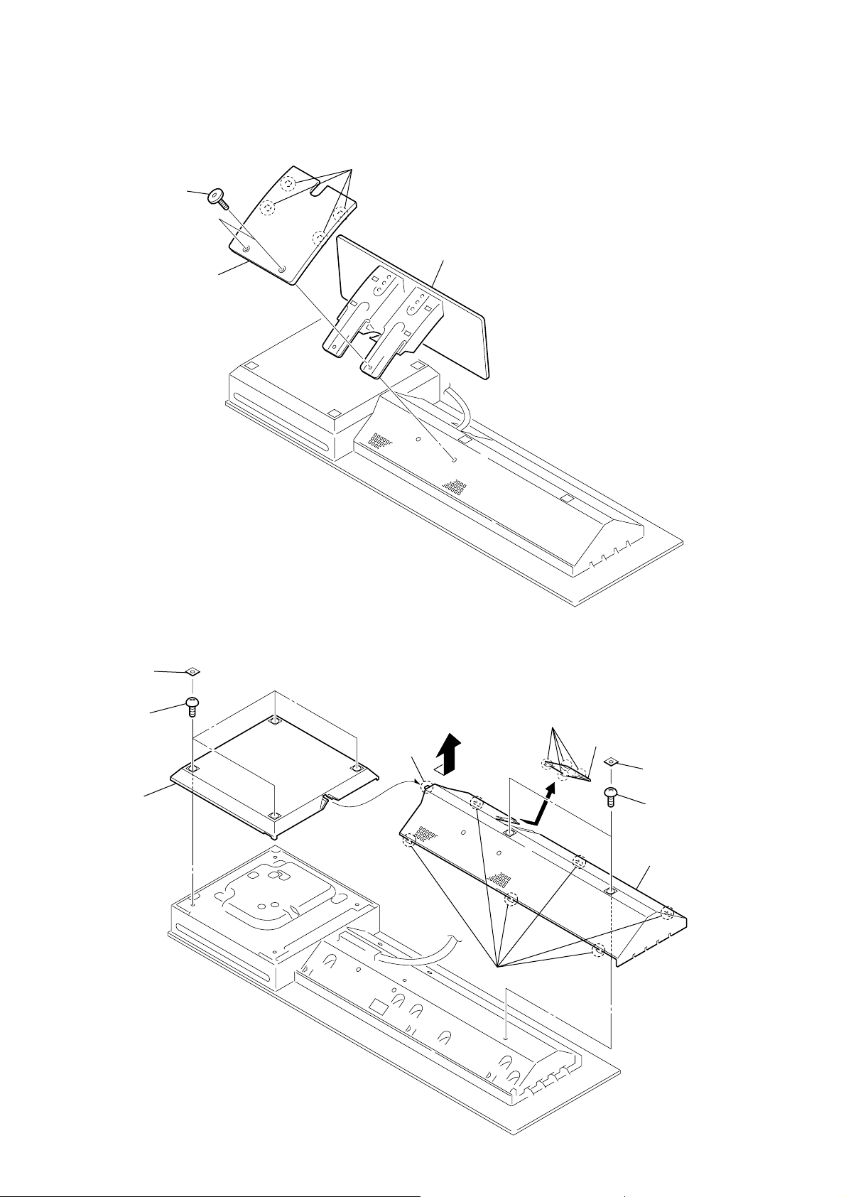
3-2. STAND ASSY
1
two screws
3
cover (rear)
2
four claws
4
stand assy
3-3. COVER (MAIN/CDM)
8
four covers (SH)
9
four screws
(BVTP 3 × 8)
q;
cover (CDM)
4
hook
3
six claws
5
four claws
6
cover (SYS)
1
two covers (SH
2
two screws
(BVTP 3 × 8)
7
cover (MAIN)
12

3-4. CHASSIS SECTION
)
6
four screws
(BVTP 2.6 )
q;
chassis section
3
two screws
(BVTP 3
5
bracket (A)
×
8)
1
two screws
(BVTP 3
HCD-LF10
×
8)
2
side panel (CDM)
4
screw
(BVTP 3
×
6)
7
five screws
(BVTP 3
×
8)
8
four dowels
3-5. D-LED BOARD
4
connector
(CN309)
5
D-LED board
3
two dowels
2
indicator (DISC)
1
hook
9
wire (flat type)
(18 core) (CN401
13

HCD-LF10
)
3-6. STBY KEY BOARD, EJECT KEY BOARD
6
two hooks
qa
escutcheon assy
3
connector
(CN310)
q;
EJECT KEY board
8
two screws
(BVTP 2.6)
7
bracket (escutcheon)
5
two dowels
2
connector
(CN311)
9
STBY KEY board
1
two screws
(BVTP 2.6)
4
two screws
(BVTP 2.6)
3-7. MECHANISM DECK (CDM80AT-DVBU29T)
6
connector
(CN701)
5
wire (flat type) (29 core)
(CN002)
2
enclosure (CFU)
(US model)
1
two screws
(BVTP 3
×
8)
1
two screws
(BVTP 3
(US model)
3
reinforcement
(TPK1)
×
8)
7
mechanism deck
(CDM80AT-DVBU29T
14
4
four screws
(BVTP 3 × 10)
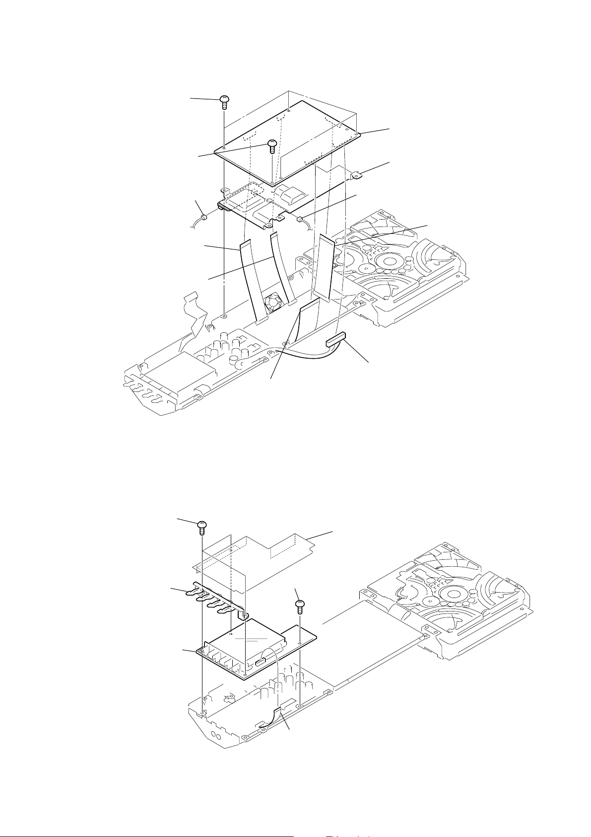
3-8. DMB07 BOARD
)
1
four screws
(BVTT 3 × 6)
2
screw
(BVTP 3 × 8)
9
(CN401)
3
wire (flat type) (17 core)
(CN105)
4
wire (flat type) (9 core)
(CN101)
connector
9
connector
(CN402)
8
DMB07 board
q;
heat sink (DMB)
6
HCD-LF10
wire (flat type) (25 core
(CN107)
3-9. DISPLAY BOARD
1
three screws
(BVTP 3
2
indicator (FUNC)
6
DISPLAY board
×
8)
5
wire (flat type) (29 core)
(CN501)
4
screw
(BVTP 3
3
enclosure (FL)
(US model)
×
8)
7
connector
(CN102)
5
wire (flat type) (12 core)
(CN451)
15

HCD-LF10
3-10. I/O BOARD
1
wire (flat type) (17 core)
(CN201)
5
four screws
(BVTP 3
4
connector
(CN203)
7
I/O board
2
wire (flat type) (9 core)
(CN204)
×
8)
4
connector
(CN202)
3
wire (flat type) (25 core)
(CN101)
6
clamp (L35)
4
connector
(CN103)
4
connector
(CN102)
3-11. DVD POWER BOARD
1
wire (flat type) (18 core)
(CN304)
3
connector
(CN305)
3
connector
(CN302)
2
wire (flat type)
(12 core) (CN303)
3
connector
(CN301)
3
connector
(CN902)
4
four screws
(BVTP 3
5
DVD POWER board
3
×
connector
8)
(CN910)
3
connector
(CN901)
16

3-12. CHASSIS (TOP)
)
3
5
chassis (top)
4
two screws
(P 2
×
10)
three screws
(BVTP 2.6)
1
screw
(BVTP 2.6)
2
lever (CL UP2
HCD-LF10
17

HCD-LF10
3-13. LEVER (LOADING R/L)
5
lever (loading R)
1
spt-T (loading R) spr-T (loading L)
4
two hooks
1
2
two hooks
3
lever (loading L)
18
PRECAUTION DURING LEVER (LOADING R / L) INSTALLATION
Align the horizontal position.
lever (loading L)
Install the
both levers so that they move symmetrically.
lever (loading R)
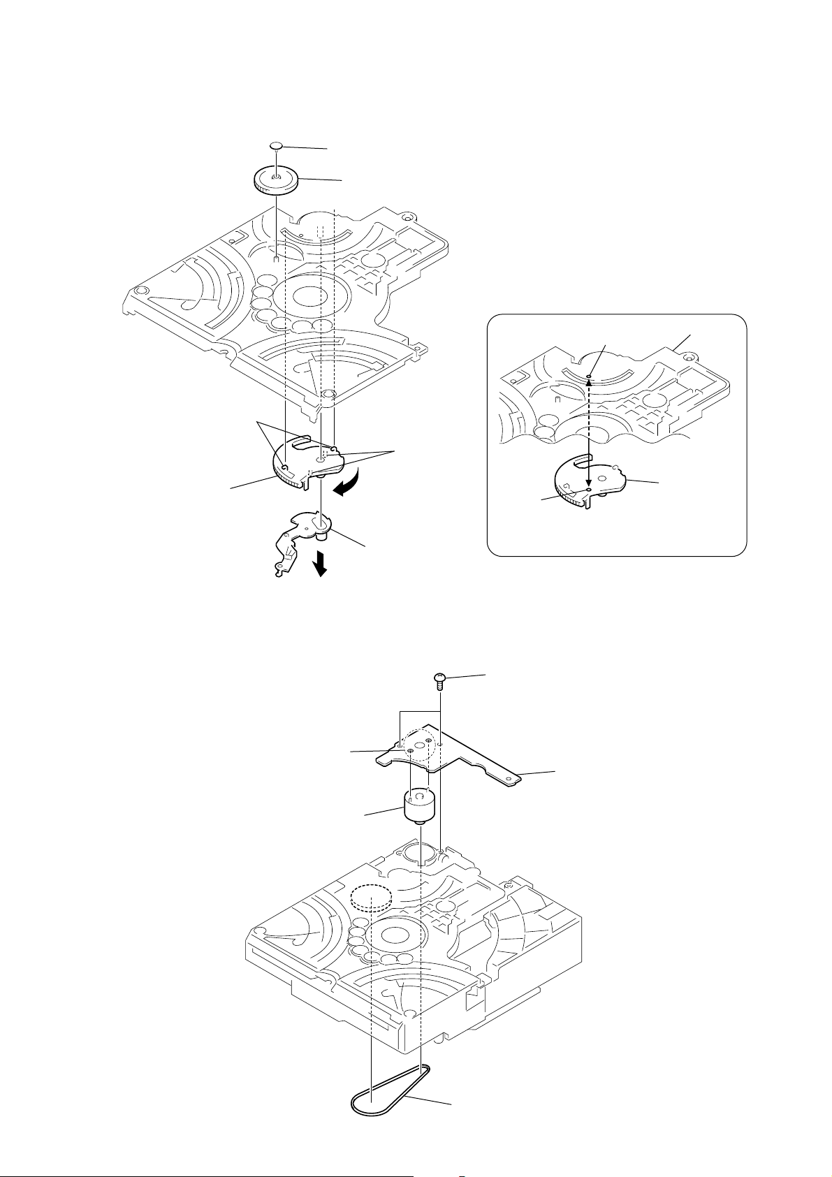
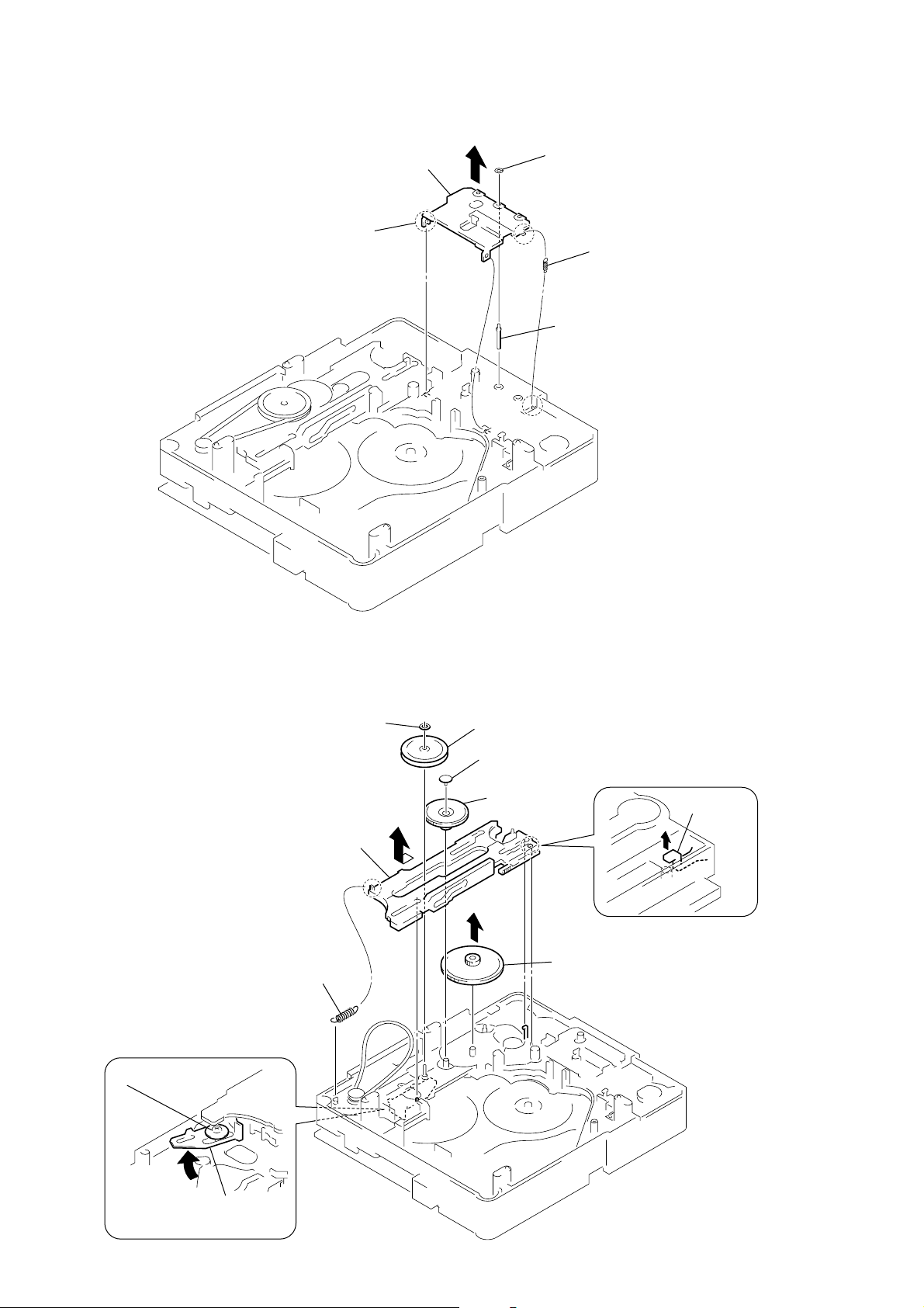
3-14. DISC STOP LEVER, DISC SENSOR LEVER
d
1
gear (cap)
2
gear (IDL L)
HCD-LF10
PRECAUTION DURING DISC STOP LEVER INSTALLATION
5
two hooks
3
two claws
6
disc stop lever
4
disc sensor lever
hole
Install the disc stop lever so that the both holes
are aligned.
3-15. DRIVER BOARD, MOTOR (PULLEY) ASSY (LOADING) (M701)
2
two screws
(BVTP 2.6)
hole
chassis (top)
disc stop lever
3
Remove soldering
from the two points.
4
motor (pully) assy
(loading) (M701)
5
DRIVER boar
1
belt (MOT)
19

HCD-LF10
d
3-16. RF BOARD
3
flexible board
(CN001)
4
RF board
1
claw
2
motor flexible boar
(CN003)
3-17. OPTICAL TRAVERSE UNIT (DBU-3)
3
6
optical traverse unit
(DBU-3)
2
step screw (M)
4
insulator
two insulators (RB)
1
two step screws (M)
5
tension coil spring (H-1)
20

3-18. BASE UNIT
)
5
three hooks
4
6
lever (BU lock)
1
gear (cap)
2
gear (BU lock)
3
floating screw
(PTPWHM 2.6)
6
base unit
4
floating screw
(PTPWHM 2.6)
3
coil spring (holder down A
HCD-LF10
3-19. LEVER (BU LOCK)
2
lever (CL UP2)
1
screw
(BVTP 2.6)
5
floating screw
(PTPWHM 2.6)
21
HCD-LF10
3-20. CLOSE LEVER
3
5
claw
close lever
1
washer (3-1-0.4)
2
close lever spring
4
shaft disc stop
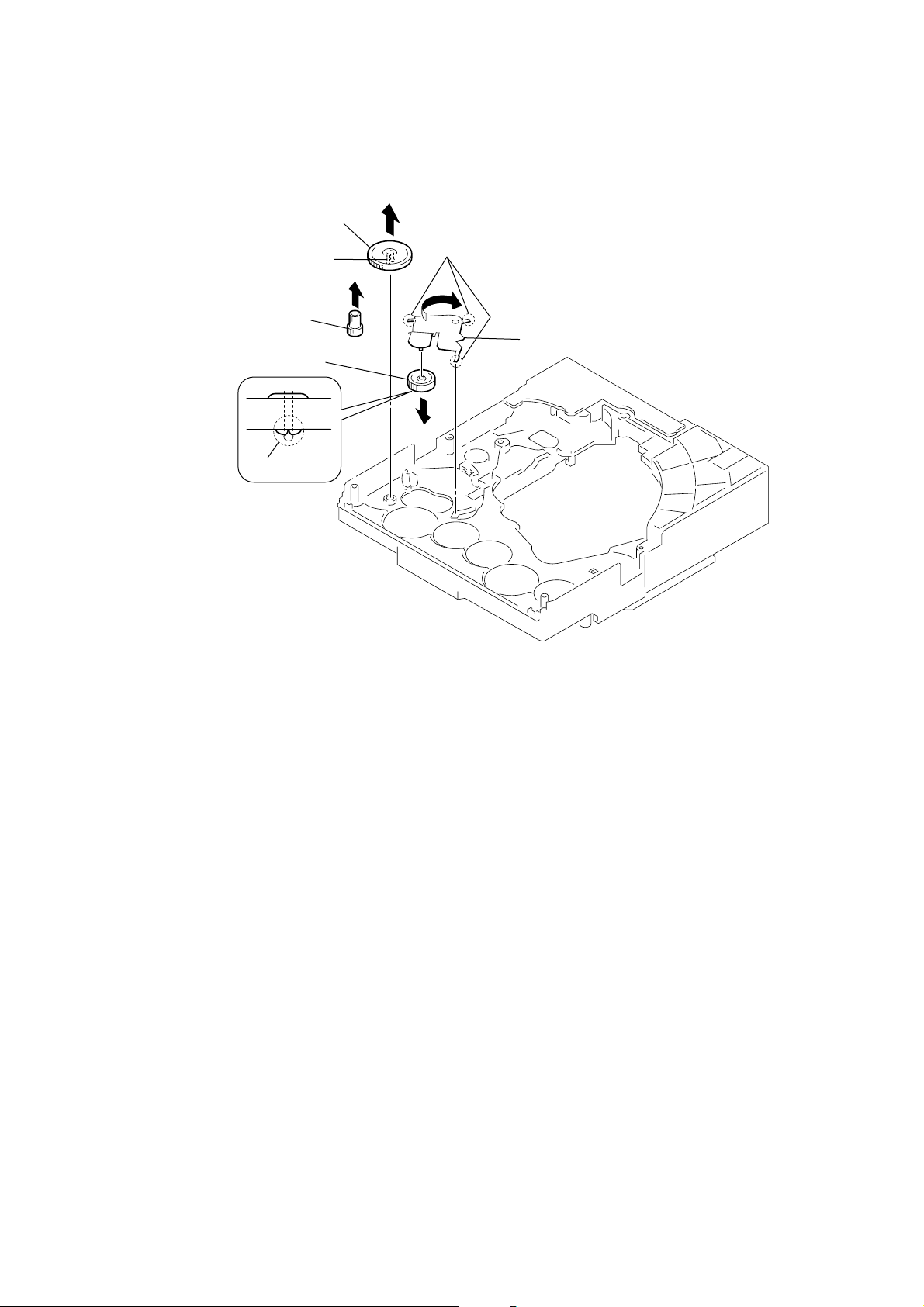
3-21. DIR LEVER, GEAR (IDL-B)
2
1
tension coil spring (DIR)
6
Loosen the screw.
nylon washer 1.7
9
DIR lever
3
puley (gear )
4
gear (cap)
5
gear (IDL-A)
q;
gear (IDL-B)
8
stopper
22
7
Hold the release lever
and change the direction.
3-22. GEAR (IDL-C)
1
3
gear (IDL-D)
2
two claws
gear (IDL-F)
7
gear (IDL-C)
6
claw
4
three hooks
5
gear loading lever
HCD-LF10
23

HCD-LF10
SECTION 4
TEST MODE
Note 1: Regarding the notification symbol “R”.
Because the number of the operating buttons of this product
are limited, some operations require use of the operating buttons
of the remote commander (RM-SP320 supplied with the
product). When a specific operation requires use of the
operating buttons of the remote commander (RM-SP320), “R”
is added to the specific operating procedure in this manual.
Example. MENU/NO “R” :
The [MENU/NO] button of remote commander.
Note 2: Incorrect operations may be performed if the test mode is not
entered properly.
In this case, press the I/1 button to turn the power off, and
retry to enter the test mode.
1. COLD RESET
The cold reset clears all data including preset data stored in the
RAM to initial conditions. Execute this mode when returning the
set to the customers.
Procedure:
1. Press the I/1 button to turn the power on.
2. Touch the VOL − sensor on the touch panel and press the Z
button simultaneously for several seconds.
3. The “Cold Reset” display appears for a while, then “Standby”
display blinks, and finally turn the power off (standby mode).
2. DISC SLOT LOCK
The disc slot lock function for the antitheft of an demonstration
disc in the store is equipped.
Procedure :
1. Press the I/1 button to turn the power on.
2. Press the FUNCTION “R” button or touch the FUNCTION sensor
on the touch panel to select the “DVD”.
3. Insert a disc.
4. Touch the x sensor on the touch panel and press the Z button
simultaneously for several seconds.
5. The “Locked” display appears for a while and disc cannot be
removed any more even if the Z button is pressed.
*To release this mode, repeat the above operation. The
“Unlocked” display appears and the disc slot lock mode is
canceled.
Note: When “Locked” is displayed, the slot lock is not released by turning
power on/off with the I/1 button.
3. DVD SHIP MODE
This mode moves the optical pick-up to the position durable to
vibration. Use this mode when returning the set to the customer
after repair.
Procedure:
1. Press the I/1 button to turn the power on.
2. Press the FUNCTION “R” button or touch the FUNCTION sensor
on the touch panel to select the “DVD”.
3. Remove a disc.
4. Touch the . sensor on the touch panel and press the Z button
simultaneously for several seconds with no disc inserted in
the drive.
5. The “Mecha Lock” display appears for a while, then “Standby”
display blinks, and finally turn the power off (standby mode).
* If this operation is performed while the disc is inserted, “Not
In Use” display appears.
4. TEST MODE
The test mode is prepared in this product. Refer to item 5. TEST
MODE IN for the procedure how to enter the test mode, and to item
6. TEST MODE Advance to advance the test mode menu.
Note: Be sure to turn off the power of the product after the following test
mode is completed.
TEST MODE MENU
Version Information
Key Test Mode
Display Test Mode
AMP Test Volume
Repeat Limit
DVD Service
Product Out
VACS ON/OFF
VACS Display
Touch Sensor Test
5. TEST MODE IN
1. When the product is already disassembled for repair, enter the
test mode as follows. Press the TEST MODE key (S301) inside
the product to enter the TEST MODE.
2. To enter the TEST MODE by the external operation (i.e., to
enter the TEST MODE after the product is already reassembled upon completion of repair), touch the seven sensors
on the touch panel in turn while pressing the Z button.
Note1: There is a set to which TEST MODE key (S301) is not mounted.
The set in which TEST MODE key (S301) is not mounted enters
the test mode by the external operation.
Moreover, there is an item with the description operated as follo ws
with the TEST MODE key (S301). The item is done by other
operations that have been described.
Note2: Using the TEST MODE IN function by the external operation is
available only for the equipment with the production number of
10450 and onward.
6. TEST MODE MENU ADVANCE
1. Press the TEST MODE key (S301) inside the product to
advance the TEST MODE MENU.
2. If the product is already set in the TEST MODE, the MENU
can be advanced by pressing the RETURN O “R” button.
Note: The MENU advance function using the remote control is available
only for the equipment with the production number of 10450 and
onward.
7. VERSION INFORMATION
Procedure:
1. Press the TEST MODE key (S301) inside the product or the
RETURN O “R” button.
2. The version is displayed in order of GC, STR, DVD, and
AREA.
24

HCD-LF10
8. KEY TEST MODE
Procedure:
1. Press the TEST MODE key (S301) inside the product or the
RETURN O “R” button.
2. The message “Key Test” is displayed.
3. Press the ENTER “R” button while the message “Key Test” is
being displayed. The message “Key Number 0” is displayed.
4. Each time a button on the set is pressed, the key number
increases.
5. The key test reaches its end when the “Key Number 2” is
displayed.
9. DISPLAY TEST MODE
Procedure:
1. Press the TEST MODE key (S301) inside the product or the
RETURN O “R” button.
2. The message “Display Test” is displayed.
3. Press the ENTER “R” button while the message “Display T est”
is being displayed.
4. Each time the TEST MODE key (S301) is pressed, the display
changes as follows. (This operation cannot be performed
externally)
All lights off t All lights on t Displays light on alternately
Illuminate alternately t All lights off
10. AMP TEST VOLUME
1. Press the TEST MODE key (S301) inside the product or the
RETURN O “R” button.
2. The message “Amp Test Volume” is displayed.
3. Press the ENTER “R” button while the message “Amp Test
Volume” is being displayed. The message “Amp Test Volume
Min” is displayed.
4. Each time the b “R” button is pressed, display changes as
follows:
Min(0) t Center (20) t Max (40) t Min (0)
14. VACS ON/OFF
1. Press the TEST MODE key (S301) inside the product or the
RETURN O “R” button.
2. The message “VACS ON/OFF” is displayed.
3. Press the ENTER “R” button while the message “VACS On/
Off” is being displayed. Either the message “VACS On” or
“VACS Off” is displayed.
4. Select either “VACS On” or “VACS Off” by the b “R” key.
5. After this check is completed, make sure to return the set to
“VACS On”.
15. VACS DISPLAY
1. Press the TEST MODE key (S301) inside the product or the
RETURN O “R” button.
2. The message “VACS Display” is displayed.
3. Press the ENTER “R” button while the message “V A CS Display”
is being displayed. “VACS * ” is displayed, where “*”
represents numeric value.
4. If “V A CS Off” is selected in step 14, “VACS Off” is displayed.
16. TOUCH SENSOR TEST
1. Press the TEST MODE key (S301) inside the product or the
RETURN O “R” button.
2. “QT SCAN” is displayed with the numbers of 0 to 9 after the
character.
3. Touch the sensor on the touch panel while a number in the
range of 0 to 9 is being displayed. The asterisk (*) is displayed
next to the corresponding number when a touch sensor is
touched.
11.REPEAT LIMIT
Procedure:
1. Press the TEST MODE key (S301) inside the product or the
RETURN O “R” button.
2. The message “Repeat Limit” is displayed.
3. Press the ENTER “R” button while the message “Repeat Limit”
is being displayed. The message “Repeat Limit Command Out”
is displayed.
4. Press the ENTER “R” button while the message “Repeat Limit
Command Out” is being displayed. The message “LIMIT
OFF” is displayed.
12. DVD SERVICE
Procedure:
1. Press the TEST MODE key (S301) inside the product or the
RETURN O “R” button.
2. The message “DVD Service” is displayed.
3. Press the ENTER “R” button while the message “DVD Service”
is being displayed. The message “DVD Service ON” is
displayed.
4. Press the ENTER “R” button w hile the message “DVD Service
On” is being displayed. After a while, the message “SER VICE
IN” is displayed, and “TEST MODE MENU” is then displayed
on the on-screen display (OSD).
13. PRODUCT OUT
This function is not available outside the factory. Please skip over
this mode.
25

HCD-LF10
DVD SECTION
GENERAL DESCRIPTION
The T est Mode allows you to make diagnosis and adjustment easil y
using the remote commander and monitor TV. The instructions,
diagnostic results, etc. are given on the on-screen display (OSD).
TEST DISC LIST
Use the following test disc on test mode.
TDV-520CSO (DVD-SL): PART No. J-2501-236-A
LUV-P01 (CD): PART No. 4-999-032-01
TDV-540C (DVD-DL): PART No. J-2501-235-A
Note: Do not use exiting test disc for DVD.
STARTING TEST MODE
1. Press the TEST MODE key (S301) inside the product or the
RETURN O “R” button.
2. The message “DVD Service” is displayed.
3. Press the ENTER “R” button while the message “DVD Service”
is being displayed. The message “DVD Service On” is
displayed.
4. Press the ENTER “R” button w hile the message “D VD Service
On” is being displayed. After a while, the message “SER VICE
IN” is displayed, and displays the Test Mode Menu on the
monitor screen as follows. (At the bottom of the menu screen,
the model name and revision number are displayed)
Test Mode Menu
0. Syscon Diagnosis
1. Drive Auto Adjustment
2. Drive Manual Operation
3. Mecha Aging
4. Emergency History
5. Mecha Error History
6. Version Information
7. Video Level Adjustment
Exit: POWER Key
Model :DAV-LF10
Revision :x.xx
OPERATING TEST MODE
0. SYSCON DIAGNOSIS
The same contents as board detail check by serial interface can be
checked from the remote commander operation.
On the Test Mode Menu screen, press 0 “R” key on the remote
commander, and the following Check Menu will be displayed.
### Syscon Diagnosis ###
Check Menu
0. Quit
1. All
2. Version
3. EEPROM
4. GPIO
5. SD Bus
6. Video
0-0. Quit
Quit the Syscon Diagnosis and return to the Test Mode Menu.
0-1. All (All items continuous check)
This menu checks all diagnostic items continuously. Normally, all
items are checked successively one after another automatically
unless an error is found, but at a certain item that requires judgment
through a visual check to the result, the following screen is displayed
for the key entry.
Example display
### Syscon Diagnosis ###
Diag All Check
No.2 Version
2-2. Version
ROM Revision = X.XX
5. To execute each function, select the desired menu and press
its number on the remote commander.
6. To release from test mode, press the I/1 button and turn the
power off.
Press NEXT Key to Continue
Press PREV Key to Repeat
For the ROM Check, the check sum calculated by the Syscon is
output, and therefore you must compare it with the specified value
for confirmation.
Following the message, press the > “R” button to go to the next
item, or press the .“R” button to repeat the same operation again.
To quit the diagnosis and return to Check Menu screen, press the
RETURN O “R” key on the remote commander to display Check
Menu.
26

HCD-LF10
General Description of Checking Method
Selecting 2 and subsequent items calls the submenu screen of each
item. And selecting 2 and subsequent items executes respective
menus and outputs the results.
For the contents of each submenu, see “Check Items List” as below .
Check Items List:
0-2. Version
0-2-1. All
0-2-2. Revision
0-2-3. ROM Check Sum
0-2-4. Model Type
0-2-5. Region
0-3. EEPROM Check
0-3-1. Sampling Check
0-3-2. Detail Check
0-4. GP I/O Check
0-5. SD Bus Check
0-6. Video Check
0-2. Version
0-2-2. Revision
The revision number of ROM (IC205) that the program
for the DVD system processor (IC207) is stored.
0-2-3. ROM Check Sum
The check sum of ROM (IC205) that the program for the
DVD system processor (IC207) is stored.
(4 digits hexadecimal number)
0-2-4. Model Type
Model name is displayed. (DAV-LF10)
0-2-5. Region
Model destination code is displayed. (2 digits number)
0-3. EEPROM Check
0-3-1. Sampling Check
EEPROM check at every 64 words.
It compares read data with write data of each address.
When there are discrepancies between two data, it displays
error.
0-3-2. Detail Check
EEPROM check at every 1 word.
It compares read data with write data of each address.
When there are discrepancies between two data, it displays
error.
0-4. GP I/O Check
Pull up/down setting check of the DVD system processor (IC207)
pin 150, 151 and 154 (for clock setting port).
0-5. SD Bus Check
SD bus data check between DVD decoder (IC701) and D-RAM
(IC706).
0-6. Video Check
Output the color bars for video level adjustment.
1. DRIVE AUTO ADJUSTMENT
On the Test Mode Menu screen, press the 1 “R” key on the remote
commander, and the Adjustment Menu will be displayed.
## Drive Auto Adjustment ##
Adjustment Menu
0. ALL
1. DVD-SL
2. CD
3. DVD-DL
Exit: RETURN
Normally, 0 “R” is selected to adjust DVD (single layer), CD and
DVD (dual layer) in this order . But, individual items can be adjusted
for the case where adjustment is suspended due to an error. In this
mode, the adjustment can be made easily through the operation
following the message displayed on the screen.
The disc used for adjustment must be the one specified for
adjustment.
1-0. ALL
Press the 0 “R” key on the remote commander, and the servo set
data in EEPROM will be initialized. Then, 1. DVD-SL disc, 2. CD
disc and 3. DVD-DL disc are adjusted in this order.
Each time one disc was adjusted, it is ejected. Replace it with the
specified disc following the message. You can f inish the adjustment
by pressing the RETURN O “R” button on the remote commander.
Note: During adjustment of each disc, the measurement for disc type
judgment is made. As automatic adjustment does not judge the disc
type unlike conventional models, take care not to insert wrong type
discs. Also, do not give a shock during adjustment.
1-1. DVD-SL (single layer)
Press the 1 “R” key on the remote commander and insert a DVD
single layer disc following the message. Then the adjustment will
be made through the steps below , then adjusted values will be written
to the EEPROM.
DVD Single Layer Disc Adjustment Steps:
1. Sled tilt reset
2. Disc check memory SL
3. Wait 300 msec
4. Set disc type SL
5. LD on
6. Spindle start
7. Wait 1 sec
8. Focus servo on 0
9. Auto track offset adjust
10. CLVA on
11. Wait 500 msec
12. Tracking on
13. Wait 1 sec
14. Sled on
15. Check CLV on
16. Auto LFO adjust
17. Auto focus offset adjust
18. Auto tilt position adjust
19. Auto focus gain adjust
20. Auto focus offset adjust
27

HCD-LF10
21. EQ boost adjust
22. Auto loop filter offset adjust
23. Auto track gain adjust
Search Check
24. 32 track jump forward
25. 32 track jump reverse
26. 500 track jump forward
27. 500 track jump reverse
28. All servo stop
29. EEP copy loop filter offset
1-2. CD
Press the 2 “R” key on the remote commander and insert a CD disc
following the message. Then the adjustment will be made through
the steps below , then adjusted values will be written to the EEPR OM.
CD Adjustment Steps
1. Sled tilt rest
2. Disc check memory CD
3. Wait 500 msec
4. Set disc type CD
5. LD on
6. Spindle start
7. Wait 500 msec
8. Focus servo on 0
9. Auto track offset adjust
10. CLVA on
11. Wait 500 msec
12. Tracking on
13. (TC display start)
14. Wait 1 sec
15. Jitter display start
16. Sled ON
17. Check CLV on
18. Auto loop filter offset adjust
19. Auto focus offset adjust
20. Auto focus gain adjust
21. Auto focus offset adjust
22. EQ boost adjust
23. Auto LFO Adjust
24. Auto track gain adjust
Search Check
25. 32Tj forward
26. 32Tj reverse
27. 500Tj forward
28. 500Tj reverse
29. All servo stop
1-3. DVD-DL (dual layer)
Press the 3 “R” key on the remote commander and insert a DVD
dual layer disc following the message. Then the adjustment will be
made through the steps below, then adjusted values will be written
to the EEPROM.
DVD Dual Layer Disc Adjustment Steps:
1. Sled tilt reset
2. Disc check memory DL
3. Wait 500 msec
4. Set disc type DL
5. LD on
6. Spindle start
7. Wait 1 sec
Layer 1 Adjust
8. Focus servo on 0
9. Auto track offset adjust
10. CLVA on
11. Wait 500 msec
12. Tracking on
13. Wait 500 msec
14. Sled on
15. Check CLV lock
16. Auto loop filter offset adjust, Auto focus adjust
17. Auto focus gain adjust
18. Auto focus offset adjust
19. EQ boost adjust
20. Auto loop filter offset adjust
21. Auto Track Gain Adjust
Search Check
22. 32 track jump forward
23. 32 track jump reverse
24. 500 track jump forward
25. 500 track jump reverse
Layer 0 Adjust
26. Focus jump (L1 t L0)
27. Auto track offset adjust L0
28. CLVA on
29. Wait 500 msec
30. Tracking on
31. Wait 500 msec
32. Sled on
33. Check CLV lock
34. Auto focus filter offset adjust
35. Auto Focus Adjust
36. Auto focus gain adjust
37. Auto focus offset adjust
38. EQ boost adjust
39. Auto Loop Filter Offset
40. Auto track gain adjust
Search Check
41. 32 track jump forward
42. 32 track jump reverse
43. 500 track jump forward
44. 500 track jump reverse
Layer Jump Check
45. Layer jump (L0 t L1)
46. Layer jump (L1 t L0)
47. All servo stop
2. DRIVE MANUAL OPERATION
Note: This mode is used for design, and not used in service fundamentally.
On the Test Mode Menu screen, press the 2 “R” key on the remote
commander, and the Operation Menu will be displayed. For the
manual operation, each servo on/off control and adjustment can be
executed manually.
## Drive Manual Operation ##
Operation Menu
1. Disc Type
2. Servo Control
3. Track/Layer Jump
4. Non EEPROM Write Adjust
5. EEPROM Write Adjust
6. Memory Check
7. Disc Check Memory
8. Error Rate Display
9. SACD Water Mark
Exit: RETURN
In using the manual operation menu, take care of the following
points. These commands do not provide protection, thus requiring
correct operation. The sector address or time code field is displayed
when a disc is loaded.
28

HCD-LF10
Servo Control
1.LD off R.Sled FWD
2.Focus off L.Sled REV
3.SPDL off U.Sled Reset
4.CLVA off D.Sled Limit
5.Trk. off
6.Sled off
7.Fcs.Srch off
0.All Servo Off
Exit: RETURN
Note:
1. Set correctly the disc type to be used on the Disc
Type screen.
2. In case of an alarm, immediately touch the x sensor
on the touch panel to stop the servo operation, and
press the I/1 button to turn the power off.
Basic operation:
(controllable from front panel or remote commander)
I/1 : Power off (release the test mode)
x : Servo stop
Z : Stop and eject/Loading
RETURN O “R” : Return to Operation Menu or Test
Mode Menu
.“R” , > “R” : Transition between sub modes of
menu
1 “R” to 9 “R” , 0 “R” : Selection of menu items
Cursor V “R” / v “R” : Increase/Decrease in manually
adjusted value
2-1. Disc Type
Disc Type
Disc Type Select
1. Disc Type Auto Check
2. Set Disc Type DVD
3. Set Disc Type CD
4. Set Disc Type Hybrid
FZC Count : The number of times which focus zero cross points
of each layer when lens down.
PI Reference : The average of PI reference voltage. (hexadecimal
number)
PI Peak : PI peak level voltage. It performs only when disc
type judgment is successful. (he xadecimal number)
2-1-2. Disc Type DVD
It sets up so that it may judge as a disc type of specification of the
disc with which the set was inserted.
[1]: DVD single layer disc (12 cm)
[2]: DVD dual layer disc (0 layer, 12 cm)
[3]: DVD dual layer disc (1 layer, 12 cm)
[4]: DVD-RW disc (12 cm)
[5]: DVD single layer disc (8 cm)
[6]: DVD dual layer disc (0 layer, 8 cm)
[7]: DVD dual layer disc (1 layer, 8 cm)
[8]: DVD-RW disc (8 cm)
2-1-3. Disc Type CD
It sets up so that it may judge as a disc type of specification of the
disc with which the set was inserted.
[1]: CD disc (normal speed, 12 cm)
[2]: CD disc (double speed, 12 cm)
[3]: CD disc (normal speed, 8 cm)
[4]: CD disc (double speed, 8 cm)
[5]: CD-RW disc (normal speed, 12 cm)
[6]: CD-RW disc (double speed, 12 cm)
[7]: CD-RW disc (normal speed, 8 cm)
[8]: CD-RW disc (double speed, 8 cm)
2-1-1. Disc Type Auto Check
1) Press the 1 “R” key on the remote commander to display the
Disc T ype Auto Check screen.
2) Insert a disc and press the ENTER “R” key on the remote commander.
3) It judges the type of inserted disc automatically and displays
the disc type and so on as below.
Disc Type Auto Check
Disc Type xx
Layer xx
Mirr Time xx
Mirr Count xx
FZC Count xx
PI Reference xx
PI Peak xx
ENTER.Execute
Disc Type : CD, DVD or Hybrid (SACD)
Layer : SINGLE, DUAL or HYBRID
Mirr Time : Mirror time of between disc surface and record
surface when disc type judgment. (hexadecimal
number)
Mirr Count : The number of times which mirror counts between
disc surface and record surface when disc type
judging.
Exit: RETURN
Exit: RETURN
2-1-4. Disc Type Hybrid
It sets up so that it may judge as a disc type of specification of the
disc with which the set was inserted.
[1]: SACD Hybrid disc (SACD layer, 12 cm)
[2]: SACD Hybrid disc (CD layer, normal speed, 12 cm)
[3]: SACD Hybrid disc (CD layer, double speed, 12 cm)
[4]: SACD Hybrid disc (SACD layer, 8 cm)
[5]: SACD Hybrid disc (CD layer, normal speed, 8 cm)
[6]: SACD Hybrid disc (CD layer, double speed, 8 cm)
2-2. Servo Control
Note: Be sure to perform the disc type setup before performing this item.
On this screen, the servo on/off control necessary for replay is
executed. Normally, turn on each servo from 1 sequentially and
when CLVA is turned on, the usual trace mode becomes active. In
the trace mode, DVD sector address or CD time code is displayed.
This is not displayed where the spindle is not locked.
The spindle could run overriding the control if the spindle system is
faulty or RF is not present. In such a case, do not operate CLV A.
29

HCD-LF10
[1] LD :Turn on/off the laser.
[2] Focus :Search the focus and turn on the focus.
[3] SPDL :Turn on/off the spindle.
[4] CLVA :Turn on/off normal servo of spindle servo.
[5] Trk. :Turn on/off the tracking servo.
[6] Sled :Turn on/off the sled servo.
[7] FCS. Srch : Turn on/off the focus search.
[0] : All servo off.
[ ] Sled FWD (right cursor) : Move the sled forward.
b
[ ] Sled REV (left cursor) : Move the sled reverse.
B
V
[ ] Sled FWD (up cursor) : Reset the sled.
[ ] Sled REV (down cursor) : Limit in the sled.
v
2-3. Track/Layer Jump
Track/Layer Jump
1. 1Tj FWD
2. 1Tj REV
3.500Tj Fine FWD
4.500Tj Fine REV
5.10kTj Dirc FWD
6.10kTj Dirc REV
7.20kTj Dirc FWD
8.20kTj Dirc REV
0. All Servo Off
Exit: RETURN
On this screen, track jump, etc. can be performed. Only for the DVD
dual layer disc, the focus jump and layer jump are displayed in the
right field
[1] 1Tj FWD : 1 track jump forward.
[2] 1Tj REV : 1 track jump reverse.
[3] 500Tj FWD : 500 track jump (fine search) forward.
[4] 500Tj REV : 500 track jump (fine search) reverse.
[5] 10kTj FWD : 10k track jump (direct search) forward.
[6] 10kTj REV : 10k track jump (direct search) reverse.
[7] 20kTj FWD : 20k track jump (direct search) forward.
[8] 20kTj REV : 20k track jump (direct search) reverse.
[0] : All servo off.
2-4. Non EEPROM Write Adjust
Non EEPROM Write Adjust
1. Focus Offset
2. Focus Gain
3. Trk. Offset Coarse
4. Trk. Offset Fine
5. Trk. Gain
6. EQ Boost
0.All Servo Off
[1] Focus Offset : Adjusts focus offset.
[2] Focus Gain : Adjusts focus gain.
[3] TRK. Offset : Adjusts tracking offset of the RF amplifier
(IC001) side.
[4] TRK. Offset : Adjusts tracking offset of the DSP (IC509)
side.
[5] TRK. Gain : Adjusts track gain.
[6] EQ Boost : Adjusts amount of boost of equalizer.
[0] : All servo off.
2-5. EEPROM Write Adjust
EEPROM Write Adjust
1. Focus Offset
2. Focus Gain
3. Trk. Offset Coarse
4. --------------------
5. Trk. Gain
6. EQ Boost
0.All Servo Off
Exit: RETURN
On this screen, each item can be adjusted automatically. Select the
desired number 1 “R” to 6 “R” from the remote commander, and
selected item is adjusted automatically .
[1] Focus Offset : Adjusts focus offset.
[2] Focus Gain : Adjusts focus gain.
[3] TRK. Offset : Adjusts tracking offset of the RF amplifier
(IC001) side.
[5] TRK. Gain : Adjusts track gain.
[6] EQ Boost : Adjusts amount of boost of equalizer.
[0] : All servo off.
2-6. Memory Check
Display images are shown as follows, and all two screens are able
to switch by the V “R” key (UP) or v “R” key (DW).
EEPROM Data 1/2 CD SL L0 L1
Focus Gain xx xx xx xx
Trk. Gain xx xx xx xx
Focus Offset xx xx xx xx
Trk. Offset xx xx xx xx
EQ. Boost xx xx xx xx
PI Level xx xx -- -Fcs. Balance -- xx -- -Jitter xx xx xx xx
Mirror Time xx xx xx -FE Level -- xx -- -Traverse Lv1. -- xx -- -Next:DW Default:CLR Exit:RET
Exit: RETURN
On this screen, each item can be adjusted manually. Select the desired
number
setting for the selected item will be displayed, then increase or
decrease numeric value with the B “R” key or b “R” key. This
value is stored in the EEPROM. If CLV has been applied, the jitter
is displayed for reference for the adjustment.
1 “R” to 6 “R” from the remote commander, and current
30
 Loading...