

Sony HCD-HPR90 - Receiver Component For Mini Hi-fi Systems, HCD-HPR99XM Service Manual
SERVICE MANUAL
Amplifier section
The following measured at 127 V A C, 60Hz (Mexicam model),
AC 120 – 127 V or 220 – 240 V, 50/60 Hz (Other models)
AC 220 – 240 V, 50/60 Hz (Singapore, Argentina and Australian models),
DIN power output (rated): 56 + 56 W (4 ohms at 1 kHz, DIN)
Continuous RMS power output (reference): 70 + 70 W (4 ohms at 1 kHz,
10% THD)
Inputs
AUDIO IN: Sensitivity 250 mV, impedance of 47 kilohms
Outputs
PHONES (stereo mini jack): accepts headphones with an impedance of 8
ohms or more
SPEAKER: accepts impedance of 4 ohms
CD player section
System: Compact disc and digital audio system
Laser Diode Properties
Emission Duration: Continuous
Laser Output*: Less than 44.6 µW
* This output is the value measurement at a distance of 200 mm from the
objective lens surface on the Optical Pick-up Block with 7 mm aperture.
Frequency response: 20 Hz – 20 kHz (±2 dB)
Wavelength: 780 – 790 nm
Tuner section
FM stereo, FM/AM superheterodyne tuner
FM tuner section:
Tuning range: 87.5 – 108.0 MHz
Antenna: FM lead antenna
Antenna terminals: 75 ohms unbalanced
Intermediate frequency: 10.7 MHz
AM tuner section:
Tuning range
Pan American model: 530 – 1,710 kHz (with 10 kHz tuning interval)
531 – 1,710 kHz (with 9 kHz tuning interval)
Other models: 530 – 1,710 kHz (with 10 kHz tuning interval)
531 – 1,602 kHz (with 9 kHz tuning interval)
Antenna: AM loop antenna
Antenna terminals: External antenna terminal
Intermediate frequency: 450 kHz
General
Power requirements
North American model: 120V AC, 60 Hz
Mexican model: 127 V AC, 60 Hz
Singapore, Argentina and Australian models: 220 V – 240 V AC, 50/60 Hz
Other models: 120 – 127 V or 220 – 240 V AC, 50/60 Hz
Adjustable with voltage selector
Power consumption: 45 watts (HPR90)
50 watts (HPR99XM)
Dimensions (w/h/d) (excl. speakers): Approx. 180 × 280 × 360 mm
Mass (excl. speakers): 3.9 kg (HPR90)
4.0 kg (HPR99XM)
Design and specifications are subject to change
without notice.
Main unit
AUDIO POWER SPECIFICATIONS
POWER OUTPUT AND TOTAL HARMONIC DISTORION:
With 4 ohm loads, both channels driven, from 120 – 10,000 Hz; rated 85 watts
DIN power output (rated): 68 + 68 W (4 ohms at 1 kHz, DIN)
Continuous RMS power output (reference): 85 + 85 W (4 ohms at 1 kHz,
10% THD)
per channel minimum RMS power, with no more than 10% total harmonic
North American model
distortion from 250 milliwatts to rated output.
US model
Model Name Using Similar Mechanism NEW
CD Mechanism Name DLM5B
Base Unit Name BU-K6BD83S-WOD
Optical Pick-Up Block Name KSM-213DCP
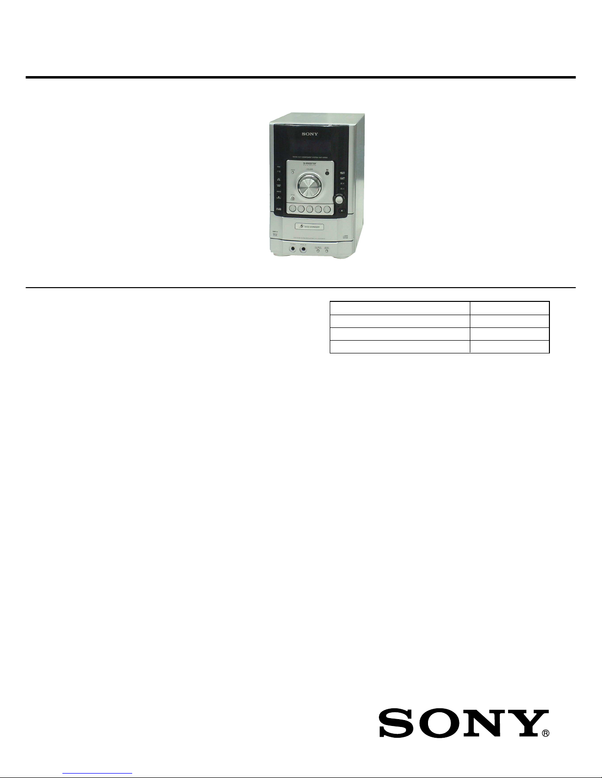
COMPACT DISC RECEIVER
HCD-HPR90/HPR99XM
SPECIFICATIONS
9-887-115-03
2007A05-1
© 2007.01
Sony Corporation
Personal Audio Division
Published by Sony Techno Create Corporation
• HCD-HPR90 is the amplifier, CD player and
tuner section in CMT-HPR90.
• HCD-HPR99XM is the amplifier, CD player
and tuner section in CMT-HPR99XM.
Photo: HCD-HPR90
US and foreign patents licensed from Dolby Laboratories.
Ver. 1.2 2007.01
US Model
Canadian Model
HCD-HPR90/HPR99XM
E Model
Australian Model
HCD-HPR90
2
HCD-HPR90/HPR99XM
Notes on chip component replacement
• Never reuse a disconnected chip component.
• Notice that the minus side of a tantalum capacitor may be
damaged by heat.
Flexible Circuit Board Repairing
• Keep the temperature of the soldering iron around 270 ˚C
during repairing.
• Do not touch the soldering iron on the same conductor of the
circuit board (within 3 times).
• Be careful not to apply force on the conductor when soldering
or unsoldering.
CAUTION
Use of controls or adjustments or performance of procedures
other than those specified herein may result in hazardous radiation
exposure.
SAFETY-RELATED COMPONENT WARNING!!
COMPONENTS IDENTIFIED BY MARK 0 OR DOTTED LINE
WITH MARK 0 ON THE SCHEMATIC DIAGRAMS AND IN
THE PARTS LIST ARE CRITICAL TO SAFE OPERATION.
REPLACE THESE COMPONENTS WITH SONY PARTS WHOSE
P ART NUMBERS APPEAR AS SHOWN IN THIS MANU AL OR
IN SUPPLEMENTS PUBLISHED BY SONY.
ATTENTION AU COMPOSANT AYANT RAPPORT
À LA SÉCURITÉ!
LES COMPOSANTS IDENTIFIÉS P AR UNE MARQ UE 0 SUR
LES DIAGRAMMES SCHÉMATIQUES ET LA LISTE DES
PIÈCES SONT CRITIQUES POUR LA SÉCURITÉ DE
FONCTIONNEMENT. NE REMPLACER CES COM- POSANTS
QUE PAR DES PIÈCES SONY DONT LES NUMÉROS SONT
DONNÉS DANS CE MANUEL OU DANS LES SUPPLÉMENTS
PUBLIÉS PAR SONY.
SAFETY CHECK-OUT
After correcting the original service problem, perform the following
safety check before releasing the set to the customer:
Check the antenna terminals, metal trim, “metallized” knobs, screws,
and all other exposed metal parts for AC leakage.
Check leakage as described below.
LEAKAGE TEST
The AC leakage from any exposed metal part to earth ground and
from all exposed metal parts to any exposed metal part having a
return to chassis, must not exceed 0.5 mA (500 microamperes.).
Leakage current can be measured by any one of three methods.
1. A commercial leakage tester, such as the Simpson 229 or RCA
WT -540A. Follow the manufactur ers’ instructions to use these
instruments.
2. A battery-operated A C milliammeter . The Data Precision 245
digital multimeter is suitable for this job.
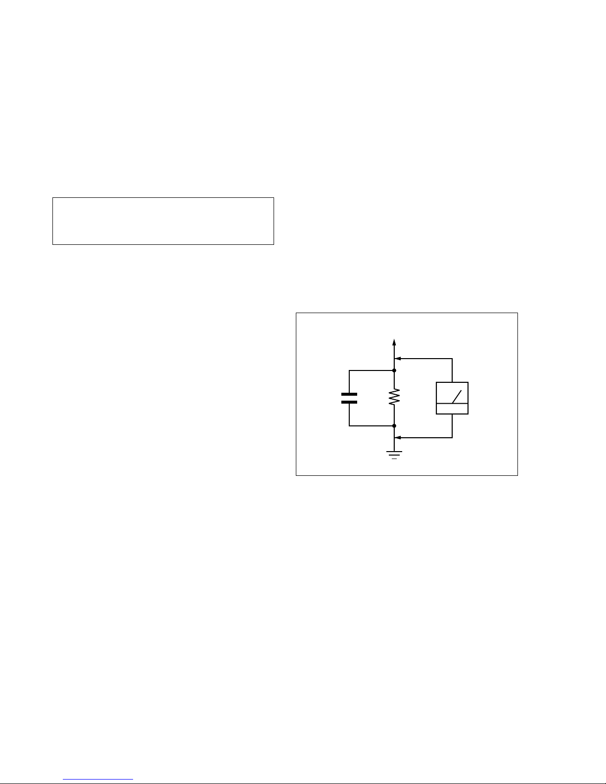
3. Measuring the voltage drop across a resistor by means of a
VOM or battery-operated AC v oltmeter. The “limit” indication
is 0.75 V, so analog meters must have an accurate low-v oltage
scale. The Simpson 250 and Sanwa SH-63Trd are examples
of a passive VOM that is suitable. Nearly all battery operated
digital multimeters that have a 2 V AC range are suitable. (See
Fig. A)
Fig. A. Using an AC voltmeter to check AC leakage.
1.5 k
Ω
0.15 µF
AC
voltmete
r
(0.75 V)
To Exposed Metal
Parts on Set
Earth Ground

3
HCD-HPR90/HPR99XM
TABLE OF CONTENTS
1. SERVICING NOTES ............................................... 4
2. GENERAL ................................................................... 5
3. DISASSEMBLY
3-1. Disassembly Flow ........................................................... 7
3-2. Case ................................................................................. 8
3-3. Back Panel ....................................................................... 8
3-4. MAIN Board.................................................................... 9
3-5. AMP Board, POWER Board Section .............................. 9
3-6. Front Panel Section, CD Mechanical (DLM5B) ............. 10
3-7. Belt (DLM3A) ................................................................. 11
3-8. Optical Pick-Up Block .................................................... 11
4. TEST MODE.............................................................. 12
5. ELECTRICAL CHECK........................................... 14
6. DIAGRAMS
6-1. Block Diagram – CD SERVO Section – ......................... 15
6-2. Block Diagram – MAIN Section – .................................. 16
6-3. Block Diagram – AMP Section – .................................... 17
6-4. Block Diagram
– PANEL, POWER SUPPLY Section – .......................... 18
6-5. Printed Wiring Board – CD Board – ............................... 20
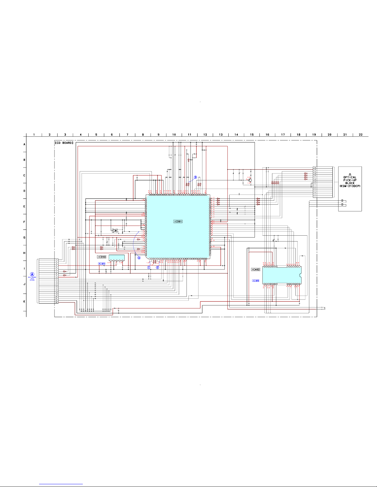
6-6. Schematic Diagram – CD Board – .................................. 21
6-7. Printed Wiring Board – MAIN Board – .......................... 22
6-8. Schematic Diagram – MAIN Section (1/3) – .................. 23
6-9. Schematic Diagram – MAIN Section (2/3) – .................. 24
6-10. Schematic Diagram – MAIN Section (3/3) – .................. 25
6-11. Printed Wiring Boards – XM Section (HPR99XM) – ..... 26
6-12. Schematic Diagram – XM Board (HPR99XM) – ........... 27
6-13. Printed Wiring Board – AMP Board – ............................ 28
6-14. Schematic Diagram – AMP Board – ............................... 29
6-15. Printed Wiring Board – PANEL Board – ........................ 30
6-16. Printed Wiring Boards – FL Section – ............................ 31
6-17. Schematic Diagram – PANEL Section – ......................... 32
6-18. Schematic Diagram – FL Board – ................................... 33
6-19. Printed Wiring Board – POWER Board – ....................... 34
6-20. Schematic Diagram – POWER Board –.......................... 35
7. EXPLODED VIEWS
7-1. Overall Section ................................................................ 52
7-2. Front Panel Section ......................................................... 53
7-3. AMP Board, POWER Board Section .............................. 54
7-4. CD Mechanical Section (DLM5B).................................. 55
8. ELECTRICAL PARTS LIST................................ 56
4
HCD-HPR90/HPR99XM
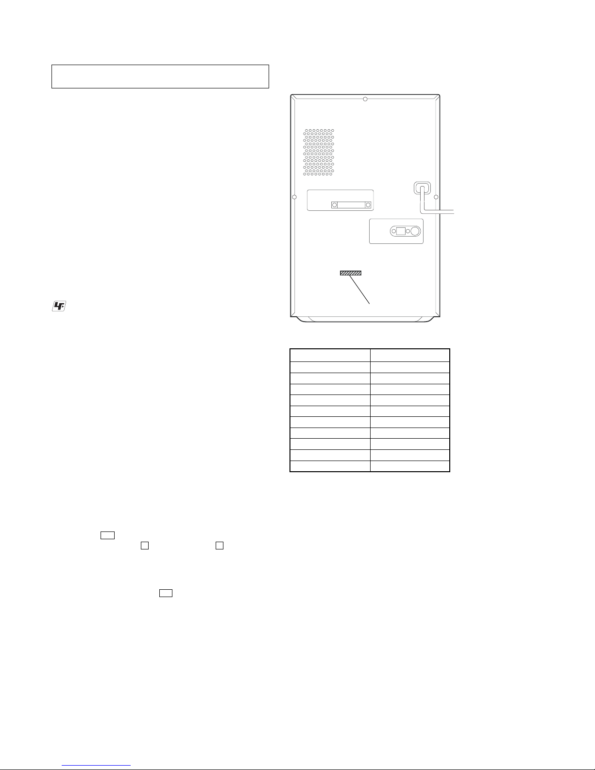
MODEL IDENTIFICATION
MODEL PART No.
HPR90: US 2-670-257-0[]
HPR90: CND 2-670-257-1[]
HPR90: E 2-670-257-2[]
HPR90: MX 2-670-257-3[]
HPR90: E51 2-670-257-4[]
HPR90: AR 2-670-257-5[]
HPR90: SP 2-670-257-6[]
HPR90: AUS 2-670-257-7[]
HPR99XM: US 2-670-258-0[]
HPR99XM: CND 2-670-258-1[]
• Abbreviation
AR : Argentina model
AUS: Australian model
CND : Canadian model
E51 : Chilean and Peruvian models
MX : Mexican model
SP : Singapore model
The laser diode in the optical pick-up block may suffer electrostatic
break-down because of the potential difference generated by the
charged electrostatic load, etc. on clothing and the human body.
During repair, pay attention to electrostatic break-down and also
use the procedure in the printed matter which is included in the
repair parts.
The flexible board is easily damaged and should be handled with
care.
NOTES ON LASER DIODE EMISSION CHECK
The laser beam on this model is concentrated so as to be focused on
the disc reflective surface by the objective lens in the optical pickup block. Therefore, when checking the laser diode emission,
observe from more than 30 cm away from the objective lens.
NOTES ON HANDLING THE OPTICAL PICK-UP
BLOCK OR BASE UNIT
SECTION 1
SERVICING NOTES
UNLEADED SOLDER
Boards requiring use of unleaded solder are printed with the leadfree mark (LF) indicating the solder contains no lead.
(Caution: Some printed circuit boards may not come printed with
the lead free mark due to their particular size)
: LEAD FREE MARK
Unleaded solder has the following characteristics.
• Unleaded solder melts at a temperature about 40 °C higher
than ordinary solder.
Ordinary soldering irons can be used but the iron tip has to be
applied to the solder joint for a slightly longer time.
Soldering irons using a temperature regulator should be set to
about 350 °C.
Caution: The printed pattern (copper foil) may peel away if
the heated tip is applied for too long, so be careful!
• Strong viscosity
Unleaded solder is more viscou-s (sticky, less prone to flow)
than ordinary solder so use caution not to let solder bridges
occur such as on IC pins, etc.
• Usable with ordinary solder
It is best to use only unleaded solder but unleaded solder may
also be added to ordinary solder.
RELEASING THE ANTITHEFT LOCK
The disc table lock function for the antitheft of an demonstration
disc in the store is equipped.
Releasing Procedure :
1. Press the I/1 button to turn the power on.
2. While pressing the x button, press the Z button until
“UNLOCKED” displayed on the fluorescent indicator tube
(around 5 seconds).
Note: When “LOCKED” is displayed, the antitheft lock is not released by
turning power on/off with the I/1 button.
PART No.
— Rear Panel —
Ver. 1.1
5
HCD-HPR90/HPR99XM
SECTION 2
GENERAL
This section is extracted from
instruction manual.
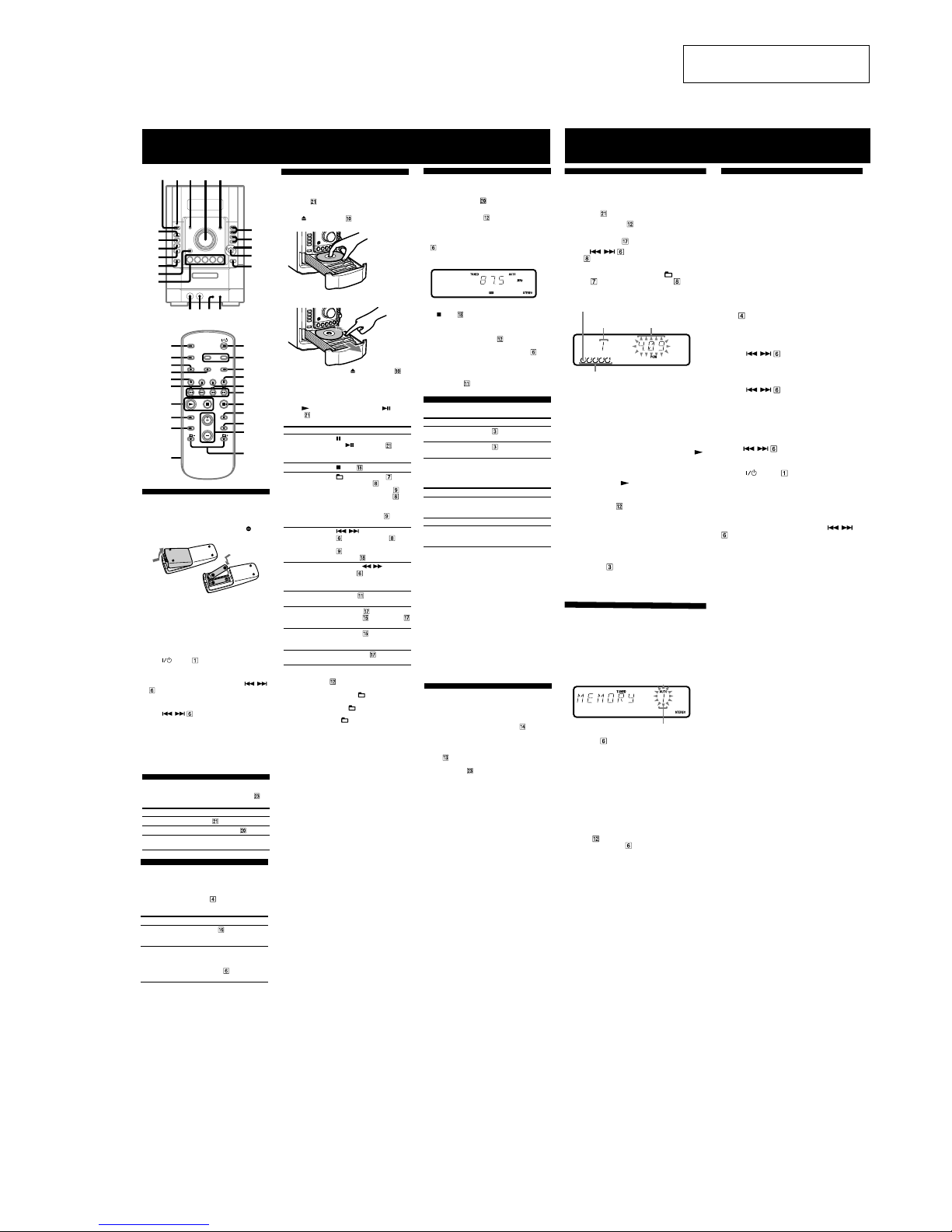
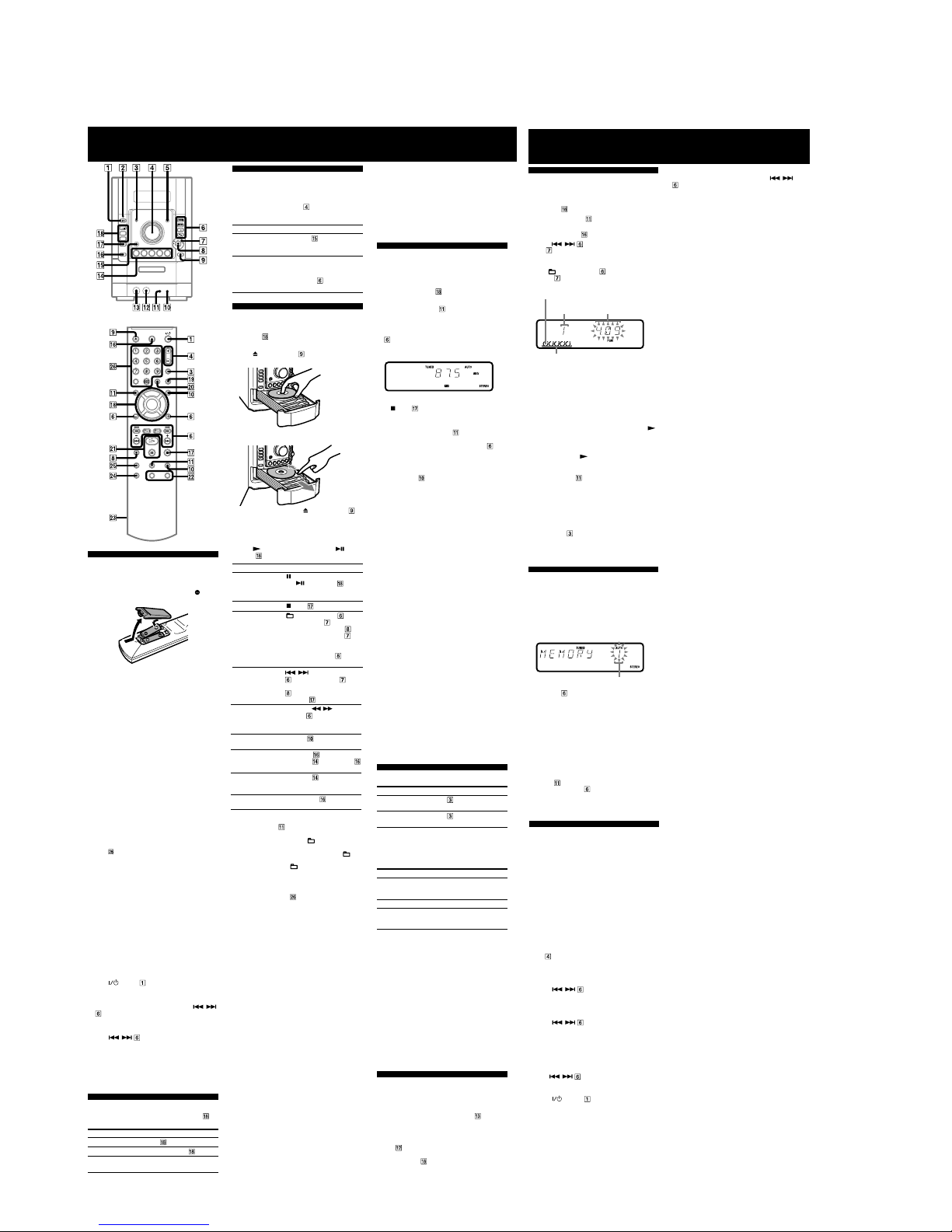
Basic Operations
Before using the system
To use the remote
Slide and remove the battery compartment lid , and
insert the two supplied R6 (size AA) batteries,
side
first, matching the polarities shown below.
Notes on using the remote
• With normal use, the batteries should last for about six months.
• Do not mix an old battery with a new one or mix different types of
batteries.
• If you do not use the remote for a long period of time, remove the
batteries to avoid damage from battery leakage and corrosion.
To set the clock
1
Turn on the system.
Press
(power) .
2
Select the clock set mode.
Press CLOCK/TIMER SET on the remote. If the
current mode appears on the display, press
/
on the remote repeatedly to select “CLOCK SET”
and then press ENTER on the remote.
3
Set the time.
Press
/ on the remote repeatedly to set
the hour, and then press ENTER on the remote.
Use the same procedure to set the minute.
When you turn off the system after setting the clock,
the clock display appears instead of the demonstration
display.
The clock settings are lost when you disconnect the
power cord or if a power failure occurs.
Selecting a music source
Press the following buttons (or press FUNCTION on
the remote repeatedly).
To select Press
CD CD on the remote.
Tuner TUNER/BAND
.
Component (connected
using an audio cord)
AUDIO IN .
Using optional audio
components
To connect an optional headphones
Connect headphones to the PHONES jack on the
unit.
To connect an optional component
Connect additional audio component to the AUDIO
IN jack
on the unit using an audio analog cord (not
supplied). Turn down the volume on the system, and then
press FUNCTION
on the remote repeatedly to select
the AUDIO IN function.
12345
wa
w;
ql
qk
qj
qh
qg
6
7
8
9
q;
qf qd qs qa
1
ws
qa
wd
w;
6
qk
9
qj
4
7
wl
3
wk
qs
ql
wa
wj
wh
wg
wf
wf
ws
9
9
ql
Other Operations
Creating your own CD program
(Program Play)
Use buttons on the remote to create your own program.
1
Press CD to select the CD function.
2
Press PLAY MODE repeatedly until “PGM”
appears while the player is stopped.
3
Press DISC SKIP to select a disc.
4
Press / repeatedly or turn the jog
dial
on the unit until the desired track number
appears.
When programming MP3 files, press
+/– (select
folder)
repeatedly or turn the jog dial on the
unit to select the desired folder, and then select the
desired file.
Current disc
Loaded disc
5
Press ENTER to add the track or file to the
program.
“– –.– –” appears when the total time exceeds 100
minutes for a CD, or when you select a CD track
whose number is 21 or over, or when you select an
MP3 file.
6
Repeat steps 4 through 5 to program additional
tracks or files, up to a total of 25 tracks or files.
7
To play your program of tracks or files, press
(play) .
The program remains available until you open the disc
tray. To play the same program again, select the CD
function, and press
(play) .
To cancel Program Play
Press PLAY MODE repeatedly until “PGM”
disappears while the player is stopped.
To delete the last track or file of the program
Press CLEAR while the player is stopped.
To view program information, such as total
track number of the program
Press DISPLAY repeatedly.
Tip
You can program additional tracks or files during playback by using
the jog dial.
Presetting radio stations
You can preset your favorite radio stations and tune
them in instantly by selecting the corresponding preset
number.
Use buttons on the remote to preset stations.
1
Tune in the desired station (see “Listening to the
radio”).
2
Press TUNER MEMORY .
Preset number
3
Press +/– repeatedly to select your desired
preset number.
If another station is already assigned to the selected
preset number, the station is replaced by the new
stations.
4
Press ENTER .
5
Repeat steps 1 through 4 to store other stations.
You can preset up to 20 FM and 10 AM stations. The
preset stations are retained for about half a day even
if you disconnect the power cord or if a power failure
occurs.
6
To call up a preset radio station, press TUNING
MODE
repeatedly until “PRESET” appears,
and then press +/–
repeatedly to select the
desired preset number.
Using the Timers
The system offers two timer functions. If you use Play
Timer with the Sleep Timer, the Sleep Timer has priority.
Sleep Timer:
You can fall asleep to music. This function works even if
the clock is not set.
Press SLEEP on the remote repeatedly. If you select
“AUTO,” the system automatically turns off after the
current disc stops or in 100 minutes.
Play Timer:
You can wake up to CD or tuner at a preset time.
Use buttons on the remote to control the Play Timer.
Make sure you have set the clock.
1
Prepare the sound source.
Prepare the sound source, and then press VOLUME
+/–
to adjust the volume.
To start from a specific CD track or MP3 file, create
your own CD program.
2
Press CLOCK/TIMER SET .
3
Press / repeatedly to select “PLAY
SET” then press ENTER .
“ON” appears, and the hour indication flashes.
4
Set the time to start playing.
Press
/ repeatedly to set the hour,
and then press ENTER .
The minute indication flashes. Use the procedure
above to set the minute.
5
Use the same procedure as in step 4 to set the
time to stop playing.
6
Select the sound source.
Press
/ repeatedly until the desired
sound source appears, and then press ENTER . The
display shows the timer settings.
7
Press (power) to turn off the system.
The system turns on 15 seconds before the preset
time.
If the system is on at the preset time, the Play Timer
will not play.
To activate or check the timer again
Press CLOCK/TIMER SELECT , press /
repeatedly until “PLAY SEL” appears, and then press
ENTER .
To cancel the timer
Repeat the same procedure as above until “TIMER OFF”
appears, and then press ENTER .
To change the setting
Start over from step 1.
Tip
The Play Timer setting remains as long as the setting is not canceled
manually.
Selected track
or file number
Total playing time of program
(including selected track or file)
9
wj
wj
wk
9
wl
ws
9
9
ws
9
Adjusting the sound
To adjust the volume
Press VOLUME +/– on the remote (or turn the
VOLUME control on the unit)
.
To add a sound effect
To Press
Generate a more dynamic
sound (Dynamic Sound
Generator X-tra)
DSGX on the unit.
Set the sound effect
EQ on the remote
repeatedly to select “BASS”
or “TREBLE,” and then
press +/–
on the remote
repeatedly to adjust the level.
wg
To Press
Pause playback
(pause) on the remote (or
CD/
(play/pause) on the
unit). To resume play, press the
button again.
Stop playback
(stop) .
Select a folder on an
MP3 disc
+/– (select folder) . Or
turn the jog dial
on the unit
and press PUSH ENTER
on
the unit (turn the jog dial
on
the unit during playback until
“GROUP” appears, and then
press PUSH ENTER
on the
unit to select the desired folder).
Select a track or file
/ (go back/go forward)
. Or turn the jog dial on
the unit and press PUSH ENTER
on the unit. To cancel, press
CANCEL
on the unit.
Find a point in a
track or file
Hold down
/ (rewind/fast
forward)
during playback,
and release the button at the
desired point.
Select Repeat Play
REPEAT
repeatedly until
“REP” or “REP1” appears.
Select a disc DISC SKIP
on the remote (or
DISC 1 – 5
or DISC SKIP
(in stop mode) on the unit).
Switch to CD
function from
another source
DISC 1 – 5
on the unit
(Automatic Source Selection).
Exchange other
discs while playing
EX-CHANGE
on the unit.
To change the play mode
Press PLAY MODE repeatedly while the player is
stopped. You can select normal play (“ALL DISCS” for
all discs, “1DISC” for a disc, or “
*” for all MP3 files
in the folder on the disc), shuffle play (“ALL DISCS
SHUF,” “1DISC SHUF,” or “
SHUF*”), or program
play (“PGM”).
* When playing a CD-DA disc, (SHUF) Play performs the same
operation as 1DISC (SHUF) Play.
Note on the jog dial
Only the first 6 characters are displayed when performing the folder
search, track search, or file search.
wj
Notes on Repeat Play
• All tracks or files on a disc are played repeatedly up to five times.
• You cannot select “REP” and “ALL DISCS SHUF” at the same
time.
• “REP 1” indicates that a single track or file is repeated until you
stop it.
Notes on playing MP3 discs
• Do not save other types of files or unnecessary folders on a disc that
has MP3 files.
• Folders that have no MP3 files are skipped.
• MP3 files are played back in the order that they are recorded onto
the disc.
• The system can only play MP3 files that have a file extension of
“.MP3.”
• If there are files on the disc that have the “.MP3” file extension,
but that are not MP3 files, the unit may produce noise or may
malfunction.
• The maximum number of:
– folders is 255 (including the root folder).
– MP3 files is 511.
–
MP3 files and folders that can be contained on a single disc is 512.
– folder levels (the tree structure of files) is 8.
• Compatibility with all MP3 encoding/writing software, recording
device, and recording media cannot be guaranteed. Incompatible
MP3 discs may produce noise or interrupted audio or may not play
at all.
Notes on playing multisession discs
• If the disc begins with a CD-DA (or MP3) session, it is recognized
as a CD-DA (or MP3) disc, and other sessions are not played back.
• A disc with a mixed CD format is recognized as a CD-DA (audio)
disc.
Changing the display
To change Press
Information on
the display*
DISPLAY repeatedly when the
system is on.
Display mode
(See below.)
DISPLAY
repeatedly when the
system is off.
* For example, you can view CD/MP3 disc information, such as the
track or file number or folder name during normal play, or the total
play time while the player is stopped.
The system offers the following display modes.
Display mode When the system is off,
1)
Demonstration The clock display is replaced by
lighting and flashing of the display
window.
Clock The clock is displayed.
Power Saving
Mode
2)
The display is turned off to conserve
power. The timer and clock continue
to operate.
1)
The STANDBY indicator lights up when the system is off.
2)
When the system is in Power Saving Mode, the following functions
are unavailable:
– setting the clock
– changing the AM tuning interval
– changing the CD power manage function
Notes on the display information
• The following are not displayed;
– total playing time for a CD-DA disc depending on the play mode.
– total playing time for an MP3 disc.
– remaining playing time for an MP3 file.
• The following are not displayed correctly;
– elapsed playing time of an MP3 file encoded using a VBR
(variable bit rate).
– folder and file names that do not follow either the ISO9660 Level
1, Level 2 or Joliet in the expansion format.
• The following are displayed;
– ID3 tag information for MP3 files when ID3 version 1 and version
2 tags are used.
– up to 62 characters of ID3 tag information using uppercase letters
(A to Z), numbers (0 to 9), and symbols (" $ % ’ ( ) * + , – . / < =
> @ [ \ ] _ ` { | } ! ? ^).
Playing a CD/MP3 disc
1
Select the CD function.
Press CD
on the remote.
2
Place a disc.
Press
(CD open/close) on the unit, and place a
disc with the label side up on the disc tray.
To insert additional discs, slide the disc tray with your
finger as shown below.
To close the disc tray, press (CD open/close) on
the unit again.
Do not force the disc tray closed with your finger, as
this may damage the unit.
3
Start playback.
Press
(play) on the remote (or CD/ (play/
pause)
on the unit).
wj
Listening to the radio
1
Select “FM” or “AM.”
Press TUNER/BAND
repeatedly.
2
Select the tuning mode.
Press TUNING MODE
repeatedly until “AUTO”
appears.
3
Tune in the desired station.
Press +/– on the remote (or TUNING +/– on the unit)
. Scanning stops automatically when a station is
tuned in, and then “TUNED” and “STEREO” (for
stereo programs) appear.
To stop automatic scanning
Press (stop) .
To tune in a station with a weak signal
If “TUNED” does not appear and the scanning does
not stop, press TUNING MODE
repeatedly until
“AUTO” and “PRESET” disappear, and then press
+/– on the remote (or TUNING +/– on the unit)
repeatedly to tune in the desired station.
To reduce static noise on a weak FM stereo
station
Press FM MODE repeatedly until “MONO” appears
to turn off stereo reception.
wh
9
9
– HPR90 –
6
HCD-HPR90/HPR99XM
Basic Operations
Before using the system
To use the remote
Slide and remove the battery compartment lid , and
insert the two supplied R6 (size AA) batteries,
side
first, matching the polarities shown below.
Notes on using the remote
• With normal use, the batteries should last for about six months.
• Do not mix an old battery with a new one or mix different types of
batteries.
• If you do not use the remote for a long period of time, remove the
batteries to avoid damage from battery leakage and corrosion.
To receive the XM Satellite Radio
Introducing XM Satellite Radio
XM Radio is the satellite radio service with millions of listeners
across the U.S. Broadcasting live daily. XM Radio offers 160
digital radio channels offering music, news, sports, comedy, talk,
entertainment, traffic and weather reports, with high quality digital
sound.
How to Subscribe
XM $12.95 monthly service subscription sold separately. XM
Connect and Play (TM) antenna required to receive XM service (sold
separately). Installation costs and other fees and taxes, including a
one-time activation fee may apply. Subscription fee is consumer only.
All fees and programming subject to change. Channels with frequent
explicit language are indicated with an XL. Channel blocking is
available for XM radio receivers by calling 1-800-XMRADIO.
Subscriptions subject to Customer Agreement available
at xmradio.com. XM service only available in the 48 contiguous
United States. XM Ready and XM Connect-and-Play are trademarks
of XM Satellite Radio Inc. (C)2005 XM Satellite Radio Inc. All rights
reserved.
Activate XM Service
Find the 8-character XM Radio ID of the Connect-and-Play antenna.
With the Connect-and-Play antenna connected to the unit, the Radio
ID can be found by selecting channel 0 on the radio. Press >10, 10/0,
10/0, 10/0
on the remote in that order to select channel 0.
Record the Radio ID here for reference: _______________________.
(NOTE: The XM Radio ID does not use the letters I, O, S, or F.)
Activate your XM Satellite Radio service online
at http://activate.xmradio.com or by calling 1-800-XMRADIO
(1-800-967-2346). You will need a major credit card.
XM will send a signal from the satellites to activate the full channel
lineup. Activation normally takes 10 to 15 minutes, but during peak
busy periods, you may need to keep your player on for up to an hour.
When you can access the full channel lineup on your player, you’re
done.
Adjusting the sound
To adjust the volume
Press VOLUME +/– on the remote (or turn the
VOLUME control on the unit)
.
To add a sound effect
To Press
Generate a more dynamic
sound (Dynamic Sound
Generator X-tra)
DSGX
on the unit.
Set the sound effect
EQ on the remote
repeatedly to select “BASS”
or “TREBLE,” and then
press +/–
on the remote
repeatedly to adjust the level.
Playing a CD/ATRAC/MP3 disc
1
Select the CD function.
Press CD
on the remote.
2
Place a disc.
Press
(CD open/close) on the unit, and place a
disc with the label side up on the disc tray.
To insert additional discs, slide the disc tray with your
finger as shown below.
To close the disc tray, press (CD open/close) on
the unit again.
Do not force the disc tray closed with your finger, as
this may damage the unit.
3
Start playback.
Press
(play) on the remote (or CD/ (play/
pause)
on the unit).
To Press
Pause playback
(pause) on the remote (or
CD/
(play/pause) on the
unit). To resume play, press the
button again.
Stop playback
(stop) .
Select a folder on
an “ATRAC” disc or
MP3 disc
+/– (select folder) . Or
turn the jog dial
on the unit
and press PUSH ENTER
on
the unit (turn the jog dial
on
the unit during playback until
“GROUP” appears, and then
press PUSH ENTER
on the
unit to select the desired folder).
Notes on playing multisession discs
• If the disc begins with a CD-DA (or “ATRAC”/MP3) session, it is
recognized as a CD-DA (or “ATRAC”/MP3) disc, and other sessions
are not played back.
• A disc with a mixed CD format is recognized as a CD-DA (audio)
disc.
Listening to the radio
To listen to FM or AM
1
Select “FM” or “AM.”
Press TUNER/BAND
repeatedly.
2
Select the tuning mode.
Press TUNING MODE
repeatedly until “AUTO”
appears.
3
Tune in the desired station.
Press +/– on the remote (or TUNING +/– on the unit)
. Scanning stops automatically when a station is
tuned in, and then “TUNED” and “STEREO” (for
stereo programs) appear.
To stop automatic scanning
Press (stop) .
Notes on XM Satellite Radio
• To ensure optimal reception of XM’s satellite signal, move your
antenna to various window locations around your home to see
where the best reception will be received. Most XM customers
place the antenna in a south-facing window with a clear view to the
sky.
• Residents in Canada please see information about XM Canada at
the following webpage: (http://www.xmradio.ca/)
To set the clock
1
Turn on the system.
Press
(power) .
2
Select the clock set mode.
Press CLOCK/TIMER SET on the remote. If the
current mode appears on the display, press
/
on the remote repeatedly to select “CLOCK SET”
and then press ENTER on the remote.
3
Set the time.
Press
/ on the remote repeatedly to set
the hour, and then press ENTER on the remote.
Use the same procedure to set the minute.
When you turn off the system after setting the clock,
the clock display appears instead of the demonstration
display.
The clock settings are lost when you disconnect the
power cord or if a power failure occurs.
wd
8
ws
8
ql
wa
wa
Select a track or file
/ (go back/go forward)
. Or turn the jog dial on
the unit and press PUSH ENTER
on the unit. To cancel, press
CANCEL
on the unit.
Find a point in a
track or file
Hold down
/ (rewind/fast
forward)
during playback,
and release the button at the
desired point.
Select Repeat Play
REPEAT
repeatedly until
“REP” or “REP1” appears.
Select a disc DISC SKIP
on the remote (or
DISC 1 – 5
or DISC SKIP
(in stop mode) on the unit).
Switch to CD
function from
another source
DISC 1 – 5
on the unit
(Automatic Source Selection).
Exchange other
discs while playing
EX-CHANGE
on the unit.
To change the play mode
Press PLAY MODE repeatedly while the player is
stopped. You can select normal play (“ALL DISCS” for
all discs, “1DISC” for a disc, or “
*” for all “ATRAC”
files and MP3 files in the folder on the disc), shuffle
play (“ALL DISCS SHUF,” “1DISC SHUF,” or “
SHUF*”), or program play (“PGM”).
* When playing a CD-DA disc, (SHUF) Play performs the same
operation as 1DISC (SHUF) Play.
To select a CD track using the number
buttons
Press the number buttons on the remote during
normal play. For example, to enter 20, press >10, 2, 10/0,
in that order.
To create an “ATRAC”/MP3 disc
You can create an “ATRAC” disc and MP3 disc with the
SonicStage software. SonicStage can be
downloaded free of charge from the following sites and
installed on your computer.
For customers in the U.S.A.:
<http://www.sony.com/shelfsupport>
For customers in Canada:
<http://www.sony.ca/ElectronicsSupport/>
Please see the instructions at the sites or SonicStage Help
of the software for how to install and how to create an
“ATRAC”/MP3 disc.
Note on the jog dial
Only the first 6 characters are displayed when performing the folder
search, track search, or file search.
Notes on Repeat Play
• All tracks or files on a disc are played repeatedly up to five times.
• You cannot select “REP” and “ALL DISCS SHUF” at the same
time.
• “REP 1” indicates that a single track or file is repeated until you
stop it.
To tune in a station with a weak signal
If “TUNED” does not appear and the scanning does
not stop, press TUNING MODE
repeatedly until
“AUTO” and “PRESET” disappear, and then press
+/– on the remote (or TUNING +/– on the unit)
repeatedly to tune in the desired station.
To reduce static noise on a weak FM stereo
station
Press FM MODE repeatedly until “MONO” appears
to turn off stereo reception.
To listen to XM
You can operate and listen to the XM satellite Radio by
connecting your XM Connect-and-Play antenna. Before
using the system, connect the XM Connect-and-Play
antenna to the XM jack of the system (see “Hooking up
the system securely”).
1
Select “XM.”
Press XM on the remote (or TUNER/BAND
repeatedly) .
2
Select the All Channel mode.
Press TUNING MODE repeatedly until “CAT”
and “PRESET” disappear.
3
Tune in the desired channel.
Press +/– on the remote (or TUNING+/– on the unit)
repeatedly.
To select a channel by Category mode
1
Press XM on the remote (or TUNER/BAND
repeatedly) .
2
Press TUNING MODE repeatedly until “CAT”
appears.
3
Press CATEGORY +/– on the remote (or CAT
+/– on the unit) repeatedly.
4
Press +/– on the remote (or TUNING +/– on the
unit) repeatedly.
To select a channel using the number
buttons
Press the number buttons on the remote. For example,
to enter 20, press >10, 10/0, 2, 10/0, in that order. You
cannot enter 255 or more.
Notes
• If you select a channel that is not broadcasted, “OFF AIR” appears
and the previous channel is selected.
• If you select a channel using the number buttons in Category mode,
the tuning mode changes to All Channel mode automatically.
Changing the display
To change Press
Information on
the display*
DISPLAY repeatedly when the
system is on.
Display mode
(See below.)
DISPLAY
repeatedly when the
system is off.
* For example, you can view CD/“ATRAC”/MP3 disc information,
such as the track or file number or folder name during normal play,
or the total play time while the player is stopped. You can also view
XM radio information, such as the channel name, song title and
artist name.
The system offers the following display modes.
Display mode When the system is off,
1)
Demonstration The clock display is replaced by
lighting and flashing of the display
window.
Clock The clock is displayed.
Power Saving
Mode
2)
The display is turned off to conserve
power. The timer and clock continue
to operate.
1)
The STANDBY indicator lights up when the system is off.
2)
When the system is in Power Saving Mode, the following functions
are unavailable:
– setting the clock
– changing the AM tuning interval
– changing the CD power manage function
Notes on the display information
• The following are not displayed;
– total playing time for a CD-DA disc depending on the play mode.
– total playing time for an “ATRAC”/MP3 disc.
– remaining playing time for an MP3 file.
• The following are not displayed correctly;
– elapsed playing time of an “ATRAC” file or MP3 file encoded
using a VBR (variable bit rate).
– folder and file names that do not follow either the ISO9660 Level
1, Level 2 or Joliet in the expansion format.
• The following are displayed;
– ID3 tag information for “ATRAC” files and MP3 files when ID3
version 1 and version 2 tags are used.
– up to 62 characters of ID3 tag information using uppercase letters
(A to Z), numbers (0 to 9), and symbols (" $ % ’ ( ) * + , – . / < =
> @ [ \ ] _ ` { | } ! ? ^).
Using optional audio
components
To connect an optional headphones
Connect headphones to the PHONES jack on the
unit.
To connect an optional component
Connect additional audio component to the AUDIO
IN jack
on the unit using an audio analog cord (not
supplied). Turn down the volume on the system, and then
press FUNCTION
on the remote repeatedly to select
the AUDIO IN function.
Selecting a music source
Press the following buttons (or press FUNCTION on
the remote repeatedly).
To select Press
CD CD on the remote.
Tuner TUNER/BAND
.
Component (connected
using an audio cord)
AUDIO IN .
qk
Notes on playing MP3 discs
• Do not save other types of files or unnecessary folders on a disc that
has “ATRAC” and MP3 files.
• Folders that have no “ATRAC” and MP3 files are skipped.
• “ATRAC” and MP3 files are played back in the order that they are
recorded onto the disc.
• The system can only play MP3 files that have a file extension of
“.MP3.”
• If there are files on the disc that have the “.MP3” file extension,
but that are not MP3 files, the unit may produce noise or may
malfunction.
• The maximum number of:
– “ATRAC” folders is 255.
– “ATRAC” files is 999.
– MP3 folders is 255 (including the root folder).
– MP3 files is 511.
–
MP3 files and folders that can be contained on a single disc is 512.
– folder levels (the tree structure of files) is 8.
Other Operations
Creating your own CD program
(Program Play)
Use buttons on the remote to create your own program.
1
Press CD to select the CD function.
2
Press PLAY MODE repeatedly until “PGM”
appears while the player is stopped.
3
Press DISC SKIP to select a disc.
4
Press / repeatedly or turn the jog
dial
on the unit until the desired track number
appears.
When programming “ATRAC” files or MP3 files,
press
+/– (select folder) repeatedly or turn the
jog dial
on the unit to select the desired folder, and
then select the desired file.
Current disc
Loaded disc
5
Press ENTER to add the track or file to the
program.
“– –.– –” appears when the total time exceeds 100
minutes for a CD, or when you select a CD track
whose number is 21 or over, or when you select an
“ATRAC” file or MP3 file.
6
Repeat steps 4 through 5 to program additional
tracks or files, up to a total of 25 tracks or files.
7
To play your program of tracks or files, press
(play) .
The program remains available until you open the disc
tray. To play the same program again, select the CD
function, and press
(play) .
To cancel Program Play
Press PLAY MODE repeatedly until “PGM”
disappears while the player is stopped.
To delete the last track or file of the program
Press CLEAR while the player is stopped.
To view program information, such as total
track number of the program
Press DISPLAY repeatedly.
Tip
You can program additional tracks or files during playback by using
the jog dial.
Presetting radio stations
You can preset your favorite radio stations and tune
them in instantly by selecting the corresponding preset
number.
Use buttons on the remote to preset stations.
1
Tune in the desired station (see “Listening to the
radio”).
2
Press TUNER MEMORY .
Preset number
3
Press +/– repeatedly to select your desired
preset number.
If another station is already assigned to the selected
preset number, the station is replaced by the new
stations.
4
Press ENTER .
5
Repeat steps 1 through 4 to store other stations.
You can preset up to 20 FM, 10 AM and 20 XM
stations. The preset stations are retained for about half
a day even if you disconnect the power cord or if a
power failure occurs.
6
To call up a preset radio station, press TUNING
MODE
repeatedly until “PRESET” appears,
and then press +/–
repeatedly to select the
desired preset number.
Note on presetting XM stations
You cannot preset XM stations except when you receive the station.
To activate or check the timer again
Press CLOCK/TIMER SELECT , press /
repeatedly until “PLAY SEL” appears, and then press
ENTER .
To cancel the timer
Repeat the same procedure as above until “TIMER OFF”
appears, and then press ENTER .
To change the setting
Start over from step 1.
Tip
The Play Timer setting remains as long as the setting is not canceled
manually.
Selected track
or file number
Total playing time of program
(including selected track or file)
Using the Timers
The system offers two timer functions. If you use Play
Timer with the Sleep Timer, the Sleep Timer has priority.
Sleep Timer:
You can fall asleep to music. This function works even if
the clock is not set.
Press SLEEP on the remote repeatedly. If you select
“AUTO,” the system automatically turns off after the
current disc stops or in 100 minutes.
Play Timer:
You can wake up to CD or tuner at a preset time.
Use buttons on the remote to control the Play Timer.
Make sure you have set the clock.
1
Prepare the sound source.
Prepare the sound source, and then press VOLUME
+/–
to adjust the volume.
To start from a specific CD track, “ATRAC” file or
MP3 file, create your own CD program.
2
Press CLOCK/TIMER SET .
3
Press / repeatedly to select “PLAY
SET” then press ENTER .
“ON” appears, and the hour indication flashes.
4
Set the time to start playing.
Press
/ repeatedly to set the hour,
and then press ENTER .
The minute indication flashes. Use the procedure
above to set the minute.
5
Use the same procedure as in step 4 to set the
time to stop playing.
6
Select the sound source.
Press
/ repeatedly until the desired
sound source appears, and then press ENTER . The
display shows the timer settings.
7
Press (power) to turn off the system.
The system turns on 15 seconds before the preset
time. If the system is on at the preset time, the Play
Timer will not play.
8
wa
wa
w;
wg
8
wf
ws
8
8
8
ws
8
8
• If “ATRAC” files and MP3 files are recorded on the same disc, this
system plays the “ATRAC” files first.
• Compatibility with all MP3 encoding/writing software, recording
device, and recording media cannot be guaranteed. Incompatible
MP3 discs may produce noise or interrupted audio or may not play
at all.
qk
qa
6
qk
qa
6
6
wh
– HPR99XM –
HCD-HPR90/HPR99XM
7
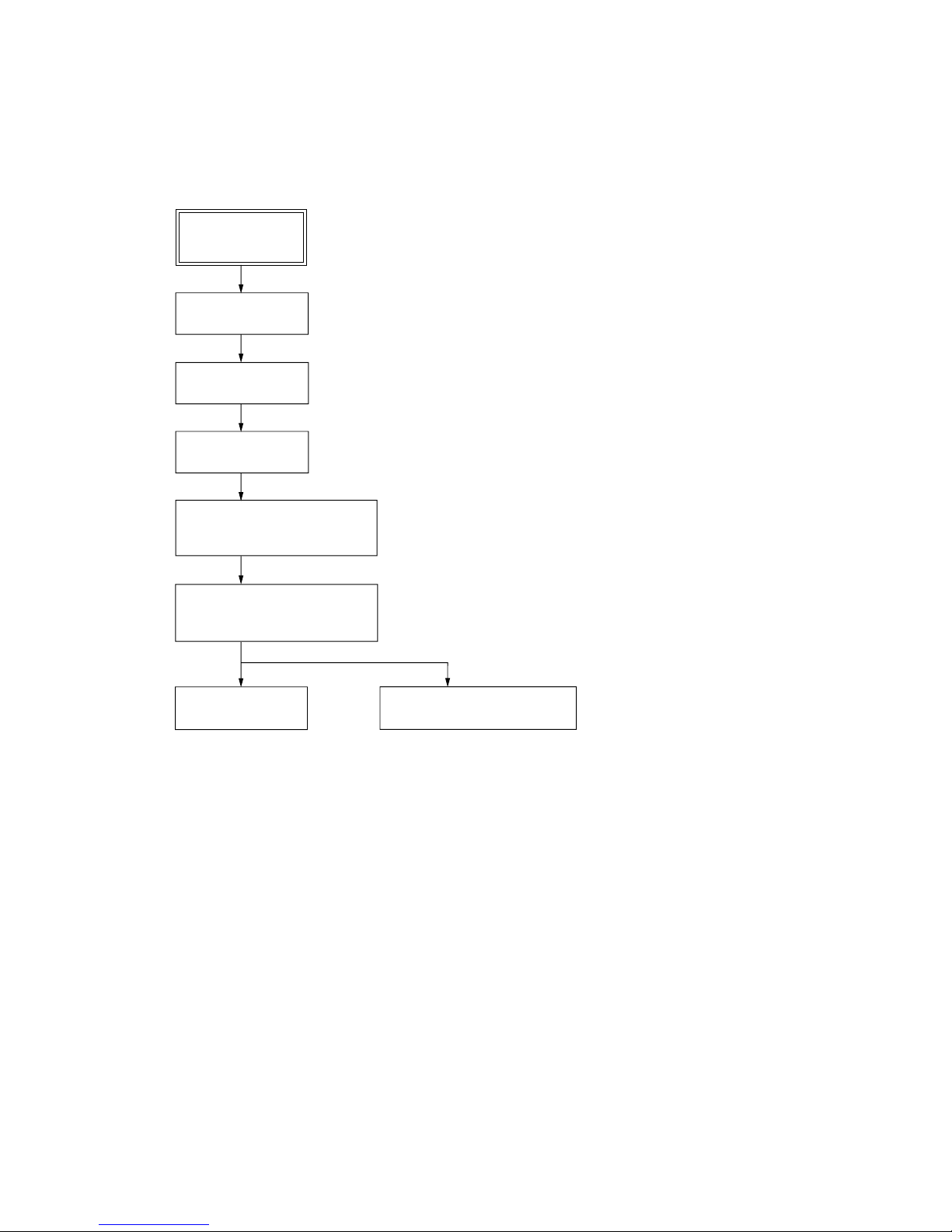
• This set can be disassembled in the order shown below.
3-1. DISASSEMBLY FLOW
SECTION 3
DISASSEMBLY
SET
3-2. CASE
(Page 8)
3-3. BACK PANEL
(Page 8)
3-4. MAIN BOARD
(Page 9)
3-6. FRONT PANEL SECTION,
CD MECHANICAL (DLM5B)
(Page 10)
3-7. BELT (DLM3A)
(Page 11)
3-8. OPTICAL PICK-UP BLOCK
(Page 11)
3-5. AMP BOARD,
POWER BOARD SECTION
(Page 9)
HCD-HPR90/HPR99XM
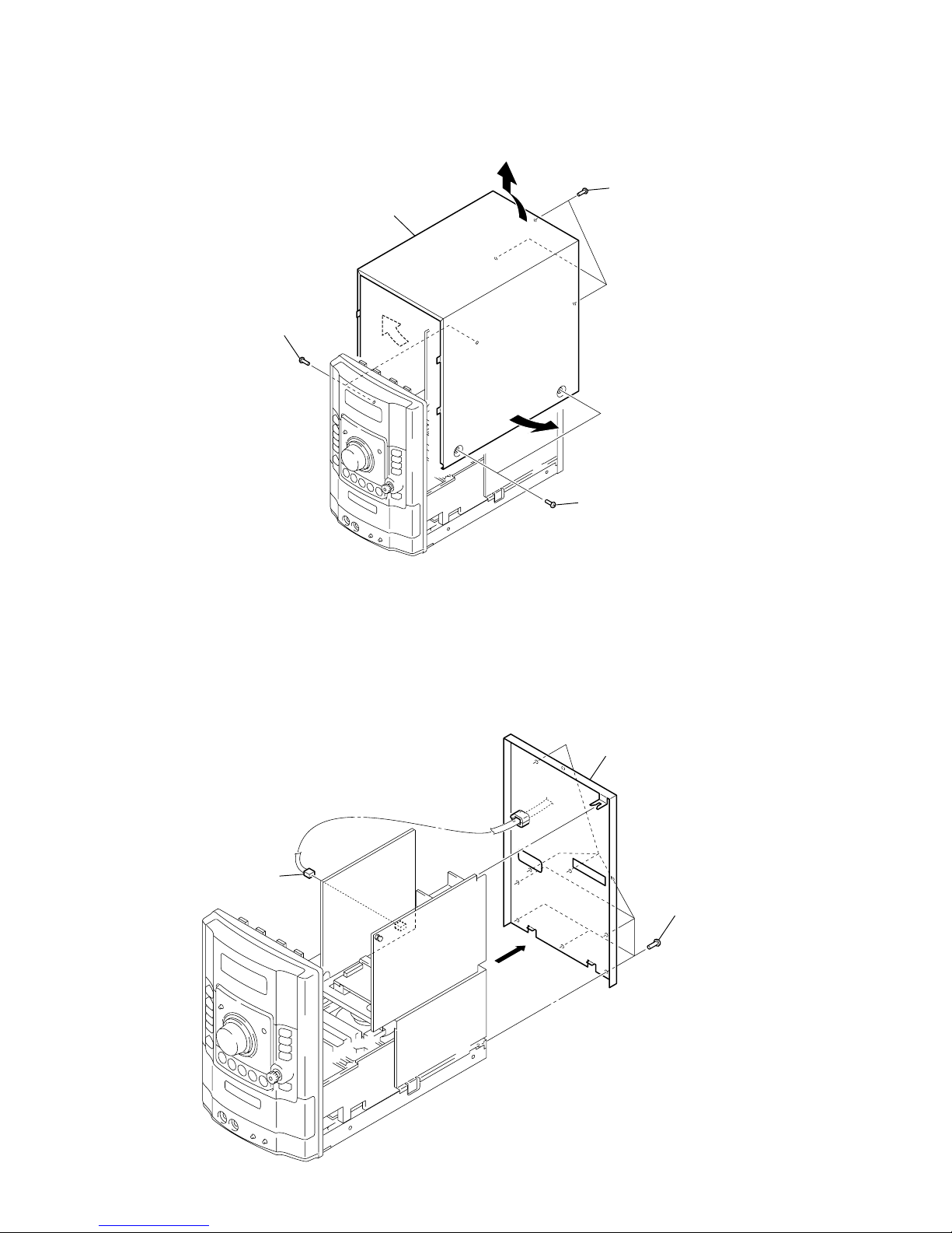
8
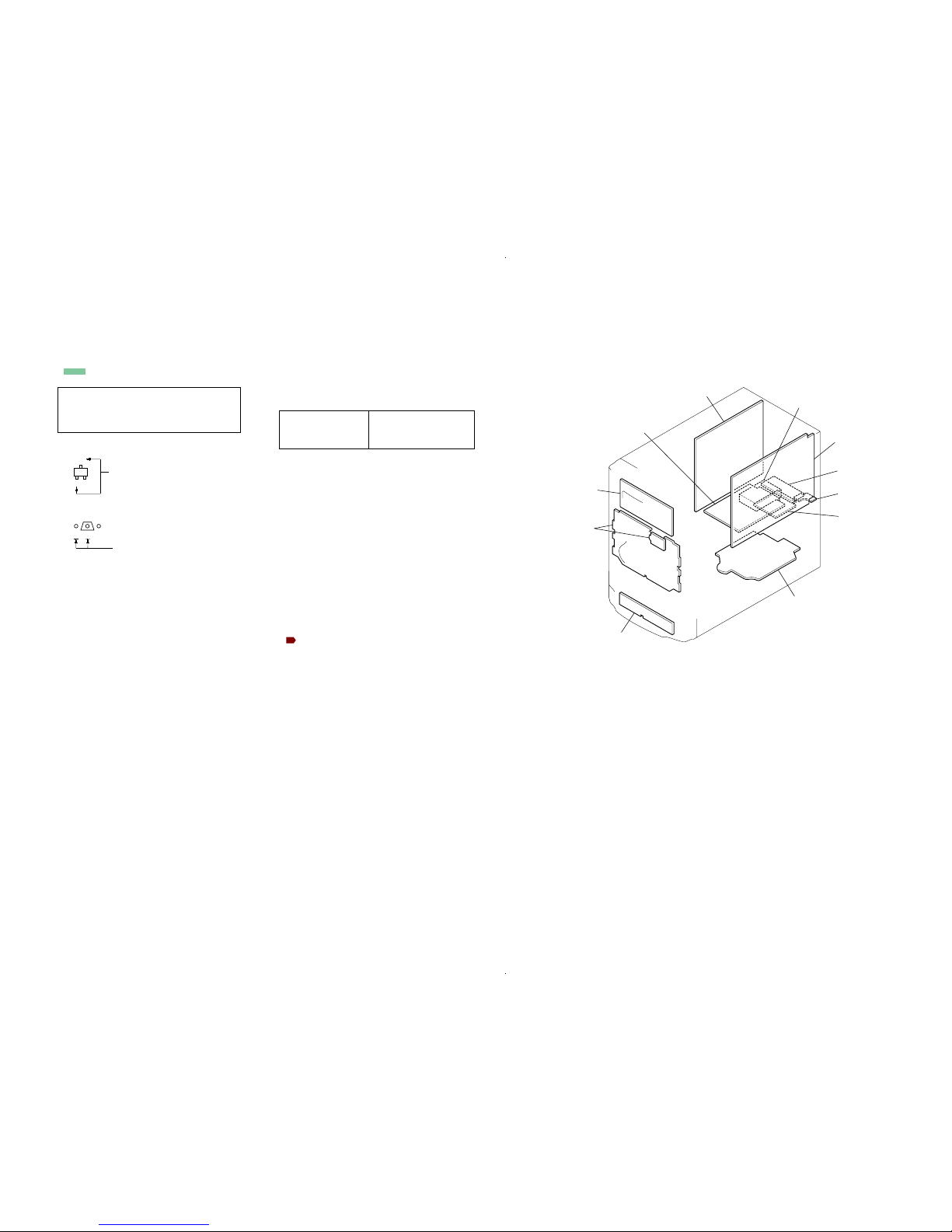
3-3. BACK PANEL
Note: Follow the disassembly procedure in the numerical order given.
3-2. CASE
2
three screw
s
(B3)
5
case
1
two screws
(case 3 TP2)
4
3
3
1
two screws
(case 3 TP2)
2
eight screws
(B3)
3
back panel
1
power cord connector
(CN1)
HCD-HPR90/HPR99XM
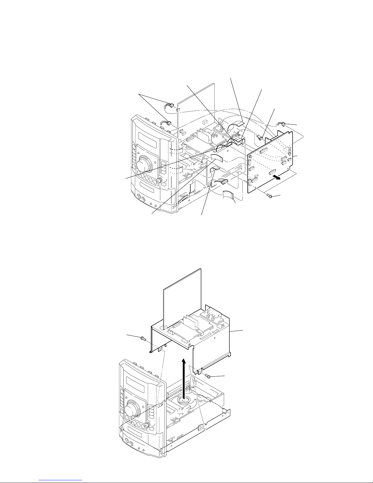
9
3-4. MAIN BOARD
3-5. AMP BOARD, POWER BOARD SECTION
6
two screws (B3)
qa
MAIN boar
d
7
5
two connectors
(CN32, CN604)
5
connector
(CN1203)
3
flexible flat (15 core) cable
(CN1308)
4
flexible flat (19 core) cable
(CN1302)
1
flexible flat (9 core) cable
(CN1306)
9
flexible flat (9 core) cable
(CN1310)
2
flexible flat (11 core) cable
(CN1305)
q;
flexible flat (15 core) cable
(HPR99XM model)
(CN1301)
8
flexible flat (23 core) cable
(CN1309)
5
connector
(HPR99XM model)
(CN1205)
1
screw
(B3)
1
screw
(B3)
2
3
AMP board,
POWER board section
HCD-HPR90/HPR99XM
10
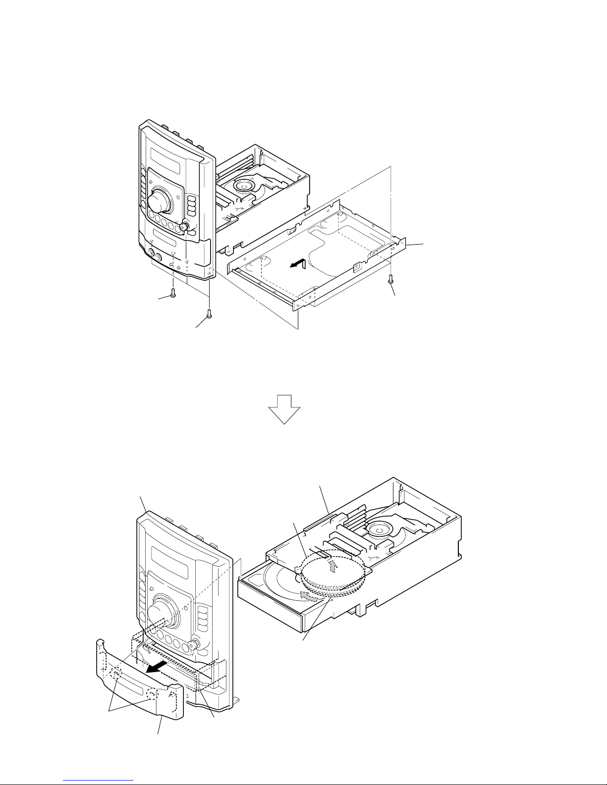
3-6. FRONT PANEL SECTION, CD MECHANICAL (DLM5B)
3
four screws
(BVTP3 × 8)
2
screw
(BVTT3 × 6)
4
5
chassi
s
1
three screws
(B3)
A
B
6
Turn the lower gear in the direction of the arrow A,
untill the upper gear gose up to the high position.
7
Draw out the tray fully in the
direction of the arrow B.
8
two claws
9
lid (CD)
upper gear
q;
front panel section
qa
CD mechanical
(DLM5B)
HCD-HPR90/HPR99XM
11
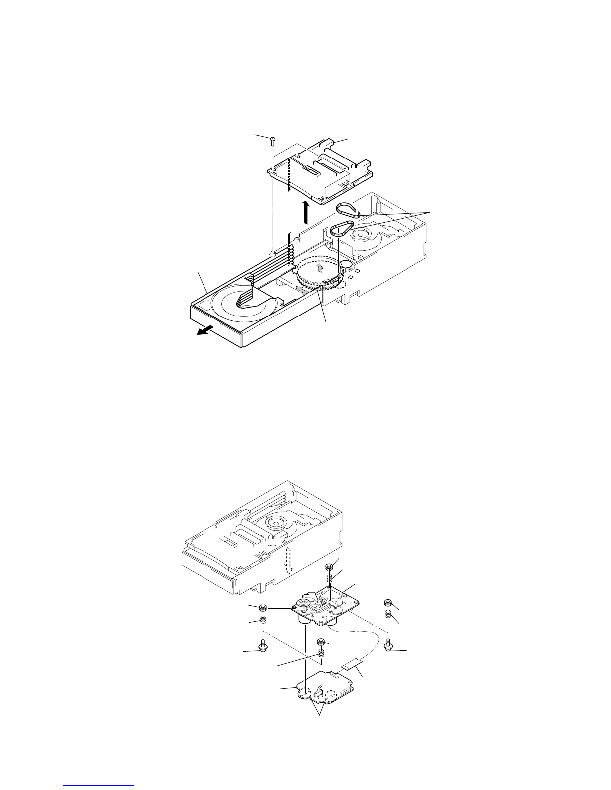
3-7. BELT (DLM3A)
3-8. OPTICAL PICK-UP BLOCK
3
four screws
4
plate cam
5
two belts
(DLM3A)
A
B
1
Turn the lower gear in the direction of the arrow A,
untill the upper gear gose up to the high position.
2
Draw out the tray fully in the
direction of the arrow B.
1
flexible flat (16 core) cable
(CN301)
2
two screws
(PTPWH M2.6)
6
Remove four solders.
2
two screws
(PTPWH M2.6)
3
coil spring (insulator
)
3
coil spring (insulator)
3
coil spring (insulator)
4
3
coil spring (insulator)
5
insulator
5
insulator
7
CD board
8
optical pick-up block
5
insulator
5
insulator

12
HCD-HPR90/HPR99XM
CD SHIP MODE
This mode moves the optical pick-up to the position durable to
vibration. Use this mode when returning the set to the customer
after repair.
Procedure:
1. Press the I/1 button to turn the power on.
2. Press the [CD] or [FUNCTION] key on the remote commander
to select “CD”.
3. Press two buttons of x and [DISC 1] simultaneously.
4. After the “STANDBY” display blinks, “LOCK” is displayed
on the fluorescent indicator tube, and the ship mode is set.
CD SHIP MODE & MEMORY CLEAR
This mode is used to perform CD ship mode and cold reset
simultaneously.
Procedure:
1. Press the I/1 button to turn the power on.
2. Press the [CD] or [FUNCTION] key on the remote commander
to select “CD”.
3. Press three buttons of [DSGX], Z and [DISC 1] simultaneously.
4. After the “STANDBY” display blinks, “LOCK” is displayed
on the fluorescent indicator tube, and the ship mode is set.
ANTITHEFT LOCK MODE
This mode is used to unable to take sample disc out of disc table in
the shop.
Procedure:
1. Press the I/1 button to turn the power on.
2. Insert the CD.
3. Press the CD u button.
4. Press two buttons of x and Z for 5 seconds.
5. The message “LOCKED” is displayed on the fluorescent
indicator tube and the disc slot is locked. (Even if pressing
the
Z button, the message “LOCKED” is displayed on the
fluorescent indicator tube and the disc table is locked)
6. To release from this mode, press two buttons of x and Z for
5 seconds.
7. The message “UNLOCKED” is displayed on the fluorescent
indicator tube and the disc table is unlocked.
CD POWER MANAGE
This mode is used to changed over CD power on/of f for decreasing
of reception noise in the tuner mode.
Procedure:
1. Press the I/1 button to turn the power on.
2. Press the [CD] or [FUNCTION] key on the remote commander
to select “CD”.
3. Press the I/1 button again to turn the power off.
4. Press two buttons of [PUSH ENTER] and I/1 simultaneously.
5. The message “CD POWER” is displayed on the fluorescent
indicator tube momentarily, then display changes “ON” or
“OFF”, and CD power on/off changed ov er in the tuner mode.
COLD RESET
The cold reset clears all data including preset data stored in the
RAM to initial conditions. Execute this mode when returning the
set to the customer.
Procedure:
1. Press three buttons of [PLAY MODE/TUNING MODE], [DISPLAY]
and I/1 simultaneously.
2. The fluorescent indicator tube becomes blank momentarily,
then becomes standby states.
COMMON TEST MODE
This mode is used to check operations of Amplifier.
Procedure:
1. Press the I/1 button to turn the power on.
2. Press three buttons of [DSGX], [PLAY MODE/TUNING MODE]
and [DISPLAY] simultaneously.
3. When the COMMON test mode is activated, “SLEEP” and
“c PLAY” blink on the fluorescent indicator tube.
4. Each time [EQ] button on the remote commander is pressed,
the display changes starting “TONE MIN”, “TONE FLAT”
and “TONE MAX” this order.
5. Turn the [VOLUME] knob counterclockwise, “VOL MIN” is
displayed on the fluorescent indicator tube. Turn the [VOLUME]
knob clockwise, “VOL MAX” is displayed on the fluorescent
indicator tube.
6. To release this mode, press the I/1 button.
PANEL TEST MODE
This mode is used to check the fluorescent indicator tube, LED,
model, destination, software version and key.
Procedure:
1. Press the I/1 button to turn the power on.
2. Press three buttons of [PLAY MODE/TUNING MODE], [AUDIO IN]
and [DISPLAY] simultaneously.
3. Fluorescent indicator tube is all turned on and each LED of
[DSGX] and [STANDBY] blink every 0.5 seconds.
4. When you want to enter the model, destination and version display
mode, press the [DISPLAY] button. The model and destination
are displayed alternately on the fluorescent indicator tube.
5. Press the [DISPLAY] button again MC version display on the
fluorescent indicator tube.
6. When [AUDIO IN] button is pressed while the MC version is
displayed, year, month and day of the software creation display .
When [AUDIO IN] button is pressed again, the display returns
to the MC version display.
7. Press the [PUSH ENTER] button, the key check mode is
activated.
8. In the key check mode, the fluorescent indicator tube displays
“K 0 J0 V0”.
9. Each time a button is pressed, “K” value increases. Howe ver,
once a button is pressed, it is no longer taken into account.
All keys are pressed, display becomes “K21”.
10. “V” value increases 1, 2, 3 ... if turn the [VOLUME] knob
clockwise, or it decreases 0, 9, 8 ... if turn the knob
counterclockwise
“J” value increases like 1, 2, 3 ... if turn the jog knob clockwise,
or it decreases like 0, 9, 8 ... if turn the knob counterclockwise.
11. To release this mode, press three keys in the same manner as
step 2, or disconnect the power cord.
SECTION 4
TEST MODE

13
HCD-HPR90/HPR99XM
CD SERVICE MODE
This mode can run the CD sled motor freely. Use this mode, for
instance, when cleaning the optical pick-up.
Procedure:
1. Press the I/1 button to turn the power on.
2. Press the [CD] or [FUNCTION] key on the remote commander
to select “CD”.
3. Press three buttons of [PUSH ENTER], [DSGX] and [DISC 1]
simultaneously, the message “SERVICE IN” is displayed on
the fluorescent indicator tube.
4. Press the M L button to move the optical pick-up to outside
track and the message “SLED OUT” is displayed on the
fluorescent indicator tube, or press the l m button to
inside track and the message “SLED IN” is displayed on the
fluorescent indicator tube.
5. Press the x button, “LD OFF” is displayed and laser diode is
turned off. Each time x button is pressed, laser diode ON/
OFF switch is performed.
6. To release this mode, press the I/1 button.
TUNER STEP CHANGE-OVER
A step of AM tuning interval can be changed over between 9 kHz
or 10 kHz.
Procedure:
1. Press the I/1 button to turn the power on.
2. Press the [TUNER/BAND] button to select “AM”.
3. Press the I/1 button again to turn the power off.
4. Press two buttons of M L and I/1 simultaneously.
5. The message “STEP 9kHz” or “STEP 10kHz” is displayed on
the fluorescent indicator tube and thus the tuning interval is
changed over.
14
HCD-HPR90/HPR99XM
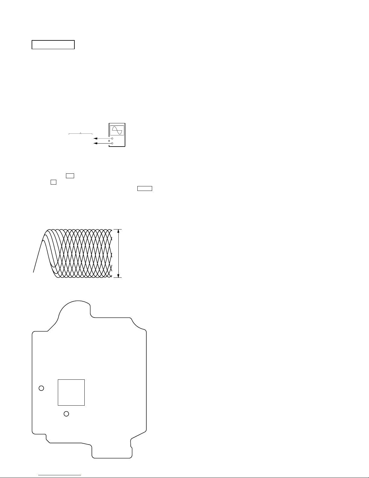
Checking Location:
+
–
CD board
TP (RFACI)
TP (VC)
oscilloscop
e
(DC range)
Procedure :
1. Connect oscilloscope to TP (RFACI) and TP (VC) on the CD
board.
2. Press the I/1 button to turn the power on, and press
the Z button to open the CD disc table.
3. Set disc (YEDS-18) on the tray and press the CD u button
to playback.
4. Confirm that oscilloscope waveform is as shown in the figur e
below. (eye pattern)
A good eye pattern means that the diamond shape (◊) in the
center of the waveform can be clearly distinguished.
VOLT/DIV: 200 m
V
TIME/DIV: 500 ns
level:
0.9
±
0.4 Vp-p
TP
(VC)
TP
(RFACI)
IC201
– CD Board (Conductor Side) –
CD SECTION
Note:
1. CD Block is basically constructed to operate without adjustment.
2. Use YEDS-18 disc (3-702-101-01) unless otherwise indicated.
3. Use an oscilloscope with more than 10 MΩ impedance.
4. Clean the object lens by an applicator with neutral detergent when the
signal level is low than specified value with the following checks.
5. Check the focus bias check when optical pick-up block is replaced.
FOCUS BIAS CHECK
SECTION 5
ELECTRICAL CHECK
HCD-HPR90/HPR99XM
1515
HCD-HPR90/HPR99XM
SECTION 6
DIAGRAMS
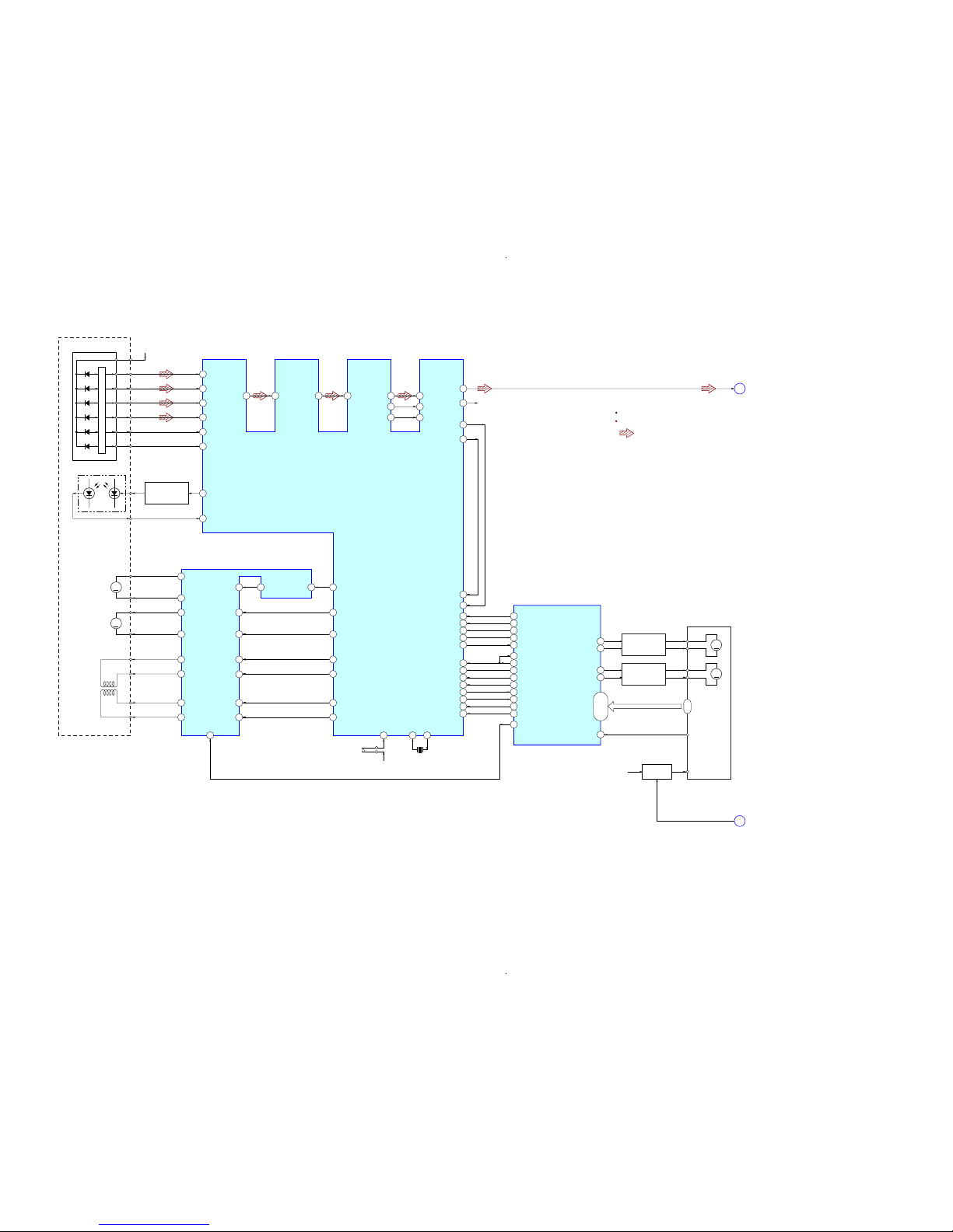
6-1. BLOCK DIAGRAM – CD SERVO Section –
(Page 16)
CD DSP
IC201
CH2RIN
MUTE
2-AXIS
DEVICE
(TRACKING)(FOCUS)
57
64
A
3.3V
(CD)
DETECTOR
A
AC_
SUM
58 B
65
EG_
IN
70RFACO 71 RFACI 3PCMD
112
AOUT1
117AOUT2
4 PCMDI
5BCK
55FEO
53TEO
52TEI
54FEI
6 BCKI
R-CH
1LRCK 2 LRCKI
59 C
60 D
50 E
51 F
66 LD
67 PD
16 CH4OUTF
15 CH4OUTR
27 OPOUT 38 MDP
AUTOMATIC
POWER CONTROL
Q321
LD
PD
LASER DIODE
OPTICAL PICK-UP
BLOCK
(KSM-213DCP)
B
C
D
E
F
41 SFDR
42 SRDR
43 TFDR
44 TRDR
45 FFDR
46 FRDR
DATA
I-V AMP
M401
(SPINDLE)
M402
(SLED)
17 CH3OUTF
18 CH3OUTR
14 CH1OUTF
13 CH1OUTR
12 CH2OUTF
11 7
20
89
SSTP
39
CH2FIN
6
CH1RIN
5
CH1FIN
4
CH3RIN
22
CH3FIN
23
CH4IN
24
OPIN+
2
CH2OUTR
M
M
FOCUS/TRACKING COIL DRIVE,
SPINDLE/SLED MOTOR DRIVE
IC402
S201
(LIMIT)
3.3V
(CD)
108
XTAO
109
XTAI
X201
16.9344MHz
CLOK
11
XLAT
16
SENS
20
SCOR
26
DATA2
12
CLK2
90
XLAT-MP3
13
REQ-MP3
14
IREQ-MP3
10
ACK-MP3
15
XTACN
7
XRST
8
35
CD DATA
37
CD CLK
43
CD XLT
19
CD SCOR
6
MP3 DATA IN
5
MP3 DATA OUT
7
MP3 CLK
46
MP3 XLAT
45
MP3 REQ
47
MP3 IREQ
44
MP3 ACK
49
CD XTACN
48
CD XRST
50
CD DRIVER MUTE
36
CD SENS
LOADING MOTOR
DRIVE
Q1610 – 1613
M1+
41
M1–
42
M
CAM GEAR MOTOR
DRIVE
Q1614 – 1617
M2+
39
M2–
DLM5B E0,
E1/SW2,
E2/SW1,
E3/SW3,
SW5 – SW8
E0, E1/SW2,
E2/SW1,
E3/SW3,
SW5 – SW8
40
A
CD-L
STANDBY LED
SYSTEM CONTROLLER
IC1301 (1/4)
: CD PLAY
SIGNAL PATH
R-ch is omitted due to same as L-ch.
27, 34, 33,
28, 26 – 23
M1+
M1+
M
M2+
M2+
DLM5B DISC SENS
22
COLLECTOR
ANODE
CD MECHANISM
DECK BLOCK
B+ SWITCH
Q1618
CDM +3.3V
D
(Page 18)
HCD-HPR90/HPR99XM
1616
HCD-HPR90/HPR99XM
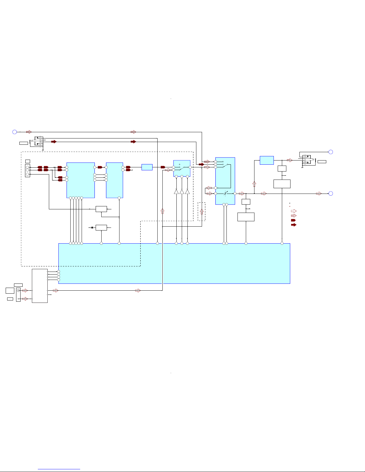
AUDIO IN
R-CH
J981
CD-L
A
TUNER (FM/AM)
AM
FM ANT
AM ANT
L-OUT
R-OUT
DO/STEREO
R-CH
ST DIN
ST CLK
ST CE
FM 75Ω
COAXIAL
ANTENNA
56 ST DIN/STEREO
9
4
5
7
10A9
B
54 ST DOUT
55 ST CLK
53 ST CE
SEL A51SEL B
59
14SI13
SC
AMP SI
61
AMP SC
63
LINE MUTE
60
HP MUTE
58
AUDIO IN DETECT
100
C
L-CH
B
HP
X
OUT1
INPUT SELECTOR, ELECTRICAL VOLUME,
SURROUND/TONE CONTROL
IC1501
SYSTEM CONTROLLER
IC1301 (2/4)
: TUNER (FM/AM)
: CD PLAY
SIGNAL PATH
R-ch is omitted due to same as L-ch.
: XM
: AUDIO IN
PHONES
R-CH
J982
15
14
6
INH
SEL INH
65
5
SC_RX_IN3SC_TX_OUT
XM TXD
31
XM RXD
32
7
CDM_SEL
9
ERR_IRQ#
XM DTIC CMD
85
RDS INT/XM DTIC IRQ
18
11
RST#
RDS DATA/XM DTIC RST
21
XM POWER 5V
83
XM POWER 3.3V
82
Q1503
Q1504
Q1505
TUNER/XM
SELECT SWITCH
IC1505
13
X1
X2
C1
SEL1
VIN1
B1
19
18
COMM_RX_N
COMM_RX_P
A1
1
MUTING
IC1503
R-CH
17
MUTING
CONTROL SWITCH
Q1501, 1502
MUTING
IC1504
R-CH
MUTING
CONTROL SWITCH
Q1508, 1509
HEADPHONE
AMP
IC1502
LINE AMP
IC051
XM RECEIVER
IC001
D/A CONVERTER
IC041
J001
XM
3
2
1
D+
D–
VCC
22
23
COMM_TX_N
COMM_TX_P
5
PDN
2
3
BICK
SDTI
1
4
MCLK
LRCK
39
37
I2S_CLK
I2S_DA
11
AOUTL
10
AOUTR R-CH
43
41
I2S_OCLK
I2S_LRCLK
B+ SWITCH
Q1601, 1602
XM
+3.3V
+4V
B+ SWITCH
Q001, 003
XM
+5.2V
(HPR99XM)
(HPR90)
D1205
6-2. BLOCK DIAGRAM – MAIN Section –
(Page 15)
(Page 18)
(Page 17)

HCD-HPR90/HPR99XM
1717
HCD-HPR90/HPR99XM
6-3. BLOCK DIAGRAM – AMP Section –
(Page 16)
SYSTEM CONTROLLER
IC1301 (3/4)
L-CH
C
1
A/D CONVERTER
IC701
STREAM PROCESSOR
IC705
LIN
31
DATA
15
SCKI
DOUT
12
30
BCK
BCK
11
29
LRCK
36
XFSIIN
48
XFSOIN
LRCK
12
S-MASTER DATA
70
OUTL1
11
OUTL2
9
OUTR1
6
OUTR2
4
X702
49.152MHz
21
SCDT
S-MASTER SHIFT
71
22
SCSHIFT
S-MASTER LATCH
72
23
SCLATCH
S-MASTER PG MUTE
66
20
PGMUTE
S-MASTER SOFT MUTE
67
19
SOFTMUTE
S-MASTER NSP MUTE
73
18
NSPMUTE
S-MASTER INIT
75
27
INIT
S-MASTER RST
68
S-MASTER SD
69
CLOCK SHIFT
IC703
CLOCK BUFFER
IC709
DIGITAL POWER AMP
IC707
2
BP
17
AP
3
/SD
OUT_B
29
OVER LOAD
DETECT
Q702, 703
OVER LOAD
DETECT
Q752, 753
OUT_A
25
OUT_B
30
OUT_A
26
4
/RST
DIGITAL POWER AMP
IC708
2DP
17 CP
3
/SD
OUT_D
29
OUT_C
25
OUT_D
30
OUT_C
26
4
/RST
L.P.F.
L.P.F.
L.P.F.
L.P.F.
PROTECT
DETECT
Q701
R
L
+
–
+
–
SPEAKER
J860
: TUNER (FM/AM)
SIGNAL PATH
R-ch is omitted due to same as L-ch.
HCD-HPR90/HPR99XM
1818
HCD-HPR90/HPR99XM
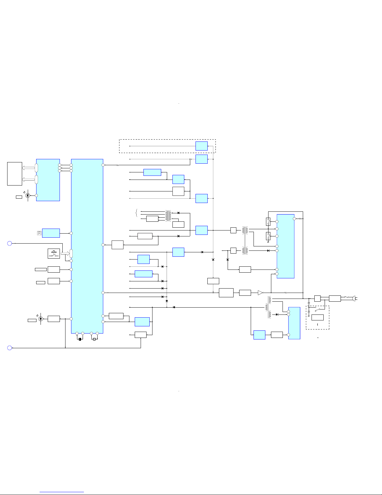
REMOTE CONTROL
RECEIVER
IC951
FL901
FLUORESCENT
INDICATOR
TUBE
1 LED1
FLUORESCENT INDICATOR
TUBE DRIVER
IC901
SYSTEM CONTROLLER
IC1301 (4/4)
57POWER ON/OFF
20AC CUT
RESET SIGNAL
GENERATOR
IC1302
RESET SWITCH
Q1301
B+ SWITCH
Q952
38CDM SD
84AC DET
12RESET
94 VOLUME
SEG1 – SEG16
31 – 42 14 – 29
GR1 – GR12
KEY1 – KEY3
93 – 91
D952
DSGX
88 STANDBY LED
4 SIRCS
D951
STANDBY
LED DRIVE
Q951
ROTARY
ENCODER
VOLUME
PUSH ENTER
RV952
95 JOG
ROTARY
ENCODER
RV951
(JOG)
13
XOUT15XIN
X1302
5MHz
11
XCOUT10XCIN
X1301
32.768kHz
DIN
FL SD7 1
CLK
FL SCK8 2
STB
FL STB9 3
74 WAKE UP KEY
S951 – 957,
S961 – 966,
S971 – 975
(AC IN)
T603
SUB POWER
TRANSFORMER
T31
MAIN POWER
TRANSFORMER
F1
LINE FILTER
T1
RECT
D1
+
+
S1
VOLTAGE
SELECTOR
120 – 127V
220 – 240V
(HPR90: E, E51)
(HPR99XM)
D603
D14
4
POWER CONTROL
IC601
VCC
5
DRAIN
2
FB
POWER CONTROL
IC11
1
VENSE
2
F/B
9
OCP
16
VG (H)
ISOLATOR
PH601
ISOLATOR
PH11
ISOLATOR
PH602
SHUNT
REGULATOR
IC650
D1206
D1208 – 1210,1213
D1212
18
VD
SWITCHING
Q12
12
VG (L)
SWITCHING
Q11
15
VS
8
VC1
Q601
RECT
D32
RECT
D31
D1211
D652 D33
+28V
+4V
+3.3V
(CD)
+1.8V
(CD)
MOTOR
B+
D1204
+3.3V
(AMP)
+1.8V
(AMP)
D1203 (1/2)
D1201
+3.3V
(FL)
D1203 (2/2)
CDM
+3.3V
+3.3V
(LED)
EVER
+3.3V
+7V
+9V
+7V
REGULATOR
IC1205
+9V
REGULATOR
IC1202
+12V
REGULATOR
IC1201
+4V
REGULATOR
IC1203
REGULATOR
Q1607 – 1609
PROTECT
DETECT
Q1606
+5V
+5V
REGULATOR
IC1206
+12V
XM +5.2V
+5V
REGULATOR
IC1204
+9V
(HP AMP)
+3.3V
(ADC )
RIPPLE
FILTER
Q1510
+3.3V REGULATOR
IC702
+1.8V REGULATOR
IC704
+1.8V
REGULATOR
IC203
D1202
DC DETECT
Q651, 652
POWER ON/OFF
RELAY DRIVE
Q650
VEE
FLUORESCENT
INDICATOR TUBE
(FL901)
RECT
D912, 922
OSC
Q921, 922
F1
F2
T921
INVERTER
TRANSFORMER
HP
B
STANDBY LED
D
Abbrivation
: Chilean and Peruvian modelsE51
6-4. BLOCK DIAGRAM – PANEL, POWER SUPPLY Section –
(Page
16)
(Page
15)
HCD-HPR90/HPR99XM
1919
HCD-HPR90/HPR99XM
• Circuit Boards Location• Note For Printed Wiring Boards and Schematic Diagrams
• Indication of transistor
Note on Schematic Diagram:
• All capacitors are in µF unless otherwise noted. (p: pF)
50 WV or less are not indicated except for electrolytics
and tantalums.
• All resistors are in Ω and 1/
4
W or less unless otherwise
specified.
• f : internal component.
• 2 : nonflammable resistor.
• C : panel designation.
• A : B+ Line.
• B : B– Line.
• Voltages and waveforms are dc with respect to ground
under no-signal (detuned) conditions.
– CD Board –
no mark :CD PLAY
– XM Board –
no mark : XM
– Other Boards –
no mark : TUNER (FM/AM)
(): CD PLAY
〈〈 〉〉 : XM
∗ : Impossible to measure
• Voltages are taken with a V OM (Input impedance 10 MΩ).
Voltage variations may be noted due to normal production tolerances.
• Waveforms are taken with a oscilloscope.
Voltage variations may be noted due to normal production tolerances.
• Circled numbers refer to waveforms.
• Signal path.
F : TUNER (FM/AM)
J : CD PLAY
: XM
f : AUDIO IN
• Abbreviation
AR : Argentina model
AUS: Australian model
CND : Canadian model
E51 : Chilean and Peruvian models
MX : Mexican model
SP : Singapore model
Note on Printed Wiring Board:
• X : parts extracted from the component side.
• Y : parts extracted from the conductor side.
• f : internal component.
• : Pattern from the side which enables seeing.
(The other layers' patterns are not indicated.)
Caution:
Pattern face side: Parts on the pattern face side seen from
(Conductor Side) the pattern face are indicated.
Parts face side: Parts on the parts face side seen from
(Component Side) the parts face are indicated.
• Circuit Boards Location
C
B
These are omitted.
E
Q
B
These are omitted.
CE
Q
The components identified by
mark 0 or dotted line with
mark 0 are critical for safety.
Replace only with part number
specified.
Les composants identifiés par une
marque 0 sont critiques pour la
sécurité.
Ne les remplacer que par une pièce
portant le numéro spécifié.
XM REG boar
d
(HPR99XM)
XM board
(HPR99XM)
MAIN board
CD board
TUNER
SP board
POWER board
AMP board
FL board
HP A-IN board
PANEL board
Ver. 1.1
HCD-HPR90/HPR99XM
2020
HCD-HPR90/HPR99XM
R256
C257
R260
C206
C205
C322
R323
R322
R321
R324
C223
C321
C268
C267
R271
R203
C226
R201
C227
C110
C108
C102
C203
C204
C101
C274
C202
R207
C215
R202
C201
R423
R421
C424
C276
C210
Q321
C207
C266
C275
C323
C277
C406
R401
C401
C219
R276
C271
C272
C104
C105
C107
C109
C232
C220
X201
IC203
C403
R257
C258
C260
C261
R258
C304
C208
R101
R265
R266
R267
C264
C265
R278
C111
C214
R270
C221
C292
C291
R292
R291
IC201
C217
C218
C224
R451
R102
R103
R104
R105
R107
R108
R109
R110
R111
C451
IC402
C256
C251
C252
C254
C253
R254
R255
R252
R253
CN301
C213
C222
C405
R113
C404
R452
C112
R275
R277
C103
R112
C301
C303
C273
R268
C113
CN102
C230
R250
R280
M401
M402
S201
E
1-868-067-
12
(12)
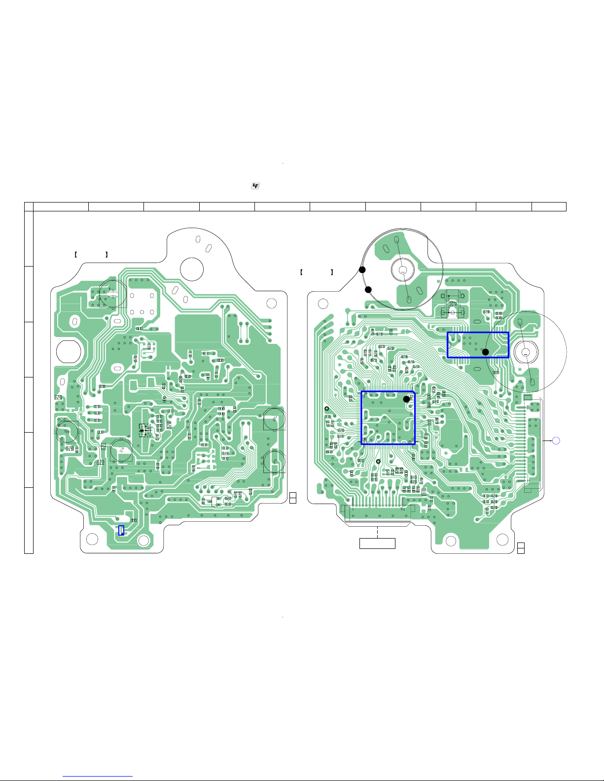
CD BOARD
(COMPONENT SIDE)
135
4
1-868-067-
12
(12)
CD BOARD
(CONDUCTOR SIDE)
M
M
1
17 14
28 22821 15
30
90
91
120
60
31
61
(SPINDLE)
(LIMIT)
(SLED)
A
MAIN
BOARD
CN1309
TP
(RFACI)
TP
(VC)
OPTICAL PICK-UP BLOCK
(KSM-213DCP)
A
B
C
D
E
F
1 2 3 4 567 8 9 10
6-5. PRINTED WIRING BOARD – CD Board –
: Uses unleaded solder.
(Page 22)
• See page 19 for Circuit Boards Location.
HCD-HPR90/HPR99XM
2121
HCD-HPR90/HPR99XM
C208
C205
R324
R101
R292
C110
R451
R102
R103
R104
R105
R107
R108
R109
R110
R111
R255
R253
C406
R254
R252
R250
R268
R322
R321
C264
CN301
C222
C213
R291
C201
C219
R112
R113
C203
C108
C102
C101
C103
C105
C111
C104
C109
C107
C113
C112
R275
R277
R276 C271
C221
C273
C261
C260
R265
R266
R267
R258
C258
R260
C256
C207
C254
C253
C252
C251
C232
C206
C224
R278
C272
C204
C218
C291
C292
C217
C202
R401
C303
C321
R323
R421
C404
R207 C226
C265
C210
R256
C257
C323
C424
R423
C405
M402
M401
IC402
TP
C230
TP
C220
C274
R257
C304
IC201
C401
R202
C268 C215
C276
C277
R201
CN102
C266C267
R203
C275
C214
X201
R270
R271
C223
R280
R452 C451
Q321
S201
C227
IC203
C301
C322
0.1
0.1
100k
100
100
220p
22k
100
100
100
100
100
100
100
100
100
1k
1k
0.1
10k
10k
1M
10k
2.2
2.2
1000p
16P
0.1
0.1
100
100
10V
0.1
100
100
100
10V
220p
22p
22p
22p
22p
220p
220p
220p
220p
22p
22p
100
100
47k 0.1
0.1
470p
0.01
0.47
4.7k
1k
4.7k
220k
220p
0
0.1
100 10V
4700p
470p
4700p
470p
0.1
0.1
0.1
100
0.1
0.1
0.1
470p
470p
0.1
0.1
0
10
1000p
0
0
0.1
01
0.1
0.1
22k
0.1
100
10V
0.1
10k
0.1
BA5947FM
100p
0.1
0.1
100k
1
CXD3014A-201R
220
10V
0
10p 0.1
1
1
0
23P
10p5p
5p
0.1
16.9344MHz
1k
1M
0.1
0
10k 0.047
2SA2119K
1
BH18LB1WG-TR
0.1
1
SP-
SP
+
SP+
SP-
SL+
SL-
S
L+
SL-
OPIN-
OPIN+
CH1FIN
CH1RIN
CH2FIN
CH2RIN
GND
CNF4
POWVCC
CH2OUTR
CH2OUTF
CH1OUTR
CH1PUTF
CH4OUTR
CH4OUTF
CH3OUTF
CH3OUTR
POWVCC
MUTE
GND
CH3RIN
CH3FIN
CH4IN
CH4CAPA
OPOUT
PREVCC
VREF
GAIN-SW
MIRR
DFCT
FOK
VSS
LOCK
MDP
SSTP
IOVSS1
SFDR
SRDR
TFDR
TRDR
FFDR
FRDR
IOVDD1
AVDD0
AVSS0
E
F
TEI
TEO
FEI
FEO
VC
A
B
C
D
AVDD4
RFDCO
PDSENS
AC_SUM
EG_IN
LD
PD
RFC
AVSS4
RFACO
RFACI
AVDD3
BIAS
ASYI
ASYO
VPCO
VCTL
AVSS3
CLTV
FILO
FILI
PCO
BCKI
LRCKI
LRCK
VSS
PCMD
BCK
VDD
IOVDD2
DOUT
TEST
IOVSS2
XVSS
XTAO
XTAI
XVDD
AVDD1
AOUT1
VREFL
AVSS1
AVSS2
VREFR
AOUT2
AVDD2
IOVDD0
IOVSS0
XTACN
XRST
VSS
VDD
SENS
WFCK
XUGF
XPCK
GFS
C2PO
SCOR
VDD
COUT
PCMDI
CLOK
SVSS
SVDD
SVSS
SVDD
VSS
SVDD
VDD
VSS
TEST1
SVSS
SVSS
SVDD
JTAGTCK
JTAGTDI
JTAGTDO
JTAGTMS
TRST
VDD
TES1
PLLVDD
PLLVSS
ACK-MP3
REQ-MP3
IREQ-MP3
SSTB-MP3
XLAT-MP3
XLAT
CLK2
DATA
DATA2
T+
VC
GND
LD
PD
F+
T-
F-
VCC
D-OUT
E
D
A
B
C
F
VR
GND
(LIMIT)
AUTOMATIC
POWER
CONTROL
CD DSP
FOCUS/TRUCKING
(SPINDLE)
(SLED)
(VC)
(RFACI)
+1.8V REGULATOR
D-GND
L-CH
A-GND
R-CH
M-GND
M+7V
COIL DRIVE,
SPINDLE/SLED
MOTOR DRIVE
D-MUTE
XATCN
NC
VOUT
VIN
STBY
CD DATA
MP3 CLK
D+3.3V
A+3.3V
CD XRST
MP3 IREQ
CD CLK
MP3 DATA
MP3 XLAT
MP3 REQ
MP3 ACK
CD XLAT
CD SENS
CD SCOR
6-6. SCHEMATIC DIAGRAM – CD Board –
• See page 36 for Waveforms. • See page 37 for IC Block Diagrams. • See page 44 for IC Pin Function Description.
(Page
25)

HCD-HPR90/HPR99XM
2222
HCD-HPR90/HPR99XM
R1383
R1385
R1318
R1321
C1515
R1331
R1332
R1674
JR1007
JR1008
JR1009
JR1010
JR1011
JR1012
JR1013
Q1601
D1205
JR1002
R1512
R1523
R1573
R1516
R1514
R1513
Q1505
C1506
Q1503
Q1504
JR1014
JR1003
R1511
R1606
R1605
Q1602
JR1001
JR1004
JR1005
JR1006
IC1505
JR1501
JR1502
JR1503
C1615
R1420
R1642
C1612
R1643
R1693
R1692
R1347
R1348
R1525
R1346
R1345
R1343
R1510
IC1504
R1560
R1575
R1507
R1557
Q1509
Q1508
R1504
R1433
R1434
R1334
R1333
R1336
R1335
R1370
R1337
D1204
R1344
IC1502
R1349
R1350
Q1510
R1550
R1558
R1559
C1531
R1505
R1515
R1503
R1553
R1565
R1555
R1554
R1627
R1631
R1639
R1635
R1626
R1630
R1638
R1634
R1629
R1628
R1632
R1633
R1640
R1641
R1636
R1637
Q1610
Q1612
Q1616
Q1614
Q1611
Q1613
Q1617
Q1615
Q1609
Q1608
Q1606
R1625
R1622
R1623
R1621
R1620
R1619
R1615
R1616
C1603
R1422
Q1618
R1644
C1628
C1211
IC1204
C1213
R1556
C1501
R1506
R1363
R1361
R1518
R1520
R1502
Q1501
Q1502
R1519
R1521
C1503
R1648
R1646
R1501
R1552
C1208
C1206
C1204
R1456
R1551
C1218
R1427
D1305
R1428
R1352
R1353
R1354
R1355
R1356
R1372
R1373
R1375
R1369
R1371
R1368
R1367
R1366
R1474
R1425
R1424
R1328
R1327
R1326
R1325
R1324
R1323
R1320
R1319
R1322
R1421
R1418
R1429
R1430
C1401
C1402
R1423
R1402
R1401
C1403
C1312
C1404
Q1301
R1412
R1417
R1316
C1310
C1311
C1316
R1426
D1203
D1202
IC1301
D1303
R1397
R1395
R1394
R1393
R1392
R1391
R1388
R1497
R1493
R1492
R1491
R1487
R1486
R1500
R1400
R1313
R1311
R1309
R1307
R1306
R1305
R1304
R1303
R1302
R1301
R1604
C1362
R1603
IC1302
D1201
C1202
R1203
R1202
R1201
C1636
C1665
JR1614
JR1618
C1217
R1645
R1357
C1524
JW1087
CN1301
JW1024
JW1029
JW1132
JW1103
JW1057
JW1035
JW1067
JW1251
JW1036
JW1051
JW1088
JW1613
JW1612
JW1002
JW1065
JW1076
C1526
C1576
JW1049
JW1072
JW1007
JW1013
JW1044
JW1041
JW1032
JW1014
JW1033
JW1017
JW1008
JW1011
JW1015
JW1038
JW1016
JW1070
JW1068
JW1003
JW1023
JW1006
JW1058
JW1055
JW1030
JW1102
JW1107
JW1025
JW1026
JW1027
JW1034
JW1040
JW1046
JW1047
JW1052
JW1053
JW1063
JW1064
JW1071
JW1073
JW1074
JW1075
JW1077
JW1078
JW1079
JW1080
JW1081
JW1083
JW1084
JW1085
JW1086
JW1092
JW1093
JW1095
JW1100
JW1101
JW1104
JW1105
JW1106
JW1108
JW1109
JW1110
JW1111
JW1112
JW1113
JW1114
JW1115
JW1116
JW1120
JW1121
JW1122
JW1129
JW1130
JW1133
JW1134
JW1135
C1507
JW1022
JW1021
JW1018
JW1012
JW1010
JW1031
JW1050
JW1056
JW1039
JW1096
JW1099
JW1138
JW1037
JW1005
JW1091
JW1082
JW1089
JW1139
JW1140
JW1043
JW1028
JW1062
JW1061
JW1009
JW1045
JW1141
JW1042
JW1097
JW1098
JW1069
JW1066
JW1060
JW1059
JW1004
JW1001
JW1127
JW1128
JW1615
C1664
C1629
C1616
C1613
D1212
C1518
C1519
C1520
C1521
C1522
C1614
C1558
C1552
C1508
C1565
C1567
C1532
C1635
C1517
CN1309
IC1201
Q1607
EP1201
D1213
CN1307
C1207
C1561
D1211
C1513
C1563
C1209
C1511
CN1310
C1212
C1205
C1562
C1512
C1559
C1509
C1504
C1555
C1505
C1523
C1214
CN1203
IC1202
IC1205
IC1203
C1502
CN1305
D1210
D1209
C1301
C1201
X1302
D1208
CN1302
CN1306
EP1202
CN1308
X1301
C1203
CN1205
JW1094
D1206
D1207
JW1131
JW1020
JW1123
JW1124
JW1126
JW1137
JW1136
C1550
JW1048
JW1118
JW1117
JW1119
JW1090
CN1201
CN1202
IC1501
IC1503
EEEE
EEEE
E
E
E
E
19
E
E
E
E
1
2
1
1
2
3
1
3
131313
E
E
E
E
E
13
E
E
E
1
2
22
23
(CHASSIS)
(CHASSIS)
(CHASSIS)
K
A
1
100
81 80
51
50
3130
1-869-726-
11
(11)
MAIN BOARD
1
3
4
5
J
HP A-IN BOARD
CN981
A
CD BOARD
CN102
3
1
5
4
K
K
A
K
K
A
K
K
A
K
K
A
(HPR99XM)
(HPR90: US, CND, E, E51,
MX, AR/HPR99XM)
H
AMP BOARD
CN700
(HPR99XM)
(HPR90)
(HPR90)
D
FL
BOARD
C
PANEL
BOARD
F
POWER
BOARD
CN32
E
AMP
BOARD
CN705
P
XM
BOARD
CN001
Q
XM REG
BOARD
CN1204
G
POWER
BOARD
CN604
(HPR99XM)
(HPR90)
(HPR90)
TUNER(FM/AM)
SUPPLIED WITH THE
ASSEMBLED BLOCK
FM 75Ω
COAXIAL
ANTENNA
AM
8
9
2
1
CD MECHANISM
DECK BLOCK
SUPPLIED WITH
THE ASSEMBLED
BLOCK
(HPR99XM)
K
K
A
4
6
1
1
3
4
6
3
A
B
C
D
E
F
G
H
I
J
1 2 3 4 5 6 7 8 9 10 11 12 13
• Semiconductor
Location
Ref. No. Location
D1201 B-3
D1202 A-3
D1203 A-2
D1204 B-5
D1205 F-10
D1206 F-11
D1207 F-11
D1208 B-11
D1209 B-11
D1210 B-11
D1211 I-6
D1212 I-6
D1213 B-10
D1303 C-3
D1305 F-3
IC1201 E-12
IC1202 C-9
IC1203 C-10
IC1204 B-8
IC1205 C-11
IC1301 D-4
IC1302 F-3
IC1501 D-6
IC1502 G-6
IC1503 C-6
IC1504 H-6
IC1505 E-9
Q1301 E-3
Q1501 C-7
Q1502 C-7
Q1503 E-9
Q1504 D-9
Q1505 D-9
Q1508 G-6
Q1509 G-6
Q1510 F-6
Q1601 F-10
Q1602 F-10
Q1606 I-6
Q1607 I-4
Q1608 I-4
Q1609 I-4
Q1610 H-2
Q1611 I-2
Q1612 H-2
Q1613 I-2
Q1614 H-2
Q1615 I-2
Q1616 H-3
Q1617 I-3
Q1618 E-2
6-7. PRINTED WIRING BOARD – MAIN Board –
: Uses unleaded solder.
(Page
34)
(Page
28)
(Page
34)
(Page
26)
(Page
26)
(Page 28)
(Page
31)
(Page
30)
(Page 31) (Page 20)
• See page 19 for Circuit Boards Location.
Ver. 1.1
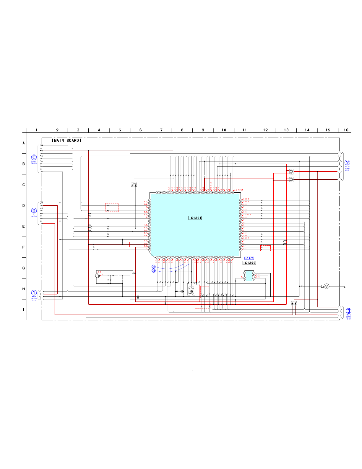
HCD-HPR90/HPR99XM
2323
HCD-HPR90/HPR99XM
6-8. SCHEMATIC DIAGRAM – MAIN Section (1/3) –
• See page 36 for Waveforms. • See page 37 for IC Block Diagrams. • See page 44 for IC Pin Function Description.
R
13
1
1
R
1313
R
1
316
R
13
19
R
132
0
R
13
23
R
132
4
R1
3
25
R
1326
R
13
2
8
R1402
R
14
17
R
1
423
R
142
6
R1456
CN1306
R1486
R1487
R1391
R1392
R1393
R1394
R1395
R1401 C1404
R
13
75
R
1474
R
13
73
R
13
72
R
1371
R
1
37
0
R
1369
R
1368
R
136
7
R
13
66
C1
36
2
R
13
57
R1
356
R
135
5
R
135
4
R1
3
53
R1343
R1344
R1345
R1346
R1347
R1348
R1349
R1350
R1337
R1336
R1335
R1334
R1333
R1434
R1433
D1201
R1
301
R
1302
R
13
03
R
130
4
R
130
5
R
1
30
6
R
13
07
C131
6
R
1
30
9
X
13
01
C1311
C
1
310
R
14
24
R1
425
R142
8
R
142
9
R
1
430
R1412
D1305 C1403
D1202
C1218
EP1202
R1352
R1332
R1331
IC1302
R
14
18
R1318 R1321
C1402
R1383
R1400
Q1301
CN1305
R1421
R
1
322
R
1427
R
13
27
R1491
R1492
R1493
R1385
R1388
D1303
R1500
R1497
R1397
IC1301
C1312
X1302C1301
R1420
D1203
C1401
22
0k
0
0
10
0
47k
100
100
10
0
100
100
47k
10k
1
0k
1
0k
10k
9P
10k
10k
100
100
100
100
100
47k 0.1
1
00
1M
100
10
0
10
0
100
100
10
0
10
0
10
0
0.1
10
0
10
0
1
00
10
0
100
100
100
100
100
100
100
100
100
100
100
100
100
100
10k
10k
MC2836
100
10
0
10
0
10
0
1
00
1
00
100
0.1
10k
32
.768
KH
z
22p
2
2p
1
0k
10k
1
0k
4.7k
4.7k
10k
1SS355 0.1
MC2836
0.1
100
100
100
PST3629NR
0
100 100
0.1
100
100
2SC3052
11P
0
10
0
10k
10
0
10k
10k
10k
100
100
MC2836
10k
0.1
5MHz1000 6.3V
10k
MC2836
0.1
A3
A4
A5
A6
A7
C1
C2
C3
C4
C5
C6
C7
C8
C9
A1
1
2
3
94
95
91
92
93
88
92
23
24
25
26
28
33
34
39
40
41
42
18
19
21
35
36
37
43
44
45
46
47
48
49
50
54
55
56
53
51
4
4
94
95
93
91
58
59
60
61
66
67
68
65
63
69
70
71
72
73
75
38
32
31
5
7
1
2
3
22
27
85
82
83
88
100
∗
∗
DGND
KEY2
FL DATA
FL CLK
FL STB
DGND
LED DSGX
LED DIRECT
SIRCS
+3.3V
LED DSGX
KEY3 RETURN
EVER+3.3V
SIRCS
M
P3 CLK
B
YTE
XCIN
XCOUT
R
ESET
XOUT
XIN
NM
I
CD S
COR
AC CUT
IIC CLK
CD SENS
CD CLK
W
AKE UP KEY
SPEC IN
KEY2
KEY1
VREF
CD DATA
M
P3 DATA IN
M
P3 DATA OUT
FL SCK
FL STB
SW
8
SW
7
SW
6
SW
5
M2+
M2-
M1+
M1-
CD XLT
MP3 ACK
MP3 REQ
MP3 XLAT
MP3 IREQ
CD XRST
CD XTACN
S
T TUNED
DRIVER
MUTE
CD
ST CE
ST DOU
T
ST CLK
ST DIN/STEREO
POW
ER ON/OFF
S-M
ASTER PG M
U
TE
S-M
ASTER SOFT M
U
TE
S-MASTER R
ST
S-M
ASTER SD
S-M
ASTER DATA
S-M
ASTER SHIFT
S-M
ASTER LATCH
S-M
ASTER NSP M
UTE
S-M
ASTER INIT
HP MU
TE
LIN
E M
UTE
AM
P SI
AM
P SC
EEPROM SDA
EEPROM SCL
STANDBY LED
KEY3
VOLUME
JOG
AUDIO IN
DETECT
+6.2V
LED STANDBY
JOG
VOLUME
KEY3-1
KEY1
CDM SD
SEL B
SEL INH
AC DET
(CHASSIS)
(1/3)
VCC
VSS
VSS
VCC
AVSS
AVCC
SEL
A
FL
SD
IIC DATA
NO USE
SYSTEM CONTROLLER
RESET SWITCH
∗R1497
RESET SIGNAL GENERATOR
C
NVSS
(HPR99XM)
XM
XM
RXD
TXD
E1/SW2
E2/SW1
E3/SW
3
D
LM
5B DISC SENS
RDS DATA/XM
DISC
RST
(HPR90)
(HPR99XM)
XM POWER 3.3V
XM POWER 5V
XM DTIC CMD
(HPR99XM)
(HPR90:US,CND,E,E51,MX,AR/HPR99XM)
DGND
470(HPR90:E,E51,MX,AR)
1k(HPR90:US,CND/HPR99XM)
∗R1397
0(HPR90:SP,AUS)
4.7k(HPR90:US,CND,E,E51,MX,AR/HPR99XM)
M30624MGP-A58FPU0(HPR99XM)
M30622MEP-A39FPU0(HPR90)
R
DS INT/XM
DISC IRQ
DLM
5B E0
GND
VDD
OUT
NC
CD
(Page
32)
(Page
33)
(Page
25)
(Page
24)
(Page
25)
Ver. 1.1
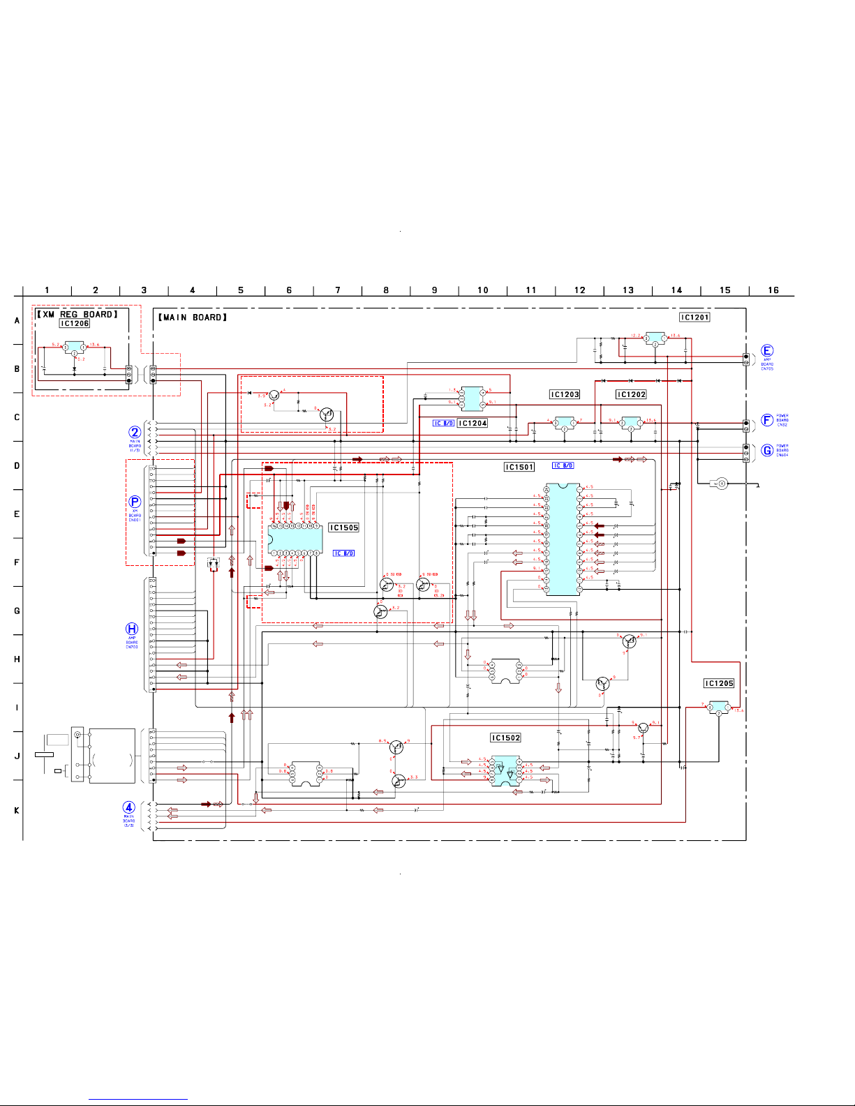
HCD-HPR90/HPR99XM
2424
HCD-HPR90/HPR99XM
Q1501
R1520
R1518
IC1501
IC1203 IC1202
IC1201
IC1502
Q1508
Q1503 Q1504
C1213
R1558
R1559
R1513
R1202
R1506
R1556
R1501 R1551
R1502
R1552
R1363R1361
R1521
R1519
R1515
R1565
R1554
R1503
R1553
R1557
R1510 R1560
R1201
R1203
C1207
C1205
C1212
C1209
C1201
C1203
C1563
C1562
C1561
C1555
C1504
C1513
C1512
C1511
C1505
C
1502
C1558
C1508
C1532
C1565
C1515
C1552
C1507
EP1201
Q1502
CN1203
CN1202
CN1201
Q1509
IC1204
C1501
C1522
C1521
C1520
C1523
C1519
C1518
C1503
C1208
C1206
C1531
C1202C1217
C1204
R1504
C1550
IC1503
R1555
Q1510
C1506
R1512
R1511
R1575
IC1504
Q1505
R1514 R1516
IC1505
R1523C1526
JW1612
R1507 C1517
R1505
JW1613
C1567
IC1205
C1211
C1509C1559
R1525
CN1310
C1576
R1573
D1208D1209D1210D1213
D1204
D1205
Q1602
R1605
R1606
Q1601
CN1301
CN1302
CN1205
C1210D1214
IC1206
C1215
CN1204
R1550
JR1502
JR1501
RT1N141C
220k
220k
BD3870FS
TA7804LS TA7809S
NJM4580MD
RT1N141C
RT1N141C RT1N141C
0.01
2.2k
2.2k
2.2k
10k
10k
10k
220 220
10k
10k
00
10k
10k
100k
100k
4.7k
1k
1k
47
100k 100k
100k
22k
470
10V
470
10V
470
10V
220
10V
2200
25V
470
16V
1 50V
1 50V
10 50V
10 50V
220
10V
1 50V
1 50V
10 50V
10 50V
220
10
V
10
50V
10
50V
100
16V
10
50V
10
50V
100
16V
100 16V
RT1P141C
2P
2P
3P
RT1P141C
MM1615ANLE
0.1
0.0022
0.1
0.1
0.0022
0.1
0.1
0.1
0.1
0.1
0.1
0.10.01
0.1
4.7k
220
16V
RT3C55M
22k
2SC3052
0.1
10k
10k
1k
RT3C55M
RT1N141C
2.2k 10k
MC14052BDTR2
100k1
50V
47 220 10V
22k
220 10V
TA7807S
0.1
1
50V150V
1k
9P
1
50V
100k
1N4002B1N4002B1N4002B1N4002B
MC2836
1SS355WTE-17
2SA1235
10k
1k
RT1N141C
15P
19P
3P
0.111EQS04
TA7805S
220
10V
3P
4.7k
0
0
A3
A4
A5
A6
A7
B1
B2
B3
B4
B5
A1
60
61
63
58
51
59
65
C1
C2
A1
A2
B1
B2
C1
C2
56
55
54
53
66
67
68
69
70
71
72
73
75
83
32
31
85
18
21
82
SC
VIN1
SEL1
VIN2
SEL2
A1
A2
B1
B2
C1
C2
FILTER
GND
SI
VCC
CAP
OUT2
OUT1
BOUT2
BNF2
BOUT1
BNF1
TNF2
TNF1
12V
GND
GND
GND
DO/STEREO
ST CLK
ST DIN
ST CE
R OUT
AGND
L OUT
+9V
4V(SUB)
NC
C2
B2
E2
E1
B1
C1
C2
B2
E2
E1
B1
C1
IN
H
V
EE
G
N
D
VC
C
Y0
Y
2
Y
Y
3
Y
1
B
A
X
3
X
0
X
X
1
X2
VO
VI
CONT
GND
NOISE
POWER ON/OFF
(CHASSIS)
(2/3)
+12V REGULATOR
G
IO
IO
G
IO
G
+9V REGULATOR+4V REGULATOR
+5V REGULATOR
INPUT SELECTOR,ELECTRICAL VOLUME,
SURROUND/TONE CONTROL
+7V REGULATOR
IGO
Q1501,1502
MUTING CONTROL
SWITCH
MUTING
HEADPHONE AMP
GND
VCC
RIPPLE FILTER
Q1508,1509
MUTING CONTROL SWITCH
MUTING
INVERTERINVERTER
INVERTER
SELECT SWITCH
/OTW
OVF
/RST
DGND
/SD
DGND
INIT
D+3.3V
AGND
AGND
A+5V
PGMUTE
SOFTMUTE
SCDT
SCSHIFT
SCLATCH
NSPMUTE
L-IN
R-IN
AM
ANTENNA
COAXIAL
THE ASSEMBLED
BLOCK
SUPPLIED WITH
TUNER
(FM/AM)
14V
(HPR99XM)
TUNER/XM
(H
PR
90)
(H
PR
9
0)
Q1601,1602
B+ SWITCH
RST#
ERR-IRQ#
CDM-SEL
DGND
DGND
SC-RX-IN
SC-TX-OUT
+9V
R-OUT
AGND
L-OUT
(HPR99XM)
(HPR99XM)
(HPR99XM)
OI
G
+4V REGULATOR
XM DVCC +5V
XM AVCC +5V
XM PWR +3.3V
XM POWER
µPC2912HF
FM75
Ω
6-9. SCHEMATIC DIAGRAM – MAIN Section (2/3) –
(Page 29)
(Page 35)
(Page 35)
• See page 37 for IC Block Diagrams.
(Page
23)
(Page
27)
(Page
29)
(Page 25)
 Loading...