

Sony HCD-HP8V Service Manual
HCD-HP8V
E Model
SERVICE MANUAL
MICRO HI-FI COMPONENT SYSTEM
Sony Corporation
Home Audio Company
Published by Sony Engineering Corporation
9-877-476-01
2003G1678-1
© 2003.07
HCD-HP8V is the Amplifier, CD player, Tape
Deck and Tuner section in CMT-HP8V.
SPECIFICATIONS
Ver 1.0 2003.07
Model Name Using Similar Mechanism NEW
CD
CD Mechanism Type CDM69BH-30BD62
Section
Base Unit Name BU-30BD62
Optical Pick-up Name A-MAX.3
TAPE
Model Name Using Similar Mechanism HCD-EP515
Section
Tape Transport Mechanism Type CMAL1Z234A
Tape deck section
Recording system 4-track 2-channel, stereo
Frequency response 50 – 13,000 Hz (±3 dB),
using Sony TYPE I
cassettes
Tuner section
FM stereo, FM/AM superheterodyne tuner
FM tuner section
Tuning range 87.5 – 108.0 MHz
AntennaFM lead antenna
Antenna terminals 75 ohms unbalanced
Intermediate frequency 10.7 MHz
AM tuner section
Tuning range
Middle Eastern model: 531 – 1,602 kHz
(with the tuning interval
set at 9 kHz)
Other models: 530 – 1,710 kHz
(with the tuning interval
set at 10 kHz)
531 – 1,602 kHz
(with the tuning interval
set at 9 kHz)
Antenna AM loop antenna
Antenna terminals External antenna terminal
Intermediate frequency 450 kHz
Main unit
Amplifier section
The following measured at AC 120, 127, 220, 240 V
50/60 Hz
DIN power output (rated): 60 + 60 watts (6 ohms at 1
kHz, DIN)
Continuous RMS power output (reference):
60 + 60 watts (6 ohms at 1
kHz, 10% THD)
Inputs
MD IN (phono jacks): Sensitivity 250 mV,
impedance 47 kilohms
MIC (phone jack): Sensitivity 1 mV,
impedance 10 kilohms
Outputs
PHONES (stereo minijack):
Accepts headphones of 8
ohms or more
MD OUT (phono jack): Impedance 1 kilohm
VIDEO OUT (phono jack):
Max. output level 1Vp-p,
unbalanced, Sync
negative, load impedance
75 ohms
SPEAKER: Accepts impedance of 6 to
16 ohms.
CD player section
System Compact disc and digital
audio system
Laser Semiconductor laser
(λ=780 nm)
Emission duration:
continuous
Frequency response 2 Hz – 20 kHz (±0.5 dB)
Wavelength 780 – 790 nm
Signal-to-noise ratio More than 90 dB
Dynamic range More than 90 dB
Video color system format
NTSC, PAL

2
HCD-HP8V
SAFETY-RELATED COMPONENT WARNING!!
COMPONENTS IDENTIFIED BY MARK 0 OR DOTTED LINE WITH
MARK 0 ON THE SCHEMATIC DIAGRAMS AND IN THE PARTS
LIST ARE CRITICAL TO SAFE OPERATION. REPLACE THESE
COMPONENTS WITH SONY PARTS WHOSE PART NUMBERS
APPEAR AS SHOWN IN THIS MANUAL OR IN SUPPLEMENTS
PUBLISHED BY SONY.
General
Power requirements
Saudi Arabian model: 120 – 127/220 or 230 – 240
V AC, 50/60 Hz
Adjustable with voltage
selector
Other models: 120 V, 220 V or 230 – 240
V AC, 50/60 Hz
Adjustable with voltage
selector
Power consumption: 100 watts
Dimensions (w/h/d) Approx. 199 × 252 × 400
mm
Mass Approx. 7.5 kg
Supplied accessories: Remote commander (1)
Batteries (2)
AM loop antenna (1)
FM lead antenna (1)
Speaker pads (8)
Video cable (1)
Design and specifications are subject to change
without notice.

3
HCD-HP8V
1. SERVICING NOTES ······················································· 4
2. GENERAL ·········································································· 6
3. DISASSEMBLY
3-1. Case (Side-L)(Side-R),
Tape Mechanism Deck (CMAL1Z234A) ······················ 9
3-2. Front Panel Section ······················································· 9
3-3. Panel Board ································································· 10
3-4. Back Panel Section ······················································ 10
3-5. MAIN Board ······························································· 11
3-6. PWR AMP Board, Power Transformer ······················· 11
3-7. CD Mechanism Deck (CDM69BH-30BD62) ············· 12
3-8. JACK Board, VMP Board ··········································· 12
3-9. Base Unit Section ························································ 13
3-10.Base Unit (BU-30BD62) ············································· 13
3-11.BD Board ····································································· 14
3-12.SW Board, Bracket (Top) Assy ··································· 15
3-13.CONNECTOR Board ·················································· 15
3-14.Motor (Stocker) Assy (Stocker)(M761) ······················ 16
3-15.Motor (Roller) Assy (Roller)(M781)··························· 16
3-16.Motor (Mode) Assy (Mode)(M771) ···························· 17
3-17.Rubber Roller (Slider) Assy ········································ 17
3-18.Timing Belt (Front/Rear) ············································· 18
3-19.Cam (Gear) ·································································· 18
3-20.SENSOR Board ··························································· 19
4. ASSEMBLY
4-1. How to Install the Cam (Eject Lock) ···························· 20
4-2. How to Install the Cam (GEAR)··································· 20
4-3. How to Install the Gear (MODE C) ······························21
4-4. How to Install the Gear (MODE CAM) ······················· 21
4-5. How to Install the Rotary Encoder (S702),
Gear (STOCKER COMMUNICATION) ····················· 22
4-6. How to Install the Stocker Assy ····································22
5. TEST MODE ···································································· 23
6. MECHANICAL ADJUSTMENTS ····························· 24
7. ELECTRICAL ADJUSTMENTS ·······························25
8. DIAGRAMS······································································ 28
8-1. Block Diagram — CD SERVO Section — ················· 30
— AUDIO/VIDEO Section — ···································· 31
— MAIN Section — ··················································· 32
8-2. Printed Wiring Boards — BD Section — ··················· 33
8-3. Schematic Diagram — BD Section — ························ 34
8-4. Printed Wiring Boards — VMP Section (1/2) —········ 35
8-5. Printed Wiring Boards — VMP Section (2/2) —········ 36
8-6. Schematic Diagram — VMP Section (1/2) — ············37
8-7. Schematic Diagram — VMP Section (2/2) — ············38
8-8. Printed Wiring Boards — Changer Section — ··········· 39
8-9. Schematic Diagram — Changer Section — ················ 40
8-10.Printed Wiring Boards — Main Section —················· 41
8-11.Schematic Diagram — Main Section — ····················· 42
8-12.Printed Wiring Boards — Front Section — ················ 43
8-13.Schematic Diagram — Front Section — ·····················44
8-14.Printed Wiring Boards
— PWR AMP/Power Section —································· 45
8-15.Schematic Diagram
— PWR AMP/Power Section —································· 46
8-16.IC Block Diagrams ······················································ 47
8-17.IC Pin Function Description ········································ 50
9. EXPLODED VIEWS
9-1. Case, Top Panel Section ·············································· 57
9-2. Front Panel Section ····················································· 58
9-3. Chassis Section-1 ························································ 59
9-4. Chassis Section-2 ························································ 60
9-5. CD Mechanism Section-1 (CDM69BH-30BD62) ······ 61
9-6. CD Mechanism Section-2 (CDM69BH-30BD62) ······ 62
9-7. CD Mechanism Section-3 (CDM69BH-30BD62) ······ 63
9-8. CD Mechanism Section-4 (CDM69BH-30BD62) ······ 64
9-9. CD Mechanism Section-5 (CDM69BH-30BD62) ······ 65
9-10.CD Mechanism Section-6 (CDM69BH-30BD62) ······ 66
9-11.Base Unit Section (BU-30BD62) ································ 67
10.ELECTRICAL PARTS LIST ······································· 68
TABLE OF CONTENTS
4
HCD-HP8V
SECTION 1
SERVICING NOTES
CAUTION
Use of controls or adjustments or performance of procedures
other than those specified herein may result in hazardous
radiation exposure.
Notes on chip component replacement
•Never reuse a disconnected chip component.
• Notice that the minus side of a tantalum capacitor may be damaged by heat.
Flexible Circuit Board Repairing
•Keep the temperature of the soldering iron around 270 ˚C during
repairing.
• Do not touch the soldering iron on the same conductor of the
circuit board (within 3 times).
• Be careful not to apply force on the conductor when soldering or
unsoldering.
This appliance is classified as a CLASS 1 LASER product.
This label is located on the rear exterior.
Laser component in this product is capable of emitting radiation
exceeding the limit for Class 1.
NOTES ON LASER DIODE EMISSION CHECK
The laser beam on this model is concentrated so as to be focused on
the disc reflective surface by the objective lens in the optical pickup block. Therefore, when checking the laser diode emission,
observe from more than 30 cm away from the objective lens.
LASER DIODE AND FOCUS SEARCH OPERATION
CHECK
Carry out the “S curve check” in “CD section adjustment” and check
that the S curve waveforms is output three times.
UNLEADED SOLDER
Boards requiring use of unleaded solder are printed with the leadfree mark (LF) indicating the solder contains no lead.
(Caution: Some printed circuit boards may not come printed with
the lead free mark due to their particular size)
: LEAD FREE MARK
Unleaded solder has the following characteristics.
• Unleaded solder melts at a temperature about 40 ˚C higher than
ordinary solder.
Ordinary soldering irons can be used but the iron tip has to be
applied to the solder joint for a slightly longer time.
Soldering irons using a temperature regulator should be set to
about 350 ˚C .
Caution: The printed pattern (copper foil) may peel away if the
heated tip is applied for too long, so be careful!
• Strong viscosity
Unleaded solder is more viscous (sticky, less prone to flow) than
ordinary solder so use caution not to let solder bridges occur such
as on IC pins, etc.
• Usable with ordinary solder
It is best to use only unleaded solder but unleaded solder may
also be added to ordinary solder.
NOTES ON HANDLING THE OPTICAL PICK-UP
BLOCK OR BASE UNIT
The laser diode in the optical pick-up block may suffer electrostatic
break-down because of the potential difference generated by the
charged electrostatic load, etc. on clothing and the human body.
During repair, pay attention to electrostatic break-down and also
use the procedure in the printed matter which is included in the
repair parts.
The flexible board is easily damaged and should be handled with
care.
5
HCD-HP8V
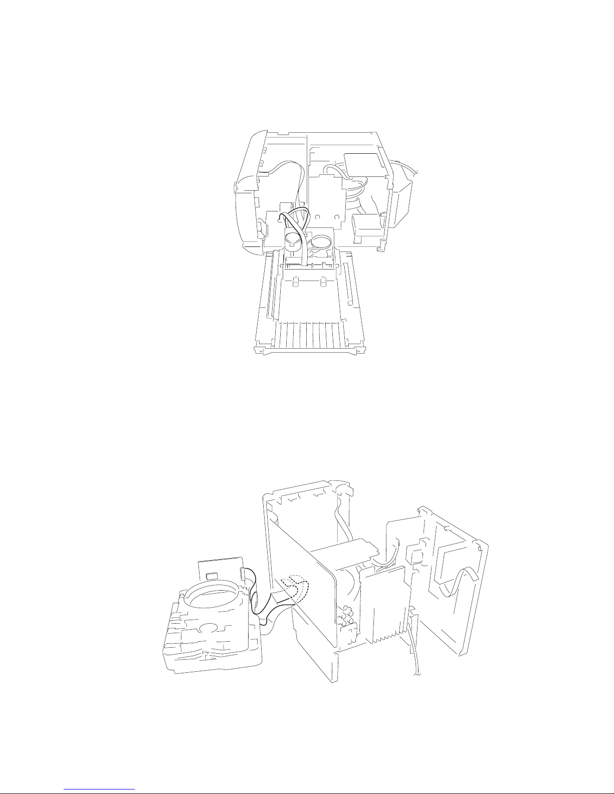
Service Position of the Tape Cassette Mechanism Deck
Service Position of the CD Mechanism Deck
6
HCD-HP8V
SECTION 2
GENERAL
This section is extracted
from instruction manual.
Main unit
CD SYNC 9 (18)
DIMMER ws (25)
DISC 1 – 5 qs (10, 13, 32)
Disc slot qf
DISPLAY 6 (24, 25, 32)
Display window 3
ECHO LEVEL qg (21)
FUNCTION wd (9, 1 1, 13, 16, 18,
19, 28)
GROOVE w; (20)
MIC jack qj
MIC LEVEL qh (21)
PHONES jack qd
PLAY MODE 7 (9, 13, 18, 19,
23)
PRESET EQ wa (20)
PRESET/ALBUM +/– wf (10,
13, 15, 16)
REC PAUSE/START 0 (18, 19,
21)
Remote sensor 2
REPEAT 8 (12)
Tape deck 4
TUNER/BAND 5 (15, 16)
TUNING +/– qa (15, 16)
VOLUME ql (22)
?/1 (power) 1 (7, 8, 16, 22, 23,
32)
m/M (rewind/fast forward)
qa (10, 18)
./> (go back/go forward)
qa (7, 10, 12, 13, 18)
x (stop) 5 (10, 11, 16, 18, 19,
21, 23, 32)
X (pause) 5 (7, 10, 18)
CD N (play) 5 (10, 11, 13, 14,
37)
TAPE nN (play) 5 (18, 19,
23)
DISC 1 Z – DISC 5 Z (eject) qk
(9, 10)
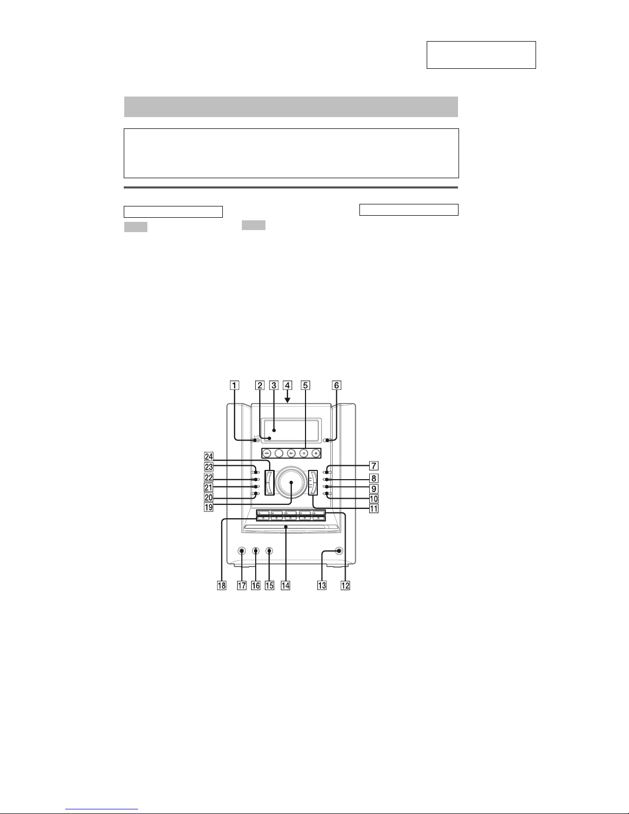
List of button locations and reference pages
How to use this page
Use this page to find the location of buttons and other
parts of the system that are mentioned in the text.
Illustrati
on number
r
TAPE A/B 5 (
18, 19
)
RR
Name of button/part Reference page
ALPHABETICAL ORDER
A – M
P – Z
BUTTON DESCRIPTIONS
7
HCD-HP8V
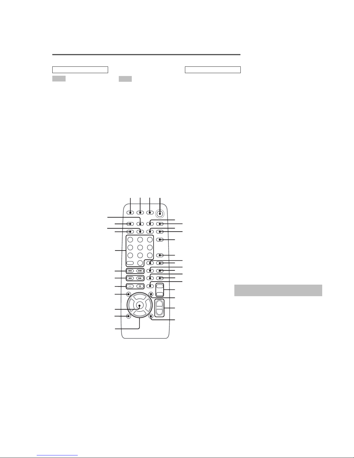
Remote control
ALBUM +/– wh (10, 13)
CD es (9, 11, 13, 16, 18, 19)
CLEAR 9 (13, 14)
CLOCK/TIMER SELECT 2
(23, 24)
CLOCK/TIMER SET 3 (8, 22,
23)
DISPLAY 8 (24, 25, 32)
D. SKIP qa (10, 13)
EFFECT ON/OFF wd (20)
ENTER wf (8, 13, 15, 22, 23)
GAME (MD)
1)
6 (19, 28)
GROOVE wa (20)
KARAOKE/MPX qj (21)
KEY CONTROL
#/2
qk (21)
NEXT wk (11, 14)
Numeric buttons wl (10, 11, 13,
14)
ON SCREEN qs (26)
PLAY MODE e; (9, 13, 18, 19,
23)
PRESET EQ wg (20)
PRESET +/– wk (15, 16)
PREV wk (11, 14)
REPEAT/FM MODE ea (12, 17)
SLEEP 1 (22)
SPECIAL MENU q; (14)
SURROUND ql (20)
TAPE A/B
2)
5 (18, 19)
TUNER BAND ed (15, 16, 19)
TUNER MEMORY 7 (15)
TUNING +/– wj (15, 16)
VOL +/– w; (22)
?/1 (power) 4 (7, 8, 16, 22, 23,
32)
m/M (rewind/fast forward)
wj (10, 18)
./> (go back/go forward)
wk (7, 10, 12, 13, 18)
x (stop) qg (10, 11, 16, 18, 19,
21, 23, 32)
X (pause) qh (7, 10, 18)
N (play) qd (10, 11, 13, 14, 18,
19, 23, 37)
M/m/</, (cursor) ws (8, 22,
23)
RETURN O qf (11)
1)
This button is used to switch
to MD function.
2)
This button is used to switch
to TAPE function.
ALPHABETICAL ORDER
A – N
O – Z
BUTTON DESCRIPTIONS
8
9
q;
qa
12
3
4
5
6
7
qs
qd
qf
qg
qj
ql
w;
wa
ws
wd
wf
wg
wh
wj
wk
wl
e;
ea
es
ed
qk
qh
b
V
v
B
Use buttons on the remote for the operation.
1
Press ?/1 to turn on the system.
2
Press CLOCK/TIMER SET.
3
Press M/m repeatedly to set the hour.
4
Press ,.
5
Press M/m repeatedly to set the
minute.
6
Press ENTER.
The clock starts working.
To adjust the clock
1 Press CLOCK/TIMER SET.
2
Press M/m to select “CLOCK SET”, then
press ENTER.
3
Do the same procedures as step 3 to 6
above.
Notes
•The clock settings are canceled when you disconnect
the power cord or if a power failure occurs.
•You cannot set the clock in Power Saving Mode.
Setting the clock
8
HCD-HP8V
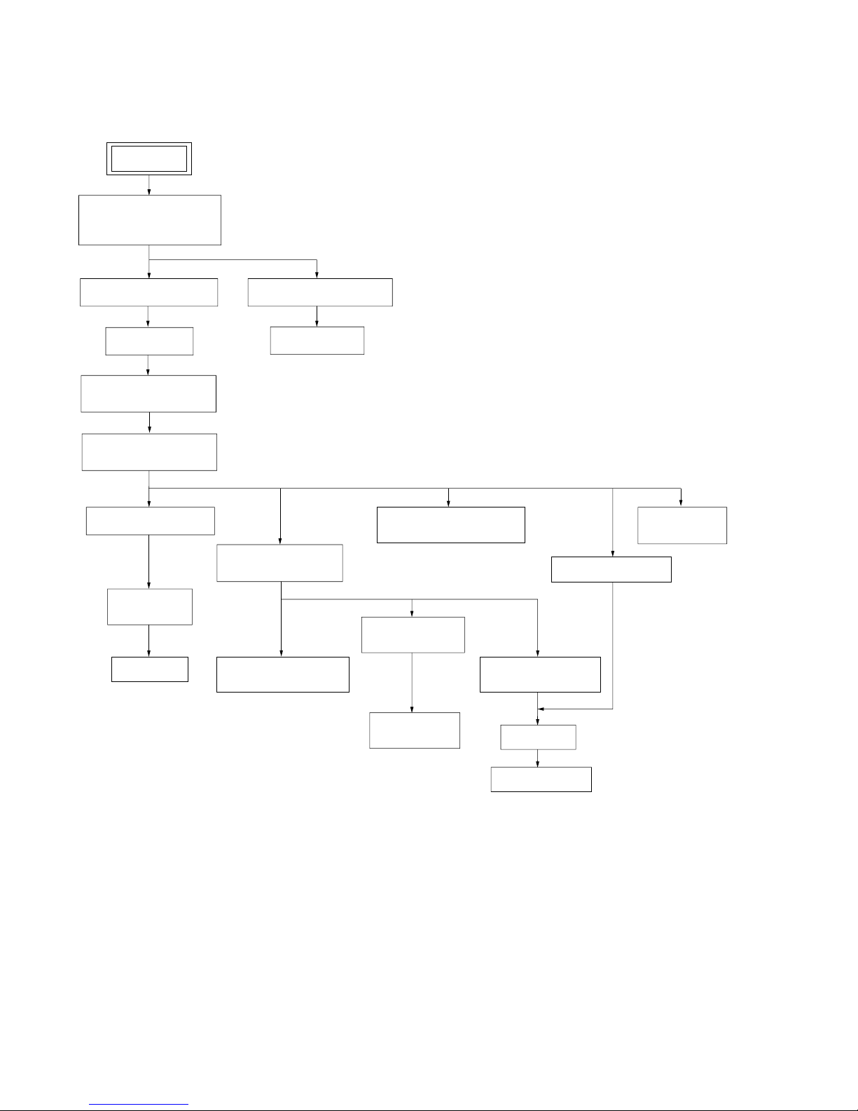
SECTION 3
DISASSEMBLY
• This set can be disassembled in the order shown below.
CD MECHANISM DECK
(CDM69BH-30BD62)
PWR AMP BOARD,
POWER TRANSFORMER
JACK BOARD,
VMP BOARD
FRONT PANEL SECTIONBACK PANEL SECTION
PANEL BOARD
MAIN BOARD
BASE UNIT SECTION
CASE (SIDE-L) (SIDE-R),
TAPE MECHANISM DECK
(CMAL1Z234A))
RUBBER ROLLER
(SLIDER) ASSY
TIMING BELT
(FRONT/REAR)
CAM (GEAR)
SENSOR BOARD
SW BOARD,
BRACKET (TOP) ASSY
BASE UNIT
(BU-30BD62)
MOTOR (MODE)
ASSY (MODE) (M771)
MOTOR (ROLLER)
ASSY (ROLLER) (M781)
MOTOR (STOCKER) ASSY
(STOCKER) (M761)
CONNECTOR BOARD
SET
BD BOARD
9
HCD-HP8V
Note: Follow the disassembly procedure in the numerical order given.
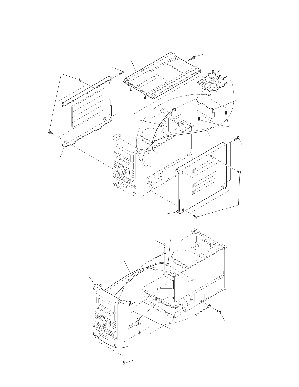
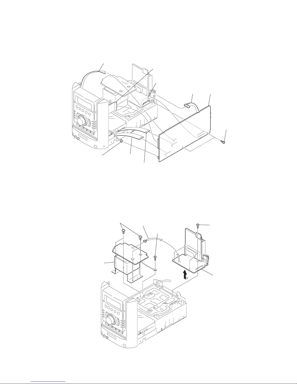
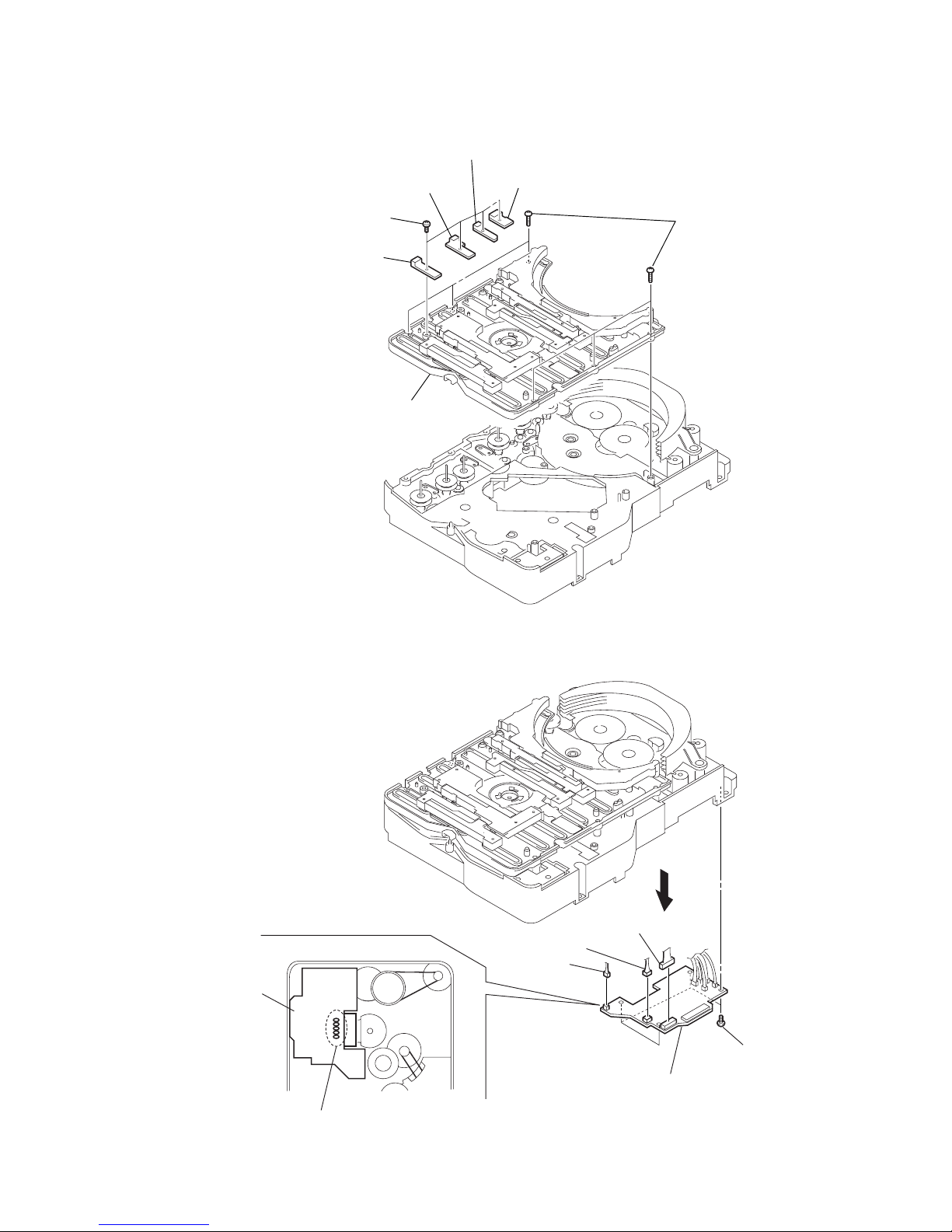
3-1. Case (Side-L)(Side-R), Tape Mechanism Deck (CMAL1Z234A)
3-2. Front Panel Section
9
connector
(6p)
2
two screws
(BVTP3
×
16
)
qa
four screws
(BVTP2.6
×
8)
qs
shield plate (case)
qd
tape mechanism deck
(CMAL1Z234A)
8
top panel section
3
case (side-R)
1
four screws
(case3 TP2)
4
four screws
(case3 TP2)
6
case (side-L)
5
two screws
(BVTP3
×
16
)
7
two screws
(BVTP3
×
16
)
q;
w
ire (flat type) 8p
6
connector
(CN305)
4
connector
(CN405)
1
screw
(BVTP3
×
8
)
7
two screws
(BVTP3
×
8)
3
w
ire (flat type)
9p (CN303)
5
w
ire (flat type)
37p (CN402)
8
front panel section
2
screw
(BVTP3
×
8)
10
HCD-HP8V
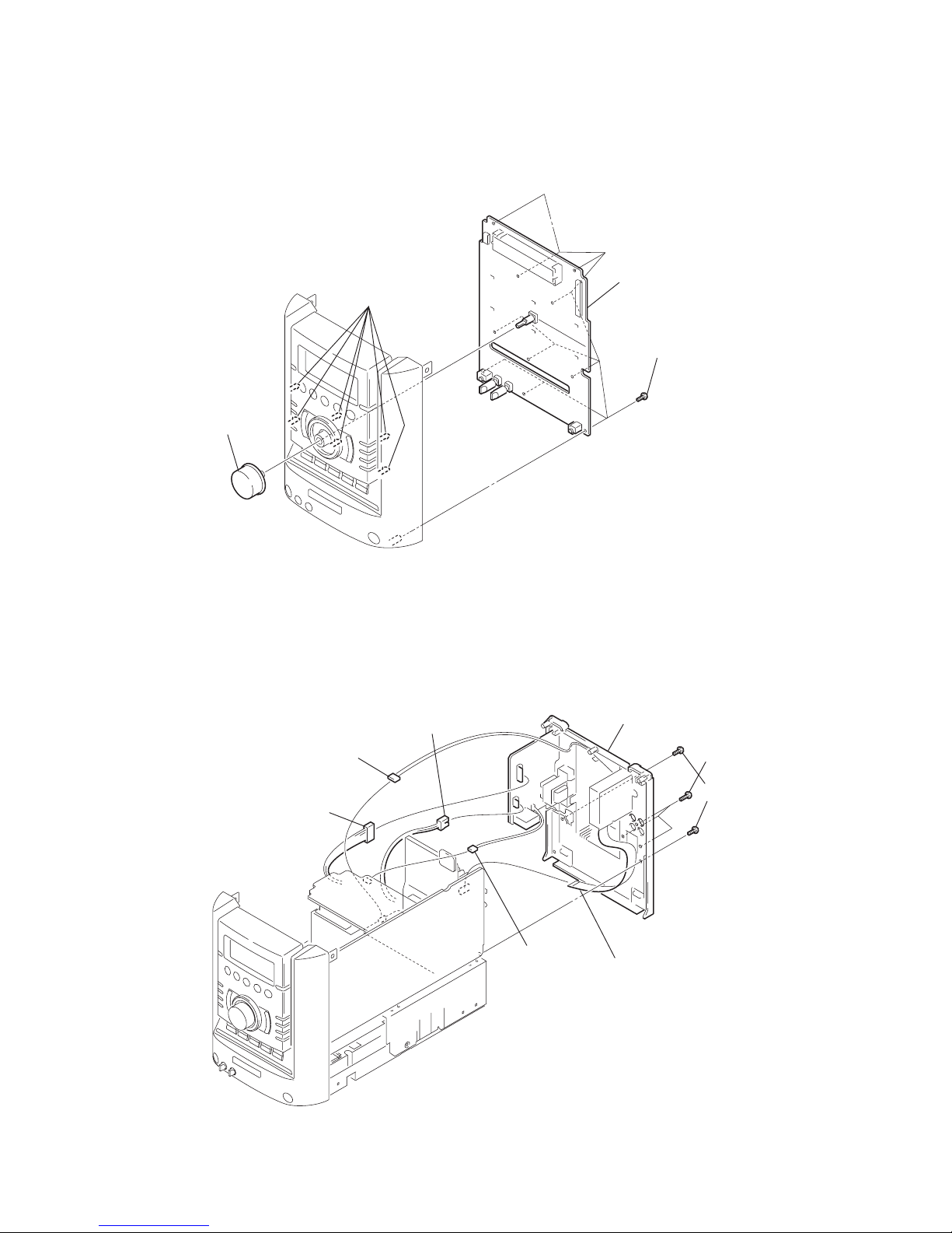
3-3. Panel Board
3-4. Back Panel Section
2
ten screws
(BVTP2.6
×
8)
1
knob
(VOL)
3
six claws
4
PANEL board
8
back panel section
3
two screws
(BVTP3
×
8)
6
connector
(CN908)
5
connector
(CN905)
7
connector
(CN904)
4
connector
(CN503)
1
w
ire (flat type)
11p (CN101)
2
three screws
(BVTP3
×
10
)
11
HCD-HP8V
3-5. MAIN Board
3-6. PWR AMP Board, Power Transformer
3
connector
(CN404)
2
two screws
(BVTP3
×
8
)
9
MAIN board
6
w
ire (flat type)
19p (CN301)
7
w
ire (flat type)
27p (CN302)
1
connector
(CN907)
5
w
ire (flat type)
9p (CN303)
4
w
ire (flat type)
37p (CN402)
8
connector
(CN305)
2
screw
(BVTP3
×
8)
1
connector
(CN902)
3
four screws
(BVTP3
×
8)
4
PWR AMP boar
d
5
four screws
(BVTT4
×
8)
6
power transformer
12
HCD-HP8V
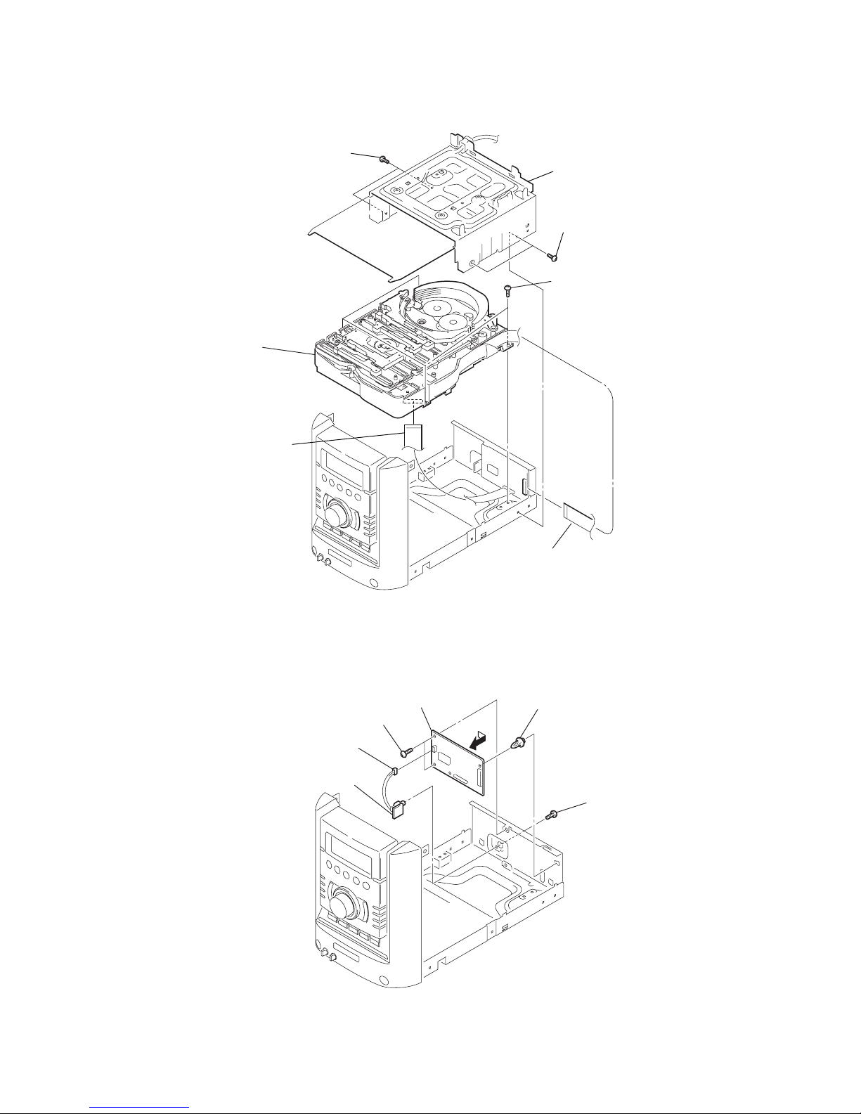
3-7. CD Mechanism Deck (CDM69BH-30BD62)
3-8. JACK Board, VMP Board
5
four screws
(BVTP3
× 8
)
7
CD mechanism deck
(CDM69BH-30BD62)
2
two screws
(BVTP3
×
8
)
1
two screws
(BVTP3
×
8
)
6
w
ire (flat type)
28p (CN101)
4
w
ire (flat type)
19p (CN201)
3
blacket (TR
)
2
screw
(BVTP3
× 8
)
6
support spacer (VMP)
4
two screws
(BVTP3
× 8
)
1
connector
(CN301)
3
JACK board
7
VMP board
5
13
HCD-HP8V
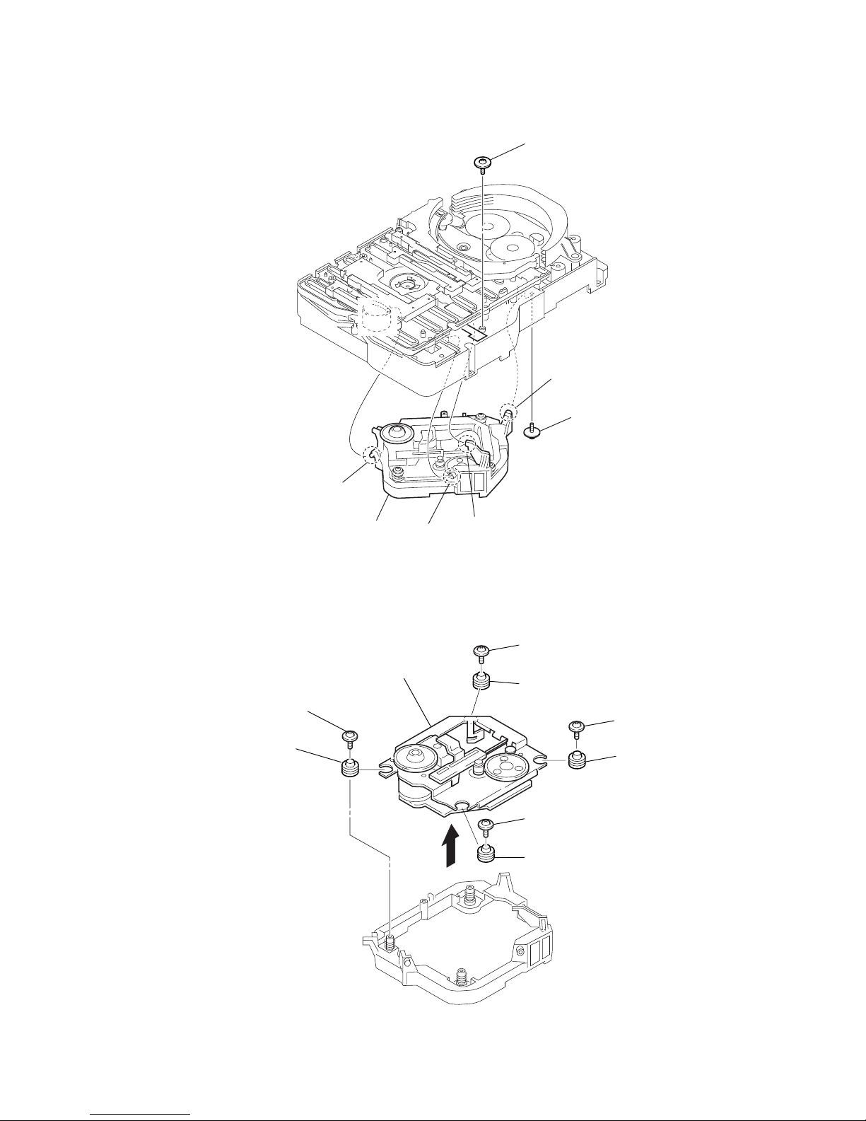
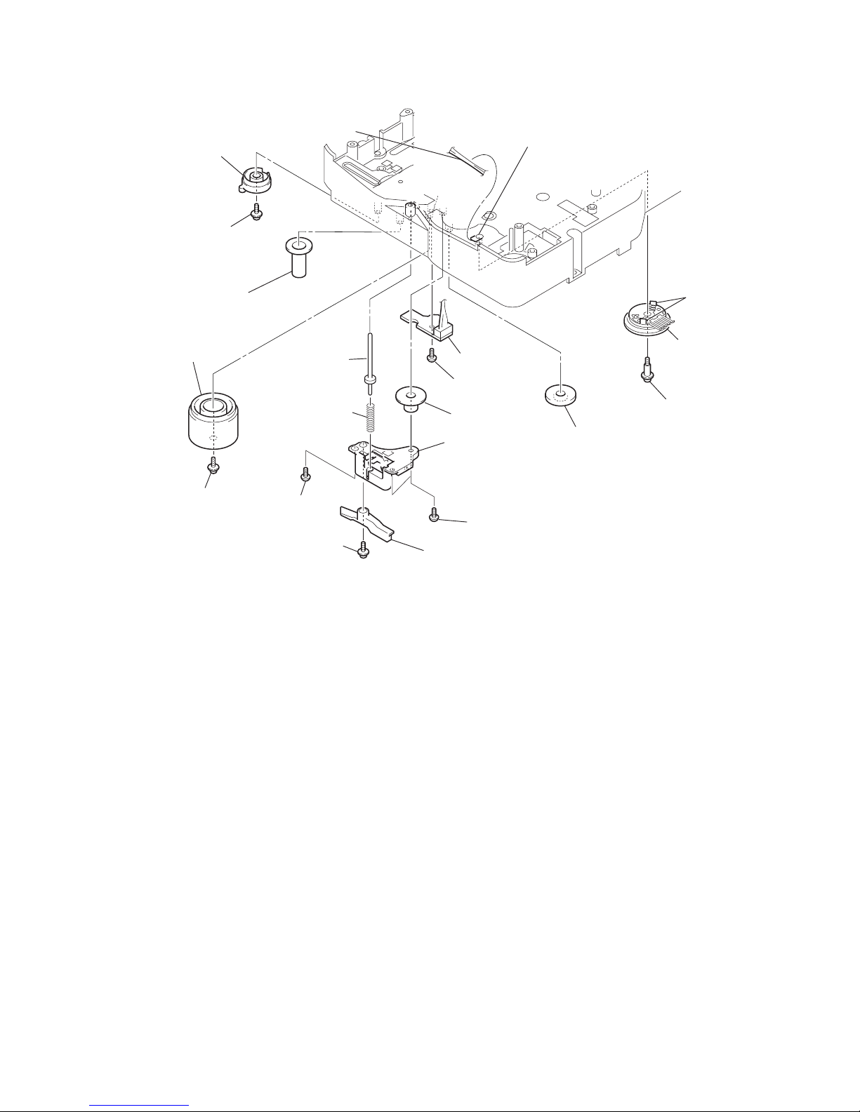
3-9. Base Unit Section
3-10. Base Unit (BU-30BD62)
1
floating
screw
(+PTPWHM2.6)
2
screw
(DIA. 12)
4
boss
6
boss
3
boss
5
boss
7
base unit section
q;
base unit (BU-30BD62)
7
insulator (BU30)
3
floating screw
(+PTPWHM2.6 × 6
)
1
floating screw
(+PTPWHM2.6 × 6)
4
floating screw
(+PTPWHM2.6 × 6)
2
floating screw
(+PTPWHM2.6 × 6)
8
insulator (BU30)
9
insulator (BU30)
6
insulator (BU30)
5
14
HCD-HP8V
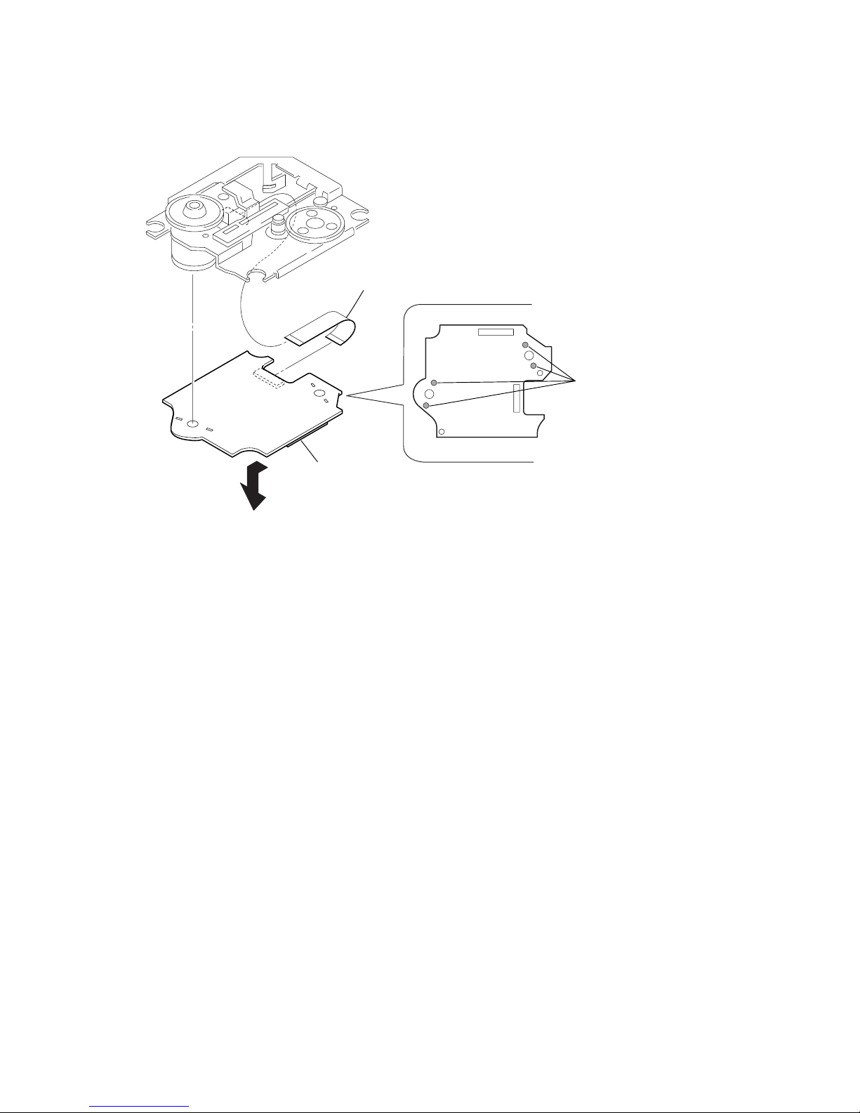
3-11. BD Board
1
Remove the solde
r
(four portions).
3
BD board
2
wire (flat type) (16 core)
15
HCD-HP8V
3-12. SW Board, Bracket (Top) Assy
3-13. CONNECTOR Board
6
six screws
(BVTP2.6
×
8
)
5
SW (4) board
4
SW (3) board
3
SW (2) board
2
SW (1) board
7
bracket (top) assy
1
four
screws
(BTP2.6
×
6)
3
1
Remove five solders.
– bottom view –
CONNECTOR board
2
four screws
(BVTP2.6
×
8)
4
connector
(CN710)
6
connector
(CN703)
5
connector
(CN702)
7
CONNECTOR board
16
HCD-HP8V
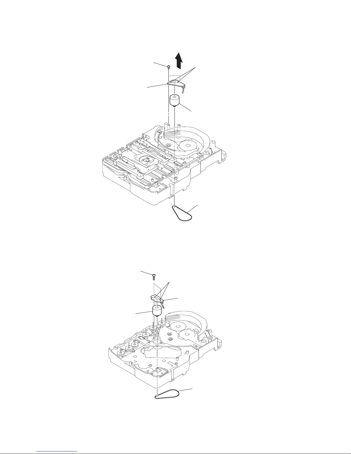
3-14. Motor (Stocker) Assy (Stocker)(M761)
3-15. Motor (Roller) Assy (Roller)(M781)
4
5
STOCKER MOTOR
board
3
two screws
(BVTP2.6
×
8)
2
Remove two solder
s
6
motor (stocker) assy
(stocker) (M761)
1
belt (mode)
1
belt (roller V)
4
ROLLER MOTOR
boar
d
2
Remove two solders.
3
two screws
5
motor (roller) assy
(roller)(M781)
17
HCD-HP8V
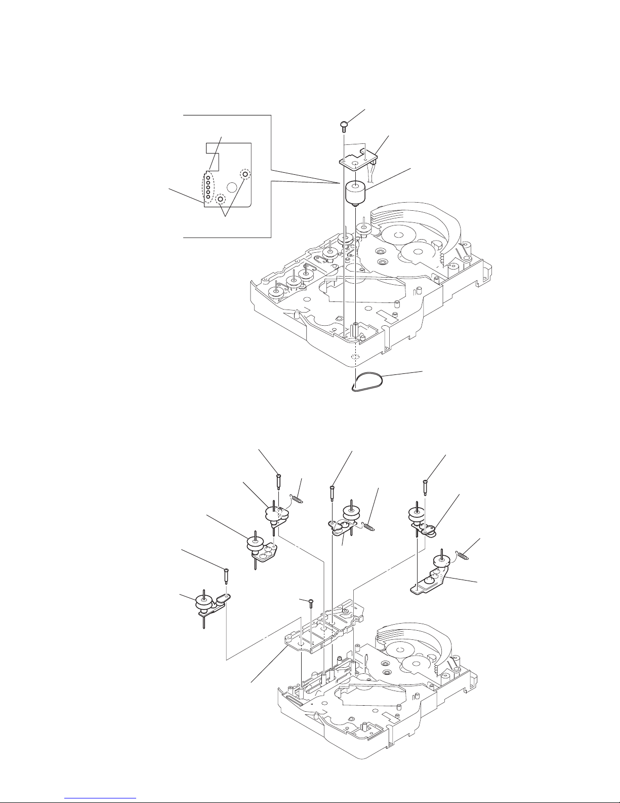
3-16. Motor (Mode) Assy (Mode)(M771)
3-17. Rubber Roller (Slider) Assy
1
Remove five solders
of rotary encoder.
2
Remove two solders
of motor (M771)
MODE MOTOR
board
3
two screws
(BVTP2.6
×
8)
4
MODE MOTOR board
5
belt (mode V)
6
motor (mode) assy
(mode) (M771)
qg
sub chassis
qf
screw
(BVTP2.6
×
8)
8
step screw
qs
step screw
5
step screw
9
tension
spring
(slider 2)
6
tension spring
(base slider 4)
0
rubber roller
(slider 1) assy
7
rubber roller
(slider 1) assy
qa
rubber roller
(slider 2) assy
qd
rubber roller
(slider 4) assy
3
tension spring
(base slider 5
)
1
step screw
4
rubber roller
(slider 5) assy
2
rubber roller
(slider S) assy
18
HCD-HP8V
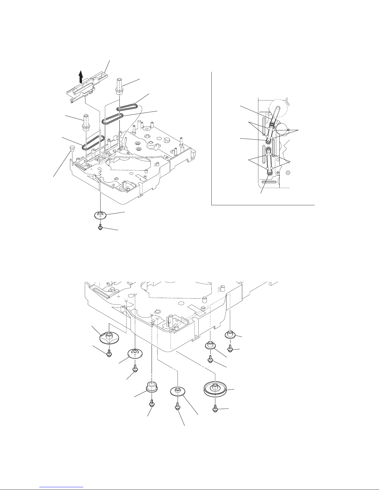
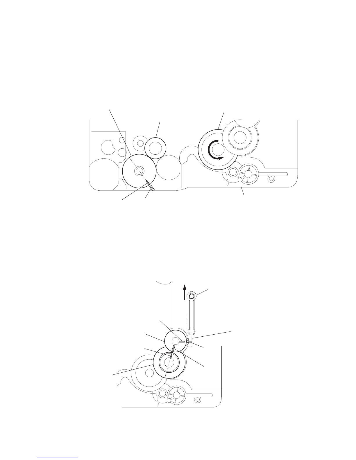
3-18. Timing Belt (Front/Rear)
3-19. Cam (Gear)
Note: Refer to assembly (Section 4)
2
gear (mode cam)
: Note
1
screw
(PTPWH2.6
×
8)
3
slider (mode cam) assy
5
two gears
(center)
7
two gears (center)
8
timing belt (rear)
9
timing belt (rear)
4
gear
(timing)
6
timing belt
(front)
timing belt
(rear)
When install three timing belts,
its pass under each claws.
timing belt
(rear)
timing belt (front)
claw
claw
claw
claw
qf
cam (gear)
: Note
qs
gear(mode cam)
0
gear
(mode C)
:Note
4
gear (mode 5)
8
gear (mode D)
6
gear (mode 5)
1
screw(PTPWH2.6 × 8)
7
screw (PTPWH2.6 × 8)
9
screw
(PTPWH2.6
×
8)
qa
screw
(PTPWH2.6
×
8)
3
screw (PTPWH2.6 × 8)
5
screw (PTPWH2.6 × 8
)
2
pulley
(mode deceleration)
qd
screw
Note: Refer to assembly
(Section 4).
19
HCD-HP8V
3-20. SENSOR Board
ql
harness
qd
gear (eject lock)
q;
cam (eject lock)
: Note
qh
two claws
qj
rotary encoder
(S771)
qf
gear
(mode B)
w;
screw
(BVTP2.6
×
8)
qg
screw
(PTPWH2.6
×
8)
wa
SENSOR board
8
shaft
(shutter)
7
compression spring
(shutter)
qs
cam (BU U/D)
qa
screw
(PTPWH2.6
×
8)
3
screw
(BVTP2.6
×
8)
1
screw
(PTPWH2.6
×
8)
4
two screws
(BVTP2.6
×
8)
2
lever shutter (A)
5
base (shutter) block
6
gear (mode A)
9
screw
(PTPWH2.6
×
8)
qk
claw
Note: Refer to assembly (Section 4).

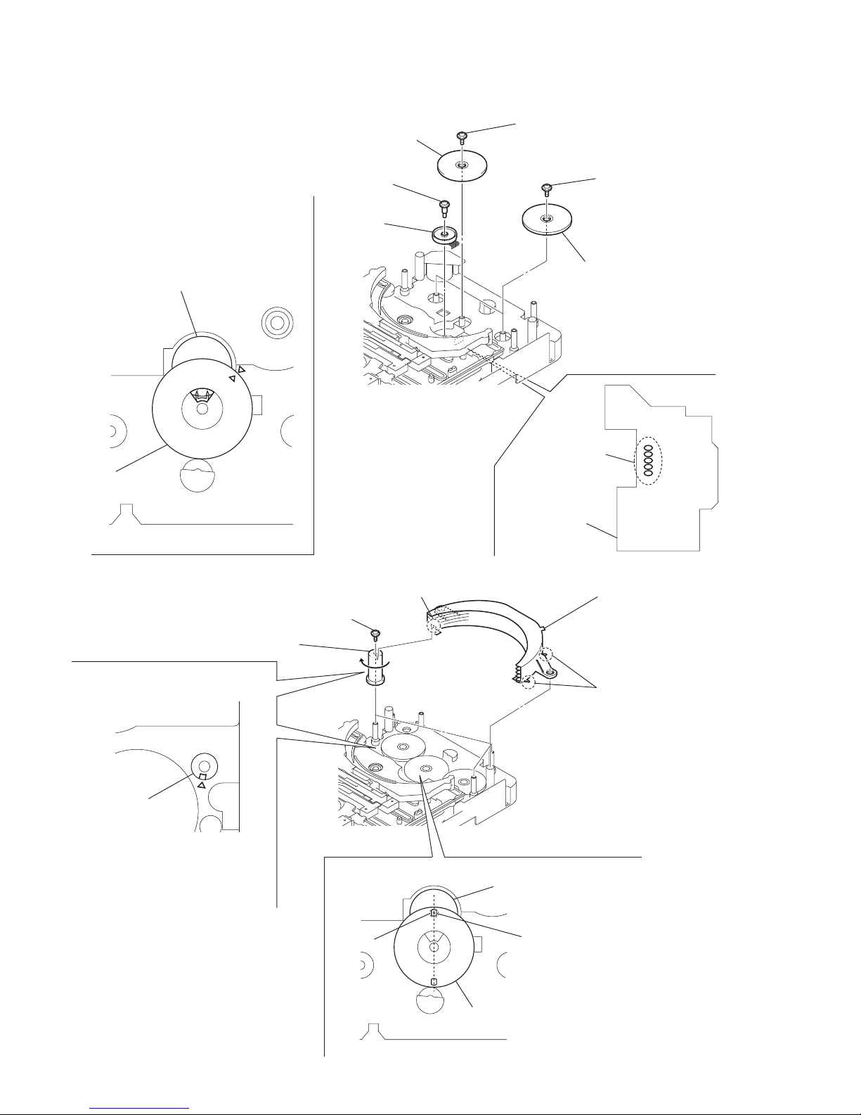
20
HCD-HP8V
• This set can be assembled in the order shown below.
4-1. How to Install the Cam (Eject Lock)
SECTION 4
ASSEMBLY
4-2. How to Install the Cam (Gear)
mark
cam (BU U/D)
cam (eject lock)
– bottom view • front –
gear (eject lock)
1
Rotate the cam (BU U/D) fully in the direction of arrow.
2
Engage the gear (eject lock) and the gear of the cam (eject lock)
aligning the mark with the center of the gear (eject lock).
boss
cam (gear)
mark
cam (BU U/D)
– bottom view • front –
1
Check that the cam (BU U/D) can not be rotated in the direction of arrow.
2
Align the mark on the cam (gear) with the boss as shown in the figure
and install the cam (gear).
21
HCD-HP8V
4-3. How to Install the Gear (Mode C)
4-4. How to Install the Gear (Mode Cam)
1
Align the mark on the rotary encoder (S771) with the projection of the assy.
2
Check that the cam (BU U/D) can not be rotated in the direction of arrow.
3
Install the gear (mode C)
– bottom view • front –
gear (mode C)
rotary encoder
(S771)
cam (BU U/D)
mark projection
chassis
mark
B
slider (mode cam) assy
shaft
mark
A
mark
D
gear (mode cam)
cam (gear)
mark
C
1
Slide the shaft in the direction of arrow.
2
Align mark A on the gear (mode cam) with mark B on the slider (mode cam) assy,
then install the gear (mode cam).
3
Check that mark C on the gear (mode cam) is in alignment with mark D on the cam (gear).
– bottom view • front –
22
HCD-HP8V
4-5. How to Install the Rotary Encoder (S702), Gear (Stocker Communication)
4-6. How to Install the Stocker Assy
2
five
solders
6
two gears
(stocker communication)
4
gear
(stocker communication)
CONNECTOR board
7
two screws
(PTPWH2.6
×
8)
5
screw
(PTPWH2.6
×
8)
3
screw
(PWH2
×
6)
rotary encoder
(S702)
gear
(stocker
communication)
– rear –
1
rotary encoder
(S702)
Engage the rotary encoder (S702)
and the gear (stocker communication)
as shown below in the figure.
2
three cams
(stocker U/D)
3
three screws
(PTPWH2.6
×
8)
boss
boss
rotary encoder
(S702)
Install the stocker assy
fitting three bosses into the
each groove of cam (stocke
r
U/D) then fix by rotating
the cams in the direction
of arrow.
hole
gear
(stocker communication)
– rear –
screw
1
Position the hole on the gear
(stocker communication) on the
screw of the rotary encoder (S702).
To install three cams
(stocker U/D), align each groove
of the cam (stocker U/D)
with each
f
mark on the
chassis as shown in the figure.
cam
(stocker U/D)

23
HCD-HP8V
SECTION 5
TEST MODE
[AM Channel Step 9 kHz/10kHz Selection Mode]
* Either the 9 kHz step or 10 kHz step can be selected for the AM
channel step.
Procedure:
1. Set the function to AM.
2. Press the ?/1 button to turn off the main power.
3. While depressing the TUNER/BAND button, press the ?/1
button to turn on the main power.
4. Either the message “MW 9k STEP” or “MW10k STEP”
appears, and thus the channel step is changed over.
[CD Ship Mode]
*This mode moves the optical pick-up to the position durable to
vibration. Use this mode when returning the set to the customer
after repair.
Procedure:
1. Press the ?/1 button to turn the set on.
2. Press the N (CD) button and the ?/1 button simultaneously.
3. After the message “STANDBY” blinks, “LOCK” is displayed
on the fluorescent indicator tube, and the CD ship mode is set.
[Disc Tray Lock]
The disc tray lock function for the antitheft of an demonstration
disc in the store is equipped.
Setting Procedure:
1. Press the ?/1 button to turn the set on.
2. Press two buttons of x and Z (DISC 1) simultaneously for
five seconds.
3. The message “LOCKED” is displayed and the tray is locked.
Releasing Procedure:
1. Press two buttons of x and Z (DISC 1) simultaneously for
five seconds again.
2. The message “UNLOCKED” is displayed and the tray is
unlocked.
Note : When “LOCKED” is displayed, the tray lock is not released
by turning power on/off with the ?/1 button.
[Cold Reset]
* The cold reset clears all data including preset data stored in the
RAM to initial conditions. Execute this mode when returning the
set to the customer.
Procedure:
1. Press three buttons DISPLAY , x and DISC 1
simultaneously.
2. The fluorescent indicator tube displays the message “COLD
RESET” and the set is reset.
[Version and Destination Display Mode]
*The version or destination is displayed.
Procedure:
1. Press the ?/1 button to turn the set on.
2. To enter the test mode, press the three buttons DISPLAY , x
and DISC 2 simultaneously.
3. The model and destination is displayed. Example : “HPVCD
ASIA3”
4. Press the x and PRESET EQ buttons simultaneously.
5. The version is displayed. Example : “V1.03:2003:02.20”
6. To exit from this mode, press the three buttons DISPLAY , x
and DISC 2 simultaneously, or press the ?/1 button to turn
the set off.
[Panel Test Mode]
* All fluorescent segments, LEDs, keys, volume and headphone
detection are tested.
Procedure:
1. Press the ?/1 button to turn the set on.
2. To enter the test mode, press three buttons DISPLAY , x and
DISC 3 simultaneously. All segments and LEDs are turned
on.
3. Press the x and PRESET EQ buttons simultaneously. In this
key code display mode, the fluorescent indicator displays “KEY
0 0 0”. Each time a button is pressed, the key code is displayed.
4. Press the x and PRESET EQ buttons simultaneously. In this
key count mode, the fluorescent indicator displays “KEYCNT
0 1”. Each time a button is pressed, “KEYCNT 0 X” value
increases. However, once a button is pressed, it is no longer
taken into account.
5. Press the x and PRESET EQ buttons simultaneously. When
a headphone jack is not inserted, “ H_P RELEASE” is
displayed. When a headphone jack is inserted, “ H_P IN” is
displayed.
6. Press the x and PRESET EQ buttons simultaneously. When
the VOLUME knob is not rotated, “VOLUME FLAT” is
displayed. The message “VOLUME UP” is displayed, when
the VOLUME knob is rotated clockwise. The message
“VOLUME DOWN” is displayed, when the VOLUME knob
is rotated counterclockwise.
7. To exit from this mode, press three buttons DISPLAY , x
and DISC 3 simultaneously.
[MC Test Mode]
*This mode is used to check the function of the amplifier.
Procedure:
1. Press the ?/1 button to turn the set on.
2. To enter the test mode, press the three buttons DISPLAY , x
and DISC 4 simultaneously.
3. The message “VOLUME MIN”, “VOLUME 16” or
“VOLUME MAX” is displayed , when turning the VOLUME
knob clockwise or conterclockwise.
4. Each time the DIMMER button is pressed, the message “GEQ
MAX” or “GEQ MIN” is displayed. The function of the
equalizer is set to maximum or minimum.
5. The message “GEQ FLAT” is displayed, when pressing the
PRESET EQ button. The function of the equalizer is set to
flat.
6. Each time the GROOVE button is pressed, the message “VACS
OFF” or “VACS ON” is displayed.
7. Automatic recording/playback : Press the REC button when a
tape is inserted, recording is started and the input source
function is selected to “MD” automatically.
8. When the . button is pressed, tape is rewound , stops at
around the record-starting position and playback is started
automatically.
9. To exit from this mode, press the ?/1 button to turn the set
off.
24
HCD-HP8V
SECTION 6
MECHANICAL ADJUSTMENTS
• TAPE MECHANISM DECK SECTION
Precaution
1. Clean the following parts with a denatured alcohol-moistened
swab:
record/playback heads pinch rollers
erase head rubber belts
capstan idlers
2. Demagnetize the record/playback head with a head
demagnetizer.
3. Do not use a magnetized screwdriver for the adjustments.
4. After the adjustments, apply suitable locking compound to the
parts adjusted.
5. The adjustments should be performed with the rated power
supply voltage unless otherwise noted.
Tor que Measurement
2.94 – 7.84 mN • m
(30 to 79 g • cm)
(0.42 – 1.11 oz • inch)
0.15 – 0.6 mN • m
2 to 6 g • cm
(0.03 – 0.08 oz • inch)
2.94 – 7.84 mN • m
(30 to 79 g • cm)
(0.42 – 1.11 oz • inch)
0.15 – 0.6 mN • m
2 to 6 g • cm
(0.03 – 0.08 oz • inch)
6.86 – 17.64 mN • m
(70 to 179 g • cm)
(0.98 – 2.49 oz • inch)
9.8 mN • m more
(100 • cm or more)
(1.4 oz • inch or more)
9.8 mN • m more
(100 • cm or more)
(1.4 oz • inch or more)
Mode
Tor que meter
CQ-102C
CQ-102C
CQ-102RC
CQ-102RC
CQ-201B
CQ-403A
CQ-403R
Meter reading
FWD
FWD
back tension
REV
REV
back tension
FF/REV
FWD tension
REV tension
[AMP Test Mode]
Procedure:
1Press the ?/1 button to turn the set on.
2. To enter the test mode, press the three buttons x ,
PRESET EQ and DISC 4 simultaneously.
3. The message “AMP TEST IN” is displayed.
4. Press the x and PRESET EQ buttons simultaneously. The
VA CS status and IC parameters are displayed. Example : “D:
S: +4. 0. +2”
5. DBFB ON/OFF Function : Press the GROOVE button, “DBFB
ON” or “DBFB OFF” is displayed.
6. SURROUND ON/OFF Function : Press the PRESET EQ
button, “SURROUND ON” or “SURROUND OFF” is
displayed.
7. To exit from this mode, press three buttons x , PRESET EQ
and DISC 4 simultaneously.
Note: Perform the Cold Reset to initialize the equalizer parameters.
[CD Service Mode]
*This mode can run the CD sled motor freely. Use this mode, for
instance, when cleaning the pickup.
Procedure:
1. Press ?/1 button to turn the set on.
2. Set the function to CD.
3. Press three buttons DISPLAY , x and DISC 5
simultaneously.
4. The MPEG AV TEST mode is selected.
5. When the DIMMER buttons is depressed, the CD service
mode is activated.
6. Press > button to move the pickup to outside track, or
press . button to inside track.
7. To exit from this mode, perform as follows:
1) Move the pickup to the most inside track.
2) Perform the Cold Reset.
Note: Do not run the sled motor excessively, otherwise the gear can
be chipped.
25
HCD-HP8V
SECTION 7
ELECTRICAL ADJUSTMENTS
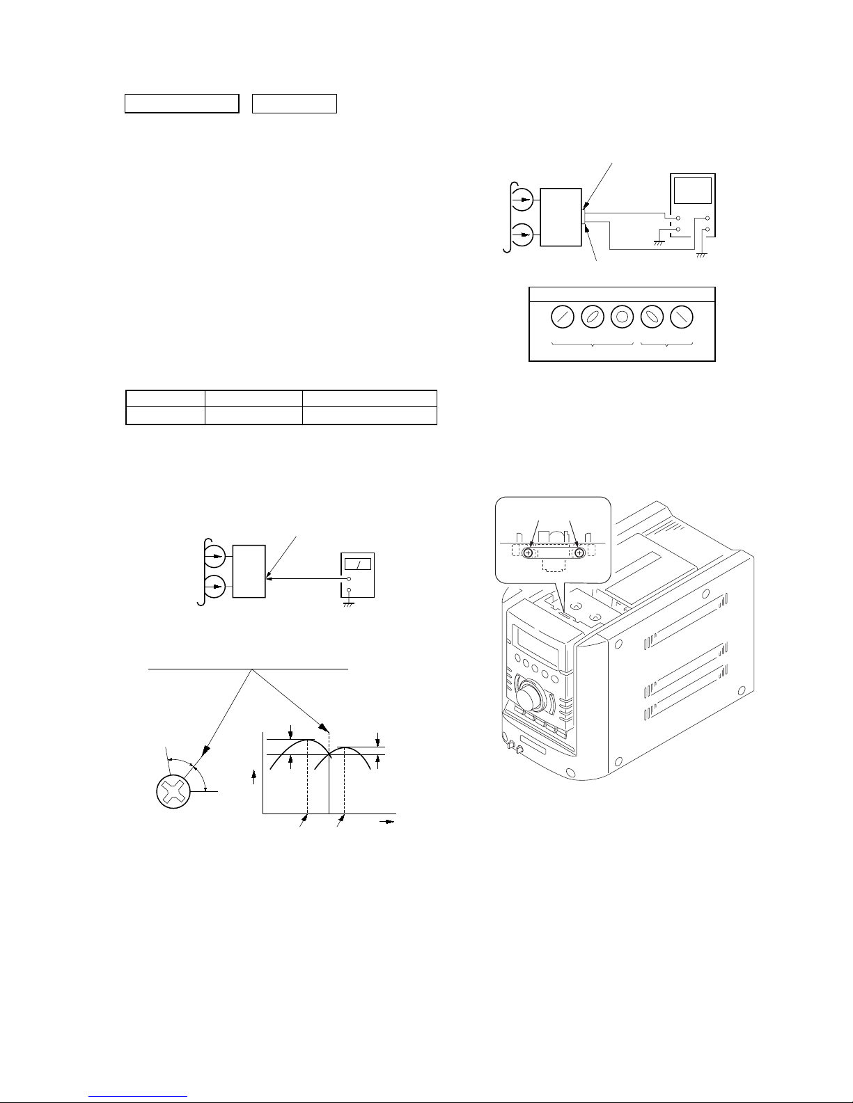
2. Turn the adjustment screw and check output peaks. If the peaks
do not match for L-CH and R-CH, turn the adjustment screw
so that outputs match within 1dB of peak.
0 dB=0.775 V
DECK SECTION
Note: Confirm each contents of this section first of all. If the results are
not satisfied, do the adjustment.
1. Demagnetize the record/playback head with a head
demagnetizer.
2. Do not use a magnetized screwdriver for the adjustments.
3. After the adjustments, apply suitable locking compound to the
parts adjust.
4. The adjustments should be performed with the rated power
supply voltage unless otherwise noted.
5. The adjustments should be performed in the order given in this
service manual. (As a general rule, playback circuit adjustment
should be completed before performing recording circuit
adjustment.)
6. The adjustments should be performed for both L-CH and RCH.
7. Switches and controls should be set as follows unless otherwise
specified.
•Test Tape
Record/Playback Head Azimuth Adjustment
Procedure:
1. Mode: Playback
set
PWR AMP board
SPEAKER terminals (JK501
)
L-CH, R-CH
+
–
level meter
test tape
P-4-A63J
(10 kHz, –10 dB)
Screw
position
L-CH
peak
within
1 dB
Output
level
L-CH
peak
R-CH
peak
within
1 dB
Screw
position
R-CH
peak
Tape Signal Used for
P-4-A63J 10 kHz, –10 dB Azimuth Adjustment
3. Mode: Playback
4. Repeat step 1 to 3 in playback (REV) mode.
5. After the adjustments, apply suitable locking compound to the
pats adjusted.
Adjustment Location : Record/Playback/Erase Head
set
test tape
P-4-A63J
(10 kHz, –10 dB)
R-CH
oscilloscope
L-CH
R-CH
V
H
waveform of oscilloscope
in phase 45°90°135°180
°
good
wrong
PWR AMP board
SPEAKER terminals (JK501
)
L-CH
adjustment screw
 Loading...