

Sony HCD-DZ280, HCD-DZ680, HCD-HDZ284, HCD-HDZ485 Service Manual

HCD-DZ280/DZ680/
HDZ284/HDZ485
SERVICE MANUAL
Ver. 1.2 2010.03
Photo: HCD-HDZ284
• HCD-DZ280/DZ680/HDZ284/HDZ485 are the amplifi er, DVD/CD
and tuner section in DAV-DZ280/DZ680/HDZ284/HDZ485.
This system incorporates with Dolby* Digital and Dolby Pro
Logic (II) adaptive matrix surround decoder and the DTS** Digital
Surround System.
* Manufactured under license from Dolby Laboratories.
Dolby, Pro Logic, and the double-D symbol are trademarks of
Dolby Laboratories.
** Manufactured under license under U.S. Patent #’s:
5,451,942; 5,956,674; 5,974,380; 5,978,762; 6,487,535 & other
U.S. and worldwide patents issued & pending. DTS and DTS
Digital Surround are registered trademarks and the DTS logos
and Symbol are trademarks of DTS, Inc. © 1996-2008 DTS,
Inc. All Rights Reserved.
SPECIFICATIONS
Canadian Model
HCD-HDZ284/HDZ485
AEP Model
UK Model
HCD-DZ280/DZ680
PX Model
HCD-HDZ485
Model Name Using Similar Mechanism HCD-DZ260/DZ270/HDZ278
Mechanism Type CDM85-DVBU102
Optical Pick-up Name KHM-313CAA
Amplifi er Section
Stereo mode (rated) 108 W + 108 W (at 3 ohms,
1 kHz, 1% THD)
DZ280/DZ680/HDZ284:
Surround mode (reference) RMS output power
FL/FR/C/SL/SR*: 142
watts (per channel at 3
ohms, 1 kHz, 10% THD)
Subwoofer*: 140 watts (at
3 ohms, 80 Hz, 10% THD)
HDZ485:
Surround mode (reference) RMS output power
FL/FR/C/SL/SR*: 144
watts (per channel at 3
ohms, 1 kHz, 10% THD)
Subwoofer*: 280 watts (at
1.5 ohms, 80 Hz, 10% THD)
* Depending on the decoding mode settings and the
source, there may be no sound output.
Inputs (Analog) (DZ280/DZ680)
TV (AUDIO IN) Sensitivity: 450/250 mV
AUDIO IN Sensitivity: 250/125 mV
Inputs (Digital) (DZ680/HDZ284/HDZ485)
TV/VIDEO (COAXIAL IN/OPTICAL IN)
Impedance: 75 ohms/ Input Stream: Dolby
Digital 5.1ch/DTS 5.1ch/
Linear PCM 2ch
(Sampling Frequency: less
than 48 kHz)
Inputs (Analog) (HDZ284/HDZ485)
TV/VIDEO (AUDIO IN) Sensitivity: 450/250 mV
AUDIO IN Sensitivity: 250/125 mV
Outputs (Analog)
Phones Accepts low- and high impedance headphones.
Super Audio CD/DVD System
Laser Diode Properties Emission Duration:
Continuous
Laser Output: Less than
44.6μW
* This output is the value measurement at a distance
of 200mm from the objective lens surface on the
Optical Pick-up Block with 7mm aperture.
Signal format system
HDZ284/HDZ485: NTSC
DZ280/DZ680: NTSC/PAL
USB Section (DZ280/DZ680)
(USB) port:
Maximum current: 500 mA
Tuner Section
System PLL quartz-locked digital
synthesizer
FM Tuner section
Tuning range
Canadian, PX models: 87.5 MHz - 108.0 MHz
(100 kHz step)
Other models: 87.5 MHz - 108.0 MHz
(50 kHz step)
Antenna (aerial) FM wire antenna (aerial)
Antenna (aerial) terminals 75 ohms, unbalanced
Intermediate frequency 10.7 MHz
Video Section (DZ280/DZ680)
Outputs VIDEO: 1 Vp-p 75 ohms
R/G/B: 0.7 Vp-p 75 ohms
HDMI OUT: Type A (19
pin)
Video Section (HDZ284/HDZ485)
Outputs VIDEO: 1 Vp-p 75 ohms
COMPONENT:
Y: 1 Vp-p 75 ohms
PB/CB, PR/CR: 0.7 Vp-p
75 ohms
HDMI OUT: Type A (19
pin)
– Continued on next page –
DVD RECEIVER
9-889-391-03
2010C04-1
2010.03
©
Sony Corporation
Audio&Video Business Group
Published by Sony Techno Create Corporation

HCD-DZ280/DZ680/HDZ284/HDZ485
Ver. 1.1
General
Power requirements
Canadian model: 120 V AC, 60 Hz
AEP, UK models: 220 V - 240 V AC, 50/60 Hz
PX model: 110 V - 240 V AC, 50/60 Hz
Power consumption
HDZ485: On: 155 W
Standby: 0.3 W (at the
Power Saving mode)
DZ280/DZ680/HDZ284: On: 150 W
Standby: 0.3 W (at the
Power Saving mode)
Output voltage (DIGITAL MEDIA PORT)
DC 5 V
Output current (DIGITAL MEDIA PORT)
700 mA
Dimensions (approx.) 430 mm × 66 mm × 390 mm
(17 in × 2 5/8 in × 15 3/8 in)
(w/h/d) incl. projecting parts
Mass (approx.) 4.3 kg (9 lb 8 oz)
Supported fi le format
MP3 (MPEG 1 Audio Layer-3)
File Extension: mp3
Bitrate: 32 kbps - 320 kbps
Sampling frequencies: 32/44.1/48 kHz
DZ280/DZ680:
WMA (USB device only)
File Extension: wma
Bitrate: 48 kbps - 192 kbps
Sampling frequencies: 44.1 kHz
AAC (USB device only)
File Extension: m4a
Bitrate: 48 kbps - 320 kbps
Sampling frequencies: 44.1 kHz
DZ280:
DivX
File Extension: avi/divx
Video codec: DivX video
Bitrate: 8 Mbps (MAX)
Frame rate: 30 fps
Resolution: 720 × 576
Audio codec: MP3
MPEG4
File format: MP4 File Format
File Extension: mp4/m4v
Video codec: MPEG4 Simple Profi le
(AVC is not compatible.)
Bitrate: 4 Mbps
Frame rate: 30 fps
Resolution: 720 × 576
Audio codec: AAC-LC (HE-AAC is not
compatible.)
DRM: Not compatible
Design and specifi cations are subject to change
without notice.
SAFETY-RELATED COMPONET WARNING!
COMPONENTS IDENTIFIED BY MARK 0 OR DOTTED LINE
WITH MARK 0 ON THE SCHEMATIC DIAGRAMS AND IN
THE PARTS LIST ARE CRITICAL TO SAFE OPERATION.
REPLACE THESE COMPONENTS WITH SONY PARTS
WHOSE PART NUMBERS APPEAR AS SHOWN IN THIS
MANUAL OR IN SUPPLEMENTS PUBLISHED BY SONY.
ATTENTION AU COMPOSANT AYANT RAPPORT
À LA SÉCURITÉ!
LES COMPOSANTS IDENTIFIÉS PAR UNE MARQUE 0 SUR
LES DIAGRAMMES SCHÉMATIQUES ET LA LISTE DES
PIÈCES SONT CRITIQUES POUR LA SÉCURITÉ DE FONCTIONNEMENT. NE REMPLACER CES COMPOSANTS QUE
PAR DES PIÈCES SONY DONT LES NUMÉROS SONT DONNÉS DANS CE MANUEL OU DANS LES SUPPLÉMENTS
PUBLIÉS PAR SONY.
2
SPECIAL COMPONENT NOTICE
The components identifi ed by mark 9 contain confi dential infor-
mation.
Strictly follow the instructions whenever the components are repaired and/or replaced.
NOTICE POUR COMPOSANTS SPÉCIAUX
Les composants identifi és par la marque 9 contiennent des infor-
mations confi dentielles.
Suivre scrupuleusement les instructions chaque fois qu’un composant est remplacé et / ou réparé.

HCD-DZ280/DZ680/HDZ284/HDZ485
Ver. 1.1
MODEL IDENTIFICATION
– Back Panel –
Model Part No.
DZ280: AEP, UK model
HDZ284: CND model
HDZ485: CND model
HDZ485: PX model
DZ680: AEP, UK model
• Abbreviation
CND : Canadian model
Parts No.
4-113-457-0[]
4-113-457-2[]
4-113-457-6[]
4-113-457-8[]
4-113-459-5[]
SAFETY CHECK-OUT
After correcting the original service problem, perform the following safety check before releasing the set to the customer:
Check the antenna terminals, metal trim, “metallized” knobs,
screws, and all other exposed metal parts for AC leakage.
Check leakage as described below.
LEAKAGE TEST
The AC leakage from any exposed metal part to earth ground and
from all exposed metal parts to any exposed metal part having a
return to chassis, must not exceed 0.5 mA (500 microamperes.).
Leakage current can be measured by any one of three methods.
1. A commercial leakage tester, such as the Simpson 229 or RCA
WT-540A. Follow the manufacturers’ instructions to use these
instruments.
2. A battery-operated AC milliammeter. The Data Precision 245
digital multimeter is suitable for this job.
3. Measuring the voltage drop across a resistor by means of a
VOM or battery-operated AC voltmeter . The “limit” indication
is 0.75 V, so analog meters must have an accurate low-voltage
scale. The Simpson 250 and Sanwa SH-63Trd are examples
of a passive VOM that is suitable. Nearly all battery operated
digital multimeters that have a 2 V AC range are suitable. (See
Fig. A)
To Exposed Metal
Parts on Set
AC
1.5 kΩ0.15 μF
Earth Ground
voltmeter
(0.75 V)
Fig. A. Using an AC voltmeter to check AC leakage.
3

HCD-DZ280/DZ680/HDZ284/HDZ485
Laser component in this product is capable of emitting radiation
exceeding the limit for Class 1.
This appliance is classifi ed as
a CLASS 1 LASER product.
This marking is located on the
rear or bottom exterior.
CAUTION
Use of controls or adjustments or performance of procedures
other than those specifi ed herein may result in hazardous radia-
tion exposure.
NOTES ON CHIP COMPONENT REPLACEMENT
• Never reuse a disconnected chip component.
• Notice that the minus side of a tantalum capacitor may be damaged by heat.
FLEXIBLE CIRCUIT BOARD REPAIRING
• Keep the temperature of soldering iron around 270 °C during
repairing.
• Do not touch the soldering iron on the same conductor of the
circuit board (within 3 times).
• Be careful not to apply force on the conductor when soldering
or unsoldering.
UNLEADED SOLDER
Boards requiring use of unleaded solder are printed with the leadfree mark (LF) indicating the solder contains no lead.
(Caution: Some printed circuit boards may not come printed with
the lead free mark due to their particular size)
: LEAD FREE MARK
Unleaded solder has the following characteristics.
• Unleaded solder melts at a temperature about 40 °C higher
than ordinary solder.
Ordinary soldering irons can be used but the iron tip has to be
applied to the solder joint for a slightly longer time.
Soldering irons using a temperature regulator should be set to
about 350 °C.
Caution: The printed pattern (copper foil) may peel away if
the heated tip is applied for too long, so be careful!
• Strong viscosity
Unleaded solder is more viscous (sticky, less prone to fl ow)
than ordinary solder so use caution not to let solder bridges
occur such as on IC pins, etc.
• Usable with ordinary solder
It is best to use only unleaded solder but unleaded solder may
also be added to ordinary solder.
4

Playable Discs
HCD-DZ280/DZ680/HDZ284/HDZ485
nocIscitsiretcarahCogolcsiDepyT
OEDIVDVD•OEDIVDVD
• DVD-R/DVD-RW in DVD VIDEO
format or video mode
• DVD+R/DVD+RW in DVD VIDEO
format
VR (Video
Recording) mode
DATA CD – • CD-R/CD-RW/CD-ROMin DATA CD
DATA DVD – • DVD-ROM/DVD-R/DVD-RW/
• DVD-R/DVD-RW in VR (Video
Recording) mode (except for DVD-R
DL)
)scsid0.2dna1.1.reV(DCOEDIV•DCOEDIV
• Super VCD
• CD-R/CD-RW/CD-ROM in video CD
format or Super VCD format
DCoiduArepuS•DCoiduArepuS
DCoiduA•DC
• CD-R/CD-RW in audio CD format
format, containing MP3files
image files
MPEG4 video files, and conforming to
ISO 9660
(extended format)
DVD+R/DVD+RW in DATA DVD
format, containing MP3files
image files
MPEG4 video files, and conforming to
UDF (Universal Disk Format)
2)
, DivX video files, and
3)
Level 1/Level 2, or Joliet
2)
, DivX video files, and
1)
,JPEG
1)
,JPEG
1)
MP3 (MPEG1 Audio Layer 3) is a standard format defined by ISO/MPEG for compresses audio data. MP3 files
must be in MPEG1 Audio Layer 3 format.
2)
JPEG image filesmust conform tothe DCF image fileformat. (DCF “Design rule for Camera File system”:Image
standards for digital cameras regulated by Japan Electronics and Information Technology Industries Association
(JEITA).)
GB
6
5

HCD-DZ280/DZ680/HDZ284/HDZ485
3)
A logical format of files and folders on CD-ROMs, defined by ISO (International Organization for
Standardization).
Notes on discs
This product is designed to playback discs that conform to the Compact Disc (CD) standard.
DualDiscs and someofthe music discs encoded withcopyrightprotection technologiesdo notconform
to the Com pact Disc (CD) standard, t herefore, these discs may not be playable by this product.
Example of discs that the system cannot play
The system cannot play the following discs:
• CD-ROM/CD -R/CD-RW other than those recorded in the formats listed on page 6
• CD-ROM recorded in PHOTO CD format
• Data part of CD-Extra
•CDGraphicsdisc
• DVD Audio
• DATA DVD that does not contain MP3 files,JPEG image files, DivX video files, or MPEG4 video
files
• DVD-RAM
•Blu-rayDisc
Also, the system cannot play the following discs:
• A DVD VIDEO with a different region code (page 8)
• A disc that has a non-standard shape (e.g., car d, heart)
• A disc with paper or stickers on it
• A disc that has the adhesive of c el lophane tape or a sticker still left on i t
Note about CD-R/CD-RW/DVD-R/DVD-RW/DVD+R/DVD+RW
In somecases,CD-R/CD-RW/DVD-R/DVD-RW/DVD+R/DVD+RW cannot beplayed on thissystem
due to the recording qual ity or physical condition of the disc, or t he character i st ics of the recording
device and authoring software.
The discwill notplay if ithas not beencorrectly finalized. Form ore information,refer tothe operating
instructions for the recording device.
Note that some playback functions may not work with some DVD+RWs/DVD+Rs, even if they have
been correctly finalized. In this case, view the disc bynormalplayback.Also some DATA CDs/DATA
DVDs created in Packet Write format cannot be played.
About Multi Session CD
• This system can play a Multi Session CD when an MP3 file is contained in the first session. Any
subsequent MP3 fil es recorded in later ses si ons can also be played back.
• This system can play a Multi Session CD when a JPEG image file is contained in the first session.
Any subse quent JPEG image fil es recorde d i n later sessions can also b e played back.
• If MP3 files and JPEG image files in music CD format or video CD format are recorded in the first
session, only the first sess ion will be played back.
GB
7
6

HCD-DZ280/DZ680/HDZ284/HDZ485
Region code
Your syst em has a region code printed on the rear of the u ni t and wil l only play a DVD labeled with
the same region code.
A DVD VIDEO labeled wi ll also play on this system.
If you try to play any other DVD VIDEO, the message [Playback prohibited by area limitations.] will
appear on theTV screen. Depending onthe DVD VIDEO, noregioncode indication may begiven even
though playing the DVD VIDEO is prohibited by area restrictions.
ALL
Note about playback operations of a DVD or VIDEO CD
Some playback operations on a DVD or VIDEO CD may be intentionally set by software producers.
Since this system willplay a DVDor VIDEO CDaccording tothe disc contentsthe softwareproducers
designed, some playback features may not be available. Be sure to read the operating instructions
supplied with the DVD or VIDEO CD.
GB
8
7

HCD-DZ280/DZ680/HDZ284/HDZ485
Self-diagnosis Function
(When letters/numbers appear in the
display)
When the self-diagnosis function is activated to
prevent the systemfrom malfunctioning, a 5character service number (e.g., C 13 50) with a
combination of a let t er and 4 digi t s appears on
the TVscreen or frontpanel display. Inthiscase,
check the following table.
C:13:50
When the version number
appears on the TV screen
When you turn on the system, the version
number [VER.X.XX] (X is a number) may
appear on the TV screen. Although this is not a
malfunction and for Sony service use only,
normal syst em operation will not be possible.
Turn off the system, andthen turnon the system
again to operate.
VER.X.XX
First 3
characters of
the service
number
C 13 The disc is dirty.
C 31 The disc is not inserted correctly.
EXX
(XX is a
number)
Cause and/or corrective action
Clean the disc with a soft cloth
(page 80).
Restart thesystem,then re-insert
the disc correctly.
To prevent a malfunction, the
system has performed the selfdiagnosis function.
Contact your nearest Sony
dealer or local authorized Sony
service facility and give the 5character servicenumber.
Example: E 61 10
Additional Information
GB
89
8

HCD-DZ280/DZ680/HDZ284/HDZ485
TABLE OF CONTENTS
1. SERVICING NOTES ............................................. 10
2. GENERAL .................................................................. 12
3. DISASSEMBLY
3-1. Case ................................................................................ 17
3-2. Front Panel Section ......................................................... 17
3-3. Back Panel Section (DZ680/HDZ485) ........................... 18
3-4. Back Panel Section (DZ280/HDZ284) ........................... 18
3-5. DVD Mechanism Deck ................................................... 19
3-6. POWER Board, USB Board (DZ280/DZ680) ................ 19
3-7. MAIN Board, SPEAKER Board .................................... 20
3-8. IO-SCART Board (DZ280/DZ680),
IO-COMPONENT Board (HDZ284/HDZ485) .............. 20
3-9. Tray ................................................................................. 21
3-10. Belt .................................................................................. 21
3-11. MS-203 Board ................................................................. 22
3-12. Base Unit ......................................................................... 22
3-13. Optical Pick-up ............................................................... 23
4. TEST MODE ............................................................ 24
5. ELECTRICAL ADJUSTMENTS ........................ 30
6. DIAGRAMS
6-1. Block Diagram –RF Section– ......................................... 31
6-2. Block Diagram –VIDEO Section– ................................. 32
6-3. Block Diagram –AUDIO Section– ................................. 33
6-4. Block Diagram –AMP Section– ..................................... 34
6-5. Block Diagram –POWER Section– ................................ 35
6-6. Printed Wiring Board –MAIN Section (1/2)– ................. 38
6-7. Printed Wiring Boards –MAIN Section (2/2)– ............... 39
6-8. Schematic Diagram –MAIN Section (1/10)– ................. 40
6-9. Schematic Diagram –MAIN Section (2/10)– ................. 41
6-10. Schematic Diagram –MAIN Section (3/10)– ................. 42
6-11. Schematic Diagram –MAIN Section (4/10)– ................. 43
6-12. Schematic Diagram –MAIN Section (5/10)– ................. 44
6-13. Schematic Diagram –MAIN Section (6/10)– ................. 45
6-14. Schematic Diagram –MAIN Section (7/10)– ................. 46
6-15. Schematic Diagram –MAIN Section (8/10)– ................. 47
6-16. Schematic Diagram –MAIN Section (9/10)– ................. 48
6-17. Schematic Diagram –MAIN Section (10/10)– ............... 49
6-18. Printed Wiring Board –IO-SCART Section
(DZ280/DZ680)– ............................................................ 50
6-19. Schematic Diagram –IO-SCART Section
(DZ280/DZ680)– ............................................................ 51
6-20. Printed Wiring Board –IO-COMPONENT Section
(HDZ284/HDZ485)– ...................................................... 52
6-21. Schematic Diagram –IO-COMPONENT Section
(HDZ284/HDZ485)– ...................................................... 53
6-22. Printed Wiring Boards –FL JACK, SWITCH Section– ... 54
6-23. Schematic Diagram –FL JACK Section– ....................... 55
6-24. Schematic Diagram –SWITCH Section– ....................... 56
6-25. Printed Wiring Boards –S-AIR-CON (DZ680/HDZ485),
USB (DZ280/DZ680) Section– ...................................... 57
6-26. Schematic Diagram –S-AIR-CON Section
(DZ680/HDZ485)– .......................................................... 58
6-27. Schematic Diagram –USB Section (DZ280/DZ680)– .... 59
6-28. Printed Wiring Board –SPEAKER Section– .................. 60
6-29. Schematic Diagram –SPEAKER Section– ..................... 61
6-30. Printed Wiring Board –POWER Section– ...................... 62
6-31. Schematic Diagram –POWER Section– ......................... 63
7. EXPLODED VIEWS
7-1. Overall Section ............................................................... 77
7-2. Front Panel Section ......................................................... 78
7-3. Chassis Section ............................................................... 79
7-4. DVD Mechanism Deck Section (CDM85-DVBU102) .. 80
8. ELECTRICAL PARTS LIST .............................. 81
9

HCD-DZ280/DZ680/HDZ284/HDZ485
SERVICING NOTES
SECTION 1
NOTES ON HANDLING THE OPTICAL PICK-UP
BLOCK OR BASE UNIT
The laser diode in the optical pick-up block may suffer electrostatic break-down because of the potential difference generated by the
charged electrostatic load, etc. on clothing and the human body.
During repair, pay attention to electrostatic break-down and also
use the procedure in the printed matter which is included in the
repair parts.
The fl exible board is easily damaged and should be handled with
care.
NOTES ON LASER DIODE EMISSION CHECK
The laser beam on this model is concentrated so as to be focused
on the disc refl ective surface by the objective lens in the optical
pickup block. Therefore, when checking the laser diode emission,
observe from more than 30 cm away from the objective lens.
LASER DIODE AND FOCUS SEARCH
1. Open the case and turn POWER on with no disc inserted.
2. Confi rm that the following operation is performed while
observing the objecting lens from the clearance of DVD
mechanism deck.
1) Confi rm that laser beam is spread.
2) Up and down motion of the objective lens. (2 times)
DISC TRAY LOCK
The disc tray lock function for the antitheft of an demonstration
disc in the store is equipped.
Setting Procedure :
1. Press the [
2. Press the [FUNCTION] button to set DVD function.
3. Insert a disc.
4. Press the [x] button and the [Z] button simultaneously for fi ve
seconds.
5. The message “LOCKED” is displayed and the tray is locked.
Releasing Procedure :
1. Press the [x] button and the [Z] button simultaneously for fi ve
seconds again.
2. The message “UNLOCKED” is displayed and the tray is
unlocked.
Note: When “LOCKED” is displayed, the tray lock is not released by
turning power on/off with the [
On cleaning discs, disc/lens cleaners
• Do not use cleaning discs or disc/lens cleaners (including wet or
spray types). These may cause the apparatus to malfunction.
IMPORTANT NOTICE
Caution: This system is capable of holding a still video image or
on-screen display image on your television screen indefi nitely.
If you leave the still video image or on-screen display image
displayed on your TV for an extended period of time you risk
permanent damage to your television screen.
Projection televisions are especially susceptible to this.
] button to turn the set on.
?/1
?/1
] button.
How to open the disc table when power switch turns off
Insert a tapering driver into the aperture of the unit bottom, and
slide it in the direction of the arrow.
Peel off the seal and so the lever is moved
in the direction of the arrow with the thin rod.
lavel
tray
Precaution when installing a new OP unit/
Precaution before unsoldering the static electricity
prevention solder bridge
When installing a new OP unit, be sure to connect the fl exible
printed circuit board fi rst of all before removing the static electricity
prevention solder bridge by unsoldering.
Remove the static electricity prevention solder bridge by
unsoldering after the fl exible printed circuit board has already been
connected.
(Do not remove nor unsolder the solder bridge as long as the OP
unit is kept standalone.)
Attention when transported
Use this mode when returning the set to the customer after repair.
Procedure:
1. Press the [
2. Press the [FUNCTION] button to set the function “DVD”.
3. Remove all discs, and then press two buttons [N] and [
simultaneously.
4. After a message “MECHA LOCK” is displayed on the
fl uorescent indicator tube, pull out the AC plug.
5. To exit from this mode, press the [
on.
] button to turn the set on.
?/1
] button to turn the set
?/1
?/1
]
10
HCD-DZ280/DZ680/HDZ284/HDZ485
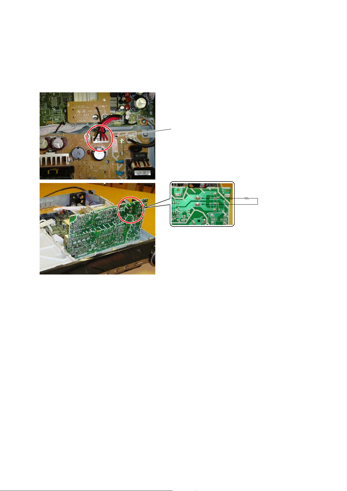
Discharge the charged electricity in capacitors to prevent electric shock as follows
When disassembling the machine, be sure to discharge the charged electricity in the following capacitors.
Use a resistor of 800 ohms, 2 Watts for discharging the following capacitors.
POWER board
C903: 390V
C932, C933, C934, CN904: 30V
Point of capacitor discharge for C932, C933, C934:
Connect to the red and black wire of CN904
800Ω/2W
Point of capacitor discharge for C903:
Connect to the foot of C903
11

HCD-DZ280/DZ680/HDZ284/HDZ485
SECTION 2
GENERAL
This section is extracted
from instruction manual.
Index to Parts and Control
(DZ280)
For more information, refer tothepagesindicated in parentheses.
Front panel
" / (on/standby)(21,78)
# ; (open/close) (27)
$ Front panel display (97)
% FUNCTION (23)
& (remote sensor) (10)
' MOVIE/MUSIC indicator (73)
( VOLUME co ntrol (27)
) REC TO USB (67)
* (USB) port (58)
+ OPERATION DIAL (27)
, PHONES jack(27)
- AUDIO IN jack(17)
. Play operation buttons (27)
/ Disc tray (27)
Additional Information
Rear panel
SPEAKER
SPEAKER
SUBWOOFER
CENTER
" SPEAKER jacks(15)
# COAXIAL 75Ω FM jack (19)
$ EURO AV 5 OUTPUT (TO TV) jack(16)
FRONTR FRONT L SUR R SUR L
HDMI OUT
DMPORT
DC5V
0.7A MAX
% DMPORT (DIGITAL MEDIAPORT) jack
(17, 69)
& HDMI OUT jack(16)
OUTPUT(TO TV)
COAXIAL 75
ANTENNA
FM
EUROAV
Front panel display
About the indications in the front panel display
" Playing status
# Flashes when the sleeptimer is set.
(74)
$ Displays the system’s statussuchas
chapter, title, or track number, time
information, radio frequency, playing
status, decoding mode, etc.
% Lights up when a station i s received .
(Radio only) (52)
& Stereo/Monaural eff ect (Radioonly)
(53)
' Lights up whentheHDMI OUT jack is
correctly connected to HDCP (Highbandwidth Digital Content Protection)
compliant device with HDMI or DVI
(Digital Visual Interface) input. (16)
( Current surround format(Exceptfor
JPEG image file)
) Lights up whenanNTSC disc is
loaded.
* Lights up when a Super Audio CD/CD
is loaded. (30)
GB
95
GB
96
Remote control
3)
XI (21,30, 32,45,
SNOITPIRCSEDNOTTUBREDROLACITEBAHPLA
Additional Information
ANGLE XT (28)
AUDIO RH (29)
CLEAR FT (32, 53)
D.TUNING RI (53)
DIMMER FE (75)
DISPLAY XB (54,64,75)
DVD MENU XH (35)
DVD TOP MENU RE (35)
DYNAMIC BASS (72)
ENTER XG (72)
FUNCTION +/– (23,27)
MEMORY SELECT
MENU XH (72)
MUTING (27)
NIGHT XE (72)
ONE-TOUCHPLAY FI (56)
1)
XT
Z–PO–A
PICTURE NAVI FG (38, 60)
PRESET +/– XK (53)
PROG +/–XK (72)
2)
S-AIR MODE
SLEEP RK (74)
SOUND MODE (73)
SUBTITLE RI (28)
SYSTEM MENU (20, 24,52,
THEATRE RL (55)
TOOLS XI (72)
TUNING +/– (52)
TV XM (72)
TV INPUT X (72)
VOLUME +/– (27)
FH
74)
Number buttons RG (31,52,72)
</ (on/standby) (20,21,27)
TV </ (on/standby) RM (72)
$/9/Y/D/ RT (20, 21, 30, 32,
52, 71)
+/– (37,57)
REPLAY/ADVANCE
(27)
/ XK (27)
N/. (27)
STEP / (27)
SLOW / (27)
)(play) F (27)
Y (stop) XL (27)
9 (pause) RB (27)
DISPLAY
71, 99)
0RETURNFB (31,72)
-/-- FT (72)
1)
See theincludedsupplement.
2)
This button is notavailable
for thismodel.
3)
This button is availablefor
the “DVD,”“USB,”or
“DMPORT” function.
Depending ontheDIGITAL
MEDIA PORTadapter, this
button may not work.
12
GB
97
GB
98

HCD-DZ280/DZ680/HDZ284/HDZ485
Index to Parts and Control
(DZ680)
For more information, r efertothepagesindicated in parentheses.
Front panel
" / (on/standby)(27,93)
# ; (open/close) (34)
$ Front panel display (114)
% FUNCTION (30)
& (remote sensor) (10)
' MOVIE/MUSIC indicator (88)
( VOLUME control(34)
) REC TO USB ( 74)
* (USB)port(65)
+ OPERATION DIAL (34)
, PHONES jack (34)
- AUDIO IN/A.CAL MIC jack (23,27,85)
. Play operation buttons (34)
/ Disc tray (34)
Rear panel
SPEAKER
FRONTR FRONT L SUR R SUR L
SPEAKER
SUBWOOFER
CENTER
" SPEAKER jacks (21)
# EZW-T100 slot (78)
$ COAXIAL 75Ω FM jack (25)
% EURO AV 5 OUTPUT (TO TV)jack(22)
& DMPORT (DIGITAL MEDIAPORT) jack
(23, 77)
TV
DIGITAL IN
HDMI OUT
COAXIALOPTICAL
Screws*
DMPORT
DC5V
0.7A MAX
EZW-T100
' HDMI OUT jack (22)
( TV (DIGITAL IN COAXIAL/OPTICAL)
jacks (22)
* CAUTION
Please do not remove th e screwsunless you
are installing the EZW-T100.
OUTPUT(TO TV)
COAXIAL 75
ANTENNA
FM
EUROAV
Additional Information
GB
112
Front panel display
About the indications in the front panel display
" Playing statu s
# Flashes when the sleeptimeris set.
(89)
$ Displays the system’sstatussuch as
chapter, title, or track number, time
information, radio frequency, playing
status, decoding mode, etc.
% Lights up wh en astation is received.
(Radio only) (59)
& Stereo/Monaural effect(Radio only)
(60)
' Lights up when the S-AIR transmitter
(not supplied) is insertedintheunit
and the system transmits the sound.
(78)
( Lights up whentheHDMIOUT jack is
correctly connected to HDCP (Highbandwidth Digital Content Protection)
compliant device with HDMI or DVI
(Digital Visual Interface) input. (22)
) Current surround format (Except for
JPEG image file)
* Lights up when an NTSC disc is
loaded.
+ Lights up when a Super Audio CD/CD
is loaded. (37)
Remote control
ANGLE XT (35)
AUDIO RH (36)
CLEAR FT (39, 60)
D.TUNING RI (60)
DIMMER FE (90)
DISPLAY XB (61,71,90)
DVD MENU XH (42)
DVD TOP MENURE (42)
DYNAMIC BASS (87)
ENTER XG (86)
FUNCTION +/– (30, 34)
MEMORY SELECT
MENU XH (86)
MUTING (34)
NIGHT XE (87)
ONE-TOUCH PLAY FI (63)
1)
XT
Z–PO–A
PICTURE NAVI FG (45, 67)
PRESET +/– XK (60)
PROG +/– XK (86)
S-AIR MODE FH
SLEEP RK (89)
SOUND MODE (88)
SUBTITLE RI (36)
SYSTEM MENU (26,31,59,
89)
THEATRE RL (62)
TOOLS XI (86)
TUNING +/– (59)
TV XM (86)
TV INPUT X (86)
VOLUME +/– (34)
Number buttons RG (38,59,86)
</ (on/standby) (26,27,34)
TV </ (on/standby) RM (86)
$/9/Y/D/ RT (26, 27, 37, 39,
59, 84)
+/– (44, 65)
REPLAY/ADVANCE
(34)
/ XK (34)
N/. (34)
STEP / (34)
SLOW / (34)
)(p
lay) F (34)
Y (stop) XL (34)
9 (pause) RB (34)
2)
DISPLAY
XI (27,37, 39,52,
84, 116)
0RETURNFB (38, 86)
-/-- FT (86)
1)
See theincludedsupplement.
2)
This button is availablefor
the “DVD,”“USB,”or
“DMPORT” function.
Depending ontheDIGITAL
MEDIA PORTadapter, this
button may not work.
GB
113
SNOITPIRCSEDNOTTUBREDROLACITEBAHPLA
Additional Information
114
GB
115
GB
13
HCD-DZ280/DZ680/HDZ284/HDZ485
Index to Parts and Control
(HDZ284)
For more information, r efertothepagesindicated in parentheses.
Front panel
" / (on/standby)(21,66)
# ; (open/close) (28)
$ Front panel display (84)
% FUNCTION (24)
& (remote sensor) (9)
' MOVIE/MUSIC indicator(62)
( VOLUME control(28)
) DMPORT BOOSTER (61)
* OPERATION DIAL (28)
+ PHONES jack (28)
, AUDIO IN/A.CAL MIC jack (17,21,59)
- Play operation buttons (28)
. Disc tray (28)
Rear panel
FRONTR FRONT L SUR R SUR L
SPEAKER
SUBWOOFER
CENTER
" SPEAKER jacks (14)
# COAXIAL 75Ω FM jack (19)
$ TV/VIDEO (AUDIO IN R/L)jacks (16)
% VIDEO OUT jack(15)
& COMPONENT VIDEO OUT jacks (15)
TV/VIDEO
DIGITAL IN
COAXIALOPTICAL
SPEAKER
HDMI OUT
DMPORT
DC5V
P
B/CBPR/CR
Y
0.7A MAX
' DMPORT ( D IGI TAL MEDIA PORT) jack
(17, 56)
( HDMI OUT jack (15)
) TV/VIDEO (DIGITAL IN COAXIAL/
OPTICAL) jacks (16)
ANTENNA
COAXIAL 75
FM
AUDIO IN
LR
VIDEO
OUT
TV/VIDEOCOMPONENTVIDEO OUT
Additional Information
US
82
Front panel display
About the indications in the front panel display
" Playing statu s
# Flashes when the sleeptimeris set.
(63)
$ Displays the system’sstatussuch as
chapter, title, or track number, time
information, radio frequency, playing
status, decoding mode, etc.
% Lights up when a station is received.
(Radio only) (51)
& Stereo/Monaural effect(Radio only)
(52)
' Lights up whentheHDMIOUT jack is
correctly connected to HDCP (Highbandwidth Digital Content Protection)
compliant device with HDMI or DVI
(Digital Visual Interface) input. (15)
( Current surround format (Except for
JPEG image file)
) Lights up when a Super Audio CD/CD
is loaded. (31)
Remote control
ANGLE (29)
AUDIO RI (30)
CLEAR FT (33, 52)
D.TUNING XT (52)
1)
DISC SKIP
FE
DISPLAY XB (53,64)
DVD MENU XH (35)
DVD TOP MENURE (35)
DYNAMIC BASS (61)
ENTER XG (60)
FUNCTION +/– (24, 28)
MENU XH (60)
MUTING (28)
NIGHT XE (61)
ONE-TOUCH PLAY FH (55)
Z–PO–A
PICTURE NAVI RH (38)
PRESET +/– XK (52)
1)
S-AIR MODE
SLEEP RK (63)
SOUND MODE (62)
SUBTITLE XT (29)
SYSTEM MENU XG (20,25,51,
THEATER RL (54)
TOOLS XI (60)
TUNING +/– (51)
TV XM (60)
TV CH +/–XK (60)
TV INPUT X (60)
TV VOL +/–FG (60)
VOLUME +/– (28)
63)
Number buttons RG (31,51,60)
</ (on/standby) (20,21,28)
TV </ (on/standby) RM (60)
$/9/Y/D/ RT (20, 21, 31, 33,
51, 58)
REPLAY/ADVANCE
(28)
/ XK (28)
N/. (28)
STEP / (28)
SLOW / (28)
)(play) F (28)
Y (stop) XL (28)
9 (pause) RB (28)
2)
DISPLAY
XI (21,31, 33,44,
58, 86)
0RETURNFB (31, 60)
FT (60)
1)
This button is notavailable
for thismodel.
2)
This button is availablefor
the “DVD” or“DMPORT”
function. Depending on the
DIGITAL MEDIA PORT
adapter,thisbutton maynot
work.
US
83
SNOITPIRCSEDNOTTUBREDROLACITEBAHPLA
Additional Information
84
14
US
US
85

HCD-DZ280/DZ680/HDZ284/HDZ485
Index to Parts and Control
(HDZ485)
For more information, r efertothepagesindicated in parentheses.
Front panel
" / (on/standby)(25,76)
# ; (open/close) (32)
$ Front panel display (96)
% FUNCTION (28)
& (remote sensor) (8)
' MOVIE/MUSIC indicator(72)
( VOLUME control(32)
) DMPORT BOOSTER (71)
* OPERATION DIAL (32)
+ PHONES jack (32)
, AUDIO IN/A.CAL MIC jack (21,25,69)
- Play operation buttons (32)
. Disc tray (32)
Rear panel
FRONTR FRONT L SUR R SUR L
SPEAKER
SUBWOOFER
CENTER
" SPEAKER jacks (18)
# EZW-T100 slot (62)
$ COAXIAL 75Ω FM jack (23)
% TV/VIDEO(AUDIO IN R/L) jacks (20)
& VIDEO OUT jack(19)
' COMPONENT VIDEO OUTjacks(19)
TV/VIDEO
DIGITAL IN
COAXIALOPTICAL
Screws*
SPEAKER
HDMI OUT
DMPORT
DC5V
P
B/CBPR/CR
Y
0.7A MAX
( DMPORT ( D IGI TAL MEDIA PORT) jack
(21, 61)
) HDMI OUT jack (19)
* TV/VIDEO (DIGITAL IN COAXIAL/
OPTICAL) jacks (20)
* CAUTION
Please do not remove th e screwsunless you
are installing the EZW-T100.
ANTENNA
COAXIAL 75
EZW-T100
VIDEO
OUT
FM
AUDIO IN
LR
TV/VIDEOCOMPONENTVIDEO OUT
Additional Information
GB
94
Front panel display
About the indications in the front panel display
" Playing statu s
# Flashes when the sleeptimeris set.
(73)
$ Displays the system’sstatussuch as
chapter, title, or track number, time
information, radio frequency, playing
status, decoding mode, etc.
% Lights up when a station is received.
(Radio only) (55)
& Stereo/Monaural effect(Radio only)
(56)
' Lights up when the S-AIR transmitter
(not supplied) is insertedintheunit
and the system transmits the sound.
(62)
( Lights up whentheHDMIOUT jack is
correctly connected to HDCP (Highbandwidth Digital Content Protection)
compliant device with HDMI or DVI
(Digital Visual Interface)input.(19)
) Current surround format(Except for
JPEG image file)
* Lights up when a Super Audio CD/CD
is loaded. (35)
Remote control
ANGLE (33)
AUDIO RI (34)
CLEAR FT (37, 56)
D.TUNING XT (56)
1)
DISC SKIP
FE
DISPLAY XB (57,74)
DVD MENU XH (39)
DVD TOP MENURE (39)
DYNAMIC BASS (71)
ENTER XG (70)
FUNCTION +/– (28, 32)
MENU XH (70)
MUTING (32)
NIGHT XE (71)
ONE-TOUCH PLAY FH (59)
Z–PO–A
PICTURE NAVI RH (42)
PRESET +/– XK (56)
S-AIR MODE
SLEEP RK (73)
SOUND MODE (72)
SUBTITLE XT (33)
SYSTEM MENU XG (24,29,55,
62, 73)
THEATER RL (58)
TOOLS XI (70)
TUNING +/– (55)
TV XM (70)
TV CH +/–XK (70)
TV INPUT X (70)
TV VOL +/–FG (70)
VOLUME +/– (32)
Number buttons RG (35,55,70)
</ (on/standby) (24,25,32)
TV </ (on/standby) RM (70)
$/9/Y/D/ RT (24, 25, 35, 37,
55,
68)
REPLAY/ADVA
(32)
/ XK (32)
N/. (32)
STEP / (32)
SLOW / (32)
)(play) F (32)
Y (stop) XL (32)
9 (pause) RB (32)
2)
DISPLAY
XI (25,35, 37,48,
68, 98)
0RETURNFB (35, 70)
FT (70)
1)
This button is notavailable
for thismodel.
2)
This button is availablefor
the “DVD” or“DMPORT”
function. Depending on the
DIGITAL MEDIA PORT
adapter,thisbutton maynot
work.
SNOITPIRCSEDNOTTUBREDROLACITEBAHPLA
NCE
GB
95
Additional Information
GB
96
GB
97
15

HCD-DZ280/DZ680/HDZ284/HDZ485
DISASSEMBLY
• This set can be disassembled in the order shown below.
SET
3-1. CASE
(Page 17)
3-2. FRONT PANEL SECTION
(Page 17)
SECTION 3
3-3. BACK PANEL SECTION
(DZ680/HDZ485)
(Page 18)
3-5. DVD MECHANISM DECK
(Page 19)
3-6. POWER BOARD,
USB BOARD (DZ280/DZ680)
(Page 19)
3-7. MAIN BOARD,
SPEAKER BOARD
(Page 20)
3-8. IO-SCART BOARD (DZ280/DZ680),
IO-COMPONENT BOARD (HDZ284/HDZ485)
(Page 20)
3-4. BACK PANEL SECTION
(DZ280/HDZ284)
(Page 18)
3-9. TRAY
(Page 21)
3-10. BELT
(Page 21)
3-11. MS-203 BOARD
(Page 22)
3-12. BASE UNIT
(Page 22)
3-13. OPTICAL PICK-UP
(Page 23)
16

Note: Follow the disassembly procedure in the numerical order given.
HCD-DZ280/DZ680/HDZ284/HDZ485
3-1. CASE
case
two screws
(case 3 TP2)
five screws
(BV/ring)
two screws
(case 3 TP2)
3-2. FRONT PANEL SECTION
wire (flat type)(17 core)
(CN506)
claw
loading panel
front panel section
CN4014 (4P)
claw
four screws
(+BV3 (3-CR))
CN3001 (3P)
label
tray
17

HCD-DZ280/DZ680/HDZ284/HDZ485
3-3. BACK PANEL SECTION (DZ680/HDZ485)
RE back panel section
two screws
(+BVTP 3 × 8)
wire (flat type) (11 core) (CN4017)
(DZ680)
wire (flat type) (9 core) (CN4016)
(HDZ485)
CN101 (4P)
three screws
(+BVTP 3 × 8)
CN102 (2P)
screw
(+BVTP 3 × 8)
screw
(+B 3 × 6)
RB two screws
(+BVTP 3 × 8)
RT screw
(+BVTP 3 × 8)
CN3000 (2P)
CN9010 (2P)
wire (flat type) (13 core)
(CN306)
3-4. BACK PANEL SECTION (DZ280/HDZ284)
back panel section
wire (flat type) (11 core) (CN4017)
(DZ280)
wire (flat type) (9 core) (CN4016)
(HDZ284)
two screws
(+BVTP 3 × 8)
three screws
(+BVTP 3 × 8)
screw
(+BVTP 3 × 8)
screw
(+B 3 × 6)
two screws
(+BV3 (3-CR))
screw
(+BVTP 3 × 8)
CN3000 (2P)
CN9010 (2P)
18

3-5. DVD MECHANISM DECK
HCD-DZ280/DZ680/HDZ284/HDZ485
screw
(+BV3 (3-CR))
two screws
(+BV3 (3-CR))
DVD mechanism deck
screw
(+BV3 (3-CR))
cover (CDM-DSY)
screw
(+BV3 (3-CR))
screw
(+BV3 (3-CR))
wire (flat type)(5 core)
(CN1202)
CN1201 (6P)
wire (flat type)(24 core)
(CN1101)
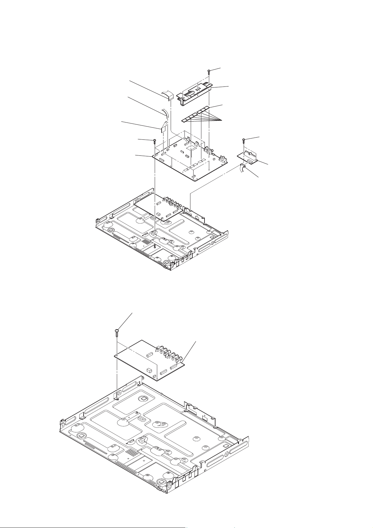
3-6. POWER BOARD, USB BOARD (DZ280/DZ680)
CN906 (13P)
RE three screws
(+PWH 3 × 8)
RI POWER board
two screws
(+BV3 (3-CR))
RG three screws
(+PWH 3 × 8)
CN904 (4P)
RB screw
(+BV3 (3-CR))
RT cover (rear)
screw
(+BV3 (3-CR))
cover (front)
plate (POW) insulated
two screws
(+BVTP 3 × 8)
bracket (POW-DSY)
RH holder PC board
CN5201 (5P)
USB board (DZ280/DZ680)
19
HCD-DZ280/DZ680/HDZ284/HDZ485
3-7. MAIN BOARD, SPEAKER BOARD
wire (flat type) (17 core) (CN472)
(HDZ284/HDZ485)
wire (flat type) (19 core) (CN473)
(DZ280/DZ680)
wire (flat type) (5 core)
(CN303)
wire (flat type) (17 core) (CN503)
(HDZ284/HDZ485)
wire (flat type) (19 core) (CN504)
(DZ280/DZ680)
RB eight screws
(+BV3 (3-CR))
RT MAIN board
three screws
(+BV3 (3-CR))
heat sink section
radiation (HDZ485)
six radiation sheets
two screws
(+BV3 (3-CR))
SPEAKER board
CN5301 (8P)
3-8. IO-SCART BOARD (DZ280/DZ680), IO-COMPONENT BOARD (HDZ284/HDZ485)
two screws
(+BV3 (3-CR))
IO-SCART board (DZ280/DZ680)
IO-COMPONENT board (HDZ284/HDZ485)
20

3-9. TRAY
Move the chuck cam
in the direction of the arrow.
HCD-DZ280/DZ680/HDZ284/HDZ485
bottom side
two claws
3-10. BELT
chuck cam
tray
belt
two claws
21
HCD-DZ280/DZ680/HDZ284/HDZ485
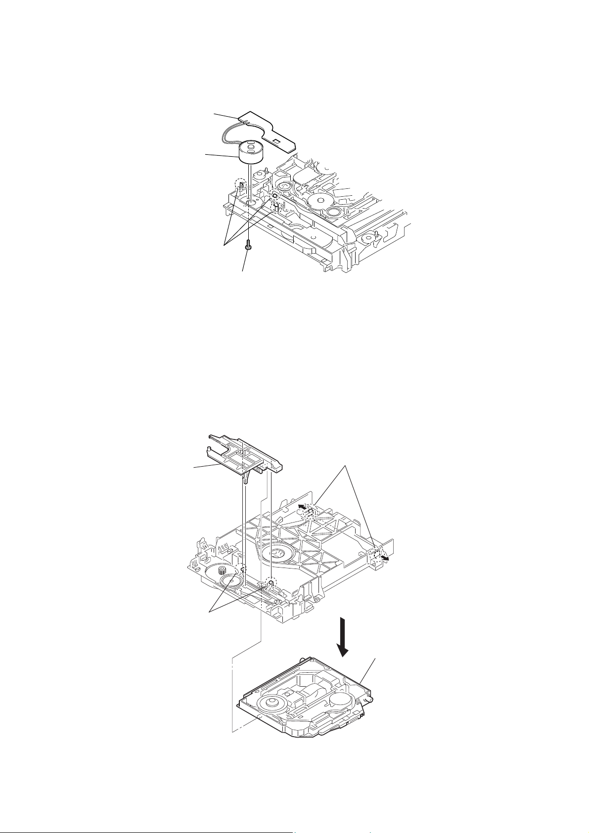
3-11. MS-203 BOARD
MS-203 board
DC motor
three claws
screw
(M 1.7 × 2.5)
3-12. BASE UNIT
chuck cam
two claws
two claws
base unit
22

3-13. OPTICAL PICK-UP
two insulator screws
FFC holder
two insulator screws
HCD-DZ280/DZ680/HDZ284/HDZ485
two insulators
optical pick-up
two insulators
(KHM-313CAA)
two claws
23

HCD-DZ280/DZ680/HDZ284/HDZ485
TEST MODE
SECTION 4
Note: Incorrect operations may be performed if the test mode is not
entered properly.
In this case, press the [?/1] button to turn the power off, and
retry to enter the test mode.
1. Cold Reset
• The cold reset clears all data including preset data stored
in the RAM to initial conditions. Execute this mode when
returning the set to the customers.
Procedure:
1. Press the [
2. Press three buttons [
] button to turn the power on.
?/1
], [N] and [
x
] simultaneously.
?/1
3. When this button is operated, display as “COLD RESET” for
a while and all of the settings are reset.
2. Panel Test Mode
• This mode is used to check the software version, FL and
KEY.
2-1. Display Test Mode
Procedure:
1. Press the [
2. Press three buttons [
] button to turn the power on.
?/1
], [.] and [FUNCTION] simultane-
x
ously.
3. When the display test mode is activated, all segments are turned
on. When the mode in, lamps of “MOVIE”, “MUSIC” and
“i-ENHANCER” are turn off.
4. To exit from this mode, press three buttons [x], [.] and
[FUNCTION] simultaneously.
2-2. Version Test Mode
Procedure:
1. When the display test mode is activated, press the [.] button
and the message “DSY2E” (DZ280), “DSY6E” (DZ680),
“DSY2N” (HDZ284), “DSY4N” (HDZ485) are displayed, the
version test mode is activated.
2. Whenever the [
] button is pressed, the display changes in
.
the following order.
“DSY4N” (Model name) U“NA*1” (Destination) UMC V ersion
*1: NA changes depending on destination.
3. Press the [>] button and the date of the software production
is displayed.
4. Press the [>] button again and the version is displayed.
5. To exit from this mode, press three buttons [x], [.] and
[FUNCTION] simultaneously.
2-4. Key Test Mode
Procedure:
1. When the display test mode is activated, press the [
] button,
N
to select the key test mode.
2. To enter the KEY test mode, the fl uorescent indicator displays
“K0 V0”. Each time an another button is pressed, “KEY” value
increases. However, once a button is pressed, it is no longer
taken into account. When all keys are pressed correctly, “K9
V0” is displayed.
3. When the [VOLUME] control is turned in the direction of (+),
“V0” is changed to “V1”, then ... “V9”.
When the [VOLUME] control is turned in the direction of (–),
“V0” is changed to “V9”, then ... “V1”.
4. To exit from this mode, press three buttons [
], [.] and
x
[FUNCTION] simultaneously.
3. Disc Tray Lock
• The disc tray lock function for the antitheft of an demonstra-
tion disc in the store is equipped.
Setting Procedure :
1. Press the [
] button to turn the set on.
?/1
2. Press the [FUNCTION] button to set DVD function.
3. Insert a disc.
4. Press the [x] button and the [Z] button simultaneously for fi ve
seconds.
5. The message “LOCKED” is displayed and the tray is locked.
Releasing Procedure :
1. Press the [x] button and the [Z] button simultaneously for fi ve
seconds again.
2. The message “UNLOCKED” is displayed and the tray is
unlocked.
Note: When “LOCKED” is displayed, the tray lock is not released by
turning power on/off with the [?/1] button.
4. DVD Ship Mode
• Use this mode when returning the set to the customer after
repair.
Procedure:
1. Press the [
] button to turn the set on.
?/1
2. Press the [FUNCTION] button to set the function “DVD”.
3. Remove all discs, and then press two buttons [N] and [
?/1
simultaneously.
4. After a message “MECHA LOCK” h “UNPLUG” is displayed on the fl uorescent indicator tube, pull out the AC plug.
5. To exit from this mode, press the [
] button to turn the set
?/1
on.
]
2-3. FL Pattern Test Mode
Procedure:
1. When the display test mode is activated, press the [x] button,
to select the FL pattern test mode. When the FL pattern test
mode, half segments of FL display and lamps of “MOVIE”,
“i-ENHANCER” are turn on.
2. Press the [x] button, half segments of FL display and lamp of
“MUSIC” is turn on.
3. Next press the [x] button, all segments of FL display is turn
on.
4. To exit from this mode, press three buttons [x], [.] and
[FUNCTION] simultaneously.
24

HCD-DZ280/DZ680/HDZ284/HDZ485
5. Product Out
• This mode moves the optical pick-up to the position durable
to vibration and clears all data including preset data stored in
the RAM to initial conditions. Use this mode when returning
the set to the customer after repair.
Procedure:
1. Press the [
] button to turn the power on.
?/1
2. Press the [FUNCTION] button to set the function “DVD”.
3. Remove all discs, and then press three buttons [x], [Z] and
[VOLUME+] simultaneously.
4. Displayed to message “initialize all data ...” on the fluorescent
indicator tube when pressing in turn the [4] t [DVD MENU]
t [CLEAR] buttons.
5. After the “STANDBY” blinking display fi nishes, the message
“MECHA LOCK” h “UNPLUG” is displayed on the
fl uorescent indicator tube disconnect the AC power plug, then
the product out mode is set.
DVD SECTION
6-1. GENERAL DESCRIPTION
• The IOP measurement allows you to make diagnosis and adjustment simply by using the remote commander and monitor TV. The instructions, diagnosis results, etc. are given on
the on-screen display (OSD).
Be sure to execute the IOP measurement when a BU (Base
Unit) is replaced.
6-2. HOW TO ENTER TEST MODE
While pressing the [
[VOLUME] control in the direction of (+) with the DVD player
in power on.
The Test Mode starts, displayed “SERVICE IN” on this model
display then the menu shown below will be displayed on the TV
screen.
* The display of the “Model Name” of the “Remocon Diagnosis
Menu” change with the model and the destination. Refer to
below on the model name.
DZ280 : DSY2E
DZ680 : DSY6E
HDZ284 : DSY2N
HDZ485 : DSY4N
0. External Chip Check
1. Servo Parameter Check
2. Drive Manual Operation
3. Emergency History
4. Version Information
] and [Z] buttons simultaneously, turn
x
Remocon Diagnosis Menu
1
Model Name
IF-con : Ver. XX.XX (XXXX)
Syscon : Ver. X.XXX
*1: Changes depending on destination
: DSY2N_XX
*
The menu above is the Remocon Diagnosis Menu screen which
consists of fi ve main functions. At the bottom of the menu screen,
the model name and IF-con version. To exit from the Test Mode,
press the [
] button on the remote commander.
?/1
6-3. EXECUTING IOP MEASUREMENT
In order to execute IOP measurement, the following standard procedures must be followed.
(1) In power on, while pressing the [
] and [Z] buttons simultane-
x
ously, turn the [VOLUME] control in the direction of (+).
Remocon Diagnosis Menu
0. External Chip Check
1. Servo Parameter Check
2. Drive Manual Operation
3. Emergency History
4. Version Information
1
Model Name
IF-con
Syscon : Ver. X.XXX
*1: Changes depending on destination
: DSY2N_XX
: Ver. XX.XX (XXXX)
*
25

HCD-DZ280/DZ680/HDZ284/HDZ485
(2) Select “2. Drive Manual Operation” by pressing the [2] button
on the remote commander. The screen will appear as shown.
Drive Manual Operation
1. Servo Control
2. Track/Layer Jump
3. Manual Adjustment
4. Tray Aging Mode
5. MIRR time adjust
0. Return to Top Menu
(3) Select “3. Manual Adjustment” by pressing the [3] button on
the remote commander. The screen will appear as shown.
Manual Adjust
1. Track Balance Adjust:
2. Track Gain Adjust:
3. Focus Balance Adjust:
4. Focus Gain Adjust:
5. Eq Boost Adjust:
6. Iop:
7. TRV. Level:
8. S curve(FE) Level:
9. RFL(PI) Level:
0. MIRR Time:
0P Change Value
[RETURN] Return to previous menu
(4) Select “6. IOP” by pressing the [6] button on the remote
commander.
6-4. EMERGENCY HISTORY
To check the emergency history, please follow the following
procedure.
(1) From the Top Menu of Remocon Diagnosis Menu, select “3.
Emergency History Check” by pressing the [3] button on the
remote commander. The following screen appears on the onscreen display.
Emg. History Check
Laser Hours CD 999h 59min
01. 01 05 04 04
00 00 00 00 00 00 23 45
02. 02 02 01 01 00 A9 4B 00
00 00 00 00 00 00 23 45
[Next] Next Page [Prev] Prev Page
[O] Return to Top Menu
DVD 999h 59min
00 92 46 00
(2) You can check the total time when the laser is turned on during
playback of DVD and CD from the above menu. The maximum
time, which can be displayed are 999h 59min.
(3) You can check the error code of latest 10 emergency history
from the above menu. To view the previous or next page of
emergency history, press [.] or [>] button on the remote
commander. The error code consists of the following three
blocks. The fi rst block indicates the error code. The second
block indicates the parameter and the third block indicates the
time of error code as shown below.
• Error Code
(5) Wait until a hexadecimal number appear.
Manual Adjust
1. Track Balance Adjust:
2. Track Gain Adjust:
3. Focus Balance Adjust:
4. Focus Gain Adjust:
5. Eq Boost Adjust:
6. Iop. 4F:
7. TRV. Level:
8. S curve(FE) Level:
9. RFL(PI) Level:
0. MIRR Time:
0P Change Value
[RETURN] Return to previous menu
(6) Convert each data from hexadecimal to decimal using
conversion table.
(7) Please fi nd the label on the rear of the BU (Base Unit).
The default IOP value is written in the label.
(8) Subtract between these two values.
(9) If the remainder is smaller than 93 (decimal), then it is OK.
However if the value is higher than 93, then the BU is defective
and need to be change.
(10) Press the [RETURN] button on the remote commander to
return back to previous menu.
(11) Press the [0] button on the remote commander to return to T op
Menu.
Emg. History Check
Laser Hours CD 999h 59min
*1 *2
01. 01 05 04 04
00 00 00 00 00 00 23 45
02. 02 02 01 01 00 A9 4B 00
00 00 00 00 00 00 23 45
[Next] Next Page [Prev] Prev Page
[O] Return to Top Menu
DVD 999h 59min
00 92 46 00
*3
*1 : Error Code
*2 : Parameter of error code
*3 : Time of error code
The meaning of error code is as below:
01: Communication error (No reply from syscon)
02: Syscon hung up
03: Power OFF request when syscon hung up
19: Thermal shutdown
24: MoveSledHome error
25: Mechanical move error (5 Changer)
26: Mechanical move stack error
30: DC motor adjustment error
31: DPD offset adjustment error
32: TE balance adjustment error
33: TE sensor adjustment error
34: TE loop gain adjustment error
35: FE loop gain adjustment error
36: Bad jitter after adjustment
40: Focus NG
42: Focus layer jump NG
52: Open kick spindle error
51: Spindle stop error
26
HCD-DZ280/DZ680/HDZ284/HDZ485
60: Focus on error
61: Seek fail error
62: Read Q data/ID error
70: Lead in data read fail
71: TOC read time out (CD)
80: Can’t buffering
81: Unknown media type
6-4-1. Clear the Laser Hour
Press [
DISPLAY] button and then press [CLEAR] button on
the remote commander. The data for both CD and DVD data are
reset.
Emg. History Check
Laser Hours CD 0h 0min
01. 01 05 04 04
00 00 00 00 00 00 23 45
02. 02 02 01 01 00 A9 4B 00
00 00 00 00 00 00 23 45
[Next] Next Page [Prev] Prev Page
[O] Return to Top Menu
DVD 0h 0min
00 92 46 00
6-4-2. Clear the Emergency History
Press [DVD TOP MENU] button and then press [CLEAR] button
on the remote commander. The error code for all emer gency history
would be reset.
Emg. History Check
Laser Hours CD 999h 59min
01. 00 00 00 00
00 00 00 00 00 00 00 00
02. 00 00 00 00 00 00 00 00
00 00 00 00 00 00 00 00
[Next] Next Page [Prev] Prev Page
[O] Return to Top Menu
DVD 999h 59min
00 00 00 00
6-4-3. Clear the Initialize Setup Data
Press [DVD MENU] button and then press [CLEAR] button on the
remote commander.
6-4-4. Return to the Top Menu of Remocon Diagnosis
Menu
Press [0] button on the remote commander.
6-5. CHECK VERSION INFORMATION
To check the version information, please follow the following
procedure.
(1) From the Top Menu of Remocon Diagnosis Menu, select “4.
Version Information” by pressing the [4] button on the remote
commander. The following screen appears on the on-screen
display.
Version information
Firm (Main) : Ver. xxxxx
Firm (Sub) : xxxxx
RISC : xxxxx
8032 : xxxxx
Audio DSP : xxxxx
Servo DSP : xxxxx
Phy,Adr, : F,F,F,F,
[O] Return to Top Menu
To return to the Top Menu of Remocon Diagnosis Menu, press
[0] button on the remote commander.
7. D.C.A.C. (AUTOMATIC ACOUSTIC FIELD CALIBRATION) TEST MODE (DZ680/HDZ284/HDZ485)
Procedure:
1. Press the [
] button to turn the power on.
?/1
2. Press the [FUNCTION] button to set the function “ DVD”.
3. Insert Calibration mic (ECM-AC2) supplied as an accessory
into the AUDIO IN/A.CAL MIC jack.
4. While pressing the [x] and [Z] buttons simultaneously, turn
the [VOLUME] control in the direction of (–).
5. Confi rm that the following are shown on the display panel.
1 The JACK inserted/non-inserted detection display and the
STEREO/MONO detection display.
2 Presence of DIGITAL voice input to the microcomputer.
(OK: input, NG: no input)
3 The AD value of the MIC input to the microcomputer.
(shown “255h”)
Emg. History Check
Laser Hours CD 999h 59min
DVD 999h 59min
initialize setup data...
[Next] Next Page [Prev] Prev Page
[O] Return to Top Menu
“NON” : Not detected
“ST” : STEREO
“MN” : MONO
OK : input
NG : no input
0-255 (Changes in real time)
6. To exit from this mode, press the [x] and [Z] buttons simultaneously, turn the [VOLUME] control in the direction of (–).
27

HCD-DZ280/DZ680/HDZ284/HDZ485
8. AMP TEST MODE
• This mode is used to measurement and test of the AMP connection.
Procedure:
1. Press the [
] button to turn the power on.
?/1
2. Press three buttons [x], [N] and [Z] simultaneously. When
the this mode, blink to segments (“SA-CD” and “CAT”) on FL
display.
3. Press [DISPLAY] button of the remote commander. When the
this mode is displayed as “MEASURE” on FL display.
Whenever the [DISPLAY] button is pressed, the AMP test
mode changes in the following order.
MEASUREUSAFETY
MEASURE: AMP measurement mode
SAFETY: AMP regulations, temperature, character mode
4. Press [MUTING] button on the remote commander. When the
this mode is displayed as “VOL N” on FL display.
Whenever the [MUTING] button is pressed, the VOL test
mode changes in the following order.
VOL N UVOL M/M
VOL N: Turn the [VOLUME] control, the display is
change in succession (MIN y MAX)
VOL M/M: Turn the [VOLUME] control in the direction of
(+) is change to “MIN”, turn the direction of (–)
is change to “MAX”.
5. To exit from this mode, press the [
] button to “COLD
?/1
RESET” and turn the power off.
9. DEMO PLAY MODE OUT
It is a mode to release the demonstration reproduct by the dedicated
demonstration disc.
1. During playback the DEMO Disc, press the [x] and [N]
buttons for fi ve seconds simultaneously.
2. The message “DEMO OFF” is displayed, a mode to reproduct
the demonstration is released.
10. DMPORT (DIGITAL MEDIA PORT) TEST
1. Connect the DMPORT CHECK JIG (P/N: J-2501-309-A) with
the terminal DMPORT.
2. Press the [
] button to turn the power on.
?/1
3. Confi rm that both LEDs of the DMPORT confi rmation JIG
lights. (Confi rmation the power supply line.)
4. Set the [FUNCTION] button with “DMPORT” on this model.
5. Press three buttons [x], [N] and [FUNCTION] simultaneously, the DMPORT test mode is activated.
6. It is confi rmed that “DMPORT OK” is displayed on this set
display. (Confi rmation of communication line)
7. To a pin jack of the DMPORT confi rmation JIG input informa-
tion relevant to audio signal (sine-wave 1.0Vrms) and composite video signal (white 100% 1.0Vp-p, color bar, etc.)
8. Confi rm the output of speakers and monitor TV. (Confi rmation
of analog signal)
9. To exit from this mode, press three buttons [x], [N] and
[FUNCTION] simultaneously.
CN4000 (DZ280/DZ680),
J4001 (HDZ284/HDZ485)
SET
IO-SCART or
IO-COMPONENT
board
SPEAKER
board
TV
FL speaker,
FR speaker
TB5301
VIDEO
AUDIO
color pattern
generator
AF oscillator
DMPORT
CHECK JIG
(P/N: J-2501-309-A)
J001 7
CN451
MAIN
board
28

11. PROTECTION FACTOR (SD DETECTION/
DC DETECTION) IDENTIFICATION TEST MODE
When an error is detected, the FL tube alternately displays
“PROTECTOR h PUSH POWER”.
r Press the [
* Buttons other than the [
“STANDBY” blinks three times on the FL tube.
r
The protection release state (POWER OFF) is established.
(No FL tube display)
r Press the [
The power to the system turns on, and the normal operation is
established. (Restore)
During the protection state:
1. If the AC plug is connected or disconnected during the
protection state, the protection state is released, and the
normal operation is established. (The protection state is not
maintained.)
2. The protection factor is displayed by pressing the [RETURN]
t [3] t [2] t [0] t [0] t [ANGLE] buttons of the
remote commander.
(during the “PROTECTOR h PUSH POWER” display).
k When SD is detected: Repeats
“SD DETECT h PROTECTOR”.
k When DC is detected: Repeats
“DC DETECT h PROTECTOR”.
] button.
?/1
] button two times.
?/1
] button are invalid.
?/1
HCD-DZ280/DZ680/HDZ284/HDZ485
PL: SD detection
When the “L” output from the SD (shutdown) port on the
S-MASTER POWER Driver Shutdown and voltage descent
(15V or less) of 30V power supply (PVDD) are detected.
DC detection
When the “L” output from the power/speaker error detection
circuit (DC detection port) is detected for two seconds
continually, the power system other than that of the FL tube
is turned off, and the protection state is established.
29

HCD-DZ280/DZ680/HDZ284/HDZ485
SECTION 5
ELECTRICAL ADJUSTMENTS
DVD SECTION
When the optical pick-up assy is replaced, perform the
“EXECUTING IOP MEASUREMENT”.
EXECUTING IOP MEASUREMENT (See page 25)
TUNER SECTION
[FM Tune Level Check]
generator
SET
Procedure:
1. Turn the power on.
2. Input the following signal from Signal Generator to FM
antenna input directly.
* Carrier Freq : A = 87.5 MHz, B = 98 MHz, C = 108 MHz
Deviation : 75 kHz
Modulation : 1 kHz
ANT input : 35 dBu (EMF)
Note: Please use 75 ohm “coaxial cable” to connect SG and the set. You
cannot use video cable for checking.
Please use SG whose output impedance is 75 ohm.
3. Set to FM tuner function and tune A, B and C signals.
4. Confi rm “TUNED” is lit on the display for A, B and C
signals.
FM ANTENNA
OUT (75 Ω)
The mark of “TUNED” means “The selected station signal is
received in good condition.”
30
 Loading...