

HCD-GX250
Amplifier section
AUDIO POWER SPECIFICATIONS
POWER OUTPUT AND TOTAL HARMONIC
DISTORTION:
With 6 ohm loads, both channels driven, from
120 – 10,000 Hz: rat ed 140 watts per channel
minimum RMS power, with no more than 10%
total harmonic distortion from 250 milliwatts to
rated output.
Continuous RMS power output (reference):
140 + 140 watts (6 ohms at
1 kHz, 10% THD)
Total harmonic distortion less than 0.07% (6 ohms at
1kHz, 70 W)
CD player section
System Compact disc and dig ital
audio system
Laser Semiconductor laser
(λ=780 nm)
Emission duration:
continuous
Frequency response 2 Hz – 20 kHz (±0.5 dB)
Wavelength 780 – 790 nm
Signal-to-noise ratio More than 90 dB
Dynamic range More than 90 dB
Tape deck section
Recording system 4-track 2-channel, stereo
Frequency response 50 – 13,000 Hz (±3 dB),
using Sony TYPE I
cassettes
Tuner section
FM stereo, FM/AM super he te rodyne tuner
FM tuner section
Tuning range 87.5 – 108.0 MHz
(100-kHz step)
Antenna FM lead antenna
Antenna terminals 75 ohms unbalanced
Intermediate frequency 10.7 MHz
AM tuner section
Tuning range 530 – 1,710 kHz
(with the tuning interv al
set at 10 kHz)
531 – 1,710 kHz
(with the tuning interv al
set at 9 kHz)
Antenna AM loop antenna
Antenna terminals External antenna terminal
Intermediate frequency 450 kHz
General
Power requirements 120 V AC, 60 Hz
Power consumption
USA models: 205 watts
Canadian models: 260 VA
Dimensions (w/h/d) incl. projecting parts and
controls Amplifier/Tune r/ Tape/CD section:
Approx. 280 × 327 ×
425 mm
ss Ma Approx. 10.0 kg
Design and specifications are subject to change
without notice.
SERVICE MANUAL
Ver 1.0 2004.03
• HCD-GX250 is the tuner, deck, CD and
amplifier section in MHC-GX250.
CD
Section
Tape deck Model Name Using Similar Mechanism New
Section T ape Transport Mechanism T ype CWM43FF-05
US Model
Canadian Model
Model Name Using Similar Mechanism New
CD Mechanism Type CDM74-K6BD80
Optical Pick-up Name
KSM-213DCP/Z-NP
9-877-537-01
2004C1678-1
© 2004.03
Sony Corporation
Home Audio Company
Published by Sony Engineering Corporation
SPECIFICATIONS
MINI HI-FI COMPONENT SYSTEM
HCD-GX250
SAFETY CHECK-OUT
After correcting the original service problem, perform the
following safety checks before releasing the set to the customer:
Check the antenna terminals, metal trim, “metallized” knobs, screws,
and all other exposed metal parts for AC leakage. Check leakage as
described below.
LEAKAGE
The AC leakage from any exposed metal part to earth ground
and from all exposed metal parts to any exposed metal part having
a return to chassis, must not exceed 0.5 mA (500 microamperes).
Leakage current can be measured by any one of three methods.
1. A commercial leakage tester, such as the Simpson 229 or RCA
WT -540A. Follo w the manufacturers’ instructions to use these
instruments.
2. A battery-operated AC milliammeter. The Data Precision 245
digital multimeter is suitable for this job.
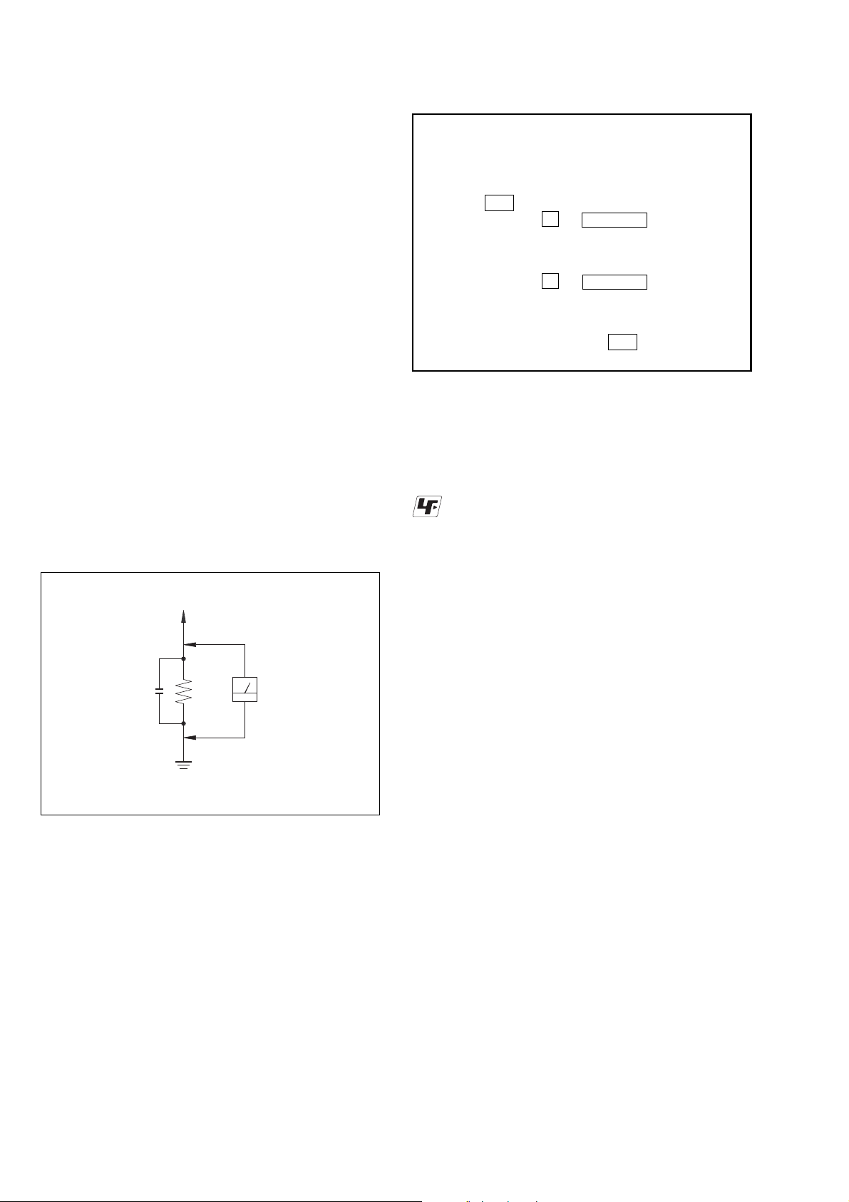
3. Measuring the voltage drop across a resistor by means of a
VOM or battery-operated AC v oltmeter. The “limit” indication
is 0.75 V, so analog meters must have an accurate low-voltage
scale. The Simpson 250 and Sanwa SH-63Trd are e xamples of
a passive VOM that is suitable. Nearly all battery operated
digital multimeters that have a 2V AC range are suitable. (See
Fig. A)
To Exposed Metal
Parts on Set
AC
0.15 µF
1.5 kΩ
Earth Ground
Voltmeter
(0.75 V)
The release method of a CD disc tray LOCK function
There is a disc lock function for the disc theft prevention for a
demonstration at a shop front in this machine.
Procedue:
1. Press the ?/1 button to turn the set on.
2. Press two buttons of x and Z (EJECT) simultaneously for
five seconds.
3. The message “LOCKED” is displayed and the tray is locked.
(Even if exiting from this mode, the tray is still locked.)
4. Press two buttons of x and Z (EJECT) simultaneously for
five seconds again.
5. The message “UNLOCKED” is displayed and the tray is
unlocked.
6. To exit from this mode, press the ?/1 button to turn the set
off.
Unleaded solder
Boards requiring use of unleaded solder are printed with the leadfree mark (LF) indicating the solder contains no lead.
(Caution: Some printed circuit boards may not come printed with
the lead free mark due to their particular size.)
: LEAD FREE MARK
Unleaded solder has the following characteristics.
• Unleaded solder melts at a temperature about 40°C higher than
ordinary solder.
Ordinary soldering irons can be used but the iron tip has to be
applied to the solder joint for a slightly longer time.
Soldering irons using a temperature regulator should be set to
about 350°C.
Caution: The printed pattern (copper foil) may peel away if the
heated tip is applied for too long, so be careful!
• Strong viscosity
Unleaded solder is more viscous (sticky , less prone to flow) than
ordinary solder so use caution not to let solder bridges occur such
as on IC pins, etc.
• Usable with ordinary solder
It is best to use only unleaded solder but unleaded solder may
also be added to ordinary solder.
Fig. A. Using an A C v oltmeter to check A C leakage.
SAFETY-RELATED COMPONENT WARNING!!
COMPONENTS IDENTIFIED BY MARK 0 OR DOTTED LINE WITH
MARK 0 ON THE SCHEMATIC DIAGRAMS AND IN THE PARTS
LIST ARE CRITICAL TO SAFE OPERATION. REPLACE THESE
COMPONENTS WITH SONY PARTS WHOSE PART NUMBERS
APPEAR AS SHOWN IN THIS MANUAL OR IN SUPPLEMENTS
PUBLISHED BY SONY .
ATTENTION AU COMPOSANT AYANT RAPPORT
LES COMPOSANTS IDENTIFÉS P AR UNE MARQUE 0 SUR LES
DIAGRAMMES SCHÉMA TIQUES ET LA LISTE DES PIÈCES SONT
CRITIQUES POUR LA SÉCURITÉ DE FONCTIONNEMENT. NE
REMPLACER CES COMPOSANTS QUE PAR DES PIÈSES SONY
DONT LES NUMÉROS SONT DONNÉS DANS CE MANUEL OU
DANS LES SUPPÉMENTS PUBLIÉS PAR SONY.
À LA SÉCURITÉ!
2
HCD-GX250
NOTES ON HANDLING THE OPTICAL PICK-UP
BLOCK OR BASE UNIT
The laser diode in the optical pick-up block may suffer electrostatic
break-down because of the potential difference generated by the
charged electrostatic load, etc. on clothing and the human body.
During repair, pay attention to electrostatic break-down and also
use the procedure in the printed matter which is included in the
repair parts.
The flexible board is easily damaged and should be handled with
care.
NOTES ON LASER DIODE EMISSION CHECK
The laser beam on this model is concentrated so as to be focused on
the disc reflective surface by the objective lens in the optical pickup block. Therefore, when checking the laser diode emission,
observe from more than 30 cm away from the objective lens.
Laser component in this product is capable
of emitting radiation exceeding the limit for
Class 1.
TABLE OF CONTENTS
1. SERVICING NOTE··························································4
2. GENERAL ·········································································· 6
3. DISASSEMBLY
3-1. Cover (Top) ·····································································9
3-2. CD Door·········································································· 9
3-3. Front Panel Section ······················································· 10
3-4. CD Mechanism Deck (CDM74-K6BD80) ··················· 10
3-5. Tape Mechanism Deck, GAME JACK Board··············· 11
3-6. PANEL Board ······························································· 11
3-7. BACK PANEL Section, SUB-TRANS Board ·············· 12
3-8. Power Transformer······················································· 12
3-9. MAIN Board ································································· 13
3-10. AMP Board ································································· 13
3-11. BD80A Board ····························································· 14
3-12. CONNECT Board······················································· 14
3-13. DRIVER Board, SW Board ········································ 15
3-14. Optical Pick-up (KSM-213DCP/Z-NP)······················ 15
3-15. SENSOR Board ·························································· 16
3-16. MOTOR (TB) Board··················································· 16
3-17. MOTOR (LD) Board ·················································· 17
4. TEST MODE ···································································· 18
This appliance is classified as a CLASS 1 LASER product. The
CLASS 1 LASER PRODUCT MARKING is located on the rear
exterior.
CAUTION
Use of controls or adjustments or performance of procedures
other than those specified herein may result in hazardous radiation
exposure.
Notes on chip component replacement
•Never reuse a disconnected chip component.
• Notice that the minus side of a tantalum capacitor may be
damaged by heat.
Flexible Circuit Board Repairing
•Keep the temperature of soldering iron around 270˚C
during repairing.
• Do not touch the soldering iron on the same conductor of the
circuit board (within 3 times).
• Be careful not to apply force on the conductor when soldering
or unsoldering.
5. DIAGRAMS
5-1. Block Diagrams – PANEL Section – ···························· 22
– MAIN Section – ······················································· 23
– BD/DRIVER Section – ············································ 24
5-2. Printed Wiring Board – BD80A Section –···················· 25
5-3. Schematic Diagram – BD80A Section – ······················ 26
5-4. Printed Wiring Board – CD MECHANISM Section –· 27
5-5. Schematic Diagram – CD MECHANISM Section –···· 28
5-6. Printed Wiring Board – MAIN Section – ····················· 29
5-7. Schematic Diagram – MAIN Section (1/2) – ··············· 30
5-8. Schematic Diagram – MAIN Section (2/2) – ··············· 31
5-9. Printed Wiring Board – PANEL COMB Section – ······· 32
5-10. Schematic Diagram – PANEL COMB Section – ······· 33
5-11. Printed Wiring Board – PANEL Section –·················· 34
5-12. Schematic Diagram – PANEL Section (1/2) – ··········· 35
5-13. Schematic Diagram – PANEL Section (2/2) – ··········· 36
5-14. Printed Wiring Board – TRANS Section – ················· 37
5-15. Printed Wiring Board – AMP Section – ······················ 38
5-16. Schematic Diagram – AMP POWER Section – ········· 39
5-17. IC Pin Function Description ······································· 41
6. EXPLODED VIEWS
6-1. MAIN Section······························································· 46
6-2. Front Panel Section ······················································· 47
6-3. MAIN Board Section ···················································· 48
6-4. CD Mechanism Deck Section -1 (CDM74-K6BD80) ·· 49
6-4. CD Mechanism Deck Section -2 (CDM74-K6BD80) ·· 50
7. ELECTRICAL PARTS LIST ······································· 51
3
HCD-GX250
d
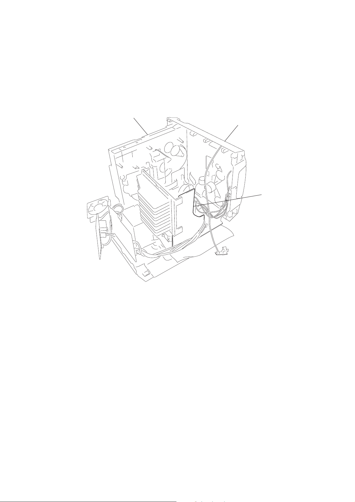
• SERVICE POSITION -1 (AMP BOARD)
To inspect the AMP board, turn both of the front panel
and the CD mechanism deck so that the left side of the product faces down.
CD mechanism deck
SECTION 1
SERVICING NOTE
front panel
AMP boar
4
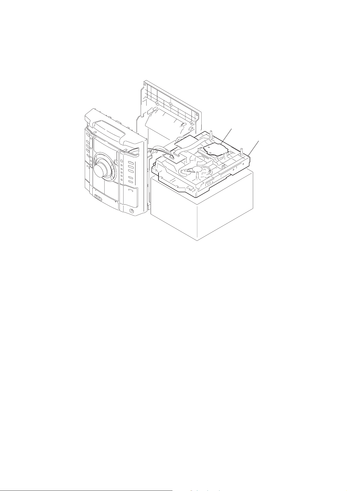
• SERVICE POSITION -2 (BD80A BOARD)
k
Remove the CD mechanism deck and place it on top of the pedestal as shown.
Inspect the BD80A bard in this set up.
HCD-GX250
BD80A board
CD mechanism dec
5
HCD-GX250
Illustrati
SECTION 2
GENERAL
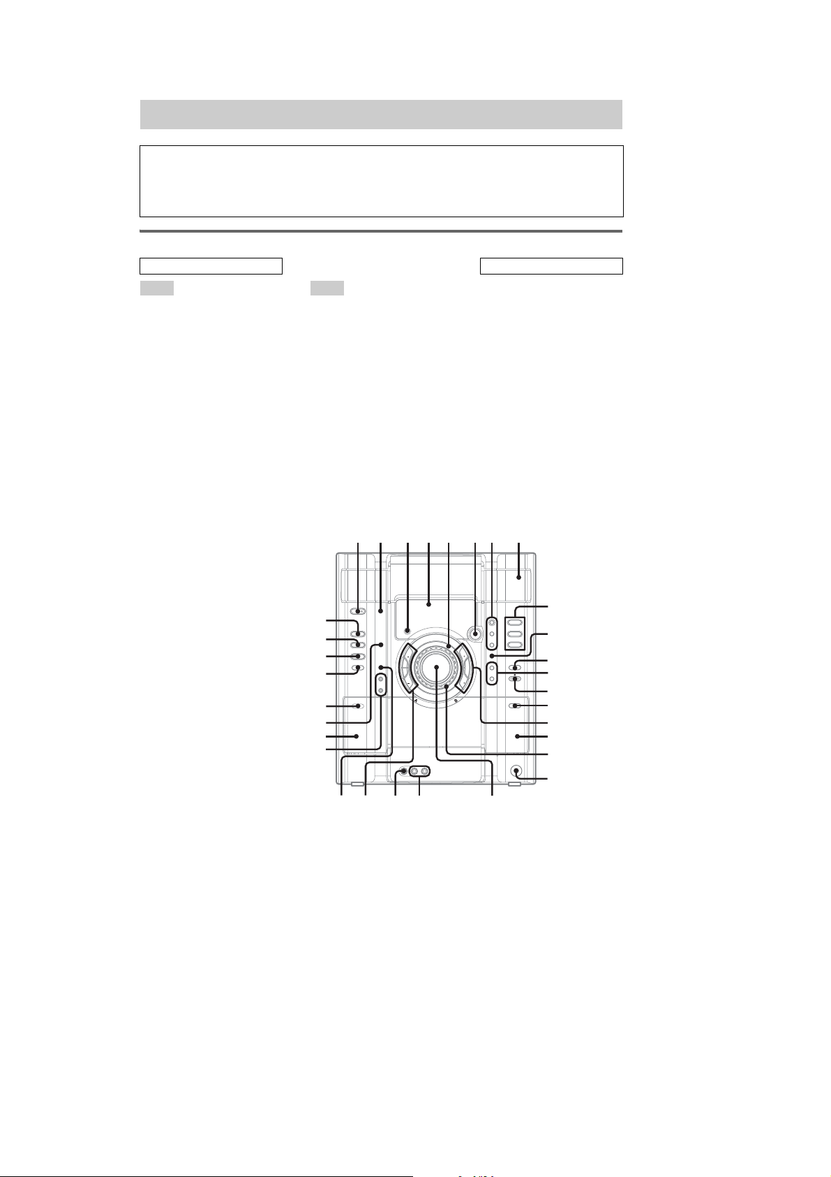
List of button locations and reference pages
How to use this page
Use this page to find the loca tio n of buttons and other
parts of the system that are mentioned in the text.
Main unit
ALPHABETICAL ORDER
A – O P – Z
CD eg (9, 11, 14, 19, 20)
CD SYNC wj (19)
Deck A wk (18)
Deck B qj (18, 19, 20, 24)
DISC 1 – 3 q; (12, 14, 35)
DISC SKIP/EX-CHANGE qs
(11, 12, 14, 19)
Disc tray 9 (11)
DISPLAY 2 (17, 27, 28)
Display window 5
EFFECT ON/OFF 8 (22)
ENTER qa (14, 15 , 22)
EQ BAND 7 (22)
GAME es (20, 23, 30)
GAME INPUT AUDIO L/R jacks
wd (20, 29)
GAME INPUT VIDEO jack wf
(29)
GAME MIXING wh (23)
GROOVE 8 (21)
Operation Dial
(– EQ +/l L) 6 (12,
14, 19, 22)
P FILE qd (22)
PHONES jack ql
PLAY MODE wl (12, 14, 18, 19,
20, 35)
PRESET EQ qd (22)
REC PAUSE/START wj (19, 20,
23, 24)
Remote sensor 4
SURROUND 8 (23)
TAPE A/B ed (18, 19, 20, 24)
TUNER/BAND ef (15, 16, 20)
TUNING MODE wl (15, 16, 35)
TUNING + qh (15, 16)
TUNING – wg (15, 16)
VOLUME control w; (21)
12 45 6 78 9
eg
ef
ed
es
e;
wl
wk
wj
on number
r
TAPE A/B ed (18, 19, 20, 24)
Name of button/pa rt Reference page
RR
BUTTON DESCRIPTIONS
?/1 (power) 1 (8, 16, 27, 30, 33,
35)
X (pause) wg (12, 19)
Z (eject) qf (11)
PUSH Z (deck B) (eject) qg (18)
x (stop) wg (12, 19, 24, 35)
M (fast forward) qh (12, 19)
H (play) qh (12, 18, 19)
m (rewind) wg (12, 19)
Z PUSH (deck A) (eject) e; (18)
q;
qa
j
ALBUM
S
s
TUNING TUNING
J
ALBUM
H
h
qs
qd
qf
qg
qh
qj
qk
ql
6
wh
wd
wfwg
w;
HCD-GX250
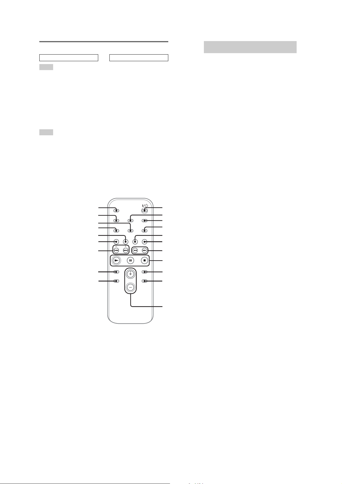
Remote control
ALPHABETICAL ORDER
A – E
CD qk (11, 14)
CLEAR qg (14)
CLOCK/TIMER SELECT 2
(26, 27)
CLOCK/TIMER SET 3 (10, 25,
26)
DISC SKIP q; (12, 14)
DISPLAY wa (17, 27, 28)
ENTER 9 (10, 14, 15, 25, 26)
EQ qf (22)
F – Z
FM MODE 4 (17)
FUNCTION 6 (11, 14, 15, 16)
PLAY MODE w; (12, 14, 18)
REPEAT 4 (13)
SLEEP ws (25)
TAPE qj
TUNER BAND 5 (15, 16)
TUNER MEMORY ql (15)
TUNING MODE w; (15, 16)
VOLUME +/– qs (21, 25)
ws
wa
w;
ql
qk
qj
qh
BUTTON DESCRIPTIONS
?/1 (power) 1 (8, 26)
m/M (rewind/fast forward)
7 (12, 19)
–/+ (tuning) qh (15)
./> (go back/go forward)
qh (10, 12, 19)
N (play) 8 (12, 18)
X (pause) 8 (12, 19)
x (stop) 8 (12, 19)
1
2
3
4
5
6
7
Setting the clock
Use buttons on the re m ote for the operat ion.
1
Press ?/1 to turn on the system.
2
Press CLOCK/TIMER SET.
3
Press . or > repeatedly to set the
hour.
4
Press ENTER.
5
Press . or > repeatedly to set the
minute.
6
Press ENTER.
The clock starts wo rking.
To adjust the clock
1
Press CLOCK/TIMER SE T.
2
Press . or > repeatedly to select
“CLOCK SET”, then press ENTER.
3
Do the same procedures as step 3 to 6
above.
Notes
The clock settings are canceled when you disconnect
the power cord or if a power failure occurs.
qg
qf
8
9
q;
qs
7
HCD-GX250
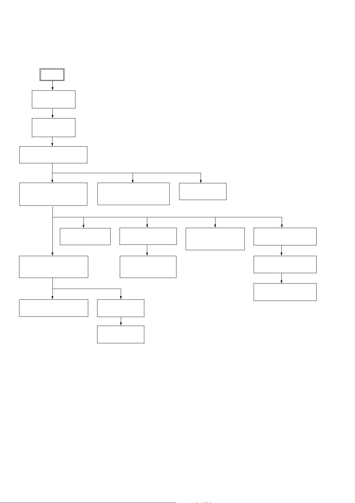
Note: Disassemble the unit in the order as shown below.
SET
3-1.COVER (TOP)
(Page 9)
3-2.CD DOOR
(Page 9)
SECTION 3
DISASSEMBLY
3-3.FRONT PANEL SECTION
(Page 10)
3-4.CD MECHANISM DECK
(CDM74-K6BD80)
(Page 10)
3-11.BD80A BOARD
(Page 14)
3-7.BACK PANEL SECTION,
SUB-TRANS BOARD
(Page 12)
3-8.POWER TRANSFORMER
(Page 12)
3-5.TAPE MECHANISM DECK,
GAME JACK BOARD
(Page 11)
3-12.CONNECT BOARD
(Page 14)
3-13.DRIVER BOARD,
SW BOARD
(Page 15)
3-9.MAIN BOARD
(Page 13)
3-6.PANEL BOARD
(Page 11)
3-14.OPTICAL PICK-UP
(KSM-215DCP/Z-NP)
(Page 15)
3-15.SENSOR BOARD
(Page 16)
3-16.MOTOR (TB) BOARD
(Page 16)
3-17.MOTOR (LD) BOARD
(Page 17)
3-10.AMP BOARD
(Page 13)
8
Note: Follow the disassembly procedure in the numerical order given.
HCD-GX250
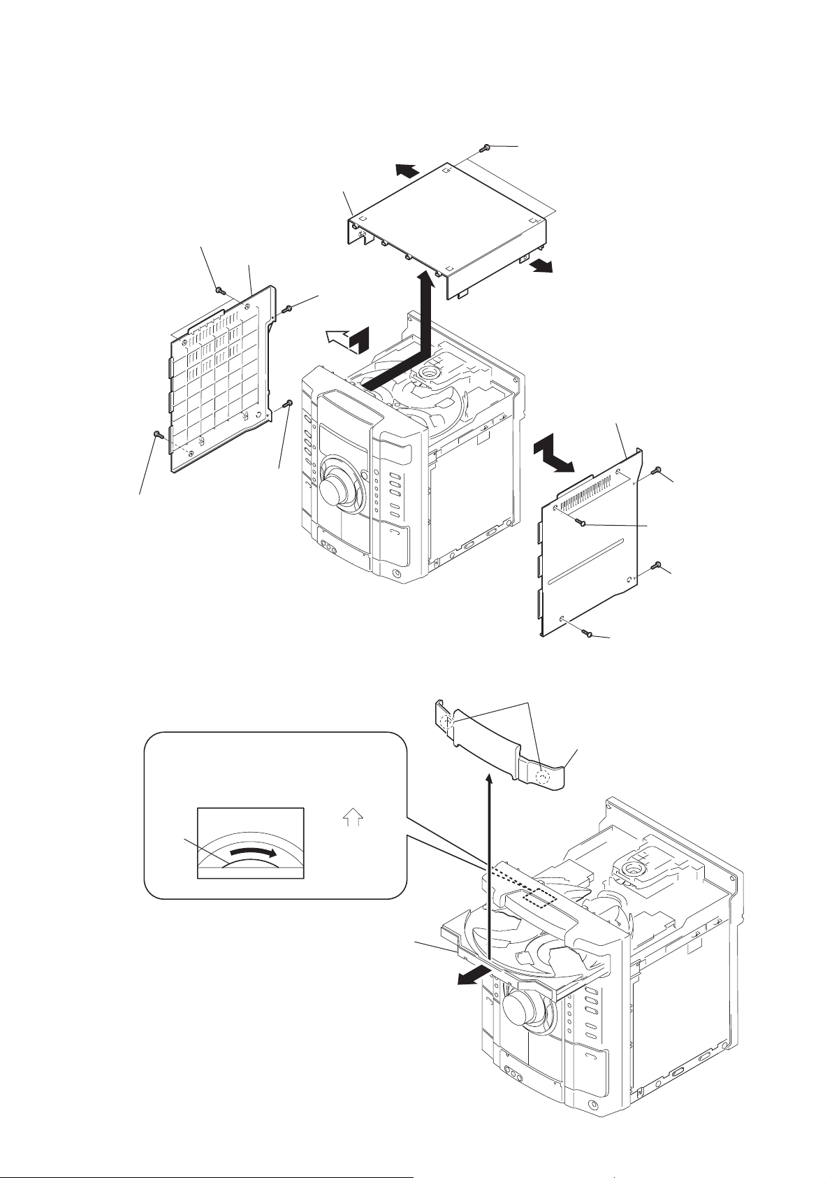
3-1. COVER (TOP)
6
two screws (Case 3 TP2)
7
screw (case 3 TP2)
cover
9
screw
(+BVTP 3
(Side-L)
× 10
)
qf
cover
8
(+BVTP 3
(top)
screw
q;
qs
× 10
qa
two
screws (+BVTP 3
qs
)
qd
5
cover
×
10)
(Side-R)
3
(+BVTP 3
1
two screws
(case 3 TP2)
screw
× 10
)
3-2. CD DOOR
CD mechanism deck (CDM74)
1
Turn the pulley to the direction of arrow.
pulley
Front panel side
2
Pull-out the disc tray.
3
two claws
4
CD door
4
(+BVTP 3
2
screw (Case 3 TP2)
screw
× 10
)
9
HCD-GX250
)
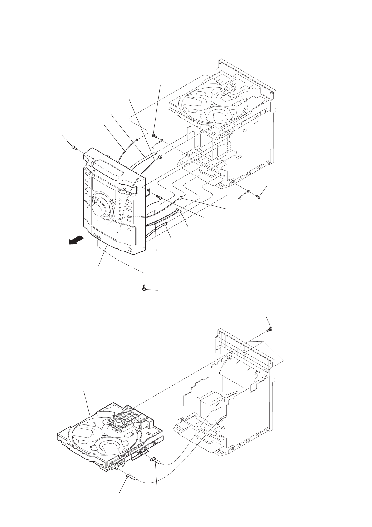
3-3. FRONT PANEL SECTION
0
connector 3p (CN304C)
8
wire (flat type) 7 core (CN253)
6
connector 2p (CN805)
3
screw (+BVTP 3
×
10)
4
screw (+BVTP 3
× 8
)
5
screw (+BVTP 3
× 8
)
qd
front panel section
3-4. CD MECHANISM DECK (CDM74-K6BD80)
4
CD mechanism deck (CDM74-K6BD80)
2
screw (+BVTP 3
qs
connector 8p (CN103)
9
connector 5p (CN309)
7
wire (flat type) 29 core (CN302)
1
three screws (+BVTP 3
qa
connector 3p (CN102B)
× 8
)
1
three
×
10)
screws (+BVTP 3
×
10
10
3
connector 9p (CN254)
2
connector 12p (CN701)
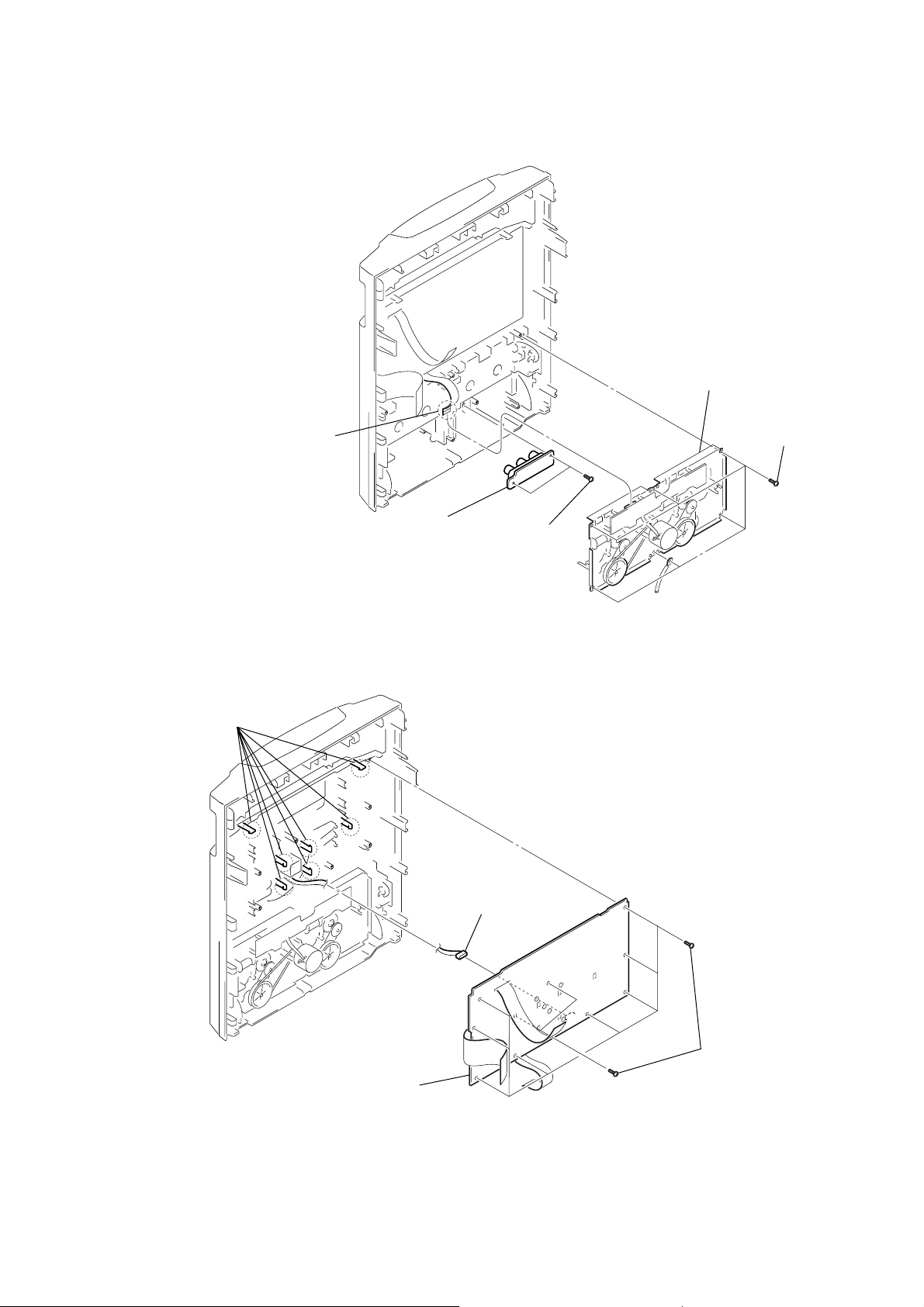
3-5. TAPE MECHANISM DECK, GAME JACK BOARD
)
)
1
wire (flat type) 13 core (CN602)
3
tape mechanism deck
HCD-GX250
2
six
screws
(+BVTP 2.6
×
8
3-6. PANEL BOARD
2
seven
claws
5
GAME JACK board
4
two
(+BVTP 2.6
3
connector 6p (CN604)
screws
×
8)
4
PANEL board
1
ten
screws
×
(+BVTP 2.6
8
11
HCD-GX250
)
r
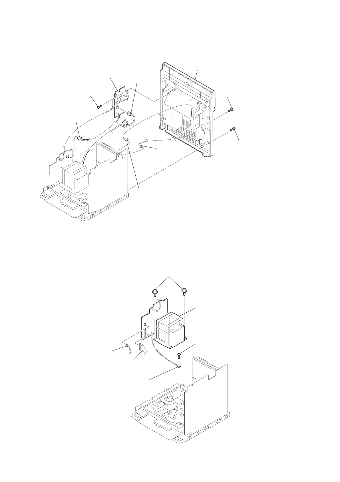
3-7. BACK PANEL SECTION, SUB-TRANS BOARD
7
8
SUB-TRANS board
6
(+BVTT 3
1
connector
2p (CN904)
two
screws
× 10
)
connector
2p (CN901)
3
connector
3p (CN308)
9
back panel section
5
(+BVTT 3
three
screws
×
10)
4
two
screws
(+BVTP 3
×
10
3-8. POWER TRANSFORMER
1
connector
3p (CN905)
2
wire (flat type) 11 core (CN101)
5
four
screws
(+ITC 4
× 8
)
6
power transforme
3
screw
(+BVIT 3
× 8R
)
12
2
connector
10p (CN907)
4
earth wire
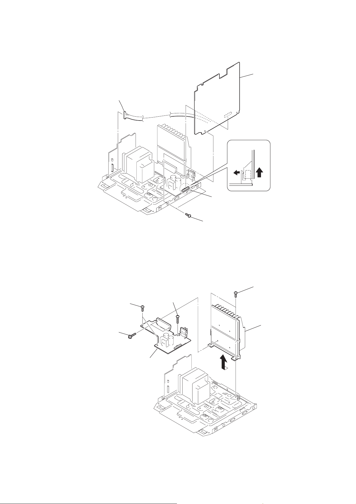
3-9. MAIN BOARD
d
)
1
connector
10p (CN907)
MAIN
4
MAIN
board
HCD-GX250
boar
3-10. AMP BOARD
3
two
screws
(+BVIT 3
4
two
screws
(transistor)
× 8R
)
6
AMP
2
screw
(+BVTP 3
board
×
14)
3
connector
13p (CN441)
2
two
screws
(+BVTP 3
× 8
)
1
two
screws
(+BVTT 3
5
heat sink
× 8
13
HCD-GX250
)
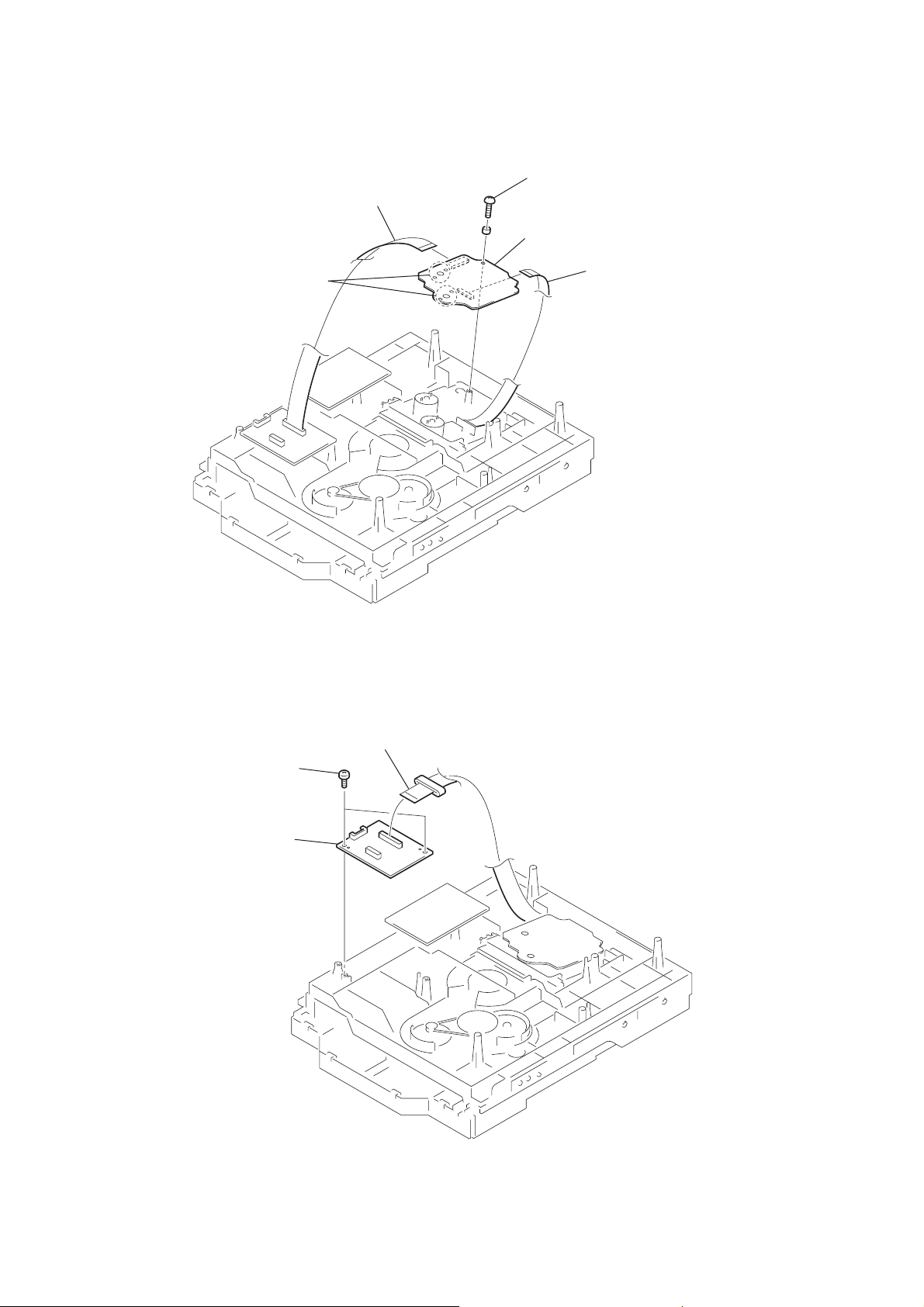
3-11. BD80A BOARD
4
Remove soldering from the four points.
1
wire (flat type) 17 core (CN201)
3
screw
(+BVTP 2.6
5
BD80A
board
× 8
)
2
wire (flat type) 16 core (CN101
3-12. CONNECT BOARD
2
two
(+BVTP 2.6
3
CONNECT
screws
board
1
wire (flat type) 17 core (CN201)
× 8
)
14
3-13. DRIVER BOARD, SW BOARD
1
(+BTTP (M2.6))
4
DRIVER
2
wire (flat type) 5p (CN702)
two
screws
board
3
connector
4p (CN703)
5
screw
(+BTTP (M2.6))
6
SW board
HCD-GX250
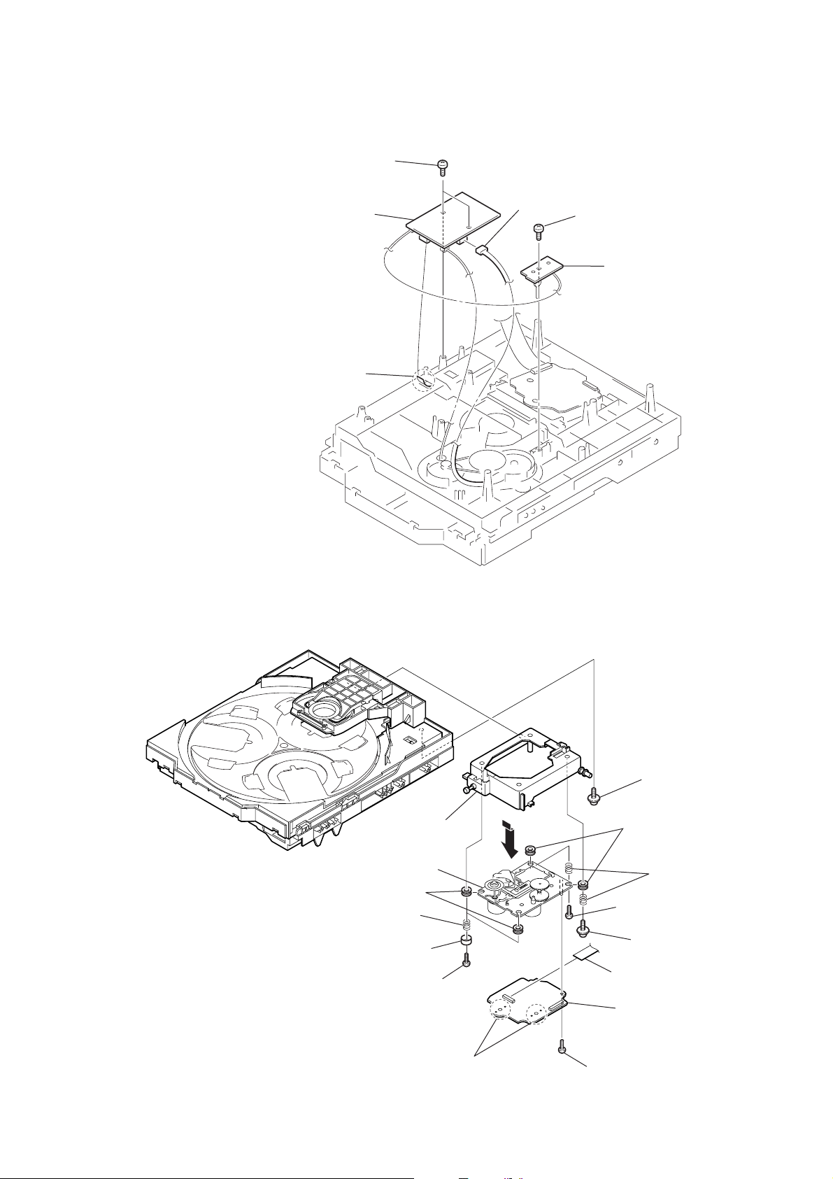
3-14. OPTICAL PICK-UP (KSM-213DCP/Z-NP)
2
qh
optical pick-up
(KSM-213DCP/Z-NP)
0
two
insulators
9
two
coil springs
(insulator)
8
t
wo stoppers (BU)
7
(BVTT M2.6)
h
older (213) ASSY
t
wo screws
qa
1
floating
(+PTPWH M2.6)
6
two
insulators
5
two
(insulator)
3
screw
(BVTT M2.6)
4
floating
(+PTPWH M2.6)
qf
CN101 (flat type)
qg
B
D80A board
screw
coil springs
screw
qd
Remove the four solderings of motor.
qs
s
crew (+BVTP 2.6x 8)
15
HCD-GX250
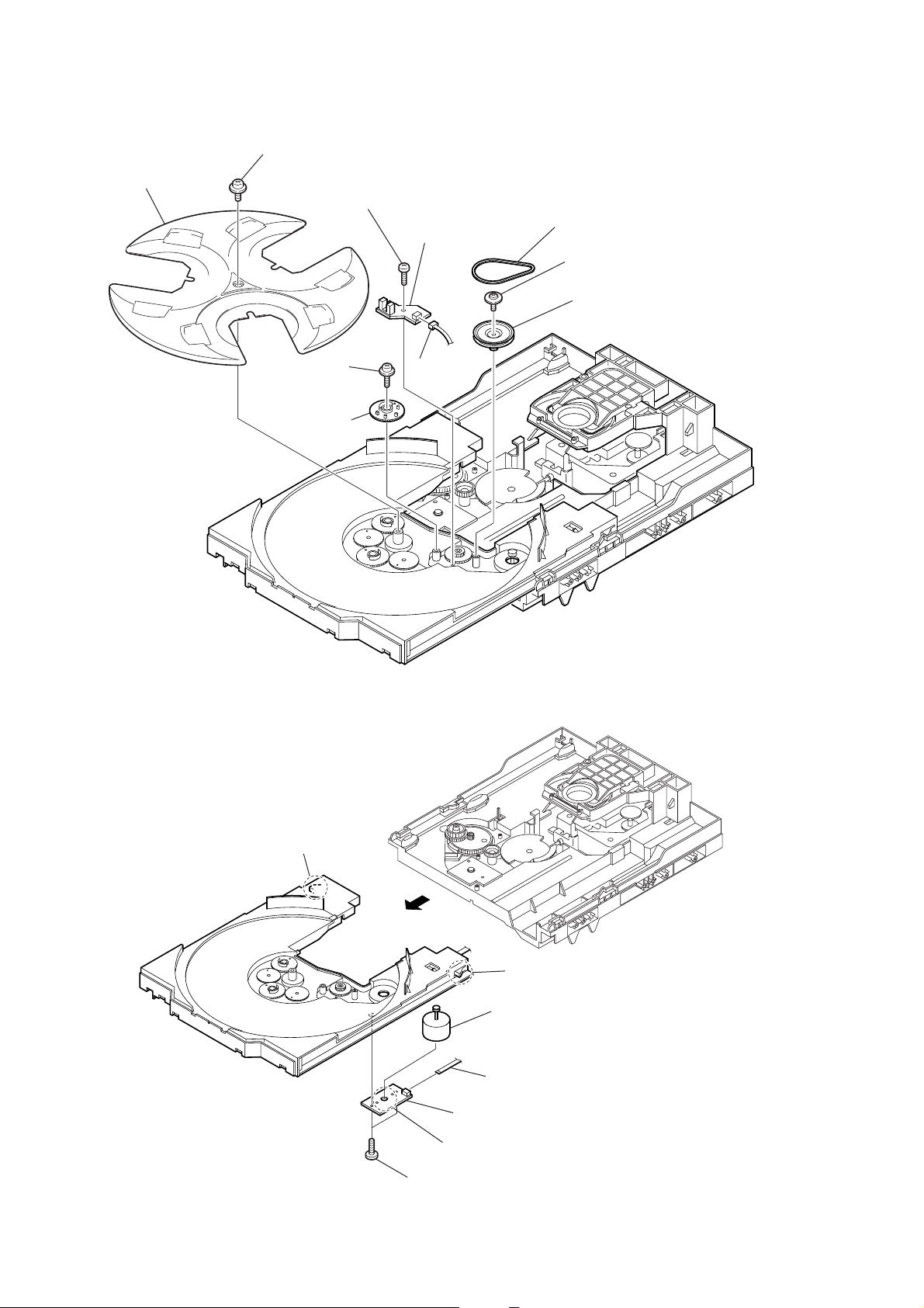
3-15. SENSOR BOARD
2
t
ray
1
floating
(+PTPWH M2.6)
6
floating
(+PTPWH M2.6)
7
g
screw
8
(+BTTP (M2.6))
screw
ear (geneva)
s
crew
0
SENSOR board
9
connector
CN731)
(
3
b
elt (table)
4
floating
(+PTPWH M2.6)
5
screw
p
ulley (table)
3-16. MOTOR (TB) BOARD
2
stopper
4
1
stopper
5
t
able motor assy (M741)
3
wire (flat type) 5 core (CN742)
7
MOTOR (TB) board
6
Remove the two solderings of motor.
16
5
two
screws
(+BTTP (M2.6))
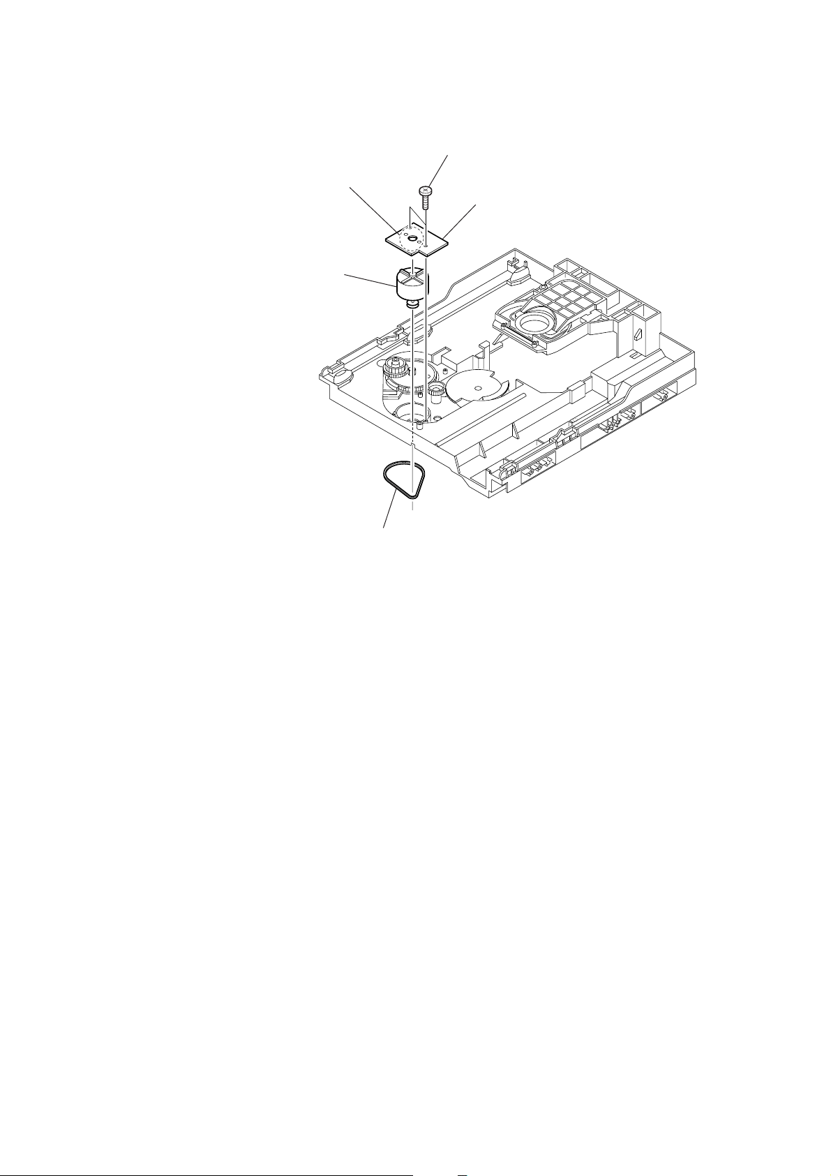
3-17. MOTOR (LD) BOARD
4
Remove the two solderings of motor.
5
l
oading motor assy (M751)
2
two
screws
(+BTTP (M2.6))
3
MOTOR (LD) board
HCD-GX250
1
b
elt (loading)
17
HCD-GX250
SECTION 4
TEST MODE
[Change-over of AM Tuner Step between 9 kHz and
10 kHz]
•A step of AM channels can be changed ov er between 9 kHz and
10 kHz.
Procedure:
1. Press ?/1 button to turn the set ON.
2. Select the function “TUNER”, and press TUNER/BAND
button to select the BAND “AM”.
3. Press ?/1 button to turn the set OFF.
4. Press TUNER/BAND and ? /1 buttons simultaneously, and
the display of fluorescent indicator tube changes to “AM 9 k
STEP” or “ AM 10 k STEP”, and thus the channel step is changed
over.
[Cold Reset]
• The cold reset clears all data including preset data stored in the
RAM to initial conditions. Execute this mode when returning
the set to the customer.
Procedure:
1. Press three buttons x , PLAY MODE/TUNING MODE ,
and DISC 1 simultaneously.
2. The fluorescent indicator tube displays “COLD RESET” and
the set is reset.
[Aging Mode]
This mode can be used for operation check of CD section and tape
deck section.
• If an error occurred:
The aging operation stops and is displayed status.
• If no error occurs:
The aging operation continues repeatedly.
1. Operating method of Aging Mode
Turn on the main power and select “CD” of the function.
1) Set three discs in tray. Select ALL DISCS, and REPEAT OFF.
2) Load the tapes recording use into both decks.
3) Press three buttons x , PLAY MODE/TUNING MODE ,
and EX-CHANGE simultaneously.
4) Aging operations of CD and tape are started at the same time.
5) To exit the aging mode, perform [Cold Reset].
2. Aging mode in CD section
1) Operation during aging mode
• In the agining mode ,the program is excuted in the following
sequence.
(1) The disc tray opens and closes.
(2) The disc tray turns to select a disc 3.
(3) The pick-up accesses to the first track, and plays 3 seconds.
(4) The pick-up accesses to the last track, and plays 3 seconds.
(5) The disc tray opens and closes.
(6) The disc tray turns to select a disc 1.
(7) The same operation starts like step (3).
(8) After a disc 1 aging operation, a disc 2 is selected.
(9) When an aging operation of a disc 3 is completed, the display
“AGING ∗∗∗∗” value increases.
(10) If no error occurs, the aging operation continues repeatedly.
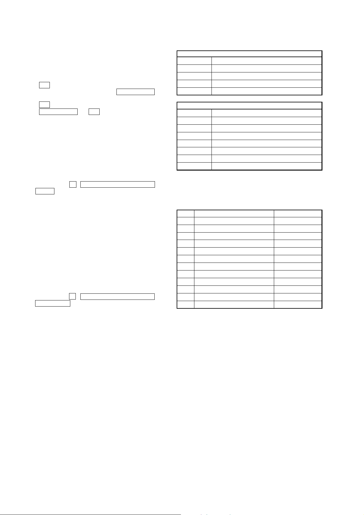
2) Error display
Disc error
Display Error
E00D01022 Focus error (No disc)
E00D02022 Sub Q error (Focus is good)
E00D02023 TOC reading error
E00D02014 Access error (Unable within regular time)
Mechanism error
Display Error
E00M__E_0 Error during opening tray
E00M__C_2 EX-CHANGE disc error
E00M__D_0 Error during closing tray
E00M__F_3 EX-OPEN error
E00M__D_5 EX-CLOSE error
E00M__C_2 Chuck-up error
E00M__C_3 Unchucking error
3. Aging mode in Tape Deck section
1) Operation during aging mode
• In the agining mode, the program is excuted in the following
sequence.
Step
1
Rewind the TAPE A
2
Rewind the TAPE B
3
Play the TAPE A (1 minute)
4
Stop the TAPE A (1 second)
5
Play the TAPE A (3 minutes)
6
Rewind(AMS) the TAPE A
7
F.F.(AMS) the TAPE A
8
Play the TAPE B (1 minute)
9
Stop the TAPE B (1 second)
10
Record the TAPE B (3 minutes)
11
Rewind(AMS) the TAPE B
12
F.F.(AMS) the TAPE B
Operation
Display
TAPE AAG-1
TAPE BAG-2
TAPE AAG-2
TAPE AAG-3
TAPE AAG-4
TAPE AAG-5
TAPE AAG-6
TAPE BAG-2
TAPE BAG-3
TAPE BAG-4
TAPE BAG-5
TAPE BAG-6
2) Error display
• If error occurred, the display remains like “TAPE BAG-2”.
4. Exiting from the aging mode
• Be sure to perform Cold Reset to exit from the aging mode.
18

HCD-GX250
[P ANEL Test Mode]
• All fluorecent segments and LEDs are tested.
•Keyboard check.
Procedure:
1. Press ?/1 button to turn the set ON.
2. To enter the test mode, press the three buttons x , PLAY
MODE/TUNING MODE and ENTER simultaneously.
3. All segments and LEDs (without STANDBY LED) are turned
on.
4. Press X and ENTER buttons simultaneously, and the key
check mode is activated.
5. The message “KEY 0 0 0 ” is displayed.
Each time a button is pressed, the key code number is displayed.
6. Press X and ENTER buttons simultaneously, and the key
count mode is activated.
7. The message “KEYCNT 0” is displayed.
Each time a button is pressed, “KEYCNT 0” value increased.
However, once a button is pressed, it is no longer taken into
account.
8. Press X and ENTER buttons simultaneously, and the head
phone detect mode is activated.
9. The message “H_P OFF” is displayed when a headphone jack
is not inserted.
“H_P ON ” is displayed when a headphone jack is inserted.
10. Press X and ENTER buttons simultaneously, and the volume
control detect mode is activated.
11. The message “VOLUME FLAT” is displayed.
“VOLUME UP” is displayed if rotating MASTER VOLUME
knob clockwise, or “VOLUME DO WN” is displayed if rotating
counterclockwise.
12. To exit from the GC test mode after the head phone detect mode,
press X and ENTER buttons simultaneously.
[Version and Destination Display Mode]
•The version or destination is displayed.
Procedure:
1. Press ?/1 button to turn the set ON.
2. To enter the test mode, press the three buttons x , PLAY
MODE/TUNING MODE and DISC 2 simultaneously.
3. The destination is displayed.
4. Press DISPLAY buttons simultaneously.
5. The version is displayed.
6. To exit from this mode, press ?/1 button to turn the set OFF.
[CD Service Mode]
•This mode can run the CD sled motor freely. Use this mode, for
instance, when cleaning the pick-up.
Procedure:
1. Press ?/1 button to turn the set ON.
2. Select the function “CD”.
3. To enter the test mode, press three buttons x , PLAY MODE/
TUNING MODE , and Z simultaneously.
4. The CD service mode is selected.
5. With the CD in stop status, press M button to move the
pick-up to outside track, or press m button to inside track.
6. To exit from this mode, perform as follows:
1) Move the pick-up to the most inside track.
2) Press ?/1 button to turn the set OFF.
Note: • Always move the pick-up to most inside track when exiting from
this mode. Otherwise, a disc will not be unloaded.
• Do not run the sled motor excessively, otherwise the gear can be
chipped.
[MC Test Mode]
•This mode is used to test the function of the equalizer.
Procedure:
1. Press ?/1 button to turn the set ON.
2. To enter the test mode, press the three buttons x , PLAY
MODE/TUNING MODE and DISC 3 simultaneously.
3. Press the EQ + button.
The function of the equalizer is set to “MIN”.
4. Press the EQ - button.
The function of the equalizer is set to “MAX”.
5. Press the PRESET EQ button.
The function of the equalizer is set to “EQ FLAT”.
6. MASTER VOLUME up and down.
“VOLUME MIN” “VOLUME 16” “VOLUME MAX” is
displayed.
7. Press the GROOVE button.
The message “VACS OFF” or “VACS ON” is displayed.
8. To exit from this mode, press ?/1 button to turn the set OFF.
[CD Ship Mode (LOCK) ]
•This mode moves the pick-up to the position durable to vibra-
tion. Use this mode when returning the set to the customer after
repair.
Procedure:
1. Press ?/1 button to turn the set ON.
2. Select the function “CD”.
3. Press ?/1 button to turn the set OFF.
4. Press CD button and ?/1 button simultaneously.
5. The “STANDBY” display blinks instantaneously, and the CD
ship mode is set.
[CD Ship (LOCK) & COLD RESET MODE]
Procedure:
1. Press ?/1 button to turn the set ON.
2. Select the function “CD”.
3. Press ?/1 button to turn the set OFF.
4. Press three buttons x , CD and DISPLAY simultaneously.
5. The “ST ANDBY” display blinks instantaneously and CD ship
mode is set.
6. To fluorescent indicator tube displays “COLD RESET” and
the set is reset.
[Disc T ray Lock]
Procedure:
1. Press the ?/1 button to turn the set ON.
2. Press two buttons of x and Z simultaneously for f ive seconds.
3. The message “LOCKED” is displayed and the tray is locked.
(Even if exiting from this mode, the tray is still locked.)
4. Press two buttons of x and Z simultaneously for five seconds
again.
5. The message “UNLOCKED” is displayed and the tray is
unlocked.
6. To exit from this mode, press the ?/1 button to turn the set
OFF.
19

HCD-GX250
[CD Repeat 5 Times Limit Release Mode]
Procedure:
1. Press ?/1 button to turn the set ON.
2. Select the function “CD”.
3. Press three buttons x , CD and ENTER simultaneously.
4. The message “LIMIT OFF” is displayed.
5. Press ?/1 button the set OFF.
[AMP TEST MODE]
Procedure:
1. Press ?/1 button to turn the set ON.
2. To enter the test mode, press three buttons x , PLAY
MODE/TUNING MODE and ENTER simultaneously.
3. Press the DISPLAY button.
The message “V0 0 0” “ 000” is displayed.
4. Press the GROOVE button.
The message “DBFB ON” “DBFB OFF” is displayed.
5. Press the SURROUND button.
The message “SURROUND ON” “SURROUND OFF” is
displayed.
6. Press the EQ BAND button.
The message “LOW” “MID” “HIGH” is displayed.
7. Press ?/1 button to turn the set OFF.
20
 Loading...