

Sony HCD-GTX888, HCD-GTX777, HCD-GTX787 User Manual
HCD-GTX777/GTX787/GTX888
HCD-GTX777/GTX787/GTX888
SERVICE MANUAL
Ver. 1.1 2008. 05
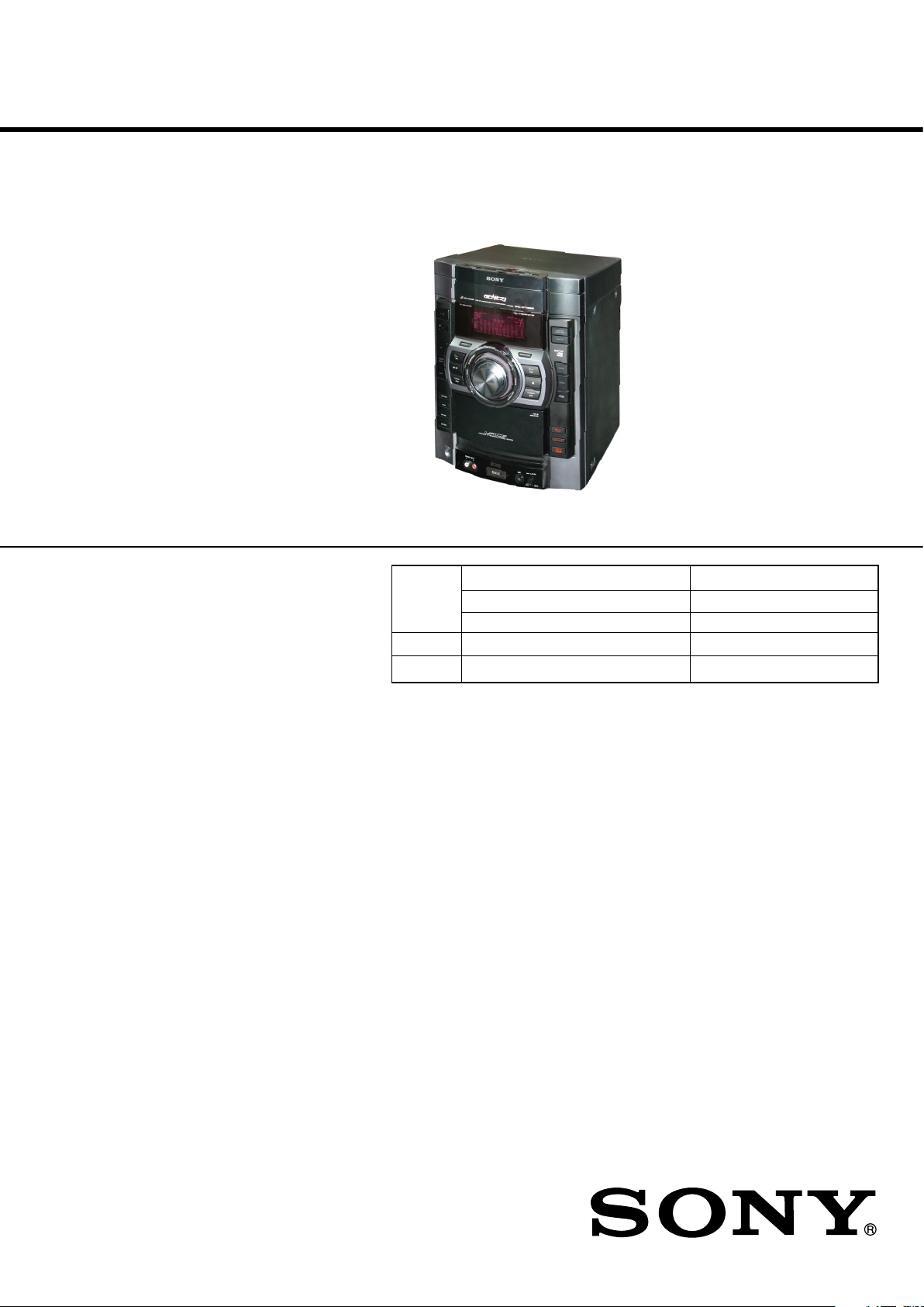
• HCD-GTX777/GTX787/GTX888
are the tuner, deck, CD and
amplifi er section in
MHC-GTX777/GTX787/GTX888.
Photo : HCD-GTX888 (E Model)
Model Name Using Similar Mechanism HCD-GTX66/GTX77/GTX88
CD CD Mechanism Type CDM74KF-K6BD93-WOD//M
Section
Tape Deck Model Name Using Similar Mechanism NEW
Section Tape Mechanism Type CFP42608
Optical Pick-up Name KSM-213DCP/C2NP
AEP Model
HCD-GTX777
E Model
HCD-GTX777/GTX787/GTX888
Australian Model
HCD-GTX888
AUDIO POWER SPECIFICATION
Amplifi er section
MHC-GTX888 (HCD-GTX888)
The following are measured at
Mexican model: AC 127 V, 60 Hz
Other models: AC 120, 220, 230 – 240 V, 50/60 Hz
Front/Surround speaker
Power Output (rated): 190 W + 190 W (at 8 Ω and 24 Ω,
1 kHz, 1% THD, at LINK MODE)
RMS output power (reference):
295 W + 295 W (per channel at 8 Ω and
24 Ω, 1 kHz, 10% THD, at LINK MODE)
Subwoofer
RMS output power (reference):
160 W + 160 W (per channel at 6 Ω,
100 Hz, 10% THD)
SPECIFICATIONS
MHC-GTX787 (HCD-GTX787)
The following are measured at
Mexican model: AC 127 V, 60 Hz
Other models: AC 120, 220, 230 – 240 V, 50/60 Hz
Front speaker
Power Output (rated): 230 W + 230 W (at 4 Ω, 1 kHz, 1% THD)
RMS output power (reference):
380 W + 380 W (per channel at 4 Ω, 1 kHz, 10% THD)
MHC-GTX777 (HCD-GTX777)
European model only
The following are measured at
AC 230 V, 50/60 Hz
Front/Surround speaker
Power Output (rated): 235 W + 235 W (at 8 Ω and 8 Ω, 1 kHz,
1% THD, at LINK MODE)
RMS output power (reference):
380 W + 380 W (per channel at 8 Ω and
8 Ω, 1 kHz, 10% THD, at LINK MODE)
– Continued on next page –
CD DECK RECEIVER
9-890-504-02
2008E08-1
© 2008. 05
Sony Corporation
Audio Business Group
Published by Sony EMCS (Malaysia) PG Tec
1

HCD-GTX777/GTX787/GTX888
Other models
The following are measured at
AC 120, 220, 230 – 240 V, 50/60 Hz
Front/Surround speaker
Power Output (rated): 235 W + 235 W (at 8 Ω and 8 Ω, 1 kHz,
1% THD, at LINK MODE)
RMS output power (reference):
380 W + 380 W (per channel at 8 Ω and
8 Ω, 1 kHz, 10% THD, at LINK MODE)
Inputs
VIDEO (AUDIO IN) L/R:
Voltage 250 mV, impedance 47 kilohms
AUDIO INPUT L/R: Voltage 450 mV, impedance 47 kilohms
MIC: Sensitivity 1 mV, impedance 10 kilohms
(USB) port: Type A
Outputs
PHONES: accepts headphones of 8 Ω or more
Disc player section
System Compact disc and digital audio system
Laser Semiconductor laser
(λ = 770 – 810 nm)
Emission duration: continuous
Laser Output Max. 44.6 µW*
* This output is the value measured at
a distance of 200 mm from the
objective lens surface on the Optical
Pick-up Block with 7 mm aperture.
Frequency response 20 Hz – 20 kHz
Wave length 770 – 810 nm
Signal-to-noise ratio More than 90 dB
Dynamic range More than 88 dB
Tape deck section
Recording system 4-track 2-channel stereo
Frequency response 50 – 13,000 Hz (±3 dB),
using Sony TYPE I tape
Wow and fl utter ±0.35% W.Peak (IEC)
0.3% W.RMS (NAB)
±0.4% W.Peak (DIN)
Tuner section
FM stereo, FM/AM superheterodyne tuner
FM tuner section
Tuning range
Brazil model: 87.5 – 108.0 MHz (100 kHz step)
Other models: 87.5 – 108.0 MHz (50 kHz step)
Antenna FM lead antenna
Antenna terminals 75 ohms unbalanced
Intermediate frequency 10.7 MHz
AM tuner section
Tuning range Pan-American and Oceanian models:
530 – 1,710 kHz (with the interval set at 10 kHz)
531 – 1,710 kHz (with the interval set at 9 kHz)
European model: 531 – 1,602 kHz (with the interval set at 9 kHz)
Other models: 531 – 1,602 kHz (with the interval set at 9 kHz)
530 – 1,610 kHz (with the interval set at 10 kHz)
Antenna AM loop antenna
Antenna terminals External antenna terminal
Intermediate frequency 450 kHz
USB section
Supported bit rate MP3 (MPEG 1 Audio Layer 3): 32 – 320 kbps, VBR
WMA: 32 – 192 kbps, VBR AAC: 48 – 320 kbps
Sampling frequencies MP3 (MPEG 1 Audio Layer 3): 32/44.1/48 kHz
WMA: 44.1 kHz, AAC: 44.1 kHz
Transfer speed Full-Speed
Supported USB device Mass Storage Class
Maximum current 500 mA
General
Power requirements
European model: 230 V AC, 50/60 Hz
Mexican model: 127 V AC, 60 Hz
Oceanian model: 230 – 240 V AC, 50/60 Hz
Argentina models: 220 V AC, 50/60 Hz
Other models: 120 V, 220 V or 230 – 240 V AC, 50/60 Hz,
adjustable with voltage selector
Power consumption MHC-GTX888: 430 W
MHC-GTX787/MHC-GTX777: 300 W
Dimensions (w/h/d) (Approx.)
HCD-GTX888/HCD-GTX787/
HCD-GTX777: 281 × 365 × 454 mm
(11 1/8 × 14 3/8 × 17 7/8 inches)
Mass (Approx.) HCD-GTX888: 14.0 kg (30 lb 14 oz)
HCD-GTX787/HCD-GTX777:
12.0 kg (26 lb 8 oz)
Supplied accessories Remote Commander (1)
R6 (size AA) batteries (2)
AM loop antenna (1)
FM lead antenna (1)
Front speaker pads (8)
Surround speaker pads
(MHC-GTX888/MHC-GTX777 only) (8)
Subwoofer pads (MHC-GTX888 only) (Black) (8)
Speaker cords (MHC-GTX787 only) (2)
Spacer A (MHC-GTX888 only) (2)
Spacer B (MHC-GTX888 only) (2)
Spacer C (MHC-GTX777 only) (2)
Audio cable (1) (Mexico only)
Design and specifi cations are subject to change without notice.
SAFETY-RELATED COMPONENT WARNING!!
COMPONENTS IDENTIFIED BY MARK 0 OR DOTTED LINE
WITH MARK 0 ON THE SCHEMATIC DIAGRAMS AND IN THE
PARTS LIST ARE CRITICAL TO SAFE OPERATION. REPLACE
THESE COMPONENTS WITH SONY PARTS WHOSE PART
NUMBERS APPEAR AS SHOWN IN THIS MANUAL OR IN
SUPPLEMENTS PUBLISHED BY SONY.
2
HCD-GTX777/GTX787/GTX888
Notes on Chip Component Replacement
• Never reuse a disconnected chip component.
• Notice that the minus side of a tantalum capacitor may be
damaged by heat.
Flexible Circuit Board Repairing
• Keep the temperature of soldering iron around 270°C during
repairing.
• Do not touch the soldering iron on the same conductor of the
circuit board (within 3 times).
• Be careful not to apply force on the conductor when soldering or
unsoldering.
UNLEADED SOLDER
Boards requiring use of unleaded solder are printed with the lead
free mark (LF) indicating the solder contains no lead.
(Caution: Some printed circuit boards may not come printed with
the lead free mark due to their particular size)
: LEAD FREE MARK
Unleaded solder has the following characteristics.
• Unleaded solder melts at a temperature about 40 °C higher than
ordinary solder.
Ordinary soldering irons can be used but the iron tip has to be
applied to the solder joint for a slightly longer time.
Soldering irons using a temperature regulator should be set to
about 350 °C.
Caution: The printed pattern (copper foil) may peel away if the
heated tip is applied for too long, so be careful!
• Strong viscosity
Unleaded solder is more viscou-s (sticky, less prone to fl ow) than
ordinary solder so use caution not to let solder bridges occur such
as on IC pins, etc.
• Usable with ordinary solder
It is best to use only unleaded solder but unleaded solder may also
be added to ordinary solder.
NOTES ON LASER DIODE EMISSION CHECK
The laser beam on this model is concentrated so as to be focused on
the disc refl ective surface by the objective lens in the optical pick-up
block. Therefore, when checking the laser diode emission,
observe from more than 30 cm away from the objective lens.
Laser component in this product is capable
of emitting radiation exceeding the limit for
Class 1.
This appliance is
claassifi ed as a CLASS 1
LASER product. This
label is located on the
rear exterior.
CAUTION
Use of controls or adjustments or performance of procedures
other than those specifi ed herein may result in hazardous
radiation exposure.
NOTES ON HANDLING THE OPTICAL PICK-UP BLOCK
OR BASE UNIT
The laser diode in the optical pick-up block may suffer electrostatic
breakdown because of the potential difference generated by the
charged electrostatic load, etc. on clothing and the human body.
During repair, pay attention to electrostatic break-down and also
use the procedure in the printed matter which is included in the
repair parts.
The fl exible board is easily damaged and should be handled with
care.
3
HCD-GTX777/GTX787/GTX888
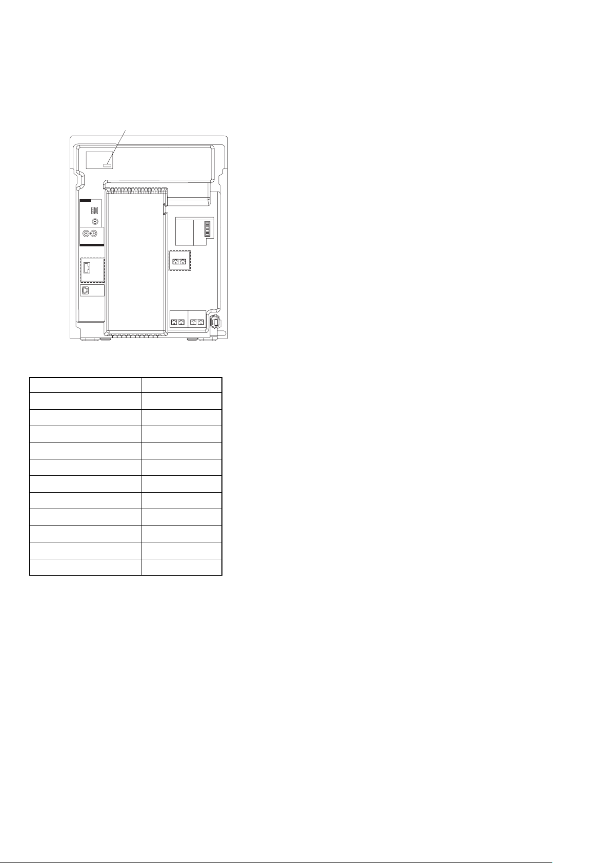
MODEL IDENTIFICATION
– MODEL NUMBER LABEL –
PART NO
(GTX888 ONLY)
• Abbreviation
E2 : 120V AC area in E model
E3 : Middle Easten, African and Indian model
E51 : Chilean and Peruvian model
AR : Argentina model
AUS : Australian model
MX : Mexican model
(GTX888 ONLY)
MODEL Parts No
GTX888: E2, E51
GTX777: E2, E51
GTX787: E2
GTX777: AEP
GTX888: AR
GTX777: AR
GTX888: AUS
GTX888: E3
GTX777: E3
GTX888: MX
GTX777: MX
3-290-078-0s
3-290-078-1s
3-290-078-2s
3-290-079-1s
3-873-456-0s
3-873-456-1s
3-873-457-0s
3-873-458-0s
3-873-458-1s
3-873-459-0s
3-873-459-1s
4

TABLE OF CONTENTS
HCD-GTX777/GTX787/GTX888
1. GENERAL
Guide to parts and controls ...................................................... 6
2. DISASSEMBLY
2-1. Case (Top) .......................................................................... 13
2-2. Loading Panel .................................................................... 13
2-3. CD Block Section .............................................................. 14
2-4. Front Panel Section ............................................................ 14
2-5. Tape Mechanism Deck, Mic Board,
USB Connector Board ....................................................... 15
2-6. Panel Board, Function Board, Jog Board .......................... 15
2-7. CD-SW Board .................................................................... 16
2-8. Cover (CDM) ..................................................................... 16
2-9. Tuner Pack ......................................................................... 17
2-10. Back Panel Section, Sub Trans Board ............................... 17
2-11. Main Board ....................................................................... 18
2-12. Power Board Section ......................................................... 18
2-13. Subwoofer Board, Power Board ........................................ 19
2-14. Power Transformer (T1200) .............................................. 19
2-15. BD93 Board ....................................................................... 20
2-16. Driver Board, SW Board, USB Board ............................... 20
2-17. Optical Pick-up .................................................................. 21
2-18. Sensor Board ...................................................................... 21
2-19. Motor (TB) Board .............................................................. 22
2-20. Motor (LD) Board ............................................................. 22
3. TEST MODE .............................................................. 23
4. MECHANICAL ADJUSTMENTS ......................... 27
5. ELECTRICAL ADJUSTMENTS ..........................28
6. DIAGRAMS
6-1. Block Diagram — RF/Servo Section — ........................... 31
6-2. Block Diagram — Tape/Tuner Section — ......................... 32
6-3. Block Diagram — Main Section — .................................. 33
6-4. Block Diagram — USB Section — ................................... 34
6-5. Block Diagram — AMP/Subwoofer Section — ................ 35
6-6. Block Diagram — Display/Power Section — ................... 36
6-7. Circuit Boards Location ..................................................... 37
6-8. Printed Wiring Board — BD93 Board — ......................... 40
6-9. Schematic Diagram — BD93 Board — ............................ 41
6-10. Printed Wiring Boards — Driver Board — ....................... 42
6-11. Schematic Diagram — Driver Board — ........................... 43
6-12. Printed Wiring Board — Main Board — ........................... 44
6-13. Schematic Diagram — Main Board (1/4) — ..................... 45
6-14. Schematic Diagram — Main Board (2/4) — ..................... 46
6-15. Schematic Diagram — Main Board (3/4) — ..................... 47
6-16. Schematic Diagram — Main Board (4/4) — ..................... 48
6-17. Printed Wiring Board — USB Board — ........................... 49
6-18. Schematic Diagram — USB Board — .............................. 50
6-19. Printed Wiring Board — Panel Function Board — ........... 51
6-20. Schematic Diagram — Panel Function Board — .............. 52
6-21. Printed Wiring Board — Power Board — ......................... 53
6-22. Schematic Diagram — Power Board — ............................ 54
6-23. Printed Wiring Board — Sub Woofer Board — ................ 55
6-24. Schematic Diagram — Sub Woofer Board — ................... 56
6-25. Printed Wiring Boards — Trans Board — ......................... 57
6-26. Schematic Diagram — Trans Board — ............................. 58
6-27. Printed Wiring Board — Illumination Board — ............... 59
6-28. Schematic Diagram — Illumination Board — .................. 60
6-29. Printed Wiring Board — MIC Board — ........................... 61
6-30. Schematic Diagram — MIC Board — .............................. 62
6-31. Printed Wiring Boards — TC Board — ............................ 63
6-32. Schematic Diagram — TC Board — ................................. 64
6-33. Printed Wiring Boards — Meter Display Board — .......... 65
6-34. Schematic Diagram — Meter Display Board — ............... 66
7. EXPLODED VIEWS
7-1. Main Section ...................................................................... 80
7-2. Back Panel Section ............................................................ 81
7-3. Front Panel Section (1) ...................................................... 82
7-4. Front Panel Section (2) ...................................................... 83
7-5. Meter Display Assy ........................................................... 84
7-6. Chassis Section .................................................................. 85
7-7. CD Mechanism Section (1) ............................................... 86
7-8. CD Mechanism Section (2) ............................................... 87
8. ELECTRICAL PARTS LIST ................................. 88
5
HCD-GTX777/GTX787/GTX888
XLX
X
X
SECTION 1
GENERAL
Note:
This section is extracted
from instruction manual.
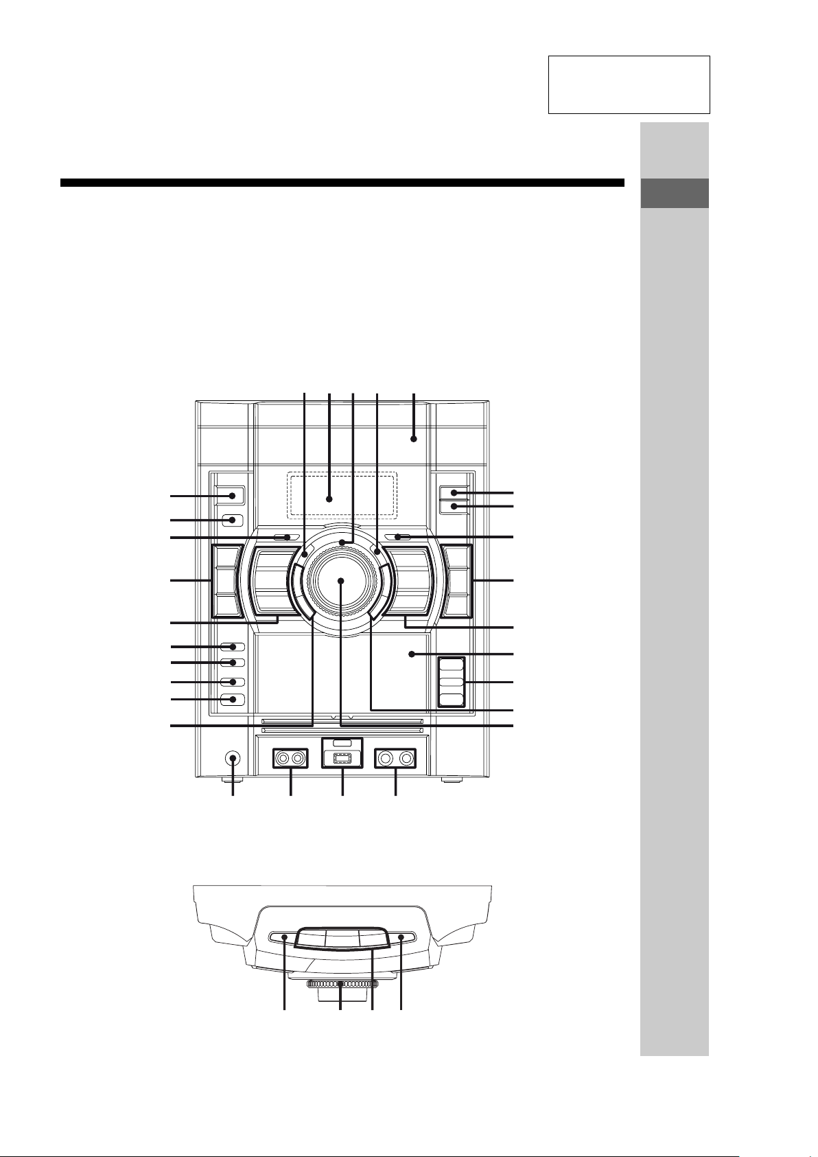
Guide to parts and controls
This manual mainly explains operations using the buttons on the unit, but the same
operations can also be performed using the buttons on the remote having the same or
similar names.
Unit
– Front view
Guide to parts and controls
– Top view
XH
XG
XE
R
XT
XB
X
RM
RE
RKRL RI
R
RB
RT
RE
RG
RH
M
6
K
I
Continued
M
HCD-GTX777/GTX787/GTX888
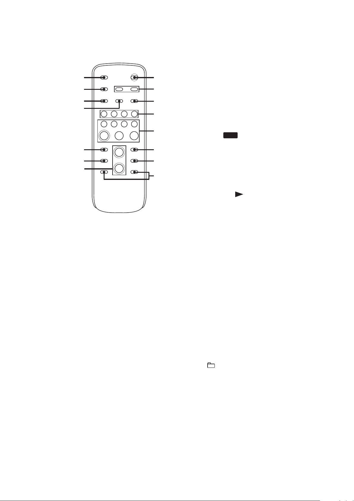
Remote
FI
XE
FH
FG
FE
FT
RG
" EQ BAND/MEMORY (page 38)
Press to select a frequency band.
# Display (pages 11, 31, 32, 48)
Meter display (page 32)
$ Power illuminator (pages 31, 32)
XH
F
FB
R
RM
XM
R
) METER MODE (page 32)
Press to select a preset display
pattern.
* Function buttons:
CD (pages 15, 20, 24, 32, 33, 36)
TUNER/BAND (pages 22, 32)
Unit: TAPE (pages 29, 32)
Unit: AUDIO (pages 29, 32)
Unit: VIDEO (pages 29, 32)
Unit: (pages 25, 27, 32, 33)
USB
Remote: USB (pages 25, 27, 33)
Remote: FUNCTION (page 29)
Press to select a function.
+ Unit: /9 (play/pause)
(pages 20, 24, 27, 29, 44)
Remote: (play) (pages 20,
27, 29, 44)
Remote: 9 (pause) (pages 20,
29)
Press to start or pause playback.
Y (stop) (pages 20, 22, 27, 29,
37, 43)
Press to stop playback, recording or
transferring.
% PRESET EQ (pages 30, 38)
Press to select a preset sound effect.
& Disc tray (pages 11, 20, 43, 48)
' SURROUND SPEAKER MODE
(MHC-GTX888 only) (page 30)
Press to select the sound system.
SURROUND
(MHC-GTX787/MHC-GTX777
only) (page 30)
Press to select the surround effect.
( GROOVE (page 30)
Press to reinforce the bass.
(go backward/go
forward) (pages 20, 27, 34)
Press to select a track or file.
Unit: TUNING +/– (page 22)
Remote: +/– (tuning) (pages 22,
35)
Press to tune in a radio station.
+/– (pages 20, 27, 33, 36)
Press to select a folder.
N.(rewind/fast forward)
(pages 20, 28, 29)
Unit: Press to fast forward or rewind.
Remote: Press to find a point in a
track or file.
7
HCD-GTX777/GTX787/GTX888
, PUSH ;OPEN/CLOSE
(page 29)
Press to insert or eject a tape.
Tape deck (pages 29, 36, 40, 47)
- REC TO TAPE (page 37)
Press to record onto a tape.
REC TIMER (page 40)
Press to set the Recording Timer.
REC TO (page 24)
Press to transfer onto the connected
optional USB device.
. FLANGER (pages 31, 43, 47)
DELAY (pages 31, 43, 47)
CHORUS (pages 31, 43, 47)
SOUND FLASH (page 31)
Press to create a party atmosphere.
/ Unit: MASTER VOLUME
(pages 20, 27, 29, 31, 42)
Turn to adjust the volume.
Remote: VOLUME +/–*
(pages 20, 27, 29, 31, 42)
Press to adjust the volume.
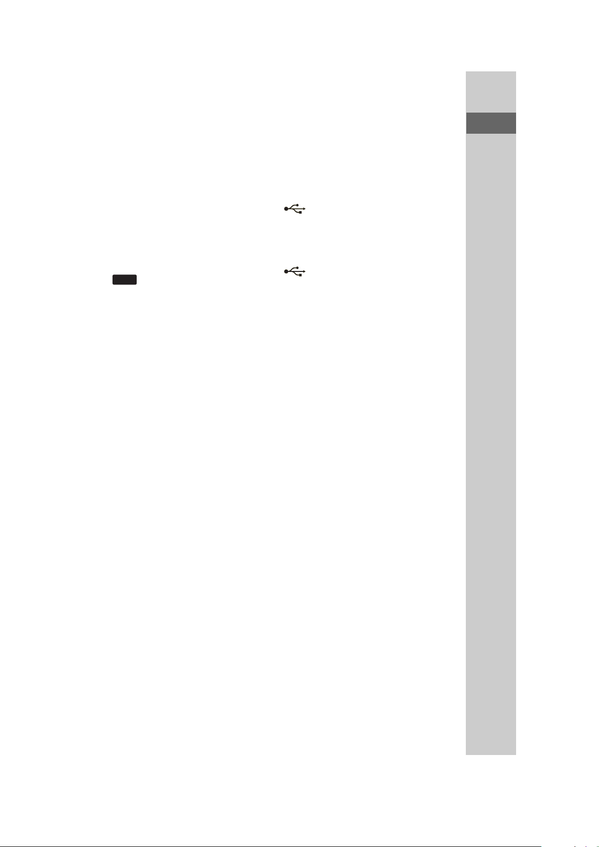
USB
0 MIC (jack) (pages 39, 42, 53)
Connect an optional microphone.
MIC LEVEL (pages 37, 39, 42)
Turn to adjust the microphone
volume.
1 (indicator)
Lights up when transferring to the
connected optional USB device, or
when erasing audio files or folders.
(USB) port (pages 23, 25,
27, 46, 53)
Connect an optional USB device.
2 AUDIO INPUT L/R (jacks)
(page 29)
Connect to an audio component
(Portable audio player, etc.).
3 PHONES (jack) (pages 42, 53)
Connect the headphones.
4 ENTER (pages 20, 27, 30, 31,
34, 35, 38)
Press to enter the selection.
5 RETURN (page 20)
Press to return to the parent folder.
Press to exit search mode.
Guide to parts and controls
* The VOLUME + button has a tactile dot.
Use the tactile dot as a reference when
operating the system.
6 ERASE (page 25)
Press to erase audio files or folders
on the connected optional USB
device.
Continued
M
8

HCD-GTX777/GTX787/GTX888
7 OPTIONS (pages 30, 31)
Press to select the display pattern,
MP3 BOOSTER+ function and USB
SELECT.
8 DISPLAY (pages 19, 32, 32, 36)
Press to change the information in
the display.
9 IR Receptor (page 42)
: (on/standby) (pages 14, 15,
42, 48)
Press to turn the system on or off.
; OPEN/CLOSE ; (pages 15, 20,
43)
Press to load or eject a disc.
XK DISC 1 ~ 3 (pages 21, 33)
Press to select a disc.
Press to switch to CD function from
other function.
XL OPERATION DIAL (pages 20,
27, 31, 38)
Turn to select a track, file or folder.
Turn to select a setting.
XM Unit: DISC SKIP/EX-CHANGE
(pages 15, 20, 21, 33)
Press to select a disc.
Press to exchange other discs during
playback.
F CLOCK/TIMER SELECT
(page 40)
CLOCK/TIMER SET (pages 19,
40)
Press to set the clock and the timers.
F[ REPEAT/FM MODE (pages 20,
23, 28, 47)
Press to change the Repeat Play
setting.
Press to select the FM monaural or
stereo reception.
FT EQ (pages 30, 38)
Press to select a preset sound effect.
FE CLEAR (page 34)
Press to delete a pre-programmed
track.
FG PLAY MODE/TUNING MODE
(pages 21, 22, 28, 33, 35, 37, 44,
48)
Press to select the play mode of CD
or USB function.
Press to select the tuning mode.
FH TUNER MEMORY (page 35)
Press to preset a radio station.
FI SLEEP (page 39)
Press to activate the Sleep Timer.
Remote: DISC SKIP (pages 21,
33)
Press to select a disc.
9
HCD-GTX777/GTX787/GTX888
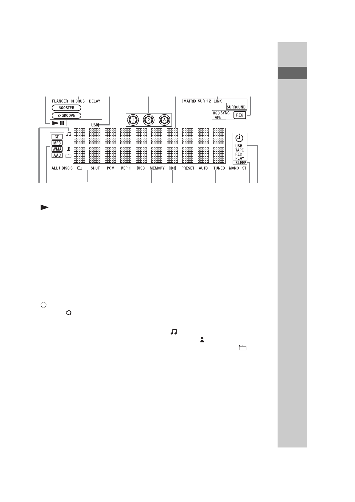
– Display
Guide to parts and controls
RERG
" “ ” lights up during playback.
“/9” lights up when playback is
paused.
# Indicates the activated sound effect
(pages 30, 31, 38).
Note
“LINK”, “MATRIX SUR 1” and
“MATRIX SUR 2” light up for
MHC-GTX888 only.
$ Lights up when the USB function is
selected (page 27).
% Indicators for the disc tray (page 20).
“ ” lights up when the disc is
selected. “ ” lights up when there is
a disc on the disc tray. “1”, “2” and
“3” light up when the system is turned
on.
& Displays the current status and
information (page 32).
' Lights up during transferring onto an
USB device or recording onto a tape
(pages 23, 36).
RBRT
R
( Lights up when the timer is set
(page 39).
) Lights up when the Sleep Timer is
activated (page 39).
* Indicators for the TUNER function
(pages 22, 35).
+ Lights up when the MP3 file contains
ID3 tag information.
, Lights up when an optional USB
device is recognized (page 23).
- Indicates the selected play mode
(pages 21, 28).
. Indicates the type of disc or file that
the system recognized.
/ Indicates the type of audio file
information that displayed (page 32).
“ ” lights up when a file name is
displayed. “ ” lights up when an
artist name is displayed. “ ” lights
up when a folder name is displayed.
10
Using the subwoofers
(MHC-GTX888 only)
You can use the subwoofers to enhance
the bass.
Subwoofer A (SS-WG888A)
1 Press SUBWOOFER ON/OFF on
the subwoofer A to light up the
indicator.
HCD-GTX777/GTX787/GTX888
The subwoofers are turned on.
2 Turn SUBWOOFER LEVEL on the
subwoofer A to adjust the level.
11
HCD-GTX777/GTX787/GTX888
SECTION 2
DISASSEMBLY
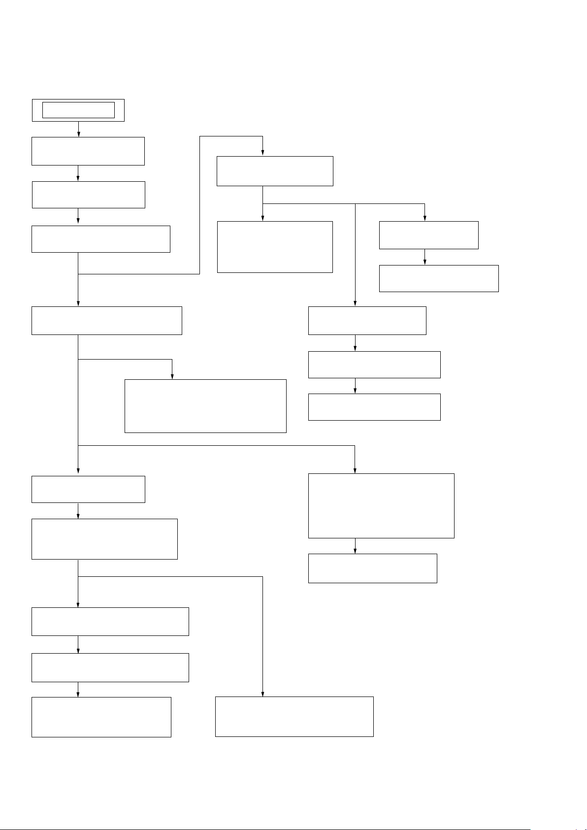
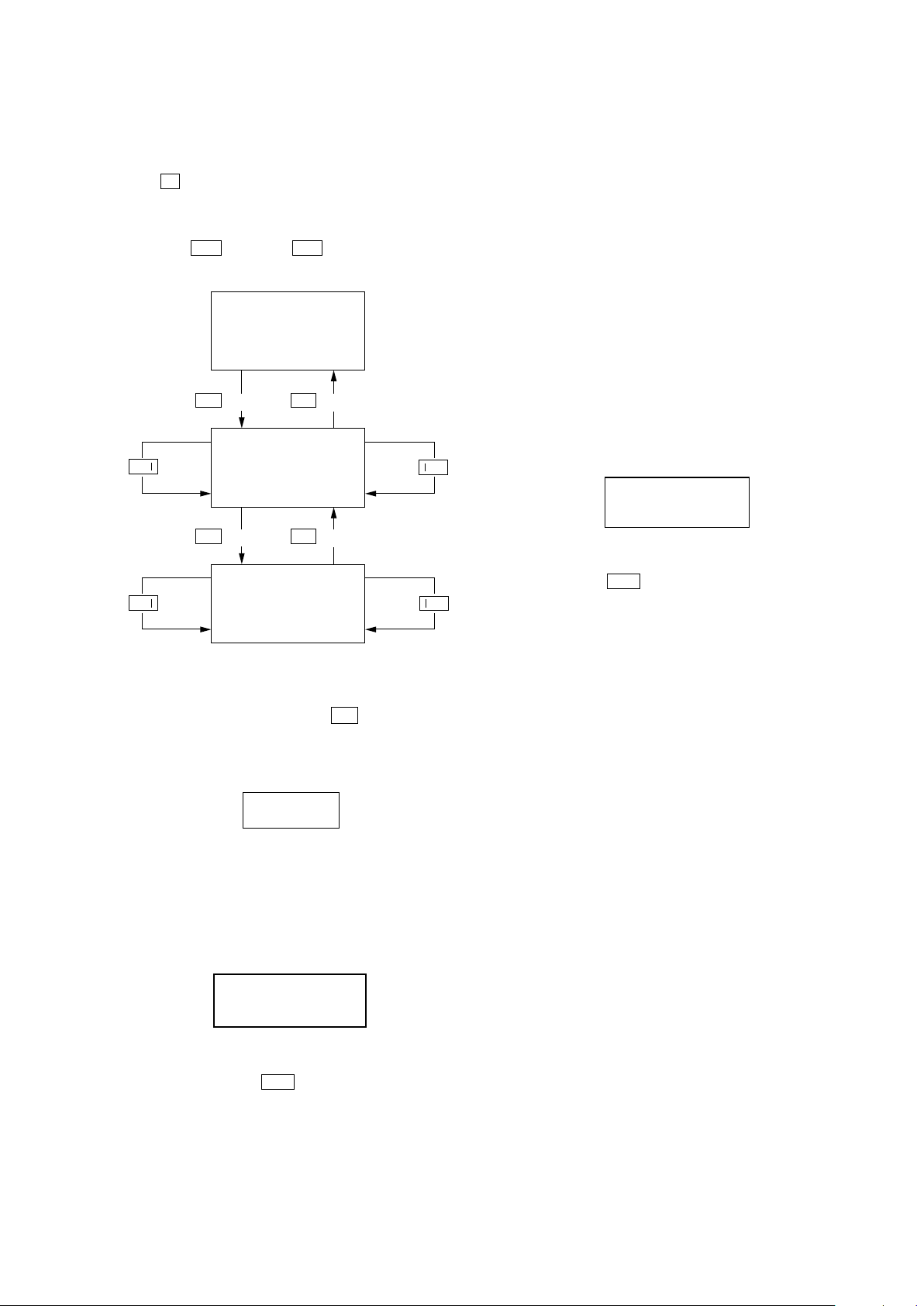
Note : This set can be disassembled in the order shown below.
SET
2-1. CASE (TOP)
(Page 13)
2-2. LOADING PANEL
(Page 13)
2-8. COVER (CDM)
(Page 16)
2-3. CD BLOCK SECTION
(Page 14)
2-4. FRONT PANEL SECTION
(Page 14)
2-5. TAPE MECHANISM DECK,
MIC BOARD,
USB CONNECTOR BOARD
(Page 15)
2-9. TUNER PACK
(Page 17)
2-10. BACK PANEL SECTION,
SUB TRANS BOARD
(Page 17)
2-16. DRIVER BOARD,
SW BOARD,
USB BOARD
(Page 20)
2-18. SENSOR BOARD
(Page 21)
2-19. MOTOR (TB) BOARD
(Page 22)
2-20. MOTOR (LD) BOARD
(Page 22)
2-6. METER DISPLAY ASSY
PANEL BOARD,
FUNCTION BOARD,
JOG BOARD
(Page 15)
2-7. CD-SW BOARD
(Page 16)
2-15. BD93 BOARD
(Page 20)
2-17. OPTICAL PICK-UP
(Page 21)
2-11. MAIN BOARD
(Page 18)
2-12. POWER BOARD SECTION
(Page 18)
2-13. SUBWOOFER BOARD,
POWER BOARD
(Page 19)
12
2-14. POWER TRANSFORMER
(T1200)
(Page 19)
Note : Follow the disassembly procedure in the numerical order given.
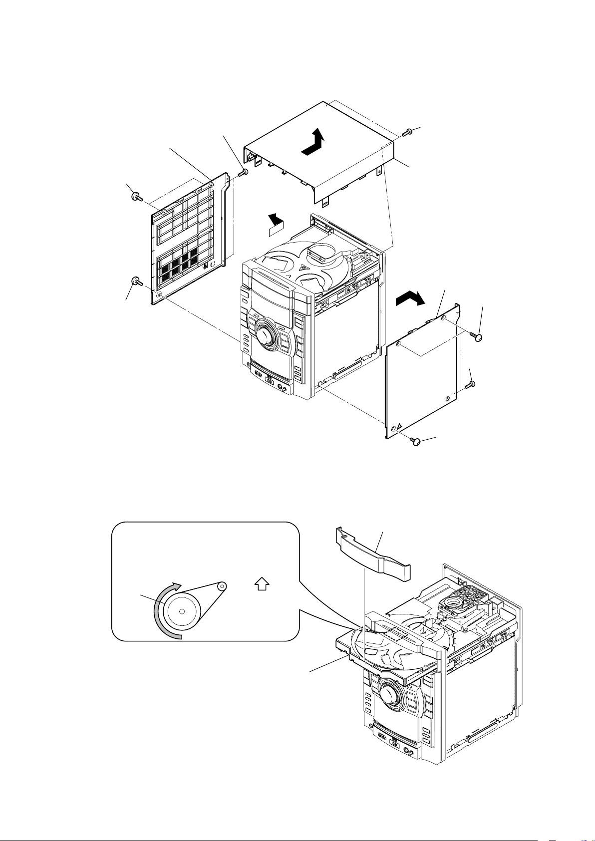
2-1. CASE (TOP)
two screws
(+BVTP 3 x 10)
panel (side-L)
two
screws
(case 3 TP2)
screw
(case 3 TP2)
RT
HCD-GTX777/GTX787/GTX888
RB
two screws
(+BVTP 3 x 10)
RE
case (top)
panel (side-R)
two
screws
(case 3 TP2)
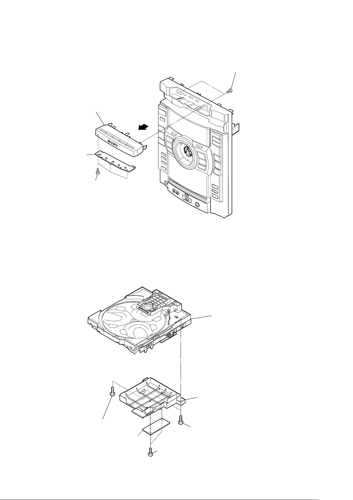
2-2. LOADING PANEL
CD mechanism deck (CDM74KF)
Turn the pulley to the direction of the arrow.
pulley
Front panel side
loading panel
two screws
(+BVTP 3 x 10)
screw
(case 3 TP2)
Pull-out the disc tray.
13
HCD-GTX777/GTX787/GTX888
Ver. 1.1
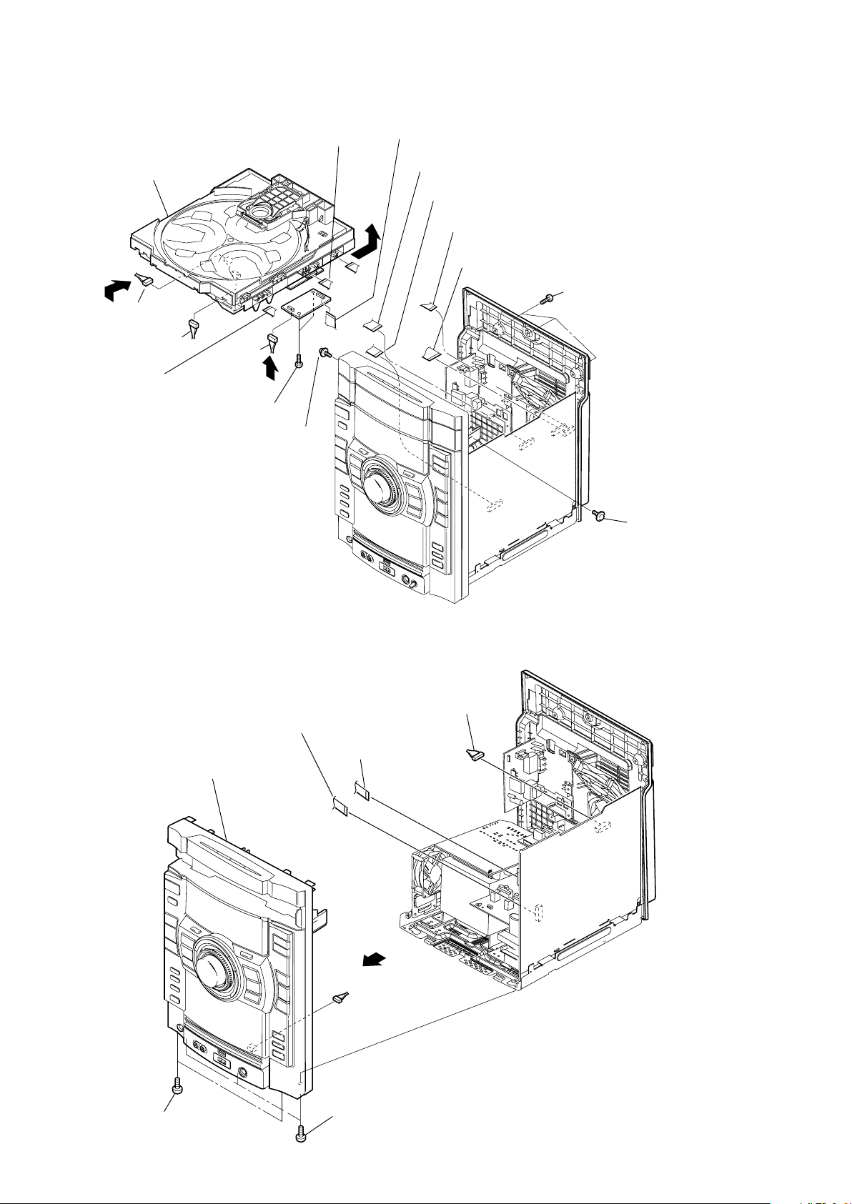
2-3. CD BLOCK SECTION
wire (flat type) (13 core)
(CN701)
RB
CD block section
CN901 (2P)
CN903 (5P)
RT
Wire (flat type) (21 core)
(CN907)
RE
CN400
(8p)
RG
two screws
(+BVTP 3
a
x 10)
tapping screw
wire (flat type) (11 core)
(CN410 )
wire (flat type) (13 core)
(CN110)
RH
wire (flat type) (11 core)
(CN102)
wire (flat type) (31 core)
(CN430)
wire (flat type) (21 core)
a
c
(CN204)
screws
three
(+BVTP 3
c
a
b
x 12)
c
b
b
d
d
2-4. FRONT PANEL SECTION
front panel section
wire (flat type) (7 core)
(CN115)
wire (flat type) (25 core)
(CN114)
CN101 (7P)
d
tapping screw
14
two screws
(+BVTP 3 x 10)
screws
three
(+BVTP 3 x 10)
HCD-GTX777/GTX787/GTX888
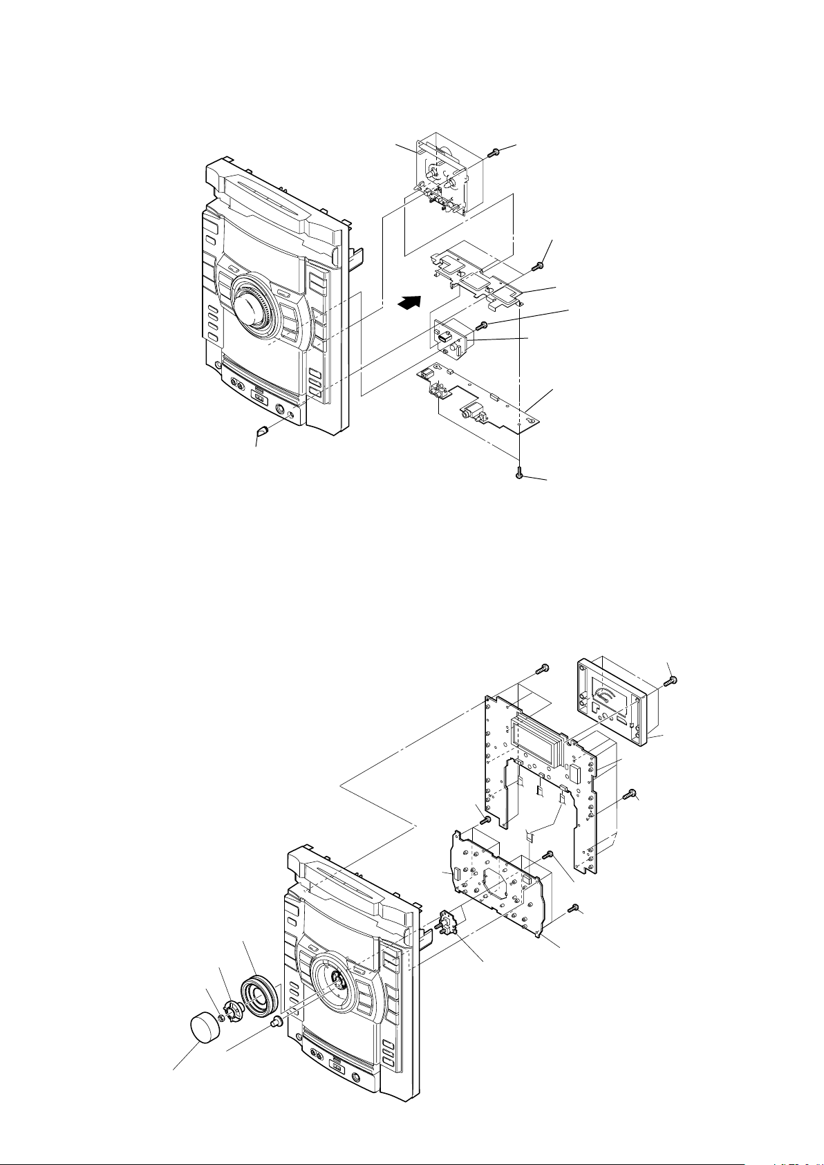
2-5. TAPE MECHANISM DECK, MIC BOARD, USB CONNECTOR BOARD
tape mechanism deck
four screws
(+BVTP 2.6 (3CR))
three screws
(+BVTP 2.6 (3CR))
knob (MIC)
2-6. PANEL BOARD, FUNCTION BOARD, JOG BOARD
bracket (MIC shield)
(+BVTP 2.6 (3CR))
USB CONNECTOR board
MIC board
two
(+BVTP 2.6 (3CR))
six screws
(+BVTP 2.6 (3CR))
three screws
screws
four
(+BVTP 2.6 (3CR))
screws
RE
knob jog assy
RT
holder (jog)
RB
nut
knob (volume)
RG
gear (encoder)
four screws
(+BVTP 2.6 (3CR))
b
RH
JOG board
meter display assy
panel board
b
a
two screws
(+BVTP 2.6 (3CR))
four screws
(+BVTP 2.6 (3CR))
illumination board
six screws
(+BVTP 2.6 (3CR))
15
HCD-GTX777/GTX787/GTX888
Ver. 1.1
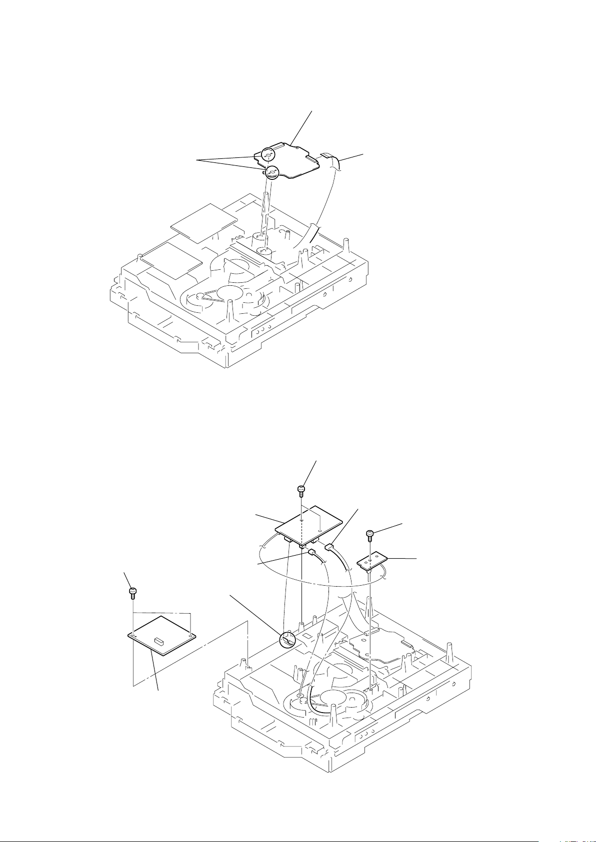
2-7. CD-SW BOARD
escucheon (CD)
CD-SW board
three
(+BVTP 2.6 (3CR))
screws
screws
two
(+BVTP 2.6 (3CR))
2-8. COVER (CDM), TC BOARD
one screw
(+BVTP 3
TC board
CD mechanism deck
cover (CDM)
s
10)
two screws
(+BVTP 3
s
10)
16
two screw
(+BVTP 2.6 (3CR))
2-9. TUNER PACK
tuner pack
HCD-GTX777/GTX787/GTX888
Ver. 1.1
wire (flat type) (9 core)
(CN1)
two
screws
(+BVTP 3 x 8)
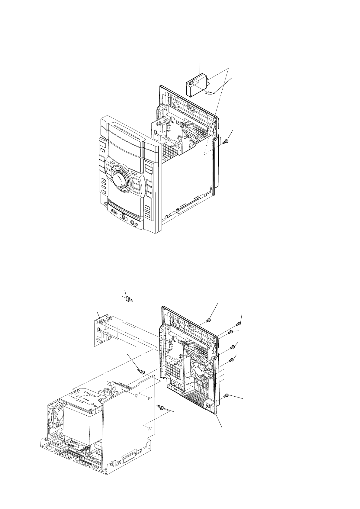
2-10. BACK PANEL SECTION, SUB TRANS BOARD
CN1203 (4P)
sub trans board
CN206 (3P)
CN202 (3P)
two screws
(+BVTP 3
(+BVTP 3 s10)
(+BVTP 3 s10)
two screws
three screws
(+BVTP 3 s10)
RB
back panel section
s
10)
one
screw (GTX888 only)
one
screw (GTX888 only)
one screw
two screws
three screws
(+BVTP 3 s10)
(+BVTP 3 s10)
(+BVTP 3 s10)
(+BVTP 3 s10)
(GTX787)
(GTX777/GTX888)
(GTX777/GTX787)
(GTX888)
17
HCD-GTX777/GTX787/GTX888
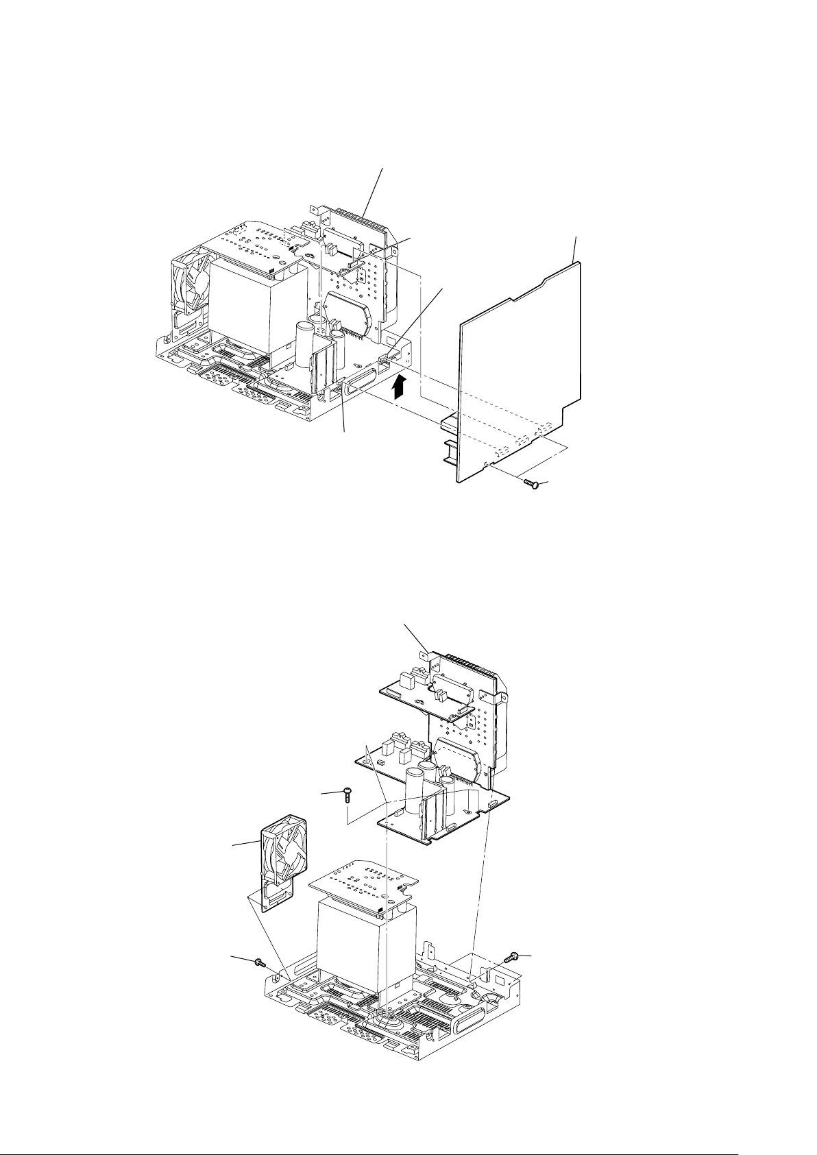
2-11. MAIN BOARD
POWER board assy
CN809 (9 pin)
CN610
(8 pin)
MAIN board
CN611
(8 pin)
2-12. POWER BOARD SECTION, DC FAN (FOR GTX888)
POWER board section
four screws
(+BV3 (3-CR))
two screws
(+BV3 (3-CR))
18
DC fan (M893)
TX
(For G
two screws
(+BVTP 3 × 10)
888 Only)
three screws
(+BVTP 3 ×10)
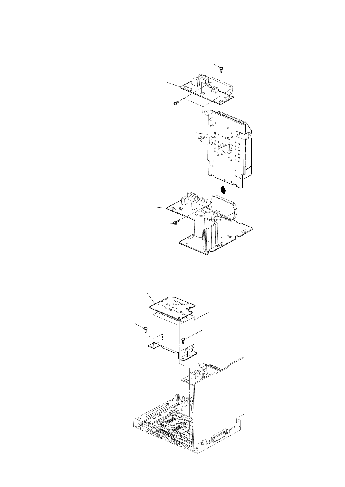
2-13. SUBWOOFER BOARD, POWER BOARD
SUBWOOFER board
two screws
(transistor)
(+BV3 (3-CR))
heat sink assy
HCD-GTX777/GTX787/GTX888
two screws
POWER board
(transistor)
2-14. POWER TRANSFORMER (T1200)
TRANS board
three
(+BVTT 4 x 8)
screws
two screws
power transfomer (T1200)
three
(+BVTT 4 x 8)
screws
19
HCD-GTX777/GTX787/GTX888
Ver. 1.1
2-15. BD93 BOARD
Remove the four solders.
BD93
board
wire (flat type) (16 core)
(CN301)
2-16. DRIVER BOARD, SW BOARD, USB R BOARD
DRIVER board
two screws
(+BVTP2.6 (3CR))
USB board
CN704 (2P)
wire (flat type) (5 core)
(CN702)
two screws
(+BVTT (M2.6))
CN703 (4P)
screw
(+BVTT (M2.6))
SW board
20
2-17. OPTICAL PICK-UP
optical pick-up
(BU-K6BD93UR)
two insulators
two coil springs
(insulator)
HCD-GTX777/GTX787/GTX888
two insulators
two coil springs
(insulator)
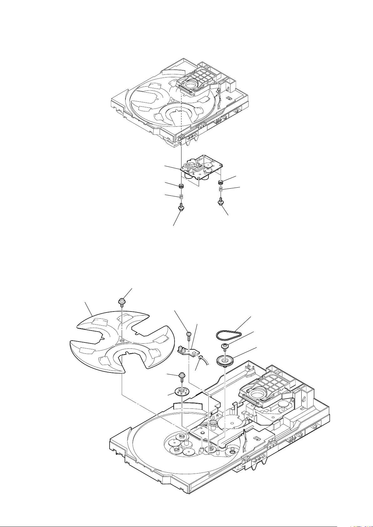
2-18. SENSOR BOARD
t
ray
floating
(+PTPWH M2.6)
floating
(+PTPWH M2.6)
g
screw
(+BTTP (M2.6))
screw
ear (geneva)
one screw
two floating screws
(+PTPWH M2.6)
SENSOR board
CN731
(3P)
two floating screws
(+PTPWH M2.6)
b
elt (table)
floating
(+PTPWH M2.6)
p
ulley (table)
screw
21
HCD-GTX777/GTX787/GTX888
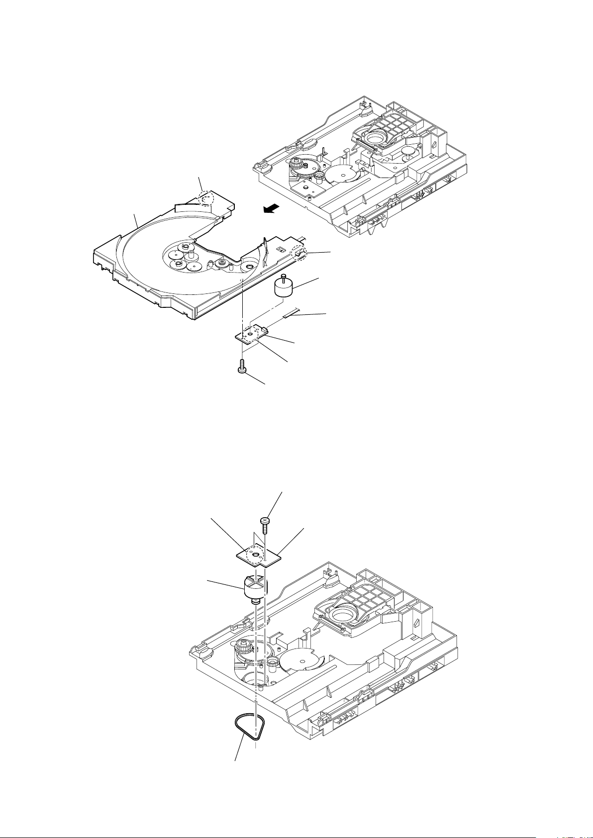
2-19. MOTOR (TB) BOARD
stopper
table
2-20. MOTOR (LD) BOARD
Remove the two solderings of motor.
Remove the two solderings of motor.
two screws
(+BTTP (M2.6))
two screws
(+BTTP (M2.6))
stopper
t
able motor assy (M741)
wire (flat type) (5 core)
(CN742)
MOTOR (TB) board
MOTOR (LD) board
22
l
oading motor assy (M751)
b
elt (loading)

SECTION 3
TEST MODE
HCD-GTX777/GTX787/GTX888
[GC TEST MODE]
• This mode is used to check the fl uorescent indicator tube, LEDs,
buttons, MASTER VOLUME knob, OPERATION DIAL knob,
model, destination, software version.
Procedure:
1. Press x button, [DELAY] button and [DISC 2] button
simultaneously.
2. All LEDs and segments in fl uorescent indicator tube are lighted
up.
All LEDs are lighted up in red color except for
the LED is lighted up in red and blue color.
3. When you want to enter to the model version and destination
display mode, press [DISC 1] button. The model information
appears on the fl uorescent indicator tube.
4. Each time [DISC 1] button is pressed, the display changes to
display software version and date of the software creation. The
sequence is SC version, GC version, SYS version, CD version,
CDDM version, CDMA version, CDMB version, BDA version,
BDB version, ST version, TC version, TA version, TM version,
MM1 version, MM2 version and MTR version in this order, and
returns to the model version display.
5. Press [DISC 2] button, the key check mode is activated.
6. In the key check mode, the fl uorescent indicator tube displays
“K 0 J0 V0”.
Turn the [OPERATIONAL DIAL] clockwise; “J” value increases
by one. Turn the [OPERATIONAL DIAL] counterclockwise; “J”
value decreases by one. Each time a button is pressed, “K” value
increases. Press other keys on main unit to check whether the
key is detected. However, once a button has been pressed, it is
no longer taken into account.
“V” value increases in the manner of 0, 1, 2, 3 ... if [MASTER
VOLUME] knob is turned clockwise, or it decreases in the manner
of 0, 9, 8, 7 ... if [MASTER VOLUME] knob is turned
counterclockwise.
7. When [DISC SKIP/EX-CHANGE] button is pressed after all LEDs
and segments in fl uorescent indicator tube light up, alternate
segments in fl uorescent indicator tube and LED would light up.
If you press [DISC SKIP/EX-CHANGE] button again, another half
of alternate segments in fl uorescent indicator tube and LEDs
would light up. Press [DISC SKIP/EX-CHANGE] button would
cause all segments in fl uorescent indicator tube and LED turns
off. Pressing [DISC SKIP/EX-CHANGE] button again would cause
all LED and segments lights up.
8. To release from this mode, press three buttons in the same man-
ner as step 1, or disconnect the power cord.
LED where
[MC TEST MODE]
• This mode is used to check operations of the respective sections
of Amplifi er, Tuner and Tape.
Procedure:
• To enter MC Test Mode
1. Press x button, [DELAY] button and [DISC 3] button
simultaneously.
2. The CD ring indicators fl ash on the fl uorescent indicator tube.
The function is changed to VIDEO.
* Check of Amplifi er
1. Press [EQ BAND/MEMORY] button repeatedly until a message
“GEQ MAX” appears on the fl uorescent indicator tube. GEQ
increases to its maximum.
2. Press [EQ BAND/MEMORY] button repeatedly until a message
“GEQ MIN” appears on the fl uorescent indicator tube. GEQ
decreases to its minimum.
3. Press [EQ BAND/MEMORY] button repeatedly until a message
“GEQ FLAT” appears on the fl uorescent indicator tube. GEQ
is set to fl at.
4. When the [MASTER VOLUME] knob is turned clockwise even
slightly, the sound volume increases to its maximum and a message “VOLUME MAX” appears on the fl uorescent indicator
tube.
5. When the [MASTER VOLUME] knob is turned counter-clockwise
even slightly, the sound volume decreases to its minimum and a
message “VOLUME MIN” appears on the fl uorescent indicator
tube.
* Tape function
1. Insert a tape in deck. The function is changed to VIDEO au-
tomatically when the recording is started by pressing [REC TO
TAPE] then press [ENTER] button.
2. During recording, press m button will stop the recording and
the function is changed to TAPE and rewind the tape in Deck
until the recording start position and playback of the tape in
Deck is started.
* To release from MC Test mode
1. To release from this mode, press ?/1 button.
2. The cold reset is enforced at the same time.
[COLD RESET]
• The cold reset clears all data including preset data stored in the
RAM to initial conditions. Execute this mode when returning the
set to the customer.
Procedure:
1. Press x button, [DELAY] button and ?/1 button
simultaneously.
2. The fl uorescent indicator tube becomes blank for while, and the
set is reset.
[VACS ON/OFF]
• This mode is used to switch ON and OFF the VACS (Variable
Attenuation Control System).
Procedure:
1. Press ?/1 button to turn on the system.
2. Press x button and [OPTIONS] button simultaneously. The
message “VACS OFF” or “VACS ON” appears on the fl uorescent
indicator tube.
[TUNER STEP CHANGE]
• The step interval of AM channels can be toggled between 9 kHz
and 10 kHz.
Procedure:
1. Press ?/1 button to turn on the system.
2. Press [TUNER/BAND] button to select the “AM”.
3. Press ?/1 button to turn off the system.
4. Press [ENTER] button and ?/1 button simultaneously. The
system will turn on automatically. The message “AM 9K STEP”
or “AM 10K STEP” appears on the fl uorescent indicator tube
and thus the channel step is changed.
23
HCD-GTX777/GTX787/GTX888
[CD SERVICE MODE]
• This mode let you move the CD sled motor freely. Use this mode
when you want to clean the optical pick-up.
Procedure:
1. Press ?/1 button to turn on the system.
2. Select CD function.
3. Press x button, [DELAY] button and [OPEN/CLOSE] button
simultaneously.
4. The CD service mode is activated. The message “SERVICE
MODE” appears on the fl uorescent indicator tube.
5. With the CD in stop status, press M to move the optical pick-
up to outside track, or turn m to move to inside track. The
message “SLED OUT” or “SLED IN” appears on the fl uorescent
indicator tube.
6. To turn on or off the laser, press > button. The message “LD
ON” or “LD OFF” appears on the fl uorescent indicator tube.
7. To release from this mode, press ?/1 button to turn off the
system.
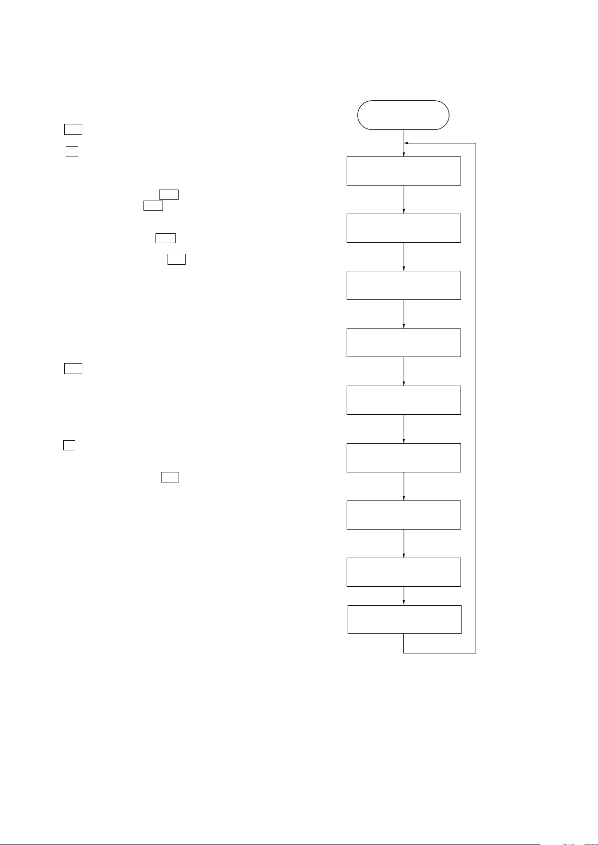
[CD AGING MODE]
• This mode can be used for operation check of CD section. If
an error occurs, the aging operation would stops and the status
is displayed. If there were no error occurs, the aging operation
would continue repeatedly.
Procedure:
1. Press ?/1 button to turn on the system.
2. Select CD function.
3. Load three discs on disc tray.
4. Press [PLAY MODE/TUNING MODE] button on the remote con-
trol repeatedly to select the “ALL DISCS” mode, and press the
[REPEAT/FM MODE] button on the remode control repeatedly
to select repeat mode off.
5. Press x button, [DELAY] button and [DISC SKIP/EX-CHANGE]
button simultaneously.
6. Aging operation is started.
7. To release from this mode, press ?/1 button or disconnect the
power cord to turn the power OFF.
• Aging mode sequence:
START
DISC CHUCKING
TOC READING
PLAY FIRST TRACK FOR 2
SECONDS
PLAY LAST TRACK FOR 2
SECONDS
EX-CHANGE OPEN/CLOSE
OPEN THE DISC TRAY
DISC SKIP
CLOSE THE DISC TRAY
CHANGE THE NEXT DISC
24
HCD-GTX777/GTX787/GTX888
[CD ERROR CODE MODE]
• Display the CD error code when an error occurred.
Procedure:
1. Press x button, [DELAY] button and [DISC 1] button
simultaneously to enter the error code display mode.
2. The fl uorescent indicator tube display the number of total error.
3. Each time m button and M button are turned, display
change as below.
DISPLAY OF
TOTAL ERROR
.N
.
.
BUTTON
DISPLAY OF
MECHANICAL
ERRORS
.N
BUTTON
DISPLAY OF
NO DISC
ERRORS
BUTTON
.
BUTTON
.
4. To clear the error record, operate the cold reset. (Refer to the
“MC COLD RESET”.)
5. To release from this mode, press the ?/1 button or disconnect
the power plug to turn the power OFF.
• Display of total error
Em**Ed**
Em** : The number of times for CDM (mechanical) errors.
Ed** : The number of times for BD error (after chucking the
disc.).
• Display of CDM (mechanical) error. It is show with “M” and
11 digit number.
M*$$%%&&0–
000
M* : The number of history error for mechanical. (“0” is
latest one) (Turn > button to display next error.)
$$ : Mechanical errors occur in the operation.
FF : Mechanical error during normal operation.
Other : Mechanical error during initializing operation.
%% : The process when trouble occurs
01 : Process ejecting DISC
02 : Process waiting for inserting DISC
03 : Process sending request to insert a disc to upper
layer.
04 : Process sending request to eject a disc to upper
layer.
05 : Process pulling a DISC in.
06 : Chucking process
07 : Re-chucking process
08 : Process cancelling chucking
&& : The operation when trouble occurs
00 : Waiting for operation.
10/11/12/13: During eject operation
20 : While pulling a disc in
30 : While cancelling chucking
40/41/42/43: During eject operation due to error.
0000 : Not used (Value is fi xed to 0000).
• Display of BD error. It is shown with “D” and 11 digits
number.
D*$$%%&&#–
#00
D* : The number of error history (“0” is latest one)
(Press > button to display next error.)
$$ : The detail of trouble
01 : Can not focus
02 : GFS error
03 : Start-up time over
04 : Continuously out of focus
05 : Q code is not input for certain time
06 : Tracking on is impossible
07 : Blank disc
%% : The process when trouble occurs
01 : While SHIP process is performed
02 : While POWER OFF is processed
03 : While INITIALIZE (POWER ON) is processed.
04 : While oscillation stops
05 : From stopping oscillation to start oscillation
06 : During stop
07 : During STOP operation
08 : While start-up is processed
09 : While TOC reading is processed
0a : During search operation
0b : During PLAY operation
0c : During pause operation
0d : During PLAY manual search operation
0e : During PAUSE manual search operation
&& : Processing operation when trouble occurs
Show each STEP mentioned in %% digits.
## : Disc speed when trouble occurs.
01 : x1 speed
02 : x2 speed (for models which support x2 speed)
04 : x4 speed
00 : Not used (value is fi xed to 00).
25

HCD-GTX777/GTX787/GTX888
[CD REPEAT 5 LIMIT OFF MODE]
• The number of repeat for CD playback is 5 times when the repeat mode is “REPEAT ALL”. This mode enables CD to repeat
playback for limitless times.
Procedure:
1. Press ?/1 button to turn on the system.
2. Select CD function.
3. Press [EQ BAND/MEMORY] button, [CD] button and [DISC 1]
button simultaneously to enter the CD repeat 5 limit off mode
and the fl uorescent indicator tube displays “LIMIT OFF”.
• To release from this mode, operate the cold reset.
(Refer to the “MC COLD RESET”.)
[CD SHIP MODE (WITH MEMORY CLEAR)]
• This mode moves the optical pick-up to the position durable to
vibration and clears all data including preset data stored in the
RAM to initial conditions. Use this mode when returning the set
to the customer after repair.
Procedure:
1. Press ?/1 button to turn on the system.
2. Select CD function.
3. Press x button, [SOUND FLASH] button and ?/1 button
simultaneously. The system will turn off automatically.
4. After the “STANDBY” blinking display fi nishes, a message
“MECHA LOCK” is displayed on the fl uorescent indicator tube
and the CD ship mode is set.
5. The Memory is clear after AC Power OFF.
[CD SHIP MODE (WITHOUT MEMORY CLEAR)]
• This mode moves the optical pick-up to the position durable to
vibration. Use this mode when returning the set to the customer
after repair.
Procedure:
1. Press ?/1 button to turn on the system.
2. Select CD function.
3. Press [CD] button and ?/1 button simultaneously. The system
will turn off automatically.
4. After the “STANDBY” blinking display fi nishes, a message
“MECHA LOCK” is displayed on the fl uorescent indicator tube
and the CD ship mode is set.
[CD TRAY LOCK MODE]
• This mode let you lock the disc tray. When this mode is activated,
the disc tray will not open when [OPEN/CLOSE] button or [DISC
SKIP/EX-CHANGE] button is pressed. The message “LOCKED”
will be displayed on the fl uorescent indicator tube.
Procedure:
1. Press ?/1 button to turn on the system.
2. Select CD function.
3. Press x button, [OPEN/CLOSE] button simultaneously and
hold down until “LOCKED” or “UNLOCKED” displayed on
the fl uorescent indicator tube (around 5 seconds).
[TCM OFFLINE MODE]
• This mode is used to prevent the system from turning off automatically when TCM is not connected. Therefore, measurements can
be done even when TCM is not connected during production.
Procedure:
1. When the system is turned off, press [EQ BAND/MEMORY]
button, [TAPE] button and ?/1 button simultaneously. The
system will turn on automatically.
2. The message “TCM OFFLINE” will be displayed on the fl uo-
rescent indicator tube.
[VACS DISPLAY]
• This mode is used to check the VACS level.
Procedure:
1. Press ?/1 button to turn on the system.
2. Press x button, [CHORUS] button and [DISC SKIP/EX-
CHANGE] button simultaneously.
3. The VACS Level Display, the fl uorescent indicator tube displays
“VATB F APC”. “V” represent VACS, A represent VACS level
which is triggered by signal level, “T” represent Thermal VACS
NEO, B represent VACS level which is triggered by temperature,
“F” represent FAN is triggered by software to turn in to high
speed, “AP” represent APVACS (Abuse Protection VACS) and
“C” represent APVACS level which is triggered.
26
HCD-GTX777/GTX787/GTX888
[METER SWITCH TOUCH COUNT DISPLAY]
• This mode is used to display the total count of meter pointer
touch initial switch and max switch.
Procedure:
1. Press
button to turn on the system.
2. Press x button, [ENTER] button and [DISPLAY] button
simultaneously.
3. The fl uorescent indicator tube displays “IxxxxxMyyyyy”.
“I” represents the Initial Switch touch.
“xxxxx” represents the total count of Initial Switch touch.
(Maximum Value of “xxxxx” = 65535)
“M” represents the Max Switch touch.
“yyyyy” represents the total count of Max Switch touch.
(Maximum Value of “yyyyy” = 65535)
4 To release from this mode, do step (2) again.
The fl uorescent indicator tube displays “MODE OUT”.
[METER TEST MODE]
• This mode is used to check the meter device.
Procedure:
1. Press button to turn on the system.
2. Press x button, [ENTER] button and [METER MODE] button
simultaneously.
3. Meter Backlight LEDs, Meter Pointer LEDs, Power Illuminator
LEDs and fl uorescent indicator tube are lighted up.
4. When you want to perform count total step from Initial Switch
to Max Switch operation mode, press [>>] button. The meter
pointer will move from Initial Switch to Max Switch and fi nally
move back to the middle position. The total step count information appears on the fl uorescent indicator tube. “xxx STP yy” is
shown.
“xxx” represents the total step.
(Value of “xxx” should between 430 steps to 470 steps)
“yy” represents the status of total step count.
(If total step between 430 steps to 470 steps, “yy” is OK,
else “yy” is NG)
5. When you want to perform count total step from Max Switch
to Initial Switch operation mode, press [<<] button. The meter
pointer will move from Max Switch to Initial Switch and fi nally
move back to the middle position. The total step count information appears on the fl uorescent indicator tube. “xxx STP yy” is
shown.
“xxx” represents the total step.
(Value of “xxx” should between 430 steps to 470 steps)
“yy” represents the status of total step count.
(If total step between 430 steps to 470 steps, “yy” is OK,
else “yy” is NG)
6 To release from this mode, do step (2) again.
The fl uorescent indicator tube displays “TST MODE OUT”.
SECTION 4
MECHANICAL ADJUSTMENTS
Precaution
1. Clean the following parts with a denatured alcohol-moistened
swab:
record/playback heads pinch rollers
erase head rubber belts
capstan idlers
2. Demagnetize the record/playback head with a head demagnetizer.
3. Do not use a magnetized screwdriver for the adjustments.
4. After the adjustments, apply suitable locking compound to the
parts adjusted.
5. The adjustments should be performed with the rated power
supply voltage unless otherwise noted.
Torque Measurement
Mode Torque meter Meter reading
2.9m N • m to 6.9m N • m
FWD CQ-102C 30 to 70 g • cm
(0.42 – 0.97 oz • inch)
FWD 0.15m N • m to 0.59m N • m
back tension CQ-102C 2 to 6 g • cm
(0.03 – 0.08 oz • inch)
2.9m N • m to 6.9m N • m
REV CQ-102RC 30 to 70 g • cm
(0.42 – 0.97 oz • inch)
0.15m N • m to 0.59m N • m
REV
CQ-102RC 2 to 6 g • cm
back tension
4.8m N • m to 16.7m N • m
FF/REW CQ-201B 49 to 170 g • cm
(0.68 – 2.36 oz • inch)
(0.03 – 0.08 oz • inch)
27
HCD-GTX777/GTX787/GTX888
ELECTRICAL ADJUSTMENTS
SECTION 5
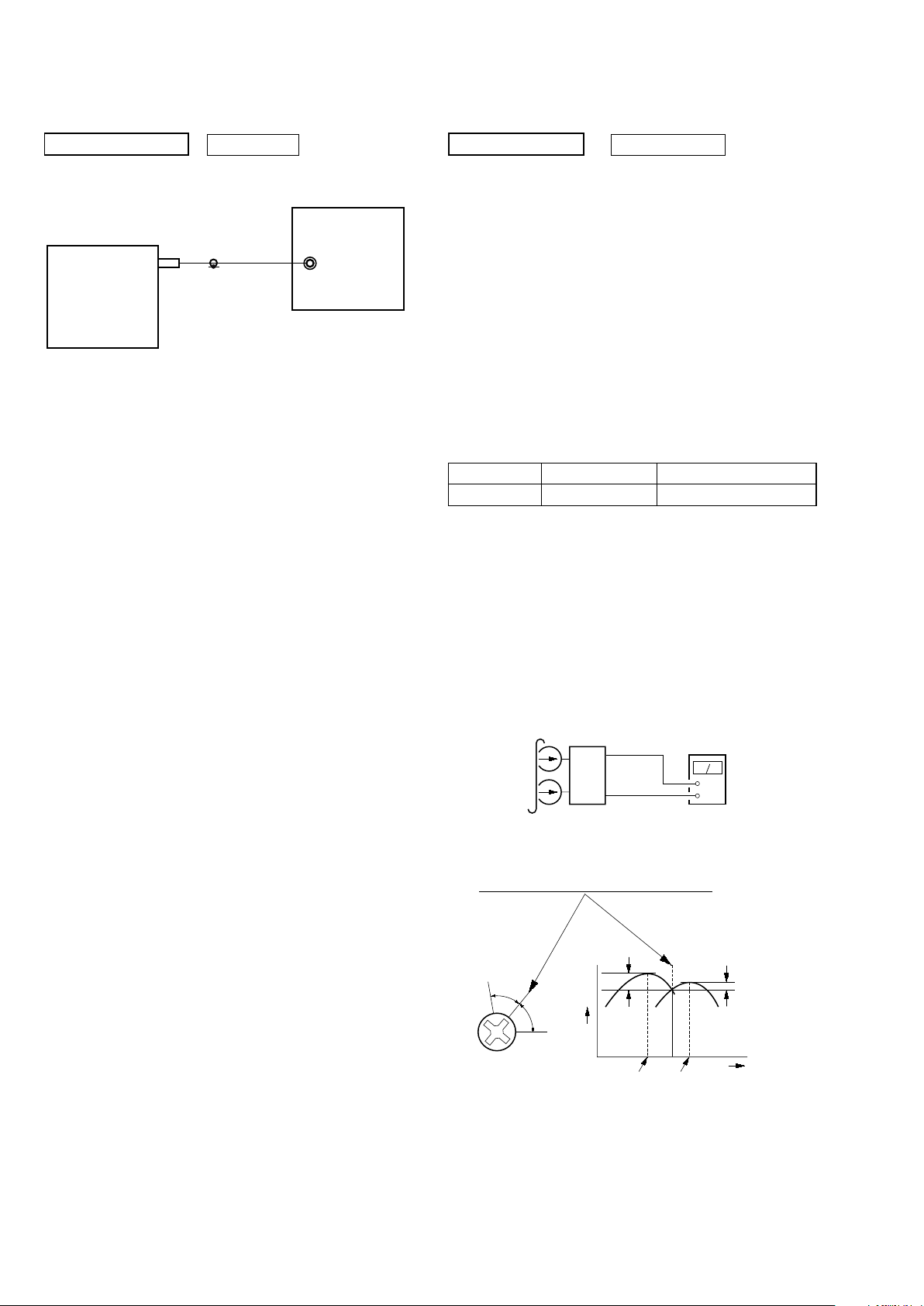
TUNER SECTION 0 dB = 1 µV
[FM Tune Level Check]
FM signal generator
SET
Procedure:
1. Turn the power on.
2. Input the following signal from Signal Generator to FM antenna input directly.
* Carrier Freq : A = 87.5 MHz, B = 98 MHz, C = 108 MHz
Deviation : 75 kHz
Modulation : 1 kHz
ANT input : 35 dBu (EMF)
Note: Please use 75 ohm “coaxial cable” to connect SG and the set. You
cannot use video cable for checking.
Please use SG whose output impedance is 75 ohm.
3. Set to FM tuner function and tune A, B and C signals.
4. Confi rm “TUNED” is lit on the display for A, B and C signals.
The mark of “TUNED” means “The selected station signal is received in good condition.”
OUT (75 7)
DECK SECTION 0 dB = 0.775 V
1. Demagnetize the record/playback head with a head
demagnetizer.
2. Do not use a magnetized screwdriver for the adjustments.
3. After the adjustments, apply suitable locking compound to the
parts adjust.
4. The adjustments should be performed with the rated power
supply voltage unless otherwise noted.
5. The adjustments should be performed in the order given in this
service manual. (As a general rule, playback circuit adjustment should be completed before performing recording circuit
adjustment.)
6. The adjustments should be performed for both L-CH and RCH.
7. Switches and controls should be set as follows unless otherwise
specifi ed.
• Test Tape
Tape Signal Used for
P-4-A100 10 kHz, –10 dB Azimuth Adjustment
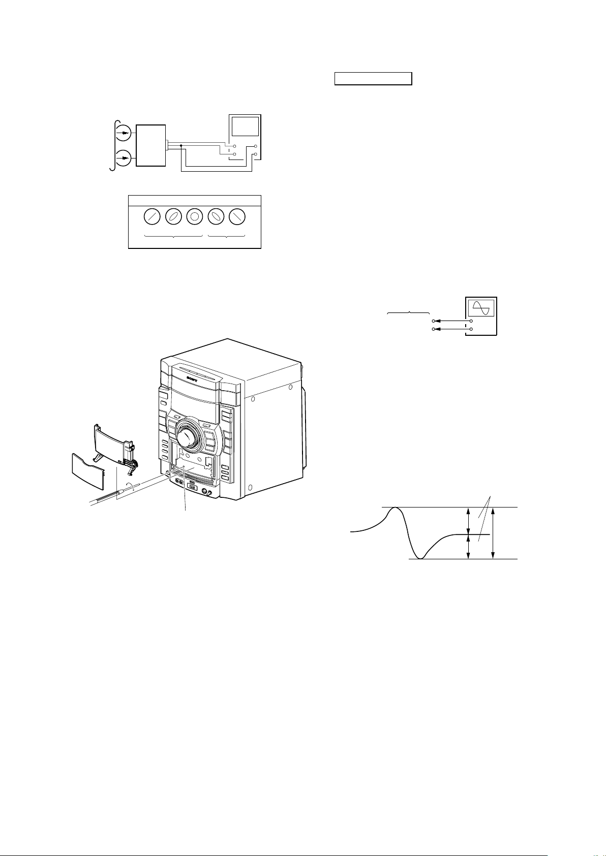
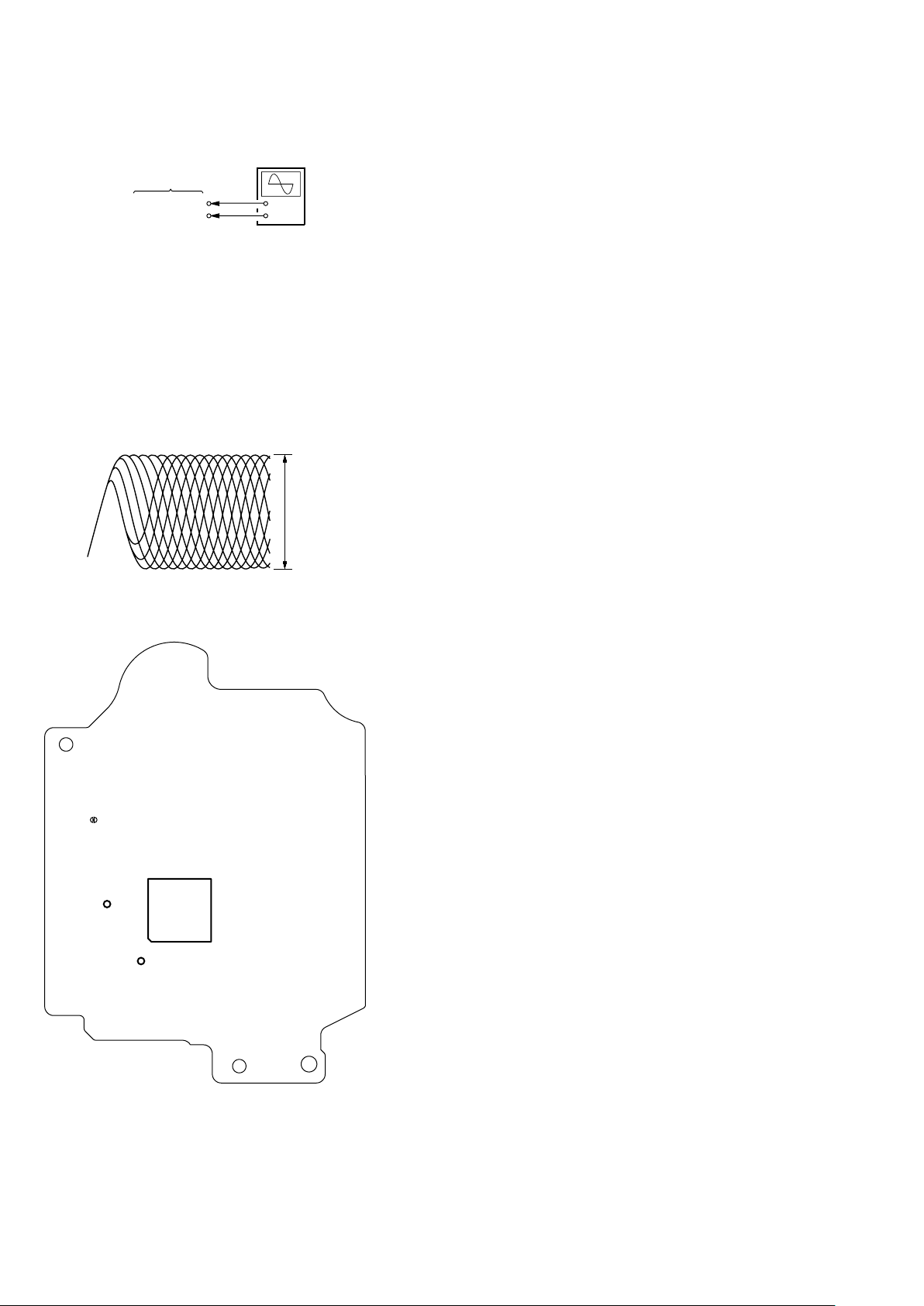
[RECORD/PLAYBACK HEAD AZIMUTH
ADJUST-MENT]
Note: Perform this adjustments for Single deck
Procedure:
1. Mode: Playback
test tape
P-4-A100
(10 kHz, –10 dB)
(L-CH & R-CH)
set
level meter
+
–
2. Turn the adjustment screw and check output peaks. If the peaks
do not match for L-CH and R-CH, turn the adjustment screw
so that outputs match within 1dB of peak.
output
level
within
1dB
L-CH
peak
R-CH
peak
within
1dB
screw
position
L-CH
peak
screw
position
R-CH
peak
28
HCD-GTX777/GTX787/GTX888
3. Mode: Playback
test tape
P-4-A100
(10 kHz, –10 dB)
L-CH
R-CH
waveform of oscilloscope
in phase
L
R
45o 90 o 135o 180 o
good
oscilloscope
V
wrong
H
4. After the adjustments, apply suitable locking compound to
the parts adjusted.
Adjustment Location: Playback Head (Deck).
CD SECTION
[TEST DISC LIST]
Use the following test disc on test mode.
• CD: YEDS-18 (PART No. 3-702-101-01)
or
PATD-012 (PART No. 4-225-203-01)
Note:
1. CD Block is basically designed to operate without adjustment.
Therefore, check each item in order given.
2. Use YEDS-18 (3-702-101-01) unless otherwise indicated.
3. Use an oscilloscope with more than 10MW impedance.
4. Clean the object lens by an applicator with neutral detergent
when the signal level is low than specifi ed value with the
following checks.
[S-CURVE CHECK]
oscilloscope
BD93 board
TP106(FE)
TP124(VC)
Procedure :
1. Connect an oscilloscope to TP106 (FE) and TP124 (VC).
2. Turn the power on.
3. Load a disc (YEDS-18) and actuate the focus search. (In
consequence of open and close the disc tray, actuate the focus
search)
4. Confi rm that the oscilloscope waveform (S-curve) is symmetrical
between A and B and confi rm peak to peak level within 3 ± 0.5
Vp-p.
+
–
forwa rd
S-curve waveform
symmetry
A
within 3
B
±
0.5Vp-p
Note: • Try to measure several times to make sure that the ratio
of A : B or B : A is more than 10 : 7.
• Take sweep time as long as possible and light up the
brightness to obtain best waveform.
29
HCD-GTX777/GTX787/GTX888
[RF LEVEL CHECK]
oscilloscope
BD93 board
TP123(RFO)
TP124(VC)
Procedure :
1. Connect an oscilloscope to TP123 (RFO) and TP124 (VC).
2. Turn the power on.
3. Load a disc (YEDS-18) and playback.
4. Confi rm that oscilloscope waveform is clear and check if RF
signal level is correct or not.
Note: Clear RF signal waveform means that the shape “ ◊ ” can
be clearly distinguished at the center of the waveform.
+
–
RF signal waveform
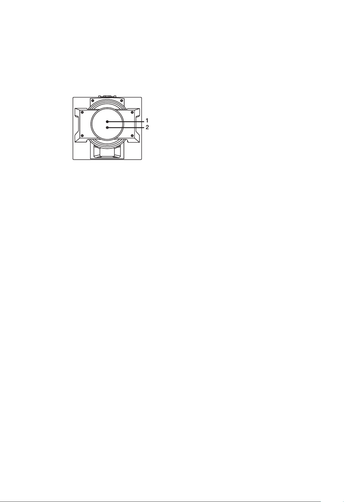
Connecting Location: CD board
– BD93 Board (SIDE B) –
TP124
(VC)
(FE)
IC101
25
51
50
26
TP123
(RFO)
75
76
100
1
TP106
VOLT/DIV: 200 mV
TIME/DIV: 500 ns
level: 1.3
±
0.3 Vp-p
30
 Loading...