

Sony HCD-GPZ6, HCD-GPZ7 Service Manual
HCD-GPZ6/GPZ7
SERVICE MANUAL
Ver. 1.0 2005.03
• HCD-GPZ6 is the amplifier, CD player, tape
deck and tuner section in CMT-GPZ6.
• HCD-GPZ7 is the amplifier, CD player, tape
deck and tuner section in CMT-GPZ7.
US and foreign patents licensed from Dolby
Laboratories.
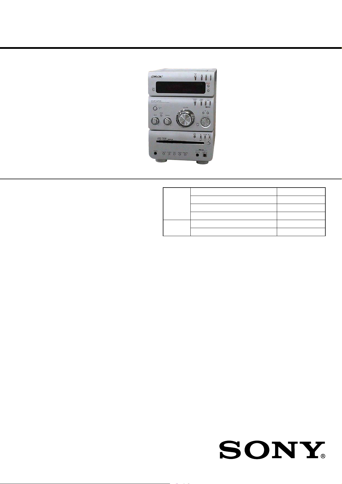
Photo: HCD-GPZ6
CD
Section
Tape deck
Section
AEP Model
HCD-GPZ7
UK Model
HCD-GPZ6
Model Name Using Similar Mechanism NEW
CD Mechanism Type CDM80B-F1BD83
Base Unit Name BU-F1BD83
Optical Pick-up Block Name KSM-215DCP/C2NP
Model Name Using Similar Mechanism NEW
Tape T ransport Mechanism T ype CMAL5Z232A
Amplifier section
HCD-GPZ7
DIN power output (rated): 40 + 40 W (6 ohms at
1kHz, DIN)
Continuous RMS power output (reference):
60 + 60 W (6 ohms at
1kHz, 10% THD)
Music power output (reference):
100 + 100 W (6 ohms at
1kHz, 10% THD)
HCD-GPZ6
DIN power output (rated): 40 + 40 W (6 ohms at
1kHz, DIN)
Continuous RMS power output (reference):
50 + 50 W (6 ohms at
1kHz, 10% THD)
Music power output (reference):
90 + 90 W (6 ohms at
1kHz, 10% THD)
Inputs
ANALOG IN (stereo mini jack):
Sensitivity 250 mV,
impedance 47 kilohms
Outputs
CD DIGITAL OUT:
Optical Wavelength:
660 nm
PHONES (stereo mini jack):
accepts headphones with
an impedance of 8 ohms or
more
SPECIFICATIONS
SPEAKER: accepts impedance of 6 to
16 ohms
CD player section
System Compact disc and digital
audio system
Laser Diode Properties Emission duration:
continuous
Laser Output*:
Less than 44.6 µW
*This output is the value measurement at a distance of
200 mm from the objective lens surface on the
Optical Pick-up Block with 7 mm aperture.
Frequency response 20 Hz − 20 kHz (±0.5 dB)
Wav elength 780 − 790 nm
Tape deck section
Recording system 4-track 2-channel stereo
Frequency response 50 − 13,000 Hz (±3 dB),
using Sony TYPE I
cassettes
Tuner section
FM stereo, FM/AM superheterodyne tuner
FM tuner section
Tuning range 87.5 − 108.0 MHz
Aerial FM lead aerial
Aerial terminals 75 ohms unbalanced
Intermediate frequency 10.7 MHz
COMPACT DISC DECK RECEIVER
AM tuner section
Tuning range 531 − 1,602 kHz
Aerial AM loop aerial
Aerial terminals External aerial terminal
Intermediate frequency 450 kHz
General
Power requirements 230 V AC, 50/60 Hz
Power consumption
CMT-GPZ7 100 W
CMT-GPZ6 90 W
Dimensions (w/h/d) (excl. speakers)
Mass (excl. speakers)
Amplifier/Tuner/Tape/CD section:
CMT-GPZ7: 6.1 kg
CMT-GPZ6: 5.8 kg
Design and specifications are subject to change
without notice.
(with the tuning interval
set at 9 kHz)
0.25 W (in Power Saving
Mode)
0.25 W (in Power Saving
Mode)
Approx. 181 × 261 ×
297 mm
9-879-578-01
2005C05-1
© 2005.03
Sony Corporation
Personal Audio Group
Published by Sony Engineering Corporation

HCD-GPZ6/GPZ7
Notes on chip component replacement
• Never reuse a disconnected chip component.
• Notice that the minus side of a tantalum capacitor may be
damaged by heat.
Flexible Circuit Board Repairing
• Keep the temperature of the soldering iron around 270 °C
during repairing.
• Do not touch the soldering iron on the same conductor of the
circuit board (within 3 times).
• Be careful not to apply force on the conductor when soldering
or unsoldering.
CAUTION
Use of controls or adjustments or performance of procedures
other than those specified herein may result in hazardous radiation
exposure.
This appliance is classified as
a CLASS 1 LASER product.
The CLASS 1 LASER
PRODUCT MARKING is
located on the rear exterior.
List of playable discs
Format of discs Disc logo
Audio CDs
CD-R/CD-RW
(audio data, ATRAC3plus
files, MP3 files)
Discs that this system cannot
play
•CD-ROMs
•CD-Rs/CD-RWs other than those recorded in
the following formats:
–music CD format
–ATRAC3plus format and MP3 format that
conform to ISO9660
Joliet or Multi Session
•Discs with non-standard shapes (e.g., heart,
square, star) cannot be played on this unit.
Attempting to do so may damage the unit. Do
not use such discs.
•A disc with paper or stickers on it.
•A disc that has the adhesive, cellophane tape,
or a sticker still left on it.
•An 8 cm disc with an adaptor
1)
ISO9660 Format
The most common international standard for the
logical format of files and folders on a CD-ROM.
There are several specification levels. In Level 1,
file names must be in the 8.3 format (no more than
eight characters in the name, no more than three
characters in the extension) and in capital letters.
Folder names can be no longer than eight characters.
There can be no more than eight nested folder
levels. Level 2 specifications allow file names and
folder names up to 31 characters long. Each folder
can have up to 8 trees.
For Joliet in the expansion format (file and folder
names can have up to 64 characters) make sure of
the contents of the writing software, etc.
2)
Multi Session
This is a recording method that enables adding of
data using the Track-At-Once method.
Conventional CDs begin at a CD control area called
the Lead-in and end at an area called Lead-out. A
Multi Session CD is a CD having multiple sessions,
with each segment from Lead-in to Lead-out
regarded as a single session.
CD-Extra: This format records audio (audio CD
data) on the tracks in session 1 and data on the tracks
in session 2.
Mixed CD: This format records data on the first
track and audio (audio CD data) on the second and
subsequent tracks of a session.
1)
Level 1/Level 2,
2)
SAFETY-RELATED COMPONENT WARNING!!
COMPONENTS IDENTIFIED BY MARK 0 OR DOTTED LINE
WITH MARK 0 ON THE SCHEMATIC DIAGRAMS AND IN
THE PARTS LIST ARE CRITICAL TO SAFE OPERATION.
REPLACE THESE COMPONENTS WITH SONY PARTS WHOSE
PART NUMBERS APPEAR AS SHOWN IN THIS MANUAL OR
IN SUPPLEMENTS PUBLISHED BY SONY.
2

TABLE OF CONTENTS
HCD-GPZ6/GPZ7
1. SERVICING NOTES ............................................... 4
2. GENERAL ................................................................... 5
3. DISASSEMBLY
3-1. Disassembly Flow ........................................................... 6
3-2. Panel (Side L)/(Side R) ................................................... 7
3-3. Top Block Section ........................................................... 7
3-4. Front Panel Block ............................................................ 8
3-5. MAIN Board .................................................................... 8
3-6. CD Block Assy ................................................................ 9
3-7. Base Unit (BU-F1BD83) ................................................. 9
3-8. BD Board ......................................................................... 10
3-9. CD Mechanism Deck (CDM80B-F1BD83) .................... 10
3-10. Holder (BU215) Assy ...................................................... 11
3-11. Chassis (Top) ................................................................... 11
3-12. Lever (Loading-L/R) ....................................................... 12
3-13. Lever (Disc Sensor)/(Disc Stop) ..................................... 13
3-14. DRIVER Board ............................................................... 13
3-15. Lever (BU Lock) ............................................................. 14
3-16. Close Lever ...................................................................... 14
3-17. Lever (DIR), Gear (IDL-B) ............................................. 15
3-18. Gear (IDL-C) ................................................................... 15
3-19. AU-TC Board .................................................................. 16
3-20. Mechanical Deck (CMAL5Z232A) ................................ 16
4. TEST MODE.............................................................. 17
8. EXPLODED VIEWS
8-1. Overall Section ................................................................ 52
8-2. Panel Board Section ........................................................ 53
8-3. Front Panel Section ......................................................... 54
8-4. Top Block Section ........................................................... 55
8-5. CD Block Section ............................................................ 56
8-6. Chassis Section ................................................................ 57
8-7. CD Mechanism Deck Section-1 (CDM80B-F1BD83) ... 58
8-8. CD Mechanism Deck Section-2 (CDM80B-F1BD83) ... 59
8-9. CD Mechanism Deck Section-3 (CDM80B-F1BD83) ... 60
8-10. CD Mechanism Deck Section-4 (CDM80B-F1BD83) ... 61
8-11. Base Unit Section (BU-F1BD83) .................................... 62
9. ELECTRICAL PARTS LIST................................ 63
5. MECHANICAL ADJUSTMENTS ....................... 19
6. ELECTRICAL ADJUSTMENTS ......................... 19
7. DIAGRAMS
7-1. Block Diagram – CD SERVO/TUNER Section – ........... 20
7-2. Block Diagram – MAIN Section – .................................. 21
7-3. Block Diagram
– PANEL/POWER SUPPLY Section – ........................... 22
7-4. Printed Wiring Board – BD Board – ............................... 24
7-5. Schematic Diagram – BD Board – .................................. 25
7-6. Printed Wiring Board – DRIVER Board – ...................... 26
7-7. Schematic Diagram – DRIVER Board – ......................... 26
7-8. Printed Wiring Board – AU-TC Board – ......................... 27
7-9. Schematic Diagram – AU-TC Board (1/2) – ................... 28
7-10. Schematic Diagram – AU-TC Board (2/2) – ................... 29
7-11. Printed Wiring Board – MAIN Board – .......................... 31
7-12. Schematic Diagram – MAIN Board (1/2) – .................... 32
7-13. Schematic Diagram – MAIN Board (2/2) – .................... 33
7-14. Printed Wiring Boards – AMP Section – ......................... 34
7-15. Schematic Diagram – AMP Section – ............................. 35
7-16. Printed Wiring Board – PANEL (1) Board – ................... 36
7-17. Schematic Diagram – PANEL (1) Board – ..................... 37
7-18. Printed Wiring Boards – JACK Section – ....................... 38
7-19. Schematic Diagram – JACK Section – ............................ 39
7-20. Printed Wiring Board – POWER Board – ....................... 40
7-21. Schematic Diagram – POWER Board – .......................... 41
7-22. Printed Wiring Board – SUB PT Board – ....................... 42
7-23. Schematic Diagram – SUB PT Board – .......................... 43
3

HCD-GPZ6/GPZ7
SECTION 1
SERVICING NOTES
NOTES ON HANDLING THE OPTICAL PICK-UP
BLOCK OR BASE UNIT
The laser diode in the optical pick-up block may suffer electrostatic
break-down because of the potential difference generated by the
charged electrostatic load, etc. on clothing and the human body.
During repair, pay attention to electrostatic break-down and also
use the procedure in the printed matter which is included in the
repair parts.
The flexible board is easily damaged and should be handled with
care.
NOTES ON LASER DIODE EMISSION CHECK
The laser beam on this model is concentrated so as to be focused on
the disc reflective surface by the objective lens in the optical pickup block. Therefore, when checking the laser diode emission,
observe from more than 30 cm away from the objective lens.
UNLEADED SOLDER
Boards requiring use of unleaded solder are printed with the leadfree mark (LF) indicating the solder contains no lead.
(Caution: Some printed circuit boards may not come printed with
the lead free mark due to their particular size)
: LEAD FREE MARK
Unleaded solder has the following characteristics.
• Unleaded solder melts at a temperature about 40 °C higher
than ordinary solder.
Ordinary soldering irons can be used but the iron tip has to be
applied to the solder joint for a slightly longer time.
Soldering irons using a temperature regulator should be set to
about 350 °C.
Caution: The printed pattern (copper foil) may peel away if
the heated tip is applied for too long, so be careful!
• Strong viscosity
Unleaded solder is more viscou-s (sticky, less prone to flow)
than ordinary solder so use caution not to let solder bridges
occur such as on IC pins, etc.
• Usable with ordinary solder
It is best to use only unleaded solder but unleaded solder may
also be added to ordinary solder.
4

SECTION 2
GENERAL
HCD-GPZ6/GPZ7
This section is extracted from
instruction manual.
Main unit
ALPHABETICAL ORDER
ANALOG IN jack wf
BASS +/− ed
CANCEL wa
Cassette compartment 5
CD DIGITAL OUT jack wd
CD SYNC qs
Disc slot ea
DISPLAY 3
Display window 4
DSGX ef
ENTER qk
FM MODE wh
FUNCTION wl
Jog dial qj
PHONES jack e;
PLAY MODE wk
Remote sensor q;
REPEAT wj
TREBLE +/− es
TUNER/BAND qd
TUNER MEMORY qf
TUNING MODE wg
TUNING +/− qg
VOLUME control 2
34 8
2
+ / 1
1
ef
ed
es
ea
BUTTON DESCRIPTIONS
?/1 (power) 1
Z
PUSH OPEN/CLOSE (tape
open/close) 6
TA PE N (play) 7
x (tape stop) 8
m/M (tape rewind/fast
forward) 9
z PAUSE/START (record) qa
+/− (select group) qh
lm/ML (rewind/fast
forward, go back/go forward)
ql
Z
(CD open/close) w;
x (CD stop) wa
CD NX (play) ws
975 6
Hs
jJ
0
qa
qs
qd
qf
qg
qh
qj
s lj JL
HS
qk
ql
A
w;
wa
ws
Remote control
ALPHABETICAL ORDER
CD qh
CLEAR qd
CLOCK/TIMER SELECT 2
CLOCK/TIMER SET 3
DISPLAY ql
ENTER 9
EQ qs
FM MODE 4
FUNCTION 6
PLAY MODE qk
REPEAT 4
SLEEP w;
TA PE qg
TUNER BAND 5
TUNER MEMORY qj
TUNING MODE qk
VOLUME +/− q;
w;
ql
qk
qj
qh
qg
qf
qd
qs
qa
BUTTON DESCRIPTIONS
?/1 (power) 1
m/M (rewind/fast forward)
7
N (play) 8
X (pause) 8
x (stop) 8
+/− (select group) qa
./> (go back/go forward)
qf
+/− (tuning) qf
1
2
3
4
5
6
7
8
9
0
e;
wl
whwjwk wg wf
wd
Setting the clock
Use buttons on the remote for the operation.
1 Press ?/1 to turn on the system.
2 Press CLOCK/TIMER SET.
3 Press . or > repeatedly to set the hour.
Press ENTER.
4
5 Press . or > repeatedly to set the minute.
6 Press ENTER.
The clock starts working.
To adjust the clock
1
Press CLOCK/TIMER SET.
2
Press
.or>
press ENTER.
3
Do the same procedures as step 3 to 6 above.
Note
The clock is not displayed in Power Saving Mode.
repeatedly to select ÒCLOCK SETÓ, then
5
HCD-GPZ6/GPZ7
• This set can be disassembled in the order shown below.
3-1. DISASSEMBLY FLOW
SET
3-2. PANEL (SIDE L)/(SIDE R)
(Page 7)
3-3. TOP BLOCK SECTION
(Page 7)
SECTION 3
DISASSEMBLY
3-4. FRONT PANEL BLOCK
(Page 8)
3-5. MAIN BOARD
(Page 8)
3-6. CD BLOCK ASSY
(Page 9)
3-9. CD MECHANISM DECK
(CDM80B-F1BD83)
(Page 10)
3-10. HOLDER
(BU215) ASSY
(Page 11)
3-15. LEVER
(BU LOCK)
(Page 14)
3-16. CLOSE
LEVER
(Page 14)
3-14. DRIVER
3-19. AU-TC BOARD
(Page 16)
BOARD
(Page 13)
3-20. MECHANICAL DECK
3-11. CHASSIS (TOP)
(Page 11)
3-12. LEVER
(LOADING-L/R)
(Page 12)
(CMAL5Z232A)
(Page 16)
3-7. BASE UNIT
(BU-F1BD83)
(Page 9)
3-8. BD BOARD
(Page 10)
3-13. LEVER (DISC
SENSOR)/
(DISC STOP )
(Page 13)
3-18. GEAR
(IDL-C)
(Page 15)
3-17. LEVER (DIR),
GEAR (IDL-B)
(Page 15)
6
Note: Follow the disassembly procedure in the numerical order given.
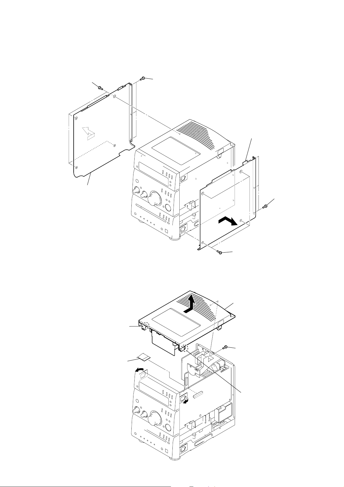
3-2. PANEL (SIDE L)/(SIDE R)
2
four screws
(BVTP3
×
8)
1
three screws
(BVTP3
HCD-GPZ6/GPZ7
×
8)
6
panel (side R)
3
panel (side L)
3-3. TOP BLOCK SECTION
2
4
flexible board
(CN307)
claw
3
5
four screws
(BVTP3
5
top block section
1
screw
(BVTP3 × 8)
4
three screws
(BVTP3
×
8)
×
8)
2
claw
7

HCD-GPZ6/GPZ7
3-4. FRONT PANEL BLOCK
9
front panel block
6
screw
(BVTP3
2
three connectors
(CN302, 308, 310)
×
8)
7
harness
1
flexible board
(CN312)
3
3-5. MAIN BOARD
1
flexible board
(CN313)
two screws
(BVTP3
×
8)
4
two screws
(BVTP3 × 8)
8
2
three connectors
(CN306, 309, 314)
two claws
5
two harnesses
4
screw
(BVTP3
×
8)
5
7
connector
(CN303)
8
MAIN board
3
screw
(BVTP3 × 8)
6
two flexible boards
(CN304, 305)
8
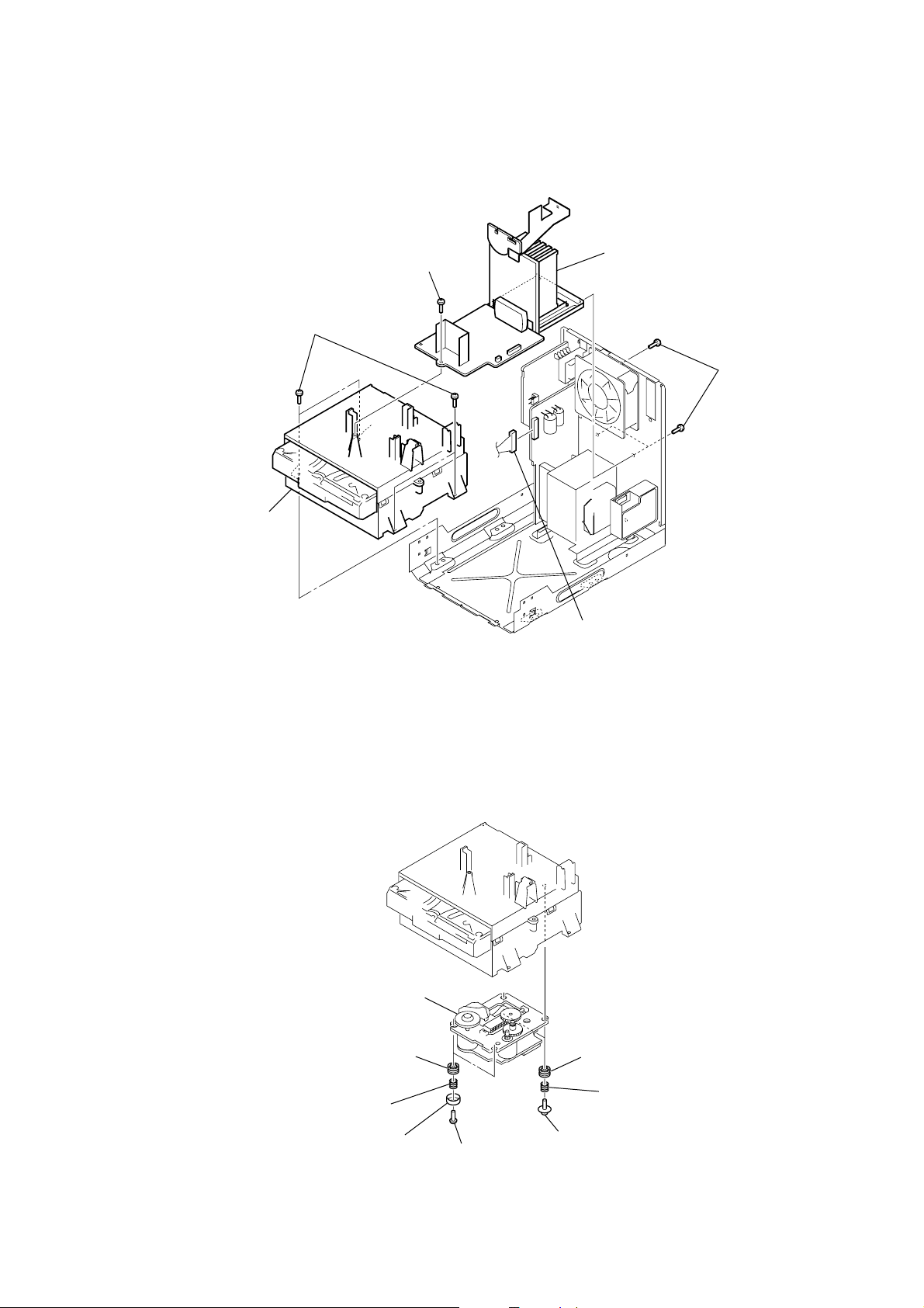
3-6. CD BLOCK ASSY
5
four screws
(BVTP3
HCD-GPZ6/GPZ7
3
screw
(BVTP3
×
8)
×
8)
4
AMP board block
2
three screws
(BVTP3
×
8)
6
CD block assy
3-7. BASE UNIT
(BU-F1BD83)
1
connector
(CN902)
8
base unit (BU-F1BD83)
4
two insulators
3
two coil springs
(insulator)
2
two stoppers
(BU)
1
two screws
(BTTP M2.6)
7
two insulators
6
two coil springs
(insulator)
5
two floating screws
(PTPWHM2.6)
9

HCD-GPZ6/GPZ7
)
3-8. BD BOARD
4
BD board
2
wire (flat type) (16 core
(CN301)
1
Remove four solders.
3-9. CD MECHANISM DECK
(CDM80B-F1BD83)
2
three claws
6
CD mechanism deck (CDM80B-F1BD83)
2
claw
3
screw (2.6 × 8)
1
two screws
(B3)
3
holder (mecha upper)
2
two claws
10
4
four screws
(B3)
5
holder (mecha lower)
3-10. HOLDER (BU215) ASSY
5
coil spring (holder down B)
1
screw
(BVTP 2.6
2
lever (CL UP2)
HCD-GPZ6/GPZ7
×
8)
6
3-11. CHASSIS (TOP)
3
5
chassis (top)
holder (BU215) assy
4
three screws
(BVTT 2.6)
two screws
(P 2 × 10)
4
floating screw
(PTPWHM2.6)
3
floating screw
(PTPWHM2.6)
1
screw
(BVTP 2.6 × 8)
2
lever (CL UP2)
11

HCD-GPZ6/GPZ7
3-12. LEVER (LOADING-L/R)
5
lever (loading-R)
1
SPT-T (loading-R) SPR-T (loading-L)
4
two hooks
1
2
two hooks
3
lever (loading-L)
12
PRECAUTION DURING LEVER (LOADING R / L) INSTALLATION
– Bottom view –
Align the horizontal position.
lever (loading-L)
Install the
both levers so that they move symmetrically.
lever (loading-R)

3-13. LEVER (DISC SENSOR)/(DISC STOP)
d
1
gear (cap)
2
gear (IDL-L)
HCD-GPZ6/GPZ7
PRECAUTION DURING DISC STOP LEVER INSTALLATION
5
two hooks
6
lever (disc stop)
3-14. DRIVER BOARD
3
two claws
4
lever (disc sensor)
hole
hole
Install the lever (disc stop) so that the both holes
are aligned.
2
two screws
(BVTT 2.6)
5
DRIVER boar
chassis (top)
lever (disc stop)
3
Remove two solders.
4
motor (pully) assy
(loading)
1
belt (MOT)
13

HCD-GPZ6/GPZ7
3-15. LEVER (BU LOCK)
5
lever (BU lock)
2
gear (cap)
3
gear (BU lock)
1
floating screw
(PTPWHM2.6)
4
three hooks
3-16. CLOSE LEVER
3
claw
5
close lever
1
washer (3-1-0.4)
2
4
shaft disc stop
SPR-E lever close
14

3-17. LEVER (DIR), GEAR (IDL-B)
2
washer
1
tension coil spring
(DIR)
claw
0
lever (DIR)
3
nylon washer 1.7
4
pulley (gear)
5
gear (cap)
6
gear (IDL-A)
qa
gear (IDL-B)
HCD-GPZ6/GPZ7
9
stopper
7
Loosen the screw.
8
Hold the release lever
and change the direction.
3-18. GEAR (IDL-C)
1
3
gear (IDL-D)
2
two claws
gear (IDL-F)
7
gear (IDL-C)
4
three hooks
5
gear loading lever
6
claw
15

HCD-GPZ6/GPZ7
3-19. AU-TC BOARD
1
connector
3
AU-TC board
2
screw (B2.6)
3-20. MECHANICAL DECK
(CMAL5Z232A)
6
mechanical deck (CMAL5Z232A)
1
connector
(CN301)
16
4
screw (B2.6)
5
bracket (CST)
1
two screws
(B2.6)
3
screw (B2.6)
2
two screws
(B2.6)

SECTION 4
TEST MODE
HCD-GPZ6/GPZ7
[COMMON TEST MODE]
• This mode is used to check operations of Amplifier.
Procedure:
1. Press the I/1 key to turn the power ON.
2. Press three keys of [DSGX] and [DISPLAY] and [PLAY MODE]
simultaneously.
3. When the COMMON test mode is activated, “PLAY SLEEP”
blinks on the fluorescent indicator tube.
4. Turn the [BASS] knob counterclockwise, “TONE MIN” is
displayed on the fluorescent indicator tube. Turn the [BASS]
knob clockwise, “TONE MAX” is displayed on the fluorescent
indicator tube.
Turn the [TREBLE] knob clockwise or counterclockwise,
“TONEFLAT” is displayed on the fluorescent indicator tube.
Turn the [VOLUME] knob counterclockwise, “VOL MIN” is
displayed on the liquid crystal display. Turn the [VOLUME]
knob clockwise, “VOL MAX” is displayed on the fluorescent
indicator tube.
5. To release this mode, press the I/1 key.
[PANEL TEST MODE]
• This mode is used to check the fluorescent indicator tube, LED,
model, destination, software version and key.
Procedure:
1. Press the I/1 key to turn the power ON.
2. Press three keys of [DSGX], [DISPLAY] and [FUNCTION]
simultaneously.
3. Fluorescent indicator tube is all turned on and each LED
of CD u , [TUNER/BAND], TAPE B , [DSGX] and
[STANDBY] blinks every 0.5 seconds.
4. When you want to enter the model, destination and version display
mode, press the [PLAY MODE] key. The model and destination
are displayed alternately on the fluorescent indicator tube.
5. Each time [PLAY MODE] key is pressed, the display changes
starting from MC version, GC version, CD version, CDD
version, CDMA version, CDMB version, BDA version, BDB
version, ST version, TA version, TM version, and TC version
this order, and returns to the MC version display on the
fluorescent indicator tube.
6. Press the [CD SYNC] key, the key check mode is activated.
7. In the key check mode, the fluorescent indicator tube displays
“K 0 J0 V0”.
8. Each time a button is pressed, “K” value increases. However,
once a button is pressed, it is no longer taken into account.
All keys are pressed, display becomes “K26”.
9. “V” value increases 1, 2, 3 ... if turn the [VOLUME] knob
clockwise, or it decreases 0, 9, 8 ... if turn the knob
counterclockwise
“J” value increases like 1, 2, 3 ... if turn the [BASS] or [TREBLE]
or JOG knob clockwise, or it decreases like 0, 9, 8 ... if turn
the knob counterclockwise.
10. When [FUNCTION] key is pressed while the version numbers
are being displayed except model and destination, year, month
and day of the software creation display. When [FUNCTION]
key is pressed again, the display returns to the software version
display. In this state, each time [PLAY MODE] key is pressed,
the year, month and day of creation of the software versions
are displayed on the fluorescent indicator tube in the same
order of version display.
11. To release this mode, press three keys in the same manner as
step 2, or disconnect the power cord.
[COLD RESET]
• The cold reset clears all data including preset data stored in
the RAM to initial conditions. Execute this mode when
returning the set to the customer.
Procedure:
1. Press the I/1 key to turn the power ON.
2. Press three keys of I/1 , [DISPLAY] and x (CD)
simultaneously.
3. The fluorescent indicator tube becomes blank instantaneously,
and the set is reset.
[SHIP MODE (NO MEMORY CLEAR)]
• This mode moves the optical pick-up to the position durable
to vibration. Use this mode when returning the set to the
customer after repair.
Procedure:
1. Press the I/1 key to turn the power ON.
2. Press the [FUNCTION] key to select “CD”.
3. Press three keys of [DISPLAY], Z and M L
simultaneously.
4. After the “STANDBY” display blinks, “LOCK” is displayed
on the fluorescent indicator tube, and the ship mode is set.
[SHIP MODE (MEMORY CLEAR)]
• This mode moves the optical pick-up to the position durable
to vibration. Use this mode when returning the set to the
customer after repair.
Procedure:
1. Press the I/1 key to turn the power ON.
2. Press the [FUNCTION] key to select “CD”.
3. Press three keys of [DSGX], x (CD) and [DISPLAY] simulta-
neously.
4. After the “STANDBY” display blinks, “LOCK” is displayed
on the fluorescent indicator tube, and the ship mode is set.
[CD SLOT LOCK MODE]
• This mode is used to unable to take sample disc out of disc
slot in the shop.
Procedure:
1. Press the I/1 key to turn the power ON.
2. Press the [FUNCTION] key to select “CD”.
3. While pressing the Z key, press the x (CD) key for
5 seconds.
4. The message “LOCKED” is displayed on the fluorescent
indicator tube and the disc slot is locked. (Even if pressing
the Z key, the message “LOCKED” is displayed on the
fluorescent indicator tube and the disc slot is locked)
5. To release from this mode, pressing the Z key, press
the x (CD) key for 5 seconds.
6. The message “UNLOCKED” is displayed on the fluorescent
indicator tube and the disc slot is unlocked.
[CD SERVICE MODE]
• This mode can run the CD sled motor freely. Use this mode,
for instance, when cleaning the optical pick-up.
Procedure:
1. Press the I/1 key to turn the power ON.
2. Press the [FUNCTION] key to select “CD”.
3. Press three keys of [ENTER], M L and [DISPLAY]
simultaneously.
4. Press the M L key to move the optical pick-up to outside
track, or press the l m key to inside track.
5. Press the x (CD) key, “LD OFF” is displayed and laser diode
is turned off. Each time x (CD) key is pressed, laser diode
ON/OFF switch is performed.
6. To release this mode, press the I/1 key.
17

HCD-GPZ6/GPZ7
[CD ERROR CODE DISPLAY MODE]
This mode can be used for error code display of CD section.
Procedure:
1. Press the I/1 button to turn the power on.
2. Press the [FUNCTION] key to select “CD”.
3. Press three keys of [DISPLAY], [DSGX] and M L
simultaneously.
4. When this mode is activated, mechanism deck error code is
displayed on the fluorescent indicator tube.
5. Press the + − keys to changed over between optical
pick-up error code display mode and mechanism deck error
code mode.
6. Turn the l mM L keys to change over display of
error history.
[CD SERVO TEST MODE]
• This mode used to check operation of optical pick-up.
Procedure:
1. Press the I/1 key to turn the power ON.
2. Press the [FUNCTION] key to select “CD”.
3. Press three keys of [DISPLAY], [ENTER] and l m
simultaneously.
4. When the CD servo test mode is activated. In this state, each
time [PLAY MODE] key is pressed, tracking ON/OFF switch
is performed.
[CD POWER MANAGE]
This mode is for switch the CD power supply on/off. Even if this
state pulls out AC plug, it is held.
Procedure:
1. Press the I/1 button to turn the power on.
2. Press the [FUNCTION] key to select “CD”.
3. Press the I/1 button again to turn the power off (standby).
4. While pressing the x (CD) button, press the I/1 button.
5. It turns power on and display “CD POWER”, then display
“ON” or “OFF”.
18

r
e
V
SECTION 5
MECHANICAL ADJUSTMENTS
HCD-GPZ6/GPZ7
SECTION 6
ELECTRICAL ADJUSTMENTS
• Precaution
1. Clean the following parts with a denatured-alcohol-moistened
swab :
record/playback head pinch roller
erase head rubber belts
capstan idlers
2. Demagnetize the record/playback head with a head
demagnetizer. (Do not bring the head magnetizer close to the
erase head.)
3. Do not use a magnetized screwdriver for the adjustments.
4. After the adjustments, appiy suitable locking compound to
the parts adjusted.
5. The adjustments should be performed with the rated power
supply voltage unless otherwise noted.
• Torque Measurement
Mode Torque Meter Meter Reading
2.95 – 6.86 mN⋅m
FWD CQ-102C (30 – 70 g⋅cm)
(0.42 – 0.97 oz⋅inch)
FWD
Back Tension
FF CQ-201B (more than 60 g⋅cm)
REW CQ-201B (more than 60 g⋅cm)
CQ-102C (1.5 – 5.5 g⋅cm)
0.15 – 5.39 mN⋅m
(0.021 – 0.076 oz⋅inch)
more than 5.89 mN⋅m
(more than 0.83 oz⋅inch)
more than 5.89 mN⋅m
(more than 0.83 oz⋅inch)
• Tape T ension Measurement
Mode Tension Meter Meter Reading
FWD CQ-403A
more than 100 g
(more than 3.53 oz)
0 dB=0.775 VDECK SECTION
1. Demagnetize the record/playback head with a head
demagnetizer.
2. Do not use a magnetized screwdriver for the adjustments.
• Test T ape
Tape Signal Used for
P-4-A063 6.3 kHz, -10 dB Azimuth Adjustment
RECORD/PLA YBA CK HEAD AZIMUTH ADJUSTMENT
Procedure:
1. Mode: Playback
test tape
P-4-A063
(6.3 kHz,
−
10 dB)
2. Turn the adjustment screw and check output peaks. If the peaks
do not match for L-CH and R-CH, turn the adjustment screw
so that outputs match within 1dB of peak.
L-CH
peak
Output
level
PANEL (2) board
PHONES jack
(J321)
set
within
1dB
level mete
+
–
within
1dB
Adjustment Location: Record/Playback/Erase Head
forward
reverse
CD SECTION
Note:
1. CD Block is basically constructed to operate without adjustment.
2. Use YEDS-18 disc (3-702-101-01) unless otherwise indicated.
3. Use an oscilloscope with more than 10 MW impedance.
4. Clean the object lens by an applicator with neutral detergent when the
signal level is low than specified value with the following checks.
5. Check the focus bias check when optical pick-up block is replaced.
FOCUS BIAS CHECK
oscilloscop
(DC range)
BD board
TP (RFACI)
TP (VC)
Procedure :
1. Connect oscilloscope to TP (RFACI) and TP (VC) on the BD
board.
2. Press the I/1 button to turn the power ON, and press
the Z (CD) button to open the CD disc tray.
3. Set disc (YEDS-18) on the tray and press the CD u button
to playback.
4. Confirm that oscilloscope waveform is as shown in the figure
below. (eye pattern)
A good eye pattern means that the diamond shape (◊) in the
center of the waveform can be clearly distinguished.
+
–
VOLT/DIV: 200 m
TIME/DIV: 500 ns
level:
0.9
±
0.4 Vp-p
R-CH
Screw
position
peak
L-CH
peak
R-CH
peak
Screw
position
Checking Location:
– BD Board (Conductor Side) –
3. Mode: Playback
test tape
P-4-A063
(6.3 kHz, −10 dB)
in phase 45°90°135°180
PANEL (2) board
PHONES jack
(J321)
set
waveform of oscilloscope
good
oscilloscope
V
°
wrong
H
TP
(VC)
IC201
TP
(RFACI)
HCD-GPZ6/GPZ7
the pats adjusted.
1919
4. After the adjustments, apply suitable locking compound to

HCD-GPZ6/GPZ7
SECTION 7
DIAGRAMS
7-1. BLOCK DIAGRAM – CD SERVO/TUNER Section –
OPTICAL
PICK-UP BLOCK
(KSM-215DCP)
A
B
C
D
E
F
AUTOMATIC
POWER CONTROL
Q321
FOCUS/TRACKING COIL DRIVER,
SLED/SPINDLE MOTOR DRIVER
12
CH2OUTF
IC402
CH2FIN
6
2-AXIS
DEVICE
LD
PD
FCS+
70
RFACO
57
A
58
B
59
C
60
D
50
E
51
F
66
LD
67
PD
CD DSP
IC201
45
FFDR
71
RFACI
DOUT
AOUT1
AOUT2
XTAO
SSTP
XTAI
OPTICAL
101
112
117
109
108
X202
16.9344MHz
TRANSCEIVER
R-CH
J302
MD Link
CD DIGITAL
OUT
MUTING
Q102
CD-L
B
• R-ch is omitted due to same as L-ch.
(Page 21)
• SIGNAL PATH
S201
(LIMIT)
39
D +3.3V
SYSTEM CONTROLLER
IC306 (1/3)
CD MUTING
CONTROL
Q317, 318
R-CH
: TUNER
: CD PLAY (ANALOG)
: CD PLAY (DIGITAL)
M402
(SLED)
M401
(SPINDLE)
(Page 21)
FCS–
TRK+
TRK–
SL+
M
SL–
SP+
M
SP–
TUNER-L
A
11
13
14
17
16
CH2OUTR
CH1OUTR
CH1OUTF
CH3OUTF
CH3OUTR18
CH4OUTF
CH4OUTR15
MUTE
20
CH2RIN
CH1RIN
CH1FIN
CH3FIN
CH3RIN 22
OPIN+
OPOUT
CH4IN
7
5
4
23
3
27
24
46
44
43
41
42
38
FRDR
TRDR
TFDR
SFDR
SRDR
MDP
M701
(LOADING)
TUNER UNIT
XRST
8
M
XLAT-MP3
SSTB-MP3
MOTOR DRIVE
DATA
CLOK
XLAT
SENS
SCOR
DATA2
CLK2
REQ-MP3
IREQ-MP3
ACK-MP3
XTACN
LOADING
IC701
89
11
16
20
26
12
90
13
14
10
15
85
7
S701
(OUT)
S702
(CHUCK)
35
CD DATA
37
CD CLK
23
CD XLT
36
CD SENS
19
CD SCOR
6
MP3 DATA IN
5
MP3 DATA OUT
7
MP3 CLK
25
MP3 XLAT
26
MP3 REQ
27
MP3 IREQ
24
MP3 ACK
28
MP3 STB
33
XTCN
22
CD XRST
53
CDM80 LOAD-OUT
54
CDM80 LOAD-IN
56
(OUT SW) CDM80 SW1
57
(CHECK SW) CDM80 SW2
CD AMUTE
38
HCD-GPZ6/GPZ7
ANTENNA
FM 75Ω
AM
FM ANT
ANT GND
AM ANT
ANT GND
L OUT
R OUT
ST DIN
DO/STEREO
ST CLK
ST CE
TUNED
RDS DATA
RDS CLK
2020
R-CH
77
ST DATA OUT
78
DIN/STEREO
79
ST CLK
76
ST CE
75
ST TUNED
21
RDS DATA
18
RDS-CLK

7-2. BLOCK DIAGRAM – MAIN Section –
HCD-GPZ6/GPZ7
HRPE350
(REC/PB/ERASE)
L-CH
R-CH
ERASE
R-CH
TAPE MECHANISM
DECK BLOCK
M+10V
MM
CAPSTAN/
REEL
TRGM+
(Page 20)
(Page 20)
PB
MUTING
Q101
BIAS OSC
T301
CAPSTAN/REEL
MOTOR DRIVE
Q310, 311
PLUNGER
DRIVE
Q308, 309
J320
MD Link
ANALOG IN
CD-L
B
TUNER-L
A
REC
MUTING
Q103, 104
R-CH R-CH
MUTING
CONTROL
Q322, 323
BIAS OSC
Q321
TC CONT
TC TRG
REC BIAS
SWITCH
Q306, 307
R-CH
BIAS TRAP
T101
BIAS
R/P
59
61
63
11
7
3
15
MD IN L
CD IN L
TU IN L
TAPE IN L
PB
OUT L
TAPE L
REC OUT L
19SI18
AC DET
INPUT SELECT,
TONE CONTROL,
ELECTRICAL VOLUME
IC302
TONE
OUT
EQ
SC
VOL
IN L
36
37
VOL
OUT L
DETECT
Q607
POWER AMP
D609
IC601
STANDBY
SWITCH
Q604
D608
PROTECT
SWICTH
Q608
OVER LOAD
DETECT
Q502
+
PROTECT
CONTROL
IC602
OCP
1
OUT
R-CH
RELAY
RELAY
Q609
DRIVE
Q610, 611
R-CH
VP
2
4
CT
3
OFF SWITCH
33
MUTING
Q501
R-CH
MUTING
CONTROL
Q602, 603
TEMPERATURE
THP822
+
M +10V
R-CH
RY301
RELAY
B+ SWITCH
Q605, 606
CD UNREG
D313
FAN MOTOR
DRIVE
Q301, 302,
Q315, 316
C
+
–
+
–
M
(Page 22)
J321
PHONES
L
R
M301
(FAN)
TM301
SPEAKER
IMPEDANCE
USE 6 – 16Ω
HCD-GPZ6/GPZ7
PACK
F REC
END SW
PLAY SW
HALF
END SW
PLAY SW
TC TRG
TC CONT
59
60
TC TRG
TC CAPM CONT
BIAS
HALF
END SW
PLAY SW
95
58
94
61
TC PLAY
TC END SW
TC HALF/REC SW
R/P
63
TC R/P
BIAS ON
70
71
AMP-CLK
AMP-DATA
66
SYSTEM CONTROLLER
IC306 (2/3)
LINE MUTE
2121
XIN
15
X302
16MHz
XOUT11XCOUT
13
32.768kHz
X301
XCIN
10
69
67
AMP POWER
HP DETECT
68
PROTECT
FAN ON
SP RELAY
65
87
• R-ch is omitted due to same as L-ch.
• SIGNAL PATH
: TUNER
: CD PLAY (ANALOG)
: TAPE PLAY
: TAPE REC
: AUX IN

HCD-GPZ6/GPZ7
7-3. BLOCK DIAGRAM – PANEL/POWER SUPPLY Section –
S701 – 707,
S708 – 717,
S718 –726
S801
BASS
S802
TREBLE
S803
VOLUME
S804
(JOG)
REMOTE CONTROL
RECEIVER
IC802
ROTARY
ENCODER
ROTARY
ENCODER
ROTARY
ENCODER
ROTARY
ENCODER
D316
SYSTEM CONTROLLER
4
SIRCS IN/
WAKE
KEY1 – KEY3
90 – 92
74 KEY WAKE UP
42 ELV E1/BASS A
43 ELV E0/BASS B
40 ELV E3/TRE A
41 ELV E2/TRE B
88 VOL A
89 VOL B
97 SEARCH A
100 SEARCH B
IC306 (3/3)
FL DATA
FL DRIVER
IC801
GR1 – GR12
SG1 – SG16
39
81FL CLK
80FL STB
3STBY LED
7DIN
8CLK
9STB
LED DRIVE
Q800
LED DRIVE
Q805
31 – 42
14 – 29
1LED1
2LED2
3LED3
4LED4
FL701
FLUORESCENT
INDICATOR
TUBE
D805
STANDBY
D801
CD
u
D802
TUNER/
BAND
D803
TAPE
B
D804
DSGX
FL –30V
FL AC
FL AC
–33V REGULATOR
Q901 – 903
+POWER
–POWER
RECT
D901
RECT
D910
F901
F902
T901
MAIN POWER
TRANSFORMER
RESET
AC-CUT
UNREG
+9V
VM +7V
+4V
IC308
REGULATOR
IC304
+10V
REGULATOR
IC310
+7V
REGULATOR
IC305
D912 – 915
CD UNREG
RECT
RECT
D902 – 905
RECT
D906 – 909
D916
T902
SUB POWER
TRANSFORMER
RY901
RELAY DRIVE
Q319, 320
AC DET
(AC IN)
C
(Page 21)
+2.5V
D +2.5V
34CD BD POWER
12
20
REGULATOR
IC202
RESET SWITCH
Q314
D +3.3V
A +3.3V
D312
D311
EVOL +3.3V
U-COM B+
VOLTAGE DETECT
IC309
B+ SWITCH
Q312, 313
D314
+3.3V
D +4V
REGULATOR
D302
D303
A+9V
M+10V
+4V
IC307
REGULATOR
HCD-GPZ6/GPZ7
72STBY-RELAY
2222
HCD-GPZ6/GPZ7
• Note for Printed Wiring Boards and Schematic Diagrams
Note on Printed Wiring Board:
• X : parts extracted from the component side.
• Y : parts extracted from the conductor side.
• W : indicates side identified with part number.
f
•
• : Pattern from the side which enables seeing.
(The other layers' patterns are not indicated.)
Caution:
Pattern face side: Parts on the pattern face side seen from
(Conductor Side) the pattern face are indicated.
Parts face side: Parts on the parts face side seen from
(Component Side) the parts face are indicated.
• Indication of transistor.
: internal component.
C
Q
B
E
Q
B
CE
These are omitted.
These are omitted.
Note on Schematic Diagram:
• All capacitors are in µF unless otherwise noted. (p: pF)
50 WV or less are not indicated except for electrolytics
and tantalums.
• All resistors are in Ω and 1/
specified.
• f : internal component.
• 2 : nonflammable resistor.
• 5 : fusible resistor.
• C : panel designation.
Note: The components identified by mark 0 or dotted line
with mark 0 are critical for safety.
Replace only with part number specified.
• A : B+ Line.
• Voltages and waveforms are dc with respect to ground
under no-signal (detuned) conditions.
– BD Board –
no mark : CD PLAY
– Other Section –
no mark : TUNER
(): CD PLAY
[]: TAPE PLAY
〈〈 〉〉 : TAPE REC
• Voltages are taken with a VOM (Input impedance 10 MΩ).
Voltage variations may be noted due to normal production tolerances.
• Waveforms are taken with a oscilloscope.
Voltage variations may be noted due to normal production tolerances.
• Circled numbers refer to waveforms.
• Signal path.
F : TUNER
E : TAPE PLAY
a : TAPE REC
J : CD PLAY (ANALOG)
c : CD PLAY (DIGITAL)
L : AUX IN
4
W or less unless otherwise
• Circuit Boards Location
MAIN board
PANEL (1) board
PANEL (2) board
OPTICAL board
AU-TC board
DRIVER board
SUB PT board
POWER board
THERMISTOR board
AMP board
BD board
HCD-GPZ6/GPZ7
2323
 Loading...