

Sony HCD-GNZ77D, HCD-GNZ88D Service Manual

HCD-GNZ77D/GNZ88D
SERVICE MANUAL
Ver. 1.4 2009.10
• HCD-GNZ77D/GNZ88D are the
tuner, deck, DVD and amplifier
section in MHC-GNZ77D/GNZ88D.
(Photo: HCD-GNZ77D)
DVD
Section
Tape Deck
Section
Model Name Using Similar Mechanism HCD-GNZ7D/GNZ8D/GNZ9D
DVD Mechanism Type CDM74HF-DVBU101//C
Optical Pick-up Name KHM-310CAB/C2NP
Model Name Using Similar Machanism NEW
E Model
Amplifier section
HCD-GNZ88D
The following measured at AC 120, 127, 220, 240 V,
50/60 Hz
DIN power output (rated)
75 W + 75 W
(4 ohms at 1 kHz, DIN)
Continuous RMS power output (reference)
Front speaker: 100 W + 100 W
(4 ohms at 1 kHz, 10%
THD)
Center speaker: 40 W (8 ohms at 1 kHz,
10% THD)
Surround speaker: 40 W + 40 W
(8 ohms at 1 kHz, 10%
THD)
HCD-GNZ77D
The following measured at AC 120, 127, 220, 240 V,
50/60 Hz
DIN power output (rated)
75 W + 75 W
(4 ohms at 1 kHz, DIN)
Continuous RMS power output (reference)
100 W + 100 W
(4 ohms at 1 kHz, 10%
THD)
Inputs
VIDEO INPUT (phono jacks):
VIDEO: 1 Vp-p, 75 ohms
AUDIO L/R: Voltage 250 mV,
impedance 47 kilohms
TV/SAT AUDIO IN L/R (phono jack):
Voltage 250 mV/450 mV,
impedance 47 kilohms
SPECIFICATIONS
Outputs
VIDEO OUT (phono jack):
max. output level
1 Vp-p, unbalanced, Sync
negative load impedance
75 ohms
COMPONENT VIDEO OUT:
Y: 1 Vp-p, 75 ohms
PB/CB: 0.7 Vp-p, 75 ohms
PR/CR: 0.7 Vp-p, 75 ohms
S-VIDEO OUT (4-pin/mini-DIN jack):
Y: 1 Vp-p, unbalanced,
Sync. negative
C: 0.286 Vp-p, load
impedance 75 ohms
PHONES (stereo mini jack):
Accepts headphones of
8 ohms or more
FRONT SPEAKER: Use only the supplied speakers
SURROUND SPEAKER (HCD-GNZ88D):
Use only the supplied speakers
CENTER SPEAKER (HCD-GNZ88D):
Use only the supplied speakers
SUB WOOFER OUT (phono jack):
Voltage 250 mV,
impedance 1 kilohm
– Continued on next page –
DVD DECK RECEIVER
9-887-258-05
2009J04-1
© 2009.10
Sony Corporation
Audio&Video Business Group
Published by Sony Techno Create Corporation
1

HCD-GNZ77D/GNZ88D
Disc player section
System Compact disc and digital
audio and video system
Laser Semiconductor laser
(DVD: λ=650 nm,
CD: λ=790 nm)
Emission duration:
continuous
Frequency response DVD (PCM 48 kHz):
2 Hz – 22 kHz (±1 dB)
CD: 2 Hz – 20 kHz (±0.5 dB)
Video color system format
Latin American model:
NTSC
Other models: NTSC, PAL
Tape deck section
Recording system 4-track 2-channel stereo
Frequency response 50 – 13,000 Hz (±3 dB),
using Sony TYPE I tape
Tuner section
FM stereo, FM/AM superheterodyne tuner
FM tuner section
Tuning range 87.5 – 108.0 MHz
(50-kHz step)
Antenna FM lead antenna
Antenna terminals 75 ohm unbalanced
Intermediate frequency 10.7 MHz
AM tuner section
Tuning range
Saudi Arabian model: 531 – 1,602 kHz (with the
interval set at 9 kHz)
Other models: 531 – 1,602 kHz (with the
interval set at 9 kHz)
530 – 1,710 kHz (with the
interval set at 10 kHz)
Antenna AM loop antenna
Antenna terminals External antenna terminal
Intermediate frequency 450 kHz
General
Power requirements
Saudi Arabian model: 120 – 127 V, 120 – 220 V or
220 – 240 V AC,
50/60 Hz
Adjustable with voltage
selector
Thai model: 220 V AC, 50/60 Hz
Other models: 120 V or 220 – 240 V AC,
50/60 Hz
Adjustable with voltage
selector
Power consumption
MHC-GNZ88D 100 watts
MHC-GNZ77D 75 watts
Dimensions (w/h/d) (Approx.)
280 × 326 × 385.5 mm
Mass (Approx.)
HCD-GNZ88D 6.5 kg
HCD-GNZ77D 6.4 kg
Design and specifications are subject to change without
notice.
SAFETY-RELATED COMPONENT WARNING!!
COMPONENTS IDENTIFIED BY MARK 0 OR DOTTED LINE
WITH MARK 0 ON THE SCHEMATIC DIAGRAMS AND IN
THE PARTS LIST ARE CRITICAL TO SAFE OPERATION.
REPLACE THESE COMPONENTS WITH SONY P ARTS WHOSE
PART NUMBERS APPEAR AS SHOWN IN THIS MANUAL OR
IN SUPPLEMENTS PUBLISHED BY SONY.
2

HCD-GNZ77D/GNZ88D
Ver. 1.1
Notes on Chip Component Replacement
•Never reuse a disconnected chip component.
• Notice that the minus side of a tantalum capacitor may be
damaged by heat.
Flexible Circuit Board Repairing
•Keep the temperature of soldering iron around 270°C during
repairing.
• Do not touch the soldering iron on the same conductor of the
circuit board (within 3 times).
• Be careful not to apply force on the conductor when soldering
or unsoldering.
UNLEADED SOLDER
Boards requiring use of unleaded solder are printed with the lead
free mark (LF) indicating the solder contains no lead.
(Caution: Some printed circuit boards may not come printed with
the lead free mark due to their particular size)
: LEAD FREE MARK
Unleaded solder has the following characteristics.
• Unleaded solder melts at a temperature about 40 °C higher than
ordinary solder.
Ordinary soldering irons can be used but the iron tip has to be
applied to the solder joint for a slightly longer time.
Soldering irons using a temperature regulator should be set to about
350 °C.
Caution: The printed pattern (copper foil) may peel away if the
heated tip is applied for too long, so be careful!
• Strong viscosity
Unleaded solder is more viscou-s (sticky , less prone to flo w) than
ordinary solder so use caution not to let solder bridges occur such
as on IC pins, etc.
• Usable with ordinary solder
It is best to use only unleaded solder but unleaded solder may also
be added to ordinary solder.
NOTES ON LASER DIODE EMISSION CHECK
The laser beam on this model is concentrated so as to be focused on
the disc reflective surface by the objective lens in the optical pickup block. Therefore, when checking the laser diode emission,
observe from more than 30 cm away from the objective lens.
Laser component in this product is capable
of emitting radiation exceeding the limit for
Class 1.
This appliance is
claassified as a CLASS 1
LASER product. This
label is located on the
rear exterior.
NOTE ON REPLACEMENT OF DMB15 BOARD
New part of EEPROM (IC103) on the DMB15 board cannot be
used. Therefore, if the mounted DMB15 board (A-1167-719-A, etc.)
is replaced, exchange new EEPR OM (IC103) with that used before
the replacement.
CAUTION
Use of controls or adjustments or performance of procedures
other than those specified herein may result in hazardous
radiation exposure.
NOTES ON HANDLING THE OPTICAL PICK-UP BLOCK
OR BASE UNIT
The laser diode in the optical pick-up block may suffer electrostatic
breakdown because of the potential difference generated by the
charged electrostatic load, etc. on clothing and the human body.
During repair, pay attention to electrostatic break-down and also
use the procedure in the printed matter which is included in the
repair parts.
The flexible board is easily damaged and should be handled with
care.
3

HCD-GNZ77D/GNZ88D
MODEL IDENTIFICATION
– BACK PANEL –
PARTS No.
MODEL PARTS No.
GNZ88D: E3, E15 2-663-830-0s
GNZ88D: EA 2-663-830-1s
GNZ88D: SP 2-663-830-2s
GNZ88D: E12, E13 2-663-830-3s
GNZ88D: PH 2-663-830-5s
GNZ88D: TH 2-663-830-6s
GNZ77D: E3, E15 2-663-831-0s
GNZ77D: E2 2-663-831-1s
GNZ77D: EA 2-663-831-2s
GNZ77D: MY, SP 2-663-831-3s
GNZ77D: E12, E13 2-663-831-4s
GNZ77D: PH 2-663-831-6s
GNZ77D: TH 2-663-831-7s
• Abbreviation
E2 : 120 V AC area in E model
E3 : 240 V AC area in E model
E12 : 220-240 V AC area in E model
E13 : 220-230 V AC area in E model
E15 : Iran model
EA : Saudi arabia model
PH : Philippine model
SP : Singapore model
MX : Mexican model
TH : Thai model
MY : Malaysia model
4

TABLE OF CONTENTS
HCD-GNZ77D/GNZ88D
1. GENERAL
Main Unit ................................................................................ 6
Remote Control ....................................................................... 8
2. DISASSEMBLY
2-1. Cabinet Steel Case............................................................. 10
2-2. Loading Panel.................................................................... 10
2-3. Front Panel Section ........................................................... 11
2-4. DVD Block Section........................................................... 11
2-5. Back Panel Section............................................................ 12
2-6. Main Board, ADC Board .................................................. 12
2-7. Speaker Board, S-Master Board........................................ 13
2-8. Power Board...................................................................... 13
2-9. Tape Mechanism Deck ...................................................... 14
2-10. Holder TC-R Assy, Holder TC-L Assy ............................. 14
2-11. Mic Board ......................................................................... 15
2-12. Karaoke Board, Video Board ............................................ 15
2-13. DMB15 Board ................................................................... 16
2-14. Sensor Board ..................................................................... 16
2-15. Motor (TB) Board ............................................................. 17
2-16. Motor (LD) Board ............................................................. 17
2-17. Pick-Up Unit ..................................................................... 18
2-18. SW Board, Driver Board................................................... 18
3. TEST MODE ..................................................................... 19
4. MECHANICAL ADJUSTMENTS............................... 23
5. ELECTRICAL ADJUSTMENTS................................. 24
6. DIAGRAMS
6-1. Block Diagram — RF/Servo Section — ........................... 27
6-2. Block Diagram — Video Section — ................................. 28
6-3. Block Diagram — Main Section —.................................. 29
6-4. Block Diagram — Audio Section — ................................ 30
6-5. Block Diagram — Function/Power Section —................. 31
6-6. Circuit Boards Location .................................................... 32
6-7. Printed Wiring Boards — Driver Section —..................... 34
6-8. Schematic Diagram — Driver Section —......................... 35
6-9. Printed Wiring Board — DMB15 Section — ................... 36
6-10. Schematic Diagram — DMB15 Section (1/5) — ............. 38
6-11. Schematic Diagram — DMB15 Section (2/5) — ............. 39
6-12. Schematic Diagram — DMB15 Section (3/5) — ............. 40
6-13. Schematic Diagram — DMB15 Section (4/5) — ............. 41
6-14. Schematic Diagram — DMB15 Section (5/5) — ............. 42
6-15. Printed Wiring Board — Main Section — ........................ 43
6-16. Schematic Diagram — Main Section (1/4) — .................. 44
6-17. Schematic Diagram — Main Section (2/4) — .................. 45
6-18. Schematic Diagram — Main Section (3/4) — .................. 46
6-19. Schematic Diagram — Main Section (4/4) — .................. 47
6-20. Printed Wiring Board — S-Master Section —.................. 48
6-21. Schematic Diagram — S-Master Section (1/4) —............ 50
6-22. Schematic Diagram — S-Master Section (2/4) —............ 51
6-23. Schematic Diagram — S-Master Section (3/4) —............ 52
6-24. Schematic Diagram — S-Master Section (4/4) —............ 53
6-25. Printed Wiring Board — ADC Section — ........................ 54
6-26. Schematic Diagram — ADC Section —........................... 55
6-27. Printed Wiring Boards — Panel Section — ...................... 56
6-28. Printed Wiring Board — Volume Section — .................... 57
6-29. Schematic Diagram — Panel Section — .......................... 58
6-30. Printed Wiring Board — Mic Section — .......................... 59
6-31. Schematic Diagram — Mic Section —............................. 60
6-32. Printed Wiring Board — Karaoke Section — ................... 61
6-33. Schematic Diagram — Karaoke Section —...................... 62
6-34. Printed Wiring Board — Video Section — ....................... 63
6-35. Schematic Diagram — Video Section —.......................... 64
6-36. Printed Wiring Board — Speaker Section — ...................65
6-37. Schematic Diagram — Speaker Section — ...................... 66
6-38. Printed Wiring Board — Power Section — ...................... 67
6-39. Schematic Diagram — Power Section — ......................... 68
7. EXPLODED VIEWS
7-1. Main Section ..................................................................... 79
7-2. Front Panel Section (1)...................................................... 80
7-3. Front Panel Section (2)...................................................... 81
7-4. Front Panel Section (3)...................................................... 82
7-5. Chassis Section (HCD-GNZ88D) ..................................... 83
7-6. Chassis Section (HCD-GNZ77D) ..................................... 84
7-7. DVD Block Section........................................................... 85
7-8. DVD Mechanism Deck Section (1) .................................. 86
7-9. DVD Mechanism Deck Section (2) .................................. 87
8. ELECTRICAL PARTS LIST ........................................ 88
5

HCD-GNZ77D/GNZ88D
Illustrati
List of button locations and reference pages
SECTION 1
GENERAL
This section is extracted
from instruction manual.
How to use page 104 to 106
Use this page to find the location of buttons and other
parts of the unit and remote that are mentioned in the
text.
Unit
ALPHABETICAL ORDER
A — D
CD SYNC 8 (61)
Deck A wk (60)
Deck B qj (60–62, 75)
DIRECTION ea (60–62, 73, 75)
DISC 1 ~ 3 q; (25, 28, 29)
DISC SKIP/EX-CHANGE qa
(18, 23, 25)
Disc tray 7 (18, 19, 23, 26–29,
33–36, 38, 69–71, 86, 87, 91)
DISPLAY r; (21, 76, 77)
Display 4 (77)
DVD eh (18, 19, 21, 24, 25, 61,
62, 67, 72, 76, 88)
E — O
ECHO LEVEL1) ws (67)
EQ BAND/MEMORY 3 (64)
GROOVE qk (63)
ILLUMINATION el (58, 77, 90)
IR Receptor 2 (17, 85)
MASTER VOLUME ql (24, 56,
74, 77, 85)
MIC2) (jack) wh (67, 72, 85, 94)
1)
(jack) wh (67, 72, 85, 94)
MIC 1
1)
MIC 2
(jack) wg (67, 72, 85, 94)
MIC LEVEL2) wf (67, 72, 85)
MIC 1 LEVEL
MIC 2 LEVEL
1)
wf (67, 72, 85)
1)
wd (67, 72, 85)
P — Z
PHONES (jack) w; (85, 94)
Power illuminator wj (77)
PRESET EQ wl (63, 64)
REC PAUSE/START 6 (61, 62,
72)
SOUND FIELD 5 (65, 83)
SUB WOOFER ON/OFF
(67)
TAPE A/B ef
Tape lid qj wk (60)
TUNER/BAND eg (57–59, 76)
TUNING +/– qh (57–59)
TV/SAT1) ed (62, 76, 84, 86)
VIDEO
VIDEO INPUT
94)
(60–62, 72, 75, 76)
1)
es (62, 76, 84)
1)
TAPE A/B ef (60–62, 72, 75, 76)
Name of button/part Reference page
3)
ej
(jacks) wa (83,
on number
r
RR
SYMBOLS
?/1 (on/standby) ek (16, 18, 58,
84, 90)
Z OPEN/CLOSE 9 (18, 19, 23,
25, 86)
nN (play) qs (24–27, 31, 33,
35, 36, 38, 48, 51, 60–62, 73,
75, 85, 87)
. OPERATION DIAL >
(go backward/forward) 1
(24, 32, 34, 39, 59, 62, 64, 65)
mM (rewind/fast forward)
qh (24, 60, 88)
qh (25)
X (pause) qd (16)
x (stop) qf (61–62, 73, 86, 87,
90)
Z PUSH (Eject A) e; (60)
Z PUSH (Eject B) qg (60)
1)
Except for MHC-GNZ55D.
2)
MHC-GNZ55D only.
3)
MHC-GN999D/
MHC-GN999DS only.
6
104
GB

Top view
Front view
34 5 6
2
HCD-GNZ77D/GNZ88D
1
r;
el
ek
ej
eh
eg
ef
ed
es
ea
e;
wl
wk
wj
wh
wg
wf
wd
ws
wa
7
8
9
q;
qa
qs
qd
qf
qg
qh
qj
qk
ql
w;
Additional Information
continued
105
GB
7

HCD-GNZ77D/GNZ88D
Remote control
ALPHABETICAL ORDER
A — L
ADVANCE wf (25)
ALBUM +/– qa (20, 24)
ANGLE q; (44)
AUDIO 8 (34, 43, 67, 70, 83)
CLEAR wk (20, 27–30, 35, 41, 53)
DISC SKIP 3 (25, 28, 29)
DISPLAY ed (21, 76, 77)
ENTER wh(18–20, 27–31, 34, 36–39, 40, 42, 45–50,
53, 56–59, 68–71, 74–76, 90)
FM MODE 7 (59, 89)
FUNCTION +/– 4 (19, 24, 57–60, 67, 75, 84, 88)
KARAOKE MODE ea (68, 88)
KARAOKE PON e; (68)
KEY CONTROL #/2 es (69)
M — S
MENU qs (30, 32, 34–36, 39, 57, 58)
Numeric Buttons
1)2)
wl (17, 20, 21, 24, 30, 31, 41,
46–50, 59)
PICTURE NAVI 6 (35, 36, 41)
PRESET + qh (57–59)
PRESET – wd (57–59)
REPEAT 7 (30)
REPLAY wf (25)
3)
SCORE
5 (72)
SLEEP eg (20, 74)
SLOW qj (25)
SLOW ws (25)
SOUND FIELD 5
4)
qd3) (65, 83)
STEP C wf (25)
SUBTITLE 9 (44)
T — Z
THEATRE SYNC 1 (21)
TIMER MENU eh (18, 74–76)
TIME/TEXT ef (77–79)
TOP MENU wj (30)
TUNING + qj (57–59)
TUNING – ws (57–59)
2)
TV
w; (17)
2)
TV CH +
TV CH –
TV/VIDEO
TV VOL +/–
TV &/1
VOLUME +/–
qh (17)
2)
wd (17)
2)
eg (17)
1)2)
qf (17)
(on/standby)2) 2 (17)
1)
qf (24, 56, 74, 77, 85)
NUMBERS AND SYMBOLS
?/1 (on/standby) 2 (16, 18, 74, 75, 85)
x (stop) qk (24, 26, 32, 34–36, 39, 45, 58, 60, 75, 86,
87)
X (pause) ql (24, 60)
1)
(play) wa(24–27, 31, 33, 35, 36, 38, 48, 51,
H
60, 75, 85, 87)
> (go forward) qh(21, 24, 32, 34, 39)
. (go backward) wd(24, 32, 34, 39)
M (fast forward) qj (24, 60, 88)
m (rewind) ws (24, 60, 88)
V/v/B/b
10/0
-/--
wh (18, 19, 27–31, 33–42, 45–50, 56, 65,
68–72, 74–76, 90)
2)
wl
2)
wk (17)
O RETURN wg (31, 34, 39, 42)
DISPLAY qg (9, 20, 26–31, 36, 37, 40–42, 45, 47,
49, 56, 68–72, 80, 90)
c STEP wf (25)
1)
The numeric button 5, TV VOL +, VOLUME + and
H buttons have a tactile do t. Use th e tac tile dot as
a reference when operating the system.
2)
This button is used to operate a Sony TV. For
details, see “Operating a Sony TV with the remote”
on page 17.
3)
MHC-GN999D/MHC-GN999DS/
MHC-GNZ88D/MHC-GNZ77D only.
4)
MHC-GNZ55D only.
eh
eg
ef
ed
es
ea
e;
wl
wk
wj
wh
wg
wf
wd
ws
wa
w;
1
2
3
4
5
6
7
8
9
q;
qa
qs
qd
qf
qg
qh
qj
qk
ql
GB
106
8
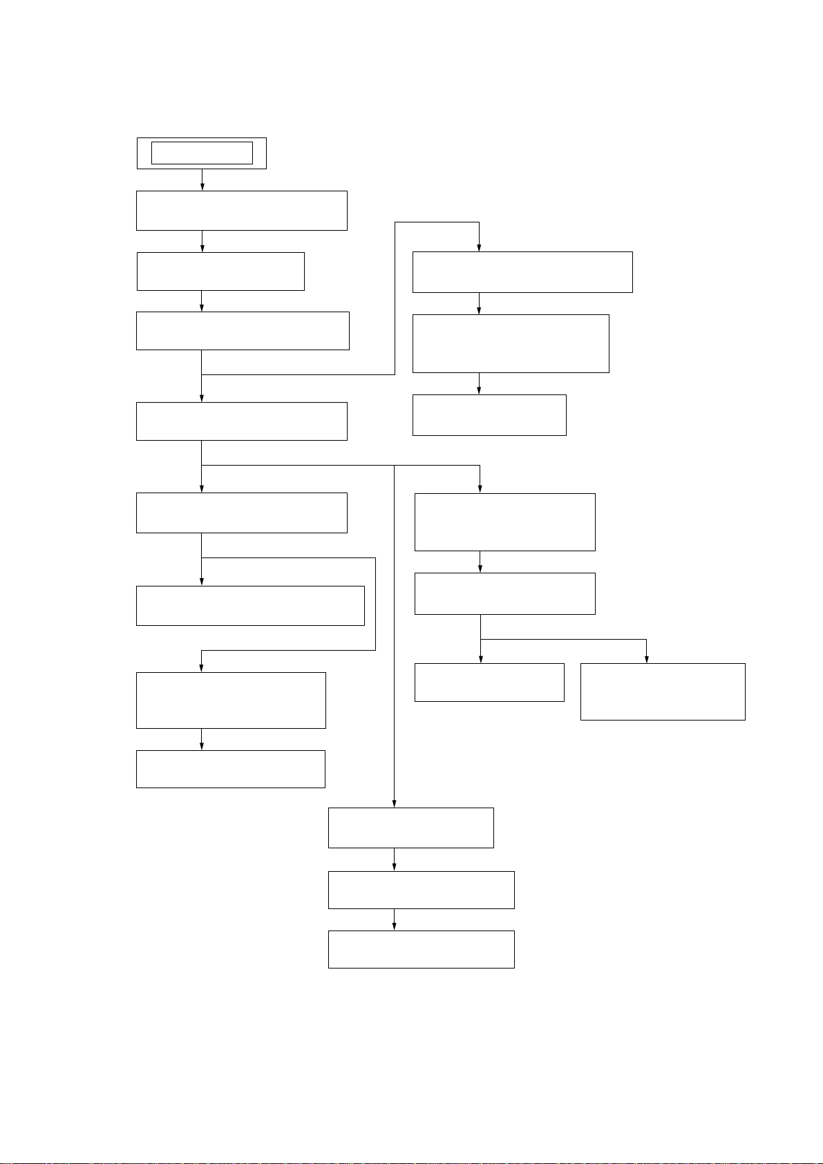
Note : Disassemble the unit in the order as shown below.
SET
2-1. CABINET STEEL CASE
(Page 10)
HCD-GNZ77D/GNZ88D
SECTION 2
DISASSEMBLY
2-2. LOADING PANEL
(Page 10)
2-3. FRONT PANEL SECTION
(Page 11)
2-4. DVD BLOCK SECTION
(Page 11)
2-5. BACK PANEL SECTION
(Page 12)
2-6. MAIN BOARD, ADC BOARD
(Page 12)
2-9. TAPE MECHANISM DECK
(Page 14)
2-10. HOLDER TC-R ASSY ,
HOLDER TC-L ASSY
(Page 14)
2-11. MIC BOARD
(Page 15)
2-12. KARAOKE BOARD,
VIDEO BOARD
(Page 15)
2-13. DMB15 BOARD
(Page 16)
2-7. SPEAKER BOARD,
S-MASTER BOARD
(Page 13)
2-8. POWER BOARD
(Page 13)
2-17. PICK-UP UNIT
(Page 18)
2-14. SENSOR BOARD
(Page 16)
2-15. MOTOR (TB) BOARD
(Page 17)
2-16. MOTOR (LD) BOARD
(Page 17)
2-18. SW BOARD,
DRIVER BOARD
(Page 18)
9

HCD-GNZ77D/GNZ88D
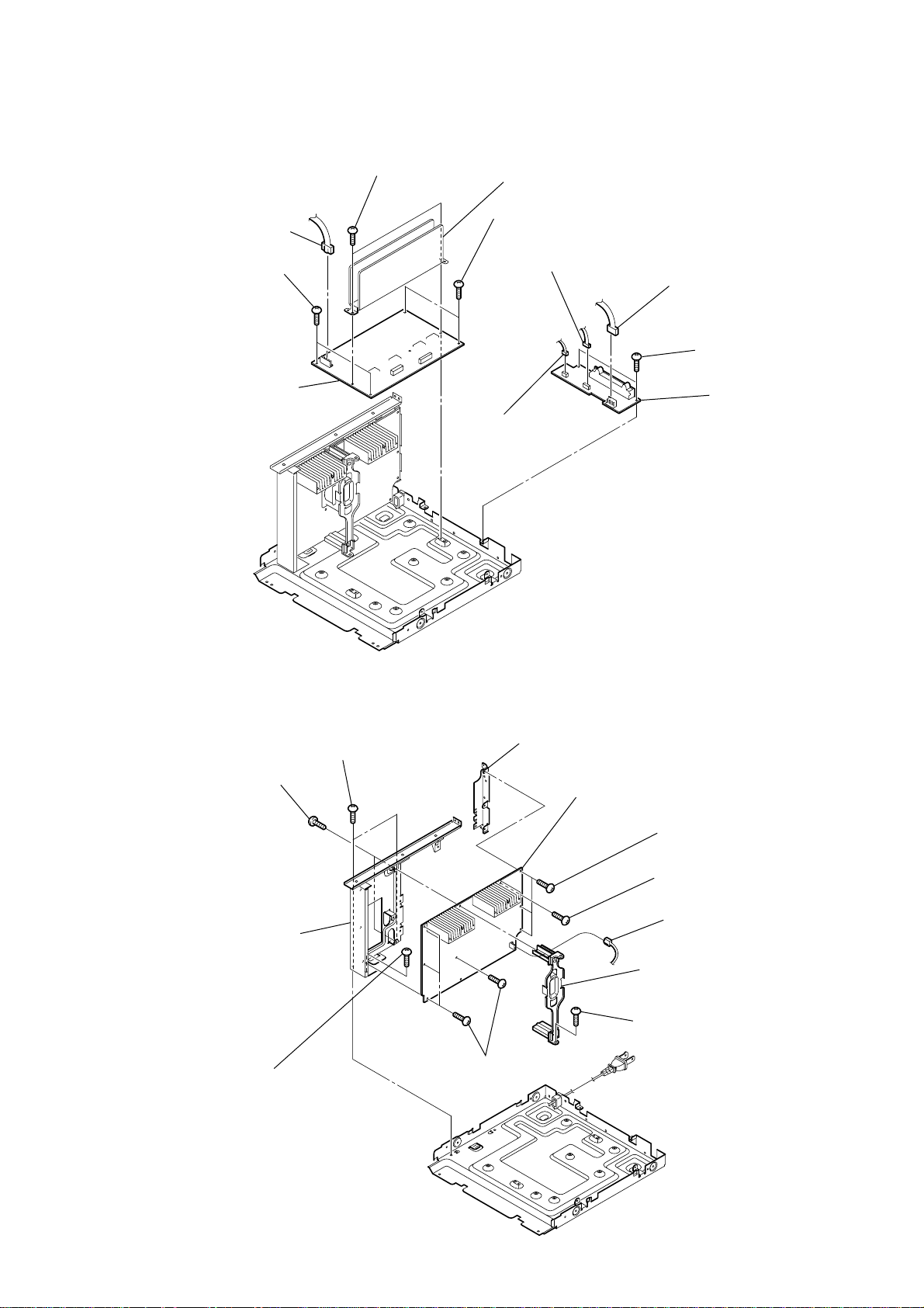
Note : Follow the disassembly procedure in the numerical order given.
2-1. CABINET STEEL CASE
4
screw
(case 3 TP2)
3
screw
(case 3 TP2)
0
cabinet steel case
8
9
8
1
screw
(case 3 TP2)
6
two screws (+BVTP 3
5
three screws
(+BVTP 3
7
two screws
(+BVTP 3
2
screw
(case 3 TP2)
×
×
×
8)
8)
8)
2-2. LOADING PANEL
CD mechanism deck (CDM74)
1
Turn the pulley to the direction of the arrow.
pulley
Front panel side
2
Pull-out the disc tray.
3
loading panel
10

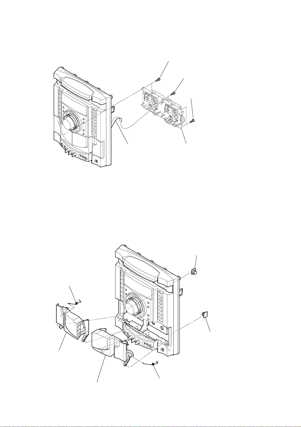
2-3. FRONT PANEL SECTION
7
screw
(tapping screw)
qa
CN503 (3P)
0
CN1967 (2P)
9
5
CN205 (11P)
HCD-GNZ77D/GNZ88D
qs
front panel section
four screws (+BVTP 3
6
2-4. DVD BLOCK SECTION
0
DVD block section
4
CN121 (3P)
8
3
CN131 (8P)
1
wire (flat type) (11 core)
(CN101)
2
×
8)
6
wire (flat type) (25 core)
(CN201)
7
wire (flat type) (13 core)
(CN301)
5
(+BVTP 3
screw
(tapping screw)
three
screws
×
8)
4
three
three
screws
screws
(+BVTP 3
3
(+BVTP 3
×
8)
×
8)
1
CN2000 (6P)
2
CN1880 (8P)
9
wire (flat type) (13 core)
(CN405)
8
wire (flat type) (19 core)
(CN521)
11

HCD-GNZ77D/GNZ88D
)
d
2-5. BACK PANEL SECTION
0
back panel section
3
two
screws
(+BVTP 3
(HCD-GNZ88D only)
×
8)
2
two
screws
(+BVTP 3
4
(+BVTP 3
×
screw
8)
×
8)
wire (flat type)
1
2-6. MAIN BOARD, ADC BOARD
4
two
screws
(+BVTT 3
(9 core)
×
6 (sumitite))
8
9
ADC board
9
CN580 (3P)
5
two
screws
(+BVTP 3
6
three
(+BVTP 3
7
three
8
MAIN boar
screws
(+BVTP 3
×
8)
screws
×
×
8)
8
12
1
CN501 (12P)
2
wire (flat type) (19 core)
3
CN812 (3P)
6
7
CN590 (7P)
5
two
screws
(+BVTP 3
×
8)
2-7. SPEAKER BOARD, S-MASTER BOARD
d
)
7
two
screws
6
CN502 (6P)
0
two
screws
(+BVTT 3
qa
S-MASTER board
×
6 (sumitite))
(+BVTT 3
×
6 (sumitite))
8
heat sink assy
9
two
screws
(+BVTT 3
2
3
CN1700 (2P)
×
6 (sumitite))
CN1601 (4P)
HCD-GNZ77D/GNZ88D
1
CN1500 (4P)
4
two
screws
(+BVTP 3
5
×
8)
SPEAKER boar
2-8. POWER BOARD (HCD-GNZ88D only)
2
two
screws
5
two
(tapping)
9
bracket assy
3
(+BVTT 3
screws
screw
(+BVTT 3
×
6 (sumitite))
×
6 (sumitite))
qa
bracket (SMPS-B5)
8
four
screws
(+BVTP 3
×
qs
8)
POWER board
0
(+BVTP 3
7
(tapping)
6
bracket assy
4
screw
(+BVTT 3
three
screws
screw
1
CN1100 (2P)
×
×
8)
6 (sumitite)
13
HCD-GNZ77D/GNZ88D
k
r
2-9. TAPE MECHANISM DECK
1
wire (flat type)
(11 core)
2
two
screws
(+BVTP 2.6 (3CR))
3
two
screws
(+BVTP 2.6 (3CR))
4
two
screws
(+BVTP 2.6 (3CR))
5
tape mechanism dec
2-10. HOLDER TC-R ASSY, HOLDER TC-L ASSY
6
spring (L)
5
holder TC-L assy
2
damper
1
dampe
14
3
holder TC-R assy
4
spring (R)

2-11. MIC BOARD
)
4
bracket (TC)
HCD-GNZ77D/GNZ88D
1
four
screws
(+BVTP 2.6 (3CR))
2
bracket (pivot)
5
MIC board
2-12. KARAOKE BOARD, VIDEO BOARD
7
CN401 (5P)
3
three
(+BVTP 3
screws
6
(CN1966)
×
8)
wire (flat type) (13 core)
9
VIDEO board
2
KARAOKE board
1
two
screws
(+BVTP 3
×
3
screw
(+BVTP 3
8)
8
two
screws
(+BVTP 3
×
8)
5
(HCD-GNZ88D only
×
8)
4
screw
(+BVTP 3
shield plate (video)
×
8)
15

HCD-GNZ77D/GNZ88D
)
2-13. DMB15 BOARD
9
screw
(+BVTP 3
×
0
cover (CDM)
8
two
8)
screws
(+BVTP 3
×
8)
7
bracket mediatek
6
(+BVTP 3
2-14. SENSOR BOARD
2
tray
screw
×
4
two
screws
(+BVTP 3
1
(+PTPWH M2.6)
6
(+PTPWH M2.6)
8)
×
8)
floating
floating
screw
8
screw
(+BTTP (M2.6))
screw
9
SENSOR board
0
CN731
(3P)
2
wire (flat type) (24 core
(CN101)
1
CN201 (6P)
5
DMB15 board
3
two
screws
(+BVTP 3
3
belt (table)
4
(+PTPWH M2.6)
×
8)
floating
5
pulley (table)
screw
16
7
gear (geneva)
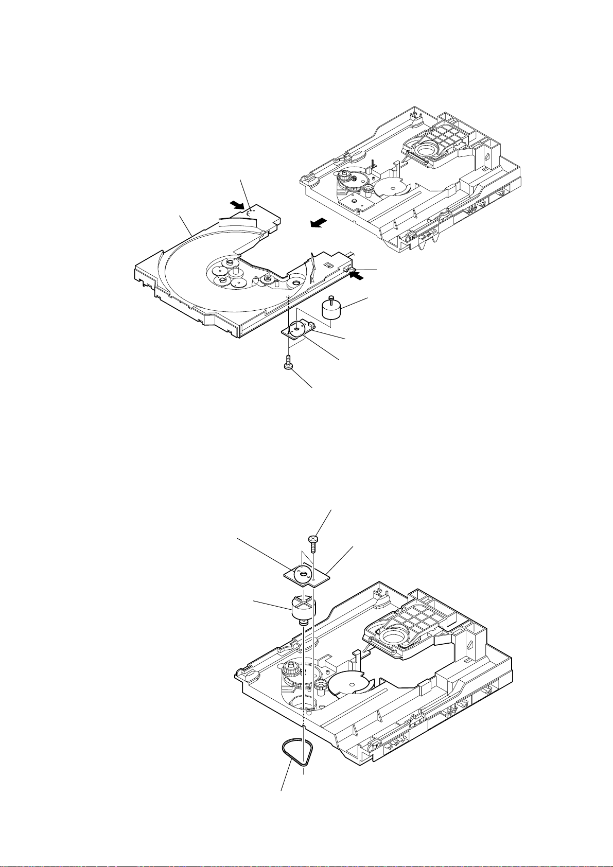
2-15. MOTOR (TB) BOARD
table assy
2
stopper
1
2
stopper
6
table motor assy (M741)
HCD-GNZ77D/GNZ88D
2-16. MOTOR (LD) BOARD
4
Remove the two solders of motor.
5
loading motor assy (M751)
4
MOTOR (TB) board
5
Remove the two solders of motor.
3
two
screws
(+BTTP (M2.6))
2
two
screws
(+BTTP (M2.6))
3
MOTOR (LD) board
1
belt (loading)
17

HCD-GNZ77D/GNZ88D
)
d
2-17. PICK-UP UNIT
3
two insulator screws
6
pick-up unit
5
two insulators
2
two insulator screws
4
two insulators
2-18. SW BOARD, DRIVER BOARD
2
SW board
7
holder (310)
7
CN702 (5 core)
4
CN703 (4P)
6
DRIVER boar
1
floating
(+PTPWH M2.6
screw
18
3
1
screw
(+BTTP (M2.6))
CN704 (2P)
5
two
screws
(+BTTP (M2.6))

SECTION 3
TEST MODE
HCD-GNZ77D/GNZ88D
[PANEL TEST MODE]
•This mode is used to check the fluorescent indicator tube, LEDs,
keys, VOLUME jog, model, destination, software version and
VACS level.
Procedure:
1. Press x button, [ILLUMINATION] button and [DISC 2] button
simultaneously.
2. All LEDs and segments in fluorescent indicator tube are lighted
up. All LEDs are lighted up in red color where the SUB
WOOFER ON/OFF LED is lighted up in green color.
3. When you want to enter to the software version dispaly mode,
press [DISC 1] button. The model information appears on the
fluorescent indicator tube. Press [DISC 1] button again to view
the destination information.
4. Each time [DISC 1] button is pressed, the display changes from
MC version, SYS version, UI version, DVD version, CDMA
version, CDMB version, ST version, TA version, TM version,
TC version in this order, and returns to the model ver sion display .
5. When [DISC 3] button is pressed while the version numbers are
being displayed except model and destination, the date of the
software creation appears. When [DISC 3] button is pressed
again, the display returns to the software version display . When
[DISC 1] button is pressed while the date of the software creation
is being displayed, the date of the software creation is displayed
in the same order of software version display.
6. Press [DISC 2] button, the key check mode is activated.
7. In the key check mode, the fluorescent indicator tube displays
“K 0 V0”.
Turn the [OPERATIONAL DIAL] clockwise; “K” value increases
by one. Turn the [OPERATIONAL DIAL] counterclockwise; “K”
value increases by one. Each time a button is pressed, “K” v alue
increases. Press other keys on main unit to check whether the
key is detected. However, once a button has been pressed, it is
no longer taken into account.
“V” value increases in the manner of 0, 1, 2, 3 ... if [VOLUME]
knob is turned clockwise, or it decreases in the manner of 0, 9,
8, 7 ... if [VOLUME] knob is turned counterclockwise.
8. When [DISC 3] button is pressed after all LEDs and segments in
fluorescent indicator tube light up, the fluorescent indicator tube
displays “V A CS A”. A is VACS lev el which is triggered by signal
level.
9. When [DISC SKIP/EX-CHANGE] button is pressed after all LEDs
and segments in fluorescent indicator tube light up, alternate
segments in fluorescent indicator tube would light up. If you
press [DISC SKIP/EX-CHANGE] button again, another half of
alternate segments in fluorescent indicator tube would light up.
When [DISC SKIP/EX-CHANGE] button is pressed again, all
segments lights off. Press [DISC SKIP/EX-CHANGE] button again
would cause all segments lights up.
10. To release from this mode, press three buttons in the same
manner as step 1, or disconnect the power cord.
[COMMON TEST MODE]
•This mode is used to check operations of the respective sections
of Amplifier and Tape.
Procedure:
•To enter Common Test Mode
1. Press x button, [ILLUMINATION] button and [DISC 3] button
simultaneously.
2. The D VD ring indicators and the line below D VD ring indicator
flash synchronously on the fluorescent indicator tube. The
function is changed to TV where the function is changed to
DVD.
• Check of Amplifier
1. Press [EQ BAND/MEMORY] button repeatedly until a message
“GEQ MAX” appears on the fluorescent indicator tube. GEQ
increases to its maximum.
2. Press [EQ BAND/MEMORY] button repeatedly until a message
“GEQ MIN” appears on the fluorescent indicator tube. GEQ
decreases to its minimum.
3. Press [EQ BAND/MEMORY] button repeatedly until a message
“GEQ FLAT” appears on the fluorescent indicator tube. GEQ
is set to flat.
4. When the [VOLUME] knob is turned clockwise even slightly,
the sound volume increases to its maximum and a message
“VOLUME MAX” appears on the fluorescent indicator tube.
5. When the [VOLUME] knob is turned counterclockwise even
slightly, the sound volume decreases to its minimum and a
message “VOLUME MIN” appears on the fluorescent indicator
tube.
•Tape function
1. When a tape is inserted in Deck B and recording is started, the
function is changed to TV automatically . The function is change
to DVD automatically when a tape is inserted in Deck B and
recording is started. When [CD SYNC] button is pressed during
recording in function, ALC (Automatic Logic Control) is turned
on.
2. During recording, press m button will stop the recording and
the function is changed to TAPE B and rewind the tape in Deck
B until the recording start position and playback of the tape in
Deck B is started. If the [REC PAUSE/START] button is pressed
for a pause and pressed again to resume recording during
recording time, when the tape is rewind, the tape will be rewind
until the position where the pause is applied.
•To release from Common Test mode
1. To release from this mode, press
2. The cold reset is enforced at the same time.
[COLD RESET]
• The cold reset clears all data including preset data stored in the
RAM to initial conditions. Execute this mode when returning
the set to the customer.
Procedure:
1. Press ?/1 button to turn on the system.
2. Press x button, [ILLUMINATION] button, and ?/1 button
simultaneously.
3. The message “COLD RESET” appears on the fluorescent
indicator tube. Then, the fluorescent indicator tube becomes
blank for a while, and the system is reset.
[VACS ON/OFF]
•This mode is used to switch on and off the VACS (Variable
Attenuation Control System).
Procedure:
1. Press ?/1 button to turn on the system.
2. Press x button, [DIRECTION] button and [DISC 1]
simultaneously. The message “VACS OFF” or “VACS ON”
appears on the fluorescent indicator tube.
[TUNER STEP CHANGE]
•The step interval of AM c hannels can be toggled between 9 kHz
and 10 kHz. This mode is not available for Saudi Arabia and
Russia models.
?/1 button.
19

HCD-GNZ77D/GNZ88D
Procedure:
1. Press ?/1 button to turn on the system.
2. Press [TUNER/BAND] button repeatedly to select the “AM”.
3. Press
4. Press [ILLUMINATION] button and
[DVD SHIP MODE (WITH MEMORY CLEAR)]
•This mode moves the optical pick-up to the position durable to
Procedure:
1. Press ?/1 button to turn on the system.
2. Select DVD function.
3. Press x button, [DIRECTION] button and ?/1 button
4. After the “STANDBY” blinking display finishes, a message
[DVD SHIP MODE (WITHOUT MEMORY CLEAR)]
•This mode moves the optical pick-up to the position durable to
Procedure:
1. Press ?/1 button to turn on the system.
2. Select DVD function.
3. Press [DVD] button and
4. After the “STANDBY” blinking display finishes, a message
[DVD TRAY LOCK MODE]
•This mode let you lock the disc tray. When this mode is
Procedure:
1. Press ?/1 button to turn on the system.
2. Select DVD function.
3. Press x button and [OPEN/CLOSE] button simultaneously and
[TCM OFFLINE MODE]
•This mode prevents the system from turning off automatically
Procedure:
1. When the system is turned off, press [EQ BAND/MEMORY]
2. The message “TCM OFFLINE” will appears on the fluorescent
•To release from TCM Offline Mode
?/1 button to turn off the system.
?/1 button simultaneously.
The system will turn on automatically. The message “AM 9K
STEP” or “AM 10K STEP” appears on the fluorescent indicator
tube and thus the channel step is changed.
vibration and clears all data including preset data stored in the
RAM to initial conditions. Use this mode when returning the
set to the customer after repair.
simultaneously during “DVD NO DISC” condition. The system
will turn off automatically.
“MECHA LOCK” appears on the fluorescent indicator tube and
the DVD ship mode is set.
vibration. Use this mode when returning the set to the customer
after repair.
?/1 button simultaneously during “DVD
NO DISC” condition. The system will turn off automatically.
“MECHA LOCK” appears on the fluorescent indicator tube and
the DVD ship mode is set.
activated, the disc tray will not open when [OPEN/CLOSE]
button or [DISC SKIP/EX-CHANGE] button is pressed. The
message “LOCKED” will appears on the fluorescent indicator
tube.
hold down until “LOCKED” or “UNLOCKED” appears on the
fluorescent indicator tube (around 5 seconds).
when TCM is not connected. Therefore, measurements can be
done even when TCM is not connected during production.
button, [TAPE A/B] button and ?/1 button simultaneously. The
system will turn on automatically.
indicator tube.
To release from this mode, perform “COLD RESET” or turn off
the power supply.
[TV/SAT SWITCHING]
•This mode let you switch from TV to SAT and vice-versa.
Procedure:
1. Press
2. Select TV function.
3. Press [TV/SAT] button and ?/1 button simultaneously. The
[DVD COLOR SYSTEM]
• This mode let you change the color system of the video output
Procedure:
1. Press ?/1 button to turn on the system.
2. Select DVD function.
3. Press ?/1 button again to turn off the system.
4. Press X button and ?/1 button simultaneously. The system
[REMOTE DISABLE MODE]
• This mode let you disable the remote commander reception.
Procedure:
1. Press
2. Press x button, [DIRECTION] button and [DISC 3] button
[PROGRESSIVE]
• This mode let you change the format of the video output from
Procedure:
1. Press ?/1 button to turn on the system.
2. Press [DVD] button and [DISPLAY] button simultaneously. “P
[MTK FIRMWARE DISPLAY]
•This mode is used to display the MTK firmware version.
Procedure:
1. Press ?/1 button to turn on the system.
2. Press [DVD] button to switch to DVD function.
3. Press ?/1 button again to turn off the system.
4. Press x button and ?/1 button. The system turns on
5. The version of MTK firmware appears on the TV screen.
[DVD SERVICE MODE]
•This mode let you make diagnosis and adjustment easily by
?/1 button to turn on the system.
function will change to SAT. Press the same buttons again to
change from SAT to TV.
from P AL to NTSC or vice-versa. This mode is not av ailable for
Latin American and Russian models.
will turn on automatically.
The message “COLOR PAL” or “COLOR NTSC” appears on
the fluorescent indicator tube.
When this mode is activated, the system will not response if the
button on the remote commander is pressed. The message “RM
DISABLE” appears on the fluorescent indicator tube.
This mode is essential for conducting test and repairing when
no interruption from the other remote commander is expected.
This mode is cancelled automatically when the system is turned
off.
?/1 button to turn on the system.
simultaneously until “SIRCS ON” or “SIRCS OFF” appears on
the fluorescent indicator tube.
the COMPONENT OUT jacks among PROGRESSIVE AUTO,
PROGRESSIVE VIDEO and INTERLACE.
AUTO” or “P VIDEO” or “INTERLACE” appears on the
fluorescent indicator tube.
automatically.
using the remote commander and the TV. The instructions,
diagnostic results, etc. are given on the on-screen display.
20

HCD-GNZ77D/GNZ88D
Ver. 1.3
• TEST DISC LIST
Be sure to use the DVD disc that matches the signal standards of
your region.
• CD
YEDS-18 (Part No.: 3-702-101-01)
PATD-012 (Part No.: 4-225-203-01)
• DVD SL (Single Layer)
NTSC : HLX-503 (Part No.: J-6090-069-A)
HLX-504 (Part No.: J-6090-088-A)
PAL:HLX-506 (Part No.: J-6090-077-A)
• DVD DL (Dual Layer)
NTSC : HLX-501 (Part No.: J-6090-071-A)
HLX-505 (Part No.: J-6090-089-A)
PAL:HLX-507 (Part No.: J-6090-078-A)
• Procedure to enter to DVD Service Mode:
1. Press ?/1 button to turn on the system.
2. Select DVD function.
3. Press x button and [OPEN/CLOSE] button simultaneously and
then turn the [VOLUME] knob clockwise.
4. The message “SERVICE IN” appears on the fluorescent
indicator tube and the Top Menu of Remocon Diagnosis Menu
appears on the on-screen display on the TV. The model name
and revision number is displayed at the bottom of the on-screen
display.
Remocon Diagnosis Menu
0. External Chip Check
1. Servo Parameter Check
2. Drive Manual Operation
3. Emergency History
4. Version Information
Model Name : GML6DS_ME
IF-con : V
Syscon : Ver.
er. 01.00 (0000)
0.302
5. To execute each function, press its number by using numeric
button on the remote commander.
6. To release from this mode, press ?/1 button to turn off the
system.
• Execute IOP Measurement
In order to execute IOP measurement, the following standard
procedures must be followed.
1. From the Top Menu of Remocon Diagnosis Menu, select “2.
Drive Manual Operation” by pressing the [2] button on the
remote commander. The following screen appears on the onscreen display.
Drive Manual Operation
1. Servo Control
2. Track/Layer Jump
3. Manual Adjustment
4. Mecha test Mode
5. MIRR time Adjust
0. Return to Top Menu
Manual Adjust
1. Track Balance Adjust:
2. Track Gain Adjust:
3. Focus Balance Adjust:
4. Focus Gain Adjust:
5. Eg Boost Adjust:
6. Iop:
7. TRV. Level:
8. S curve(FE) Level:
9. RFL(PI) Level:
0. MIRR Time:
O o Change Value
RETURN Return to previous menu
3. Select “6. Iop:” by pressing [6] button on the remote commander .
4. Wait until a hexadecimal number appears in the on-screen
display as below:
Manual Adjust
1. Track Balance Adjust:
2. Track Gain Adjust:
3. Focus Balance Adjust:
4. Focus Gain Adjust:
5. Eg Boost Adjust:
6. Iop. ED:
7. TRV. Level:
8. S curve(FE) Level:
9. RFL(PI) Level:
0. MIRR Time:
O o Change Value
RETURN Return to previous menu
5. Con vert data from hexadecimal to decimal by using con version
table.
6. Please find the label on the rear of the BU (Base Unit).
The default IOP value is written in the label.
7. Subtract between these two values.
8. If the remainder is smaller than 93 (decimal), then it is OK.
However if the v alue is higher than 93, then the BU is defectiv e
and need to be change.
9. Press [RETURN] button on the remote commander to return to
previous menu.
10. Press [0] button on the remote commander to return to the Top
Menu of Remocon Diagnosis Menu.
11. Press ?/1 button to turn off the system.
• Check Emergency History
To check the emergency history, please follow the following
procedure.
1. From the Top Menu of Remocon Diagnosis Menu, select “3.
Emergency History” by pressing the [3] button on the remote
commander. The following screen appears on the on-screen
display.
2. Select “3. Manual Adjustment” by pressing the [3] button on
the remote commander. The following screen appears on the
on-screen display.
21

HCD-GNZ77D/GNZ88D
Ver. 1.3
Emg.History Check
Laser Hours CD 999h 59min
1. 01 05 04 04
00 00 00 00 00 00 23 45
2. 02 02 01 01 00 A9 4B 00
00 00 00 00 00 00 23 45
Next Next Page Prev Prev Page
O Return to Top Menu
DVD 999h 59min
00 92 46 00
2. You can check the total time when the laser is turned on during
playback of DVD and CD from the above menu. The maximum
time, which can be displayed are 999h 59min.
3. You can check the error code of latest 10 emergency history
from the above menu. To view the previous or next page of
emergency history, press . or > on the remote
commander. The error code consists of
• Error Code
Example of Error code
1. 01 05 04 04 00 92 46 00
00 00 00 00 00 00 23 45
The meaning of error code is as below:
01: Communication error (No reply from syscon)
02: Syscon hung up
03: Power OFF request when syscon hung up
19: Thermal shutdown
24: MoveSledHome error
25: Mechanical move error (5 Changer)
26: Mechanical move stack error
30: DC motor adjustment error
31: DPD offset adjustment error
32: TE balance adjustment error
33: TE sensor adjustment error
34: TE loop gain adjustment error
35: FE loop gain adjustment error
36: Bad jitter after adjustment
40: Focus NG
42: Focus layer jump NG
52: Open kick spindle error
51: Spindle stop error
60: Focus on error
61: Seek fail error
62: Read Q data/ID error
70: Lead in data read fail
71: TOC read time out (CD)
80: Can’t buffering
81: Unknown media type
•Time of error code
This is the laser time when an error occurred.
Example of Error code
1. 01 05 04 04 00 92 46 00
00 00 00 00 00 00 23 45
To clear the Laser Hour
Press [DISPLAY] button and then press [CLEAR] button. The data
for both CD and DVD data are reset.
Emg.History Check
Laser Hours CD 0h 0min
1. 01 05 04 04
00 00 00 00 00 00 23 45
2. 02 02 01 01 00 A9 4B 00
00 00 00 00 00 00 23 45
Next Next Page Prev Prev Page
O Return to Top Menu
DVD 0h 0min
00 92 46 00
To clear the Emergency History
Press [TOP MENU] button and then press [CLEAR] button. The error
code for all emergency history would be reset.
Emg.History Check
Laser Hours CD 999h 59min
1. 00 00 00 00
00 00 00 00 00 00 00 00
2. 00 00 00 00 00 00 00 00
00 00 00 00 00 00 00 00
Next Next Page Prev Prev Page
O Return to Top Menu
DVD 999h 59min
00 00 00 00
To clear the Initialize Setup Data
Press [MENU] button and then press [CLEAR] button on the remote
commander.
Emg.History Check
Laser Hours CD 999h 59min
Initialize setup data...
DVD 999h 59min
• Parameter of error code
This is the detail of error code.
Example of Error code
1. 01 05 04 04 00 92 46 00
00 00 00 00 00 00 23 45
22
Next Next Page Prev Prev Page
O Return to Top Menu
HCD-GNZ77D/GNZ88D
SECTION 4
Ver. 1.3
MECHANICAL ADJUSTMENTS
To return to the Top Menu of Remocon Diagnosis Menu
Press [0] button on the remote commander.
• Check Version Information
To check the version information, please follow the following
procedure.
1. From the Top Menu of Remocon Diagnosis Menu, select “4.
Version Information” by pressing the [4] button on the remote
commander. The following screen appears on the on-screen
display.
Version information
Firm (Main) : Ver. xxxxx
Firm (Sub) : xxxxx
RISC : xxxxx
8032 : xxxxx
Audio DSP : xxxxx
Servo DSP : xxxxx
O Return to Top Menu
To return to the Top Menu of Remocon Diagnosis Menu, press
[0] on the remote commander.
Precaution
1. Clean the following parts with a denatured alcohol-moistened
swab:
record/playback heads pinch rollers
erase head rubber belts
capstan idlers
2. Demagnetize the record/playback head with a head
demagnetizer.
3. Do not use a magnetized screwdriver for the adjustments.
4. After the adjustments, apply suitable locking compound to the
parts adjusted.
5. The adjustments should be performed with the rated power
supply voltage unless otherwise noted.
Torque Measurement
Mode
FWD
FWD
back tension
REV
REV
back tension
FF/REW
FWD tension
REV tension
Torque meter
CQ-102C
CQ-102C
CQ-102RC
CQ-102RC
CQ-201B
CQ-403A
CQ-403R
Meter reading
3.06 N • m to 6.96 N • m
31 to 71 g • cm
(0.43 – 0.98 oz • inch)
0.19 N • m to 0.58 N • m
2 to 6 g • cm
(0.02 – 0.08 oz • inch)
3.06 N • m to 6.96 N • m
31 to 71 g • cm
(0.43 – 0.98 oz • inch)
0.19 N • m to 0.58 N • m
2 to 6 g • cm
(0.02 – 0.08 oz • inch)
6.96 N • m to 14.02 N • m
71 to 143 g • cm
(0.98 – 1.99 oz • inch)
9.80 N • m
100 g or more
(3.53 oz or more)
9.80 N • m
100 g or more
(3.53 oz or more)
23
HCD-GNZ77D/GNZ88D
)
Ver. 1.3
SECTION 5
ELECTRICAL ADJUSTMENTS
DVD SECTION
When the optical pick-up assy is replaced, perform the “Execute
IOP Measurement”.
Execute IOP Measurement (See page 21)
[TEST DISC LIST]
Be sure to use the DVD disc that matches the signal standards of
your region.
• CD
YEDS-18 (Part No.: 3-702-101-01)
PATD-012 (Part No.: 4-225-203-01)
• DVD SL (Single Layer)
NTSC : HLX-503 (Part No.: J-6090-069-A)
HLX-504 (Part No.: J-6090-088-A)
PAL : HLX-506 (Part No.: J-6090-077-A)
• DVD DL (Dual Layer)
NTSC : HLX-501 (Part No.: J-6090-071-A)
HLX-505 (Part No.: J-6090-089-A)
PAL : HLX-507 (Part No.: J-6090-078-A)
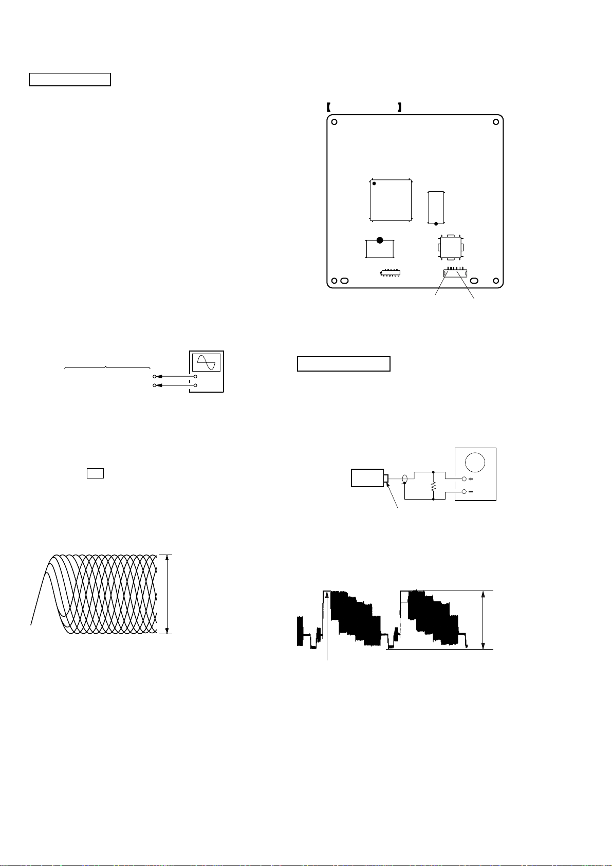
[RFMON Level Check]
Connection:
oscilloscope
DMB15 board
CN105 pin 6 (RFMON)
CN105 pin
3
(GND)
Procedure:
1. Connect an oscilloscope to CN105 pin 6 (RFMON) and
CN105 pin 3 (GND) on the DMB15 board.
2. Turn the power on.
3. Set the test disc (refer to the TEST DISC LIST) on the tray
and press H button to playback.
4. Confirm that oscilloscope waveform is clear and check
RFMON signal level is correct or not.
Note: A clear RFMON signal waveform means that the shape “◊” can be
clearly distinguished at the center of the waveform.
+
–
Checking Location: DMB15 board (Side A)
IC101
(SIDE A)
IC104
IC102
IC201
16
CN105
CN105 pin 3 (GND
DMB15 BOARD
CN106
CN105 pin 6 (RFMON)
VIDEO SECTION
Video Level Check (VIDEO BOARD)
Purpose
This adjustment is made to satisfy the NTSC standard, and if not
adjusted correctly, the brightness will be too large or small.
oscilloscope
75
Ω
set
J1902
VIDEO OUTPUT
RFMON signal waveform
VOLT/DIV: 200 mV
TIME/DIV: 500 ns
level: 0.58 ± 1.23 Vp-p (DVD)
0.57 ± 1.1 Vp-p (CD)
Procedure:
1. Connect oscilloscope to VIDEO output.
2. Load a DVD reference disc playback.
3. Check the video signal level is 1.00±0.07Vp-p.
1.00 ± 0.07 Vp-p
(WHITE 100%)
24

HCD-GNZ77D/GNZ88D
r
e
DECK SECTION
0 dB=0.775 V
1. Demagnetize the record/playback head with a head
demagnetizer.
2. Do not use a magnetized screwdriver for the adjustments.
3. After the adjustments, apply suitable locking compound to the
parts adjust.
4. The adjustments should be performed with the rated power
supply voltage unless otherwise noted.
5. The adjustments should be performed in the order giv en in this
service manual. (As a general rule, playback circuit adjustment
should be completed before performing recording circuit
adjustment.)
6. The adjustments should be performed for both L-CH and RCH.
7. Switches and controls should be set as follows unless otherwise
specified.
•Test Tape
Tape Signal Used for
P-4-A063 6.3 kHz, –10 dB Azimuth Adjustment
Record/Playback Head Azimuth Adjustment
DECK A DECK B
Note: Perform this adjustments for both decks
Procedure:
1. Mode: Playback
3. Mode: Playback
test tape
P-4-A063
(6.3 kHz, –10 dB)
L-CH
MAIN
board
IC101
R-CH
waveform of oscilloscope
in phase 45°90°135°180
pin 28
pin 36
L
R
pin 37
good
oscilloscop
V
wrong
H
°
4. After the adjustments, apply suitable locking compound to the
pats adjusted.
Adjustment Location: Playback Head (Deck A).
Record/Playback/Erase Head (Deck B).
test tape
P-4-A063
(6.3 kHz, –10 dB)
MAIN board
IC101
Pin 28 (L-CH)
Pin 37 (R-CH)
set
MAIN board
IC101
Pin 36 (GND)
level mete
+
–
2. T urn the adjustment screw and chec k output peaks. If the peaks
do not match for L-CH and R-CH, turn the adjustment screw
so that outputs match within 1dB of peak.
output
level
within
1dB
L-CH
peak
R-CH
peak
within
1dB
screw
position
L-CH
peak
screw
position
R-CH
peak
forward
forward
25

HCD-GNZ77D/GNZ88D
MEMO
26
SECTION 6
DIAGRAMS
6-1. BLOCK DIAGRAM — RF/SERVO SECTION —
HCD-GNZ77D/GNZ88D
DETECTOR
OPTICAL PICK-UP
BLOCK
LASER
DIODE
(FOR CD)
LASER
DIODE
(FOR DVD)
2AXIS
DEVICE
FOCUS/
TRACKING
COIL
MM
SLED
MM
SPINDLE
RF
LIMIT
CD LD
PD
DVD LD
VR650
VR780
MSW
FCS+
FCS–
TRK+
TRK–
SL–
SL+
SP+
SP–
A
B
C
D
F
E
CBA
D
AUTOMATIC POWER
CONTROL (FOR CD)
Q102 (1/2)
AUTOMATIC POWER
CONTROL (FOR DVD)
Q102 (2/2)
VOLUME CONTROL
Q101, Q103
L
DVDRFIP
6
2
DVDA
3
DVDB
4
DVDC
5
DVDD
19
TPI
18
TNI
A
8
NA
B
9
NB
C
10
MC
D
11
MD
176
LI M SW
23
LD01
20
MD12
MD11
21
LD02
22
MSW
50
42
41
36 48
37 1
35 3
34 4
VCC
32
30
29
27
28
46
47
OSP
252 253
FOCUS/TRACKING COIL DRIVER,
SPINDLE, SLED MOTOR DRIVER
IC201
BUFFER
FOCUS COIL
DRIVE
TRACKING COIL
DRIVE
SLED MOTOR
DRIVE
SPINDLE MOTOR
DRIVE
BUFFER
OSN
CD/DVD RF AMP,
FOCUS/TRACKING ERROR AMP
DVD SYSTEM PROCESSOR
DIGITAL SERVO PROCESSOR
43
10
13
40
45
19
20
22
21
V1P4
FOO
TRO
FMO
DMO
IC102(1/2)
V1P4
FMO
FOO
DMO
TRO
38
42
37
41
30
40
47
211
210
170
FMO
FOO
DMO
TRO
V REFO
IOPMON
SPFG
MUTE123
MUTE
TSDM
PRST
IFCK
IFSDO
IFSDI
XIFCS
IFBSY
KRMOD/HSYNC
MIC/VSYNC
• Signal Path
: CD PLAY
: DVD PLAY
: SACD PLAY
110
99
98
101
100
105
207
205
26
MTK_RESET
33
MTK_CLK
32
MTK_SOD
31
MTK_SIO
27
MTK_XIFCK
28
MTK BUSY
24
KRMOD
25
MIC STATUS
SYSTEM
CONTROL
IC401(1/4)
HCD-GNZ77D/GNZ88D
27 27
HCD-GNZ77D/GNZ88D
6-2. BLOCK DIAGRAM — VIDEO SECTION —
YUV3
YUV2
YUV1
YUV4
YUV5
YUV6
WIDE
DSEL
VOICE
SMSCK
ASDAT0
ASDAT1
ASDAT2
ASDAT4
XRST
ACLK
ABCK
ALRCK
SDPIF
198
196
194
200
202
203
49
48
206
208
217
218
219
222
220
215
214
213
225
V
C
Y
YG
CR/B
CB/R
WIDE
DSEL
VOICE
SCORE
B
(Page 29)
A
(Page 29)
MAIN
SECTION
MAIN
SECTION
14
SDTI1
15
SDTI2
16
SDTI3
13
SDTI4
8
PDN
10
MCLK
9
BICK
17
LRCK
19
SCL
20
SDA
DIGITAL
OPTICAL
TRANSMITTER
IC508
D/A CONVERTER
IC301
(SW)
(DMIXL)
GNZ77D
DVD
DIGITAL
OUT
(SL)
(FC)
(FL)
LOUT2+
LOUT2–
LOUT3+
LOUT3–
ROUT3+
ROUT3–
LOUT4+
LOUT4–
LOUT1+
LOUT1–
GNZ77D
IC3731
46
45
IC3751 (1/2)
42
41
IC3751 (2/2)
40
39
IC3771
38
37
IC3711
2
1
SURROUND L
CENTER
SUBWOOFER
DOWNMIX L
FRONT L
C
(Page 29)
MAIN
SECTION
• Signal Path
: AUDIO
: VIDEO
: COMPONENT VIDEO
: DIGITAL
X101
27MHz
229
XTALI
XTALO
228
SCL
SDA
102
103
6 5
SCL
SDA
EEPROM
IC103
DVD SYSTEM PROCESSOR
IC102(2/2)
AD0 – AD7
81-84,86-88,91
HD0 – HD7 A0 – A21
DATA & ADDRESS BUS
DATA & ADDRESS BUS
HD0 – HD7
29,31,33,35,38,40,42,44 25-16, 10 -1, 48
DQ0 – DQ7
HIGHA0-7
IOA0-7, IOA18-IOA21
A16, A17
53-61, 67-72, 74-76,
78, 89, 92, 93
A0
A0 – A19DQ15/A-1
FLASH ROM
IC101
A1-A21
IOCS
IOWA
IOUE
77
79
66
CEWEOE
2,4,5,7,8,10,11,13,42,44,45,47,48,50,51,53
CE
OE
WE
2645
28OE11
CE
WE
RD0 – RD15
125-123, 121, 120, 118,
117, 115, 135, 133-128, 126
RD0 – RD15
RA0 – RA11
146, 147, 149-151,
158-160, 162, 164-166
22-26,
29-35
RA0 – RA11
SDRAM
IC104
RCLK
RCS
RWE
RAS
BA0
BA1
143
20
142
145 156 113 137 157
38
19
21
BS0
BS1
DRCLK
138
RCS
CAS
140
139
16
18
17
CAS
RAS
RWE
15
DQM0
39
DQM0
DQM1
37
DQM1
CKE
DRCKE
HCD-GNZ77D/GNZ88D
2828

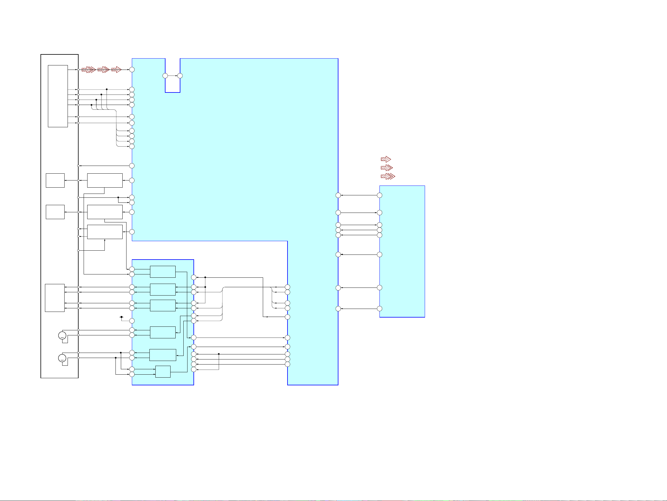
6-3. BLOCK DIAGRAM — MAIN SECTION —
CENTER
C
ECHO AMP
IC1400
Q107–109
SUBWOOFER
SURROUND L
FRONT L
DOWNMIX L
5VOL1
6VOL2
7VO 3
29POOUT
21MCO
Q113,114
BIAS OSC
Q112
CAP CONTROL
Q120,121
B TRG CONTROL
Q118,119
A TRG CONTROL
Q122,123
J1402
VIDEO
INPUT
ANTENNA
J501
TV/SAT IN
J1400
MIC 1
J1450
MIC 2
HRPE901
FM 75Ω
COAXIAL
AM
VIDEO
AUDIO
HP901
PB
HEAD
REC/PB
HEAD
ERASE
HEAD
MECHANISM
BLOCK
REC(REV)
REC(FWD)
CAP M+
B TRGM+
A TRGM+
L
R
L
R
(DECK A)
(DECK B)
TAPE
DECK
B SHUT
A SHUT
A HALF
B HALF
J501
J1402
TU901
R-CH
R-CH
Q154,
155
R-CH
R–CH
R–CH
5LCH
3RCH
4+9V
8DO
6DI
7CL
9CE
1TUNED
DIN
DOUT
CLK
CE
TUNED
VIDEO
SECTION
(Page 28)
R–CH
ST A+9V
T101
15 MIC1P
16 MIC2P
MUTE CONTROL
MUTE
Q285
RV1401
MIC2
LEVLE
RV1401
ECHO LEVEL
MIC AMP
IC1401
BIAS+9V
MUTE
MUTE
Q235
Q236
RV1401
MIC1
LEVLE
MUTE
Q166
MUTE CONTROL
Q110,111
AUDIO
SECTION
(Page 30)
MUTE
Q238
MUTE CONTROL
D
MUTE
Q237
MUTE
Q175
Q301,302
NSP MUTE
SOFT MUTE
DVD/CD MUTE
INIT
CONTROL
Q307,308
REC/PB AMP,
SOUND CONTROL
IC101
57 FRONT
4
DVD/CD
TU–LCH
3
5
LINE
2
VIDEO
59
MIC
75
PB A
76
PB B
17
REC
34
CLK
35
DATA
37
DIN
39
DOUT
38
CLK
36
40
34
83
84
23
90
89
63
91
20
21
18
19
17
12
10
ST
CE
TUNED
DVD A MUTE
DATA
CLK
MIC DETECT
B SHUT
A SHUT
A HALF
B HALF
SIGNAL IN/OUT CONTROL
7
REC MUTE
REC BIAS
TC REALY
CAMP CNT
B TRIG
A TRIG
SM INIT
9
SM NSP MUTING
SM SOFT MUTING
SURR CHANNEL
SYSTEM
CONTROL
IC401 (3/4)
IC403
29 5VRSW
23 12TONE L
42TONE R
28FRONT L
37FRONT R
26F/B
7MUSIC L+R
53L+R LIGHTING
SW CHANNEL
SELECT
SELECT
R–CH
R–CH
DBFB
FEED BACK
Q101
1
2
88VACS IN
66IO EXP DATA OUT
68IO EXP RST
69IO EXP CLK
70IO EXP LAT
22VIDEO OUT SW
21VIDEO MUTE
24FAN CNT
22ADC RESET
2RESET
3CLK
4LATCH
26D1
SELECT
SWITCH
Q260
DATA
RST
CLK
LAT
RST
CLK
LAT
DATA
SELECT
SWITCH
Q261
GNZ77D
JW261
SIGNAL SELECT
IC205
Z1
3
Z0
Z–Z1
9
X1
13
X0
X–X1
11
AUDIO
SECTION
(Page 30)
VIDEO
SECTION
(Page 28)
14X
GNZ88D
B
HCD-GNZ77D/GNZ88D
CENTER
SW OUT
SL OUT
FRONT L
ADC RESET
DBFB FEED BACK
FAN
DRIVE
Q585
3
1
23
27
26
21
20
18
16
J503
SUB WOOFER
SW OUT
J506
D–LIGHT
SYNC OUT
SCORE
VOICE
FAN901
VIDEO SELECTOR
2
OUT
AUDIO
F
SECTION
(Page 30)
AUDIO
E
SECTION
(Page 30)
VIDEO
A
SECTION
(Page 28)
• Signal Path
: AUDIO
: TUNER
: PB (DECK A)
: PB (DECK B)
: REC (DECK B)
: VIDEO
: COMPONENT VIDEO
• R-CH is omitted due to same as L-CH.
IC1805
7
C
Y
J1902 (1/2)
VIDEO
J1902 (2/2)
Y
PB/C
PR/C
OUT
S VIDEO
OUT
B
R
J1900
COMPONENT
OUT
SOFT MUTE
CONTROL
Q305,306,311
4Z
MUSIC L+R
AC/DC CONVERTER
IC2000 (2/2)
MIC
AC/DC CONVERTER
IC2000 (1/2)
FAN DET
G
V
C
Y
YG
WIDE
CB/R
DSEL
CR/B
COMPARATOR
LIMIT VOICE
COMPARATOR
IC2002
FAN
DETECT
Q580,582
FAN
CONTROL
Q584
75 OHM DRIVER
CVBS IN
4
2
C–IN
6
Y–IN
10
CY–IN
25
S1
12
CB–IN
9
I/P
14
CR–IN
3
MUTE1
13
MUTE2
MUTE
Q263,264
DETECT
IC2001
IC1801
CVBSOUT
S–DC OUT
UNREG+12V
C OUT
Y OUT
CYOUT
CB OUT
CR OUT
HCD-GNZ77D/GNZ88D
29 29

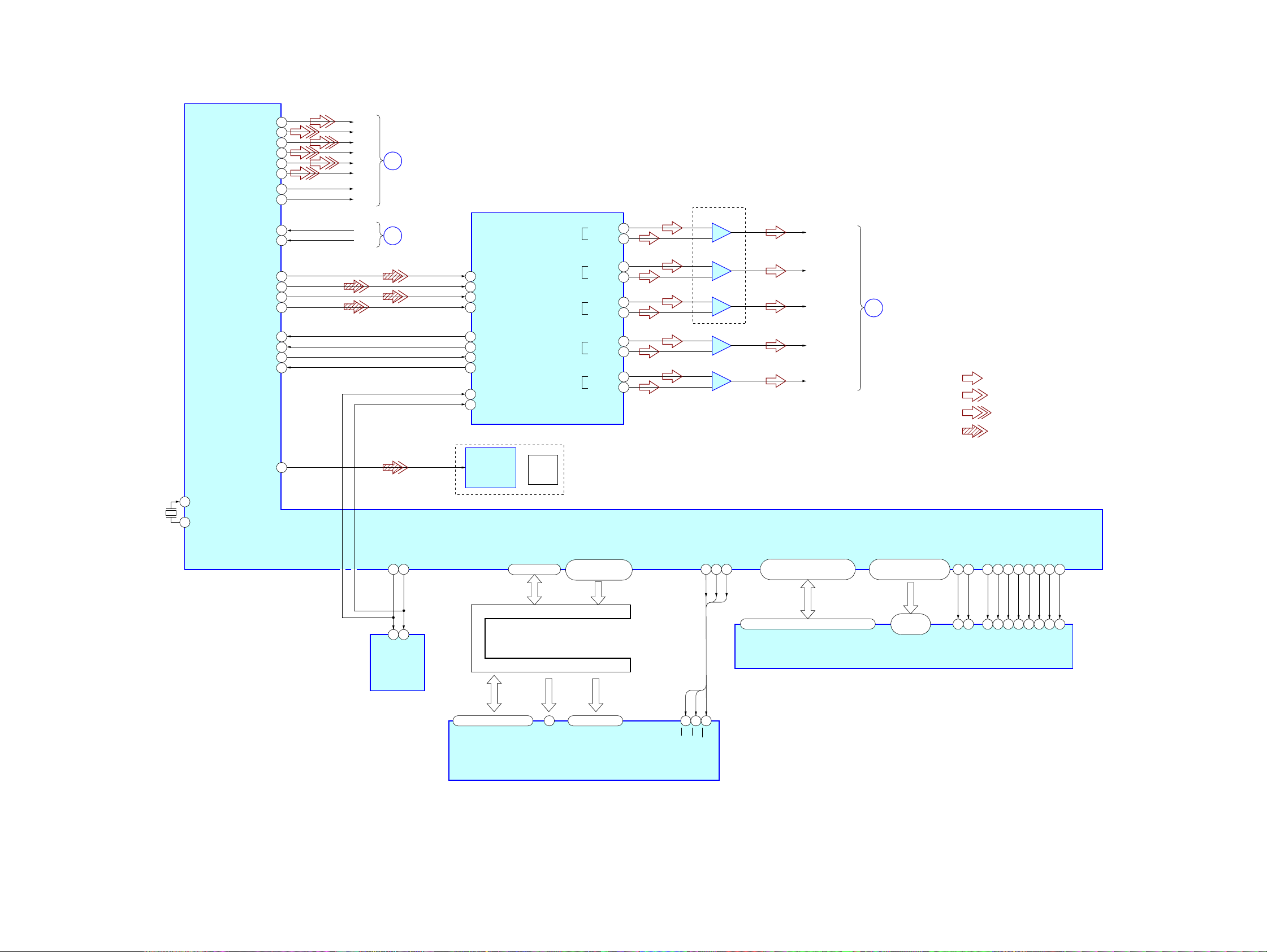
HCD-GNZ77D/GNZ88D
6-4. BLOCK DIAGRAM — AUDIO SECTION —
MAIN
SECTION
(Page 29)
E
DBFB FEED BACK
FRONT L
ADC RESET
SL OUT
SW OUT
CENTER
X1
12.288MHz
• Signal path
: AUDIO
: DIGITAL
R-CH
R-CH
SERIAL CLOCK
BUFFER
IC3
A/D CONVERTER
L IN
1
2
R IN
15
SCKI
7
PDWN
A/D CONVERTER
1
L IN
2
R IN
15
SCKI
7
PDWN
A/D CONVERTER
1
L IN
2
R IN
SCKI
15
7
PDWN
IC11
IC12
IC13
M751
(LOADING)
M741
(TABLE)
D OUT
LRCK
BCK
D OUT
LRCK
BCK
D OUT
LRCK
BCK
RE701
DISC TRAY
ADDRESS
DETECT
12
10
11
12
10
11
GNZ88D
12
10
11
S751
OPEN/CLOSE
DETECT
IC731
TABLE
ADDRESS
SENSOR
M
M
IC803
CLOSE OPEN
IC701
LOADING
4
MOTOR
2
DRIVE
IC712
TABLE
4
MOTOR
2
DRIVE
Q731
D/A CONVERTER
IC500
11
OUTL1
9
OUTL2
6
4
48
14
45
43
41
39
18
19
21
22
23
27
37
38
18
19
21
22
23
27
38
48
11
9
41
39
SM SD
R–CH
R–CH
SERIAL CLOCK
BUFFER
IC800
R–CH
R–CH
GNZ77D
3
79
76
77
78
65
72
86
85
X800
49MHz
SUB WOOFER AMP
HP AMP
IC880
GNZ88D
IC812
OUTR1
31
DATA
29
LRCK
30
BCK
36
XFSIIN
31
DATA
29
LRCK
30
BCK
36
XFSIIN
41
OPEN SWITCH
43
E–3
44
E–2
45
E–1
42
TABLE SENSE
48
7
LM–F
9
49
LM–R
7
46
TM–F
9
47
TM–R
OUTR2
XFSOIN
XFSOOUT
HPOUTL1
HPOUTL2
HPOUTR1
HPOUTR2
NSPMUTE
SOFTMUTE
SCSHIFT
SCLATCH
FSOCKO
D/A CONVERTER
IC700
NSPMUTE
SOFTMUTE
SCSHIFT
SCLATCH
XFSOIN
OUTL1
OUTL2
HPOUTR1
HPOUTR2
SYSTEM CONTROL
IC401(2/4)
SM LATCH3
SM LATCH2
SM LATCH1
SCDT
INIT
FSOI
SCDT
INIT
FSOI
SM CLK
SM DATA
SM RESET
HP MUTE
HP DET
AMP (FRONT LCH)
PWM A
6
PWM B
14
D/A CONVERTER
31
DATA
29
LRCK
30
BCK
36
XFSIIN
14
XFSOOUT
18
NSPMUTE
19
SOFTMUTE
21
SCDT
22
SCSHIFT
23
SCLATCH
27
INIT
37
FSOCKO
38
FSOI
48
XFSOIN
IC530
IC600
INIT
NSP MUTE
SOFT MUTE
OUT A
OUT B
/RESET
OUTL1
OUTL2
OUTR1
OUTR2
SW OUT
/SD
28
l
30
25
l
27
4
5
11
9
6
4
F
D
R-CH
R-CH
MAIN
SECTION
(Page 29)
MAIN
SECTION
(Page 29)
DC DETECT
Q850,851
AMP (SURROUND)
4
PWM A
6
PWM B
6
PWM A
14
PWM B
DC DETECT
Q840
R-CH
R-CH
IC630
OUT A
OUT B
OUT C
OUT D
RESET AB
RESET CD
AMP (CENTER)
IC730
OUT A
OUT B
/RESET
TM1500 (1/3)
MUTE
Q1400,1401
MUTE CONTROL
Q486
33
30
25
22
3
/SD
5
15
28
l
30
25
l
27
4
/SD
5
R-CH
R-CH
L
R
D486
FRONT
SPEAKER
DC DETECT
Q860,861
DC DETECT
Q870,871
R-CH
UNREG+8V
FAN DET
R-CH
R-CH
G
TM1500 (2/3)
TM1500 (3/3)
MAIN
SECTION
(Page 29)
J1401
PHONES
GNZ88D
L
SURROUND
SPEAKER
R
CENTER
SPEAKER
HCD-GNZ77D/GNZ88D
3030
 Loading...