

Sony HCD-GNZ777D, HCD-GNZ888D Service Manual

HCD-GNZ777D/GNZ888D
SERVICE MANUAL
Ver. 1.2 2007. 10
• HCD-GNZ777D/GNZ888D are the
tuner, deck, DVD and amplifier
section in MHC-GNZ777D/GNZ888D.
(Photo: HCD-GNZ777D)
DVD
Section
Tape Deck
Section
E Model
Model Name Using Similar Mechanism HCD-GNZ77D/GNZ88D
DVD Mechanism Type CDM74HF-DVBU101//C
Optical Pick-up Name KHM-313CAB/C2NP
Model Name Using Similar Machanism HCD-GNZ77D/GNZ88D
Amplifier section
HCD-GNZ888D
The following are measured at AC 120, 127, 220, 240 V,
50/60 Hz
Power output (rated)
Front speaker: 130 W + 130 W
(4 Ω, 1 kHz, 1% THD)
RMS output power (reference)
Front speaker: 160 W + 160 W
(per channel at 4 Ω, 1 kHz, 10%
THD)
Center speaker: 50 W (per channel at 4 Ω, 1 kHz,
10% THD)
Surround speaker: 50 W + 50 W
(per channel at 8 Ω, 1 kHz, 10%
THD)
HCD-GNZ777D
The following are measured at AC 120, 127, 220, 240 V,
50/60 Hz
Power output (rated) 130 W + 130 W
(4 Ω, 1 kHz, 1% THD)
RMS output power (reference)
Front speaker: 160 W + 160 W
(per channel at 4 Ω, 1 kHz, 10%
THD)
SPECIFICATIONS
Inputs
VIDEO INPUT: VIDEO: 1 Vp-p, 75 ohms
AUDIO L/R: Voltage 250 mV,
impedance 47 kilohms
TV/SAT AUDIO IN L/R:
Voltage 250 mV/450 mV,
impedance 47 kilohms
MIC 1 or 2: Sensitivity 1 mV,
impedance 10 kilohms
Outputs
SUBWOOFER OUT: Voltage 250 mV,
impedance 1 kilohm
VIDEO OUT: max. output level
1 Vp-p, unbalanced, Sync
negative load impedance
75 ohms
COMPONENT VIDEO OUT:
Y: 1 Vp-p, 75 ohms
PB/CB: 0.7 Vp-p, 75 ohms
PR/CR: 0.7 Vp-p, 75 ohms
S-VIDEO OUT: Y: 1 Vp-p, unbalanced,
Sync. negative
C: 0.286 Vp-p, load
impedance 75 ohms
PHONES: accepts headphones of
8 ohms or more
DVD DIGITAL OUT (MHC-GNZ777D only):
Wavelength: 660nm
– Continued on next page –
9-887-690-03
2007J04-1
© 2007. 10
DVD DECK RECEIVER
Sony Corporation
Personal Audio Division
Published by Sony Techno Create Corporation
1

HCD-GNZ777D/GNZ888D
Disc player section
System Compact disc and digital
audio and video system
Laser Semiconductor laser
(DVD: λ=650 nm,
CD: λ=790 nm)
Emission duration:
continuous
Frequency response DVD (PCM 48 kHz):
2 Hz – 22 kHz (±1 dB)
CD: 2 Hz – 20 kHz (±0.5 dB)
Video color system format
Russian models: PAL
Other models: NTSC and PAL
Tape deck section
Recording system 4-track 2-channel stereo
Frequency response 50 – 13,000 Hz (±3 dB),
using Sony TYPE I tape
Tuner section
FM stereo, FM/AM superheterodyne tuner
FM tuner section
Tuning range 87.5 – 108.0 MHz
(50-kHz step)
Antenna FM lead antenna
Antenna terminals 75 ohm unbalanced
Intermediate frequency 10.7 MHz
AM tuner section
Tuning range
Saudi Arabian and Russian models:
531 – 1,602 kHz (with the
interval set at 9 kHz)
Other models: 531 – 1,602 kHz (with the
interval set at 9 kHz)
530 – 1,610 kHz (with the
interval set at 10 kHz)
Antenna AM loop antenna
Antenna terminals External antenna terminal
Intermediate frequency 450 kHz
General
Power requirements
Saudi Arabian model: 120 – 127 V, 220 – 240 V AC,
50/60 Hz
Adjustable with voltage
selector
Thai model: 220 V AC, 50/60 Hz
Russian and Indian models:
220 – 240 V AC, 50/60 Hz
Other models: 120 V, 220 – 240 V AC,
50/60 Hz
Adjustable with voltage
selector
Power consumption
MHC-GNZ888D 120 W
MHC-GNZ777D 90 W
Dimensions (w/h/d) (Approx.)
280 × 323.5 × 373.5 mm
Mass (Approx.)
HCD-GNZ888D 7.1 kg
HCD-GNZ777D 6.9 kg
Design and specifications are subject to change without
notice.
SAFETY-RELATED COMPONENT WARNING!!
COMPONENTS IDENTIFIED BY MARK 0 OR DOTTED LINE
WITH MARK 0 ON THE SCHEMATIC DIAGRAMS AND IN
THE PARTS LIST ARE CRITICAL TO SAFE OPERATION.
REPLACE THESE COMPONENTS WITH SONY P ARTS WHOSE
PART NUMBERS APPEAR AS SHOWN IN THIS MANUAL OR
IN SUPPLEMENTS PUBLISHED BY SONY.
2

HCD-GNZ777D/GNZ888D
Ver. 1.2
Notes on Chip Component Replacement
•Never reuse a disconnected chip component.
• Notice that the minus side of a tantalum capacitor may be
damaged by heat.
Flexible Circuit Board Repairing
•Keep the temperature of soldering iron around 270°C during
repairing.
• Do not touch the soldering iron on the same conductor of the
circuit board (within 3 times).
• Be careful not to apply force on the conductor when soldering
or unsoldering.
UNLEADED SOLDER
Boards requiring use of unleaded solder are printed with the lead
free mark (LF) indicating the solder contains no lead.
(Caution: Some printed circuit boards may not come printed with
the lead free mark due to their particular size)
: LEAD FREE MARK
Unleaded solder has the following characteristics.
• Unleaded solder melts at a temperature about 40 °C higher than
ordinary solder.
Ordinary soldering irons can be used but the iron tip has to be
applied to the solder joint for a slightly longer time.
Soldering irons using a temperature regulator should be set to about
350 °C.
Caution: The printed pattern (copper foil) may peel away if the
heated tip is applied for too long, so be careful!
• Strong viscosity
Unleaded solder is more viscou-s (sticky , less prone to flo w) than
ordinary solder so use caution not to let solder bridges occur such
as on IC pins, etc.
• Usable with ordinary solder
It is best to use only unleaded solder but unleaded solder may also
be added to ordinary solder.
NOTES ON LASER DIODE EMISSION CHECK
The laser beam on this model is concentrated so as to be focused on
the disc reflective surface by the objective lens in the optical pickup block. Therefore, when checking the laser diode emission,
observe from more than 30 cm away from the objective lens.
Laser component in this product is capable
of emitting radiation exceeding the limit for
Class 1.
This appliance is
claassified as a CLASS 1
LASER product. This
label is located on the
rear exterior.
CAUTION
Use of controls or adjustments or performance of procedures
other than those specified herein may result in hazardous
radiation exposure.
NOTES ON HANDLING THE OPTICAL PICK-UP BLOCK
OR BASE UNIT
The laser diode in the optical pick-up block may suffer electrostatic
breakdown because of the potential difference generated by the
charged electrostatic load, etc. on clothing and the human body.
During repair, pay attention to electrostatic break-down and also
use the procedure in the printed matter which is included in the
repair parts.
The flexible board is easily damaged and should be handled with
care.
3
HCD-GNZ777D/GNZ888D
Ver. 1.1
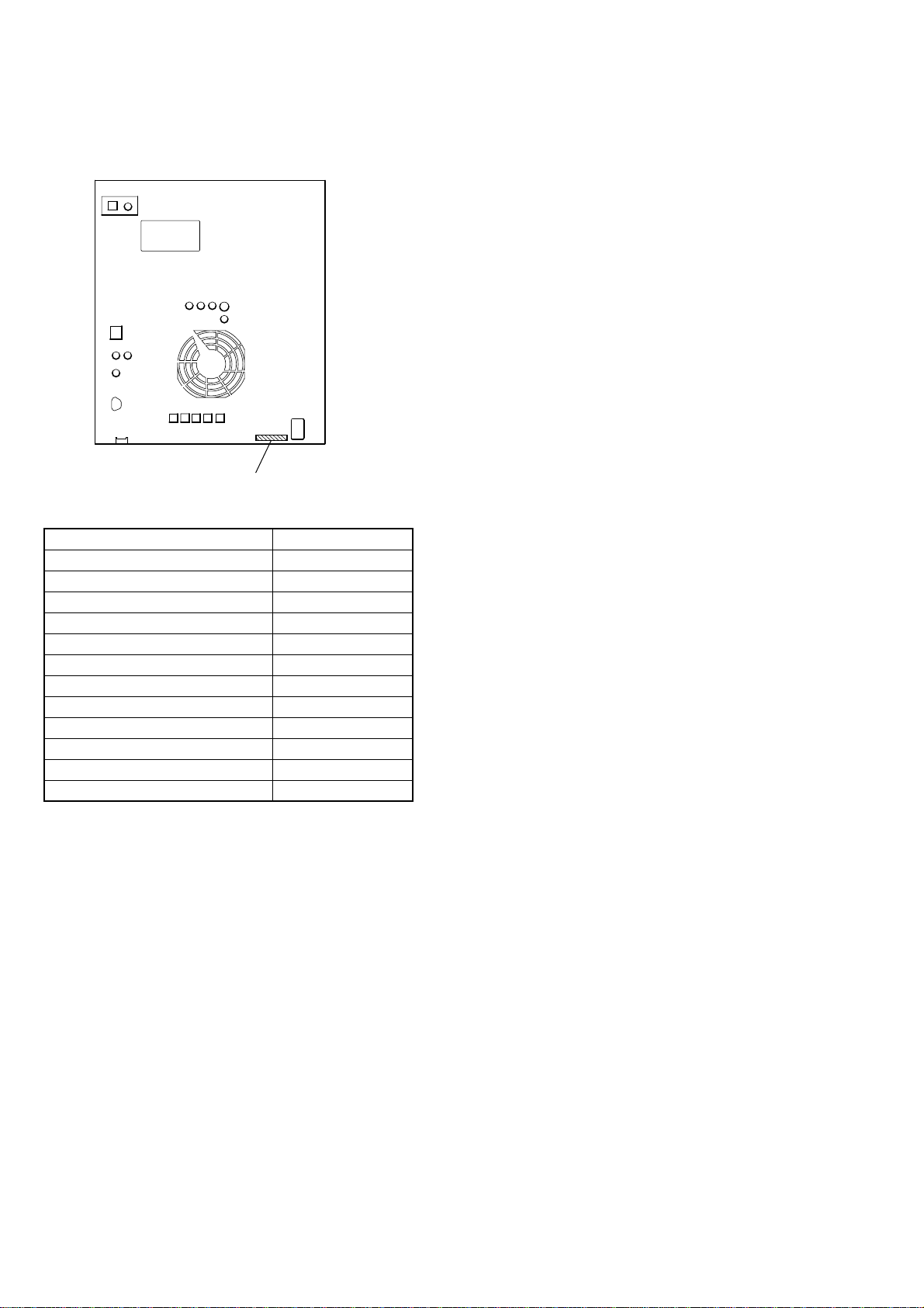
MODEL IDENTIFICATION
– BACK PANEL –
PARTS No.
MODEL PARTS No.
GNZ888D: E3, E15 2-897-540-0s
GNZ888D: EA 2-897-540-1s
GNZ888D: SP 2-897-540-2s
GNZ888D: E12 2-897-540-3s
GNZ888D: TH 2-897-540-4s
GNZ888D: PH 2-897-540-5s
GNZ777D: E3, E15 2-897-541-0s
GNZ777D: EA 2-897-541-1s
GNZ777D: SP 2-897-541-2s
GNZ777D: E12, E13 2-897-541-3s
GNZ777D: TH 2-897-541-4s
GNZ777D: PH 2-897-541-5s
• Abbreviation
E3 : 240 V AC area in E model
E12 : 220-240 V AC area in E model
E13 : Russian model
E15 : Iran model
EA : Saudi arabia model
PH : Philippine model
SP : Singapore model
TH : Thai model
4

TABLE OF CONTENTS
HCD-GNZ777D/GNZ888D
1. GENERAL
Guide to parts and controls...................................................... 6
2. DISASSEMBLY
2-1. Case ................................................................................... 14
2-2. Loading Panel.................................................................... 14
2-3. Front Panel Section ........................................................... 15
2-4. DVD Block Section........................................................... 15
2-5. Back Panel Section............................................................ 16
2-6. Main Board, ADC Board .................................................. 16
2-7. Speaker Board, Smaster Board ......................................... 17
2-8. Power Board...................................................................... 17
2-9. Tape Mechanism Deck ...................................................... 18
2-10. Lid TC-R Assy, Lid TC-L Assy ........................................ 18
2-11. Mic Board, Headphone Board........................................... 19
2-12. Video Board....................................................................... 19
2-13. DMB16 Board ...................................................................20
2-14. Sensor Board ..................................................................... 20
2-15. Motor (TB) Board ............................................................. 21
2-16. Motor (LD) Board ............................................................. 21
2-17. Pick-Up Unit ..................................................................... 22
2-18. SW Board, Driver Board...................................................22
3. TEST MODE ..................................................................... 23
4. MECHANICAL ADJUSTMENTS............................... 28
5. ELECTRICAL ADJUSTMENTS................................. 29
6. DIAGRAMS
6-1. Circuit Boards Location .................................................... 32
6-2. Block Diagram — RF/Servo Section — ...........................33
6-3. Block Diagram — Video Section —.................................34
6-4. Block Diagram — Main Section —..................................35
6-5. Block Diagram — Audio Section — ................................ 36
6-6. Block Diagram — Function/Power Section —................. 37
6-7. Printed Wiring Boards — Driver Section —..................... 39
6-8. Schematic Diagram — Driver Section —......................... 40
6-9. Printed Wiring Board — Main Section — ........................ 41
6-10. Schematic Diagram — Main Section (1/4) — ..................42
6-11. Schematic Diagram — Main Section (2/4) — ..................43
6-12. Schematic Diagram — Main Section (3/4) — ..................44
6-13. Schematic Diagram — Main Section (4/4) — ..................45
6-14. Printed Wiring Board — DMB16 Section (1/2) — .......... 46
6-15. Printed Wiring Board — DMB16 Section (2/2) — .......... 47
6-16. Schematic Diagram — DMB16 Section (1/6) — ............. 48
6-17. Schematic Diagram — DMB16 Section (2/6) — ............. 49
6-18. Schematic Diagram — DMB16 Section (3/6) — ............. 50
6-19. Schematic Diagram — DMB16 Section (4/6) — ............. 51
6-20. Schematic Diagram — DMB16 Section (5/6) — ............. 52
6-21. Schematic Diagram — DMB16 Section (6/6) — ............. 53
6-22. Printed Wiring Board — Smaster Section (1/2) —........... 54
6-23. Printed Wiring Board — Smaster Section (2/2) —........... 55
6-24. Schematic Diagram — Smaster Section (1/4) — ............. 56
6-25. Schematic Diagram — Smaster Section (2/4) — ............. 57
6-26. Schematic Diagram — Smaster Section (3/4) — ............. 58
6-27. Schematic Diagram — Smaster Section (4/4) — ............. 59
6-28. Printed Wiring Board — Video Section — ....................... 60
6-29. Schematic Diagram — Video Section —.......................... 61
6-30. Printed Wiring Board — ADC Section — ........................ 62
6-31. Schematic Diagram — ADC Section —........................... 63
6-32. Printed Wiring Board — Display Section — .................... 64
6-33. Schematic Diagram — Display Section —....................... 65
6-34. Printed Wiring Boards — Key Section — ........................ 66
6-35. Schematic Diagram — Key Section —............................. 67
6-36. Printed Wiring Boards — Mic/Headphone Section —.....68
6-37. Schematic Diagram — Mic/Headphone Section — ......... 69
6-38. Printed Wiring Board — Speaker Section — ................... 70
6-39. Schematic Diagram — Speaker Section — ...................... 71
6-40. Printed Wiring Board — Power Section — ...................... 72
6-41. Schematic Diagram — Power Section — .........................73
7. EXPLODED VIEWS
7-1. Main Section ..................................................................... 88
7-2. Front Panel Section (1)...................................................... 89
7-3. Front Panel Section (2)...................................................... 90
7-4. Front Panel Section (3)...................................................... 91
7-5. Chassis Section ................................................................. 92
7-6. DVD Block Section........................................................... 93
7-7. DVD Mechanism Deck Section (1) .................................. 94
7-8. DVD Mechanism Deck Section (2) .................................. 95
8. ELECTRICAL PARTS LIST ........................................ 96
5
HCD-GNZ777D/GNZ888D
SECTION 1
GENERAL
This section is extracted
from instruction manual.
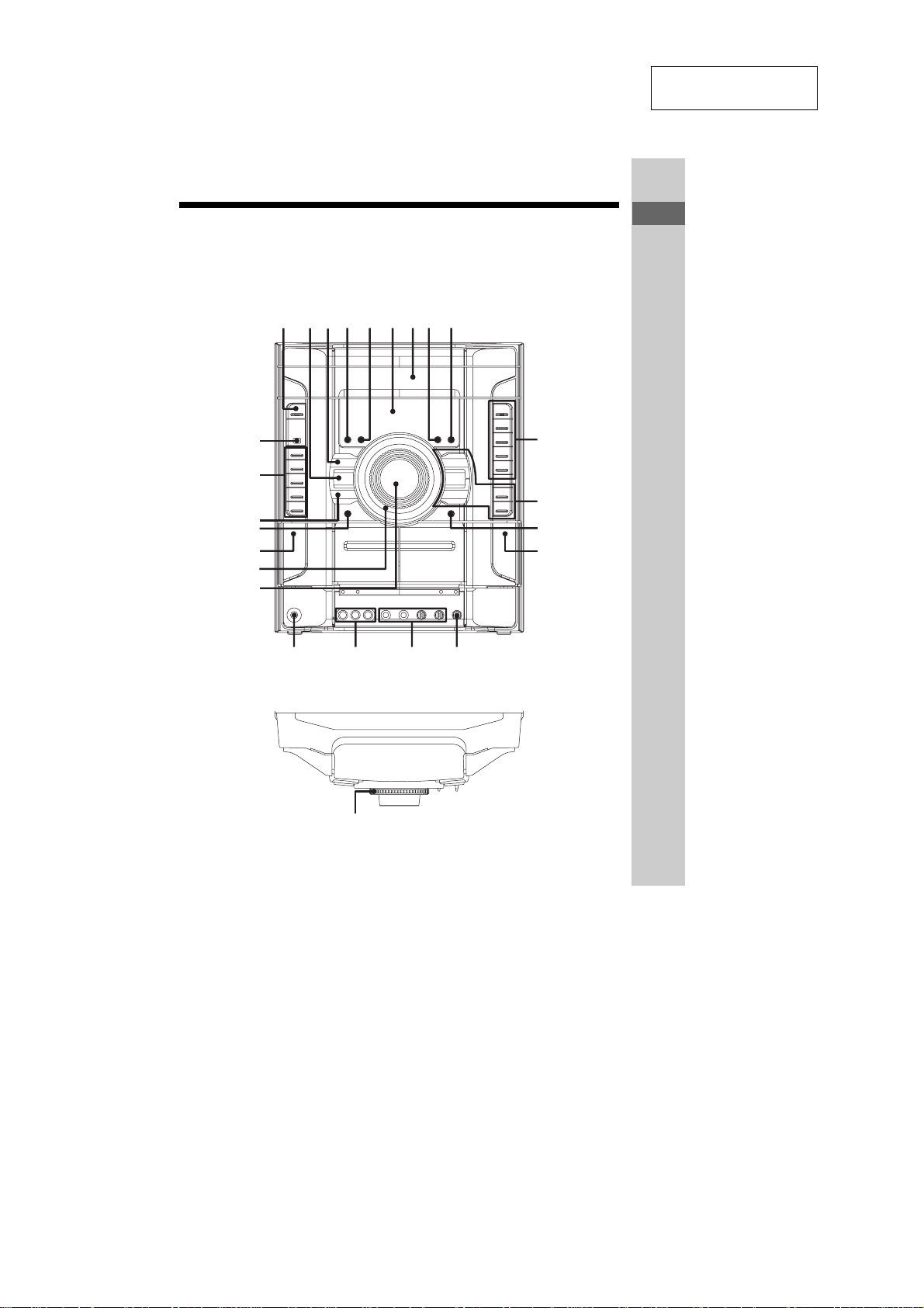
Guide to parts and controls
This manual mainly explains operations using the remote, but the same operations can
also be performed using the buttons on the unit having the same or similar names.
Front panel
12345
wf
wd
ws
wa
w;
ql
qk
6789
qgqhqj
qf
q;
qa
qs
qd
Guide to parts and controls
Top panel
wg
Continued
l
GB
9
6

HCD-GNZ777D/GNZ888D
1 "/1 STANDBY (pages 17, 18,
19, 22, 23, 54, 73, 74, 80, 81)
Press to turn the unit on or off.
B GROOVE (page 58)
Press to reinforce the bass.
3 EQ BAND/MEMORY (page 58)
Press to select a frequency band
when adjusting the equalizer.
4 DISPLAY (pages 20, 67)
Press to display disc information in
the front panel display or to change
the front panel display during Power
Saving Mode.
5 ILLUMINATION (page 67)
Press to change the power
illuminator.
F Display (pages 12, 67, 82)
G Disc tray (pages 12, 26, 76)
H CD SYNC (page 56)
Press to select CD Synchro
Recording.
I REC PAUSE/START (page 56)
Press to start recording.
J DISC 1 ~ 3 (page 27)
Press to select a disc.
DISC SKIP/EX-CHANGE
(pages 18, 26, 27)
Press to exchange other discs during
playback.
Z OPEN/CLOSE (pages 18, 26,
76)
Press to load or eject a disc.
K TUNING +/– (pages 53, 54)
Press to tune in a radio station.
M/m (fast forward/
rewind) (page 27)
Press to fast forward or rewind.
nN (play) (pages 26, 55, 56,
74)
X (pause) (pages 26, 55)
x (stop) (pages 26, 53, 55, 56,
80)
Press to start, pause or stop playback.
L DIRECTION (pages 55, 56, 66)
Press to select the tape playback
option.
M Z PUSH (Eject B) (page 55)
Press to insert or eject tape B.
Deck B (pages 55, 56, 66)
N ECHO LEVEL (page 61, 62)
Turn to adjust the microphone echo
effect.
O MIC 1/2 (jack) (pages 57, 62, 74)
Connect the microphones.
MIC 1/2 LEVEL (pages 57, 61,
74)
Turn to adjust the microphone
volume.
P VIDEO INPUT (jacks) (page 71)
Connect an audio or video
component.
Q PHONES (jack) (page 74)
Connect the headphones.
R MASTER VOLUME (pages 26,
65, 67, 74)
Turn to adjust the volume.
S Power illuminator (pages 67)
10
GB
7

HCD-GNZ777D/GNZ888D
T Z PUSH (Eject A) (page 55)
Press to insert or eject tape A.
Deck A (page 55)
U SOUND FIELD (page 59)
Press to select a sound field.
V PRESET EQ (page 58)
Press to select a preset effect.
W VIDEO (pages 67, 73)
TV/SAT (pages 67, 73, 75)
TAPE A/B (pages 55, 66, 67)
TUNER/BAND (pages 53, 67)
DVD (pages 18, 26, 56, 61, 67,
78)
Press to select a function.
wf Remote sensor (page 75)
wg . OPERATION DIAL >
(pages 27, 53, 56, 58, 59)
Turn to select a setting.
Guide to parts and controls
Continued
l
11
GB
8

DISPLAY
234 5 6 7 8 9 q;
1
NTSC
DCS
HCD-GNZ777D/GNZ888D
1
A Lights up when the color system of
the video output is NTSC (page 19).
B Lights up when DTS source is played
back (page 49).
C Lights up when Dolby Digital source
is played back (page 49).
D Lights up when disc number is
displayed.
E Lights up when the elapsed playing
time and the remaining playing time
for the title or chapter is displayed
(page 67).
F Displays the current status and
information (page 67).
G Lights up when the track information
is displayed.
H Lights up when VIDEO CD with PBC
functions is played back (page 29).
I Indicators for the TUNER function
(page 53).
J Lights up when Karaoke Mode is
turned on (page 61).
K Lights up during recording (page 56).
L Indicators for sound field (page 59).
(MHC-GNZ888D only)
“SUR” lights up when “LINK SUR”
or “2CH SUR” is selected.
(MHC-GNZ777D only)
“SUR” lights up when “HP SUR” or
“2CH SUR” is selected.
B
A
B
qaqsqdqfqgqhqjqlw;wa qkws
M Indicators for the TAPE function
(page 55).
“A” and “B” lights up when the
system is turned on.
“b” or “B” lights up when there is a
tape in the deck and indicates the tape
playback direction. “RELAY”, “g”
and “j” indicates the tape
playback option.
N Indicates the selected play mode
(page 31).
“SHUF” lights up when Shuffle Play
is activated. “PGM” lights up when
Program Play is activated. “REP”
lights up when Repeat Play is set to
“ALL DISCS”, “ONE DISC”,
“ALBUM” or “ON”. “REP 1” lights
up when Repeat Play is set to
“TITLE”, “CHAPTER”, “TRACK”
or “FILE”.
O Indicators for the disc tray (page 26).
“” lights up when there is a disc on
the disc tray. “ ”, “1”, “2” and “3”
light up when the system is turned on.
P “GROOVE” lights up when
“GROOVE ON” is selected.
“V GROOVE” lights up when
“V-GROOVE ON” is selected
(page 58).
Q Indicates the disc playback condition.
“N” lights up when source is played
back. “X” lights up when the source
is paused.
12
GB
9

HCD-GNZ777D/GNZ888D
qk Lights up when the Sleep Timer is
activated (page 65).
ql Lights up when the Play Timer or
Timer Recording is set (page 65).
w; Indicators for the DVD function
(page 26).
“DVD” lights up when DVD VIDEO,
DVD-R/-RW in VR mode or DATA
DVD is detected. “MP3” lights up
when MP3 audio tracks are played
back. “VCD” lights up when VIDEO
CD or Super VCD is detected. “CD”
lights up when AUDIO CD or DATA
CD is detected.
wa Lights up when “P AUTO” or
“P VIDEO” is selected (page 20).
ws Indicators for sound field (page 59).
(MHC-GNZ888D only)
“VIRTUAL” and “DCS” light up
when “V.M.DIM.” is selected. “;
PL” or “; PL II” lights up when Pro
Logic decoding or Pro Logic II
Movie/Music decoding is performed.
(MHC-GNZ777D only)
“VIRTUAL” lights up when
“VIRTUAL A”, “VIRTUAL B” or
“HP VIRTUAL” is selected.
Remote
wh
wg
wf
wd
ws
wa
w;
ql
qk
qj
qh
1 THEATRE SYNC (page 25)
Press to operate the THEATRE
SYNC function.
2 TV ?/1 (on/standby) (page 21)
Press to turn the TV on or off.
1
2
3
4
5
6
7
8
9
q;
qa
qs
qd
qf
qg
Guide to parts and controls
?/1 (on/standby) (pages 17, 22,
74)
Press to turn the unit on or off.
3 DISC SKIP (page 27)
Press to skip a disc.
4 FUNCTION +/– (pages 26, 53,
55, 73)
Press to select a function.
5 PICTURE NAVI (pages 36, 38)
Press to search for a scene or a file.
Continued
l
13
GB
10

HCD-GNZ777D/GNZ888D
F REPEAT/FM MODE (pages 33,
54, 79)
Press to change the Repeat Play
setting.
Press to select the FM monaural or
stereo reception.
G AUDIO (pages 28, 62, 69)
Press to select the audio format.
H SUBTITLE/D.TUNING
(pages 28, 54)
Press to turn off or change the
language of the subtitle.
Press to enter direct tuning mode.
I ANGLE (page 28)
Press to change the angle.
J (pages 24, 27)
Press to select an album.
K DVD/TUNER MENU (pages 34,
38, 53)
Press to display the menu of the
DVD player.
Press to preset a radio station.
L SOUND FIELD (page 59)
Press to select a sound field.
M TV VOL +/–* (page 21)
Press to adjust the TV volume.
VOLUME +/–* (pages 26, 65, 74)
Press to adjust the volume.
N DISPLAY (pages 31, 46, 63,
87)
Press to turn on or off or change the
Control Menu display on the TV
screen.
O TV CH +/– (page 21)
Press to select a TV channel.
PRESET +/– (page 53)
Press to select a preset station.
./> (go backward/go
forward) (pages 27, 37, 56)
Press to go backward or go forward.
c STEP C (page 27)
Press to watch one frame at a time.
REPLAY /ADVANCE
(page 27)
Press to replay the previous scene or
fast forward the current scene.
TUNING +/– (pages 53, 54)
Press to tune in a radio station.
SLOW /SLOW (page 27)
Press to watch frame by frame.
m/M (rewind/fast forward
(page 27)
Press to rewind or fast forward.
H* (play) (pages 26, 55, 74)
X (pause) (pages 26, 55)
x (stop) (pages 26, 53, 55)
Press to start, pause or stop playback.
P TV (page 21)
Hold down TV and press the button
you want to operate the TV.
Q O RETURN (pages 30, 36, 38)
Press to return to the previous
display.
14
GB
11

HCD-GNZ777D/GNZ888D
R V/v/B/b (pages 22, 31, 53, 63,
65)
Press to select the settings.
ENTER (pages 22, 31, 53, 58,
65)
Press to enter the selection.
S DVD TOP MENU (page 34)
Press to display the DVD title.
T -/-- (page 21)
Press to enter a double digit channel
number for TV.
CLEAR (pages 23, 24, 31, 38)
Press to cancel the play mode or clear
a mistake when you press the
incorrect numeric button.
U Numeric buttons* (pages 21, 27,
43, 53)
Press to tune or preset a radio station,
enter a track or file number, etc.
V KEY CONTROL 2/# (page 64)
SCORE (page 64)
KARAOKE MODE (page 62)
KARAOKE PON (page 64)
Press to enjoy the karaoke function.
W DISPLAY (pages 67)
Press to display disc information in
the front panel display or to change
the front panel display during Power
Saving Mode.
wf TIME/TEXT (pages 67, 69)
Press to check the elapsed playing
time, remaining time, etc.
wg TV INPUT (page 21)
Press to switch the TV’s input
source.
SLEEP (pages 24, 65)
Press to activate the sleep timer.
wh TIMER MENU (pages 22, 65)
Press to set the time and timer.
*The numeric button 5, TV VOL +, VOLUME
+ and H buttons have a tactile dot. Use the
tactile dot as a reference when operating the
system.
Guide to parts and controls
12
15
GB

Note : Disassemble the unit in the order as shown below.
SET
2-1. CASE
(Page 14)
HCD-GNZ777D/GNZ888D
SECTION 2
DISASSEMBLY
2-2. LOADING PANEL
(Page 14)
2-3. FRONT PANEL SECTION
(Page 15)
2-4. DVD BLOCK SECTION
(Page 15)
2-5. BACK PANEL SECTION
(Page 16)
2-6. MAIN BOARD, ADC BOARD
(Page 16)
2-7. SPEAKER BOARD,
SMASTER BOARD
(Page 17)
2-9. TAPE MECHANISM DECK
(Page 18)
2-10. LID TC-R ASSY ,
LID TC-L ASSY
(Page 18)
2-11. MIC BOARD,
HEADPHONE BOARD
(Page 19)
2-12. VIDEO BOARD
(Page 19)
2-13. DMB16 BOARD
(Page 20)
2-17. PICK-UP UNIT
(Page 22)
2-18. SW BOARD,
DRIVER BOARD
(Page 22)
2-8. POWER BOARD
(Page 17)
2-14. SENSOR BOARD
(Page 20)
2-15. MOTOR (TB) BOARD
(Page 21)
2-16. MOTOR (LD) BOARD
(Page 21)
13
HCD-GNZ777D/GNZ888D
)
Note : Follow the disassembly procedure in the numerical order given.
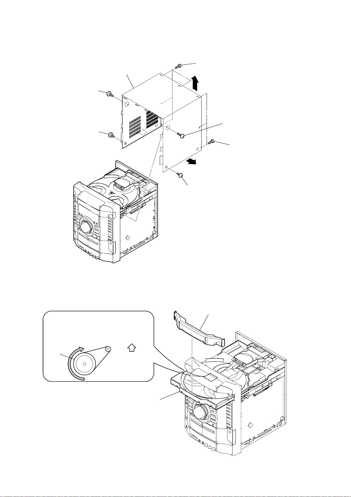
2-1. CASE
9
case
4
screw
(case 3 TP2)
3
screw
(case 3 TP2)
7
5
four screws (+BVTP 3
8
2
(case 3 TP2)
7
×
screw
6
three screws
(+BVTT 3
8)
×
6
2-2. LOADING PANEL
CD mechanism deck (CDM74)
1
Turn the pulley to the direction of the arrow.
pulley
Front panel side
1
screw
(case 3 TP2)
3
loading panel
14
2
Pull-out the disc tray.

2-3. FRONT PANEL SECTION
)
2
screw
(tapping screw)
front panel section
qd
1
(+BVTP 3
4
(+BVTP 3
screw
three
qs
CN1967 (2P)
×
5
screws
×
0
8)
8)
CN205 (9P)
8
qa
CN503 (3P)
9
CN121 (3P)
CN131 (8P)
HCD-GNZ777D/GNZ888D
6
wire (flat type) (25 core)
(CN201)
3
screw
(tapping screw)
7
wire (flat type) (11 core)
(CN101)
2-4. DVD BLOCK SECTION
8
DVD block section
7
CN1880 (8P)
4
2
wire (flat type) (19 core)
(CN521)
3
wire (flat type) (13 core)
(CN301)
5
three
(+BVTP 3
1
wire (flat type) (13 core)
(CN701)
screws
×
8)
6
four
screws
(+BVTP 3
×
8
15

HCD-GNZ777D/GNZ888D
)
d
2-5. BACK PANEL SECTION
9
back panel section
1
connector (9 core)
2
two
screws
(+BVTP 3
7
×
8)
3
two
screws
(+BVTP 3
4
(+BVTP 3
6
(+BVTP 3
four
5
(+BVTP 3
three
screws
×
8)
screws
two
×
×
8)
screws
8)
×
8
2-6. MAIN BOARD, ADC BOARD
3
CN812 (2P)
CN501 (12P)
2
8
CN580 (3P)
4
two
screws
(+BVTP 3
×
8
ADC board
8)
1
wire (flat type) (15 core)
(CN105) (GNZ777D)
wire (flat type) (17 core)
(CN105) (GNZ888D)
9
MAIN boar
16
7
CN590 (7P)
6
5
two
screws
(+BVTP 3
×
8)

2-7. SPEAKER BOARD, SMASTER BOARD
d
)
9
three
screws
-CR)
)
6
CN502 (8P)
(+BV3 (3
qs
heat sink assy
8
two
screws
(+BV3 (3
qd
SMASTER board
HCD-GNZ777D/GNZ888D
-CR)
)
2-8. POWER BOARD
5
(+BV3 (3
qf
screw
(tapping)
7
(+BV3 (3
qa
screw
(+BVTP 3
three
screws
two
-CR)
screws
-CR)
×
)
0
)
8)
qg
screw (tapping)
qs
A
bracket(SMPS-B5)
3
CN1700 (2P)
2
CN1601 (4P)
qa
three
(+BVTP 3
screws
qd
screw
(tapping)
×
8)
4
(+BVTP 3
1
CN1500 (4P)
A
two
screws
5
SPEAKER boar
screw
1
(+BVTP 3
2
(+BV3 (3
×
8)
screw
×
8)
-CR)
ql
bracket assy
6
screw (+BV3 (3
0
four
qk
POWER board
-CR)
qj
bracket (boss)
screws (+BVTP 3
4
CNP1100 (2P)
×
qh
bracket
(boss)
)
7
8)
8
two
(+BVTP 3
screws
3
SMPS sheet
9
bracket (TRANS-5CH)
×
8)
17

HCD-GNZ777D/GNZ888D
)
r
2-9. TAPE MECHANISM DECK
4
tape mechanism deck
1
two
screws
(+BVTP 2.6 (3CR)
2-10. LID TC-R ASSY, LID TC-L ASSY
2
damper
5
lid TC-L assy
2
two
screws
(+BVTP 2.6 (3CR))
3
two
screws
(+BVTP 2.6 (3CR))
18
6
spring (TC-L)
3
4
spring (TC-R)
lid TC-R assy
1
dampe

2-11. MIC BOARD, HEADPHONE BOARD
)
1
knob (MIC)
3
4
HEADPHONE board
HCD-GNZ777D/GNZ888D
2
three
(+BVTP 2.6 (3CR))
screws
7
holder (MIC PWB DVD)
2-12. VIDEO BOARD
2
(+BVTP 3
5
two
screws
(+BVTP 3
6
VIDEO board
7
CN401 (5P)
screw
×
8)
×
6
MIC board
5
three
(+BVTP 2.6 (3CR))
8)
screws
1
screw
(+BVTP 3
4
wire (flat type) (13 core)
(CN1966)
×
8)
3
shield plate (video
19

HCD-GNZ777D/GNZ888D
)
2-13. DMB16 BOARD
4
two
screws
(+BVTP 3
6
screw
(+BVTP 3
7
bracket mediatek
8
two
screws
(+BVTP 3
1
CN201 (6P)
×
3
two
screws
×
8)
×
8)
8)
(+BVTP 3
5
DMB16 board
9
two
(+BVTP 3
2
wire (flat type) (24 core
(CN101)
screws
0
cover (CDM)
×
×
8)
8)
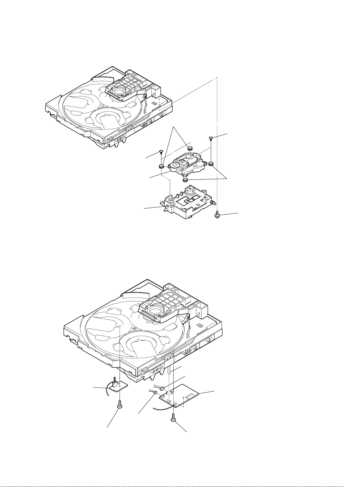
2-14. SENSOR BOARD
2
tray
1
floating
(+PTPWH M2.6)
6
floating
(+PTPWH M2.6)
7
gear (geneva)
screw
8
screw
(+BTTP (M2.6))
screw
9
SENSOR board
0
CN731
(3P)
3
belt (table)
4
floating
(+PTPWH M2.6)
5
screw
pulley (table)
20

2-15. MOTOR (TB) BOARD
table assy
2
stopper
1
HCD-GNZ777D/GNZ888D
2
stopper
6
table motor assy (M741)
2-16. MOTOR (LD) BOARD
4
Remove the two solderings of motor.
5
loading motor assy (M751)
4
MOTOR (TB) board
5
Remove the two solderings of motor.
3
two
screws
(+BTTP (M2.6))
2
two
screws
(+BTTP (M2.6))
3
MOTOR (LD) board
1
belt (loading)
21
HCD-GNZ777D/GNZ888D
)
d
2-17. PICK-UP UNIT
3
two insulator screws
6
pick-up unit
5
two insulators
2
two insulator screws
4
two insulators
2-18. SW BOARD, DRIVER BOARD
7
holder (310)
7
CN702 (5core)
4
CN703 (4P)
1
floating
(+PTPWH M2.6
screw
22
2
SW board
3
1
screw
(+BTTP (M2.6))
CN704 (2P)
6
5
two
screws
(+BTTP (M2.6))
DRIVER (F) boar

SECTION 3
TEST MODE
HCD-GNZ777D/GNZ888D
[PANEL TEST MODE]
•This mode is used to check the fluorescent indicator tube, LEDs,
keys, V OLUME jog and OPERATION DIAL jog, model, destination and software version.
Procedure:
1. Press x button, [ILLUMINATION] button and [DISC 2] button
simultaneously.
2. All LEDs and segments in fluorescent indicator tube are lighted
up. All LEDs are lighted up in red.
3. When you want to enter to the software version dispaly mode,
press [DISC 1] button. The model information appears on the
fluorescent indicator tube. “GRL2D” is shown for HCDGNZ777D and “GRL4D” is shown for HCD-GNZ888D. Press
[DISC 1] button again to view the destination information.
4. Each time [DISC 1] button is pressed, the display changes from
MC version, SYS version, UI version, DVD version, CDMA
version, CDMB version, ST version, TA version, TM version,
TC version in this order, and returns to the model information
display.
5. When [DISC 3] button is pressed while the version numbers are
being displayed except model and destination, the date of the
software creation appears. When [DISC 3] button is pressed
again, the display returns to the software version display . When
[DISC 1] button is pressed while the date of the software creation
is being displayed, the date of the software creation is displayed
in the same order of software version display.
6. Press [DISC 2] button, the key check mode is activated.
7. In the key check mode, the fluorescent indicator tube displays
“K 0 V0 J0”.
Each time a button is pressed, “K” value increases. However,
once a button has been pressed, it is no longer taken into account.
“V” value increases in the manner of 0, 1, 2, 3 ... if [MASTER
VOLUME] knob is turned clockwise, or it decreases in the manner
of 0, 9, 8, 7 ... if [MASTER VOLUME] knob is turned
counterclockwise.
“J” value increases in the manner of 0, 1, 2, 3... if [OPERATION
DIAL] knob is turned clockwise, or it decreases in the manner of
0, 9, 8, 7... if [OPERATION DIAL] knob is turned counterclockwise.
8. When [DISC SKIP/EX-CHANGE] button is pressed after all LEDs
and segments in fluorescent indicator tube light up, alternate
segments in fluorescent indicator tube would light up. If you
press [DISC SKIP/EX-CHANGE] button again, another half of
alternate segments in fluorescent indicator tube would light up.
When [DISC SKIP/EX-CHANGE] button is pressed again, all
segments lights off. Press [DISC SKIP/EX-CHANGE] button again
would cause all segments lights up.
9. To release from this mode, press three buttons in the same
manner as step 1, or disconnect the power cord.
[COMMON TEST MODE]
•This mode is used to check operations of the respectiv e sections
of Amplifier and Tape.
Procedure:
•To enter Common Test Mode
1. Press x button, [ILLUMINATION] button and [DISC 3] button
simultaneously.
2. The DVD ring flash synchronously on the fluorescent indicator
tube. The function is changed to TV.
• Check of Amplifier
1. Press [EQ BAND/MEMORY] button repeatedly until a message
“GEQ MAX” appears on the fluorescent indicator tube. GEQ
increases to its maximum.
2. Press [EQ BAND/MEMORY] button repeatedly until a message
“GEQ MIN” appears on the fluorescent indicator tube. GEQ
decreases to its minimum.
3. Press [EQ BAND/MEMORY] button repeatedly until a message
“GEQ FLAT” appears on the fluorescent indicator tube. GEQ
is set to flat.
4. When the [MASTER VOLUME] knob is turned clockwise even
slightly, the sound volume increases to its maximum and a
message “VOLUME MAX” appears on the fluorescent indicator
tube.
5. When the [MASTER VOLUME] knob is turned counterclockwise
even slightly, the sound v olume decreases to its minimum and a
message “VOLUME MIN” appears on the fluorescent indicator
tube.
•Tape function
1. When a tape is inserted in Deck B and recording is started, the
function is changed to TV. When [CD SYNC] button is pressed
during recording in function, ALC (Automatic Logic Control)
is turned on.
2. During recording, press m button will stop the recording and
the function is changed to TAPE B and rewind the tape in Deck
B until the recording start position and playback of the tape in
Deck B is started. If the [REC PAUSE/START] button is pressed
for a pause and pressed again to resume recording during
recording time, when the tape is rewind, the tape will be rewind
until the position where the pause is applied.
•To release from Common Test mode
1. To release from this mode, press ?/1 button.
2. The cold reset is enforced at the same time.
[COLD RESET]
• The cold reset clears all data including preset data stored in the
RAM to initial conditions. Execute this mode when returning
the set to the customer.
Procedure:
1. Press
2. Press x button, [ILLUMINATION] button, and ?/1 button
3. The message “COLD RESET” appears on the fluorescent
[VACS ON/OFF]
•This mode is used to switch on and off the VACS (Variable
Procedure:
1. Press ?/1 button to turn on the system.
2. Press x button, [GROOVE] button and [DISC 1] simultaneously.
[VACS DISPLAY]
•This mode is used to display the real time VACS level.
Procedure:
1. Press ?/1 button to turn on the system.
2. Press x button, [DVD] button and [DISC SKIP/EX-CHANGE]
3. The fluorescent indicator tube displays “VACS A”. “A”
•To release from VACS Display mode
1. To release from this mode, press ?/1 button.
?/1 button to turn on the system.
simultaneously.
indicator tube. Then, the fluorescent indicator tube becomes
blank for a while, and the system is reset.
Attenuation Control System).
The message “VACS OFF” or “VACS ON” appears on the
fluorescent indicator tube.
button simultaneously.
represents VACS level which is triggered by signal level.
23

HCD-GNZ777D/GNZ888D
[REMOTE DISABLE MODE]
• This mode let you disable the remote commander reception.
When this mode is activated, the system will not response if the
button on the remote commander is pressed. The message “RM
DISABLE” appears on the fluorescent indicator tube.
This mode is essential for conducting test and repairing when
no interruption from the other remote commander is expected.
This mode is cancelled automatically when the system is turned
off.
Procedure:
1. Press ?/1 button to turn on the system.
2. Press x button, [GROOVE] button and [DISC 3] button
simultaneously until “SIRCS ON” or “SIRCS OFF” appears on
the fluorescent indicator tube.
[TV/SAT SWITCHING]
•This mode let you switch from TV to SAT and vice-versa.
Procedure:
1. Press ?/1 button to turn on the system.
2. Select TV function.
3. Press [TV/SAT] button and ?/1 button simultaneously. The
function will change to SAT. Press the same buttons again to
change from SAT to TV.
[TUNER STEP CHANGE]
•The step interval of AM channels can be toggled between 9 kHz
and 10 kHz. This mode is not available for Saudi Arabia and
Russia models.
[DVD SHIP MODE (WITH MEMORY CLEAR)]
•This mode moves the optical pick-up to the position durable to
vibration and clears all data including preset data stored in the
RAM to initial conditions after the power supply is turned off.
Use this mode when returning the set to the customer after repair.
Procedure:
1. Press
2. Select DVD function.
3. Press x button, [GROOVE] button and ?/1 button
4. After the “STANDBY” blinking display finishes, a message
[DVD SHIP MODE (WITHOUT MEMORY CLEAR)]
•This mode moves the optical pick-up to the position durable to
Procedure:
1. Press ?/1 button to turn on the system.
2. Select DVD function.
3. Press [DVD] button and ?/1 button simultaneously during “D VD
4. After the “STANDBY” blinking display finishes, a message
?/1 button to turn on the system.
simultaneously during “DVD NO DISC” condition. The system
will turn off automatically.
“MECHA LOCK” appears on the fluorescent indicator tube and
the DVD ship mode is set.
vibration. Use this mode when returning the set to the customer
after repair.
NO DISC” condition. The system will turn off automatically.
“MECHA LOCK” appears on the fluorescent indicator tube and
the DVD ship mode is set.
Procedure:
1. Press
2. Press [TUNER/BAND] button repeatedly to select the “AM”.
3. Press ?/1 button to turn off the system.
4. Press [ILLUMINATION] button and ?/1 button simultaneously.
[FACTORY PRESET]
•This mode is used to load the factory used frequencies into all
Procedure:
1. Press ?/1 button to turn on the system.
2. Select TUNER function.
3. Press [TUNER] button, X button, and x button simultaneously .
[TCM OFFLINE MODE]
•This mode prevents the system from turning off automatically
Procedure:
1. When the system is turned off, press [EQ BAND/MEMORY]
2. The message “TCM OFFLINE” will appears on the fluorescent
?/1 button to turn on the system.
The system will turn on automatically. The message “AM 9K
STEP” or “AM 10K STEP” appears on the fluorescent indicator
tube and thus the channel step is changed.
FM and AM preset stations. Originally, frequencies of all FM
and AM preset stations are set to the minimum.
The message “FA CTOR Y” appears on the fluorescent indicator
tube.
when TCM is not connected. Therefore, measurements can be
done even when TCM is not connected during production.
button, [TAPE A/B] button and ?/1 button simultaneously. The
system will turn on automatically.
indicator tube.
[DVD TRAY LOCK MODE]
•This mode let you lock the disc tray. When this mode is
activated, the disc tray will not open when [OPEN/CLOSE]
button or [DISC SKIP/EX-CHANGE] button is pressed. The
message “LOCKED” will appears on the fluorescent indicator
tube.
Procedure:
1. Press
2. Select DVD function.
3. Press x button and [OPEN/CLOSE] button simultaneously and
[DVD COLOR SYSTEM]
• This mode let you change the color system of the video output
Procedure:
1. Press ?/1 button to turn on the system.
2. Select DVD function.
3. Press ?/1 button again to turn off the system.
4. Press X button and ?/1 button simultaneously. The system
?/1 button to turn on the system.
hold down until “LOCKED” or “UNLOCKED” appears on the
fluorescent indicator tube (around 5 seconds).
from P AL to NTSC or vice-versa. This mode is not av ailable for
Latin American and Russian models.
will turn on automatically.
The message “COLOR PAL” or “COLOR NTSC” appears on
the fluorescent indicator tube.
•To release from TCM Offline Mode
To release from this mode, perform “COLD RESET” or turn off
the power supply.
24
HCD-GNZ777D/GNZ888D
Ver. 1.1
[PROGRESSIVE]
• This mode let you change the format of the video output from
the COMPONENT OUT jacks among PROGRESSIVE AUTO,
PROGRESSIVE VIDEO and INTERLACE.
Procedure:
1. Press ?/1 button to turn on the system.
2. Select DVD function.
3. Press [DVD] button and [DISPLAY] button simultaneously. “P
AUTO” or “P VIDEO” or “INTERLACE” appears on the
fluorescent indicator tube.
[DVD FIRMWARE DISPLAY]
•This mode is used to display the DVD firmware version.
Procedure:
1. Press ?/1 button to turn on the system.
2. Press [DVD] button to switch to DVD function.
3. Press ?/1 button again to turn off the system.
4. Press x button and ? /1 button. The system turns on
automatically.
5. The version of DVD f irmware appears on the on-screen display
on TV.
•To release from DVD Firmware Display Mode
To release from this mode, press ?/1 button to turn off the
system.
[DVD OFFLINE]
•When the DVD motherboard is not connected to the main unit,
the system would go into protector mode (caused by DVD Power
Monitor) automatically. DVD Offline mode is used to prevent
protector when the DVD motherboard is not connected.
Procedure:
1. After turn on the power supply (the system is turned off), press
x button, [SOUND FIELD] button and [DISC 1] button
simultaneously. The system will turn on automatically.
2. The message “DVD OFFLINE” will appears on the fluorescent
indicator tube.
•To release from DVD Offline Mode
To release from this mode, perform “COLD RESET” or turn off
the power supply.
[DVD SERVICE MODE]
•This mode let you make diagnosis and adjustment easily by
using the remote commander and the TV. The instructions,
diagnostic results, etc. are given on the on-screen display.
• TEST DISC LIST
Be sure to use the DVD disc that matches the signal standards of
your region.
• CD
YEDS-18 (Part No.: 3-702-101-01)
PATD-012 (Part No.: 4-225-203-01)
• DVD SL (Single Layer)
NTSC : HLX-503 (Part No.: J-6090-069-A)
HLX-504 (Part No.: J-6090-088-A)
PAL:HLX-506 (Part No.: J-6090-077-A)
• DVD DL (Dual Layer)
NTSC : HLX-501 (Part No.: J-6090-071-A)
HLX-505 (Part No.: J-6090-089-A)
PAL:HLX-507 (Part No.: J-6090-078-A)
• Procedure to enter to DVD Service Mode:
1. Press
?/1 button to turn on the system.
2. Select DVD function.
3. Press
x button and [OPEN/CLOSE] button simultaneously and
then turn the [VOLUME] knob clockwise.
4. The message “SERVICE IN” appears on the fluorescent
indicator tube and the Top Menu of Remocon Diagnosis Menu
appears on the on-screen display on the TV. The model name,
main unit’s micom version information (IF-con) and DVD
firmware version information (Syscon) are displayed at the
bottom of the on-screen display.
Remocon Diagnosis Menu
0. External Chip Check
1. Servo Parameter Check
2. Drive Manual Operation
3. Emergency History
4. Version Information
Model Name : GRL2D_ME
IF-con : V
Syscon : Ver.
er. 01.00 (0000)
1.200
5. To execute each function, press its number by using numeric
button on the remote commander.
6. To release from this mode, press
?/1 button to turn off the
system.
• Execute IOP Measurement
In order to execute IOP measurement, the following standard
procedures must be followed.
1. From the Top Menu of Remocon Diagnosis Menu, select “2.
Drive Manual Operation” by pressing the [2] button on the
remote commander. The following screen appears on the onscreen display.
Drive Manual Operation
1. Servo Control
2. Track/Layer Jump
3. Manual Adjustment
4. Mecha test mode
5. MIRR time Adjust
0. Return to Top Menu
2. Select “3. Manual Adjustment” by pressing the [3] button on
the remote commander. The following screen appears on the
on-screen display.
Manual Adjust
1. Track Balance Adjust:
2. Track Gain Adjust:
3. Focus Balance Adjust:
4. Focus Gain Adjust:
5. Eg Boost Adjust:
6. Iop:
7. TRV. Level:
8. S curve(FE) Level:
9. RFL(PI) Level:
0. MIRR Time:
O o Change Value
RETURN Return to previous menu
25
HCD-GNZ777D/GNZ888D
Ver. 1.1
3. Select “6. Iop:” by pressing [6] button on the remote
commander.
4. Wait until a hexadecimal number appears in the on-screen
display as below:
Manual Adjust
1. Track Balance Adjust:
2. Track Gain Adjust:
3. Focus Balance Adjust:
4. Focus Gain Adjust:
5. Eg Boost Adjust:
6. Iop. ED
7. TRV. Level:
8. S curve(FE) Level:
9. RFL(PI) Level:
0. MIRR Time:
O o Change Value
RETURN Return to previous menu
5. Convert data from he xadecimal to decimal by using conv ersion
table.
6. Please find the label on the rear of the BU (Base Unit).
The default IOP value is written in the label.
7. Subtract between these two values.
8. If the remainder is smaller than 93 (decimal), then it is OK.
However if the v alue is higher than 93, then the BU is defective
and need to be change.
9. Press [RETURN] button on the r emote commander to return to
previous menu.
10. Press [0] button on the remote commander to return to the Top
Menu of Remocon Diagnosis Menu.
11. Press
?/1 button to turn off the system.
• Check Emergency History
To check the emergency history, please follow the following
procedure.
• Error Code
Example of Error code
1. 01 05 04 04 00 92 46 00
00 00 00 00 00 00 23 45
The meaning of error code is as below:
01: Communication error (No reply from syscon)
02: Syscon hung up
03: Power OFF request when syscon hung up
19: Thermal shutdown
24: MoveSledHome error
25: Mechanical move error (5 Changer)
26: Mechanical move stack error
30: DC motor adjustment error
31: DPD offset adjustment error
32: TE balance adjustment error
33: TE sensor adjustment error
34: TE loop gain adjustment error
35: FE loop gain adjustment error
36: Bad jitter after adjustment
40: Focus NG
42: Focus layer jump NG
52: Open kick spindle error
51: Spindle stop error
60: Focus on error
61: Seek fail error
62: Read Q data/ID error
70: Lead in data read fail
71: TOC read time out (CD)
80: Can’t buffering
81: Unknown media type
• Parameter of error code
This is the detail of error code.
1. From the Top Menu of Remocon Diagnosis Menu, select “3.
Emergency History” by pressing the [3] button on the remote
commander. The following screen appears on the on-screen
display.
Emg.History Check
Laser Hours CD 999h 59min
1. 01 05 04 04
00 00 00 00 00 00 23 45
2. 02 02 01 01 00 A9 4B 00
00 00 00 00 00 00 23 45
Next Next Page Prev Prev Page
O Return to Top Menu
DVD 999h 59min
00 92 46 00
2. Y ou can check the total time when the laser is turned on dur ing
playback of DVD and CD from the above menu. The maximum
time, which can be displayed are 999h 59min.
3. You can check the error code of latest 10 emergency history
from the above menu. To view the previous or next page of
emergency history, press . or > on the remote
commander. The error code consists of
Example of Error code
1. 01 05 04 04 00 92 46 00
00 00 00 00 00 00 23 45
•Time of error code
This is the laser time when an error occurred.
Example of Error code
1. 01 05 04 04 00 92 46 00
00 00 00 00 00 00 23 45
To clear the Laser Hours
...
(
Press [ DISPLAY] button and then press [CLEAR] button. The data
)
for both CD and DVD data are reset.
Emg.History Check
Laser Hours CD 0h 0min
1. 01 05 04 04
00 00 00 00 00 00 23 45
2. 02 02 01 01 00 A9 4B 00
00 00 00 00 00 00 23 45
Next Next Page Prev Prev Page
O Return to Top Menu
DVD 0h 0min
00 92 46 00
26

To clear the Emergency History
Press [DVD TOP MENU] button and then press [CLEAR] button. The
error code for all emergency history would be reset.
Emg.History Check
HCD-GNZ777D/GNZ888D
Ver. 1.1
Laser Hours CD 999h 59min
1. 00 00 00 00
00 00 00 00 00 00 00 00
2. 00 00 00 00 00 00 00 00
00 00 00 00 00 00 00 00
Next Next Page Prev Prev Page
O Return to Top Menu
DVD 999h 59min
00 00 00 00
To clear the Initialize Setup Data
Press [DVD/TUNER MENU] button and then press [CLEAR] button
on the remote commander.
Emg.History Check
Laser Hours CD 999h 59min
Initialize setup data...
Next Next Page Prev Prev Page
O Return to Top Menu
DVD 999h 59min
To return to the Top Menu of Remocon Diagnosis Menu
Press [0] button on the remote commander.
• Check Version Information
To check the version information, please follow the following
procedure.
1. From the Top Menu of Remocon Diagnosis Menu, select “4.
Version Information” by pressing the [4] button on the remote
commander. The following screen appears on the on-scr een
display.
Version information
Firm (Main) : Ver. xxxxx
Firm (Sub) : xxxxx
RISC : xxxxx
8032 : xxxxx
Audio DSP : xxxxx
Servo DSP : xxxxx
O Return to Top Menu
To return to the Top Menu of Remocon Diagnosis Menu, press
[0] on the remote commander.
27

HCD-GNZ777D/GNZ888D
SECTION 4
MECHANICAL ADJUSTMENTS
Precaution
1. Clean the following parts with a denatured alcohol-moistened
swab:
record/playback heads pinch rollers
erase head rubber belts
capstan idlers
2. Demagnetize the record/playback head with a head
demagnetizer.
3. Do not use a magnetized screwdriver for the adjustments.
4. After the adjustments, apply suitable locking compound to the
parts adjusted.
5. The adjustments should be performed with the rated power
supply voltage unless otherwise noted.
Torque Measurement
Mode
FWD
FWD
back tension
REV
REV
back tension
FF/REW
FWD tension
REV tension
Torque meter
CQ-102C
CQ-102C
CQ-102RC
CQ-102RC
CQ-201B
CQ-403A
CQ-403R
Meter reading
3.06 N • m to 6.96 N • m
31 to 71 g • cm
(0.43 – 0.98 oz • inch)
0.19 N • m to 0.58 N • m
2 to 6 g • cm
(0.02 – 0.08 oz • inch)
3.06 N • m to 6.96 N • m
31 to 71 g • cm
(0.43 – 0.98 oz • inch)
0.19 N • m to 0.58 N • m
2 to 6 g • cm
(0.02 – 0.08 oz • inch)
6.96 N • m to 14.02 N • m
71 to 143 g • cm
(0.98 – 1.99 oz • inch)
9.80 N • m
100 g or more
(3.53 oz or more)
9.80 N • m
100 g or more
(3.53 oz or more)
28
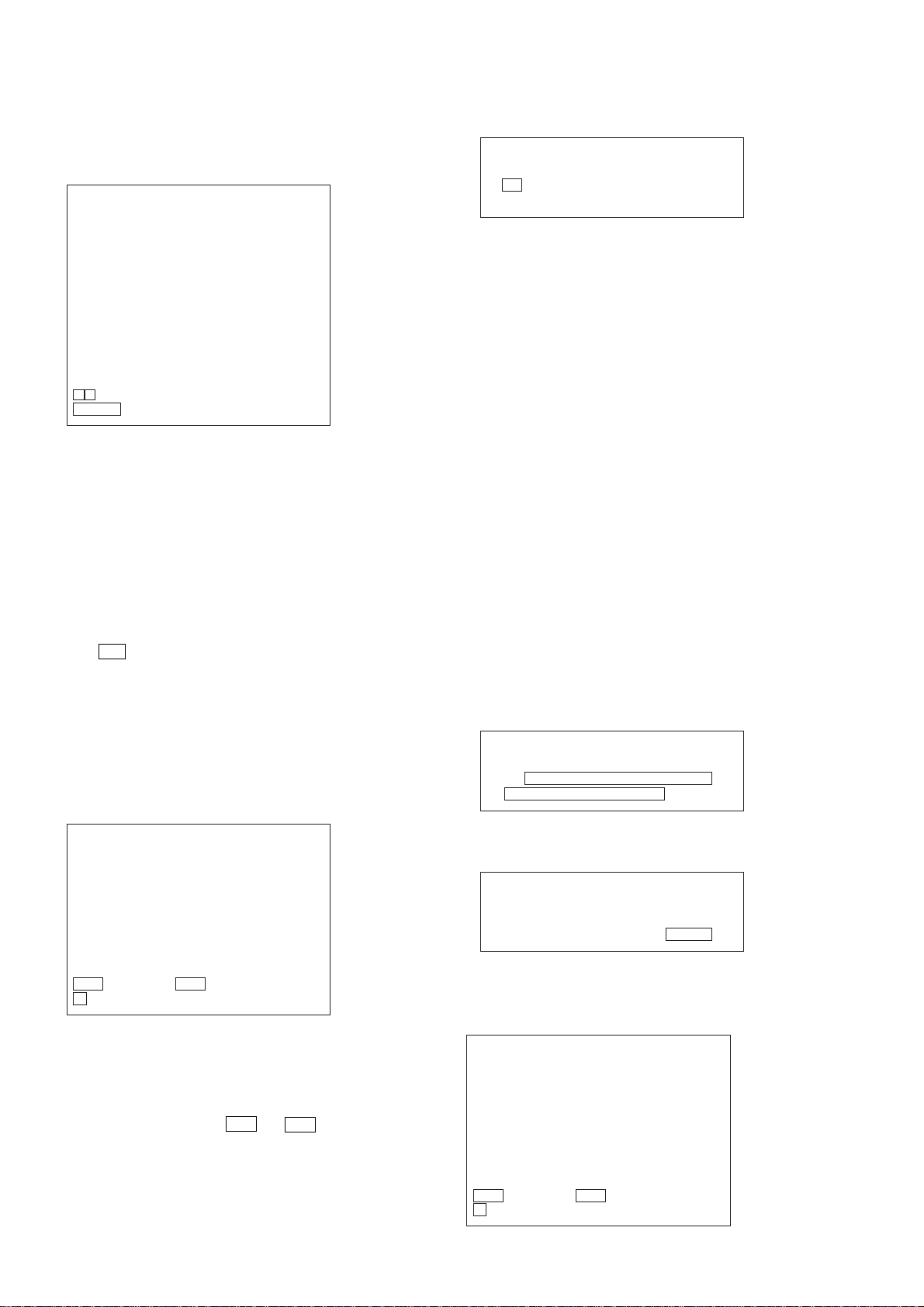
SECTION 5
IC102
IC101
IC104
CN105
CN106
CN105 pin 3 (GND)
CN105 pin
6
(RFMON)
1
6
DMB16 BOARD
(SIDE A)
signal
generator
set
ELECTRICAL ADJUSTMENTS
HCD-GNZ777D/GNZ888D
Ver. 1.1
DVD SECTION
When the optical pick-up assy is replaced, perform the “Execute
IOP Measurement”.
Execute IOP Measurement (See page 25)
[TEST DISC LIST]
Be sure to use the DVD disc that matches the signal standards of
your region.
• CD
YEDS-18 (Part No.: 3-702-101-01)
PATD-012 (Part No.: 4-225-203-01)
• DVD SL (Single Layer)
NTSC : HLX-503 (Part No.: J-6090-069-A)
HLX-504 (Part No.: J-6090-088-A)
PAL : HLX-506 (Part No.: J-6090-077-A)
• DVD DL (Dual Layer)
NTSC : HLX-501 (Part No.: J-6090-071-A)
HLX-505 (Part No.: J-6090-089-A)
PAL : HLX-507 (Part No.: J-6090-078-A)
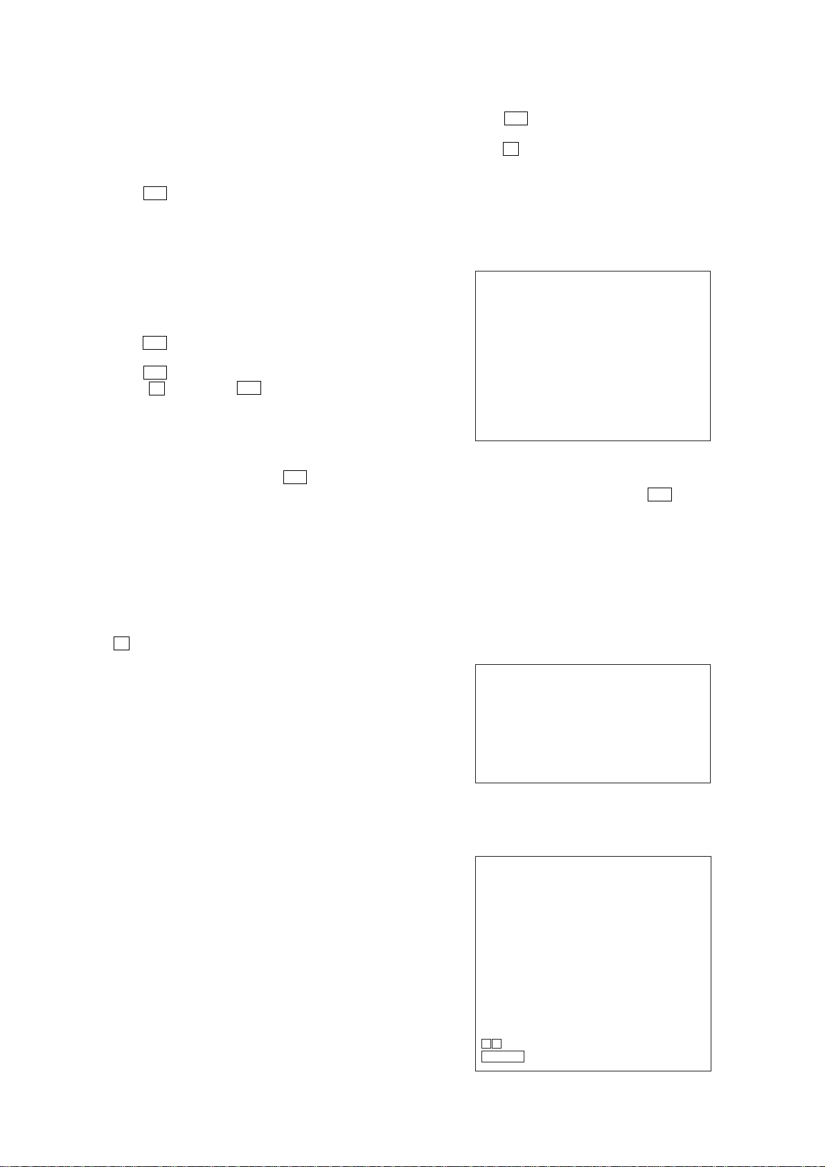
[RFMON Level Check]
Connection:
oscilloscope
DMB16 board
CN105 pin 6 (RFMON)
CN105 pin
3
(GND)
+
–
Checking Location: DMB16 board (Side A)
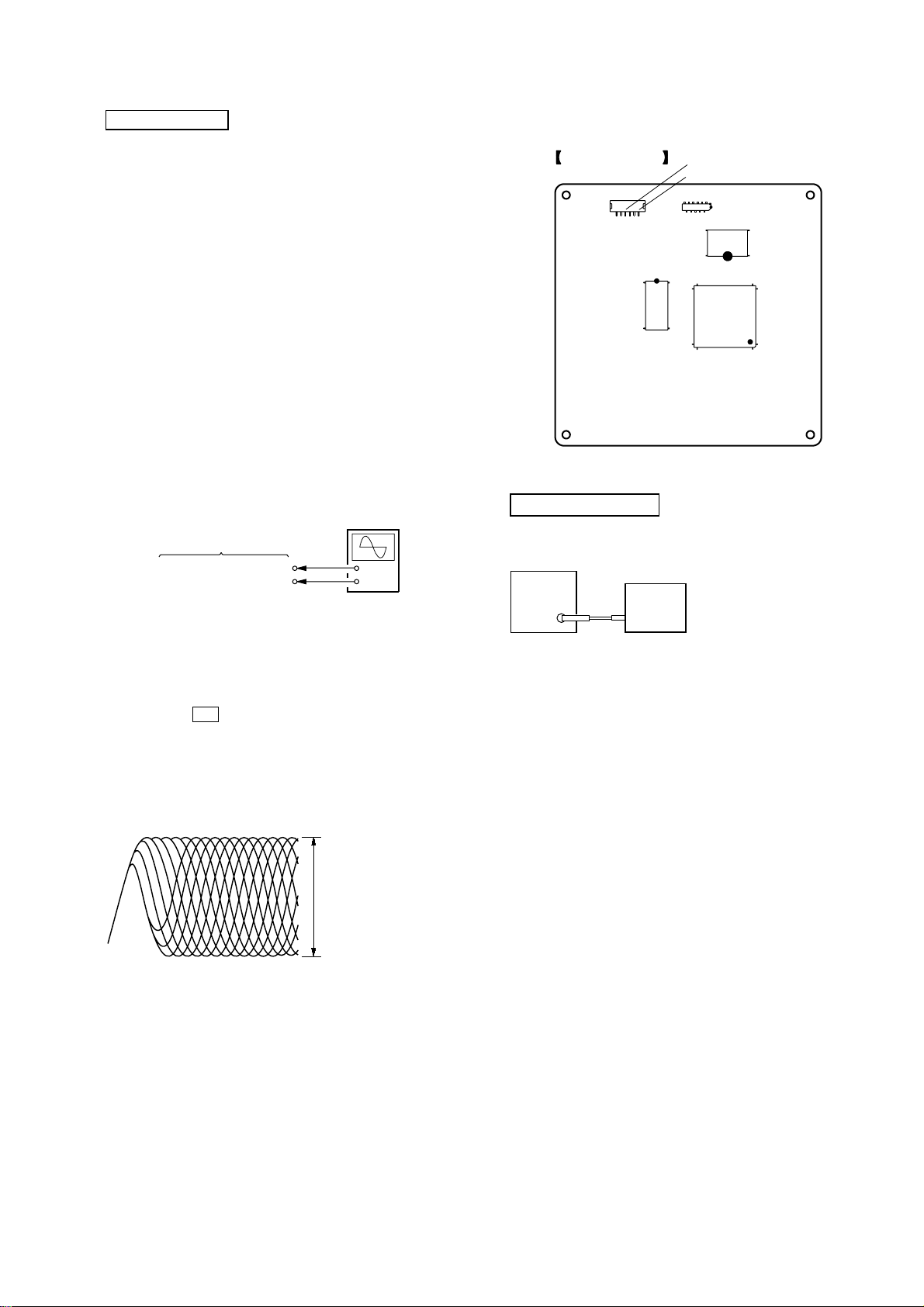
TUNER SECTION
FM TUNE LEVEL CHECK
Procedure:
1. Connect an oscilloscope to CN105 pin 6 (RFMON) and
CN105 pin 3 (GND) on the DMB16 board.
2. Turn the power on.
3. Set the test disc (refer to the TEST DISC LIST) on the tray
and press N button to playback.
4. Confirm that oscilloscope waveform is clear and check
RFMON signal level is correct or not.
Note: A clear RFMON signal wav eform means that the shape “◊” can be
clearly distinguished at the center of the waveform.
RFMON signal waveform
VOLT/DIV: 200 mV
TIME/DIV: 500 ns
level: 0.58 ± 1.23 Vp-p (DVD)
0.57 ± 1.1 Vp-p (CD)
Procedure:
1. Turn on the set.
2. Input the following signal from signal generator to FM antenna
input directly.
Carrier frequency: A = 87.5 MHz, B = 98 MHz, C = 108 MHz
Deviation : 75 kHz
Modulation : 1 kHz
ANT input : 35 dBu (EMF)
Note: Use 75 ohm coaxial cable to connect signal generator and the set.
You cannot use video cable for checking.
Use signal generator whose output impedance is 75 ohm.
3. Set to FM tuner function and tune A, B and C signals.
4. Confirm “TUNED” is lit on the display for A, B and C signals.
When the selected station signal is received in good condition,
“TUNED” is displayed.
29

HCD-GNZ777D/GNZ888D
r
VIDEO SECTION
Video Level Check (VIDEO BOARD)
Purpose
This adjustment is made to satisfy the NTSC standard, and if not
adjusted correctly, the brightness will be too large or small.
oscilloscope
75
Ω
set
J1902
VIDEO OUTPUT
Procedure:
1. Connect oscilloscope to VIDEO output.
2. Load a DVD reference disc playback.
3. Check the video signal level is 1.00±0.07Vp-p.
1.00 ± 0.07 Vp-p
(WHITE 100%)
DECK SECTION
0 dB=0.775 V
1. Demagnetize the record/playback head with a head
demagnetizer.
2. Do not use a magnetized screwdriver for the adjustments.
3. After the adjustments, apply suitable locking compound to the
parts adjust.
4. The adjustments should be performed with the rated power
supply voltage unless otherwise noted.
5. The adjustments should be performed in the order given in this
service manual. (As a general rule, playback circuit adjustment
should be completed before performing recording circuit
adjustment.)
6. The adjustments should be performed for both L-CH and RCH.
7. Switches and controls should be set as follows unless otherwise
specified.
•Test Tape
Tape Signal Used for
P-4-A063 6.3 kHz, –10 dB Azimuth Adjustment
Record/Playback Head Azimuth Adjustment
DECK A DECK B
Note: Perform this adjustments for both decks
Procedure:
1. Mode: Playback
test tape
P-4-A063
(6.3 kHz, –10 dB)
MAIN board
IC101
Pin 28 (L-CH)
Pin 37 (R-CH)
set
MAIN board
IC101
Pin 36 (GND)
level mete
+
–
2. Turn the adjustment screw and c heck output peaks. If the peaks
do not match for L-CH and R-CH, turn the adjustment screw
so that outputs match within 1dB of peak.
output
level
within
1dB
L-CH
peak
R-CH
peak
within
1dB
screw
position
L-CH
peak
screw
position
R-CH
peak
30
 Loading...