

Sony HCD-GNX660 Service Manual
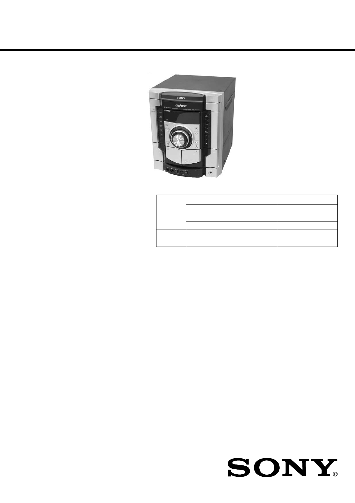
HCD-GNX660
SERVICE MANUAL
Ver. 1.2 2007.12
• HCD-GNX660 is the Amplifier,
CD player, tape deck and tuner
section in MHC-GNX660.
Model Name Using Similar Mechanism HCD-GNX880
CD CD Mechanism Type CDM74KFS-F1BD84
Section Base Unit Name BU-F1BD84
Optical Pick-up Name KSM-215DCP/C2NP
TAPE Model Name Using Similar Mechanism HCD-GNX880
Section Tape Transport Mechanism Type CWN42FF601
Mexican Model
Amplifier section
The following are measured at 127 V AC, 60 Hz
Front speakers
DIN power output (rated) 130 + 130 watts
(6 ohms at 1 kHz, DIN)
Continuous RMS power output (reference)
160 + 160 watts
(6 ohms at 1 kHz, 10% THD)
Sub woofer
Continuous RMS power output (reference)
200 watts
(4 ohms at 100 Hz, 10% THD)
TV (AUDIO) IN (phono jack) voltage 250 mV,
impedance 47 kiloohms
MIC (phone jack) sensitivity 1 mV,
impedance 10 kiloohm
VIDEO OUT (phono jack) max. output level
1 Vp-p, unbalanced, Sync
negative, load impedance
75 ohms
PHONES (stereo mini jack) accepts headphones o
8 ohms or more
FRONT SPEAKER/SUB WOOFER OUT
Use only the supplied
speaker
SPECIFICATIONS
Disc player section
System Compact disc and digital
audio system
Laser Semiconductor laser
(λ=780 nm)
Emission duration:
continuous
Laser Output Max. 44.6 µW*
* This output is the value
measured at a distance of
200 mm from the objective
lens surface on the Optical
Pick-up Block with 7 mm
aperture.
Frequency response 2 Hz – 20 kHz (±0.5 dB)
Wave length 780 – 790 nm
Signal-to-noise ratio More than 90 dB
Dynamic range More than 90 dB
Tape deck section
Recording system 4-track 2-channel stereo
Frequency response 50 – 13,000 Hz (±3 dB),
using Sony TYPE I tape
– Continued on next page –
9-887-203-03
2007L02-1
© 2007.12
MINI HI-FI COMPONENT SYSTEM
Sony Corporation
Audio Business Group
Published by Sony Techno Create Corporation
HCD-GNX660
Tuner section
FM stereo, FM/AM superheterodyne tuner
FM tuner section
Tuning range 87.5 – 108.0 MHz
Antenna FM lead antenna
Antenna terminals 75 ohm unbalanced
Intermediate frequency 10.7 MHz
AM tuner section
Tuning range 530 – 1,710 kHz
(with the interval set at 10 kHz)
531 – 1,710 kHz
(with the interval set at 9 kHz)
Antenna AM loop antenna
Antenna terminals External antenna terminal
Intermediate frequency 450 kHz
General
Power requirements 127 V AC, 60 Hz
Power consumption 110 watts
Dimensions (w/h/d) (Approx.) 280 × 326 × 385.5 mm
Mass (Approx.) 6.3 kg
Supplied accessories: Remote Commander (1)
Batteries (2)
AM loop antenna (1)
FM lead antenna (1)
Front speaker pads (8)
Sub woofer pads (4)
Video cord (1)
Design and specifications are subject to change
without notice.
Notes on chip component replacement
• Never reuse a disconnected chip component.
• Notice that the minus side of a tantalum capacitor may be
damaged by heat.
Flexible Circuit Board Repairing
• Keep the temperature of soldering iron around 270˚C
during repairing.
• Do not touch the soldering iron on the same conductor of the
circuit board (within 3 times).
• Be careful not to apply force on the conductor when soldering
or unsoldering.
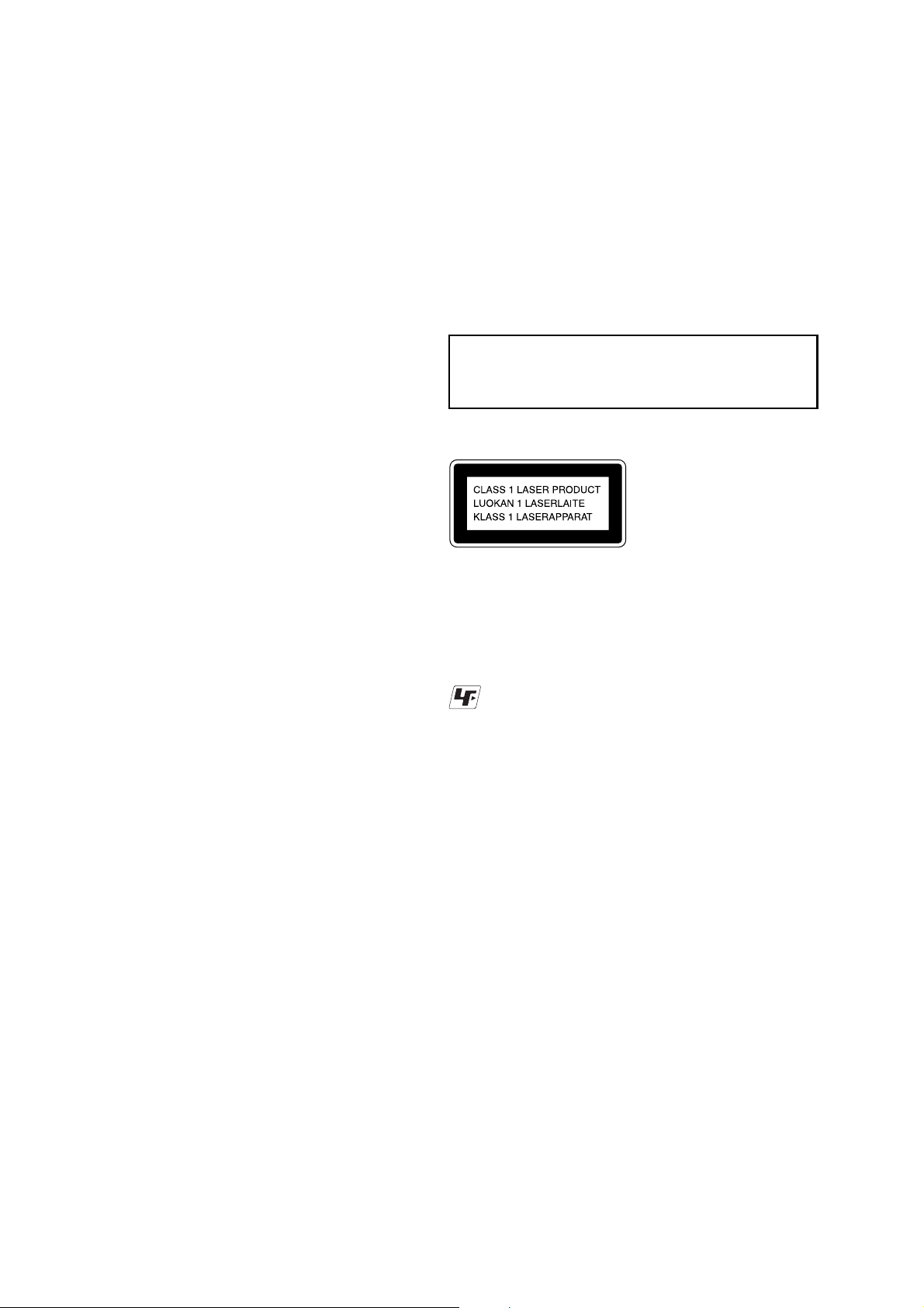
CAUTION
Use of controls or adjustments or performance of procedures
other than those specified herein may result in hazardous
radiation exposure.
This appliance is classified as
a CLASS 1 LASER product.
This label is located on the rear
exterior.
Unleaded solder
Boards requiring use of unleaded solder are printed with the lead
free mark (LF) indicating the solder contains no lead.
(Caution: Some printed circuit boards may not come printed with
the lead free mark due to their particular size.)
: LEAD FREE MARK
Unleaded solder has the following characteristics.
• Unleaded solder melts at a temperature about 40 °C higher than
ordinary solder.
Ordinary soldering irons can be used but the iron tip has to be
applied to the solder joint for a slightly longer time.
Soldering irons using a temperature regulator should be set to
about 350°C.
Caution: The printed pattern (copper foil) may peel away if
the heated tip is applied for too long, so be careful!
• Strong viscosity
Unleaded solder is more viscous (sticky, less prone to flow)
than ordinary solder so use caution not to let solder bridges
occur such as on IC pins, etc.
• Usable with ordinary solder
It is best to use only unleaded solder but unleaded solder may
also be added to ordinary solder.
SAFETY-RELATED COMPONENT WARNING!!
COMPONENTS IDENTIFIED BY MARK 0 OR DOTTED LINE WITH
MARK 0 ON THE SCHEMATIC DIAGRAMS AND IN THE PARTS
LIST ARE CRITICAL TO SAFE OPERATION. REPLACE THESE
COMPONENTS WITH SONY PARTS WHOSE PART NUMBERS
APPEAR AS SHOWN IN THIS MANUAL OR IN SUPPLEMENTS
PUBLISHED BY SONY .
2

TABLE OF CONTENTS
HCD-GNX660
1. SERVICING NOTES ................................................ 4
2. GENERAL
Locating the Controls ...................................................... 5
Setting the Clock ............................................................. 6
3. DISASSEMBLY
3-1. Disassembly Flow ........................................................... 7
3-2. Side Case, Top Case ........................................................ 8
3-3. Loading Panel.................................................................. 8
3-4. Front Panel Assy.............................................................. 9
3-5. Tuner Pack....................................................................... 9
3-6. Tape Mechanism Deck, MIC Board ................................ 10
3-7. PANEL Board, IR Board, VOL Board ............................ 10
3-8. CD Mechanism Deck ...................................................... 11
3-9. Back Panel, DC FAN (M891) ......................................... 11
3-10. MAIN Board, ADC Board............................................... 12
3-11. POWER Board, SPEAKER Board.................................. 12
3-12. SMASTER Board............................................................ 13
3-13. CDG Board, DRIVER Board, SW Board ....................... 13
3-14. BD84 Board, Optical Pick-up ......................................... 14
3-15. SENSOR Board............................................................... 14
3-16. MOTOR (TB) Board ....................................................... 15
3-17. MOTOR (LD) Board....................................................... 15
4. TEST MODE.............................................................. 16
5. MECHANICAL ADJUSTMENTS ....................... 20
6. ELECTRICAL ADJUSTMENTS
Deck section .................................................................... 20
CD Section ...................................................................... 21
7. DIAGRAMS................................................................. 24
7-1. Block Diagram – CDG Section – ................................... 26
7-2. Block Diagram – Tape/Tuner Section – ......................... 27
7-3. Block Diagram – Main Section – ................................... 28
7-4. Block Diagram – AMP Section – ................................... 29
7-5. Block Diagram – Display/Power Section –.................... 30
7-6. Printed Wiring Board – BD84 Board – .......................... 31
7-7. Schematic Diagram – BD84 Board – ............................. 32
7-8. Printed Wiring Boards – CD Mechanism Sectiom –...... 33
7-9. Schematic Diagram – CD Mechanism Section – ........... 34
7-10. Printed Wiring Board – MAIN Board – ......................... 35
7-11. Schematic Diagram – MAIN Board (1/3) – ................... 36
7-12. Schematic Diagram – MAIN Board (2/3) – ................... 37
7-13. Schematic Diagram – MAIN Board (3/3) – ................... 38
7-14. Printed Wiring Boards – PANEL Section –.................... 39
7-15. Schematic Diagram – PANEL Section –......................... 40
7-16. Printed Wiring Boards
– MIC,VOL and SPEAKER Boards – ............................ 41
7-17. Schematic Diagram
– MIC,VOL and SPEAKER Boards – ............................ 42
7-18. Printed Wiring Board – ADC Board –............................ 43
7-19. Schematic Diagram – ADC Board – .............................. 44
7-20. Printed Wiring Board – SMASTER Board (Side A)–... 45
7-21. Printed Wiring Board – SMASTER Board (Side B)– .... 46
7-22. Schematic Diagram – SMASTER Board (1/2)– ............ 47
7-23. Schematic Diagram – SMASTER Board (2/2)– ............ 48
7-24. Printed Wiring Board – CDG Board – ........................... 49
7-25. Schematic Diagram – CDG Board – .............................. 50
7-26. Printed Wiring Boards – Power Board – ........................ 51
7-27. Schematic Diagram – Power Board – ............................ 52
7-28. IC Pin Function Description............................................ 56
8. EXPLODED VIEWS
8-1. Case (Top), Back Panel Section ...................................... 63
8-2. Front Panel Section ......................................................... 64
8-3. Chassis Section................................................................ 65
8-4. CD Mechanism Deck Section-1 ...................................... 66
8-5. CD Mechanism Deck Section-2 ..................................... 67
9. ELECTRICAL PARTS LIST................................ 68
3

HCD-GNX660
Ver. 1.2
SECTION 1
SERVICING NOTES
NOTES ON HANDLING THE OPTICAL PICK-UP BLOCK
OR BASE UNIT
The laser diode in the optical pick-up block may suffer electrostatic
break-down because of the potential difference generated by the
charged electrostatic load, etc. on clothing and the human body.
During repair, pay attention to electrostatic break-down and also
use the procedure in the printed matter which is included in the
repair parts.
The flexible board is easily damaged and should be handled with
care.
NOTES ON LASER DIODE EMISSION CHECK
The laser beam on this model is concentrated so as to be focused on
the disc reflective surface by the objective lens in the optical pickup block. Therefore, when checking the laser diode emission,
observe from more than 30 cm away from the objective lens.
LASER DIODE AND FOCUS SEARCH OPERA TION CHECK
Carry out the “S curve check” in “CD section adjustment” and check
that the S curve waveform is output several times.
CHANGE OF THE COMBINED BOARD SUFFIX
Suffix of the Main, Panel and Power combined board was changed
from -12 to -13.
Suffix of the SMASTER combined board was changed from -12 to
-13 or -21 (-13 and -21 are the same patterns).
4
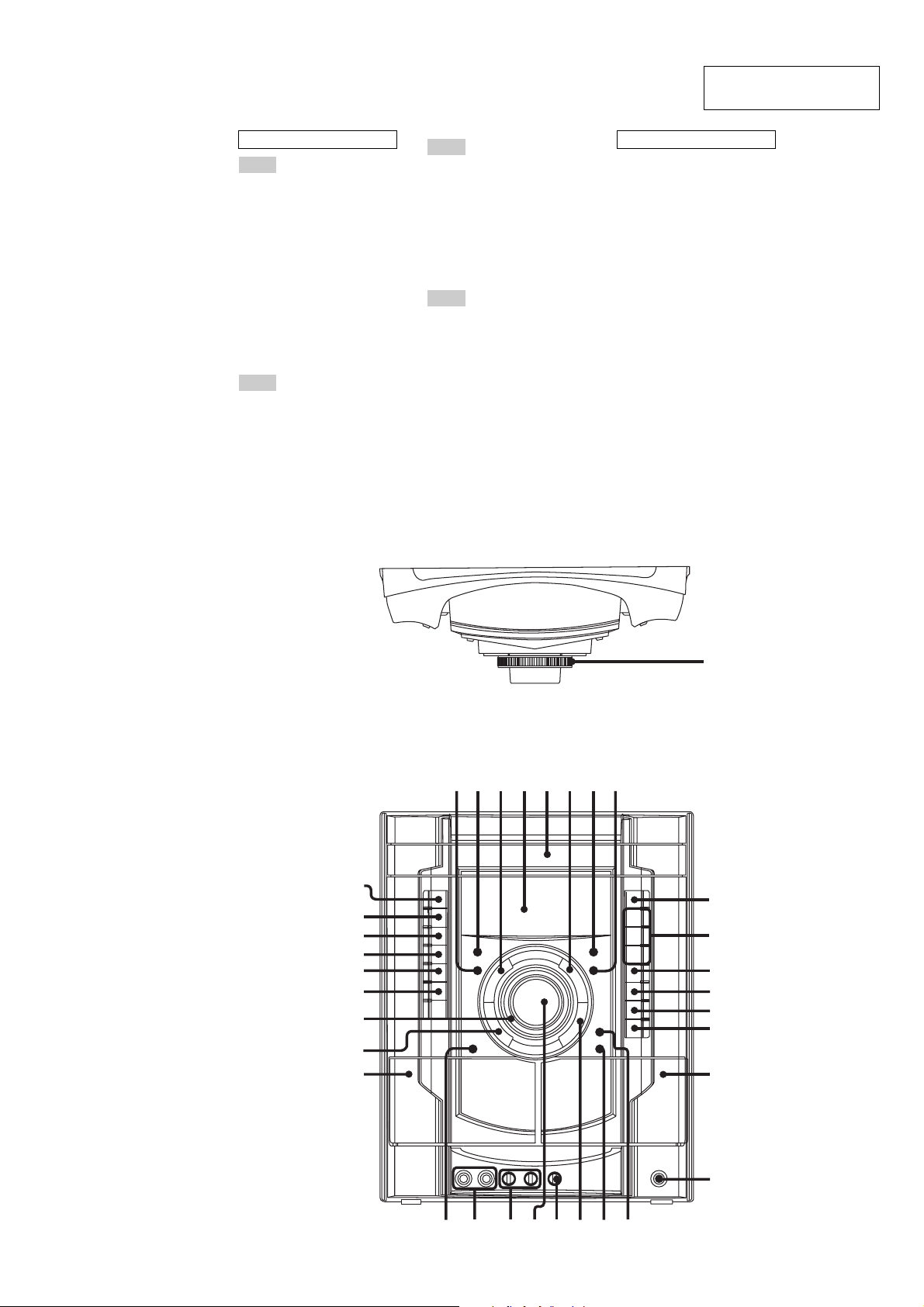
LOCA TING THE CONTROLS
w
q
w
q
w
w
w
w
ALPHABETICAL ORDER
A – D
ALBUM + qk
ALBUM – ql
CD es
CD SYNC 8
Deck A wh
Deck B qh
DIRECTION wg
DISC 1 ~ 3 qa
DISC SKIP/EX-CHANGE qs
Disc tray 6
DISPLAY 3
Display 5
E – L
ECHO LEVEL wa
EQ BAND/MEMORY 4
GROOVE w;
ILLUMINATION/
SUB WOOFER LEVEL 2
SECTION 2
GENERAL
M – R
MASTER VOLUME ws
MIC 1/2 (jack) wf
MIC 1/2 LEVEL wd
MP3 BOOSTER 7
PHONES (jack) qj
POWER ILLUMINATOR wk
PRESET EQ wj
REC PAUSE/START 9
S – Z
SUB WOOFER ON/OFF ed
TAPE A/B e;
Tape lid qh, wh
TUNER/BAND ea
TV wl
HCD-GNX660
This section is extracted
from instruction manual.
SYMBOLS
?/1 (power) ef
Z OPEN/CLOSE q;
N (play) qd
. OPERATION DIAL >
(forward/go backward) 1
M (fast forward) qk
m (rewind) ql
X (pause) qf
x (stop) qg
PUSH Z (Eject A) wh
PUSH Z (Eject B) qh
KARAOKE wg
Top Panel
Front Panel
ef
ed
es
ea
e;
wl
wk
wj
wh
54326
789
1
q;
qa
qs
qd
qf
qg
qh
qj
g
d
f
s
;
a
k
l
5
HCD-GNX660
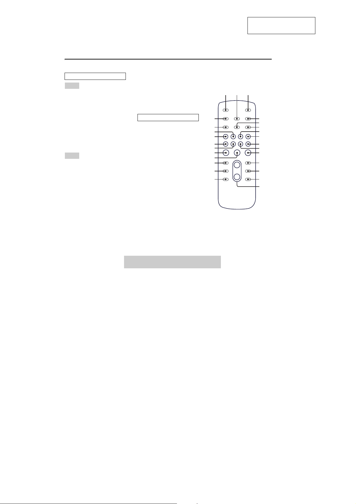
Remote control
ALPHABETICAL ORDER
A – E
ALBUM + qf
ALBUM – qh
CD wf
CLEAR qk
CLOCK/TIMER SELECT 2
CLOCK/TIMER SET 4
DISC SKIP qd
DISPLAY wh
ENTER qs
EQ qj
F – Z
FM MODE 6
FUNCTION 8
PLAY MODE 5
REPEAT 6
SLEEP 1
TAPE wd
TUNER/BAND 7
TUNER MEMORY wg
TUNING MODE 5
VOLUME +/– qg
The + button has a tactile dot.*
SYMBOLS
?/1 (power) 3
x (stop) qa
29, 31)
X (pause) ql
N (play) w;
–. (go backward) ws
>+ (go forward) wa
m (rewind) q;
M (fast forwa rd) 9
*Use the tactile dot as a reference
when operating the system.
This section is extracted
from instruction manual.
12
wh
wg
wf
wd
ws
wa
w;
ql
qk
qj
qh
3
4
5
6
7
8
9
q;
qa
qs
qd
qf
qg
Setting the clock
Use buttons on the remote for the operation.
1
Press ?/1 to turn on the system.
2
Press CLOCK/TIMER SET.
“CLOCK” appears in the display. Then, the
hour indication flashes in the display.
3
Press –. or >+ repeatedly to set
the hour.
4
Press ENTER.
The minute indication flashes in the
display.
5
Press –. or >+ repeatedly to set
the minute.
6
Press ENTER.
The clock starts functioning.
To adjust the clock
1
Press CLOCK/TIMER SET.
“SET” appears in the display, then “PLAY
SET” flashes in the display.
2
Press –. or >+ repeatedly to select
“CLOCK SET”, then press ENTER.
The hour indication flashes in the display.
3
Do the same procedures as step 3 to 6
above.
Notes
The clock settings are canceled when you disconnect
the power cord or if a power failure occurs.
You cannot set the cl ock in Power Saving Mode
(page 23).
6
• This set can be disassembled in the order shown below.
3-1. DISASSEMBLY FLOW
SET
HCD-GNX660
SECTION 3
DISASSEMBLY
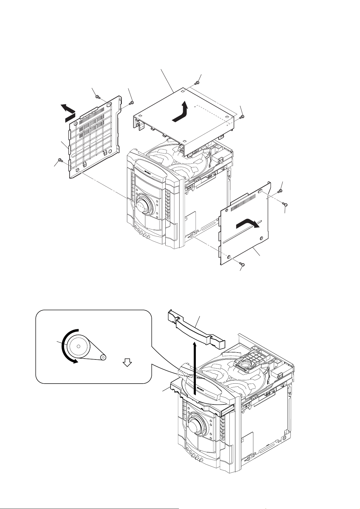
3-2. SIDE CASE, TOP CASE
(Page 8)
3-3. LOADING PANEL
(Page 8)
3-4. FRONT PANEL ASSY
(Page 9)
3-5. TUNER P A CK
(Page 9)
3-8. CD MECHANISM DECK
(Page 11)
3-6. TAPE MECHANISM DECK,
MIC BOARD
(Page 10)
3-7. PANEL BOARD,
IR BOARD,
VOL BOARD
(Page 10)
3-9. BACK PANEL,
DC FAN (M981)
(Page 11)
3-10. MAIN BOARD,
ADC BOARD
(Page 12)
3-11. POWER BOARD,
SPEAKER BOARD
(Page 12)
3-12. SMASTER BOARD,
(Page 13)
3-13. CDG BOARD
DRIVER BOARD,
SW BOARD
(Page 13)
3-14. BD84 BOARD,
OPTICAL PIC-UP
(Page 14)
3-15. SENSOR BOARD
(Page 14)
3-16. MOTOR (TB) BOARD
(Page 15)
3-17. MOTOR (LD) BOARD
(Page 15)
7
HCD-GNX660
Note: Follow the disassembly procedure in the numerical order given.
3-2. SIDE CASE, TOP CASE
7
screw
(case 3 TP2)
(3
×
0
case (side-L)
6
(case 3 TP2)
(3
screw
×
8)
12)
9
8
screw
(+BVTP 3
qf
×
8)
case (top)
qd
qs
two screws
(+BVTP 3
×
8)
qa
two tapping screws
3
screw
(+BVTP 3
×
8)
3-3. LOADING PANEL
CD mechanism deck (CDM74KFS-F1BD84)
1
Turn the pulley to the arrow direction.
Pulley
Front side
3
4
loading panel
4
5
case (side-R)
1
screw (case 3 TP2)
(3
×
8)
2
screw
(case 3 TP2)
(3
×
12)
2
Pull out disc tray.
8
3-4. FRONT PANEL ASSY
)
8
connector
(CN131)
9
connector
(CN205)
3
tapping screw
7
connector
(CN121)
6
wire (flat type)
(CN509)
5
wire (flat type)
(CN201)
q;
connector
(CN503)
HCD-GNX660
4
front panel assy
3-5. TUNER P ACK
2
wire (flat type)
(CN1)
2
tapping screw
1
four screws
(+BVTP 3
3
tuner pack
×
8)
1
two screws
(+BVTT 3
×
6
9
HCD-GNX660
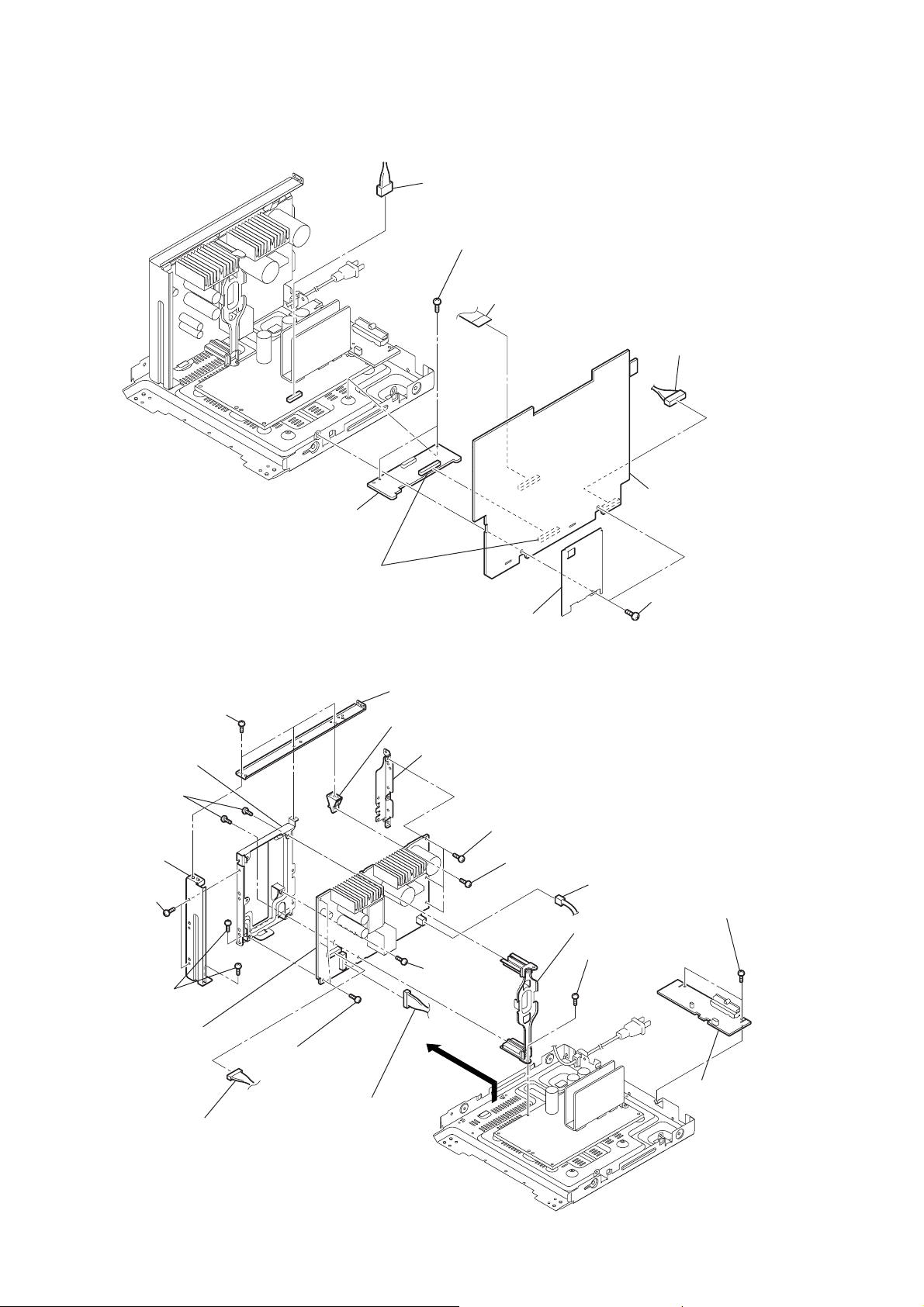
3-6. TAPE MECHANISM DECK, MIC BOARD
front panel
6
holder (TC-L)
5
holder (TC-R)
7
three
mic knobs
2
tape mechanism deck
0
lug
8
four screws
(+BVTP2.6)
9
(pivot)
qs
(TC)
1
(+BVTP2.6)
bracket
bracket
six screws
4
splring (L)
3
spring (R)
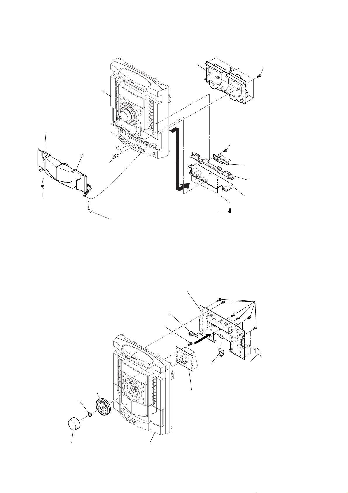
3-7. PANEL BOARD, IR BOARD, VOL BOARD
6
7
four screws
(+BVTP2.6)
IR board
qa
three screws
(+BVTP3
5
PANEL board
2
×
8)
4
connector
(CN1452)
qd
MIC board
1
eighteen screws
(+BVTP2.6)
3
wire (flat type)
(CN1402)
10
8
accessory nut
7
knob (vol)
9
knob jog assy
front panel
0
VOL board
3-8. CD MECHANISM DECK
)
1
CD mechanism deck
4
wire (flat type)
(CN1001)
(CDG board)
5
connector
(CN1003)
(CDG board)
2
wire (flat type)
(CN351)
3
wire (flat type)
(CN701)
HCD-GNX660
3-9. BACK PANEL, DC FAN (M891)
9
connector
(CN580)
4
screw
(+BVTP 3
5
two screws
(+BVTP 3
8
DC fan
(M891)
MAIN board
×
8)
×
8)
6
back panel
1
screw
(+BVTP 3
7
(+BVTP 3
2
three screws
(+BVTP 3
3
three screws
(+BVTP 3
×
8)
two screws
×
8)
×
8)
×
8
11
HCD-GNX660
r
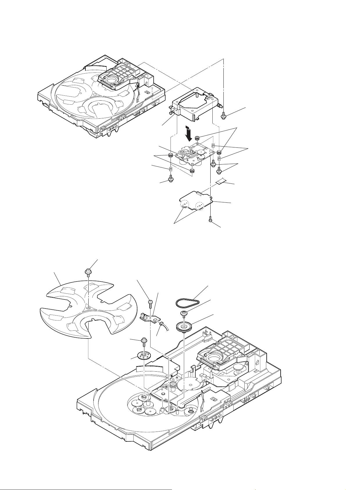
3-10. MAIN BOARD, ADC BOARD
2
connector
(CN501)
3
(+BVTT 3
two screws
1
wire (flat type)
(CN105)
×
6)
7
connecto
(CN590)
9
ADC board
8
board to board connector
(CN381,CN01)
3-11. POWER BOARD, SPEAKER BOARD
7
three screws
(+BVTP 3
qj
bracket (SMPS 5ch)
qd
two tapping screws
q;
bracket
(support front)
9
two screws
(+BVTP 3
2
(+BVTT 3
×
three screws
w;
POWER board
8)
×
6)
×
8)
5
connector
(CN1101)
qh
three screws
(+BVTP 3
5
shield plate (TC MAIN)
8
bracket (support top)
qs
bracket (support pwb)
ql
qg
(+BVTP 3
×
8)
6
connector
(CN1200)
bracket (SMPS -B5)
qk
three screws (+BVTP 3×8)
qa
tapping screw
screw
3
×
8)
4
connector
(CNP1100)
qf
bracket (trans 5ch)
1
screw
(+BVTT 3
6
MAIN board
4
two screws
(+BVTP 3
×
6)
ws
×
8)
wa
two screws
(+BVTP 3
SPEAKER board
×
8)
12
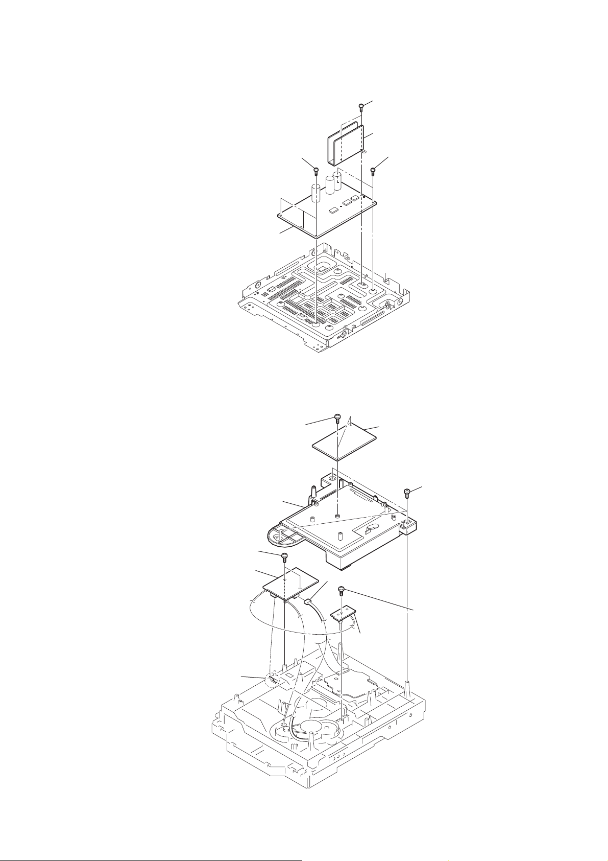
3-12. SMASTER BO ARD
)
4
(+BVTT 3
5
SMASTER board
three screws
×
HCD-GNX660
1
two screws
(+BVTT 3
2
heat sink (SMAS)
6)
3
(+BVTT 3
×
6)
two screws
×
6)
3-13. CDG BOARD, DRIVER BOARD, SW BOARD
1
two
screws
5
two
(+BTTP (M2.6))
8
DRIVER
6
wire (flat type) (CN702)
4
cover (CDM)
screws
board
(+BVTP 3
×
10)
7
connector (CN703)
0
SW board
2
CDG
board
3
(+BVTP 3
9
screw
(+BTTP (M2.6))
three
screws
×
10
13
HCD-GNX660
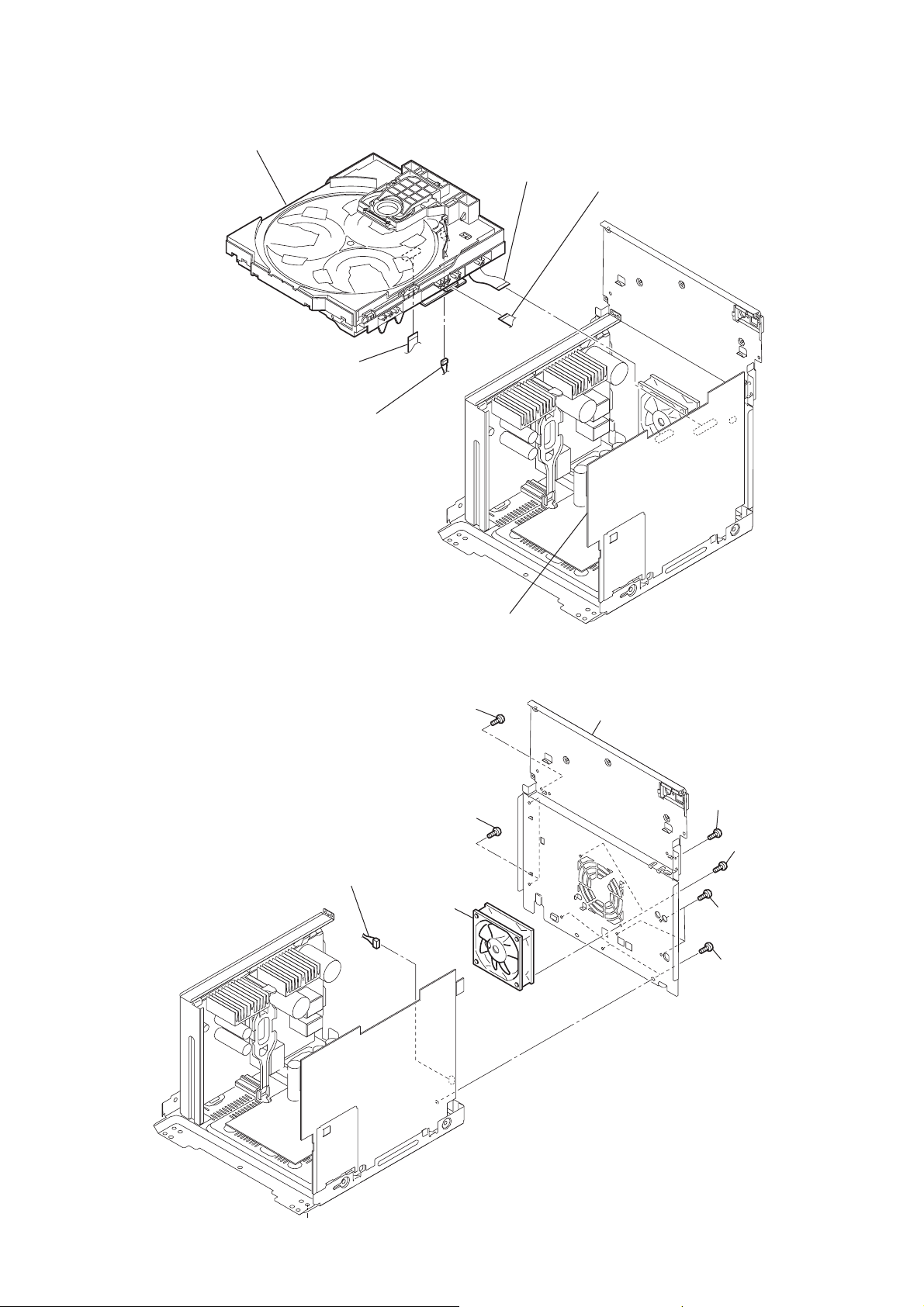
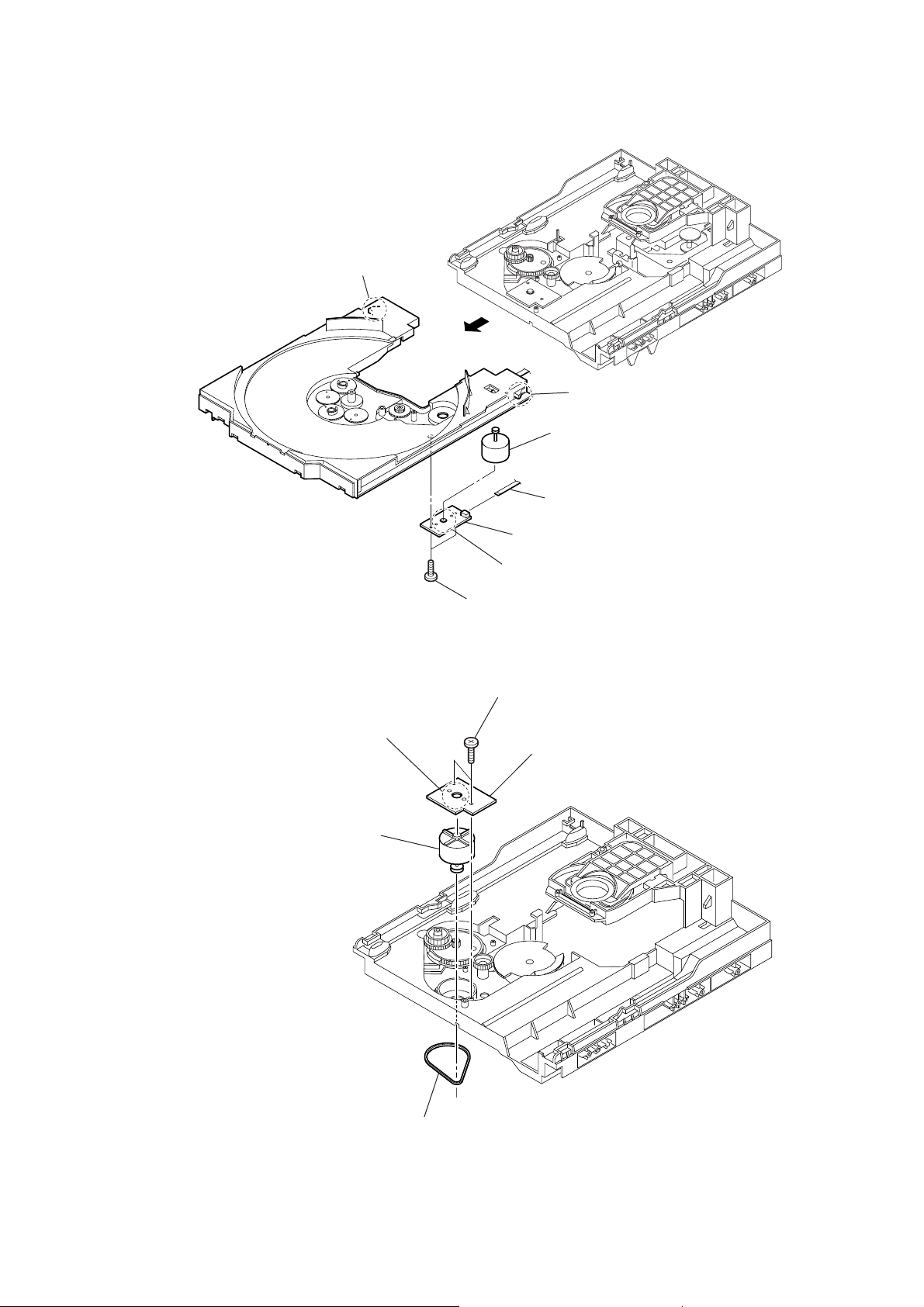
3-14. BD84 BOARD, OPTICAL PICK-UP
qf
optical pick-up
(KSM-215DCP/C2NP)
8
7
(insulator)
2
two
two
coil springs
h
older (213) ASSY
insulators
9
1
floating
(+PTPWH M2.6)
5
two
4
(insulator)
3
two floating
(+PTPWH M2.6)
screw
insulators
two
coil springs
screws
3-15. SENSOR BOARD
2
t
ray
6
two floating
(+PTPWH M2.6)
qa
Remove the four solderings of motor.
1
floating
(+PTPWH M2.6)
6
floating
(+PTPWH M2.6)
screw
8
s
(+BTTP (M2.6))
screw
crew
screws
9
(
0
SENSOR board
connector
CN731)
qs
(CN101)
qd
BD84
q;
s
crew (+BVTP 2.6 (3CR))
3
b
elt (table)
4
floating
(+PTPWH M2.6)
5
screw
p
ulley (table)
wire (flat type)
board
14
7
g
ear (geneva)
3-16. MOTOR (TB) BOARD
2
stopper
4
1
stopper
7
t
able motor assy (M741)
HCD-GNX660
3-17. MOTOR (LD) BOARD
4
Remove the two solderings of motor.
5
l
oading motor assy (M751)
3
8
MOTOR (TB) board
6
Remove the two solderings of motor.
5
two
screws
(+BTTP (M2.6))
2
two
screws
(+BTTP (M2.6))
3
MOTOR (LD) board
wire (flat type) 5 core (CN742)
1
b
elt (loading)
15

HCD-GNX660
[P ANEL TEST MODE]
• This mode is used to check the fluorescent indicator tube,
LEDs, buttons, MASTER VOLUME knob, model,
destination, software version and VACS level.
SECTION 4
TEST MODE
[COMMON TEST MODE]
• This mode is used to check operations of the respective sections
of Amplifier and T ape.
Procedure:
1. Press x button, [ILLUMINATION] button and [DISC 2]
button simultaneously.
2. All LEDs and segments in fluorescent indicator tube are lighted
up. All LEDs are lighted up in red color except the SUB
WOOFER ON/OFF LED (green).
3. When you want to enter to the software version display mode,
press [DISC 1] button. The model infomation is displayed.
Press [DISC 1] button again to view destination infomation.
4. Each time [DISC 1] button is pressed, the display changes from
MC version, SYS version, UI version, CD version, CDDM
version, CDMA version, CDMB version, BDA version, BDB
version, ST version, TA version, TM version, TC version in
this order, and returns to the model version display.
5. When [DISC 3] button is pressed while the version numbers
are being displayed except model and destination, the date of
the software creation appear. When [DISC 3] button is pressed
again, the display returns to the software version display. When
[DISC 1] button is pressed while the date of the software
creation is being displayed, the date of the software creation
is displayed in the same order of software version display.
6. Press [DISC 2] button, the key check mode is activated.
7. In the key check mode, the fluorescent indicator tube displays
“K 0 V0”. T urn the [OPERATION DIAL] clockwise, “K” value
increases by one. Turn the [OPERATION DIAL] counterclockwise, “K” value increases by one. Each time a button is
pressed, “K” value increases. Press other buttons on main unit
to check whether the button is detected. However, once a button
has been pressed, it is no longer taken into account.
“V” value increases in the manner of 0,1, 2, 3 ... if [MASTER
VOLUME] knob is turned clockwise, or it decreases in the
manner of 0, 9, 8, 7 ... if [MASTER VOLUME] knob is turned
counter-clockwise.
8. When [DISC 3] button is pressed after all LEDs and segments
in fluorescent indicator tube light up, the fluorescent indicator
tube displays “VACS A”. A is VACS level which is trigger by
signal level.
9. When [DISC SKIP/EX-CHANGE] button is pressed after all
LEDs and segments in fluorescent indicator tube light up,
alternate segments in fluorescent indicator tube would light
up. If you press [DISC SKIP/EX-CHANGE] button again, another
half of alternate segments in fluorescent indicator tube would
light up. When [DISC SKIP/EX-CHANGE] button is pressed
again, all segments lights off. Press [DISC SKIP/EX-CHANGE]
button again would cause all segments lights up.
10. To release from this mode, press three buttons in the same
manner as step 1, or disconnect the power plug.
Procedure:
* To enter Common Test Mode
1. Press x button, [ILLUMINATION] button and [DISC 3]
button simultaneously.
2. The CD ring indicators and line below CD ring indicator flash
synchronously on the fluorescent indicator tube. The function
is changed to TV.
* Check of Amplifier
1. Press [EQ BAND/MEMORY] button repeatedly until a message
“GEQ MAX” appears on the fluorescent indicator tube. GEQ
increases to its maximum.
2. Press [EQ BAND/MEMORY] button repeatedly until a message
“GEQ MIN” appears on the fluorescent indicator tube. GEQ
decreases to its minimum.
3. Press [EQ BAND/MEMORY] button repeatedly until a message
“GEQ FLA T” appears on the fluorescent indicator tube. GEQ
is set to flat.
4. When the [MASTER VOLUME] knob is turned clockwise even
slightly, the sound volume increases to its maximum and a
message “VOLUME MAX” appears on the fluorescent
indicator tube.
5. When the [MASTER VOLUME] knob is turned counterclockwise even slightly, the sound volume decreases to its
minimum and a message “VOLUME MIN” appears on the
fluorescent indicator tube.
* Tape function
1. When a tape is inserted in Deck B and recording is started, the
function is changed to TV automatically. When [CD SYNC]
button is pressed during recording in function, ALC
(Automatic Logic Control) is turned on.
2. During recording, press
and the function is changed to T APE B and rewind the tape in
Deck B until the recording start position and playback of the
tape in Deck B is started. If the [REC PAUSE/ START] button
is pressed for a pause and pressed again to resume recording
during recording time, when the tape is rewind, the tape will
be rewind until the position where the pause is applied.
* To release from Common Test mode.
1. To release this mode, press
2. The cold reset is enforced at the same time.
[COLD RESET]
• The cold reset clears all data including preset data stored in
the RAM to initial conditions. Execute this mode when
returning the set to the customer.
button will stop the recording
m
button.
?/1
16
Procedure:
1. Press button to turn on the set.
2. Press x button, [ILLUMINATION/SUB WOOFER LEVEL]
3. The message “COLD RESET” appears on the fluorescent
?/1
button, and
indicator tube. then, the fluorescent indicator tube becomes
blank for a while, and the set is reset.
button simultaneously.
?/1
[VACS ON/OFF]
• This mode is used to switch ON and OFF the VACS (Variable
Attenuation Control System).
Procedure:
1. Press
2. Press x button and [DIRECTION]
simultaneously.
appears on the fluorescent indicator tube.
[TUNER STEP CHANGE]
• The step interval of AM channels can be toggled between 9
kHz and 10 kHz.
Procedure:
1. Press
2. Press [TUNER/BAND] button repeatedly to select the “AM”.
3. Press
4. Press [ILLUMINATION/SUB WOOFER LEVEL] button and
?/1
automatically. The message “AM 9K STEP” or AM 10K
STEP” appears on the fluorescent indicator tube and thus the
channel step is changed.
button to turn on the set.
?/1
button
and [DISC 1]
The message “VACS OFF” or “VACS ON”
button to turn on the set.
?/1
button to turn off the set.
?/1
button simultaneously. The system will turn on
button
HCD-GNX660
[CD AGING MODE]
This mode can be used for operation check of CD section.
• If an error occurs, the aging operation would stops and the
status is displayed.
• If there were no error occurs, the aging operation would
continue repeatedly.
Procedure:
1. Press
2. Select CD function.
3. Load three discs on the disc tray.
4. Press [PLAY MODE] button on the remote repeatedly to select
the “ALL DISCS” mode, and press the [REPEAT] button on
the remote repeatedly to select “REPEAT OFF” mode.
5. Press x button, [ILLUMINATION/SUB WOOFER LEVEL]
button, and[DISC SKIP/EX-CHANGE] button
simultaneously.The CD ring indicator and line below CD
ring indicator turn on afternately to indicate aging mode.
6. Aging operation is started.
7. To release from this mode, press
the power plug.
Aging mode sequence:
button to turn on the set.
?/1
Start (from disc 1)
button or disconnect
?/1
[CD SERVICE MODE]
• This mode let you move the CD sled motor freely. Use this
mode when you want to clean the optical pick-up.
Procedure:
1. Press
2. Select CD function.
3. Press x button, [ILLUMINATION/SUB WOOFER LEVEL]
button and
4. The CD service mode is activated. The message “SERVICE
MODE” appears on the fluorescent indicator tube.
5. With the CD in stop status, press
optical pick-up to outside track, or press
to inside track. The message “SLED OUT” or “SLED IN”
appears on the fluorescent indicator tube.
6. To turn on or off the laser, press [GROOVE] button. The
message “LD ON” or “LD OFF” appears on the fluorescent
indicator tube.
7. To release from this mode, press
button to turn on the set.
?/1
OPEN/CLOSE
Z
button simultaneously.
button to move the
M
button to move
m
button.
?/1
Disc chucking
TOC reading
Play first track for 2 seconds
Play last track for 2 seconds
EX-CHANGE open/close
Open the disc tray
Disc skip
Close the disk tray
Change to the next disc
17
HCD-GNX660
>
.
• Display when an error occurred (CD Error Code Mode)
Procedure:
1. Press x button, [ILLUMINATION/SUB WOOFER
LEVEL] button and [DISC 1] button simultaneously to
enter the error code display mode.
2. The fluorescent indicator tube displays the number of total
error.
3. Each time m or M button is pressed, display change as
below.
Display of total error
>
direction direction
M
>
direction direction
4. To clear the error record, operate the cold reset. (Refer to the
“COLD RESET”)
5. To release from this mode, press the
disconnect the power plug.
1) Display of total error
EM**: The number of mechanical errors.
ED**: The number of no disc errors after chucking the disc.
2) Display of mechanical errors
M m
Display of Mechanical errors
m
Display of no disc errors
Display
EM**ED**
Display
M*$$%%&&##00
?/1
.
.
button or
3) Display of no disc errors
Display
D*$$%%&&##00
D*: The number of no disc error (“00” is latest one)
(Rotate
error)
$$: Error type
01: Focus error
02: GFS error
03: Setup error
%%: Not used
&&:
00: No disc judgment without chucking retry.
01: No disc judgment after chucking retry.
##: The state when judged as no disc
01: Stop
02: Setup
03: TOC reading
04: Access
05: Playback
06: Pause
07: Manual search (Play)
08: Manual search (Pause)
[CD REPEAT 5 LIMIT OFF MODE]
• The number of repeat for CD playback is 5 times when the
repeat mode is “REPEAT ALL”. This mode enables CD to
repeat playback for limitless times.
Procedure:
1. Press
2. Select CD function.
3. Press x button, [CD] button and [DISC 1] button
simultaneously to enter the CD repeat 5 limit off mode and
the fluorescent indicator tube displays “LIMIT OFF”.
4. To release from this mode, operate the cold reset. (Refer to
the “COLD RESET”)
knob in the direction of either to display next
button to turn on the set.
?/1
M*: The number of mechanical error (“00” is latest one)
(Rotate
.
knob in the direction of either to display next
>
error)
$$: Not used
%%: Loading related error (Second figure is not used)
D: Stop by the problem other than mechanical problem while
closing.
E: Stop by the problem other than mechanical problem while
opening.
C: Stop by the problem other than mechanical problem while
chucking up.
F: Stop by the problem other than mechanical problem while
chucking down.
&&: Emerging error
01: Stop while chucking up.
02: Stop while chucking up.
03: Time-out of EX-CHANGE open.
05: Time-out of EX-CHANGE close.
##: Not used
[CD SHIP MODE (WITH MEMORY CLEAR)]
• This mode moves the optical pick-up to the position durable
to vibration and clears all data including preset data stored in
the RAM to initial conditions. Use this mode when returning
the set to the customer after repair.
Procedure:
1. Press
button to turn on the set.
?/1
2. Select CD function.
3. Press x
simultaneously.
button,
[DIRECTION]
button and
The set will turn off automatically.
?/1
button
4. After the “STANDBY” blinking display finishes, a message
“MECHA LOCK” is displayed on the fluorescent indicator
tube and the CD ship mode is set.
18

HCD-GNX660
[CD SHIP MODE (WITHOUT MEMORY CLEAR)]
• This mode moves the optical pick-up to the position durable
to vibration. Use this mode when returning the set to the
customer after repair.
Procedure:
1. Press
2. Select CD function.
3. Press [CD] button and
will turn off automatically.
4. After the “STANDBY” blinking display finishes, a message
“MECHA LOCK” is displayed on the fluorescent indicator
tube and the CD ship mode is set.
[CD POWER MANAGE]
• This mode let you switch on or off power supply to the BU
during TUNER function.
• When CD POWER is set to OFF , the power supply to the BU
is cut off during TUNER function. It will increase the time
taken to access CD when function change from TUNER to
CD but it will improve tuner reception.
• When CD POWER is set to ON, the power supply to the BU
is not cut off during TUNER function. It will reduce the time
taken to access CD when function change from TUNER to
CD but it will decrease tuner reception performance.
Procedure:
1. Press
2. Select CD function.
3. Press
4. Press x button and
will turn on automatically.
5. The message “CD POWER ON” or “CD POWER OFF” will
be displayed on the fluorescent indicator tube.
button to turn on the set.
?/1
?/1
button to turn on the set.
?/1
button to turn off the set.
?/1
?/1
button simultaneously. The set
button simultaneously. The set
[CD TRAY LOCK MODE]
• This mode let you lock the disc tray. When this mode is
activated, the disc tray will not open when
button or [DISC SKIP/EX-CHANGE] button is pressed. The
message “LOCKED” will be displayed on the fluorescent
indicator tube.
Procedure:
1. Press
2. Select CD function.
3. Press x button and
simultaneously and hold down until “LOCKED” or
“UNLOCKED” displayed on the fluorescent indicator tube
(around 5 seconds).
[TCM OFFLINE MODE]
• This mode prevents set from power off automatically when
TCM is not connected.
Therefore, measurements can be done even when TCM is not
connected during production.
• Procedure:
1. When the set in turned off, press [EQ BAND/MEMORY]
button, [TAPE A/B] button and
The set will turn on automatically.
2. The message “TCM OFFLINE” will be displayed on the
fluorescent indicator tube.
button to turn on the set.
?/1
Z
OPEN/CLOSE
?/1
OPEN/CLOSE
Z
button
button simultaneously .
19
HCD-GNX660
SECTION 5
MECHANICAL ADJUSTMENTS
Precaution
1. Clean the following parts with a denatured alcohol-moistened
swab:
record/playback heads pinch rollers
erase head rubber belts
capstan idlers
2. Demagnetize the record/playback head with a head
demagnetizer.
3. Do not use a magnetized screwdriver for the adjustments.
4. After the adjustments, apply suitable locking compound to
the parts adjusted.
5. The adjustments should be performed with the rated power
supply voltage unless otherwise noted.
Torque Measurement
Mode Torque meter Meter reading
2.9 mN • m to 6.9 mN • m
FWD CQ-102C 30 to 70 g • cm
(0.42 – 0.97 oz • inch)
FWD
back tension
FF/REW CQ-201B 49 to 170 g • cm
CQ-102C 1.6 to 6 g • cm
0.15 mN • m to 0.59 mN • m
(0.022 – 0.08 oz • inch)
4.8 mN • m to 16.7 mN • m
(0.69 – 2.36 oz • inch)
SECTION 6
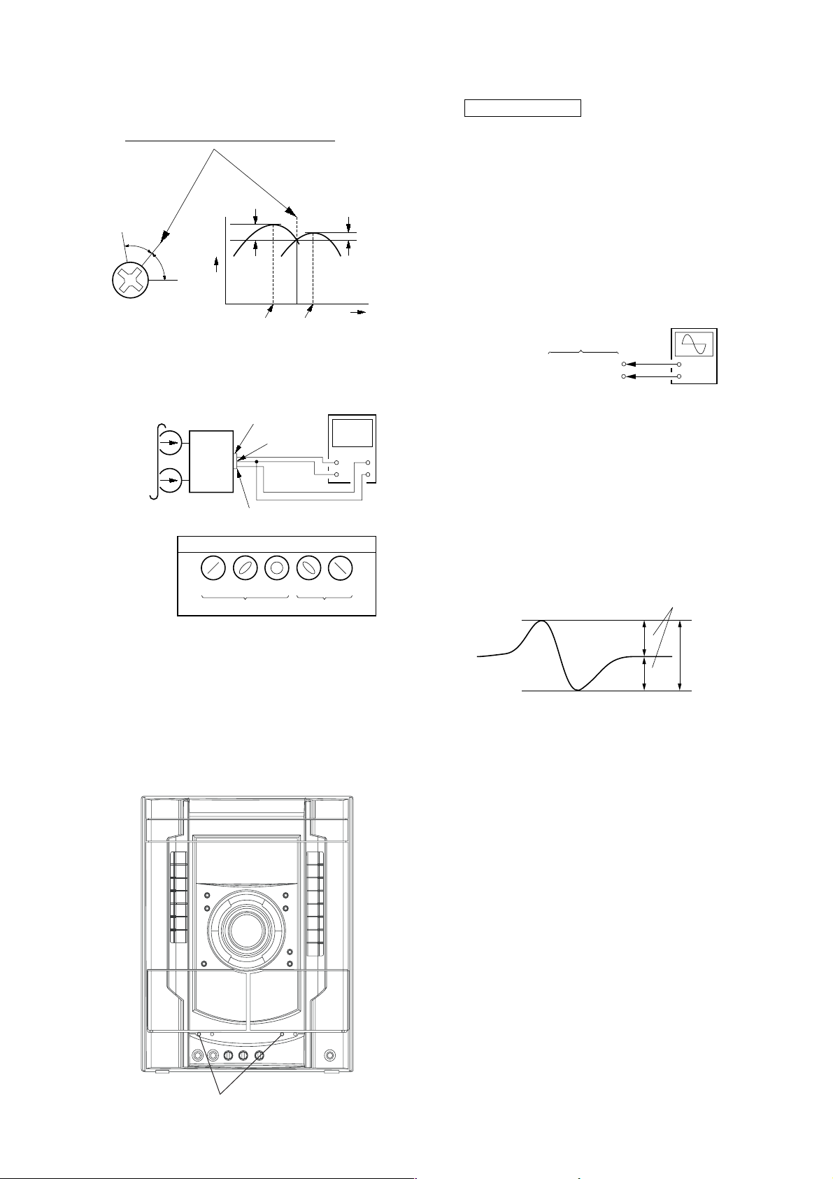
ELECTRICAL ADJUSTMENTS
DECK SECTION
1. Demagnetize the record/playback head with a head
demagnetizer.
2. Do not use a magnetized screwdriver for the adjustments.
3. After the adjustments, apply suitable locking compound to the
parts adjust.
4. The adjustments should be performed with the rated power
supply voltage unless otherwise noted.
5. The adjustments should be performed in the order given in
this service manual. (As a general rule, playback circuit
adjustment should be completed before performing recording
circuit adjustment.)
6. The adjustments should be performed for both L-CH and RCH.
7. Switches and controls should be set as follows unless otherwise
specified.
•Test T ape
Tape Signal Used for
P-4-A100 10 kHz, –10 dB Azimuth Adjustment
RECORD/PLAYBACK HEAD AZIMUTH ADJUSTMENT
DECK A DECK B
0 dB=0.775 V
Note: Perform this adjustments for both decks
Procedure:
1. Mode: Playback
test tape
P-4-A100
(10 kHz, –10 dB)
set
MAIN board
CN121
Pin
3
(L-CH)
Pin
1
(R-CH)
MAIN board
CN121
Pin
2
(GND)
level meter
+
–
20
HCD-GNX660
e
A
B
symmetry
within 2.4
±
1 Vp-p
2. Turn the adjustment screw and check output peaks. If the peaks
do not match for L-CH and R-CH, turn the adjustment screw
so that outputs match within 1dB of peak.
Output
level
within
1dB
L-CH
peak
R-CH
peak
within
1dB
Screw
position
L-CH
peak
Screw
position
R-CH
peak
3. Mode: Playback
test tape
P-4-A100
(10 kHz, –10 dB)
L-CH
MAIN
board
CN121
set
R-CH
waveform of oscilloscope
pin
L
R
pin
3
pin
1
2
oscilloscop
H
V
CDG SECTION
Note:
1. CDG Block is basically designed to operate without
adjustment. Therefore, check each item in order given.
2. Use YEDS-18 disc (3-702-101-01) unless otherwise indicated.
3. Use an oscilloscope with more than 10MΩ impedance.
4. Clean the object lens by an applicator with neutral detergent
when the signal level is low than specified value with the
following checks.
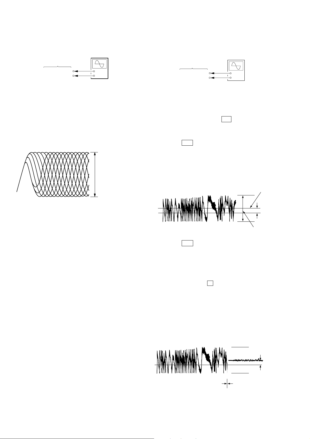
S-curve Check
Connection:
oscilloscope
BD84 board
JPO102 (FE1)
TP117 (VC)
Procedure:
1. Connect an oscilloscope to test point JPO102 (FE1) and TP
117(VC) on the BD84 board.
2. Turn the power on.
3. Put the disc (YEDS-18) in and turned power switch on again
and actuate the focus search. (actuate the focus search when
disc table is moving in and out)
4. Check the oscilloscope waveform (S-curve) is symmetrical
between A and B. And confirm peak to peak level within
2.4 ± 1 Vp-p.
+
–
in phase 45°90°135°180
good
°
wrong
4. After the adjustments, apply suitable locking compound to
the pats adjusted.
Adjustment Location: Playback Head (Deck A).
Record/Playback Head (Deck B).
S-curve waveform
Note:
•Try to measure several times to make sure than the ratio
of A : B or B : A is more than 10 : 7.
•Take sweep time as long as possible and light up the
brightness to obtain best waveform.
Checking Location: BD84 board (SIDE B)
(See page 23.)
azimuth
screw
21
HCD-GNX660
+
–
BD84 board
JPO103 (TE1)
TP117 (VC)
oscilloscope
RFAC Level Check
Connection:
oscilloscope
BD84 board
TP124 (RFAC)
TP117 (VC)
+
–
Procedure:
1. Connect an oscilloscope to test point TP124 (RFAC) and TP
117(VC) on the BD84 board.
2. Turn the power on.
3. Put the disc (YEDS-18) in to playback the number five track.
4. Confirm that oscilloscope waveform is clear and check RFAC
signal level is correct or not.
Note: A clear RFAC signal waveform means that the shape “◊” can be
RFAC signal waveform
clearly distinguished at the center of the waveform.
VOLT/DIV: 200 mV
TIME/DIV: 500 ns
level: 0.9 ± 0.4 Vp-p
E-F Balance Check
Connection:
Procedure:
1. Connect an oscilloscpe to test point TPO103 (TE1) and TP117
(VC) on the BD84 board.
2. Turn the power on.
3. Select the function “CD”.
4. Press three buttons of [ENTER], M , and
[SURRUUND MODE] simultaneously to set the CD service
mode.
5. Put the disc (YEDS-18) in to playback the number five track.
6. Press the . button. The message “TRAVERSE” is
displayed. (The tracking servo and the sledding servo are
turned OFF)
7. Check the level B of the oscilliscope's waveform and the A
(DC voltage) of the center of the Traverse waveform.
Confirm the following :
A/B x 100 = less than ± 22%
Traverse Wa vef orm
Center of
the waveform
Checking Location: BD84 board (SIDE B)
(See page 23.)
B
0V
level: 1.0 ± 0.5 Vp-p
8. Press the . button. The message “TRAVERSE” is
A (DC
voltage)
displayed. (The tracking servo and sledding servo are turned
ON)
Confirm the C (DC voltage) is almost equal to the A (DC
voltage) is step 5.
9. To exit from this mode, perform as follows.
1) Move the optical pick-up to the most inside track.
2)Press three buttons of x , [CLEAR], and [DISPLAY]
simultaneously. (cold reset)
Notes:
• Always move the optical pick-up to most inside track
when exiting from this mode. Otherwise, a disc will not
be unloaded.
• Do not run the sled motor excessively, otherwise the gear
can be chipped.
Traverse Wa vef orm
22
0V
Tracking servo
Sled servo
OFF
Tracking servo
Sled servo
ON
Checking Location: BD84 board (SIDE B) (See page 23.)
C (DC
voltage)
Checking Location:
– BD84 BOARD (SIDE B) –
HCD-GNX660
TP117 (VC)
JPO103 (TE1)
JPO102 (FE1)
IC101
TP124 (RFAC)
23
HCD-GNX660
SECTION 7
DIAGRAMS
For schematic diagrams.
Note:
• All capacitors are in µF unless otherwise noted. (p: pF)
50 V or less are not indicated except for electrolytics and
tantalums.
• All resistors are in Ω and
specified.
•%: indicates tolerance.
• f : internal component.
• 2 : nonflammable resistor.
• 5 : fusible resistor.
Note: The components identified by mark 0 or dotted line
with mark ! are critical for safety.
Replace only with part number specified.
• C : panel designation.
• A : B+ Line.
• B : B– Line.
•Voltages and waveforms are dc with respect to ground
under no-signal conditions.
BD84 board
no mark: CD PLAY
Other boards
no mark: TUNER (FM/AM)
( ) : CD PLAY
< > : TAPE PLAY
[ ] : TAPE REC
* : Impossible to measure
•Voltages are taken with a VOM (Input impedance 10 MΩ).
Voltage variations may be noted due to normal production tolerances.
•Waveforms are taken with a oscilloscope.
Voltage variations may be noted due to normal production tolerances.
• Signal path.
F : AUDIO
f : TUNER (FM/AM)
E : TAPE PLAY (DECK A)
d : TAPE PLAY (DECK B)
G : RECORD
J : CD PLAY
N : MIC INPUT
c : CDG
g : VIDEO
1
4
/
W or less unless otherwise
Note on Printed Wiring Boards:
Note:
• X : parts extracted from the component side.
• : Pattern from the side which enables seeing.
(The other layers' patterns are not indicated.)
Caution:
Parts face side: Parts on the parts face side seen from
(Side A) the parts face are indicated.
Pattern face side: Parts on the pattern face side seen from
(Side B) the pattern face are indicated.
• Indication of transistor.
C
B
B
Q
B
E
Q
CE
Q
CE
These are omitted.
These are omitted.
These are omitted.
24
HCD-GNX660
TUNER pack
MAIN board
SMASTER board
SPEAKER board
ADC board
MIC board
VOL board
PANEL board
POWER board
IR board
MOTOR (LD) board
SW board
SENSOR board
BD84 board
DRIVER board
CDG board
MOTOR (TB) board
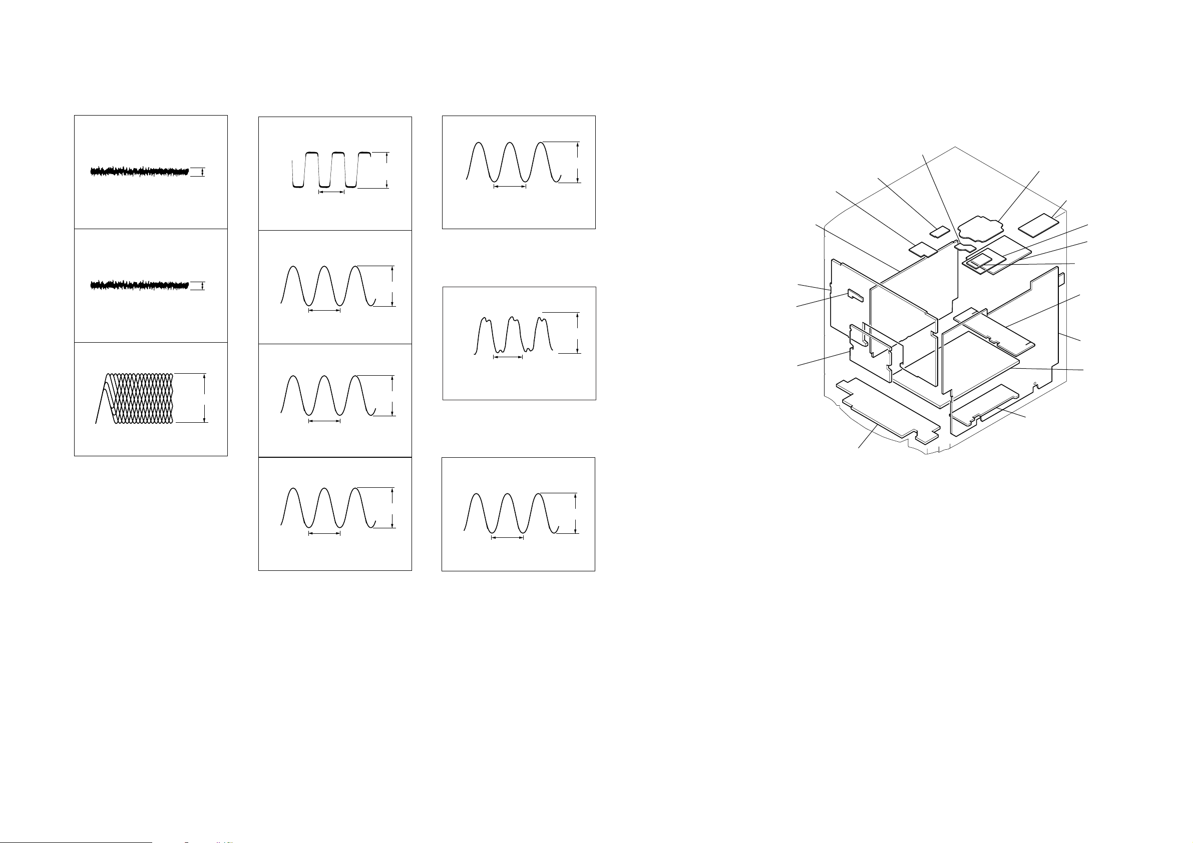
•WAVEFORMS
1
IC101 wa
0.2V/DIV, 0.2 msec/DIV
2
IC101 wd
0.1V/DIV, 1 msec/DIV
3
IC101 ra
TEI
FEI
RFAC
0.15 Vp-p
0.4 Vp-p
– MAIN BOARD –– BD84 BOARD – – SMASTER BOARD –
1
1
IC401 qa
1V/DIV, 10 µsec/DIV
2
IC401 qd
XC-OUT
30.5
X-OUT
2.7 Vp-p
µsec
IC800 2
20.3 nsec
0.5V/DIV, 20 nsec/DIV
– ADC BOARD –
3.3 Vp-p
1
IC03 1
2 µsec
1V/DIV, 1
3
µ
T101 5
sec/DIV
TAPE REC only
81.3 nsec
• CIRCUIT BOARDS LOCATION
0.8 Vp-p
4 Vp-p
0.2V/DIV, 0.5 µsec/DIV
0.9 ± 0.4 Vp-p
10.5 µsec
50V/DIV, 10 µsec/DIV
4
T101 4
50V/DIV, 10
TAPE REC only
10.5 µsec
µ
sec/DIV
67 Vp-p
82 Vp-p
2V/DIV, 50 nsec/DIV
– CDG BOARD –
1
IC1001 tl
69.84 µsec
2V/DIV, 50 nsec/DIV
XI1
5.9 Vp-p
HCD-GNX660
2525
HCD-GNX660
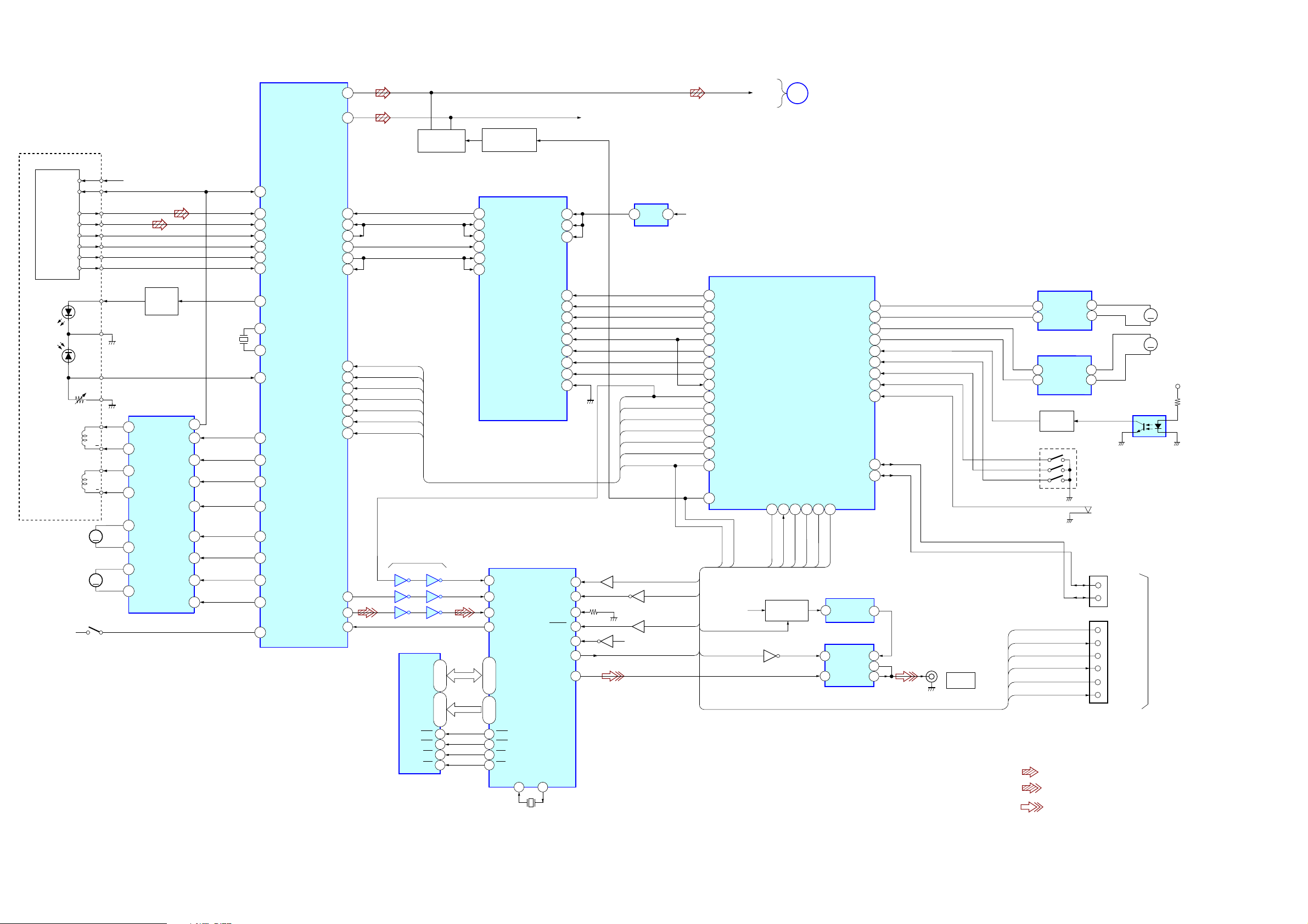
7-1. BLOCK DIAGRAM – CDG SECTION –
OPTICAL PICK-UP
BLOCK
(KSM-215DCP/C2NP)
DETECTOR
VCC
VC
FOCUS
COIL
TRACKING
COIL
(SPINDLE)
M102
(SLED)
S101
(LIMIT)
A
B
C
D
E
F
M101
LD
GND
PD
VR
F
T+
T
M
M
+3.3V
LD
DRIVER
Q10
X171
16.9MHz
IC251
SL/SP MOTOR
DRIVER
F+
12
CH2OUT-F
11
CH2OUT-R
13
CH1OUT-R
14
CH1OUT-F
15
CH4OUT-R
16
CH4OUT-F
17
CH3OUT-F
CH3OUT-R
18
OUT
VREF
CH1FIN
CH1RIN
CH2FIN
CH2RIN
CH3FIN
CH3RIN
OPIN+
MUTE
26
4
5
6
7
23
22
2
20
100
VC
25
26
A
27
B
28
C
29
D
19
E
20
F
36
LD
XTAO
77
78
XTAI
37
PD
11
TFDR
12
TRDR
13
FFDR
14
FRDR
SFDR
9
SRDR
10
6
MDP
XRST
7
SSTP
IC101
RF AMP, DSP, DAC
AOUT1
AOUT2
PCMD1
LRCKI
LRCK
PCMD
BCK
BCK1
XTACN
XRST
DATA
XLAT
CLOCK
SENS
SCOR
WFCK
SBSO
EXCK
81
86
61
62
65
66
60
100
102
104
105
107
115
110
98
99
CD-L
R-CH
CD MUTE
Q237,287
63
95
XTACN
XRST
DATA
XLT
CLOCK
SENS
SCOR
IC1005
5
6
98
1
34
2
13
11 10
12
IC1002
DRAM
DQ1-4
1,2,24,25
A0-7
9-12,14-17
4
RAS
CAS
23
WE
3
CE
22
CD MUTE DRIVE
Q307, 308
11
SDO0
16
LRCKIA
19
SFSY/LRCK1B
14
SDI0
15
BCKIA
18
SBSY/BCK1B
SBSY
4
SFSY
5
DATA
3
2
CLCK
25,27,29,30
15-22
14
RAS
CAS
26
WE
13
CE
28
IC301
MP3 DECODER
PO11/BUCK/AD14
IC1001
VIDEO D/A
VD0-3
VA0-7
XO1
60
VDD
VDD
VDDM
STANBY
MIACK
MICK
MIDIO
MILP
MICS
RESET
SRMSTB
MUTE
PDOWN
SENTSC
RESET
VDOUT
XI1
59
DEN
GDET
IC303
REG
MUTE DATA
HALT_CLK
CDG-RST
CDG-DET
+3.3V
MP3 STB
27
26
MP3 REQ
25
MP3 ACK
7
MP3 CLK
5
MP3 DATA OUT
24
MP3 LP
23
MP3 CS
22
MP3 RST
6
MP3 DATA IN
19
SCOR
21
SENS
CD-CLK
82
XLAT
3
2
CD-DATA
1
XRST
28
XTACN
34
CD MUTE
HALT_CLK
CDG-POWER
VMUTE
MUTE DATA
VCC
IC401 (1/5)
SYSTEM
CONTROL
CDG-POWER
35
33 31 32 12
CDG-POWER
CDG-RST
+B SWITCH
Q1007,1008
Q1010
55
21
40
3
36
8
7
6
5
4
2
41
Q1005,1009
6
56
PAL/_NTSC
55
54
Q1001
52
37
44
5 1
MP3 STB
MP3 REQ
MP3 ACK
MP3 CLK
MP3 DATA
MP3 LP
MP3 CS
MP3 RST
SCOR
SENS
CLOCK
XLT
DATA
XRST
XTACN
Q1004
Q1002,1006
EVER+3.3V
A
VMUTE
CDG RST
VMUTE
MAIN
SECTION
(Page 28)
RESET
CDG-DET
RESET
CDG-DET
TBL_SENS
OPEN SW
IIC-DATA
IIC-CLK
CNVSS
9
CNVSS
IC1003
+5V REG
VIN
1
IC1006
VIDEO BUFFER
PWR
1
SAVE
VIN
4
LM-R
LM-F
TM-R
TM-F
E-1
E-2
E-3
VOUT
VCC
VSAG
VOUT
IC701
TABLE LOADING
MOTOR DRIVER
OUT1
OUT2
OUT1
OUT2
E-3
E-2
E-1
4
2
4
2
ROTARY
ENCODER
S751
(OPEN)
NO401
3
4
CN402
2
3
6
7
8
9
IIC-CLK
IIC-DATA
TXD1
RTS1
CLK1
RXD1
CN VSS
RESET
M
M
(TABLE)
IC731
TBL ADDRESS
SENS
ON BOARD
PROGRAM
M751
(TABLE LOADING)
M741
M+9V
49
48
47
46
42
45
44
43
41
30
29
3
6
3
2
J1001
VIDEO
OUT
RIN
9
FIN
7
TABLE MOTOR DRIVER
RIN
9
FIN
7
INVERTER
Q731
VMUTE
MUTE DATA
CDG-RST
CDG-DET
CNVSS
RESET
IC712
S711
• R-CH is omitted due to same as L-CH.
• SIGNAL PATH
: CD
: CDG
HCD-GNX660
X1002
14.31818MHz
: VIDEO
2626
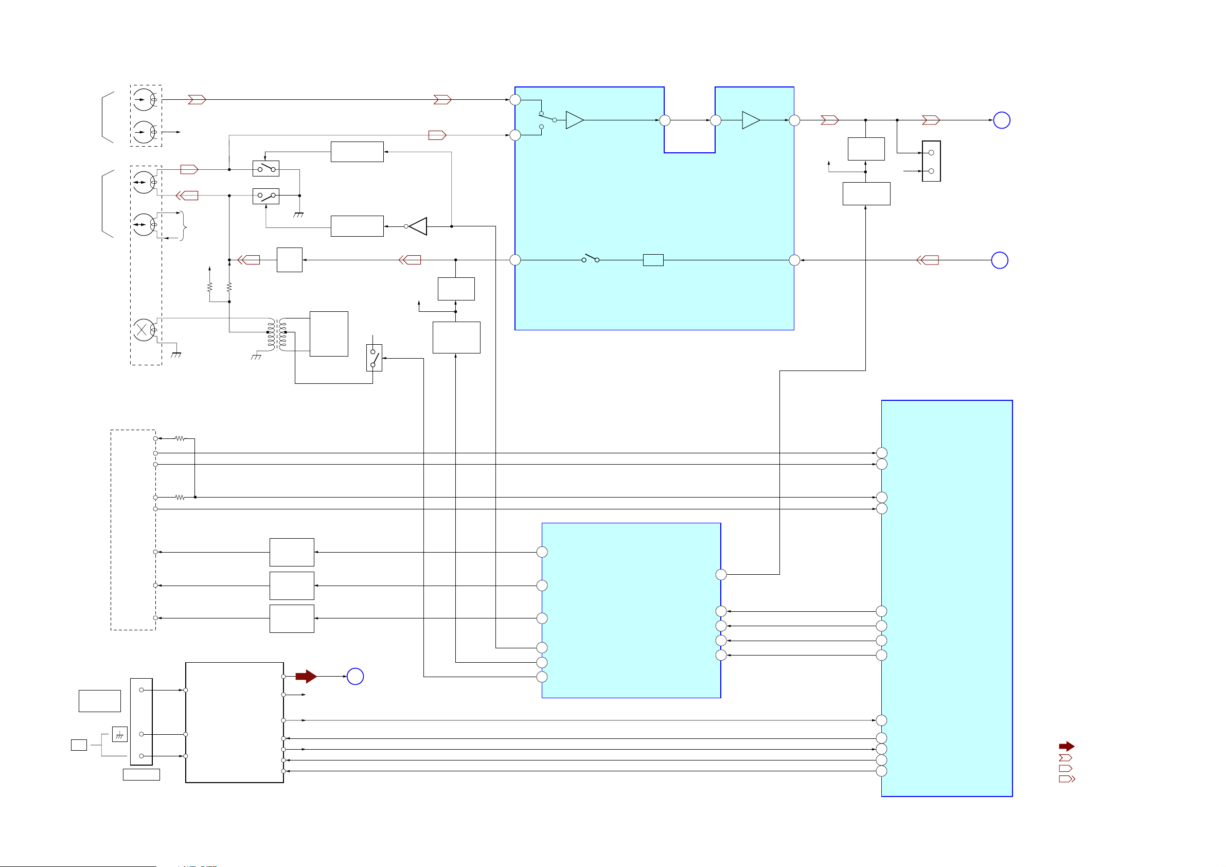
7-2. BLOCK DIAGRAM – TAPE/TUNER SECTION –
DECK-A
L – CH
PB
HEAD
R – CH
DECK-B
L – CH
REC/PB
HEAD
R – CH
ERASE
HEAD
R-CH
R-CH
R-CH
Q166
Q154, 155
C174, L104
BIAS
TRAP
T101
BIAS OSC
SWITCH DRIVE
Q110, 111
SWITCH DRIVE
Q107, 108
Q101
BIAS+9V
Q109
R-CH
MUTE
Q175
TC REC
MUTE DRIVE
Q301, 302
AIN1
75
76
BIN1
REC-OUT1
17
HCD-GNX660
Ver. 1.2
A
B
EQ OUT1
78
IC101(1/2)
DECK A/B SELECT,
PB/REC EQUALIZER AMP
EQ
1
L
R
3
REC-OUT-L
TC-PB-L
TEST
CONNECTOR
C
D
MAIN
SECTION
(Page 28)
MAIN
SECTION
(Page
28
)
TAI1
79
PB OUT1
REC IN1
80
MUTE
R-CH
15
Q103
R-CH
MUTE DRIVE
Q303, 304
CN111
AM
FM 75
COAXIAL
TAPE
MECHANISM
DECK
REC(FWD)
B SHUT
A SHUT
BHALF
AHALF
ATRGM+
BTRGM+
CAP M+
CN101
ANTENNA
FM/AM TUNER UNIT
FM ANT
AM ANT
AM ANT
ST-L
ST-R
TUNED
ST-DIN
ST-DOUT
ST-CLK
ST-CE
A TRIG
DRIVE
Q122, 123
B TRIG
DRIVE
Q118, 119
CAP MOTOR
DRIVE
Q120, 121
R-CH
ST-L
E
Q113,114
MAIN
SECTION
(Page
IC401(2/5)
SYSTEM CONTROL
(CD/TAPE MECHANISM CONTROL)
90
B SHUT
A SHUT
89
B-HALF
91
A-HALF
63
17
A-TRIG
TC-MUTE
19
B-TRIG
IC403(1/2)
SIGNAL IN/OUT CONTROL
CAPM-CNT
18
21
TC-RELAY
7
REC-MUTE
20
REC BIAS
28
)
LATCH
CLK
RESET
DI1
5
4
3
2
26
70 IO-EXP-LAT
69 IO-EXP-CLK
68 IO-EXP-RST
66 IO-EXP-DATA-OUT
TUNED
40
39
ST-DIN
37
ST-DOUT
38
ST-CLK
ST-CE
36
• R-CH is omitted due to same as L-CH.
• SIGNAL PATH
: TUNER (FM/AM)
: PLAYBACK (DECK A)
: PLAYBACK (DECK B)
: RECORD
HCD-GNX660
2727
 Loading...