

Sony HCD-GNV99D, HCD-GNV111D Service Manual
HCD-GNV99D/
GNV111D
SERVICE MANUAL
Ver.1.0 2005.04
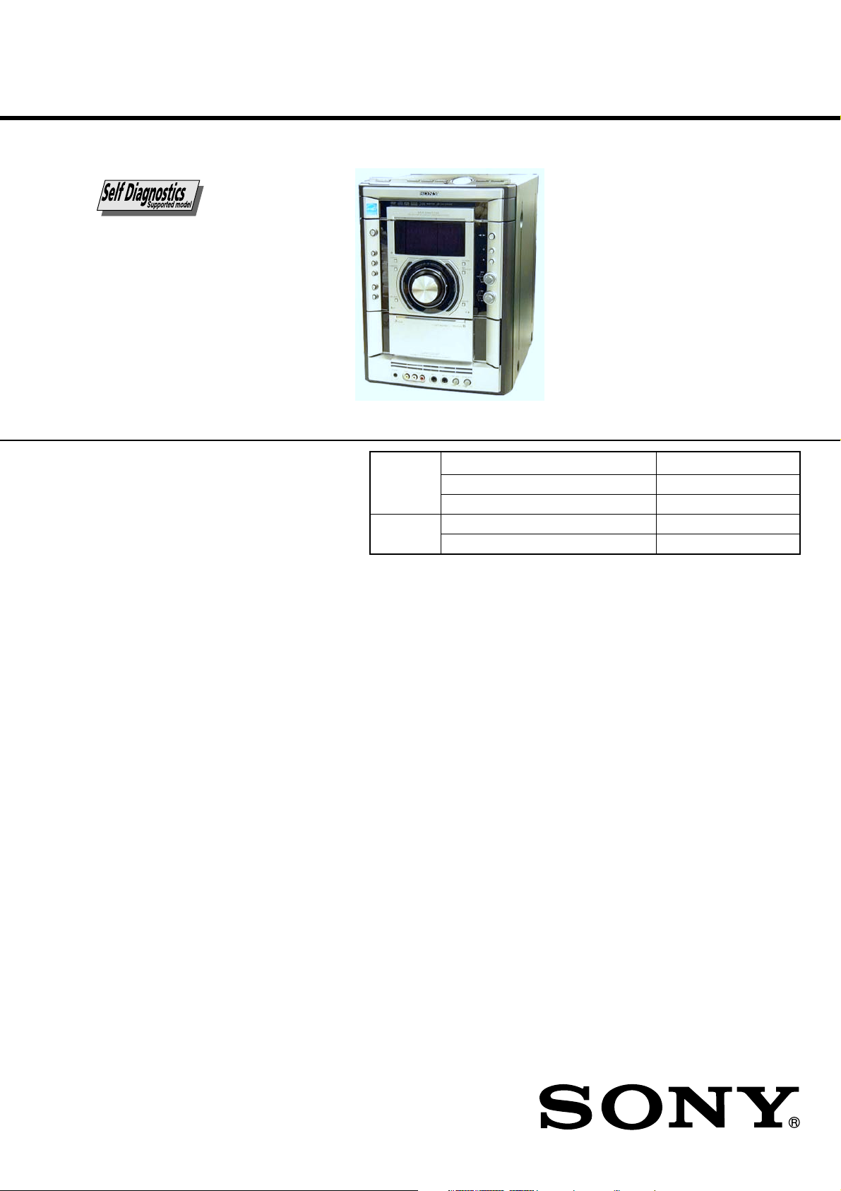
• HCD-GNV99D/GNV111D are the Amplifier,
DVD player, tape deck and tuner
section in MHC-GNV99D/GNV111D.
Photo : HCD-GNV111D
DVD
Section
TAPE Model Name Using Similar Mechanism NEW
Section Tape Transport Mechanism Type CMAT2E2
Model Name Using Similar Mechanism NEW
DVD Mechanism Type CDM74H-DVBU101
Optical Pick-up Name KHM-310CAB/C2NP
E Model
HCD-GNV99D/GNV111D
Australian Model
HCD-GNV111D
Amplifier section
MHC-GNV111D
The following are measured at AC 120, 127, 220, 240V 50/60 Hz
DIN power output (rated)
Front speaker: 110 W + 110 W
(6 ohms at 1 kHz, DIN)
Center speaker: 50 W
(16 ohms at 1 kHz, DIN)
Surround speaker: 110 W + 110 W
(6 ohms at 1 kHz, DIN)
Continuous RMS power output (reference)
Front speaker: 160 W + 160 W
(6 ohms at 1 kHz, 10% THD)
Center speaker: 80 W
(16 ohms at 1 kHz, 10% THD)
Surround speaker: 160 W + 160 W
(6 ohms at 1 kHz, 10% THD)
MHC-GNV99D
The following are measured at AC 120, 127, 220, 240V 50/60 Hz
DIN power output (rated)
Front speaker: 130 W + 130 W
(6 ohms at 1 kHz, DIN)
Center speaker: 30 W
(8 ohms at 1 kHz, DIN)
Surround speaker: 30 W + 30 W
(8 ohms at 1 kHz, DIN)
Continuous RMS power output (reference)
Front speaker: 180 W + 180 W
(6 ohms at 1 kHz, 10% THD)
Center speaker: 50 W
(8 ohms at 1 kHz, 10% THD)
Surround speaker: 50 W + 50 W
(8 ohms at 1 kHz, 10% THD)
SPECIFICATIONS
Inputs
VIDEO INPUT: VIDEO: 1 Vp-p, 75 ohms
(phono jacks) AUDIO L/R: Voltage
250 mV, impedance 47 kilohms
TV/SAT AUDIO IN L/R: voltage 250 mV/450 mV,
(phono jacks) impedance 47 kilohms
MIC 1/2: sensitivity 1 mV,
(phone jack) impedance 10 kilohms
Outputs
AUDIO OUT: Voltage 250 mV
(phono jacks) impedance 1 kilohm
VIDEO OUT: max. output level 1 Vp-p,
(phono jack) unbalanced, Sync.
negative load impedance 75 ohms
COMPONENT VIDEO
OUT: Y: 1 Vp-p, 75 ohms
PB/CB: 0.7 Vp-p, 75 ohms
PR/CR: 0.7 Vp-p, 75 ohms
S VIDEO OUT: Y: 1 Vp-p, unbalanced,
(4-pin/mini-DIN jack) Sync. negative
C: 0.286 Vp-p load impedance 75 ohms
PHONES: accepts headphones of
(stereo mini jack) 8 ohms or more
FRONT SPEAKER: Use only the supplied speakers
SURR SPEAKER: Use only the supplied speakers
CENTER SPEAKER: Use only the supplied speaker
SUBWOOFER OUT: Voltage 250 mV
(phono jack) impedance 1 kilohm
– Continued on next page –
MINI Hi-Fi COMPONENT SYSTEM
9-879-585-01
2005D0279-1
© 2005.04
Sony Corporation
Audio Group
Published by Sony Engineering Corporation

HCD-GNV99D/GNV111D
Disc player section
System Compact disc and digital audio and video
system
Laser Semiconductor laser
(DVD: λ = 650 nm, CD: λ = 790 nm)
Emission duration: continuous
Frequency response DVD (PCM 48 kHz):
2 Hz – 22 kHz (±1dB)
CD: 2 Hz – 20 kHz (±0.5 dB)
Video color system format
NTSC and PAL
Tape deck section
Recording system 4-track 2-channel stereo
Frequency response 50 – 13,000 Hz (±3 dB), using Sony TYPE I
tape
Tuner section
FM stereo, FM/AM superheterodyne tuner
FM tuner section
Tuning range 87.5 – 108.0 MHz (50 kHz step)
Antenna FM lead antenna
Antenna terminals 75 ohms unbalanced
Intermediate frequency 10.7 MHz
AM tuner section
Tuning range
Saudi Arabian model: 531– 1,602 kHz
(with the interval set at 9 kHz)
Other models: 531 – 1,602 kHz
(with the interval set at 9 kHz)
530 – 1,710 kHz
(with the interval set at 10 kHz)
Antenna AM loop antenna
Antenna terminals External antenna terminal
Intermediate frequency 450 kHz
Notes on chip component replacement
• Never reuse a disconnected chip component.
• Notice that the minus side of a tantalum capacitor may be
damaged by heat.
Flexible Circuit Board Repairing
• Keep the temperature of soldering iron around 270˚C
during repairing.
• Do not touch the soldering iron on the same conductor of the
circuit board (within 3 times).
• Be careful not to apply force on the conductor when soldering
or unsoldering.
CAUTION
Use of controls or adjustments or performance of procedures
other than those specified herein may result in hazardous
radiation exposure.
This appliance is classified as
a CLASS 1 LASER product.
This label is located on the rear
exterior.
General
Power requirements
Australian model: 230 – 240 V AC, 50/60 Hz
Saudi Arabian model: 120 – 127 V, 220 V or
230 – 240 V AC, 50/60 Hz
Adjustable with voltage selector
Other models: 120 V, 220 V or
230 – 240 V AC, 50/60 Hz
Adjustable with voltage selector
Power consumption
MHC-GNV111D 380 W
MHC-GNV99D 285 W
Dimensions (w/h/d) (Approx.)
HCD-GNV111D 280 × 371 × 398.5 mm
HCD-GNV99D 280 × 360 × 398.5 mm
Mass (Approx.)
HCD-GNV111D 16.1 kg
HCD-GNV99D 15.2 kg
Design and specifications are subject to change without notice.
SAFETY-RELATED COMPONENT WARNING!!
COMPONENTS IDENTIFIED BY MARK 0 OR DOTTED LINE WITH
MARK 0 ON THE SCHEMATIC DIAGRAMS AND IN THE PARTS
LIST ARE CRITICAL TO SAFE OPERATION. REPLACE THESE
COMPONENTS WITH SONY PARTS WHOSE PART NUMBERS
APPEAR AS SHOWN IN THIS MANUAL OR IN SUPPLEMENTS
PUBLISHED BY SONY.
2

TABLE OF CONTENTS
HCD-GNV99D/GNV111D
1. SERVICING NOTES ................................................ 4
2. GENERAL ................................................................... 6
3. DISASSEMBLY
3-1. Disassembly Flow ........................................................... 8
3-2. Case ................................................................................. 9
3-3. Loading Panel Assy ......................................................... 9
3-4. Front Panel Assy.............................................................. 10
3-5. Tuner Pack ....................................................................... 11
3-6. Tape Mechanism Deck, MIC Board ................................ 12
3-7. Panel Board, CD-SW Board ............................................ 13
3-8. DVD Mechanism Deck ................................................... 14
3-9. Video Board, DMB10 Board........................................... 15
3-10. Back Panel ....................................................................... 16
3-11. Primary Board ................................................................. 16
3-12. Power Amp PC Board Assy, Main Board ........................ 17
3-13. DVD SURR Board, PA Board......................................... 17
3-14. Power Transformer (T1200) ............................................ 18
3-15. Driver Board, SW Board ................................................. 18
3-16. DVD Assy ........................................................................ 19
3-17. Optical Pick-up ................................................................ 19
3-18. Sensor Board ................................................................... 20
3-19. Motor (TB) Board ........................................................... 20
3-20. Motor (LD) Board ........................................................... 21
4. TEST MODE ............................................................... 22
5. MECHANICAL ADJUSTMENTS......................... 27
6. ELECTRICAL ADJUSTMENTS .......................... 27
7. DIAGRAMS .......................................................... 29
7-1. Block Diagram – RF Section –....................................... 30
7-2. Block Diagram – Video Section – ................................... 31
7-3. Block Diagram – Tape/Tuner Section – .......................... 32
7-4. Block Diagram – Main Section – .................................... 33
7-5. Block Diagram – AMP Section – .................................... 34
7-6. Block Diagram – Display/Power Section –..................... 35
7-7. Printed Wiring Board – DMB10 Board (Side A) – ......... 36
7-8. Printed Wiring Board – DMB10 Board (Side B) – ........ 37
7-9. Schematic Diagram – DMB10 Board (1/4) – ................ 38
7-10. Schematic Diagram – DMB10 Board (2/4) – ................ 39
7-11. Schematic Diagram – DMB10 Board (3/4) – ................ 40
7-12. Schematic Diagram – DMB10 Board (4/4) – ................ 41
7-13. Printed Wiring Boards – CD Mechanism Boards – ....... 42
7-14. Schematic Diagram – CD Mechanism Boards – ........... 43
7-15. Printed Wiring Board – Main Board – ............................ 44
7-16. Schematic Diagram – Main Board (1/5) – ..................... 45
7-17. Schematic Diagram – Main Board (2/5) – ..................... 46
7-18. Schematic Diagram – Main Board (3/5) – ..................... 47
7-19. Schematic Diagram – Main Board (4/5) – ..................... 48
7-20. Schematic Diagram – Main Board (5/5) – ..................... 49
7-21. Printed Wiring Board – Panel Board – ............................ 50
7-22. Schematic Diagram – Panel Board – .............................. 51
7-23. Printed Wiring Boards – CD-SW, JOG
And MIC Boards – .......................................................... 52
7-24. Schematic Diagram – CD-SW, JOG
And MIC Boards – .......................................................... 53
7-25. Printed Wiring Board – PA Board – ................................ 54
7-26. Schematic Diagram – PA Board – .................................. 55
7-27. Printed Wiring Board – DVD SURR Board – ................. 56
7-28. Schematic Diagram – DVD SURR Board – ................... 57
7-29. Printed Wiring Board – Video Board – ........................... 58
7-30. Schematic Diagram – Video Board – ............................. 59
7-31. Printed Wiring Boards – Trans And Primary Boards – ... 60
7-32. Schematic Diagram – Trans And Primary Boards –....... 61
8. EXPLODED VIEWS
8-1. Case, Rear Panel Section ................................................. 73
8-2. Front Panel Section ......................................................... 74
8-3. Chassis Section ................................................................ 75
8-4. DVD Mechanism Section-1 (CDM74H-DVBU101) ...... 76
8-5. DVD Mechanism Section-2 (CDMm74H-DVBU101) ... 77
9. ELECTRICAL PARTS LIST ....................... 78
3
HCD-GNV99D/GNV111D
SECTION 1
SERVICING NOTES
NOTES ON HANDLING THE OPTICAL PICK-UP BLOCK
OR BASE UNIT
The laser diode in the optical pick-up block may suffer electrostatic
break-down because of the potential difference generated by the
charged electrostatic load, etc. on clothing and the human body.
During repair, pay attention to electrostatic break-down and also
use the procedure in the printed matter which is included in the
repair parts.
The flexible board is easily damaged and should be handled with
care.
NOTES ON LASER DIODE EMISSION CHECK
The laser beam on this model is concentrated so as to be focused on
the disc reflective surface by the objective lens in the optical pickup block. Therefore, when checking the laser diode emission,
observe from more than 30 cm away from the objective lens.
LASER DIODE AND FOCUS SEARCH OPERATION
CHECK
Carry out the “S curve check” in “CD section adjustment” and check
that the S curve waveform is output several times.
NOTE ON REPLACEMENT OF DMB10 BOARD
New part of EEPROM (IC103) on the DMB10 board can not be
used. Therefore, if the mounted DMB10 board (A-1099-272-A or
A-1099-344-A or A-1115-347-A) is replaced, exchange new
EEPROM with that used before the replacement.
UNLEADED SOLDER
Boards requiring use of unleaded solder are printed with the leadfree mark (LF) indicating the solder contains no lead.
(Caution: Some printed circuit boards may not come printed with
the lead free mark due to their particular size)
: LEAD FREE MARK
Unleaded solder has the following characteristics.
• Unleaded solder melts at a temperature about 40 °C higher
than ordinary solder.
Ordinary soldering irons can be used but the iron tip has to be
applied to the solder joint for a slightly longer time.
Soldering irons using a temperature regulator should be set to
about 350 °C.
Caution: The printed pattern (copper foil) may peel away if
the heated tip is applied for too long, so be careful!
• Strong viscosity
Unleaded solder is more viscou-s (sticky, less prone to flow)
than ordinary solder so use caution not to let solder bridges
occur such as on IC pins, etc.
• Usable with ordinary solder
It is best to use only unleaded solder but unleaded solder may
also be added to ordinary solder.
Self-diagnosis Function
(When letters/numbers appear in the
display)
When the self-diagnosis function is activated to
prevent the system from malfunctioning, a 5character service number (e.g., C 13 50) with a
combination of a letter and 4 digits appears in
the on-screen display and the front panel
display. In this case, check the following table.
First 3
characters of
the service
number
C 13 The disc is dirty.
C 31 The disc is not inserted correctly.
E XX
(xx is a number)
Cause and/or corrective action
•Clean the disc with a soft cloth
(page xx).
•Restart the system, then re- insert
the disc correctly.
To prevent a malfunction, the
system has performed the selfdiagnosis function.
•Contact your nearest Sony
dealer or local authorized Sony
service facility and give the 5character service number.
Example: E 61 10
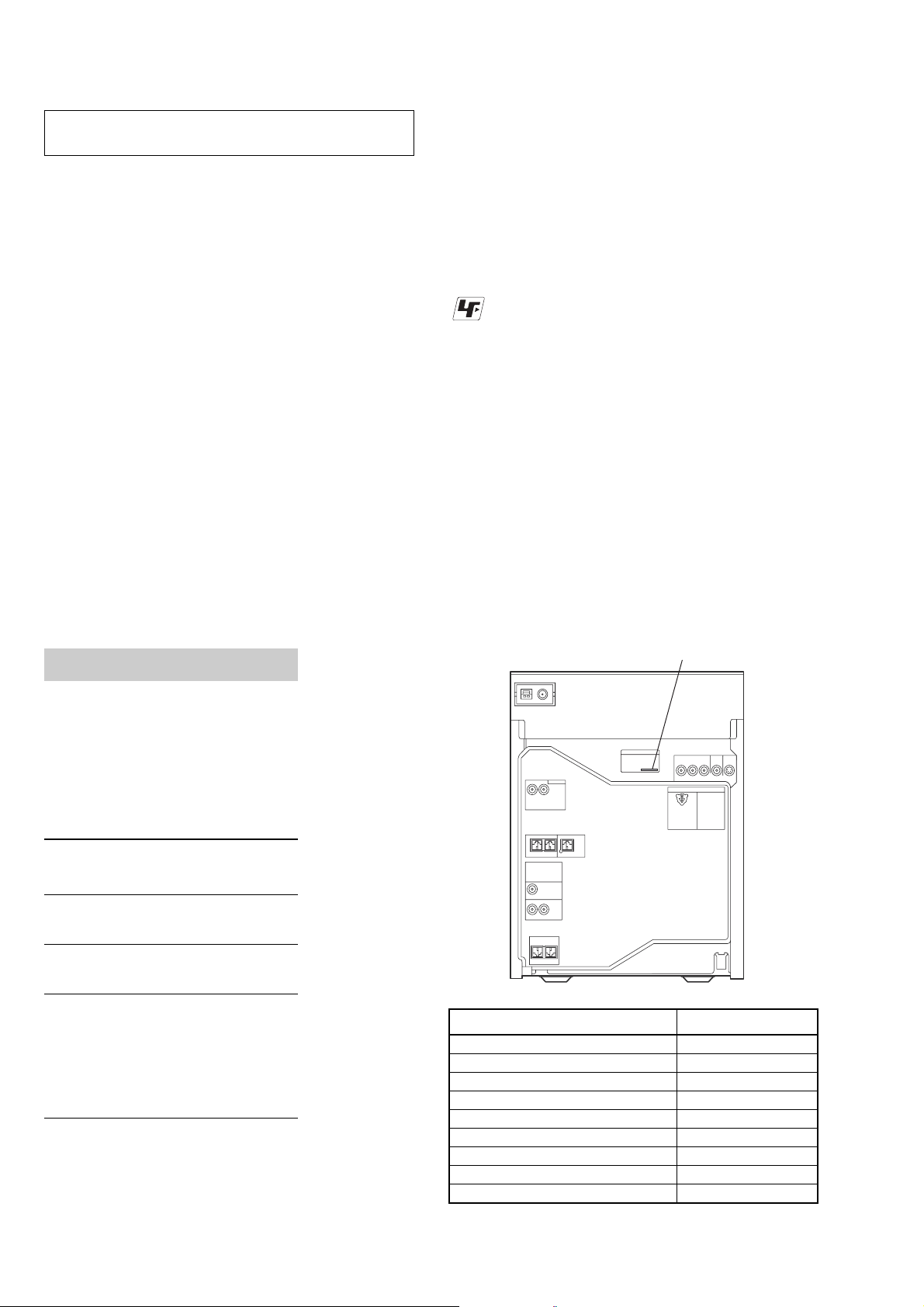
• MODEL IDENTIFICATION
– Back Panel –
PAR T No.
MODEL PART No.
GNV99D : E3, E15 models 2-584-723-0[]
GNV111D : E2 model 2-584-724-0[]
GNV99D : EA model 2-596-940-0[]
GNV99D : PH model 2-596-941-0[]
GNV111D : MY, SP models 2-596-943-0[]
GNV111D : EA model 2-596-944-0[]
GNV111D : E3, E15 models 2-596-945-0[]
GNV111D : AUS model 2-596-946-0[]
GNV111D : PH model 2-596-947-0[]
4

d
• Service Position-1 (DMB10 Board)
CN302
HCD-GNV99D/GNV111D
J-2501-102-A
(1mm/13p/L300)
CN520
CN521
CN106
DMB10 board
• Service Position-2 (PA and DVD SURR Boards)
MAIN boar
J-2501-086-A
(1mm/19p/L300)
DVD mechanism deck
front panel assy
J-2501-167-A
(1.25mm/17p/L300)
J-2501-077-A
(1.25mm/13p/L300)
CN508
CN509
MAIN board
PANEL board
TCM block
back panel
PA board
DVD SURR board
5

HCD-GNV99D/GNV111D
657
Illustrati
LOCATING THE CONTROLS
List of button locations and reference pages
SECTION 2
GENERAL
This section is extracted
from instruction manual.
How to use page 106 to 108
Use this page to find the location of buttons and other
parts of the unit and remote that are mentioned in the
text.
Unit
ALPHABETICAL ORDER
A – D
AMP MENU ef
AUTO/MANUAL
CD SYNC qd
Deck A es
Deck B ws
DIRECTION qk
DISC 1 ~ 3 7
Disc tray 9
DISPLAY rf
Display rg
DVD r;
E – L
ECHO LEVEL wf
ENTER wa
EQ BAND qa
EX-CHANGE/DISC SKIP 6
GROOVE ej
ILLUMINATION rd
IR Receptor ra
*
2
SYMBOLS
?/1 (power) rs
Z OPEN/CLOSE 5
nN (play) qs
.> (go backward/forward)
mM (rewind/fast forward)
X (pause) qf
x (stop) qg
Z A (Eject A) ed
B Z (Eject B) w;
*MHC-GNV111D only
Top Panel
on number
r
TAPE A/B ek (63–65, 75, 78, 79)
Name of button/part Reference page
SLOW ql
RR
qj
ql
23
1
4
M – R
MASTER VOLUME 8
MIC 1 (jack) wj
MIC 2 (jack) wh
MIC LEVEL wg
OPERATION DIAL e;
PHONES (jack) wl
Power illuminator wd
PRESET +/– qj
PROGRESSIVE q;
REC PAUSE/START qh
S – Z
SOUND FIELD rh
SOUND FLASH ea
SPEAKERS
TAPE A/B ek
Tape lid ws es
TUNER/BAND el
TUNING +/– ql
TV/SAT eh
VIDEO INPUT (jacks) wk
VIDEO eg
X-ROUND buttons
X-ROUND JOG
X-ROUND OFF
*
1
*
*
*
3
4
1
WAVE/FADER/BALANCE/
RANDOM/TWISTER
Front Panel
rh
rg
rf
rd
rs
ra
r;
el
ek
ej
eh
eg
ef
ed
es
ea
e;
8
0
qs
qf
qh
qk
w;
ws
9
qa
qd
qg
qj
ql
wz
wd
6
wk wgwhwj X
wl

Remote control
HCD-GNV99D/GNV111D
This section is extracted
from instruction manual.
ALPHABETICAL ORDER
A – L
ADVANCE wd
ALBUM +/– qa
ANGLE q;
AUDIO 8
CLEAR wj
DISC SKIP 3
DISPLAY es
ENTER wg
FM MODE 7
FUNCTION +/– 4
KARAOKE MODE e;
KARAOKE PON wl
KEY CONTROL #/2 ea
M – S
MENU qs
Numeric Buttons
PICTURE NAVI 6
PRESET + qg
PRESET – ws
REPEAT 7
REPLAY wd
SLEEP ef
SLOW qh
SLOW wa
SOUND FIELD 5
STEP C wd
SUBTITLE 9
T – Z
THEATRE SYNC 1
TIMER MENU eg
TIME/TEXT ed
TOP MENU wh
TUNING + qh
TUNING – wa
2)
ql
TV
TV CH +
TV CH –
TV/VIDEO
TV VOL +/–
TV &/1
VOLUME +/–
2)
qg
2)
ws
2)
ef
1)2)
2)
2
1)2)
wk
qd
1)
qd
NUMBERS AND SYMBOLS
?/1 (power) 2
x (stop) qj
X (pause) qk
1)
(play) w;
H
> (go forward) qg
. (go backward) ws
M (fast forward) qh
m (rewind) wa
M/m/</, wg
2)
wk
10/0
2)
-/--
wj
O RETURN wf
DISPLAY qf
c STEP wd
1)
The numeric button 5, TV VOL +, VOLUME + and
H buttons have a tactile dot. Use the tactile dot as
a reference when operating the system.
2)
This button is used to operate a Sony TV. For
details, see “Operating a Sony TV” on page 12.
ef
es
e;
wk
wh
wf
ws
w;
eg
ed
ea
wl
wj
wg
wd
wa
ql
1
3
5
7
9
qa
qd
qg
qj
2
4
6
8
q;
qs
qf
qh
qk
Setting the clock
1
Press ?/1 to turn on the system.
2
Press TIMER MENU.
The hour indication flashes in the display.
3
Press M or m repeatedly to set the hour.
4
Press ENTER.
The minute indication flashes in the
display.
5
Press M or m repeatedly to set the
minute.
6
Press ENTER.
The clock starts functioning.
To adjust the clock
1
Press TIMER MENU.
“PLAY SET?” flashes in the display.
2
Press M or m repeatedly to select “CLOCK
SET?”, then press ENTER.
The hour indication flashes in the display.
3
Do the same procedures as step 3 to 6
above.
Notes
The clock settings are canceled when you disconnect
the power cord or if a power failure occurs.
You cannot set the clock in power saving mode
.
7
HCD-GNV99D/GNV111D
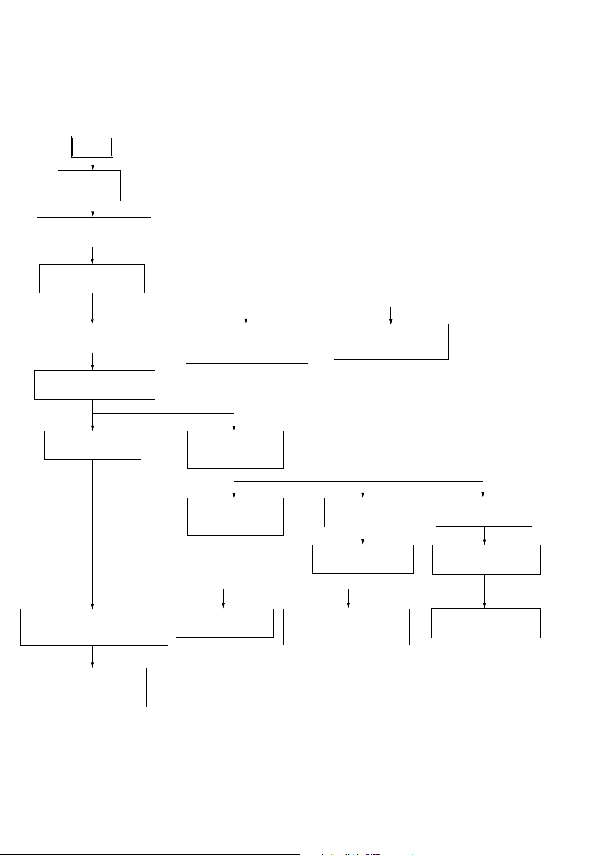
Note:
• The illustration depicts HCD-GNV111D.
• This set can be disassembled in the order shown below.
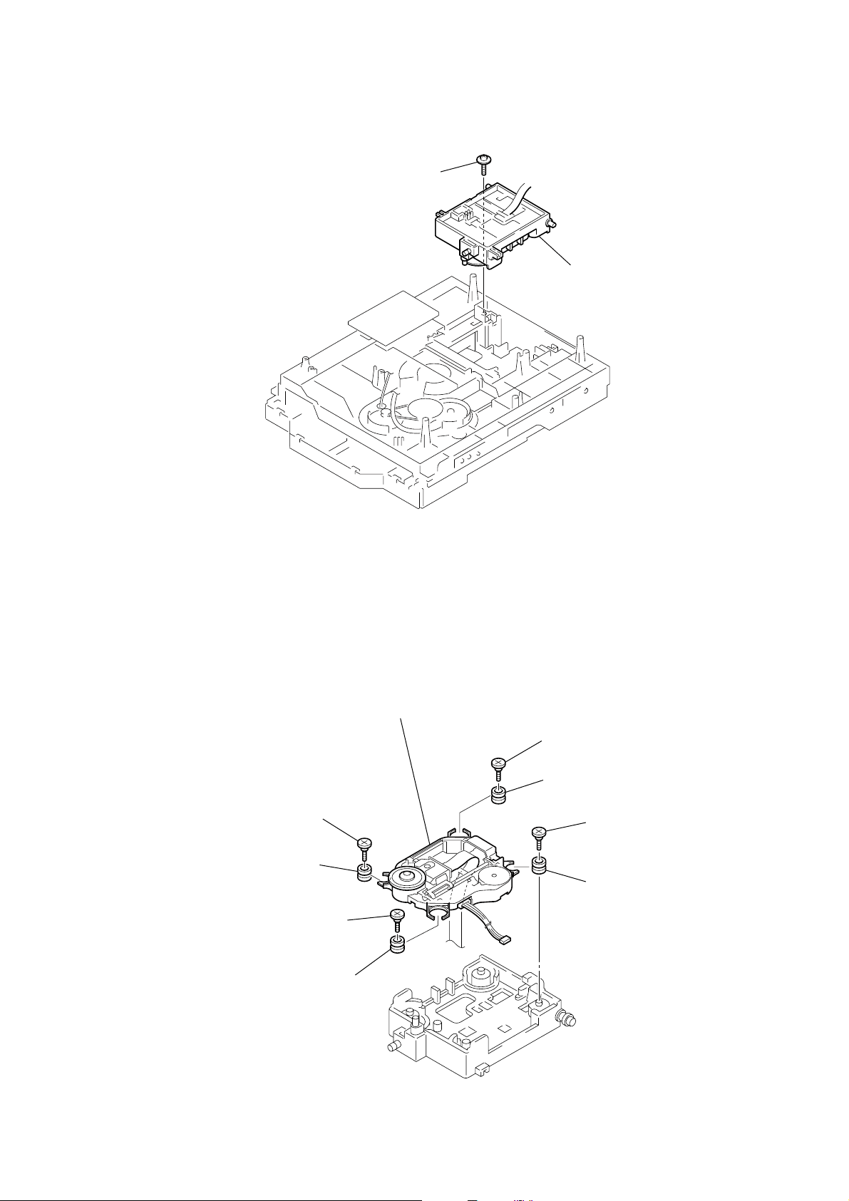
3-1. DISASSEMBLY FLOW
SET
3-2. CASE
(Page9)
SECTION 3
DISASSEMBLY
3-3. LOADING PANEL ASSY
(Page9)
3-4. FRONT PANEL ASSY
(Page10)
3-5. TUNER PACK
(Page11)
3-8. DVD MECHANISM DECK
(Page14)
3-10. BACK PANEL
(Page16)
3-6. TAPE MECHANISM DECK,
MIC BOARD
3-9. VIDEO BOARD,
DMB10 BOARD
3-15. DRIVER BOARD,
(P
age12)
(Page15)
SW BOARD
(Page18)
3-7.PANEL BOARD,
CD-SW BOARD
(Page13)
3-16. DVD ASSY
(Page19)
3-18. SENSOR BOARD
(Page20)
3-12. POWER AMP PC BOARD ASSY,
MAIN BOARD
3-13. DVD SURR BOARD,
PA BOARD
(P
(P
age17)
age17)
8
3-11. PRIMARY BOARD
(Page16)
3-17. OPTICAL PICK-UP
(Page19)
3-14. POWER TRANSFORMER
(T1200)
(Page18)
3-19. MOTOR (TB) BOARD
(Page20)
3-20. MOTOR (LD) BOARD
(Page21)

)
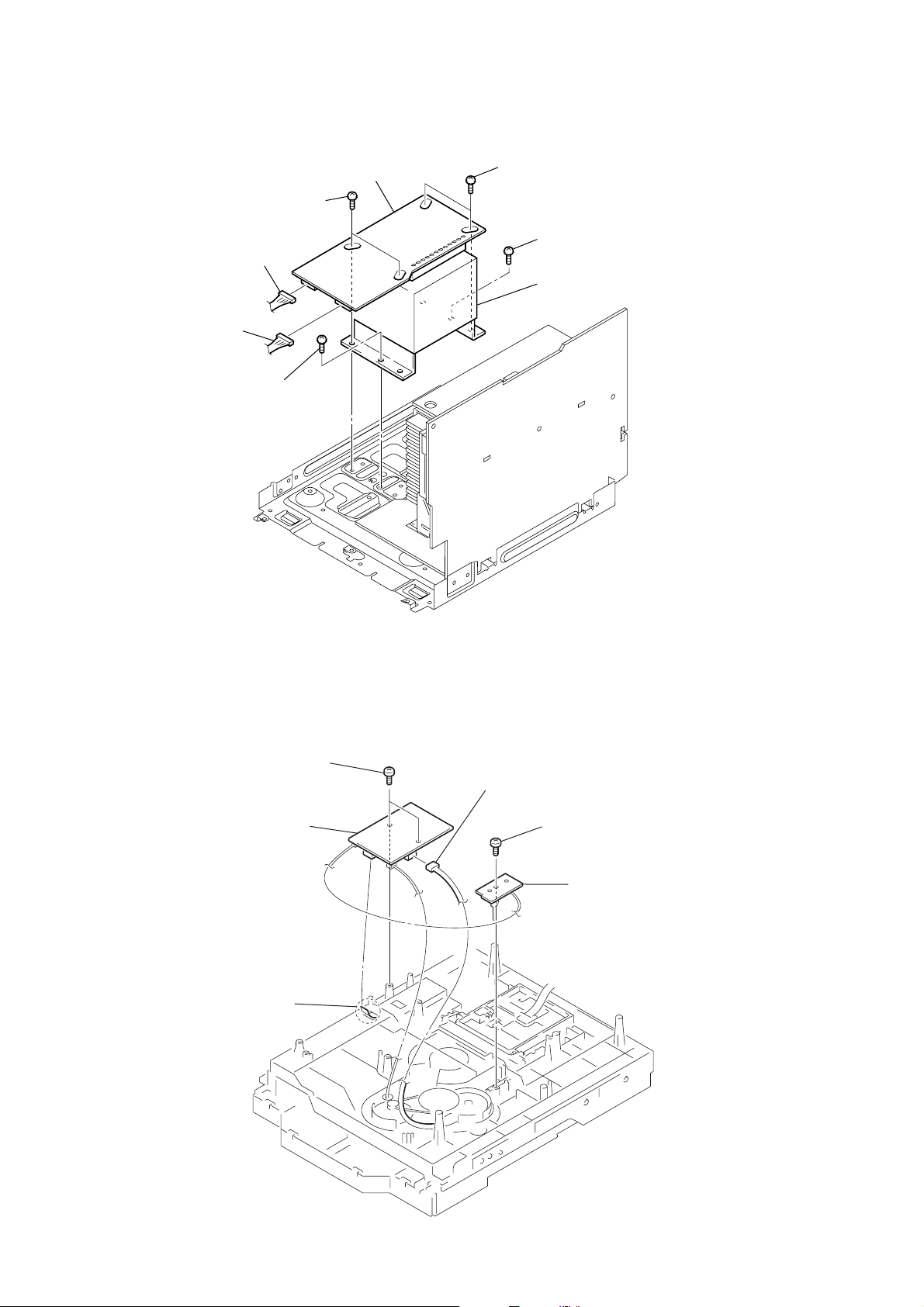
3-2. CASE
4
screw
(case 3 TP2)
(3
3
two screws
(case 3 TP2)
(3
´
8)
HCD-GNV99D/GNV111D
5
three screws
(+BVTP 3
CASE
7
´
12)
6
´
10)
2
screw
(case 3 TP2)
(3
´
12)
6
four screws
(+BVTP 3
´
10
3-3. LOADING PANEL ASSY
DVD mechanismdeck (CDM74H-DVBU101)
1
Turn the pulley to the arrow direction.
Pulley
1
two screws
(case 3 TP2)
´
8)
(3
loading panel assy
4
Front side
2
Pull out disc tray
3
9

HCD-GNV99D/GNV111D
3-4. FRONT PANEL ASSY
4
screw
(+BVTP 3
´
10)
qa
flat wire
(CN509)
0
flat wire
(CN508)
3
screw
(+BVTP 3
qs
connector
(CN100)
´
10)
qd
(CN802)
lug
connector
6
front panel assy
2
two screws
(+BVTP 3
7
connector
(CN1102)
5
screw
(+BVTP 3
8
connector
9
connector
(CN503)
´
10)
1
two screws
(+BVTP 3
´
10)
(CN504)
´
6)
10

)
3-5. TUNER PACK
2
flat wire
3
tuner pack
HCD-GNV99D/GNV111D
1
two screws
(+BVTP 3
4
cover (tuner)
´
6
11

HCD-GNV99D/GNV111D
)
3-6. TAPE MECHANISM DECK, MIC BOARD
4
5
tape mechanism deck
screw
(+BVTP2.6 (3CR))
3
cover (TCM)
1
two screws
(+BVTP2.6 (3CR)
2
two screws
(+BVTP2.6 (3CR))
8
knob (MIC)
6
two screws
(+BVTP2.6 (3CR))
7
bracket (MIC)
9
MIC board
12

3-7. PANEL BOARD, CD-SW BOARD
qh
escutheon (X-ROUND)
qj
CD-SW board
qg
screw
(+BVTP2.6 (3CR))
qf
two screws
(+BVTP2.6 (3CR))
qs
two screws
(+BVTP2.6 (3CR))
0
knob (JOG-X)
qa
screw
(+BVTP2.6 (3CR))
6
three screws
(+BVTP2.6 (3CR))
HCD-GNV99D/GNV111D
5
two screws
(+BVTP2.6 (3CR))
4
four screws
(+BVTP2.6 (3CR))
8
claw
1
knob vol
2
two knobs (AMS)
7
connector
qd
two screws
(+BVTP2.6 (3CR))
(CN902)
3
three screws
(+BVTP2.6 (3CR))
9
PANEL board
13

HCD-GNV99D/GNV111D
)
3-8. DVD MECHANISM DECK
4
DVD mechanism deck
9
connector
(CN800)
8
connector
(CN401)
7
13p(CN520)
flat wire
5
connector
(CN701)
6
flat wire
19p(CN521)
3
three screws
(+BVTP 3
1
three screws
(+BVTP 3
´
10)
2
(+BVTP 3
´
10)
screw
´
10
MAIN board
14

)
3-9. VIDEO BOARD, DMB10 BOARD
6
CDM cover
HCD-GNV99D/GNV111D
3
VIDEO board
2
screw
(+BVTP 3´10)
1
13p(CN801)
5
screw
(+BVTP 3´10)
flat wire
0
two screws
(+BVTP 3´10)
8
flat wire
24p(CN101)
4
two screws
(+BVTP 3´10)
qs
bracket (mediatec
qa
DMB10 board
9
two screws
(+BVTP 3´10)
7
connector
(CN201)
15

HCD-GNV99D/GNV111D
)
3-10. BACK PANEL
2
connector
(CN1204)
9
connector
(CN580)
8
back panel
1
connector
(CN1200)
7
screw
(+BVTP 3
6
screw
(+BVTP 3
5
two screws
(+BVTP 3
4
screw
(+BVTP 3
3
three screws
(+BVTP 3
´
10)
´
10)
´
10)
´
10
´
10)
3-11. PRIMARY BOARD
4
PRIMARY board
1
connector
3
screw
(+BVTP 3´8)
2
connector
16

HCD-GNV99D/GNV111D
s
3-12. POWER AMP PC BOARD ASSY, MAIN BOARD
4
3
screw
(+BVTP 3
1
connector
(CN1213)
2
connector
(CN1212)
two screws
(+BVTP 3
´
6)
´
6)
5
screw
(+BVTP 3
7
6
screw
(+BVTP 3
´
6)
power AMP PC board assy
´
10)
3-13. DVD SURR BOARD, PA BOARD
3
DVD SURR board
0
heat sink
5
two screws
(+BVTP 3
6
´
10)
holder
q;
MAIN board
2
screw
(+BVTP 3
qs
bracket
8
two screws
(+BVTP 3
´
10)
qa
screw
(+BVTP 3
9
(+BVTP 3
´
10)
1
two screw
(transistor)
´
10)
screw
´
10)
qd
PA board
4
connector
(CN602)
9
two screws
(+BVTP 3
7
three screws
(+BVTP 3
´
10)
8
two screws
(transistor)
´
10)
17
HCD-GNV99D/GNV111D
3-14. POWER TRANSFORMER (T1200)
3
two screws
1
connector
(CN1213)
2
connector
(CN1212)
4
screw
TRANS board
5
two screws
6
screw
7
power transfomer (T1200)
3-15. DRIVER BOARD, SW BOARD
1
two
screws
(+BTTP (M2.6))
4
DRIVER
2
5p(CN702)
board
flat wire
3
connector (CN703)
5
screw
(+BTTP (M2.6))
6
SW board
18
Y
w
3-16. DVD ASSY
1
floating
(+PTPWH M2.6)
screw
HCD-GNV99D/GNV111D
2
DVD
ASS
3-17. OPTICAL PICK-UP
3
insulator screw
8
insulator
4
insulator screw
9
insulator
5
optical pick-up
(KHM-310CAB/C2NP)
2
insulator screw
7
insulator
1
6
insulator scre
insulator
19

HCD-GNV99D/GNV111D
3-18. SENSOR BOARD
1
(+PTPWH M2.6)
2
t
ray
6
(+PTPWH M2.6)
7
floating
floating
screw
g
ear (geneva)
screw
8
s
crew
(+BTTP (M2.6))
0
SENSOR board
9
connector
(
CN731)
3
b
elt (table)
4
floating
(+PTPWH M2.6)
5
screw
p
ulley (table)
3-19. MOTOR (TB) BOARD
table
2
stopper
4
8
6
Remove the two solderings of motor.
5
two
screws
(+BTTP (M2.6))
1
stopper
7
t
able motor assy (M741)
3
flat wire 5p (CN742)
MOTOR (TB) board
20

3-20. MOTOR (LD) BOARD
2
Remove the two solderings of motor.
5
l
oading motor assy (M751)
3
two
screws
(+BTTP (M2.6))
4
MOTOR (LD) board
HCD-GNV99D/GNV111D
1
b
elt (loading)
21

HCD-GNV99D/GNV111D
SECTION 4
TEST MODE
[GC TEST MODE]
• This mode is used to check the fluorescent indicator tube, LEDs,
keys, VOLUME jog, OPERATION DIAL jog, AMS jog, XROUD jog (for GNV111D only) model, destination, software
version and VACS level.
Procedure:
1. Press
2. All LEDs and segments in fluorescent indicator tube are lighted up.
3. When you want to enter the software version display mode,
4. Each time
5. When
x
button, [ENTER] button and [DISC2] button
simultaneously.
All LEDs are lighted up in red color, if the system is turned on,
the POWER LED is lighted up in green color.
[DISC1] button. The model and destination are displayed.
press
[DISC1] button is pressed, the display changes from
MC version, GC version, SYS version, DVD version, ST
version, TC version, TA version, TM version in this order, and
returns to the MC version display.
[DISC3] button is pressed while the version numbers are
being displayed except model and destination, the date of the
software creation appear. When
the display returns to the software version display. When
[DISC3] button is pressed again,
[DISC1] button is pressed while the date of the software creation
is being displayed, the date of the software creation is displayed
in the same order of software version display.
6. Press
7. In the key check mode, the fluorescent indicator tube displays
[DISC2] button, the key check mode is activated.
“K0 J0 V0 E0 X0”.
Each time a button is pressed, “K” value increases. However,
once a button has been pressed, it is no longer taken into account.
“J” value increases in the manner of 0,1, 2, 3 ... if
[OPERATION
DIAL] knob is turned clockwise, or it decreases in the manner
of 0, 9, 8,7 ... if
clockwise.
“V” value increases in the manner of 0, 1, 2, 3 ... if
knob is turned clockwise, or it decreases in the manner of 0, 9,
8,7 ... if
“E” value increases in the manner of 0, 1, 2, 3 ... if
knob is turned clockwise, or it decreases in the manner of 0, 9,
8,7 ... if
“X” value increases in the manner of 0, 1, 2, 3 ... if
[OPERATION DIAL] knob is turned counter-
[VOLUME]
[VOLUME] knob is turned counter-clockwise.
.>
knob is turned counter-clockwise.
[X-ROUND
.>
JOG] knob is turned clockwise or it decreases in the manner of
0, 9, 8, 7 ... if
(For GNV111D only)
8. When
in fluorescent indicator tube light up, the fluorescent indicator
tube displays “VACS A+B APCC”. A is VACS level which is
trigger by signal level, B is VACS level which is trigger by
temperature and CC is VACS level which is trigger by APVACS
(Abuse Protection VACS).
The signal level, which will trigger VACS A is shown in the
center area of the fluorescent indicator tube.
9. When
LEDs and segments in fluorescent indicator tube light up,
alternate segments in fluorescent indicator tube would light up.
If you press
half of alternate segments in fluorescent indicator tube would
light up. Pressing
would cause all segments lights up.
10. To release from this mode, press three buttons in the same
manner as step 1, or disconnect the power cord.
[X-ROUND JOG] knob is turned counterclockwise.
[DISC3] button is pressed after all LEDs and segments
[EX-CHANGE/DISC SKIP] button is pressed after all
[EX-CHANGE/DISC SKIP] button again, another
[EX-CHANGE/DISC SKIP] button again
Procedure:
•To enter MC Test Mode
1. Press
2. The DVD ring indicators and TAPE A and B indicators flash on
Check of Amplifier
*
1. Press [EQ BAND] button repeatedly until a message “GEQ MAX”
2. Press [EQ BAND] button repeatedly until a message “GEQ MIN”
3. Press [EQ BAND] button repeatedly until a message “GEQ FLAT”
4. When the [VOLUME] knob is turned clockwise even slightly,
5. When the [VOLUME] knob is turned counter-clockwise even
Tape function
*
1. When a tape is inserted in Deck B and recording is started, the
2. During recording, turn
To release from MC Test mode
*
1. To release from this mode, press
2. The cold reset is enforced at the same time.
x
button, [ENTER] button and [DISC3] button
simultaneously.
the fluorescent indicator tube. The function is changed to TV.
appears on the fluorescent indicator tube. GEQ increases to its
maximum.
appears on the fluorescent indicator tube. GEQ increases to its
minimum.
appears on the fluorescent indicator tube. GEQ set to flat.
the sound volume increases to its maximum and a message
“VOLUME MAX” appears on the fluorescent indicator tube.
slightly, the sound volume decreases to its minimum and a
message “VOLUME MIN” appears on the fluorescent indicator
tube.
function is changed to TV automatically. When [CD SYNC]
button is pressed during recording in function, ALC (Automatic
Logic Control) is turned on.
m M
stop the recording and the function is changed to TAPE B and
rewind the tape in Deck B until the recording start position and
playback of the tape B is started. If the [REC PAUSE/ START]
button is pressed for a pause and pressed again to resume
recording during recording time, when the tape is rewind, the
tape will be rewind until the position where the pause is applied.
knob counterclockwise will
button.
?/1
[COLD RESET]
• The cold reset clears all data including preset data stored in the
RAM to initial conditions.
Procedure:
1. Press
simultaneously.
2. “COLD RESET” appears in the fluorescent indicator tube. Then,
the fluorescent indicator tube becomes blank for while, and the
set is reset.
x
button, [ENTER] button, and
?/1
button
[VACS ON/OFF]
•This mode is used to switch ON and OFF the VACS (Variable
Attenuation Control System).
Procedure:
1. Press
2. Press
The message “VACS OFF” or “VACS ON” appears on the
fluorescent indicator tube.
button to turn the set ON.
?/1
x
button and [ILLUMINATION] button simultaneously
[MC TEST MODE]
• This mode is used to check operations of the respective sections
of Amplifier, Tuner, and Tape.
22

HCD-GNV99D/GNV111D
[TUNER STEP CHANGE]
•The step interval of AM channels can be toggled between 9 kHz
and 10 kHz.
Procedure:
1. Press
button to turn the set ON.
?/1
2. Press [TUNER/BAND] button to select the “AM”.
3. Press
4. Press [ENTER] button and
button to turn the set OFF.
?/1
button simultaneously. The set
?/1
will power ON automatically. The message “AM 9k STEP” or
“AM 10k STEP” appears on the fluorescent indicator tube and
thus the channel step is changed.
[DVD SHIP MODE (WITH MEMORY CLEAR)]
• This mode moves the optical pick-up to the position durable to
vibration and clears all data including preset data stored in the
RAM to initial conditions. Use this mode when returning the
set to the customer after repair.
Procedure:
1. Press
2. Select DVD function.
3. Press
simultaneously. The set will power off automatically.
4. After the “STANDBY” blinking display finish, a message
“MECHALOCK” is displayed on the fluorescent indicator tube
and the DVD ship mode is set.
button to turn the set ON.
?/1
x
button, [DVD] button and
?/1
button
[DVD COLOR SYSTEM SWITCHING]
• This mode let you change the color system of the video output
from PAL to NTSC or vice-versa.
Procedure:
1. Press
button to turn the set ON.
?/1
2. Select DVD function.
3. Press
4. Press [PAUSE] button and
button to turn the set OFF.
?/1
button simultaneously. The set
?/1
will power on automatically.
5. The message “COLOR PAL” or “COLOR NTSC” will be
displayed on the fluorescent indicator tube.
[REMOTE COMMANDER DISABLE MODE]
•This mode let you disable the remote commander reception. When
this mode is activated, the set will not response if the button on
the remote commander is pressed. The message “RemoteDisable”
will be displayed on the fluorescent indicator tube. Use this mode
during aging to avoid disturbance.
Procedure:
x
1. Press
simultaneously, “RemoteDisable” displayed on the fluorescent
indicator tube. To enable the remote commander reception, press
the same buttons again.
“RemoteEnable” displayed on the fluorescent indicator tube.
button, [GROOVE] button and [DISC 2] button
[DVD SHIP MODE (WITHOUT MEMORY CLEAR)]
• This mode moves the optical pick-up to the position durable to
vibration.
Procedure:
1. Press
button to turn the set ON.
?/1
2. Select DVD function.
3. Press [DVD] button and
button simultaneously. The set
?/1
will power off automatically.
4. After the “STANDBY” blinking display finish, a message
“MECHALOCK” is displayed on the fluorescent indicator tube
and the DVD ship mode is set.
[DVD TRAY LOCK MODE]
•This mode let you lock the disc tray. When this mode is
activated, the disc tray will not open when [OPEN/CLOSE]
button or [EX-CHANGE/DISC SKIP] button is pressed. The
message “LOCKED” will be displayed in on the fluorescent
indicator tube.
Procedure:
1. Press
2. Select DVD function.
3. Press
and hold down until “LOCKED” or “UNLOCKED” displayed
on the fluorescent indicator tube (around 5 seconds).
button to turn the set ON.
?/1
x
button and [OPEN/CLOSE] button simultaneously
[VIDEO/SAT SWITCHING]
•This mode let you switch from VIDEO to SAT and vice-versa.
Procedure:
1. Press
2. Select TV/SAT function.
3. Press [TV/SAT] button and
function will change to SAT. Press the same buttons again to
change from SAT to VIDEO.
button to turn the set ON.
?/1
button simultaneously. The
?/1
23

HCD-GNV99D/GNV111D
[DVD SERVICE MODE]
• This mode let you make diagnosis and adjustment easily by using the remote commander and TV. The instructions, diagnostic
results, etc. are given on the on-screen display (OSD).
Procedure:
1. Press
2. Select DVD function.
3. Press
and then turn the [VOLUME] knob clockwise.
4. The message “SERVICE IN” will be displayed on the
fluorescent indicator tube and the Test Mode Menu is displayed
on the on-screen display on the TV. The model name and revision
number is displayed at the bottom of the on-screen display.
button to turn the set ON.
?/1
x
button and [OPEN/CLOSE] button simultaneously
Remocon Diagnosis Menu
0. External Chip Check
1. Servo Parameter Check
2. Drive Manual Operation
3. Emergency History Check
4. Version information
5. Video Level Adjustment
Model : GNV99D_E
IF-con Ver : 00.10(0000)
Syscon Ver : 0.165
[EXECUTING IOP MEASUREMENT]
In order to execute mirror time adjustment, the following standard
procedures must be followed.
1. In standby mode, press x button and [OPEN/CLOSE] button
simultaneously and the turn the [VOLUME] knob clockwise.
Remocon Diagnosis Menu
0. External Chip Check
1. Servo Parameter Check
2. Drive Manual Operation
3. Emergency History Check
4. Version information
5. Video Level Adjustment
Model : GNV99D_E
IF-con Ver : 00.10(0000)
Syscon Ver : 0.165
2. Select “2. Drive Manual Operation” by pressing the [2] button
on the remote commander. The screen will appear as below.
Drive Manual Operation
5. To execute each function, press its number by using numeric
button on the remote commander.
6. To release from this mode, press
OFF.
button to turn the set
?/1
1. Servo Control
2. Track/Layer Jump
3. Manual Adjustment
4. Tray Aging Mode
5. MIRR time adjust
0. Return to top Menu
3. Select “3. Manual Adjustment” by pressing the [3] button on
the remote commander. The screen will appear as below.
Manual Adjust
1. Track Balance Adjust:
2. Track Gain Adjust:
3. Focus Balance Adjust:
4. Focus Gain Adjust:
5. Eg boost Adjust:
6. Iop:
7. TRV. Level:
8. S curve(FE) Level:
9. RFL(PI) Level:
0. MIRR Time:
? ? Change Value
[RETURN] Return to previous menu
24
4. Select Iop by pressing [6] button on the remote commander.

HCD-GNV99D/GNV111D
5. Wait until a hexadecimal number appear.
Manual Adjust
1. Track Balance Adjust:
2. Track Gain Adjust:
3. Focus Balance Adjust:
4. Focus Gain Adjust:
5. Eq Boost Adjust:
6. Iop. ED:
7. TRV. Level:
8. S curve(FE) Level:
9. RFL(PI) Level:
0. MIRR Time:
Change Value
[0] Return to previous menu
6. Convert data from hexadecimal to decimal using conversion
table.
7. Press [RETURN] to return back to previous menu.
8. Press [0] to return to Top Menu and power OFF the DVD Player.
6. Error code list
01: Communication error (No reply from syscon)
02: Syscon hung up
03: Power OFF request when syscon hung up
19: Thermal shutdown
24: MoveSledHome error
25: Mecha move error (5 Changer)
26: Mecha move stack error
30: DC Motor adjustment error
31: DPD offset adjustment error
32: TE Balance adjustment error
33. TE Sensor adjustment error
34. TE loop gain adjustment error
35. FE loop gain adjustment error
36. Bad jitter after adjustment
40. Focus NG
42. Focus Layer Jump NG
52. Open kick spindle error
51: Spindle stop error
60: Focus on error
61: Seek fail error
62: read Qdata/ID error
70: Lead In Data Read Fail
71: TOC read time out (CD)
80: Can’t Buffering
81: Unknown media type
[EMERGENCY HISTORY CHECK]
Information of Emergency History.
1. In standby mode, press [TOP MENU], [CLEAR],
enter Remocon Diagnosis Mode.
2. Select “3. Emergency History”.
Emg. History Check
Laser Hours CD 999h 59min
DVD 999h 59min
1. 01 05 04 04 00 92 46 00
00 00 00 00 00 00 23 45
2. 02 02 01 01 00 A9 4B 00
00 00 00 00 00 00 23 45
[Next] Next Page [Prev] Prev Page
3. Laser Hours
DVD Laser ON time. (Total ON time)
CD Laser ON time. (Total ON time)
4. Emergency History
The history information from last “1” to “10” can be
scrolled with [NEXT] button or [PREV] button.
5. Error code
Example of Error code
?/1
buttons to
7. Error code parameters
Example of Error code
1. 01 05 04 04 00 92 46 00
00 00 00 00 00 00 23 45
This is the detailed contents od error information
8. Laser hours at error happend.
Example of Error code
1. 01 05 04 04 00 92 46 00
00 00 00 00 00 00 23 45
This is Laser hours when an error happaned.
9. How to Clearing laser hours
Press [DISPLAY], [CLEAR] buttons in this order.
Both CD and DVD data are cleared.
Emg. History Check
Laser Hours CD 0h 0min
DVD 0h 0min
1. 01 05 04 04 00 92 46 00
00 00 00 00 00 00 23 45
2. 02 02 01 01 00 A9 4B 00
00 00 00 00 00 00 23 45
[Next] Next Page [Prev] Prev Page
[0] Return to Top Menuas
1. 01 05 04 04 00 92 46 00
00 00 00 00 00 00 23 45
25

HCD-GNV99D/GNV111D
10. How to Clearing Emergency code
Press [TOPMENU], [CLEAR] buttons in this order.
All emergency code are cleared.
Emg. History Check
Laser Hours CD 999h 59min
DVD 999h 59min
1. 00 00 00 00 00 00 00 00
00 00 00 00 00 00 00 00
2. 00 00 00 00 00 00 00 00
00 00 00 00 00 00 00 00
[Next] Next Page [Prev] Prev Page
11. Press [0] button, return to TOP MENU.
[INITIALIZING SETUP DATA]
How to initializing setup data.
1. In standby mode, press [TOP MENU], [CLEAR],
to enter Remocon Diagnosis Mode.
2. Select “3. Emergency History”.
Emg. History Check
Laser Hours CD 999h 59min
DVD 999h 59min
1. 01 05 04 04 00 92 46 00
00 00 00 00 00 00 23 45
2. 02 02 01 01 00 A9 4B 00
00 00 00 00 00 00 23 45
[Next] Next Page [Prev] Prev Page
3. Initializing setup data
Press [MENU], [CLEAR] buttons in this order.
The data have been initialized when “Initialize setup data...”
mesage is displayed.
?/1
buttons
4. The Emergency history display screen will be restored soon.
Emg. History Check
Laser Hours CD 999h 59min
DVD 999h 59min
1. 01 05 04 04 00 92 46 00
00 00 00 00 00 00 23 45
2. 02 02 01 01 00 A9 4B 00
00 00 00 00 00 00 23 45
[Next] Next Page [Prev] Prev Page
5. Press [0] button, return to TOP MENU.
[VERSION INFORMATION]
Information of firmware version.
1. In standby mode, press [TOP MENU], [CLEAR], [POWER]
buttons to enter Remocon Diagnosis Mode.
2. Select “4. Version Information”.
Version information
Firm (Main) : Ver. xxxxx
Firm (Sub) : xxxxx
RISC : xxxxx
8032 : xxxxx
Audio DSP : xxxxx
Servo DSP : xxxxx
[0] Return to Top Menu
Emg. History Check
Laser Hours CD 999h 59min
DVD 999h 59min
Initialize setup data ...
[Next] Next Page [Prev] Prev Page
3. Press [0] button, return to TOP MENU.
26
HCD-GNV99D/GNV111D
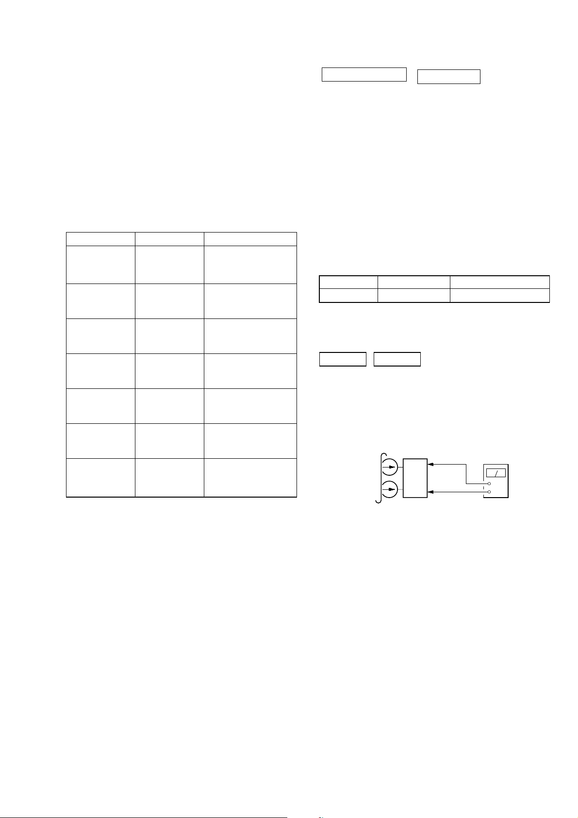
set
MAIN board
CN510
Pin
1
(L-CH)
Pin
3
(R-CH)
MAIN board
CN510
Pin
2
(GND)
+
–
level meter
test tape
P-4-A100
(10 kHz, –10 dB)
SECTION 5
MECHANICAL ADJUSTMENTS
Precaution
1. Clean the following parts with a denatured alcohol-moistened
swab:
record/playback heads pinch rollers
erase head rubber belts
capstan idlers
2. Demagnetize the record/playback head with a head
demagnetizer.
3. Do not use a magnetized screwdriver for the adjustments.
4. After the adjustments, apply suitable locking compound to
the parts adjusted.
5. The adjustments should be performed with the rated power
supply voltage unless otherwise noted.
Torque Measurement
Mode Torque meter Meter reading
3.06 N • m to 6.96 N • m
FWD CQ-102C 31 to 71 g • cm
(0.43 – 0.98 oz • inch)
FWD
back tension
REV CQ-102RC 31 to 71 g • cm
REV
back tension
FF/REW CQ-201B 71 to 143 g • cm
FWD tension CQ-403A 100 g or more
REV tension CQ-403R 100 g or more
CQ-102C 2 to 6 g • cm
CQ-102RC 2 to 6 g • cm
0.19 N • m to 0.58 N • m
(0.02 – 0.08 oz • inch)
3.06 N • m to 6.96 N • m
(0.43 – 0.98 oz • inch)
0.19 N • m to 0.58 N • m
(0.02 – 0.08 oz • inch)
6.96 N • m to 14.02 N • m
(0.98 – 1.99 oz • inch)
9.80 N • m
(3.53 oz or more)
9.80 N • m
(3.53 oz or more)
SECTION 6
ELECTRICAL ADJUSTMENTS
DECK SECTION
1. Demagnetize the record/playback head with a head
demagnetizer.
2. Do not use a magnetized screwdriver for the adjustments.
3. After the adjustments, apply suitable locking compound to the
parts adjust.
4. The adjustments should be performed with the rated power
supply voltage unless otherwise noted.
5. The adjustments should be performed in the order given in
this service manual. (As a general rule, playback circuit
adjustment should be completed before performing recording
circuit adjustment.)
6. The adjustments should be performed for both L-CH and RCH.
7. Switches and controls should be set as follows unless otherwise
specified.
•Test Tape
Tape Signal Used for
P-4-A100 10 kHz, –10 dB Azimuth Adjustment
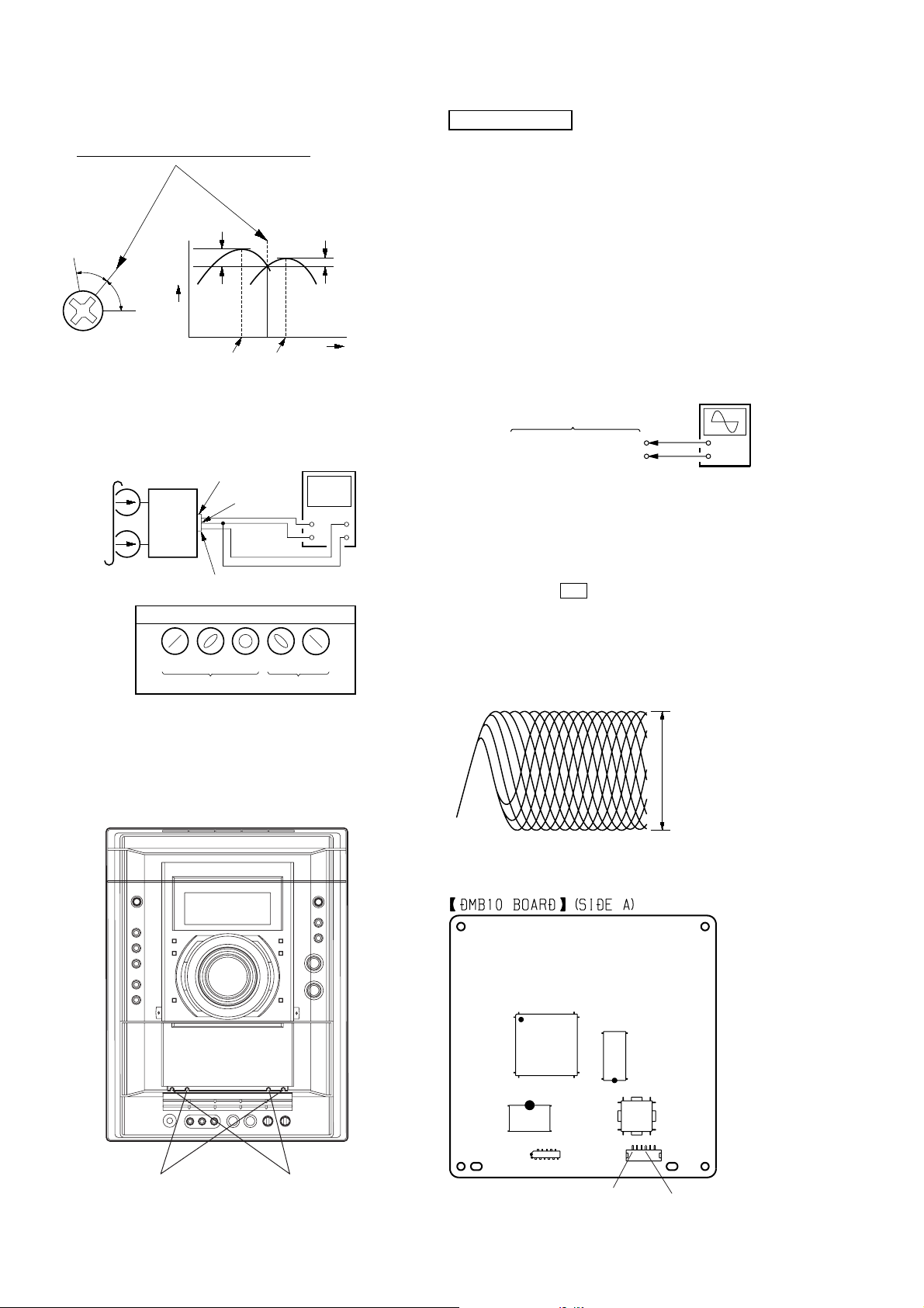
RECORD/PLAYBACK HEAD AZIMUTH ADJUST-MENT
DECK A DECK B
Note: Perform this adjustments for both decks
Procedure:
1. Mode: Playback
0 dB=0.775 V
27
HCD-GNV99D/GNV111D
e
2. Turn the adjustment screw and check output peaks. If the peaks
do not match for L-CH and R-CH, turn the adjustment screw
so that outputs match within 1dB of peak.
Output
level
within
1dB
L-CH
peak
R-CH
peak
within
1dB
Screw
position
L-CH
peak
Screw
position
R-CH
peak
3. Mode: Playback
test tape
P-4-A100
(10 kHz, –10 dB)
L-CH
MAIN
board
CN510
set
R-CH
waveform of oscilloscope
in phase 45°90°135°180
pin
L
R
pin
good
1
pin
3
2
oscilloscop
V
wrong
H
°
4. After the adjustments, apply suitable locking compound to
the pats adjusted.
Adjustment Location: Playback Head (Deck A).
Record/Playback/Erase Head (Deck B).
DVD SECTION
AUTO SERVO ADJUSTMENT
After parts related to the servo circuit (RF amplifier , DSP (IC102),
motor driver (IC201), EEPROM (IC103) so on) are replaced, readjusting the servo circuit is necessary.
[TEST DISC LIST]
Use the following test disc on test mode.
TDV-520CSO (DVD-SL): PART No. J-2501-236-A
LUV-P01 (CD): PART No. 4-999-032-01
TDV-540C (DVD-DL): PART No. J-2501-235-A
Note: Do not use exiting test disc for DVD.
[RFMON Level Check]
Connection:
oscilloscope
DMB10 board
CN105 pin 6 (RFMON)
CN105 pin
3
(GND)
Procedure:
1. Connect an oscilloscope to CN105 pin 6 (RFMON) and
CN105 pin 3 (GND) on the DMB10 board.
2. Turn the power on.
3. Set the test disc (DVD: TDV-520CSO, CD: LUV-P01) on the
tray and press H button to playback.
4. Confirm that oscilloscope waveform is clear and check
RFMON signal level is correct or not.
Note: A clear RFMON signal waveform means that the shape “◊” can be
clearly distinguished at the center of the waveform.
RFMON signal waveform
0.8 ± 0.2 Vp-p (CD)
+
–
VOLT/DIV: 200 mV
TIME/DIV: 500 ns
level: 0.8 ± 0.2 Vp-p (DVD)
28
forward reverse
Checking Location: DMB10 board (Side A)
IC104
IC102
CN105
IC201
6
1
CN105 pin 3 (GND)
IC101
CN106
CN105 pin 6 (RFMON)

SECTION 7
R
MAIN board
MIC board
JOG board
PANEL board
MOTOR (LD) board
SW board
SENSOR board
DRIVER board
MOTOR (TB) board
DIAGRAMS
HCD-GNV99D/GNV111D
For Schematic Diagrams.
Note:
• All capacitors are in µF unless otherwise noted. (p: pF)
• All resistors are in Ω and 1/
•%: indicates tolerance.
• f : internal component.
• 2 : nonflammable resistor.
• 5 : fusible resistor.
• C : panel designation.
• A : B+ Line.
• B : B– Line.
•Voltages and waveforms are dc with respect to ground un-
•Voltages are taken with a VOM (Input impedance 10 MΩ).
•Waveforms are taken with a oscilloscope.
• Circled numbers refer to waveforms.
• Signal path.
50 V or less are not indicated except for electrolytics and
tantalums.
specified.
Note:
The components identified by mark 0 or dotted line
with mark 0 are critical for safety.
Replace only with part number specified.
der no-signal (detuned) conditions.
DMB10 and VIDEO boards
no mark : DVD PLAY
Other board
no mark : TUNER (FM/AM)
( ) : DVD PLAY
< > : TAPE PLAY
[ ] : TAPE REC
* : Impossible to measure
Voltage variations may be noted due to normal production
tolerances.
Voltage variations may be noted due to normal production
tolerances.
F : AUDIO
e : TUNER
k : TAPE PLAY (DECK A)
d : TAPE PLAY (DECK B)
G : REC (DECK B)
J : CD PLAY
N : MIC
c : DVD PLAY
L : VIDEO
E : Y
a : CHROMA
r : COMPONENT VIDEO
q : R, G, B
4
W or less unless otherwise
Note on Printed Wiring Boards.
Note:
• X : parts extracted from the component side.
• : Pattern from the side which enables seeing.
(The other layers' patterns are not indicated.)
Caution:
Pattern face side: Parts on the pattern face side seen from
(SIDE A) the pattern face are indicated.
Parts face side: Parts on the parts face side seen from
(SIDE B) the parts face are indicated.
• Indication of transistor.
C
Q
B
E
Q
B
CE
Q
B
CE
•Abbreviation
AUS: Australian model
E2 : 120V AC Area in E model
E3 : 240V AC Area in E model
E15 : Iran model
EA : Saudi Arabia model
MY : Malaysia model
PH : Philippines model
SP : Singapore model
These are omitted.
These are omitted.
These are omitted.
• Circuit Boards Location
CD-SW board
TRANS board
DMB10 board
VIDEO board
PRIMARY board
TUNER PACK
SWITCHING POWE
DVD SURR board
PA board
HCD-GNV99D/GNV111D
2929

HCD-GNV99D/GNV111D
7-1. BLOCK DIAGRAM – RF SECTION –
RF
A
CD LD
PD
DVD LD
WR650
VR780
B
C
D
F
E
Q102 (1/2)
AUTOMATIC POWER
CONTROL (FOR CD)
Q102 (2/2)
AUTOMATIC POWER
CONTROL (FOR DVD)
Q101
Q103
DETECTOR
OPTICAL PICK-UP
BLOCK
(KHM-310CAB)
LASER
DIODE
(FOR CD)
LASER
DIODE
(FOR DVD)
6
2
3
4
5
19
18
8
9
10
11
23
20
21
22
187
DVDRFIP
DVDA
DVDB
DVDC
DVDD
TPI
TNI
NA
NB
MC
MD
LD01
MDI2
MDI1
LD02
MSW
OSP
252 253
OSN
IC102 (1/2)
CD/DVD RF AMP,
FOCUS/TRACKING ERROR AMP
DVD SYSTEM PROCESSOR
DIGITAL SERVO PROCESSOR
ASDATA0
ASDATA1
ASDATA2
ASDATQ3
ACLK
ABCK
ALRCK
XRST
SDA
SCL
217
218
219
222
215
214
213
220
103
102
14
SDTI1
15
SDTI2
16
SDTI3
13
SDTI4
10
MCLK
9
BICK
17
LRCK
8
PDN
CONVERTER
20
SDA
19
CSL
SDA
5
SCL
6
IC301
D/A
IC103
EEPROM
LOUT4+
LOUT4-
ROUT4+
ROUT4-
LOUT1+
LOUT1-
ROUT1+
ROUT1-
LOUT3+
LOUT3-
ROUT3+
ROUT3-
LOUT2+
LOUT2-
ROUT2+
ROUT2-
IC3771 AMP
38
37
33
32
2
1
48
47
42
41
40
39
46
45
44
43
(IC3711,3731,3751,3771)
3
2
5
6
IC3711 AMP
3
2
5
6
IC3751 AMP
3
2
5
6
IC3731 AMP
3
2
5
6
BIAS
Q3801
BIAS
1
7
1
7
1
7
1
7
DM_L
DM_R
MB_FL
MB_FR
FC
SW(LEE)
MB_SL
MB_SR
AU+5V
A
MAIN
SECTION
(Page 33)
2AXIS
DEVICE
FOCUS/
TRACKING
COIL
FCS+
FCS–
TRK+
TRK–
M2
(SLED)
M1
(SPINDLE)
S1
(LIMIT)
MM
MM
REG01
SP+
SP–
REG02
SL–
SL+
FOCUS/TRACKING COIL DRIVER,
IC201
SPINDLE, SLED MOTOR DRIVER
42
NC
41
NC
36 48
37 1
35 3
34 4
32
31
30
29
27
28
46
47
BUFFER
FOCUS COIL
DRIVE
TRACKING COIL
DRIVE
SLED MOTOR
DRIVE
SLED MOTOR
DRIVE
SPINDLE MOTOR
DRIVE
BUFFER
15
SCKI
BCK
LRCK
DOUT
IC3601
D/A
CONVERTER
DISPLAY/POWER
B
IC401 (1/6)
SYSTEM
CONTROLLER
11
10
TXD
RXD
PRST
IFCK
IFSDO
IFSDI
XIFCS
IFBSY
MREQ
209
107
106
28
110
99
98
101
100
105
205
207
114
SPDATA/SMSDI
9
12
43
10
13
42
40
21
19
20
22
45
VREFO
FOO
TRO
FMO
DMO
IOP
IOPMON
VREFO
FMO
FOO
DMO
TRO
30
38
42
37
41
40
184
183
181
47
176
VREFO
FMO
FOO
DND
TRO
IOPMON
MUTE123
MUTE
TSDM
SPFG
LIMSW
V2 REF0
MIC/VSYNC
KRMOD/HSYNC
12
CN105
1
TXD
2
RXD
5
V2REF0
6
RFMON
25
SYSRST
33
DVD_SCO/CLK1
32
DVD_SOD/RXD1
31
DVD_SID/TXD1
24
XIFCS
23
IFBUSY
21
MIC SW
18
KRMOD
22
MREQ
TXD1
RXD1
CLK1
LIN
RIN
SECTION
(Page 35)
1
2
LIN
RIN
F
MAIN
SECTION
(Page 33)
• Signal Path
: CD PLAY
: DVD PLAY
HCD-GNV99D/GNV111D
3030
 Loading...