

Sony HCD-GN800 Service Manual
HCD-GN800
SERVICE MANUAL
Ver 1.1 2003.06
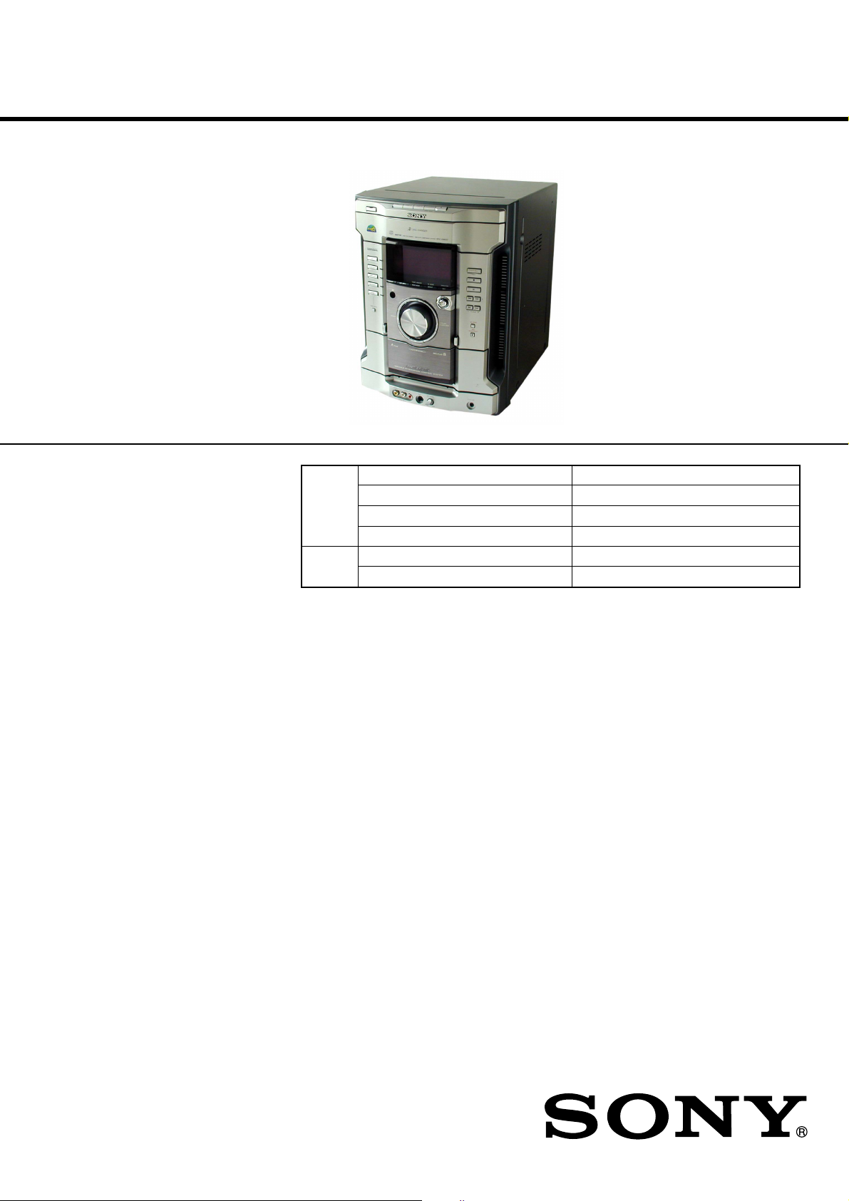
HCD-GN800 is the amplifier, CD player,
tape deck and tuner section in MHCGN800.
Model Name Using Similar Mechanism NEW
CD
Section
TAPE
Section Tape Transport Mechanism Type CWM43RR23
CD Mechanism Type CDM74-K6BD47S
Base Unit Name BU-K6BD47S
Optical Pick-up Name KSM-213DCP
Model Name Using Similar Mechanism HCD-XGR88
E Model
Australian Model
Amplifier section
The following are measured at AC 127V, 60 Hz
(Mexican model only)
The following are measured at AC 120, 220, 240V
50/60 Hz (except Mexican model)
DIN power output (rated) 170 + 170 watts
(6 ohms at 1 kHz, DIN)
Continuous RMS power output (reference)
220 + 220 watts
(6 ohms at 1 kHz, 10% THD)
Inputs
GAME (VIDEO): 1 Vp-p, 75 ohms
(phono jack)
GAME (AUDIO): Voltage 250 mV,
(phono jacks) impedance 47 kilohms
MD/VIDEO (AUDIO) IN: voltage 450 mV/250 mV,
(phono jacks) impedance 47 kilohms
MIC: sensitivity 1 mV,
(phone jack) impedance 10 kilohms
Outputs
VIDEO OUT: max. output level 1 Vp-p,
(phono jacks) unbalanced, Sync.
negative load impedance 75 ohms
PHONES: accepts headphones of
(stereo mini jack) 8 ohms or more
FRONT SPEAKER: accepts impedance of 6 to 16 ohms
SURROUND SPEAKER: accepts impedance of 24 ohms or more
SPECIFICATIONS
CD player section
System Compact disc and digital audio system
Laser Semiconductor laser
(λ=795nm)
Laser Output Max. 44.6 µW*
*This output is the value measured at a
distance of 200 mm from the objective
lens surface on the Optical Pick-up
Block with 7 mm aperture.
Frequency response 2 Hz – 20 kHz (±0.5 dB)
Wave length 795 nm
CD OPTICAL DIGITAL OUT
(Square optical connector jack, rear panel)
Wave length 660 nm
Output Level –18 dBm
Tape player section
Recording system 4-track 2-channel stereo
Frequency response 50 – 13,000 Hz (±3 dB), using Sony
TYPE I cassette
– Continued on next page –
9-877-275-02 Sony Corporation
2003F02-1 Home Audio Company
C 2003.06 Published by Sony Engineering Corporation
MiNi Hi-Fi COMPONENT SYSTEM
HCD-GN800
Ver 1.1 2003.06
Tuner section
FM stereo, FM/AM superheterodyne tuner
FM tuner section
Tuning range 87.5 – 108.0 MHz
Antenna FM lead antenna
Antenna terminals 75 ohm unbalanced
Intermediate frequency 10.7 MHz
AM tuner section
Tuning range
Latin Americanmodels: 530 – 1,710 kHz
(with the interval set at 10 kHz)
531 – 1,710 kHz
(with the interval set at 9 kHz)
Middle Eastern models: 531 – 1,602 kHz
(with the interval set at 9 kHz)
Other models: 531 – 1,602 kHz
(with the interval set at 9 kHz)
530 – 1,710 kHz
(with the interval set at 10 kHz)
Antenna AM loop antenna
Antenna terminals External antenna terminal
Intermediate frequency 450 kHz
General
Power requirements
Mexican models: 120V or 127V AC, 60 Hz
Argentina models: 220 V AC, 50/60 Hz
Australian model: 240V AC, 50/60 Hz
Other models: 120 V, 220 V or 230 - 240 V AC, 50/60 Hz
Adjustable with voltage selector
Power consumption 250 watts
Dimensions (w/h/d) Approx. 280 x 360 x 386.5 mm
Mass : Approx. 13.6 kg
Notes on chip component replacement
• Never reuse a disconnected chip component.
• Notice that the minus side of a tantalum capacitor may be damaged by heat.
Flexible Circuit Board Repairing
• Keep the temperature of the soldering iron around 270 ˚C during repairing.
• Do not touch the soldering iron on the same conductor of the
circuit board (within 3 times).
• Be careful not to apply force on the conductor when soldering
or unsoldering.
CAUTION
Use of controls or adjustments or performance of procedures
other than those specified herein may result in hazardous radiation exposure.
This appliance is classified as
a CLASS 1 LASER product.
The CLASS 1 LASER
PRODUCT MARKING is
located on the rear exterior.
Design and specifications are subject to change without notice.
SAFETY-RELATED COMPONENT WARNING!!
COMPONENTS IDENTIFIED BY MARK 0 OR DOTTED
LINE WITH MARK 0 ON THE SCHEMATIC DIAGRAMS
AND IN THE PARTS LIST ARE CRITICAL TO SAFE
OPERATION. REPLACE THESE COMPONENTS WITH
SONY PARTS WHOSE PART NUMBERS APPEAR AS
SHOWN IN THIS MANUAL OR IN SUPPLEMENTS PUBLISHED BY SONY.
2

TABLE OF CONTENTS
HCD-GN800
1. SERVICING NOTES ................................................ 4
2. GENERAL
Location of Controls ....................................................... 5
3. DISASSEMBLY
3-1. Case ................................................................................. 8
3-2. Loading (Panel) ............................................................... 8
3-3. Front Panel Assy ............................................................. 9
3-4. Tuner Pack, Sub Trans Board ......................................... 9
3-5. CD Mechanism Deck ...................................................... 10
3-6. Game In Board, Tape Mechanism Deck......................... 10
3-7. CD Switch Board, Display Board .................................. 11
3-8. Volume Board.................................................................. 11
3-9. Subwoofer Board, Rear Panel ........................................ 12
3-10. Main Board...................................................................... 12
3-11. Power Amp Board ........................................................... 13
3-12. SW Board, Driver Board................................................. 13
3-13. CD Board, CD Block Assy ............................................. 14
3-14. Sensor Board ................................................................... 14
3-15. Motor (TB) Board ........................................................... 15
3-16. Motor (LD) Board ........................................................... 15
4. TEST MODE.............................................................. 16
5. MECHANICAL ADJUSTMENTS....................... 20
7-14. Schematic Diagram – Display Board – ......................... 43
7-15. Printed Wiring Board – Power Amp Board – ................ 44
7-16. Schematic Diagram – Power Amp Board – .................. 45
7-17. Printed Wiring Board – Subwoofer Board – ................. 46
7-18. Schematic Diagram – Subwoofer Board – .................... 47
7-19. Printed Wiring Boards – T rans Board – ........................ 48
7-20. Schematic Diagram – Trans Board – ............................. 49
7-21. IC Block Diagram ........................................................... 50
7-22. IC Pin Function Description ........................................... 51
8. EXPLODED VIEWS
8-1. Case, Rear Panel Section ................................................ 56
8-2. Front Panel Section ......................................................... 57
8-3. Chassis Section ............................................................... 58
8-4. CD Mechanism Deck Section-1
(CDM74-K6BD47S) ....................................................... 59
8-5. CD Mechanism Deck Section-2
(CDM74-K6BD47S) ....................................................... 60
9. ELECTRICAL PARTS LIST ............................... 61
6. ELECTRICAL ADJUSTMENTS
Deck section .................................................................... 20
CD Section ...................................................................... 22
7. DIAGRAMS
7-1. Circuit Board Location ................................................... 26
7-2. Block Diagram – CD Servo Section –........................... 28
Block Diagram – Tuner/Tape Deck Section – ............... 29
Block Diagram – Main/Power Section –....................... 30
Block Diagram – Display Section – .............................. 31
7-3. Printed Wiring Board – CD Board – ............................. 32
7-4. Schematic Diagram – CD Board – ................................ 33
7-5. Printed Wiring Board – CD Mechanism Board – ......... 34
7-6. Schematic Diagram – CD Mechanism Board – ............ 35
7-7. Printed Wiring Boards – Main Board –......................... 36
7-8. Schematic Diagram – Main Board (1/3) – .................... 37
7-9. Schematic Diagram – Main Board (2/3) – .................... 38
7-10. Schematic Diagram – Main Board (3/3) – .................... 39
7-11. Printed Wiring Boards
– Game In, CD Switch Board – ...................................... 40
7-12. Schematic Diagram
– Game In, CD Switch Board – ...................................... 41
7-13. Printed Wiring Board – Display Board – ...................... 42
3
HCD-GN800
SECTION 1
SERVICING NOTES
NOTES ON HANDLING THE OPTICAL PICK-UP
BLOCK OR BASE UNIT
The laser diode in the optical pick-up block may suffer electrostatic break-down because of the potential difference generated
by the charged electrostatic load, etc. on clothing and the human
body.
During repair, pay attention to electrostatic break-down and also
use the procedure in the printed matter which is included in the
repair parts.
The flexible board is easily damaged and should be handled with
care.
NOTES ON LASER DIODE EMISSION CHECK
The laser beam on this model is concentrated so as to be focused
on the disc reflective surface by the objective lens in the optical
pick-up block. Therefore, when checking the laser diode emission, observe from more than 30 cm away from the objective lens.
LASER DIODE AND FOCUS SEARCH OPERATION
CHECK
Carry out the “S curve check” in “CD section adjustment” and
check that the S curve waveforms is output three times.
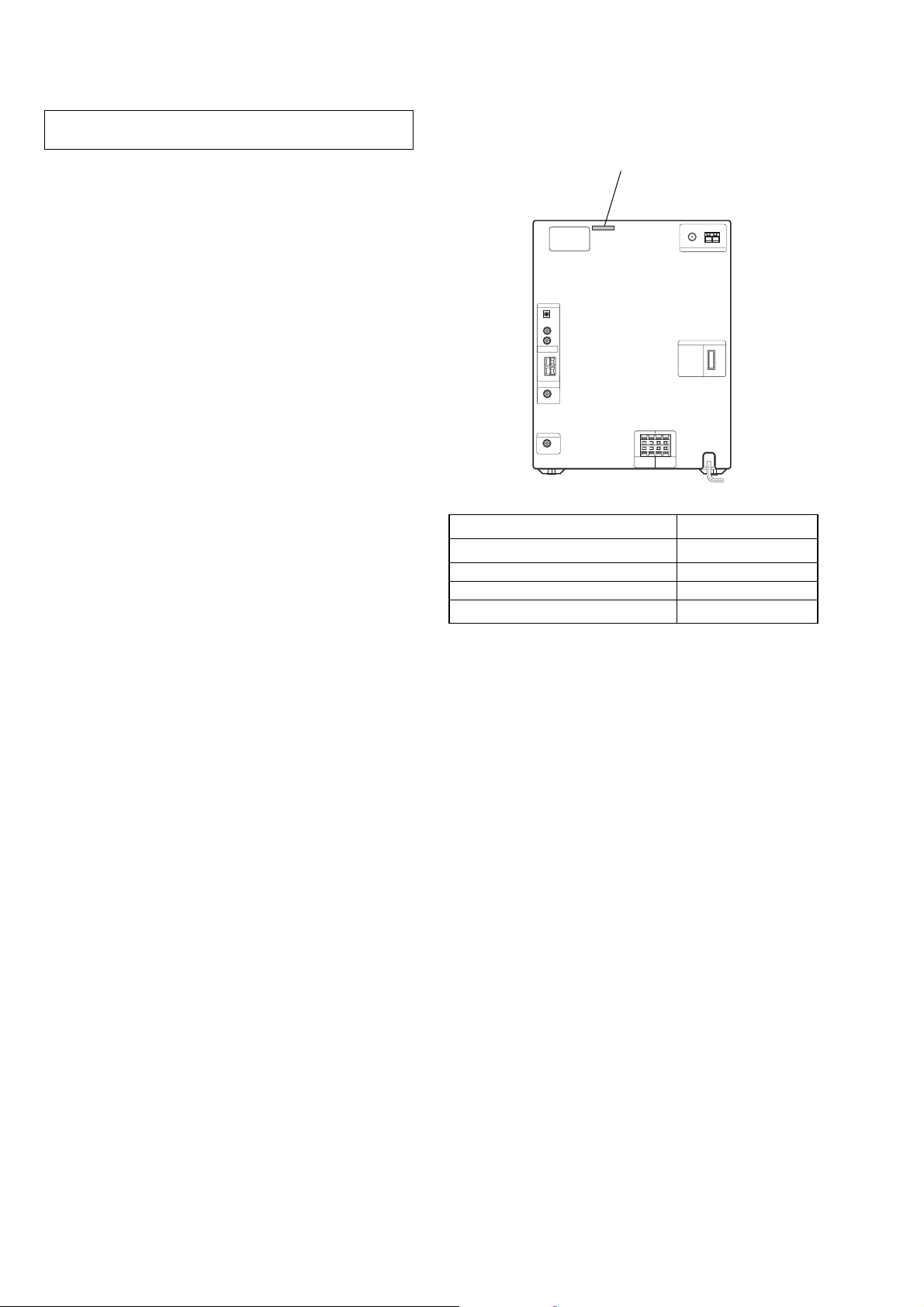
• MODEL IDENTIFICATION
– Back Panel –
PA RT No.
MODEL PART No.
E2, E3models 4-244-107-0
E51 model 4-244-107-1
Mexican model 4-244-107-2
Argentina model 4-244-107-3
[]
[]
[]
[]
• Abbreviation
E2 : 120 V AC Area in E model
E3 : 240 V AC Area in E model
E51 : Chilean and Peruvian model
4
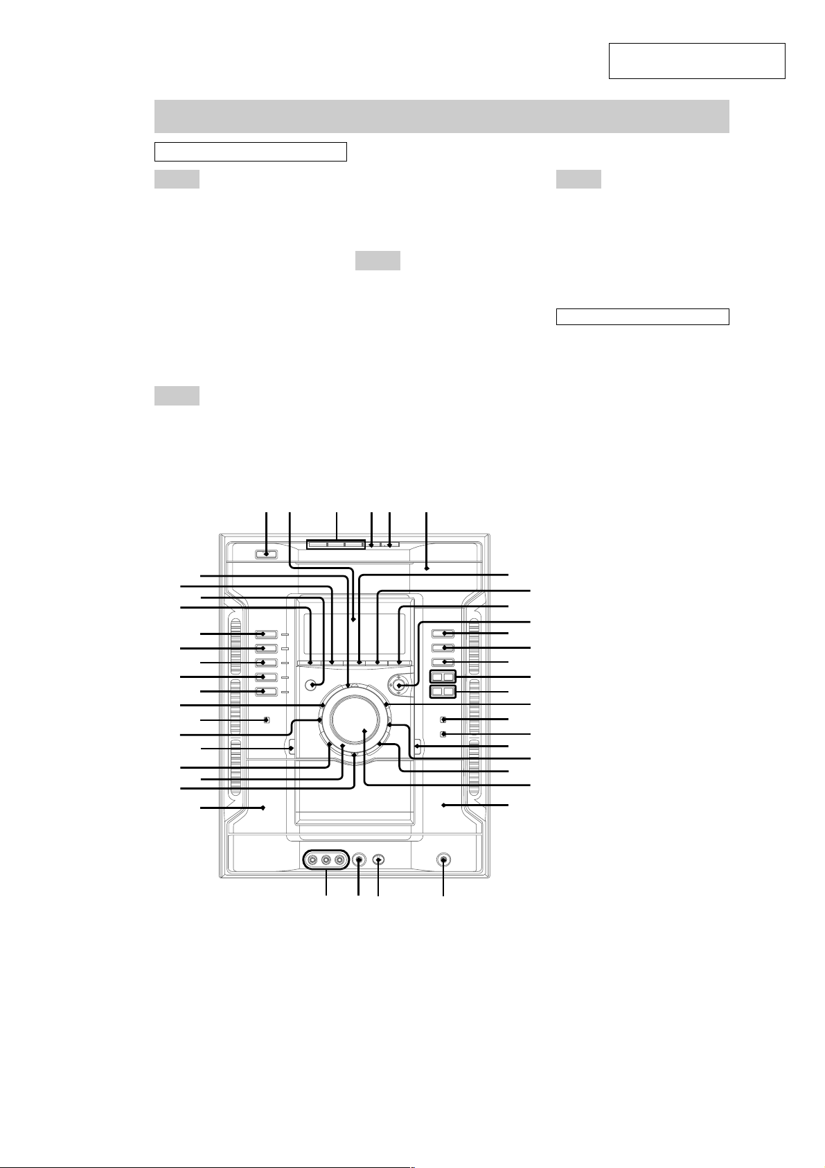
Main unit
ALPHABETICAL ORDER
A - D
ALBUM +/- qg
AMP MENU rd
CD r;
CD SYNC qj
DECK A wk
DECK B wd
DIRECTION 9
DISC 1~3 3
DISC SKIPEX-CHANGE 4
Disc tray 6
DISPLAYra
Display 2
E - L
EDIT 9
EFFECT ON/OFF rf
FM MODE 8
GAME eh
GAME EQ ea
SECTION 2
GENERAL
GAME INPUT (jacks) wj
GAME MIXING ef
GROOVE ed
IR (receptor) rs
ILLUMINATION wl
M - Q
MD (VIDEO) ej
MIC (jack) wh
MIC LEVE L wg
MOVIE EQ qh
MUSIC EQ eg
OPEN/CLOSE Z 5
P FILE wa
PHONES (jack) wf
PLAY MODE 7
Power illuminator e;
PUSH ENTER q;
4 5 61 2 3
HCD-GN800
This section is extracted from
instruction manual.
R - Z
REC PAUSE/START qk
REPEAT 8
SURROUND SPEAKER MODE
TAPE A/B ek
TUNER/BAND el
TUNER MEMORY 7
VOLUMEws
SYMBOLS
@/1 (power) 1
hH (play) qa
x (stop) qs
X (pause) qd
- . (go backward) qf
> + (go forward) qf
m (rewind) qg
M (fast forward) qg
V/v/B/b q;
A A (Eject A) es
A B (Eject B) ql
w;
r
r
e
ej
eg
ed
ea
wl
rf
d
r
s
a
r;
l
e
k
eh
ef
es
e;
wk
wj
wgwh
wf
7
9
qa
qd
qg
qj
q
wa
wd
8
0
qs
qf
qh
qk
l
w;
ws
5
HCD-GN800
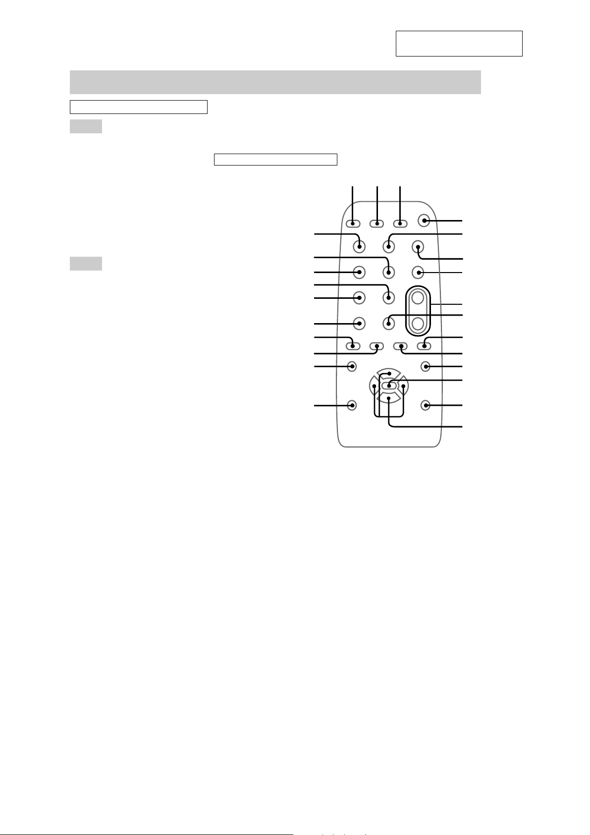
Remote Control
ALPHABETICAL ORDER
This section is extracted from
instruction manual.
A - M
CD ql
CLEAR 7
CLOCK/TIMER SELECT 2
CLOCK/TIMER SET 3
D.SKIP 9
ENTER qd
EFFECT ON/OFF qf
GAME w;
MD (VIDEO) q;
P - Z
PRESET - wd
PRESET + wf
PRESET EQ qj
P FILE qh
SURROUND SPEAKER MODE
SLEEP 1
TAPE A/B qa
TUNER/BAND qk
TUNING - wa
TUNING + ws
VOL +/- 8
SYMBOLS
@/1 (power) 4
nN (p
X (pause) 5
x (stop) 6
.(go backward) wd
> (go forward) wf
m (rewind) wa
M (fast forward) ws
M/m/</, qg
qs
lay)
wg
wg
wf
wd
ws
wa
w;
ql
qk
qj
qh
123
4
5
6
7
8
9
q;
qa
qs
qd
qf
qg
6
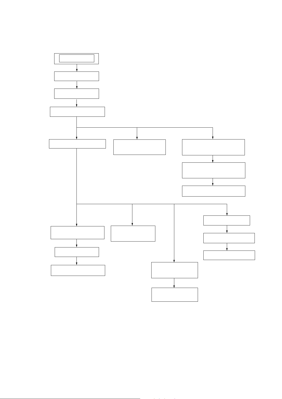
• This set can be disassembled in the order shown below.
SET
CASE
LOADING (PANEL)
FRONT PANEL ASSY
HCD-GN800
SECTION 3
DISASSEMBLY
CD MECHANISM DECK
SUBWOOFER BOARD
REAR PANEL
MAIN BOARD
POWER AMP BOARD
TUNER PACK,
SUB TRANS BOARD
SW BOARD,
DRIVER BOARD
CD BLOCK ASSY
GAME IN BOARD,
TAPE MECHANISM DECK
CD SWITCH BOARD,
DISPLAY BOARD
VOLUME BOARD
SENSOR BOARD
MOTOR (TB) BOARD
MOTOR (LD) BOARD
CD BOARD,
OPTICAL PICK-UP
(KSS-213DCP)
7
HCD-GN800
)
Note: Follow the disassembly procedure in the numerical order given.
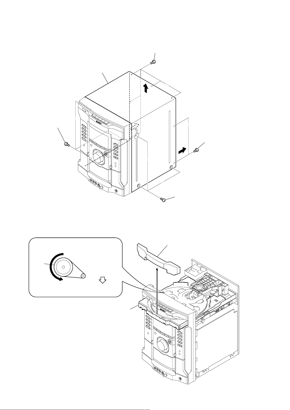
3-1. CASE
6
Case
1
Three screws
(case 3 TP2)
2
Five screws
(+BVTT3 x 6)
5
4
3
T wo screws
(+BVTT3 x 6
3-2. LOADING (PANEL)
CD mechanismdeck (CDM74-K6BD47S)
1
Turn the pulley to the arrow direction.
Pulley
Front side
Pull out disc tray
2
4
3
1
Three screws
(case 3 TP2)
Loading (panel)
8
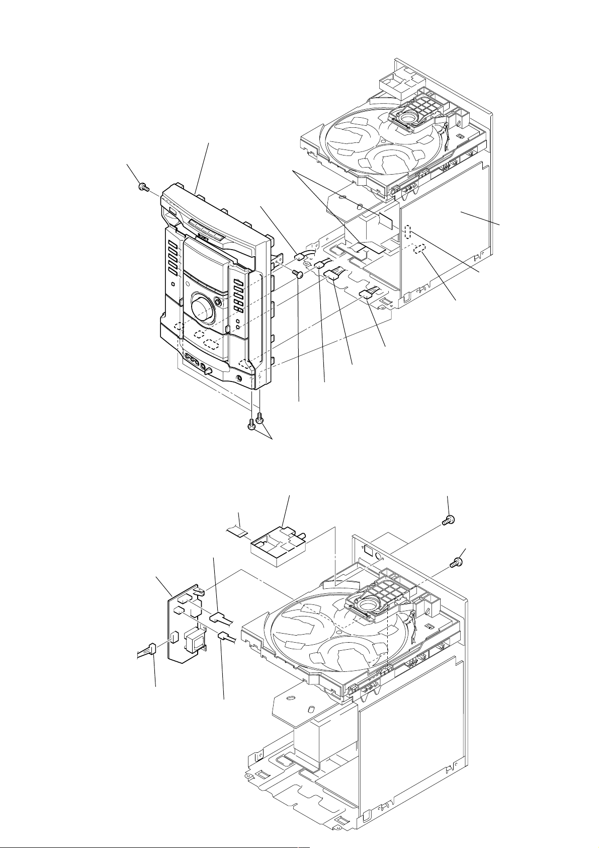
3-3. FRONT PANEL ASSY
d
8
3
Screw (BVTP3 x 10)
Front panel ASSY
1
(flat type)
7
From CN607 on
Game in board
HCD-GN800
T wo wires
MAIN boar
CN402
CN304
2
Four screws (BVTP3 x 10)
3-4. TUNER PACK, SUB TRANS BOARD
1
Wire (flat type)
(11 core)
4
CN971
8
Sub trans board
6
From deck A head
3
Screw (BVTP3 x 10)
3
T uner pack
4
From deck B head
5
From CN606 on Game in board
2
Two screw (BVTP3 x 10)
7
Three screws
(BVTP3 x 10)
6
CN976
5
CN974
9
HCD-GN800
)
)
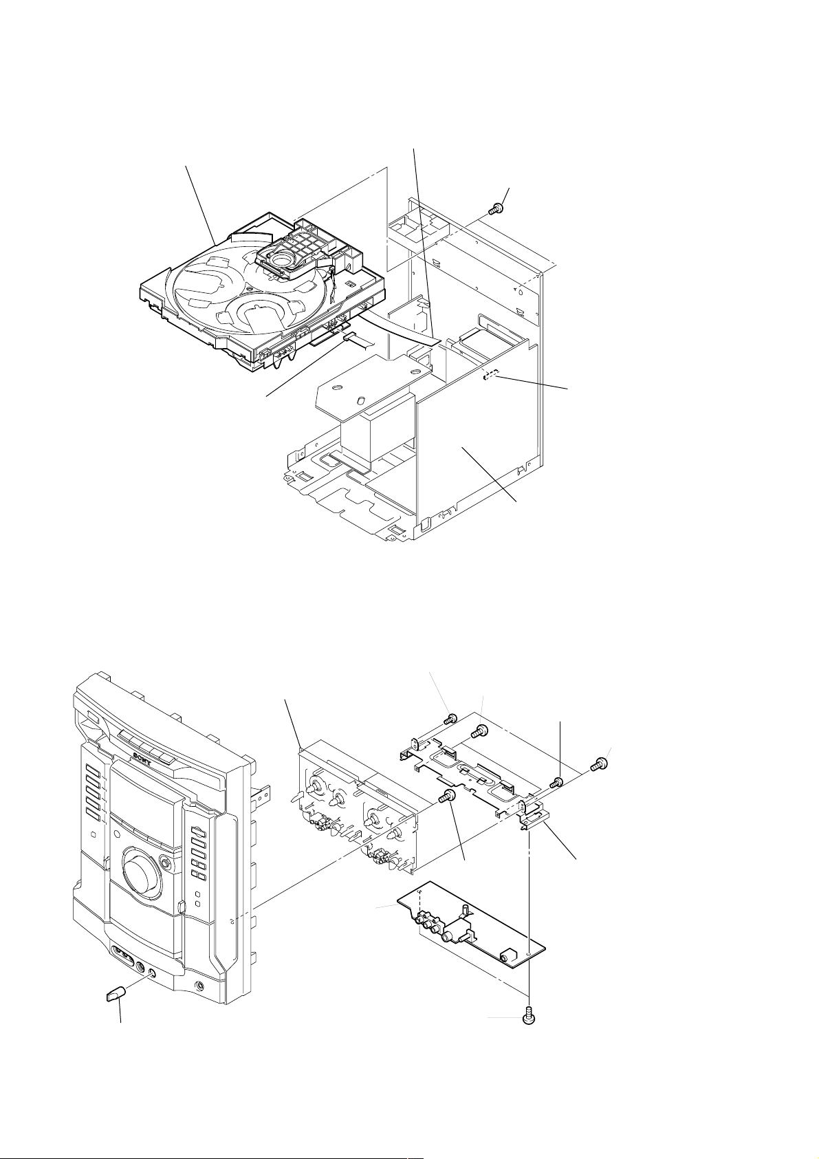
3-5. CD MECHANISM DECK
4
CD mechanism deck
3
CN701
2
Wire (flat type) (31 core)
1
Two screws (BVTP3 x 10
CN201
3-6. GAME IN BOARD, TAPE MECHANISM DECK
8
Tape mechanism deck
2
Screw (+PTT2 x 4)
7
Three screws
(+BVTP2.6 x 8)
MAIN board
4
Two screws (+BVTP2.6 x 8)
2
Screw (+PTT2 x 4)
3
T wo screws
(+BVTP2.6 x 8
Shield plate (GHX)
10
1
Knob (MIC)
6
GAME IN board
5
T wo screws
(+BVTP2.6 x 8)
3-7. CD SWITCH BOARD, DISPLAY BOARD
)
)
1
Six screws
(+BVTP2.6 x 8)
2
CD SWITCH board
4
Five screws
(+BVTP2.6 x 8)
5
3
Wire (flat type) (17 core)
from CN604
DISPLAY board
4
Five screws
(+BVTP2.6 x 8
HCD-GN800
3-8. VOLUME BOARD
1
Knob (VOL)
5
VOLUME board
4
Four claws
3
Three screws
(+BVTP2.6 x 8)
3
Three screws
(+BVTP2.6 x 8
2
Hexagonal nut
11
HCD-GN800
)
)
d
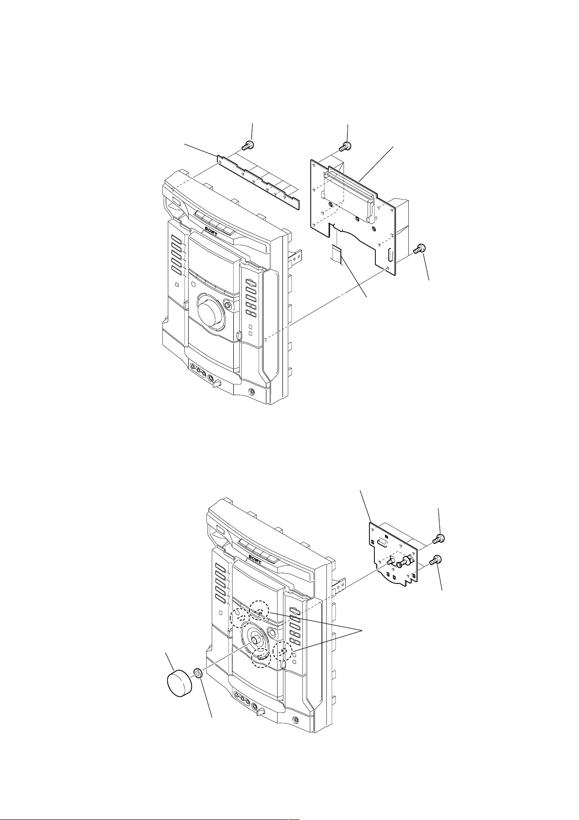
3-9. SUBWOOFER BOARD, REAR PANEL
0
Screw
(+BVTP3 x 10)
qs
SUBWOOFER board
CN303
qa
Bracket (IC)
9
T wo screws
(+BVTP3 x 16)
CN305
7
Connector
8
Connector
qd
with fan
6
Connector
Rear panel
1
T wo screws
(+BVTT3 x 6)
2
T wo screws
(+BVTP3 x 10
3
Three screws
(+BVTP3 x 10
4
Three screws
(+BVTP3 x 10)
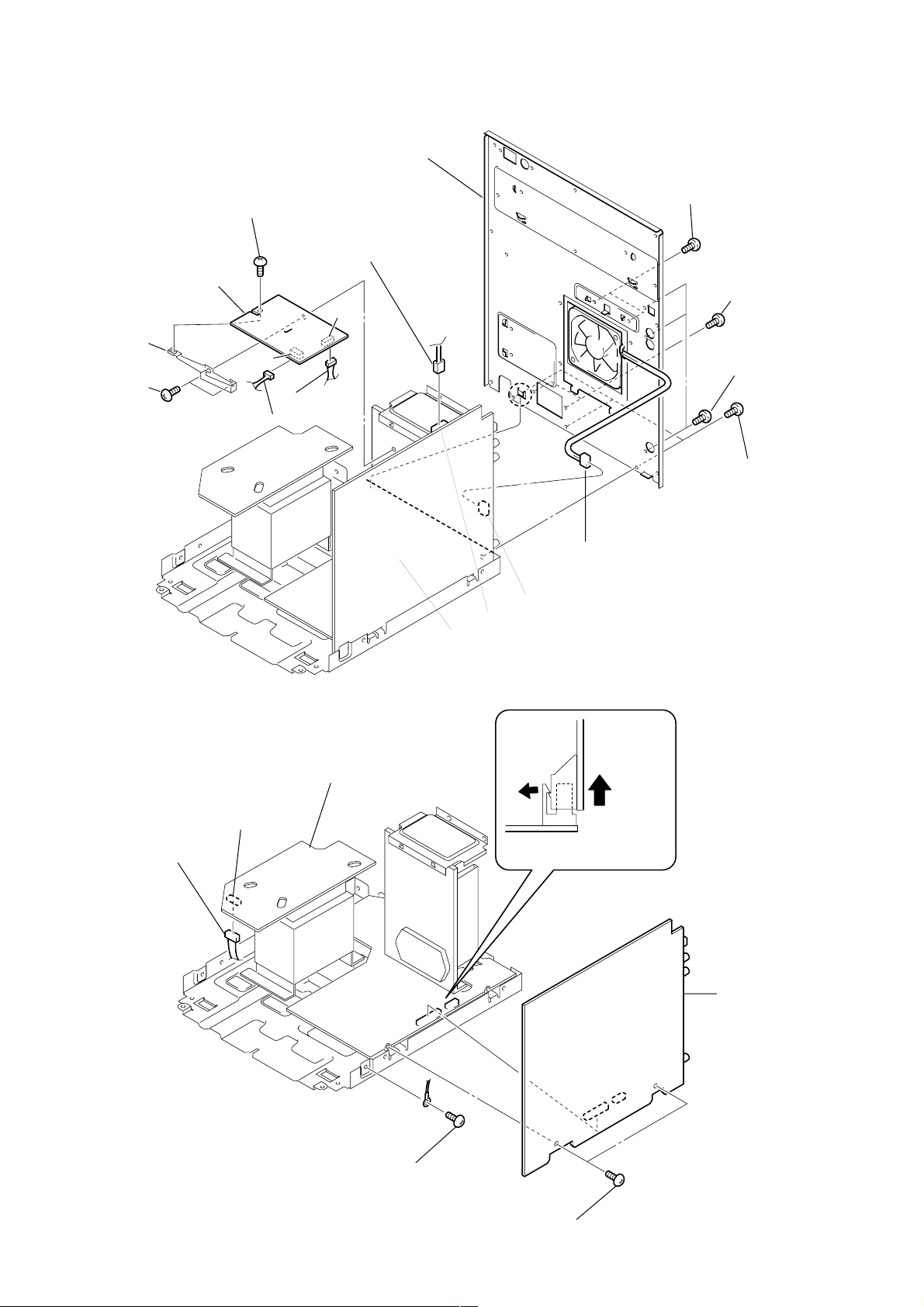
3-10. MAIN BOARD
1
Connector
CN998
TRAN board
CN1803
MAIN board
5
Connector
CN851
MAIN board
(CN901, 902)
4
POWER AMP board
(CN503, 504)
5
6
MAIN boar
12
2
Screw
(+BVTP3 x 10)
3
T wo screws
(+BVTP3 x 10)
3-11. POWER AMP BOARD
d
d
3
Bracket (HS)
2
T wo screws
(+BVTP3 x 10)
6
T wo screws
(+BVTP3 x 10)
4
T wo screws
(+BVTP3 x 10)
5
Three screws
(+BVTP3 x 10)
7
POWER AMP boar
HCD-GN800
1
Connector
from CN997
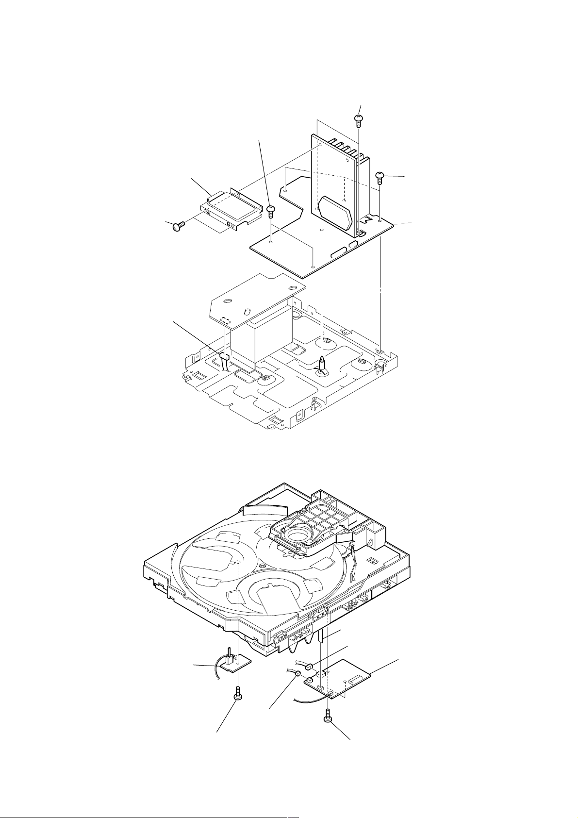
3-12. SW BOARD, DRIVER BOARD
2
SW board
3
1
Screw
(+BTTP (M2.6))
CN704
7
CN702 (flat type)
4
CN703
6
DRIVER boar
5
Two
screws
(+BTTP (M2.6))
13
HCD-GN800
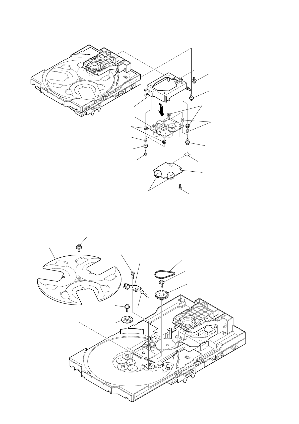
3-13. CD BOARD, CD BLOCK ASSY
9
(insulator)
8
2
Holder (213) ASSY
qh
CD block ASSY
0
Two
insulators
Two
coil springs
Two stoppers (BU)
qa
3
Floating
(+PTPWH M2.6)
1
(+PTPWH M2.6)
6
Two
5
(insulator)
4
Two floating
(+PTPWH M2.6)
Floating
insulators
Two
coil springs
screw
screw
screws
3-14. SENSOR BOARD
2
Tray
7
(BVTT M2.6)
qd
Remove the four solderings of motor.
1
Floating
(+PTPWH M2.6)
6
Floating
(+PTPWH M2.6)
screw
8
Screw
(+BTTP (M2.6))
screw
Two screws
9
SENSOR board
0
CN731
qf
CN708 (flat type)
qg
CD board
qs
Screw (+BTP 2.6x 8)
3
Belt (table)
4
Foating
(+PTPWH M2.6)
5
screw
Pulley (table)
14
7
Gear (geneva)
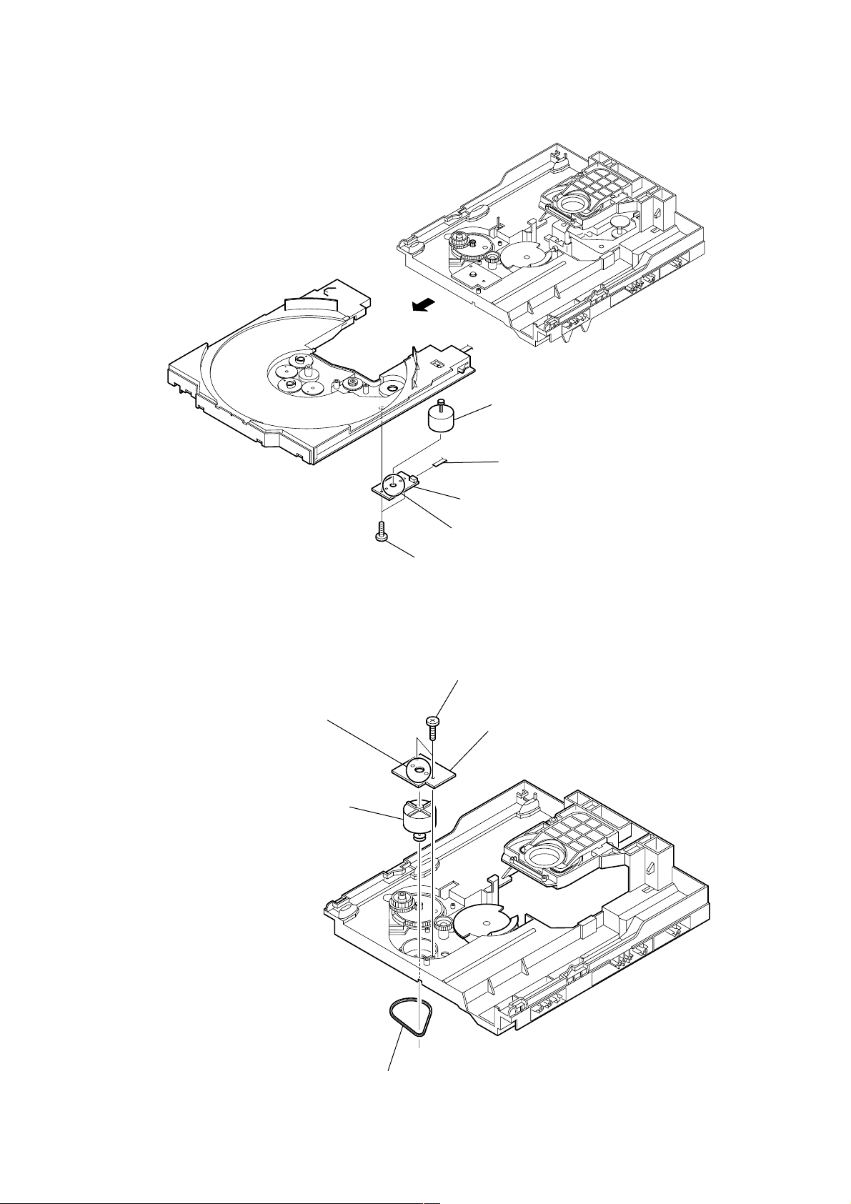
3-15. MOTOR (TB) BOARD
1
6
Table motor ASSY (M741)
HCD-GN800
3-16. MOTOR (LD) BOARD
4
Remove the two solderings of motor.
5
Loading motor ASSY (M751)
2
4
MOTOR (TB) board
5
Remove the two solderings of motor.
3
Two
screws
(+BTTP (M2.6))
2
Two
screws
(+BTTP (M2.6))
3
CN742 (flat type)
MOTOR (LD) board
1
Belt (loading)
15

HCD-GN800
SECTION 4
TEST MODE
[GC TEST MODE]
• This mode is used to check the fluorescent indicator tube, LED,
model, destination, software version, volume, key and VACS
level.
Procedure:
1. Press x button, [AMP MENU] button and [DISC 2] button
simultaneously.
2. All LEDs and segments in fluorescent indicator tube are lighted
up.
3. When you want to enter the software version display mode,
press
[DISC 1] b utton. The model and destination are displayed.
4. Each time
MC version, GC version, CD version, CDDM version, CDMA
version, CDMB version, BDA v ersion, BDB version, ST version,
T A version, TM v ersion and TC version in this order , and returns
to the MC version display.
5. When
are being displayed except model and destination, the date of
the software creation appear. When
again, the display returns to the software version display . When
[DISC 1] b utton is pressed, the display changes from
[DISC 3] button is pressed while the version numbers
[DISC 3] button is pressed
[DISC 1] b utton is pressed while the date of the software creation
is being displayed, the date of the software creation is displayed
in the same order of software version display.
6. Press
7. In the key check mode, the fluorescent indicator tube displays
8. When
9. When
10. T o release this mode, press three b uttons in the same manner as
[DISC 2] button, the key check mode is activated.
“K 0 V 0”.
Each time a button is pressed, “K” value increases. However,
once a button has been pressed, it is no longer taken into account.
“V” value increases in the manner of 0,1, 2, 3 ... if
knob is turned clockwise, or it decreases in the manner of 0, 9,
8,7 ... if
[VOLUME] knob is turned counter-clockwise.
[VOLUME]
[DISC 3] button is pressed after all LEDs and segments
in fluorescent indicator tube light up, the fluorescent indicator
tube displays “VACS A + B”. A is VACS level which is trigger
by signal level while B is VACS level which is trigger by thermal.
Total VACS value would be the sum of A and B.
[DISC SKIP/EX-CHANGE] button is pressed after all
LEDs and segments in fluorescent indicator tube light up,
alternate segments in fluorescent indicator tube would light up.
If you press
half of alternate segments in fluorescent indicator tube would
light up. Pressing
would case all segments lights up.
step 1, or disconnect the power cord.
[DISC SKIP/EX-CHANGE] button again, another
[DISC SKIP/EX-CHANGE] button again
[MC TEST MODE]
• This mode is used to check operations of the respective sections
of Amplifier, Tuner , and Tape.
Procedure:
* To enter MC Test Mode
1. Press x button, [AMP MENU] button and [DISC 3] button
simultaneously.
2. The TAPE A and TAPE B segments flash on the fluorescent
indicator tube. The function is changed to VIDEO.
* Check of Amplifier
1. When V button is pressed, GEQ increases to its maximum and
a message “GEQ MAX” appears on the fluorescent indicator
tube.
2. When v button is pressed, GEQ decreases to its minimum and
a message “GEQ MIN” appears on the fluorescent indicator
tube.
3. When B button or b button is pressed, GEQ is set to flat and
a message “GEQ FLAT” appears on the fluorescent indicator
tube.
4. When the
the sound volume increases to its maximum and a message
“VOLUME MAX” appears for two seconds, then the display
returns to the original display.
5. When the
slightly, the sound volume decreases to its minimum and a
message “VOLUME MIN” appears for two seconds, then the
display returns to the original display.
* Check of clock frequency
1. To check the frequency of clock used to run the clock of the
system, the clock output is available at IC501 pin ek (CLOCK-
OUT) on the MAIN board during MC test mode.
2. The frequency is 32.768 kHz.
* T ape function
1. When a tape is inserted in Deck B and recording is started, the
function is changed to VIDEO automatically . When
button is pressed during recording in function, ALC (Automatic
Logic Control) is turned on.
2. After recording is stopped by pressing x button, press
button will change the function to TAPE B and rewind Tape B
until the recording start position and playback of Ta pe B is
started. If the
pause and pressed again to resume recording during recording
time, when tape deck B is rewind, tape deck B will be rewind
until the position where the pause is applied.
* AMS Test Mode
1. Select the function “TAPE A” or “TAPE B”.
2. Select Loop or Relay direction mode by pressing the
[VOLUME] knob is turned clockwise even slightly,
[VOLUME] knob is turned counter-clockwise even
[CD SYNC]
m
[REC PAUSE/ START] button is pressed for a
[DIRECTION] button. Insert a test tape AMS-110A or AMS-
120 to selected tape deck.
3. Press the
4. After the test tape is rewind to the beginning of the tape, the
AMS+ is checked, and the mechanism is shut off after detecting
the AMS signal twice.
5. Then the AMS- is checked and the mechanism is shut off after
detecting the AMS signal twice.
6. When the check is complete, a message of either OK or NG
appears.
* To release MC Test mode.
1. To release this mode, press
2. The cold reset is enforced at the same time.
[AMP MENU] button to enter the AMS test mode.
button.
?/1
16
HCD-GN800
[COLD RESET]
• The cold reset clears all data including preset data stored in the
RAM to initial conditions. Execute this mode when returning
the set to the customer.
Procedure:
1. Press x button, [AMP MENU] button, and
simultaneously.
2. The fluorescent indicator tube becomes blank for a while, and
the set is reset.
?/1
button
[VACS ON/OFF]
• This mode is used to switch ON and OFF the VACS (Variable
Attenuation Control System).
Procedure:
1. Press
2. Press
simultaneously. The message “VACS OFF” or “VACS ON”
appears.
button to turn the set ON.
?/1
[AMP MENU] button and [GAME MIXING] button
[TUNER STEP CHANGE]
• The step interval of AM channels can be toggled between 9 kHz
and 10 kHz.
Procedure:
1. Press
2. Press
3. Press
4. Press [AMP MENU] button and
The system will turn ON automatically. The message “AM 9k
STEP” or AM 10k STEP” appears and thus the channel step is
changed.
button to turn the set ON.
?/1
[TUNER/BAND] button to select the “AM”.
button to turn the set OFF.
?/1
button simultaneously.
?/1
[AGING MODE]
This mode can be used for operation check of CD section.
• If an error occurs, the aging operation would stops and the status
is displayed.
• If there are no error occurs, the aging operation would continues
repeatedly.
Procedure:
1. Press
2. Select CD function.
3. Load three discs on the disc tray.
4. Press
and press the
5. Press x button, [AMP MENU] button, and [DISC SKIP/ EX-
button to turn the set ON
?/1
[PLAY MODE] button to select the “ALL DISCS” mode,
[REPEAT] button to select “REPEA T OFF” mode.
CHANGE] button simultaneously.
6. Aging operation is started.
7. To release this mode, press
power cord to turn the power OFF.
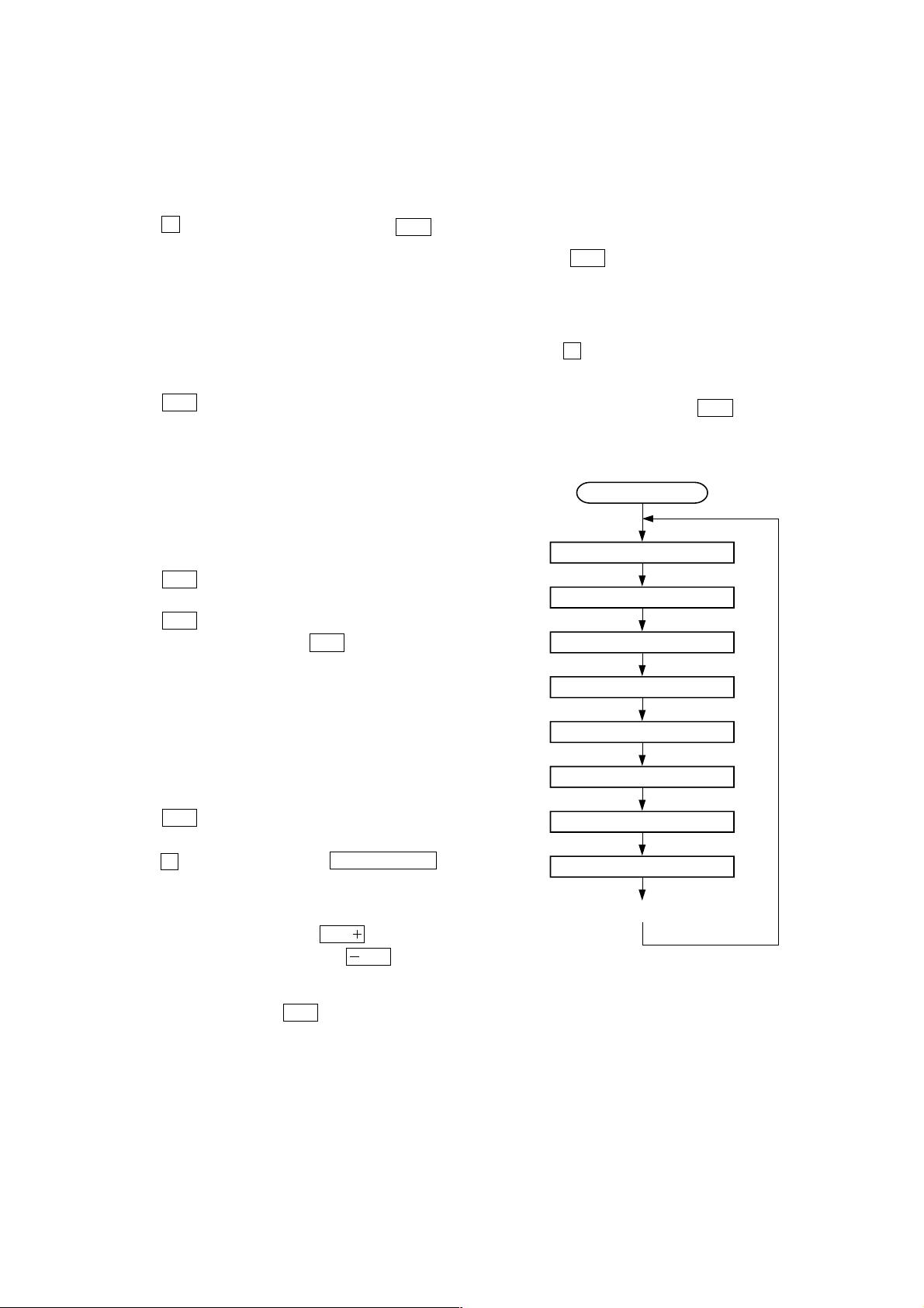
Aging mode sequence:
Start (from disc 1)
Disc chucking
TOC reading
Play first track for 2 seconds
Play last track for 2 seconds
button or disconnect the
?/1
[CD SERVICE MODE]
• This mode let you move the CD sled motor freely . Use this mode
when you want to clean the optical pick-up.
Procedure:
1. Press
2. Select CD function.
3. Press x , [AMP MENU] button, and
simultaneously.
4. The CD service mode is activated. The message “SERVICE
MODE” appears.
5. With the CD in stop status, press
optical pick-up to outside track, or press
to inside track. The message “SLED OUT” or “SLED IN”
appears.
6. To release this mode, press
button to turn the set ON.
?/1
?/1
OPEN/CLOSE
Z
button to move the
M
m
button.
button
button to move
EX-CHANGE open/close
Open the disc tray
Disc skip
Close the disk tray
Change the next disc.
17
HCD-GN800
>
• Display when an error occurred (CD Error Code Mode)
Procedure:
1. Press x button, [AMP MENU] button and [DISC 1] button
simultaneously to enter the error code display mode.
2. The fluorescent indicator tube displays the number of total error.
3. Each time
change as below
M
M
4. To clear the error record, operate the cold reset. (Refer to the
“MC COLD RESET”)
5. To release this mode, press the
power plug to turn the power OFF.
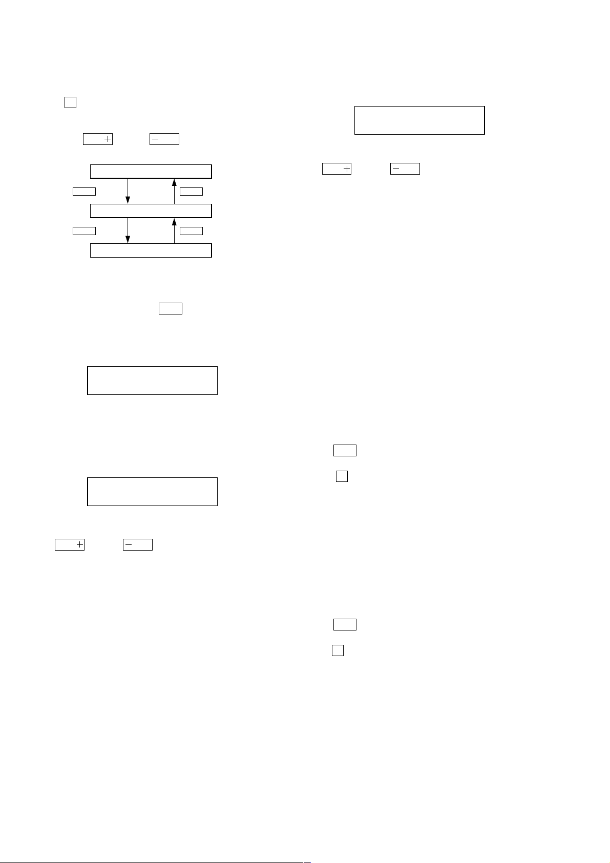
1) Display of total error
button or
M
Display of total error
+
Button
Display of Mechanical errors
+
Button
Display of no disc errors
Display
button is pressed, display
m
–
Button
m
–
Button
m
button or disconnect the
?/1
3) Display of no disc errors
Display
D*$$%%&&##00
D*: The number of mechanical error (“00” is latest one)
(Press
$$: Error type
01: Focus error
02: GFS error
03: Setup error
%%: Not used
&&:
00: No disc judgment without chucking retry.
01: No disc judgment after chucking retry.
##: The state when judged as no disc
01: Stop
02: Setup
03: TOC reading
04: Access
05: Playback
06: Pause
07: Manual search (Play)
08: Manual search (Pause)
button or
button to display next error)
.
EMC**EDC**
EMC**: The number of mechanical errors.
EDC**: The number of no disc errors after chucking the disc.
2) Display of mechanical errors
Display
M*$$%%&&##00
M*: The number of mechanical error (“00” is latest one)
(Press
$$: Not used
%%: Loading related error (Second figure is not used)
D: Stop by the problem other than mechanical problem while
E: Stop by the problem other than mechanical problem while
C: Stop by the problem other than mechanical problem while
F: Stop by the problem other than mechanical problem while
&&: Emerging error
01: Stop while chucking up.
02: Stop while chucking up.
03: Time-out of EX-CHANGE open.
05: Time-out of EX-CHANGE close.
##: Not used
button or
>
closing.
opening.
chucking up.
chucking down.
button to display next error)
.
[CD REPEAT 5 LIMIT OFF MODE]
• The number of repeat for CD playback is 5 times when the repeat
mode is “REPEAT ALL”. This mode enables CD to repeat
playback for limitless times.
Procedure:
1. Press
2. Select CD function.
3. Press x button, [REPEAT] button and [CD] button
simultaneously to enter the CD repeat 5 limit off mode and the
fluorescent indicator tube displays “LIMIT OFF”.
3. To release this mode, operate the cold reset. (Refer to the “MC
COLD RESET”)
button to turn the set ON.
?/1
[CD SHIP MODE (WITH MEMORY CLEAR)]
• This mode moves the optical pick-up to the position durable to
vibration and clears all data including preset data stored in the
RAM to initial conditions. Use this mode when returning the
set to the customer after repair.
Procedure:
1. Press
2. Select CD function.
3. Press x button, [AMP MENU] button and [GAME] button
simultaneously. The set will power off automatically.
4. After the “STANDBY” blinking display finish, a message
“LOCK” is displayed on the fluorescent indicator tube and the
CD ship mode is set.
button to turn the set ON.
?/1
18

HCD-GN800
[CD SHIP MODE (WITHOUT MEMORY CLEAR)]
• This mode moves the optical pick-up to the position durable to
vibration. Use this mode when returning the set to the customer
after repair.
Procedure:
1. Press
2. Select CD function.
3. Press [CD] button and
will power off automatically.
4. After the “STANDBY” blinking display finish, a message
“LOCK” is displayed on the fluorescent indicator tube and the
CD ship mode is set.
button to turn the set ON.
?/1
?/1
button simultaneously. The set
[CD POWER MANAGE]
• This mode let you switch on or off power supply to the BU
during TUNER function.
• When CD POWER is set to OFF, the power supply to the BU is
cut off during TUNER function. It will increase the time taken
to access CD when function change from TUNER to CD but it
will improve tuner reception.
• When CD POWER is set to ON, the power supply to the BU is
not cut off during TUNER function. It will reduce the time taken
to access CD when function change from TUNER to CD but it
will decrease tuner reception performance.
Procedure:
1. Press
2. Select CD function.
3. Press
4. Press x button and
power on automatically.
5. The message “CD POWER ON” or “CD POWER OFF” will
be displayed on the fluorescent indicator tube.
button to turn the set ON.
?/1
button to turn the set OFF.
?/1
?/1
button simultaneously . The set will
[CD TRAY LOCK MODE]
• This mode let you lock the disc trays. When this mode is
activated, the disc tray will not open when
button or [DISC SKIP/EX-CHANGE] button is pressed. The
message “LOCKED” will be displayed in the will be displayed
on the fluorescent indicator tube.
Procedure:
1. Press
2. Select CD function.
3. Press x button and
and hold down until “LOCKED” or “UNLOCKED” displayed
on the fluorescent indicator tube (around 5 seconds).
button to turn the set ON.
?/1
OPEN/CLOSE
Z
OPEN/CLOSE
Z
button simultaneously
[MD/VIDEO SWITCHING]
• This mode let you switch from MD to VIDEO and vice-versa.
Procedure:
1. Press
2. Select MD function.
3. Press [MD $VIDEO%] button and
The function will change to VIDEO. Press the same buttons
again to change from VIDEO to MD.
button to turn the set ON.
?/1
button simultaneously .
?/1
19
HCD-GN800
SECTION 5
MECHANICAL ADJUSTMENTS
Precaution
1. Clean the following parts with a denatured alcohol-moistened
swab:
record/playback heads pinch rollers
erase head rubber belts
capstan idlers
2. Demagnetize the record/playback head with a head
demagnetizer.
3. Do not use a magnetized screwdriver for the adjustments.
4. After the adjustments, apply suitable locking compound to the
parts adjusted.
5. The adjustments should be performed with the rated power
supply voltage unless otherwise noted.
Torque Measurement
Mode
FWD
FWD
back tension
REV
REV
back tension
FF/REW
FWD tension
REV tension
Torque meter
CQ-102C
CQ-102C
CQ-102RC
CQ-102RC
CQ-201B
CQ-403A
CQ-403R
Meter reading
3.06 N • m to 6.96 N • m
31 to 71 g • cm
(0.43 – 0.98 oz • inch)
0.19 N • m to 0.58 N • m
2 to 6 g • cm
(0.02 – 0.08 oz • inch)
3.06 N • m to 6.96 N • m
31 to 71 g • cm
(0.43 – 0.98 oz • inch)
0.19 N • m to 0.58 N • m
2 to 6 g • cm
(0.02 – 0.08 oz • inch)
6.96 N • m to 14.02 N • m
71 to 143 g • cm
(0.98 – 1.99 oz • inch)
9.80 N • m
100 g or more
(3.53 oz or more)
9.80 N • m
100 g or more
(3.53 oz or more)
SECTION 6
ELECTRICAL ADJUSTMENTS
DECK SECTION
1. Demagnetize the record/playback head with a head
demagnetizer.
2. Do not use a magnetized screwdriver for the adjustments.
3. After the adjustments, apply suitable locking compound to the
parts adjust.
4. The adjustments should be performed with the rated power
supply voltage unless otherwise noted.
5. The adjustments should be performed in the order given in this
service manual. (As a general rule, playback circuit adjustment
should be completed before performing recording circuit
adjustment.)
6. The adjustments should be performed for both L-CH and RCH.
7. Switches and controls should be set as follows unless otherwise
specified.
•Test Tape
Tape Signal Used for
P-4-A100 10 kHz, –10 dB Azimuth Adjustment
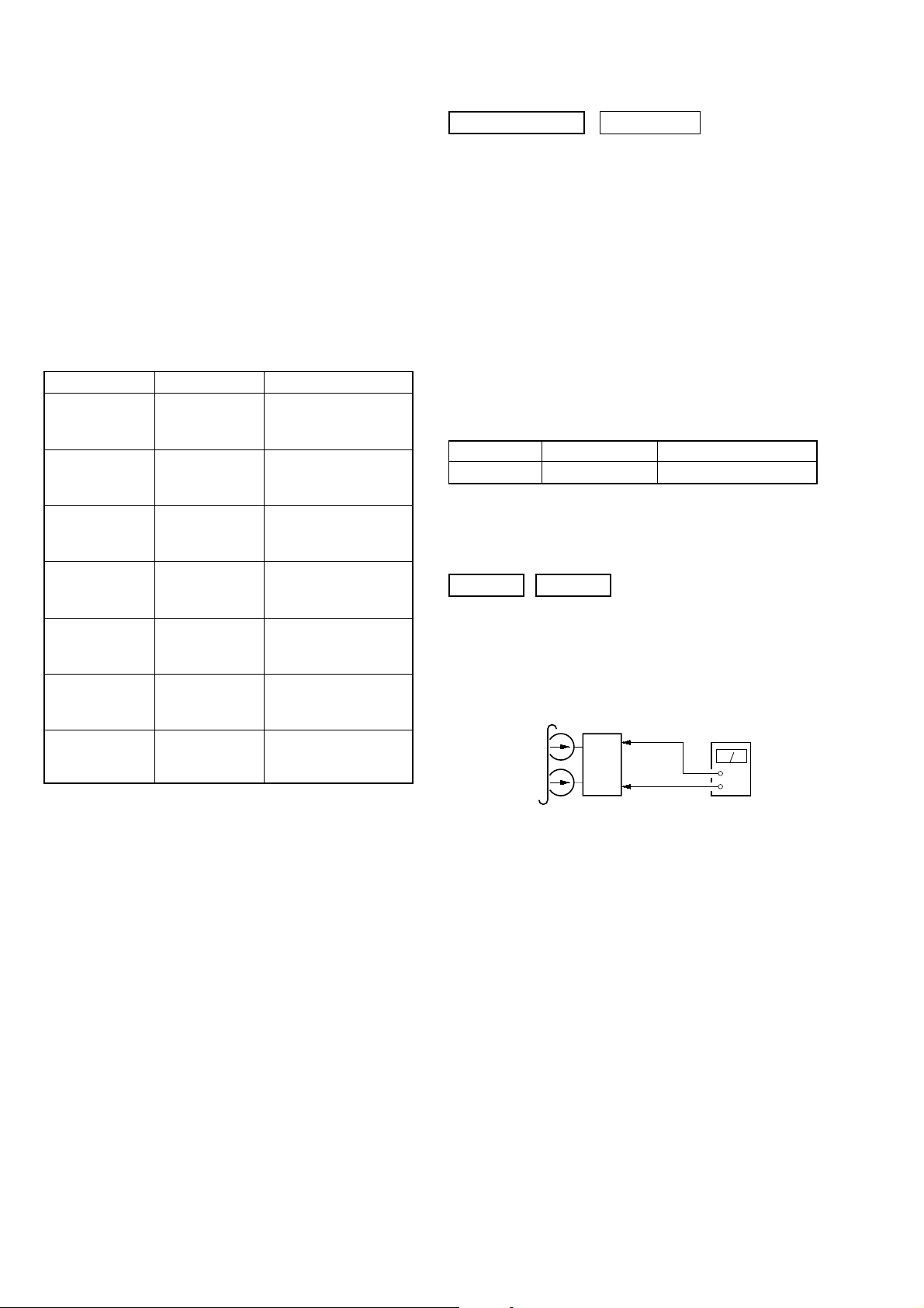
RECORD/PLAYBACK HEAD AZIMUTH ADJUSTMENT
DECK A DECK B
Note: Perform this adjustments for both decks
Procedure:
1. Mode: Playback
test tape
P-4-A100
(10 kHz, –10 dB)
0 dB=0.775 V
MAIN board
CN301
Pin
1
3
Pin
set
MAIN board
CN301
2
Pin
(L-CH)
(R-CH)
(GND)
level meter
+
–
20
HCD-GN800
e
attenuator
set
MAIN board
MD/VIDEO (AUDIO) IN (J750)
1) 315 Hz
2) 10 kHz
50 mV (–23.8 dB)
600
Ω
blank tape
CN-123
AF OSC
+
–
set
recorded
portion
MAIN board
CN301 Pin
2
(GND)
MAIN board
CN301
Pin
1
(L-CH)
Pin
3
(R-CH)
level meter
2. Turn the adjustment screw and check output peaks. If the peaks
do not match for L-CH and R-CH, turn the adjustment screw
so that outputs match within 1dB of peak.
Output
level
within
1dB
L-CH
peak
R-CH
peak
within
1dB
Screw
position
L-CH
peak
Screw
position
R-CH
peak
3. Mode: Playback
test tape
P-4-A100
(10 kHz, –10 dB)
L-CH
MAIN
board
CN301
set
R-CH
pin
L
R
pin
1
pin
3
2
oscilloscop
H
V
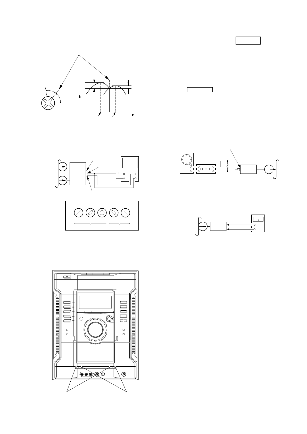
REC BIAS ADJUSTMENT DECK B
Procedure:
In the MC test mode, the “REC memory mode” is convenient for
this adjustment. In the “REC memory mode” , when the REC starts
the input signal FUNCTION is switched to VIDEO automatically.
When the REC stops, the tape returns near to the recording start
position.
1. Press MD (VIDEO) button to select VIDEO. (This step is not
necessary if the above test mode has already been set)
2. Insert a tape into deck B.
3. After press [REC PAUSE/START] b utton, press [REC PAUSE/
START] button, then recording start.
4. Mode: Record
5. Mode: Playback
waveform of oscilloscope
in phase 45°90°135°180
good
°
wrong
4. After the adjustments, apply suitable locking compound to the
pats adjusted.
Adjustment Location: Playback Head (Deck A).
Record/Playback/Erase Head (Deck B).
6. Confirm the playback signal recorded in step 3 becomes
adjustable level as follows.
If these levels are not adjustable level, adjust the RV304 (LCH) and RV354 (R-CH) on the MAIN board to repeat steps 4
and 5.
Adjustable level: Playback output of 315 Hz to playback output
of 10 kHz: ±1.0 dB
Adjustment Location: MAIN board
forward
reverse
21
HCD-GN800
+
–
CD board
TP4 (FE)
TP7 (DVC)
oscilloscope
REC LEVEL ADJUSTMENT DECK B
Procedure:
In the MC test mode, the “REC memory mode” is convenient for
this adjustment. In the “REC memory mode” , when the REC starts
the input signal FUNCTION is switched to VIDEO automatically.
When the REC stops, the tape returns near to the recording start
position.
1. Press MD (VIDEO) button to select VIDEO. (This step is not
necessary if the above test mode has already been set)
2. Insert a tape into deck B.
3. After press [REC PAUSE/START] b utton, press [REC PAUSE/
START] button, then recording start.
4. Mode: Record
MAIN board
MD/VIDEO (AUDIO) IN (J117)
AF OSC
5. Mode: Playback
315 Hz, 50 mV (–23.8 dB)
Ω
attenuator
600
blank tape
CS-123
set
CD SECTION
Note:
1. CD Block is basically designed to operate without adjustment. Therefore, check each item in order given.
2. Use YEDS-18 disc (3-702-101-01) unless otherwise indicated.
3. Use an oscilloscope with more than 10MΩ impedance.
4. Clean the object lens by an applicator with neutral detergent when the
signal level is low than specified value with the following checks.
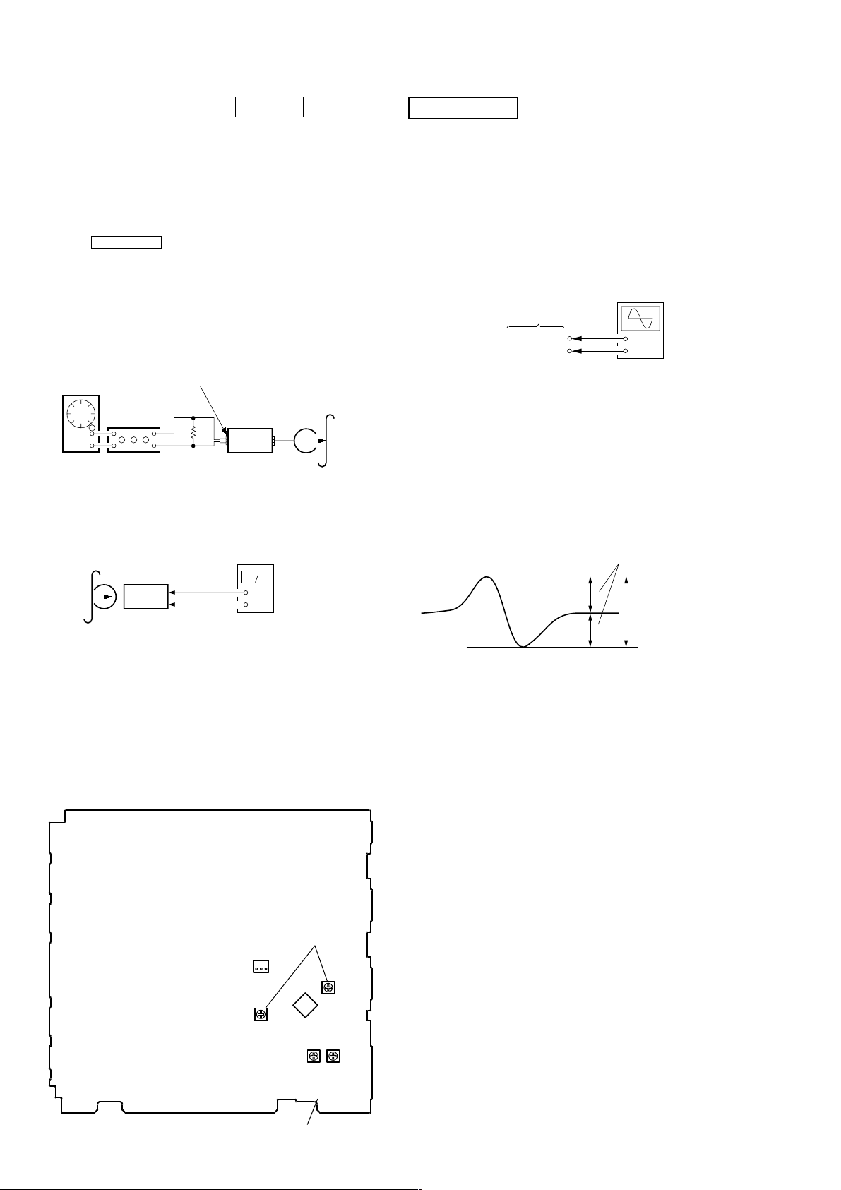
S-curve Check
Connection:
Procedure:
1. Connect an oscilloscope to test point TP4 (FE) and TP 7(DVC)
on the CD board.
2. Turn the power on.
3. Put the disc (YEDS-18) in and turned power switch on again
and actuate the focus search. (actuate the focus search when
disc table is moving in and out)
4. Check the oscilloscope waveform (S-curve) is symmetrical
between A and B. And confirm peak to peak le vel within 2.4 ± 1 Vp-p.
MAIN board
recorded
portion
CN301
1
Pin
Pin
3
set
MAIN board
CN301 Pin
(L-CH)
(R-CH)
2
level meter
+
–
(GND)
6. Confirm the play back signal recorded in step 3 becomes
adjustable level as follows.
If these levels are not adjustable level, adjust the RV301 (LCH) and RV351 (R-CH) on the MAIN board to repeat steps 4
and 5.
Adjustable level:
CN301 PB level: 47.2 to 53.0 mV (–24.3 to –23.3 dB)
Adjustment Location: MAIN board
– MAIN BOARD (Component Side) –
REC LEVEL
ADJUSTMENT
S-curve waveform
symmetry
A
B
Note: • Try to measure several times to make sure than the ratio of A : B
or B : A is more than 10 : 7.
• Take sweep time as long as possible and light up the
brightness to obtain best waveform.
within 2.4
±
1 Vp-p
Checking Location: CD board (SIDE B)
(See page 24.)
22
31
CN301
(R-CH)
RV351
REC BIAS ADJUSTMENT
IC301
RV304
(L-CH)
(R-CH)
RV301
(L-CH)
RV354
HCD-GN800
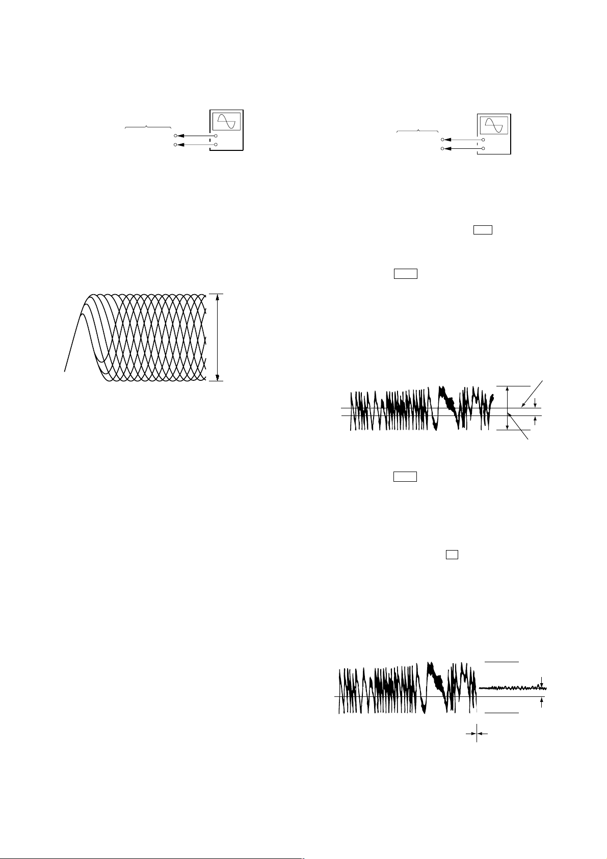
RFAC Level Check
Connection:
oscilloscope
CD board
TP5 (RFAC)
TP7 (DVC)
+
–
Procedure:
1. Connect an oscilloscope to test point TP5 (RFAC) and TP
7(DVC) on the CD board.
2. Turn the power on.
3. Put the disc (YEDS-18) in to playback the number five track.
4. Confirm that oscilloscope waveform is clear and check RF AC
signal level is correct or not.
Note: A clear RFAC signal waveform means that the shape “◊” can be
clearly distinguished at the center of the waveform.
RFAC signal waveform
VOLT/DIV: 200 mV
TIME/DIV: 500 ns
level: 0.9 ± 0.4 Vp-p
E-F Balance Check
Connection:
oscilloscope
CD board
TP2 (TE)
TP7 (DVC)
+
–
Procedure:
1. Connect an oscilloscpe to test point TP2 (TE) and TP7 (DVC)
on the CD board.
2. Turn the power on.
3. Select the function “CD”.
4. Press three buttons of
[ENTER], M , and
[SURRUUND MODE] simultaneously to set the CD service
mode.
5. Put the disc (YEDS-18) in to playback the number five track.
6. Press the . button. The message “TRAVERSE” is
displayed. (The tracking servo and the sledding servo are turned
OFF)
7. Check the level B of the oscilliscope's waveform and the A
(DC voltage) of the center of the Traverse waveform.
Confirm the following :
A/B x 100 = less than ± 22%
Traverse Wavef orm
Center of
the waveform
Checking Location: CD board (SIDE B)
(See page 24.)
B
0V
level: 1.0 ± 0.5 Vp-p
A (DC
8. Press the . button. The message “TRAVERSE” is
displayed. (The tracking servo and sledding servo are turned
ON)
Confirm the C (DC voltage) is almost equal to the A (DC
voltage) is step 5.
9. To exit from this mode, perform as follows.
1) Move the optical pick-up to the most inside track.
2) Press three buttons of x , [CLEAR], and [DISPLAY]
simultaneously. (cold reset)
Notes: • Always move the optical pick-up to most inside track when
0V
exiting from this mode. Otherwise, a disc will not be unloaded.
• Do not run the sled motor excessively, otherwise the gear can
be chipped.
Traverse Wavef orm
voltage)
C (DC
voltage)
Tracking servo
Sled servo
OFF
Tracking servo
Sled servo
ON
Checking Location: CD board (SIDE B) (See page 24.)
23
 Loading...