

Sony HCD-GN90D, HCD-GN100D Service Manual
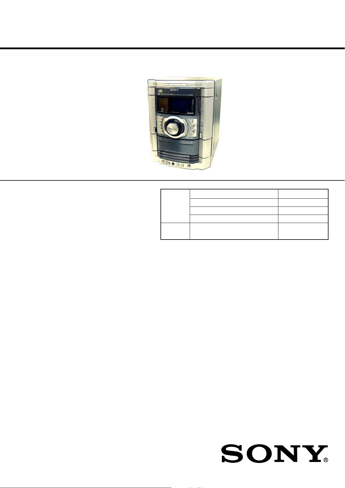
HCD-GN90D/GN100D
SERVICE MANUAL
Ver 1.0 2004. 07
• HCD-GN90D/GN100D are the Amplifier,
DVD player, tape deck and tuner
section in MHC-GN90D/GN100D.
This system incorporates Dolby* Digital, Dolby Pro Logic
(II) adaptive matrix surround decoder, and the DTS** Digital
Surround System.
* Manufactured under license from Dolby Laboratories.
“Dolby”, “Pro Logic”, and the double-D symbol are
trademarks of Dolby Laboratories.
** Manufactured under license from Digital Theater
Systems, Inc, “DTS” and “ DTS Digital Surround” are
registered trademarks of Digital Theater Systems. Inc.
DVD DVD Mechanism Type CDM74D2-DVBU62
Section Base Unit Name DVBU62
TAPE
Section
E Model
HCD-GN90D/GN100D
Australian Model
HCD-GN100D
Model Name Using Similar Mechanism NEW
Optical Pick-up Name DBU-3
Model Name Using Similar Mechanism NEW
SPECIFICATIONS
Amplifier section
MHC-GN100D
The following are measured at AC 120, 127, 220, 240V 50/60 Hz
DIN power output (rated)
Front speaker: 180 + 180 watts (6 ohms at 1 kHz, DIN)
Center speaker: 60 watts (8 ohms at 1 kHz, DIN)
Surround speaker: 60 + 60 watts (8 ohms at 1 kHz, DIN)
Continuous RMS power output (reference)
Front speaker: 235 + 235 watts
(6 ohms at 1 kHz, 10% THD)
Center speaker: 80 watts (8 ohms at 1 kHz, 10% THD)
Surround speaker: 80 + 80 watts
(8 ohms at 1 kHz, 10% THD)
MHC-GN90D
The following are measured at AC 120, 127, 220, 240V 50/60 Hz
DIN power output (rated)
Front speaker: 125 + 125 watts (6 ohms at 1 kHz, DIN)
Center speaker: 30 watts (8 ohms at 1 kHz, DIN)
Surround speaker: 30 + 30 watts (8 ohms at 1 kHz, DIN)
Continuous RMS power output (reference)
Front speaker: 170 + 170 watts
(6 ohms at 1 kHz, 10% THD)
Center speaker: 50 watts (8 ohms at 1 kHz, 10% THD)
Surround speaker: 50 + 50 watts
(8 ohms at 1 kHz, 10% THD)
Inputs
GAME INPUT (VIDEO): 1 Vp-p, 75 ohms
(phono jack)
GAME INPUT (AUDIO): Voltage 250 mV,
(phono jacks) impedance 47 kilohms
VIDEO/SAT (AUDIO) IN: voltage 450 mV/250 mV,
(phono jacks) impedance 47 kilohms
MIC: sensitivity 1 mV,
(phone jack) impedance 10 kilohms
Outputs
AUDIO OUT: Voltage 250 mV
(phono jacks) impedance 1 kilohms
VIDEO OUT: max. output level 1 Vp-p,
(phono jack) unbalanced, Sync.
negative load impedance
75 ohms
COMPONENT VIDEO
OUT: Y: 1 Vp-p, 75 ohms
PB/CB: 0.7 Vp-p, 75 ohms
PR/CR: 0.7 Vp-p, 75 ohms
– Continued on next page –
MiNi Hi-Fi COMPONENT SYSTEM
9-877-976-01
2004G02-1
© 2004.07
Sony Corporation
Home Audio Company
Published by Sony Engineering Corporation
HCD-GN90D/GN100D
S VIDEO OUT
(4-pin/mini-DIN jack): Y: 1 Vp-p, unbalanced,
Sync negative
C: 0.286 Vp-p load
impedance 75 ohms
PHONES: accepts headphones of
(stereo mini jack) 8 ohms or more
FRONT SPEAKER: Use only the supplied speaker
SUBWOOFER OUT: Voltage 250 mV
(phono jack) impedance 1 kilohms
SURROUND SPEAKER: Use only the supplied speakers
CENTER SPEAKER: Use only the supplied speaker
Disc player section
System Compact disc and digital
audio and video system
Laser Semiconductor laser
(DVD: λ = 650 nm,
CD: λ = 780 nm)
Emission duration: continuous
Frequency response DVD (PCM 48 kHz):
2 Hz – 22 kHz (±1dB)
CD: 2 Hz – 20 kHz (±0.5 dB)
Video color system format NTSC, PAL
(except Latin American models)
Tape deck section
Recording system 4-track 2-channel stereo
Frequency response 50 – 13,000 Hz (±3 dB),
using Sony TYPE I tape
Dimensions (w/h/d) (Approx.)
HCD-GN100D/GN90D 280 x 360 x 394.5 mm
Mass (Approx.)
HCD-GN100D 16.1 kg
HCD-GN90D 15.2 kg
Design and specifications are subject to change without notice.
Notes on chip component replacement
• Never reuse a disconnected chip component.
• Notice that the minus side of a tantalum capacitor may be
damaged by heat.
Flexible Circuit Board Repairing
• Keep the temperature of soldering iron around 270˚C
during repairing.
• Do not touch the soldering iron on the same conductor of the
circuit board (within 3 times).
• Be careful not to apply force on the conductor when soldering
or unsoldering.
CAUTION
Use of controls or adjustments or performance of procedures
other than those specified herein may result in hazardous
radiation exposure.
Tuner section
FM stereo, FM/AM superheterodyne tuner
FM tuner section
Tuning range 87.5 – 108.0 MHz (50 kHz step)
Antenna FM lead antenna
Antenna terminals 75 ohm unbalanced
Intermediate frequency 10.7 MHz
AM tuner section
Tuning range
Latin American models: 530 – 1,710 kHz
(with the interval set at 10 kHz)
531 – 1,710 kHz
(with the interval set at 9 kHz)
Saudi Arabian models: 531– 1,602 kHz
(with the interval set at 9 kHz)
Other models: 531 – 1,602 kHz
(with the interval set at 9 kHz)
530 – 1,710 kHz
(with the interval set at 10 kHz)
Antenna AM loop antenna
Antenna terminals External antenna terminal
Intermediate frequency 450 kHz
General
Power requirements
Australian model: 230 – 240 V AC, 50/60 Hz
Mexican model: 127 V AC, 60 Hz
Saudi Arabian models: 120 – 127 V, 220V or
230 – 240 V AC, 50/60 Hz
Adjustable with voltage selector.
Other models: 120 V, 220 V or
230 – 240 V AC, 50/60 Hz
Adjustable with voltage selector
Power consumption
MHC-GN100D 390 watts
MHC-GN90D 275 watts
This appliance is classified as
a CLASS 1 LASER product.
This label is located on the rear
exterior.
This following caution label is
located inside the apparatus.
SAFETY-RELATED COMPONENT WARNING!!
COMPONENTS IDENTIFIED BY MARK 0 OR DOTTED LINE WITH
MARK 0 ON THE SCHEMATIC DIAGRAMS AND IN THE PARTS
LIST ARE CRITICAL TO SAFE OPERATION. REPLACE THESE
COMPONENTS WITH SONY PARTS WHOSE PART NUMBERS
APPEAR AS SHOWN IN THIS MANUAL OR IN SUPPLEMENTS
PUBLISHED BY SONY.
2

TABLE OF CONTENTS
HCD-GN90D/GN100D
1. SERVICING NOTES ................................................ 4
2. GENERAL
Location of Controls ........................................................ 5
3. DISASSEMBLY
3-1. Disassembly Flow ........................................................... 7
3-2. Case ................................................................................. 8
3-3. Loading Panel Assy ......................................................... 8
3-4. Front Panel Assy .............................................................. 9
3-5. DVD Mechanism Deck (CDM74D2-DVBU62) ............. 9
3-6. Tape Mechanism Deck, Game Board .............................. 10
3-7. CD SW Board, Panel Board ............................................ 10
3-8. Switch Board ................................................................... 11
3-9. Tuner Pack ....................................................................... 11
3-10. Bracket Top, Bracket Sub ................................................ 12
3-11. Primary Board ................................................................. 12
3-12. DMB07 Board, Video Board ........................................... 13
3-13. Rear Panel ........................................................................ 13
3-14. Main Board, Power Board Assy ...................................... 14
3-15. Surround Board, PA Board .............................................. 14
3-16. Power Transformer (T601) .............................................. 15
3-17. Driver Board, SW Board ................................................. 15
3-18. RF Board, Optical Pick-Up (DBU-3) .............................. 16
3-19. Sensor Board ................................................................... 16
3-20. Motor (TB) Board ........................................................... 17
3-21. Motor (LD) Board ........................................................... 17
4. TEST MODE .............................................................. 18
5. MECHANICAL ADJUSTMENTS ....................... 27
6. ELECTRICAL ADJUSTMENTS
Deck section .................................................................... 27
Video Section .................................................................. 28
7. DIAGRAMS
7-1. Block Diagram – DVD Section (1/2) – .......................... 32
7-2. Block Diagram – DVD Section (2/2) – .......................... 33
7-3. Block Diagram – Tuner/Tape Section – ......................... 34
7-4. Block Diagram – Main Section – ................................... 35
7-5. Block Diagram – Display/Power Section – .................... 36
7-6. Block Diagram – Amp Section – .................................... 37
7-7. Printed Wiring Board – RF Board – ............................... 38
7-8. Schematic Diagram – RF Board – .................................. 39
7-9. Printed Wiring Board – DVD Mechanism Board – ....... 40
7-10. Schematic Diagram – DVD Mechanism Board – .......... 41
7-11. Printed Wiring Board – DMB07 Board (Side A) – ........ 42
7-12. Printed Wiring Board – DMB07 Board (Side B) – ........ 43
7-13. Schematic Diagram – DMB07 Board (1/6) – ................. 44
7-14. Schematic Diagram – DMB07 Board (2/6) – ................. 45
7-15. Schematic Diagram – DMB07 Board (3/6) – ................. 46
7-16. Schematic Diagram – DMB07 Board (4/6) – ................. 47
7-17. Schematic Diagram – DMB07 Board (5/6) – ................. 48
7-18. Schematic Diagram – DMB07 Board (6/6) – ................. 49
7-19. Printed Wiring Board – Video Board – .......................... 50
7-20. Schematic Diagram – Video Board – ............................. 51
7-21. Printed Wiring Boards – Main Board – .......................... 52
7-22. Schematic Diagram – Main Board (1/4) – ..................... 53
7-23. Schematic Diagram – Main Board (2/4) – ..................... 54
7-24. Schematic Diagram – Main Board (3/4) – ..................... 55
7-25. Schematic Diagram – Main Board (4/4) – ..................... 56
7-26. Printed Wiring Board – Panel Board – ........................... 57
7-27. Schematic Diagram – Panel Board (1/2) – .................... 58
7-28. Schematic Diagram – Panel Board (2/2) – .................... 59
7-29. Printed Wiring Boards
– Game, CD SW Board – ................................................ 60
7-30. Schematic Diagram
– Game, CD SW Board – ................................................ 61
7-31. Printed Wiring Board – PA Board – ............................... 62
7-32. Schematic Diagram – PA Board – .................................. 63
7-33. Printed Wiring Board – Surround Board – ..................... 64
7-34. Schematic Diagram – Surround Board – ........................ 65
7-35. Printed Wiring Boards – Primary Board – ..................... 66
7-36. Schematic Diagram – Primary Board – .......................... 67
7-37. Circuit Board Location .................................................... 68
7-38. IC Block Diagram ........................................................... 69
8. EXPLODED VIEWS
8-1. Case, Rear Panel Section ................................................. 85
8-2. Front Panel Section ......................................................... 86
8-3. Chassis Section ................................................................ 87
8-4. DVD Mechanism Deck Section-1
(CDM74D2-DVBU62) ................................................... 88
8-5. DVD Mechanism Deck Section-2
(CDM74D2-DVBU62) ................................................... 89
9. ELECTRICAL PARTS LIST ................................ 90
3
HCD-GN90D/GN100D
SECTION 1
SERVICING NOTES
NOTES ON HANDLING THE OPTICAL PICK-UP BLOCK
OR BASE UNIT
The laser diode in the optical pick-up block may suffer electrostatic
break-down because of the potential difference generated by the
charged electrostatic load, etc. on clothing and the human body.
During repair, pay attention to electrostatic break-down and also
use the procedure in the printed matter which is included in the
repair parts.
The flexible board is easily damaged and should be handled with
care.
NOTES ON LASER DIODE EMISSION CHECK
The laser beam on this model is concentrated so as to be focused on
the disc reflective surface by the objective lens in the optical pickup block. Therefore, when checking the laser diode emission, observe
from more than 30 cm away from the objective lens.
LASER DIODE AND FOCUS SEARCH OPERATION CHECK
Carry out the “S curve check” in “CD section adjustment” and check
that the S curve waveform is output several times.
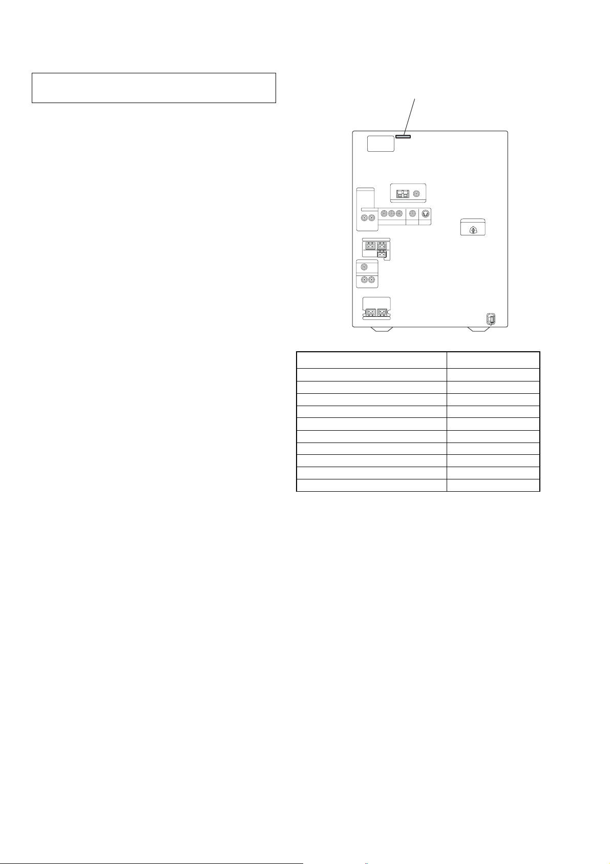
• MODEL IDENTIFICATION
– Back Panel –
MODEL PART No.
GN100D : SP, MY models 4-254-995-1[]
GN100D : EA model 4-254-995-2[]
GN100D : E3, E15 models 4-254-995-3[]
GN100D : PH model 4-254-995-4[]
GN100D : AUS model 4-254-995-5[]
GN100D : MX model 4-254-995-6[]
GN90D : EA model 4-254-997-0[]
GN90D : SP models 4-254-997-1[]
GN90D : E15 model 4-254-997-2[]
GN90D : PH model 4-254-997-3[]
PAR T N o.
•Abbreviation
E3 : 240 V AC Area in E model
E15 : Iran model
AUS : Australian model
MX : Mexican model
PH : Philippine model
SP : Singapore model
MY : Malaysia model
EA : Saudi Arabia model
4

SECTION 2
41 3 65
GENERAL
LOCATING THE CONTROLS
List of button locations and reference pages
Unit
HCD-GN90D/GN100D
This section is extracted
from instruction manual.
ALPHABE TICAL ORDER
A – D
ALBUM qh
AMP MENU ra
CD SYNC qf
Deck A wl
Deck B w;
DIRECTION qa
DISC 1 ~ 3 3
Disc tray rg
DISPLAY rd
Display 5
DOLBY PL II ek
DVD el
E – L
ECHO LEVEL wg
EFFECT ON/OFF r;
ENTER wa
EQ EDIT 8
EX-CHANGE/DISC SKIP 4
FM MODE q;
GAME es
GAME INPUT (jacks) wk
GAME MIXING ej
GROOVE ea
ILLUMINATION e;
M – R
MIC (jack) wj
MIC LEVEL wh
MULTI JOG ws
P FILE MEMORY 7
PHONES (jack) wf
PLAY MODE 9
Power illuminator 2
REC PAUSE/START qg
REPEAT q;
S – Z
SLEEP rs
SOUND FIELD rf
TAPE A/B eg
TUNER/BAND eh
TUNER MEMORY qa
TUNING MODE 9
VIDEO/SAT ed
VOLUME wd
rg
rf
rd
rs
ra
r;
el
ek
ej
eh
eg
ef
ed
es
ea
e;
wl
2
SYMBOLS
?/1 (power) 1
Z OPEN/CLOSE 6
nN (play) qs
–. >+ (go backward/
forward) qd
–m M+ (rewind/fast forward)
X (pause) ql
x (stop) qk
Z A (Eject A) ef
Z B (Eject B) qj
7
8
9
q;
qa
qs
qd
qf
qg
qh
qj
qk
ql
w;
wa
ws
wd
qh
wk
wj
wh
wgwf
5

HCD-GN90D/GN100D
Remote control
This section is extracted
from instruction manual.
ALPHABE TICAL ORDER
A – E
ALBUM + 7
ALBUM – qa
ANGLE qk
AUDIO qk
BAND wg
CLEAR wl
CLOCK/TIMER SELECT e;
CLOCK/TIMER SET e;
DISC SKIP wf
DISPLAY wa
DVD DISPLAY wh
DVD MENU 7
DVD SETUP ws
DVD TOP MENU qa
ENTER wj
F – Z
FM MODE 5
FUNCTION +/– q;
KARAOKE/MPX qf
KEY CONTROL #/29
Numeric Buttons qd
PLAY MODE 4
REPEAT 5
SLEEP qh
SLOW / w;
SOUND FIELD +/– wd
SUBTITLE qk
TUNER MEMORY 3
TUNING MODE 4
TUNING +/– wk
TV CH +/– qg
TV/VIDEO ea
TV VOL +/– 2
TV &/1 qj
VOLUME +/– 8
SYMBOLS
?/1 (power) 1
x (stop) 6
X (pause) 6
nN (play) 6
–. (go backward) wk
>+ (go forward) wk
m (rewind) w;
M (fast forward) w;
M/m/</, wj
> 10 qs
O RETURN ql
ea
e;
wl
wk
wj
wh
wg
wf
qj
qh
+–+
–
qk
qf
+–+
–
qd
+–
–
V
v
+
–
O
y
y
mM.>
XbB
x
+
bB
+
–
+
–
ql
w;
wa
ws
qs
qa
0
y
mM.>
XbB x
+–
bB
+
–
O
y
+
–
+–
V
v
+
–
1
2qg
3
4
5
6
7
8
9
wd
6
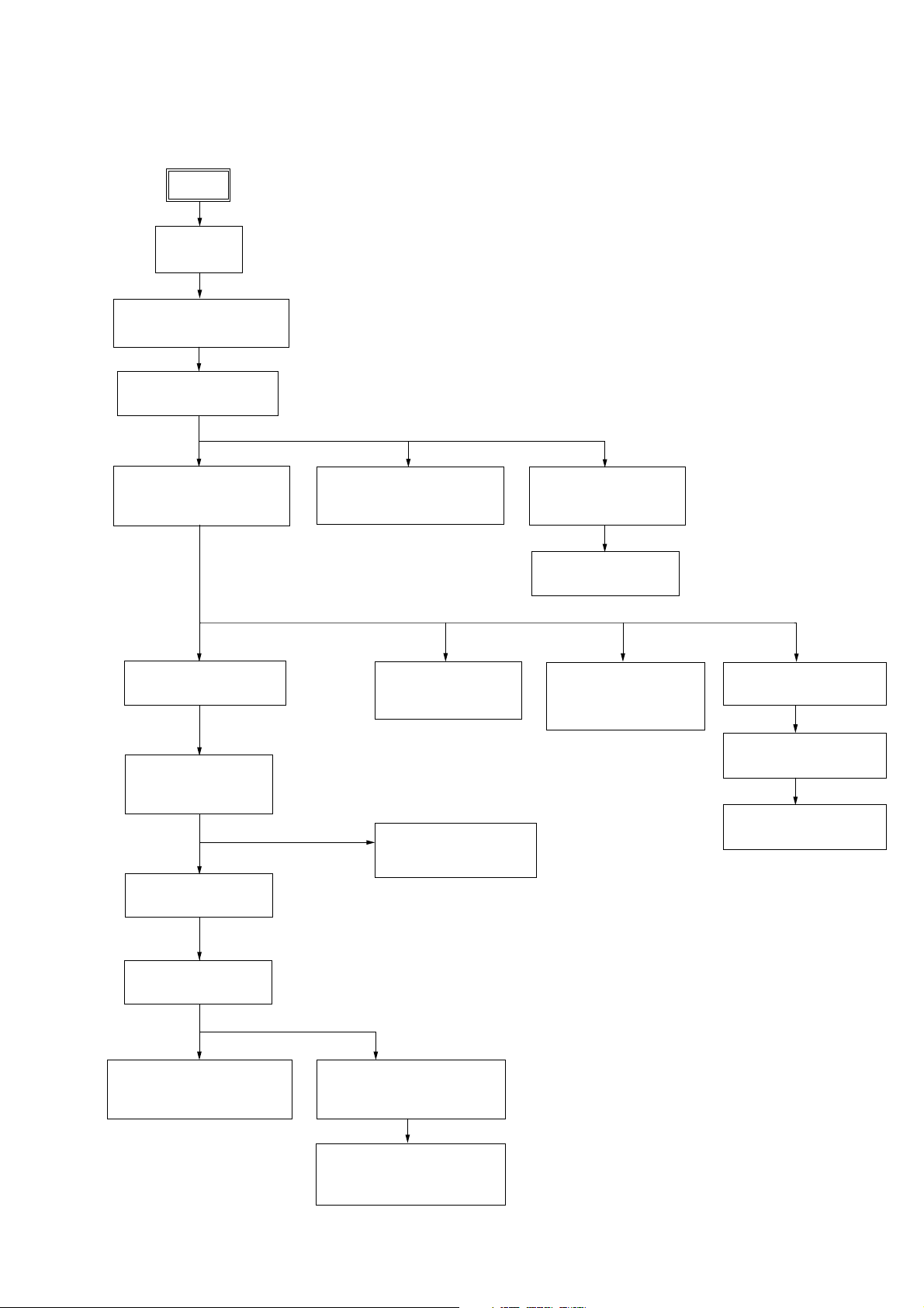
• This set can be disassembled in the order shown below.
3-1. DISASSEMBLY FLOW
SET
3-2.CASE
(Page 8)
3-3.LOADING PANEL ASSY
(Page 8)
3-4.FRONT PANEL ASSY
(Page 9)
HCD-GN90D/GN100D
SECTION 3
DISASSEMBLY
3-5.DVD MECHANISM DECK
(CDM74D2-DVBU62)
(Page 9)
3-9.TUNER PACK
(Page 11)
3-10.BRACKET TOP,
BRACKET SUB
(Page 12)
3-11.PRIMARY BOARD
(Page 12)
3-6.TAPE MECHANISM DECK,
GAME BOARD
(Page 10)
3-17.DRIVER BOARD,
SW BOARD
(Page 15)
3-12.DMB07 BOARD,
VIDEO BOARD
(Page 13)
3-7.CD SW BOARD,
PANEL BOARD
(Page 10)
3-8.SWITCH BOARD
(Page 11)
3-18. RF BOARD,
OPTICAL PICK-UP
(DBU-3)
(Page 16)
3-19.SENSOR BOARD
(Page 16)
3-20.MOTOR (TB) BOARD
(Page 17)
3-21.MOTOR (LD) BOARD
(Page 17)
3-13.REAR PANEL
(Page 13)
3-14.POWER TRANSFORMER
(T601)
(Page 15)
POWER BOARD ASSY
3-14.MAIN BOARD
(Page 14)
3-15.SURROUND BOARD,
PA BOARD
(Page 14)
7

HCD-GN90D/GN100D
)
Note: Follow the disassembly procedure in the numerical order given.
3-2. CASE
7
case
2
screw
(case 3 TP2) (M3 x 12)
1
two screws
(case 3 TP2)
(M3 x 8)
6
3
five screws
(+BVTT3 x 6)
5
4
two screws
(+BVTT3 x 6)
3-3. LOADING PANEL ASSY
DVD mechanismdeck (CDM74D2-DVBU62)
1
Turn the pulley to the arrow direction.
Pulley
Front side
4
loading panel assy
3
2
screw (case 3 TP2
(M3 x 12)
two screws
1
(case 3 TP2) (M3 x 8)
Pull out disc tray
2
8
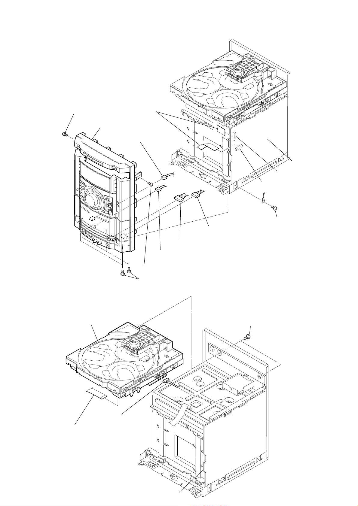
3-4. FRONT PANEL ASSY
)
3
screw (BVTP3 x 10)
9
front panel assy
1
two wires
(flat type)
8
from CN802 on
GAME board
HCD-GN90D/GN100D
MAIN board
CN508
CN509
7
from deck A head
3
screw (BVTP3 x 10)
2
five screws (BVTP3 x 10)
3-5. DVD MECHANISM DECK (CDM74D2-DVBU62)
4
DVD mechanism deck
5
from deck B head
6
from CN801 on GAME board
4
1
two screws (BVTP3 x 10
screw (BVTP3 x 10)
2
wire (flat type) (29 core)
3
CN701
MAIN board
9
HCD-GN90D/GN100D
)
3-6. TAPE MECHANISM DECK, GAME BOARD
2
tape mechanism deck
1
five screws
(+BVTP2.6 x 8)
3
three screws
(+BVTP2.6 x 8)
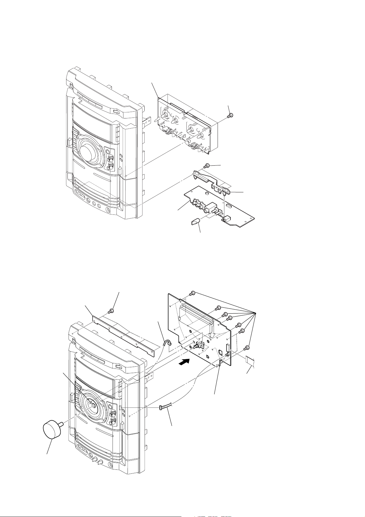
3-7. CD SW BOARD, PANEL BOARD
2
CD SW board
6
claw
1
five screws
(+BVTP2.6 x 8)
8
CN907
6
GAME board
7
5
knob (MIC)
4
bracket (MIC
nineteen screws
5
(+BVTP2.6 x 8)
9
wire (flat type) (19 core)
from CN902
10
3
knob (VOL)
4
CN903
0
PANEL board

3-8. SWITCH BOARD
)
HCD-GN90D/GN100D
2
two screws
(+BVTP2.6 x 8
3
SWITCH board
3-9. TUNER PACK
3
tuner pack
1
wire (flat type)
(11 core)
1
two knobs (AMS)
2
two screws
(+BVTT3 x 6)
11

HCD-GN90D/GN100D
)
3-10. BRACKET TOP, BRACKET SUB
4
bracket, top
2
two screws
(BVTP3 x 10)
3
8
two screws
(BVTP3 x 6)
7
wire (flat type)
(21 core)
5
wire (flat type)
(7 core)
6
connector
(CN1200)
(CN516)
(CN517)
1
four screws
(BVTT3 x 6 (S)
3-11. PRIMARY BOARD
3
(CN1001)
2
(CN1002)
connector
4
connector
(CN1000)
connector
9
bracket, sub
5
connector
(CN101)
7
PRIMARY board
1
two screws
(+BVTT3 x 6 (S))
12
6
connector
(CN201)

3-12. DMB07 BOARD, VIDEO BOARD
HCD-GN90D/GN100D
bracket, top
3-13. REAR PANEL
(CN501)
(CN105)
(CN1202)
(CN101)
1
wire (flat type) (29 core)
5
(DVD)
4
four screws
(BVTP3 x 10)
8
VIDEO board
7
(BVTP3 x 10)
3
wire (flat type) (17 core)
6
DMB07 board
2
wire (flat type) (7 core)
Heat sink
three screws
3
rear panel
with fan
MAIN board
CN503
4
Connector
2
screw
(+BVTT3 x 6)
1
eleven screws
(+BVTP3 x 10)
13

HCD-GN90D/GN100D
3-14. MAIN BOARD, POWER BOARD ASSY
4
two screws
(+BVTT3 x 6 (S))
2
connector
4p (CN703)
1
connector
6p (CN604)
3
two screws
(+BVTT3 x 6 (S))
5
screw
(+BVTT3 x 6 (S))
7
POWER board assy
6
screw
(+BVTP3 x 10)
3-15. SURROUND BOARD, PA BOARD
3
SURROUND board
9
MAIN board
1
two screws
(transistor)
2
two screws
(+BVTP3 x 10)
8
heat sink
9
PA board
8
two screws
(+BVTP3 x 10)
14
4
screw
(+BVTP3 x 10)
5
bracket
6
two screws
(transistor)
7
two screws
(+BVTP3 x 10)

3-16. POWER TRANSFORMER (T601)
1
connector
6p (CN604)
2
connector
4p (CN703)
3
six
screws
HCD-GN90D/GN100D
4
power transformer (T601)
3-17. DRIVER BOARD, SW BOARD
1
two
screws
(+BTTP (M2.6))
4
DRIVER
2
wire (flat type) 5p
(CN702)
board
3
connector
4p (CN703)
5
(+BTTP (M2.6))
screw
6
SW board
15
HCD-GN90D/GN100D
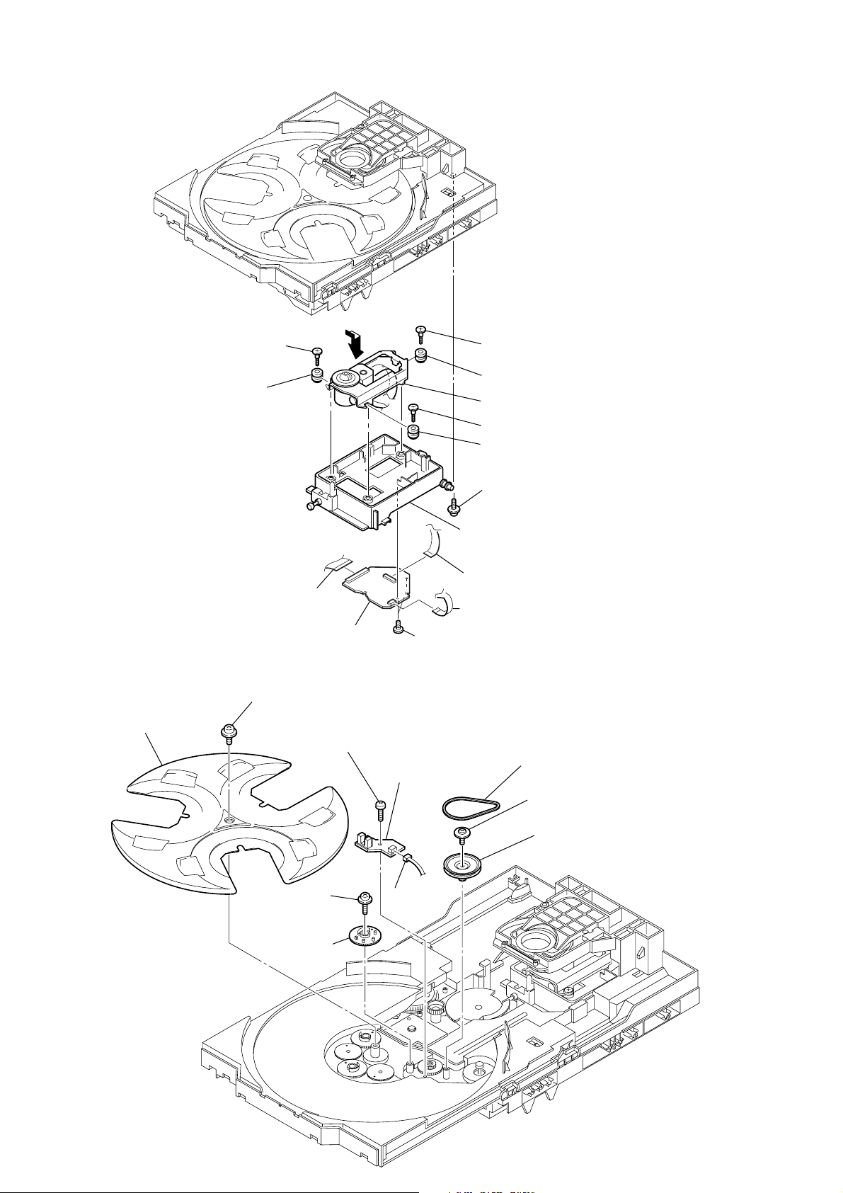
3-18. RF BOARD, OPTICAL PICK-UP (DBU-3)
8
Step
screw (M)
qa
Insulator (RB)
7
9
Step
screw (M)
qs
Insulator
qf
Optical pick-up (DBU-3)
0
Step
screw (M)
qd
Insulator (RB)
3-19. SENSOR BOARD
2
t
ray
1
Flat type wire
(CN002)
5
1
floating
(+PTPWH M2.6)
6
floating
(+PTPWH M2.6)
screw
8
s
(+BTTP (M2.6))
screw
RF board
crew
qg
3
4
2
Tw o screws (+BTTP 2.6)
0
SENSOR board
9
connector
(
CN731)
6
Floating
Holder (DBU) assy
Flat type wire
Flat type wire
screw (PTPWH M2.6)
(CN001)
(CN003)
3
b
elt (table)
4
floating
(+PTPWH M2.6)
5
p
screw
ulley (table)
16
7
g
ear (geneva)

3-20. MOTOR (TB) BOARD
2
stopper
4
1
stopper
7
t
able motor assy (M741)
HCD-GN90D/GN100D
3-21. MOTOR (LD) BOARD
4
Remove the two solderings of motor.
5
l
oading motor assy (M751)
3
8
MOTOR (TB) board
6
Remove the two solderings of motor.
5
two
screws
(+BTTP (M2.6))
2
two
screws
(+BTTP (M2.6))
3
MOTOR (LD) board
wire (flat type) 5 core (CN742)
1
b
elt (loading)
17

HCD-GN90D/GN100D
SECTION 4
TEST MODE
[GC TEST MODE]
• This mode is used to check the fluorescent indicator tube, LED,
model, destination, software version, volume, key, jog, encoder
and VACS level.
Procedure:
1. Press
2. All LEDs and segments in fluorescent indicator tube are lighted up.
3. When you want to enter the software version display mode,
4. Each time
5. When
x
button, [ENTER] button and [DISC2] button
simultaneously.
[DISC1] button. The model and destination are displayed.
press
[DISC1] button is pressed, the display changes from
MC version, GC version, CD version, ST version, TC version,
TA version, TM version in this order, and returns to the MC
version display.
[DISC3] button is pressed while the version numbers are
being displayed except model and destination, the date of the
software creation appear. When
the display returns to the software version display. When
[DISC3] button is pressed again,
[DISC1] button is pressed while the date of the software creation
is being displayed, the date of the software creation is displayed
in the same order of software version display.
6. Press
7. In the key check mode, the fluorescent indicator tube displays
8. When
9. When
10. To release from this mode, press three buttons in the same
[DISC2] button, the key check mode is activated.
“K0 J0 V0 E0”.
Each time a button is pressed, “K” value increases. However,
once a button has been pressed, it is no longer taken into account.
“J” value increases in the manner of 0,1, 2, 3 ... if
knob is turned clockwise, or it decreases in the manner of 0, 9,
[MULTI JOG] knob is turned counter-clockwise.
8,7 ... if
“V” value increases in the manner of 0, 1, 2, 3 ... if
knob is turned clockwise, or it decreases in the manner of 0, 9,
8,7 ... if
[VOLUME] knob is turned counter-clockwise.
“E” value increases in the manner of 0, 1, 2, 3 ... if
knob is turned clockwise, or it decreases in the manner of 0, 9,
8,7 ... if
.>
knob is turned counter-clockwise.
[MULTI JOG]
[VOLUME]
.>
[DISC3] button is pressed after all LEDs and segments
in fluorescent indicator tube light up, the fluorescent indicator
tube displays “VACS A+B APCC”. A is VACS level which is
trigger by signal level, B is VACS level which is trigger by
temperature and CC is VACS level which is trigger by APVACS
(Abuse Protection VACS).
[EX-CHANGE/DISC SKIP] button is pressed after all
LEDs and segments in fluorescent indicator tube light up,
alternate segments in fluorescent indicator tube would light up.
If you press
half of alternate segments in fluorescent indicator tube would
light up. Pressing
would cause all segments lights up.
manner as step 1, or disconnect the power cord.
[EX-CHANGE/DISC SKIP] button again, another
[EX-CHANGE/DISC SKIP] button again
[MC TEST MODE]
• This mode is used to check operations of the respective sections
of Amplifier, Tuner, and Tape.
Check of Amplifier
*
1. Press [EQ EDIT] button repeatedly until a message “GEQ MAX”
appears on the fluorescent indicator tube. GEQ increases to its
maximum.
2. Press [EQ EDIT] button repeatedly until a message “GEQ MIN”
appears on the fluorescent indicator tube. GEQ increases to its
minimum.
3. Press [EQ EDIT] button repeatedly until a message “GEQ FLAT”
appears on the fluorescent indicator tube. GEQ set to flat.
4. When the [VOLUME] knob is turned clockwise even slightly,
the sound volume increases to its maximum and a message
“VOLUME MAX” appears on the fluorescent indicator tube.
5. When the [VOLUME] knob is turned counter-clockwise even
slightly, the sound volume decreases to its minimum and a
message “VOLUME MIN” appears on the fluorescent indicator
tube.
Tape function
*
1. When a tape is inserted in Deck B and recording is started, the
function is changed to VIDEO automatically. When [CD SYNC]
button is pressed during recording in function, ALC (Automatic
Logic Control) is turned on.
2. During recording, turn
stop the recording and the function is changed to TAPE B and
rewind the tape in Deck B until the recording start position and
playback of the tape B is started. If the [REC PAUSE/ START]
button is pressed for a pause and pressed again to resume
recording during recording time, when the tape is rewind, the
tape will be rewind until the position where the pause is applied.
AMS Test Mode
*
1. Select the function “TAPE A” or “TAPE B”.
2. Select Loop or Relay direction mode by pressing the
[DIRECTION] button. Insert a test tape AMS-110A or AMS-120
to selected tape deck.
3. Press the [AMP MENU] button to enter the AMS test mode.
4. After the test tape is rewind to the beginning of the tape, the
AMS+ is checked, and the mechanism is shut off after detecting
the AMS signal twice.
5. Then the AMS- is checked and the mechanism is shut off after
detecting the AMS signal twice.
6. When the check is complete, a message of either OK or NG
appears on the fluorescent indicator tube.
To release from MC Test mode
*
1. To release from this mode, press
2. The cold reset is enforced at the same time.
m M
knob counterclockwise will
button.
?/1
[COLD RESET]
• The cold reset clears all data including preset data stored in the
RAM to initial conditions.
Procedure:
x
1. Press
simultaneously.
2. The fluorescent indicator tube becomes blank for a while, and
the set is reset.
button, [ENTER] button, and
?/1
button
Procedure:
•To enter MC Test Mode
1. Press
2. The DVD ring indicators and TAPE A and B indicators flash on
x
button, [ENTER] button and [DISC3] button
simultaneously.
the fluorescent indicator tube. The function is changed to
VIDEO.
18

HCD-GN90D/GN100D
[VACS ON/OFF]
• This mode is used to switch ON and OFF the VACS (Variable
Attenuation Control System).
Procedure:
1. Press
button to turn the set ON.
?/1
2. Press [ENTER] button and [GAME MIXING] button simultaneously.
The message “VACS OFF” or “VACS ON” appears on the
fluorescent indicator tube.
[TUNER STEP CHANGE]
• The step interval of AM channels can be toggled between 9 kHz
and 10 kHz.
Procedure:
1. Press
button to turn the set ON.
?/1
2. Press [TUNER/BAND] button to select the “AM”.
3. Press
4. Press [ENTER] button and
button to turn the set OFF.
?/1
button simultaneously. The set
?/1
will power ON automatically. The message “AM 9k STEP” or
“AM 10k STEP” appears on the fluorescent indicator tube and
thus the channel step is changed.
[REPEAT 5 LIMIT OFF MODE]
• The number of repeat for disc playback is 5 times when the
repeat mode is “REPEAT ALL”. This mode enables the disc to
repeat playback for limitless times.
Procedure:
1. Press
2. Select DVD function.
3. Press
simultaneously to enter the repeat 5 limit off mode and the
fluorescent indicator tube displays “LIMIT OFF”.
•To release from this mode, operate the cold reset. (Refer to the
“MC COLD RESET”)
button to turn the set ON.
?/1
x
button, [EQ EDIT] button and [DVD] button
[DVD POWER MANAGE]
• This mode let you switch on or off power supply to the ZIVA
during TUNER function.
• When DVD POWER is set to OFF, the power supply to the ZIVA
is cut off during TUNER function. It will increase the time taken
to access disc when function change from TUNER to DVD but it
will improve tuner reception performance.
• When DVD POWER is set to ON, the power supply to the ZIVA
is not cut off during TUNER function. It will reduce the time
taken to access disc when function change from TUNER to DVD
but it will decrease tuner reception performance.
Procedure:
1. Press
button to turn the set ON.
?/1
2. Select DVD function.
3. Press
4. Press
button to turn the set OFF.
?/1
x
button and
?/1
button simultaneously. The set will
power on automatically.
5. The message “DVD POWER ON” or “DVD POWER OFF”
will be displayed on the fluorescent indicator tube.
[DVD TRAY LOCK MODE]
• This mode let you lock the disc tray. When this mode is
activated, the disc tray will not open when [OPEN/CLOSE]
button or [EX-CHANGE/DISC SKIP] button is pressed. The
message “LOCKED” will be displayed in on the fluorescent
indicator tube.
Procedure:
1. Press
2. Select DVD function.
3. Press
and hold down until “LOCKED” or “UNLOCKED” displayed
on the fluorescent indicator tube (around 5 seconds).
button to turn the set ON.
?/1
x
button and [OPEN/CLOSE] button simultaneously
[DVD SHIP MODE (WITH MEMORY CLEAR)]
• This mode moves the optical pick-up to the position durable to
vibration and clears all data including preset data stored in the
RAM to initial conditions. Use this mode when returning the
set to the customer after repair.
Procedure:
1. Press
button to turn the set ON.
?/1
2. Select DVD function.
3. Press
x
button, [ENTER] button and [GAME] button
simultaneously. The set will power off automatically.
4. After the “STANDBY” blinking display finish, a message
“LOCK” is displayed on the fluorescent indicator tube and the
DVD ship mode is set.
[DVD SHIP MODE (WITHOUT MEMORY CLEAR)]
• This mode moves the optical pick-up to the position durable to
vibration.
Procedure:
1. Press
2. Select DVD function.
3. Press [DVD] button and [POWER] button simultaneously. The
set will power off automatically.
4. After the “STANDBY” blinking display finish, a message
“LOCK” is displayed on the fluorescent indicator tube and the
DVD ship mode is set.
button to turn the set ON.
?/1
[VIDEO/SAT SWITCHING]
• This mode let you switch from VIDEO to SAT and vice-versa.
Procedure:
1. Press
button to turn the set ON.
?/1
2. Select VIDEO function.
3. Press [VIDEO/SAT] button and
button simultaneously. The
?/1
function will change to SAT. Press the same buttons again to
change from SAT to VIDEO.
[DVD COLOR SYSTEM SWITCHING]
• This mode let you change the color system of the video output
from PAL to NTSC or vice-versa.
Procedure:
1. Press
2. Select DVD function.
3. Press
4. Press [PAUSE] button and
will power on automatically.
5. The message “COLOR PAL” or “COLOR NTSC” will be
displayed on the fluorescent indicator tube.
button to turn the set ON.
?/1
button to turn the set OFF.
?/1
button simultaneously. The set
?/1
19

HCD-GN90D/GN100D
[DVD PROGRESSIVE]
• This mode let you change the video signal format from PROGRESSIVE format to INTERLACE format if you accidentally
change the COMPONENT OUT settings in DVD SETUP
MENU to “PROGRESSIVE” and your TV cannot accept Progressive signal.
Procedure:
1. During DVD function, press
x
button and [DOLBY PL II]
button simultaneously.
[DVD SERVICE MODE]
• This mode let you make diagnosis and adjustment easily by using the remote commander and TV. The instructions, diagnostic
results, etc. are given on the on-screen display (OSD).
Procedure to enter to DVD Service Mode:
1. Press
2. Select DVD function.
3. Press down
simultaneously and then turn the [VOLUME] knob clockwise.
4. The message “SERVICE IN” will be displayed on the
fluorescent indicator tube and the Test Mode Menu is displayed
on the on-screen display on the TV. The model name and revision
number is displayed at the bottom of the on-screen display.
button to turn the set ON.
?/1
x
button and [OPEN/CLOSE] button
Test Mode Menu
0. Syscon Diagnosis
1. Drive Auto Adjustment
2. Drive Manual Operation
3. Mecha Aging
4. Emergency History
5. Mecha Error History
6. Version Information
7. Video Level Adjustment
Exit: POWER Key
Model :MHC-GNxxx xx
Revision :x.xx
0-0 Quit
Quit the Syscon Diagnosis and return to the Test Mode Menu.
0-1 All (All items continuous check)
This menu checks all diagnostic items continuously. Normally, all
items are checked successively one after another automatically
unless an error is found, but at a certain item that requires judgment
through a visual check to the result, the following screen is displayed
for the key entry.
### Syscon Diagnosis ###
Diag All Check
No.2 Version
2-3. ROM Check Sum
Check Sum = xxxx
Press NEXT Key to Continue
Press PREV Key to Repeat
For the ROM Check, the check sum calculated by the Syscon is
output, and therefore you must compare it with the specified value
for confirmation.
Following the message, press the
PREV
next item, or press the
.
button to repeat the same operation
button to go to the
>NEXT
again.
To quit the diagnosis and return to Check Menu screen, press the
[RETURN] button on the remote commander to display Check Menu.
• Error occurred
If an error occurred, the diagnosis is suspended and the error is
displayed. Press the [RETURN] button to quit the diagnosis, or press
PREV
.
the
occurred, or press the
button to repeat the same check where an error
button to continue the check from
>NEXT
the item next to faulty item.
5. To execute each function, press its number by using numeric
button on the remote commander.
6. To release from this mode, press
button to turn the set
?/1
OFF.
0. Syscon Diagnosis
The same contents as board detail check by serial interface can be
checked from the remote commander operation. On the Test Mode
Menu screen, press [10/0] button on the remote commander and the
following Check Menu will be displayed.
### Syscon Diagnosis ###
Check Menu
0. Quit
1. All
2. Version
3. EEPROM
4. GPIO
5. SD Bus
6. Video
• General Description of Checking Method
Selecting 2 and subsequent items call the submenu screen of each
item. And selecting 2 and subsequent items execute respective menus
and outputs the results.
For the contents of each submenu, see “Check Items List” as
below.
Check Items List:
0-2. Version
0-2-1. All
0-2-2. Revision
0-2-3. ROM Check Sum
0-2-4. Model Type
0-2-5. Region
0-3. EEPROM Check
0-3-1. Sampling Check
0-3-2. Detail Check
0-4. GP I/O Check
0-5. SD Bus Check
0-6. Video Check
0-2. Version
0-2-2. Revision
The revision number of ROM (IC206) that the program for the
DVD system processor (IC207) is stored.
20

HCD-GN90D/GN100D
0-2-3. ROM Check Sum
Check sum is calculated. (4 digits hexadecimal number)
0-2-4. Model Type
Model name is displayed. (MHG-GN XXX)
0-2-5. Region
Model destination code is displayed. (2 digits number)
0-3. EEPROM Check
0-3-1. Sampling Check
EEPROM check at every 64 words.
It compares read data with write data of each address. When there
are discrepancies between two data, it displays error.
0-3-2. Detail Check
EEPROM check at every 1 word.
It compares read data with write data of each address. When there
are discrepancies between two data, it displays error.
0-4. GP I/O Check
Pull up/down setting check of the DVD system processor (IC207)
pin 150, 151 and 154 (for clock setting port).
0-5. SD Bus Check
SD bus data check between DVD decoder (IC701) and D-RAM
(IC706).
0-6. Video Check
Output the color bars for video level adjustment.
1. Drive Auto Adjustment
On the Test Mode Menu screen, press the 1 button on the remote
commander, the Adjustment Menu will be displayed.
## Drive Auto Adjustment ##
Adjustment Menu
0. ALL
1. DVD-SL
2. CD
3. DVD-DL
Exit: RETURN
Normally, [10/0] is selected to adjust DVD (single layer), CD and
DVD (dual layer) in this order. But, individual items can be adjusted
for the case where adjustment is suspended due to an error. In this
mode, the adjustment can be made easily through the operation
following the message displayed on the screen. The disc used for
adjustment must be the one specified for adjustment.
1-0. ALL
Press the [10/0] button on the remote commander, and the servo set
data in EEPROM will be initialized. Then DVD-SL disc, CD disc
and DVD-DL disc are adjusted in this order. Each time one disc
was adjusted, it is ejected. Replace it with the specified disc
following the message. You can finish the adjustment by pressing
the [RETURN] button on the remote commander.
Note: During adjustment of each disc, the measurement for disc type judg-
ment is made. As automatic adjustment does not judge the disc
type unlike conventional models, take care not to insert wrong type
discs. Also, do not give a shock during adjustment.
1-1. DVD-SL (single layer)
Press the 1 button on the remote commander and insert a DVD
single layer disc following the message. Then the adjustment will
be made through the steps below, then adjusted values will be written
to the EEPROM.
DVD Single Layer Disc Adjustment Steps:
1. Sled tilt reset
2. Disc check memory SL
3. Wait 300 msec
4. Set disc type SL
5. LD on
6. Spindle start
7. Wait 1 sec
8. Focus servo on 0
9. Auto track offset adjust
10. CLVA on
11.Wait 500 msec
12. Tracking on
13. Wait 1 sec
14. Sled on
15. Check CLV on
16. Auto LFO adjust
17. Auto focus offset adjust
18. Auto tilt position adjust
19. Auto focus gain adjust
20. Auto focus offset adjust
21. EQ boost adjust
22. Auto loop filter offset adjust
23. Auto track gain adjust
Search Check
24. 32 track jump forward
25. 32 track jump reverse
26. 500 track jump forward
27. 500 track jump reverse
28. All servo stop
29. EEP copy loop
1-2. CD
Press the 2 button on the remote commander and insert a CD disc
following the message. Then the adjustment will be made through
the steps below, then adjusted values will be written to the EEPROM.
CD Adjustment Steps
1. Sled tilt rest
2. Disc check memory CD
3. Wait 500 msec
4. Set disc type CD
5. LD on
6. Spindle start
7. Wait 500 msec
8. Focus servo on 0
9. Auto track offset adjust
10. CLVA on
11.Wait 500 msec
12. Tracking on
13. (TC display start)
14. Wait 1 sec
15. Jitter display start
16. Sled ON
17. Check CLV on
18. Auto loop filter offset adjust
21
HCD-GN90D/GN100D
19. Auto focus offset adjust
20. Auto focus gain adjust
21. Auto focus offset adjust
22. EQ boost adjust
23. Auto LFO Adjust
24. Auto track gain adjust
Search Check
25. 32Tj forward
26. 32Tj reverse
27. 500Tj forward
28. 500Tj reverse
29. All servo stop
1-3. DVD-DL (dual layer)
Press the 3 button on the remote commander and insert a DVD
dual layer disc following the message. Then the adjustment will be
made through the steps below, then adjusted values will be written
to the EEPROM.
DVD Dual Layer Disc Adjustment Steps:
1. Sled tilt reset
2. Disc check memory DL
3. Wait 500 msec
4. Set disc type DL
5. LD on
6. Spindle start
7. Wait 1 sec
Layer 1 Adjust
8. Focus servo on 0
9. Auto track offset adjust
10. CLVA on
11.Wait 500 msec
12. Tracking on
13. Wait 500 msec
14. Sled on
15. Check CLV lock
16. Auto loop filter offset adjust, Auto focus adjust
17. Auto focus gain adjust
18. Auto focus offset adjust
19. EQ boost adjust
20. Auto loop filter offset adjust
21. Auto Track Gain Adjust
Search Check
22. 32 track jump forward
23. 32 track jump reverse
24. 500 track jump forward
25. 500 track jump reverse
Layer 0 Adjust
26. Focus jump (L1 t L0)
27. Auto track offset adjust L0
28. CLVA on
29. Wait 500 msec
30. Tracking on
31. Wait 500 msec
32. Sled on
33. Check CLV lock
34. Auto focus filter offset adjust
35. Auto Focus Adjust
36. Auto focus gain adjust
37. Auto focus offset adjust
38. EQ boost adjust
39. Auto Loop Filter Offset
40. Auto track gain adjust
Search Check
41. 32 track jump forward
42. 32 track jump reverse
43. 500 track jump forward
44. 500 track jump reverse
Layer Jump Check
45. Layer jump (L0 t L1)
46. Layer jump (L1 t L0)
47. All servo stop
2. Drive Manual Operation
Note: This mode is used for design, and not used in service fundamen-
tally.
On the Test Mode Menu screen, press the 2 button on the remote commander, and the Operation Menu will be displayed. For the manual operation, each servo on/off control and adjustment can be executed manually.
## Drive Manual Operation ##
Operation Menu
1. Disc Type
2. Servo Control
3. Track/Layer Jump
4. Non EEPROM Write Adjust
5. EEPROM Write Adjust
6. Memory Check
7. Disc Check Memory
8. Error Rate Display
9. SACD Water Mark
Exit: RETURN
In using the manual operation menu, take care of the following
points. These commands do not provide protection, thus requiring
correct operation. The sector address or time code field is displayed
when a disc is loaded.
Note:
1. Set correctly the disc type to be used on the Disc Type screen.
2. In case of an alarm, immediately press the x button to stop the
servo operation, and press the
button to turn the power off.
?/1
Basic operation:
(controllable from front panel or remote commander)
+/1 : Power OFF (release the Test Mode)
x : Servo stop
Z : Stop and eject/Loading
[RETURN] : Return to Operation Menu or Test
Mode Menu
[ PREV], [NEXT ] :Transition between sub modes of menu
>.
[1] to [9], [10/0] : Selection of menu items
Cursor o/
O
2-1. Disc Type
1. Disc Type Auto Check
2. Set Disc Type DVD
3. Set Disc Type CD
4. Set Disc Type Hybrid
: Increase/Decrease in manually
adjusted value
Disc Type
Disc Type Select
Exit: RETURN
22

HCD-GN90D/GN100D
2-1-1. Disc Type Auto Check
1) Press the 1 button on the remote commander to display the
Disc Type Auto Check screen.
2) Insert a disc and press the [ENTER] button on the remote
commander.
3) It judges the type of inserted disc automatically and displays
the disc type and so on as below.
Disc Type Auto Check
Disc Type xx
Layer xx
Mirr Time xx
Mirr Count xx
FZC Count xx
PI Reference xx
PI Peak xx
ENTER.Execute
Exit: RETURN
Disc Type : CD, DVD or Hybrid (SACD)
Layer : SINGLE, DUAL or HYBRID
Mirr Time : Mirror time of between disc surface and record
surface when disc type judgment. (hexadecimal
number)
Mirr Count : The number of times which mirror counts between
disc surface and record surface when disc type
judging.
FZC Count : The number of times which focus zero cross points
of each layer when lens down.
PI Reference : The average of PI reference voltage. (hexadecimal
number)
PI Peak : PI peak level voltage. It performs only when disc
type judgment is successful. (hexadecimal number)
2-1-2. Disc Type DVD
It sets up so that it may judge as a disc type of specification of the
disc with which the set was inserted.
[1] : DVD single layer disc (12 cm)
[2] : DVD dual layer disc (0 layer, 12 cm)
[3] : DVD dual layer disc (1 layer, 12 cm)
[4] : DVD-RW disc (12 cm)
[5] : DVD single layer disc (8 cm)
[6] : DVD dual layer disc (0 layer, 8 cm)
[7] : DVD dual layer disc (1 layer, 8 cm)
[8] : DVD-RW disc (8 cm)
2-1-3. Disc Type CD
It sets up so that it may judge as a disc type of specification of the
disc with which the set was inserted.
[1] : CD disc (normal speed, 12 cm)
[2] : CD disc (double speed, 12 cm)
[3] : CD disc (normal speed, 8 cm)
[4] : CD disc (double speed, 8 cm)
[5] : CD-RW disc (normal speed, 12 cm)
[6] : CD-RW disc (double speed, 12 cm)
[7] : CD-RW disc (normal speed, 8 cm)
[8] : CD-RW disc (double speed, 8 cm)
[4] : SACD Hybrid disc (SACD layer, 8 cm)
[5] : SACD Hybrid disc (CD layer, normal speed, 8 cm)
[6] : SACD Hybrid disc (CD layer, double speed, 8 cm)
2-2. Servo Control
Note: Be sure to perform the disc type setup before performing this item.
Servo Control
1.LD off R.Sled FWD
2.Focus off L.Sled REV
3.SPDL off U.Sled Reset
4.CLVA off D.Sled Limit
5.Trk. off
6.Sled off
7.Fcs.Srch off
0.All Servo Off
Exit: RETURN
On this screen, the servo on/off control necessary for replay is
executed. Normally, turn on each servo from 1 sequentially and
when CLVA is turned on, the usual trace mode becomes active. In
the trace mode, DVD sector address or CD time code is
displayed.This is not displayed where the spindle is not locked.
The spindle could run overriding the control if the spindle system is
faulty or RF is not present. In such a case, do not operate CLVA.
[1] LD : Turn on/off the laser.
[2] Focus : Search the focus and turn on the focus.
[3] SPDL : Turn on/off the spindle.
[4] CLVA : Turn on/off normal servo of spindle servo.
[5] Trk:Turn on/off the tracking servo.
[6] Sled : Turn on/off the sled servo.
[7] FCS. Srch : Turn on/off the focus search.
[10/0] : All servo off.
[R] Sled FWD(right cursor) : Move the sled forward.
[L] Sled REV (left cursor) : Move the sled reverse.
[U] Sled FWD(up cursor) : Reset the sled.
[D] Sled REV (down cursor) : Limit in the sled.
2-3. Track/Layer Jump
Track/Layer Jump
1. 1Tj FWD
2. 1Tj REV
3.500Tj Fine FWD
4.500Tj Fine REV
5.10kTj Dirc FWD
6.10kTj Dirc REV
7.20kTj Dirc FWD
8.20kTj Dirc REV
0. All Servo Off
Exit: RETURN
2-1-4. Disc Type Hybrid
It sets up so that it may judge as a disc type of specification of the
disc with which the set was inserted.
[1] : SACD Hybrid disc (SACD layer, 12 cm)
[2] : SACD Hybrid disc (CD layer, normal speed, 12 cm)
[3] : SACD Hybrid disc (CD layer, double speed, 12 cm)
On this screen, track jump, etc. can be performed. Only for the DVD
dual layer disc, the focus jump and layer jump are displayed in the
right field
23
HCD-GN90D/GN100D
[1] 1Tj FWD : 1 track jumps forward.
[2] 1Tj REV : 1 track jump reverse.
[3] 500Tj FWD : 500 tracks jump (fine search) forward.
[4] 500Tj REV : 500 track jump (fine search) reverse.
[5] 10kTj FWD : 10k track jump (direct search) forward.
[6] 10kTj REV : 10k track jump (direct search) reverse.
[7] 20kTj FWD : 20k track jump (direct search) forward.
[8] 20kTj REV : 20k track jump (direct search) reverse.
[10/0] : All servo off.
2-4. Non EEPROM Write Adjust
Non EEPROM Write Adjust
1. Focus Offset
2. Focus Gain
3. Trk. Offset Coarse
4. Trk. Offset Fine
5. Trk. Gain
6. EQ Boost
0.All Servo Off
Exit: RETURN
[1] Focus Offset : Adjusts focus offset.
[2] Focus Gain : Adjusts focus gain.
[3] TRK. Offset : Adjusts tracking offset of the RF amp
(IC001)side.
[5] TRK. Gain : Adjusts track gain.
[6] EQ Boost : Adjusts amount of boost of equalizer.
[10/0] : All servo off.
2-6. Memory Check
Display images are shown as follows, and all two screens are able
to switch by the
EEPROM Data 1/2 CD SL L0 L1
Focus Gain xx xx xx xx
Trk. Gain xx xx xx xx
Focus Offset xx xx xx xx
Trk. Offset xx xx xx xx
EQ. Boost xx xx xx xx
PI Level xx xx -- -Fcs. Balance -- xx -- -Jitter xx xx xx xx
Mirror Time xx xx xx -FE Level -- xx -- -Traverse Lv1. -- xx -- -Next:DW Default:CLR Exit:RET
button (UP) or o button (DW).
O
On this screen, each item can be adjusted manually. Select the desired
number [1] to [10/0] from the remote commander, and current setting
for the selected item will be displayed, then increase or decrease
numeric value with the O button or o button. This value is stored
in the EEPROM. If CLV has been applied, the jitter is displayed for
reference for the adjustment.
[1] Focus Offset : Adjusts focus offset.
[2] Focus Gain : Adjusts focus gain.
[3] TRK. Offset : Adjusts tracking offset of the RF amp
(IC001) side.
[4] TRK. Offset : Adjusts tracking offset of the DSP
(IC401) side.
[5] TRK. Gain : Adjusts track gain.
[6] EQ Boost : Adjusts amount of boost of equalizer.
[10/0] : All servo off.
2-5. EEPROM Write Adjust
EEPROM Write Adjust
1. Focus Offset
2. Focus Gain
3. Trk. Offset Coarse
4. ——————
5. Trk. Gain
6. EQ Boost
0.All Servo Off
On this screen, current servo adjusted data stored in the EEPROM
are displayed. The adjusted data are initialized by pressing the
[CLEAR] button, but be careful that they are not recoverable after
initialization.
Before clearing the adjusted data, make a note of the set data. This
screen will also appear if [0]-All is selected in the Drive Auto
Adjustment. In this case, default setting cannot be made.
2-7. Disc Check Memory
Disc Check Memory
1. SL Disc check
2. CD Disc check
3. DL Disc check
Exit: RETURN
On this screen, measure the mirror time of chucked disc, and write
to the EEPROM.
Exit: RETURN
On this screen, each item can be adjusted automatically. Select the
desired number [1] to [10/0] from the remote commander, and
selected item is adjusted automatically.
24

HCD-GN90D/GN100D
2-8. Error Rate Display
Error Rate Display
UC CR Address
PI1 Err Now xx xxxx xxxxxxxx
Max xx xxxx xxxxxxxx
Avg xx xxxx
PI2 Err Now xx xxxx xxxxxxxx
Max xx xxxx xxxxxxxx
Avg xx xxxx
PO Err Now xx xxxx xxxxxxxx
Max xx xxxx xxxxxxxx
Avg xx xxxx
START: ENTER STOP: RETURN
On this screen, measure and display the error rate.
UC: Incorrect value
CR: Correct value
Add: Address
2-9. SACD Water Mark Check (Not used)
SACD Water Mark Check
PSP AMP
PSN
During aging, the disc number, operating status and repeat cycle
are displayed. Aging can be aborted at any time by pressing
the [RETURN] button. After the operation is stopped, press the
[RETURN] button to return to the Aging Test MENU.
4. Emergency History
On the Test Mode Menu screen, selecting [4] displays the
information such as servo emergency history. The history
information from last 1 up to 10 can be scrolled with the O button
button. Also, specific information can be displayed by
or
o
directly entering that number with ten keys.
### EMG. History ###
Laser Hours CD xxxxhxxm
DVD xxxxhxxm
a. bb xx xx xx xx xx xx xx
xx xx xx xx xx xx xx xx
a. bb xx xx xx xx xx xx xx
xx xx xx xx xx xx xx xx
Select:1-9 Scroll:UP/DOWN
(1.Latest EMG.) Exit: RETURN
xxxxhxxm : The laser on total hours. Data below minutes are
omitted.
a:Error number.
bb : Error code.
xx : Not used.
Adjust error Failed
Start: ENTER Stop: RETURN
On this screen, measure the PSP AMP value and PSN value of SACD
water mark.
3. Mecha Aging
On the Test Mode Menu screen, selecting [3] executes the aging of
the mechanism deck.
Aging Test MENU
Pls use over 40min. CD
**
1. Open/Close Test
1) On the Aging Test MENU screen, press the [1] button on the
remote commander to display the Open/Close Test screen.
2) Insert discs and press the [ENTER] button on the remote
commander.
3) Is starts the aging.
Operation Menu
Exit: RETURN
**
• Clearing History Information
Clearing laser hours:
Press the [DVD DISPLAY] and [CLEAR] buttons in this order.
Then both CD and DVD data are cleared.
Clearing emergency history:
Press the [DVD TOP MENU] and [CLEAR] buttons in this order.
Initializing set up data:
Press [DVD MENU] and [CLEAR] buttons in this order.
The data have been initialized when “Set Up Initialized” message
is displayed. The EMG. History screen will be restored soon.
• Code list of Emergency History
10 : Communication to RF AMP (IC001) failed.
11 : Each servo for focus, tracking, and spindle is unlocked.
12 : Check sum error of EEPROM (IC204).
14 : Communication to servo DSP (IC509) failed, or servo DSP
(IC509) is faulty.
15 : Communication to DVD decoder (IC701) failed, or DVD
decoder (IC701) is faulty.
16 : Communication to DSD decoder (IC801) failed, or DSD
decoder (IC801) is faulty. (Not used)
20 : Initialization of sled servo failed. It is not placed in the ini-
tial position.
23 : Sled servo operation error.
24 : Made a request to move the sled servo to wrong position.
30 : Tracking balance adjustment error.
31 : Tracking gain adjustment error.
33 : Focus bias adjustment error.
34 : Focus gain adjustment error.
35 : Equalizer adjustment error.
40 : Focus servo does not operate.
41 : With a DVD dual layer disc, focus jump failed.
25

HCD-GN90D/GN100D
50 : CLV (spindle) servo does not operate.
51 : Spindle does not stop.
60 : Made a request to seek nonexistent address.
61 : Seek error of retry more than regulated times.
70 : Control data could not be read.
80 : Disc reading failed.
5. Mecha Error History
On the Test Mode Menu screen, selecting [5] displays the
information of mechanism deck error history.
The history information from last 1 up to 8 can be scrolled with the
button or o button. Also, specific information can be displayed
O
by directly entering that number with ten keys.
### Mecha Error History ###
1. xx xx xx xx xx xx xx xx
2. xx xx xx xx xx xx xx xx
3. xx xx xx xx xx xx xx xx
4. xx xx xx xx xx xx xx xx
5. xx xx xx xx xx xx xx xx
6. xx xx xx xx xx xx xx xx
7. xx xx xx xx xx xx xx xx
8. xx xx xx xx xx xx xx xx
Scroll:UP/DOWN
(1.Latest Err.) Exit: RETURN
6. Version Information
On the Test Mode Menu screen, selecting [6] displays the ROM
version and region code. The parenthesized hexadecimal number
in version field is checksum value of ROM.
## Version Information ##
IF con. Ver.x. xx
SYScon. Ver.x. xx (xxxx)
Model MHC-GNxxx
Region 0x
Config xxxxxxxx
Front End Ver.x.xx
Exit: RETURN
IF con. : The version of system controller (IC501).
SYScon. : The version of DVD system processor (IC207).
Front End : The version of mechanism controller (IC901).
7. Video Level Adjustment
On the Test Mode Menu screen, selecting [7] displays color bars for
video level adjustment. During display of color bars, OSD disappears
but the menu screen will be restored if pressing the [RETURN] button.
aa : Initialization is completed or not.
FF : Complete.
other number : Not complete.
bb : Operating status of mechanism deck at an error occurred.
(lod sq jcp)
00 : Initializing.
10 to 15 : Open operating.
16 to 19 : Kicking cause open failed.
1A to 1F : Open operating.
20 to 27 : Complete the open operation.
28 : No disc and complete the open operation.
29 to 2F : Complete the open operation.
30 to 3F : Close requesting.
40 to 4F : Open requesting.
50 to 5F : Close operating.
60 to 6F : Complete the chucking operation.
80 to 8F : Complete the release operation.
(BU is home position)
90 to 9F : BU down operating.
A0 to AF : Opening/closing the shutter. Or stationary state
in open/close the shutter is enablement.
B0 to BF : BU up requesting.
C0 to CF : BU down requesting.
D0 to DF : BU upping.
E0 to EF : No disc checking in disc loading.
cc : Operating status of mechanism deck at an error occurred.
(lod oq jcp)
00: Complete the operation.
10 to 1F : Open operating.
20 to 2F : Close operating.
30 to 3F : Release operating.
60 to 6F : Chucking operating.
70 to 7F : Kicking operating.
80 to 8F : Returning the BU to home position.
(after kicking)
26

HCD-GN90D/GN100D
SECTION 5
MECHANICAL ADJUSTMENTS
Precaution
1. Clean the following parts with a denatured alcohol-moistened
swab:
record/playback heads pinch rollers
erase head rubber belts
capstan idlers
2. Demagnetize the record/playback head with a head
demagnetizer.
3. Do not use a magnetized screwdriver for the adjustments.
4. After the adjustments, apply suitable locking compound to
the parts adjusted.
5. The adjustments should be performed with the rated power
supply voltage unless otherwise noted.
Torque Measurement
Mode Torque meter Meter reading
3.06 N • m to 6.96 N • m
FWD CQ-102C 31 to 71 g • cm
(0.43 – 0.98 oz • inch)
FWD
back tension
REV CQ-102RC 31 to 71 g • cm
REV
back tension
FF/REW CQ-201B 71 to 143 g • cm
FWD tension CQ-403A 100 g or more
REV tension CQ-403R 100 g or more
CQ-102C 2 to 6 g • cm
CQ-102RC 2 to 6 g • cm
0.19 N • m to 0.58 N • m
(0.02 – 0.08 oz • inch)
3.06 N • m to 6.96 N • m
(0.43 – 0.98 oz • inch)
0.19 N • m to 0.58 N • m
(0.02 – 0.08 oz • inch)
6.96 N • m to 14.02 N • m
(0.98 – 1.99 oz • inch)
9.80 N • m
(3.53 oz or more)
9.80 N • m
(3.53 oz or more)
SECTION 6
ELECTRICAL ADJUSTMENTS
DECK SECTION
1. Demagnetize the record/playback head with a head
demagnetizer.
2. Do not use a magnetized screwdriver for the adjustments.
3. After the adjustments, apply suitable locking compound to the
parts adjust.
4. The adjustments should be performed with the rated power
supply voltage unless otherwise noted.
5. The adjustments should be performed in the order given in
this service manual. (As a general rule, playback circuit
adjustment should be completed before performing recording
circuit adjustment.)
6. The adjustments should be performed for both L-CH and RCH.
7. Switches and controls should be set as follows unless otherwise
specified.
•Test Tape
Tape Signal Used for
P-4-A100 10 kHz, –10 dB Azimuth Adjustment
RECORD/PLAYBACK HEAD AZIMUTH ADJUST-MENT
DECK A DECK B
Note: Perform this adjustments for both decks
Procedure:
1. Mode: Playback
test tape
P-4-A100
(10 kHz, –10 dB)
0 dB=0.775 V
MAIN board
CN510
Pin
1
3
Pin
set
MAIN board
CN510
2
Pin
(L-CH)
(R-CH)
(GND)
level meter
+
–
27

HCD-GN90D/GN100D
e
e
p
2. Turn the adjustment screw and check output peaks. If the peaks
do not match for L-CH and R-CH, turn the adjustment screw
so that outputs match within 1dB of peak.
Output
level
within
1dB
L-CH
peak
R-CH
peak
within
1dB
Screw
position
L-CH
peak
Screw
position
R-CH
peak
3. Mode: Playback
test tape
P-4-A100
(10 kHz, –10 dB)
L-CH
MAIN
board
CN510
set
R-CH
waveform of oscilloscope
pin
L
R
pin
1
pin
3
2
oscilloscop
H
V
VIDEO SECTION
RE-ADJUSTMENT OF THE SERVO CIRUIT
The re-adjustment of the servo circuit is necessary when
the part which relates to the servo circuit is replaced.
Referring to “1. DRIVE AUTO ADJUSTMENT” (see page 21).
Choose ALL and do the re-adjustment of each item of
DVD-SL, CD and DVD-DL.
THE PART THAT THE RE-ADJUSTMENT OF THE SERVO
CIRCUIT IS NECESSARY.
1. Optical pick-up
2. RF AMP (IC001)
3. DSP IC (IC509)
4. Motor driver IC (IC501)
5. EEPROM (IC204)
Note :
1. DBM07 board is basically designed to operate without adjustment. Therefore, check each item in order given.
2. Use DVD reference disc unless othermise indicated.
[DVD reference disc]
• LUV-P01 (4-999-032-01) (CD)
•TDV-540C (J-2501-235-A) (DVD-DL)
• TDV-520CSO (J-2501-236-A) (DVD-SL)
3. Use an oscilloscope with more than 10MΩ impedance.
4. Clean the object lens by an applicator with neutral detergent
when the signal level is low than specified value with the
following checks.
in phase 45°90°135°180
good
°
wrong
4. After the adjustments, apply suitable locking compound to
the pats adjusted.
Adjustment Location: Playback Head (Deck A).
Record/Playback/Erase Head (Deck B).
Video Level Check (DBM07 BOARD)
Purpose
This adjustment is made to satisfy the NTSC standard, and if not
adjusted correctly, the brightness will be too large or small.
Oscilloscop
75
Ω
set
J1201
VIDEO OUTPUT
Procedure:
1. Connect oscilloscope to VIDEO output.
2. Load a DVD reference disc playback.
3. Check the video signal level is 1.00±0.05Vp-p.
1.00 ± 0.05 Vp-
(WHITE 100%)
28
reverse
forward

RFMON Level Check
R
R
R
Perform a RFMON level check before exchanging optical pick-up.
Connection:
oscilloscope
HCD-GN90D/GN100D
–RF board (side B) –
JL005
(RFMON)
RFMON signal waveform
C035
C012
JL005(RFMON)
C051
C036
C033
R031
33
C034
+
–
VC
32
17
16
IC001
VOLT/DIV: 200 mV
TIME/DIV: 500 ns
RFMON level
R013
• Standard value
DVD
CD
Test Disc
TDV-520CSO
(J-2501-236-A)
LUV-P01
(4-999-032-01)
RFMON level
Standard Value
1.09±0.2Vp-p
1.05±0.2Vp-p
29

HCD-GN90D/GN100D
SECTION 7
DIAGRAMS
For schematic diagrams.
Note:
• All capacitors are in µF unless otherwise noted. (p: pF)
50 WV or less are not indicated except for electrolytics
and tantalums.
• All resistors are in Ω and 1/
specified.
• f : internal component.
• 2 : nonflammable resistor.
• 5 : fusible resistor.
Note: The components identified by mark 0 or dotted line
with mark ! are critical for safety.
Replace only with part number specified.
• C : panel designation.
• A : B+ Line.
• B : B– Line.
• H : adjustment for repair.
•Voltages and waveforms are dc with respect to ground
under no-signal conditions.
RF, DMB07, VIDEO boards section
no mark: DVD PLAY
Other board section
no mark: TUNER (FM/AM)
( ): DVD PLAY
< >: TAPE REC
[ ]: TAPE PLAY
* : Impossible to measure
•Voltages are taken with a VOM (Input impedance 10 MΩ).
Voltage variations may be noted due to normal production tolerances.
•Waveforms are taken with a oscilloscope.
Voltage variations may be noted due to normal production tolerances.
• Circled numbers refer to waveforms.
• Signal path.
F : TUNER (FM/AM)
E : TAPE PLAY (DECK A)
d : TAPE PLAY (DECK B)
G : RECORD
J : DVD PLAY
N : MIC INPUT
4
W or less unless otherwise
Note on Printed Wiring Boards:
• X : parts extracted from the component side.
• : Pattern from the side which enables seeing.
(The other layers' patterns are not indicated.)
Caution:
Parts face side: Parts on the parts face side seen from
(Side A) the parts face are indicated.
Pattern face side: Parts on the pattern face side seen from
(Side B) the pattern face are indicated.
• Indication of transistor.
C
Q
B
E
Q
B
CE
Q
B
CE
• Abbreviation
E3 : 240V AC Area in E model
EA : Saudi Arabia mdoel
E15 : Iran model
SP : Shingapore model
MY : Malaysia model
AUS : Australian mdoel
MX : MExican model
PH : Philippine model
These are omitted.
These are omitted.
These are omitted.
• Abbreviation
E3 : 240V AC Area in E model
EA : Saudi Arabia mdoel
E15 : Iran model
SP : Shingapore model
MY : Malaysia model
AUS : Australian mdoel
MX : MExican model
PH : Philippine model
30
 Loading...