

Sony hcd-gn1000d Service Manual
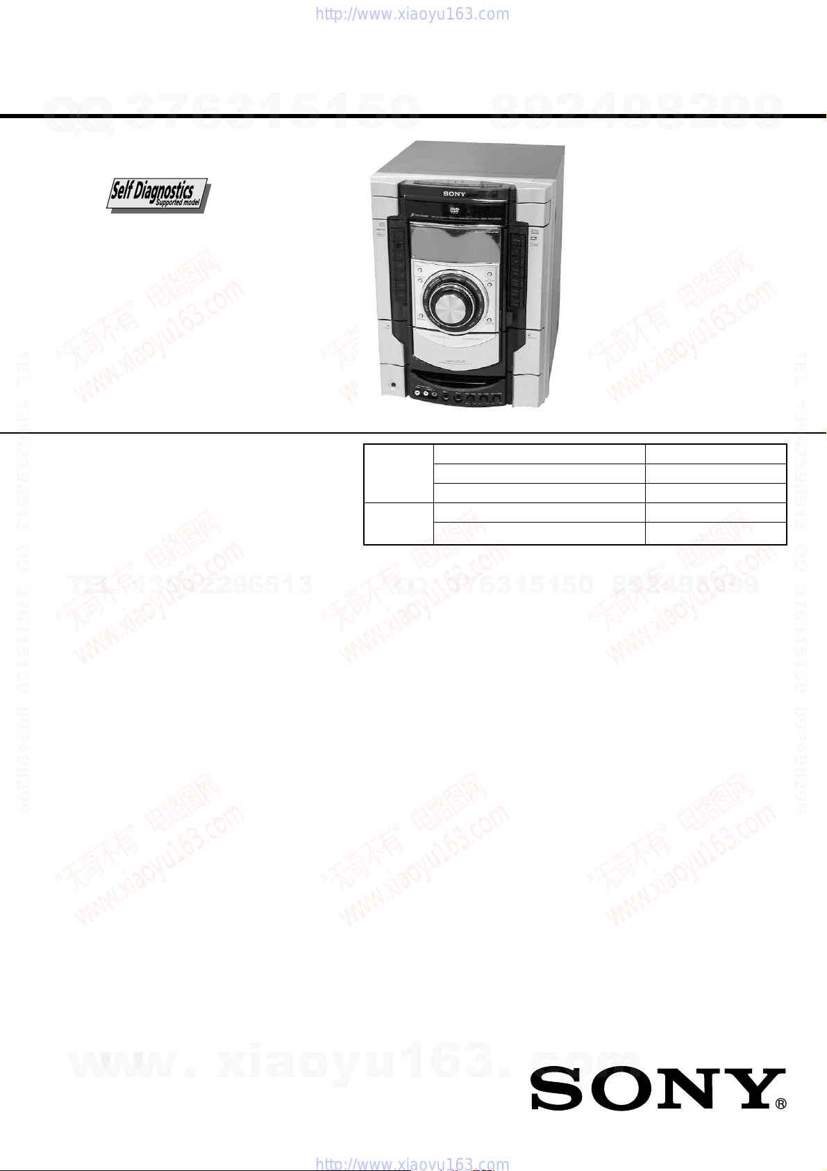
HCD-GN1000D
Q
Q
3
7
6
3
1
5
1
5
0
SERVICE MANUAL
Ver.1.0 2006.05
TEL 13942296513 QQ 376315150 892498299
• HCD-GN1000D is the Amplifier,
DVD player, tape deck and tuner
section in MHC-GN1000D.
DVD
Section
TAPE
Section
Model Name Using Similar Mechanism HCD-GNV111D
DVD Mechanism Type CDM74HF-DVBU101
Optical Pick-up Name KHM-310CAB/C2NP
Model Name Using Similar Mechanism NEW
Tape Transport Mechanism Type CWN42RR603
8
9
2
4
9
8
2
9
E Model
9
TEL 13942296513 QQ 376315150 892498299
Amplifier section
TEL
13942296513
The following are measured at AC 120, 127, 220,
240V 50/60 Hz
DIN power output (rated): 125 W + 125 W
Continuous RMS power output (reference)
Front speaker: 170 W + 170 W
Center speaker: 70 W
Surround speaker: 70 W + 70 W
Subwoofer: 210 W (8 ohms at 100 Hz,
Inputs
VIDEO INPUT (phono jacks):
TV/SAT AUDIO IN L/R (phono jacks):
MIC 1 or 2 (phone jack): Sensitivity 1 mV,
AUDIO OUT (phono jacks):
(6 ohms at 1 kHz, DIN)
(6 ohms at 1 kHz, 10%
THD)
(6 ohms at 1 kHz, 10%
THD)
(6 ohms at 1 kHz, 10%
THD)
10% THD)
VIDEO: 1 Vp-p, 75 ohms
AUDIO L/R: Voltage
250 mV, impedance 47
kilohms
Voltage 250 mV/450 mV,
impedance 47 kilohms
impedance 10 kilohms
Outputs
Voltage 250 mV,
impedance 1 kilohm
SPECIFICATIONS
6
7
3
Q
Q
VIDEO OUT (phono jack):
COMPONENT VIDEO OUT:
S VIDEO OUT (4-pin/mini-DIN jack):
PHONES (stereo mini jack):
FRONT SPEAKER: Use only the supplied
SURR SPEAKER: Use only the supplied
CENTER SPEAKER: Use only the supplied
SUBWOOFER OUT:
MINI HI-FI COMPONENT SYSTEM
3
1
5
1
5
2
9
8
0
Max. output level 1 Vp-p,
unbalanced, Sync.
negative load impedance
75 ohms
Y: 1 Vp-p, 75 ohms
PB/CB: 0.7 Vp-p, 75 ohms
PR/CR: 0.7 Vp-p, 75 ohms
Y: 1 Vp-p, unbalanced,
Sync. negative
C: 0.286 Vp-p, load
impedance 75 ohms
accepts headphones of
8 ohms or more
speakers
speakers
speaker
Use only the supplied
subwoofer
9
9
2
8
9
4
– Continued on next page –
w
w
9-887-254-01
2006E02-1
© 2006.05
w
.
xia
Sony Corporation
Home Audio Division
Published by Sony Techno Create Corporation
o
y
u
1
6
3
.
c
o
m

HCD-GN1000D
Disc player section
System Compact disc and digital
Q
Q
Laser Semiconductor laser
Frequency response DVD (PCM 48 kHz):
Video color system format NTSC and PAL
Tape deck section
Recording system 4-track 2-channel stereo
Frequency response 50 – 13,000 Hz (±3 dB),
TEL 13942296513 QQ 376315150 892498299
Tuner section
FM stereo, FM/AM superheterodyne tuner
FM tuner section
Tuning range
Antenna FM lead antenna
Antenna terminals 75 ohms unbalanced
Intermediate frequency 10.7 MHz
AM tuner section
Tuning range
Saudi Arabian model:
Other models: 531 – 1,602 kHz
TEL
Antenna AM loop antenna
Antenna terminals External antenna terminal
Intermediate frequency 450 kHz
General
Power requirements
Saudi Arabian model: 120 – 127 V, 220 V or
Thai model: 220 V AC, 50/60 Hz
Other models: 120 V, 220 V or
7
3
13942296513
6
audio and video system
(DVD: λ = 650 nm,
CD: λ = 790 nm)
Emission duration:
continuous
2 Hz – 22 kHz (±1dB)
CD: 2 Hz – 20 kHz
(±0.5 dB)
using Sony TYPE I tape
87.5 – 108.0 MHz
(50 kHz step)
531– 1,602 kHz
(with the interval set at 9 kHz)
(with the interval set at 9 kHz)
530 – 1,710 kHz
(with the interval set at 10 kHz)
230 – 240 V AC, 50/60 Hz
Adjustable with voltage
selector
230 – 240 V AC, 50/60 Hz
Adjustable with voltage
selector
3
1
5
1
5
Self-diagnosis Function
0
(When letters/numbers appear in the
display)
When the self-diagnosis function is activated to
prevent the system from malfunctioning, a
5-character service number (e.g. C 13 50) with a
combination of a letter and 4 digits appears on
the TV screen and the front panel display. In this
case, check the following table.
First 3
characters of
the service
number
C 13 This disc is dirty.
C 31 The disc is not inserted correctly.
E XX
(XX is a
number)
When displaying the version number on the
TV screen
When you turn on the system, the version
number [VER.X.XX] (X is a number) may
Q
Q
appear on the TV screen. Although this is not a
malfunction and for Sony service use only,
normal system operation will not be possible.
Turn off the system, and then turn on the system
again to operate.
Cause and corrective action
Clean the disc with a soft cloth
(page 87).
Restart the system, then re-insert
the disc correctly.
To prevent a malfunction, the system
has performed the self-diagnosis
function.
Contact your nearest Sony dealer or
local authorized Sony service
facility and give the 5-character
service number.
Example: E 61 10
7
3
VER.X.XX
8
6
3
9
1
5
2
1
5
4
0
9
8
9
8
2
4
2
9
8
9
2
9
9
TEL 13942296513 QQ 376315150 892498299
9
Power consumption 345 W
Dimensions (w/h/d) (Approx.) 281 × 362 × 404.5 mm
Mass (Approx.) 16.0 kg
Design and specifications are subject to change without notice.
w
w
w
2
.
xia
o
y
u
1
6
3
.
c
o
m

TABLE OF CONTENTS
7
Q
Q
TEL 13942296513 QQ 376315150 892498299
TEL
3
1. SERVICING NOTES ................................................ 4
2. GENERAL ................................................................... 5
3. DISASSEMBLY
3-1. Disassembly Flow ........................................................... 7
3-2. Case ................................................................................. 8
3-3. Loading Panel.................................................................. 8
3-4. Tuner Pack....................................................................... 9
3-5. DVD Mechanism Deck ................................................... 9
3-6. Front Panel Assy.............................................................. 10
3-7. Tape Mechanism Deck, MIC Board ................................ 10
3-8. CD-SW Board, Panel Board............................................ 11
3-9. FUNCTION Board, JOG Board ...................................... 11
3-10. KARAOKE Board, VIDEO Board, DMB15 Board........ 12
3-11. Back Panel ....................................................................... 12
3-12. PRIMARY Board, EFFECTOR Board............................ 13
3-13. Power AMP PC Board Assy, MAIN Board ..................... 13
3-14. SURROUND Board, PA Board ....................................... 14
3-15. Power Transformer (T1200)........................................... 14
3-16. DRIVER Board, SW Board............................................. 15
3-17. DVD Assy........................................................................ 15
3-18. Optical Pick-up................................................................ 16
3-19. SENSOR Board ............................................................... 16
3-20. MOTOR (TB) Board ....................................................... 17
3-21. MOTOR (LD) Board....................................................... 17
4. TEST MODE ............................................................... 18
5. MECHANICAL ADJUSTMENTS......................... 23
13942296513
6. ELECTRICAL ADJUSTMENTS .......................... 23
6
3
1
5
1
5
0
Q
Q
7. DIAGRAMS .......................................................... 25
7-1. Block Diagram – RF Section –....................................... 27
7-2. Block Diagram – Video Section – ................................... 28
7-3. Block Diagram – Tape/Tuner Section – .......................... 29
7-4. Block Diagram – Main Section – .................................... 30
7-5. Block Diagram – AMP Section – .................................... 31
7-6. Block Diagram – Display/Power Section –..................... 32
7-7. Printed Wiring Board – DMB15 Board (Side A) – ......... 33
7-8. Printed Wiring Board – DMB15 Board (Side B) – ........ 34
7-9. Schematic Diagram – DMB15 Board (1/4) –................ 35
7-10. Schematic Diagram – DMB15 Board (2/4) –................ 36
7-11. Schematic Diagram – DMB15 Board (3/4) –................ 37
7-12. Schematic Diagram – DMB15 Board (4/4) –................ 38
7-13. Printed Wiring Boards – CD Mechanism Boards – ....... 39
7-14. Schematic Diagram – CD Mechanism Boards –........... 40
7-15. Printed Wiring Board – MAIN Board – .......................... 41
7-16. Schematic Diagram – MAIN Board (1/5) – ................... 42
7-17. Schematic Diagram – MAIN Board (2/5) – ................... 43
7-18. Schematic Diagram – MAIN Board (3/5) – ................... 44
7-19. Schematic Diagram – MAIN Board (4/5) – ................... 45
7-20. Schematic Diagram – MAIN Board (5/5) – ................... 46
7-21. Printed Wiring Board – PANEL Board – ........................ 47
7-22. Schematic Diagram – PANEL Board – .......................... 48
7-23. Printed Wiring Boards – CD-SW, JOG, FUNCTION
7-24. Schematic Diagram – CD-SW, JOG, FUNCTION
7-25. Printed Wiring Board – PA Board – ................................ 51
7-26. Schematic Diagram – PA Board – .................................. 52
7-27. Printed Wiring Board – SURROUND Board –............... 53
7-28. Schematic Diagram – SURROUND Board (1/2) –........ 54
7
3
7-29. Schematic Diagram – SURROUND Board (2/2) –....... 55
7-30. Printed Wiring Board – EFFECTOR Board – ................. 56
7-31. Schematic Diagram – EFFECTOR Board –................... 57
7-32. Printed Wiring Board – VIDEO Board – ........................ 58
7-33. Schematic Diagram – VIDEO Board – .......................... 59
7-34. Printed Wiring Boards – Power Section –....................... 60
7-35. Schematic Diagram – Power Section – .......................... 61
7-36. Printed Wiring Board – KARAOKE Board – ................. 62
7-37. Schematic Diagram – KARAOKE Board – ................... 62
7-38. IC Pin Function Description............................................ 65
HCD-GN1000D
4
2
9
8
And MIC Boards – .......................................................... 49
And MIC Boards – .......................................................... 50
0
5
1
5
1
3
6
9
8
9
2
8
4
2
9
8
9
2
9
9
9
TEL 13942296513 QQ 376315150 892498299
w
w
w
.
xia
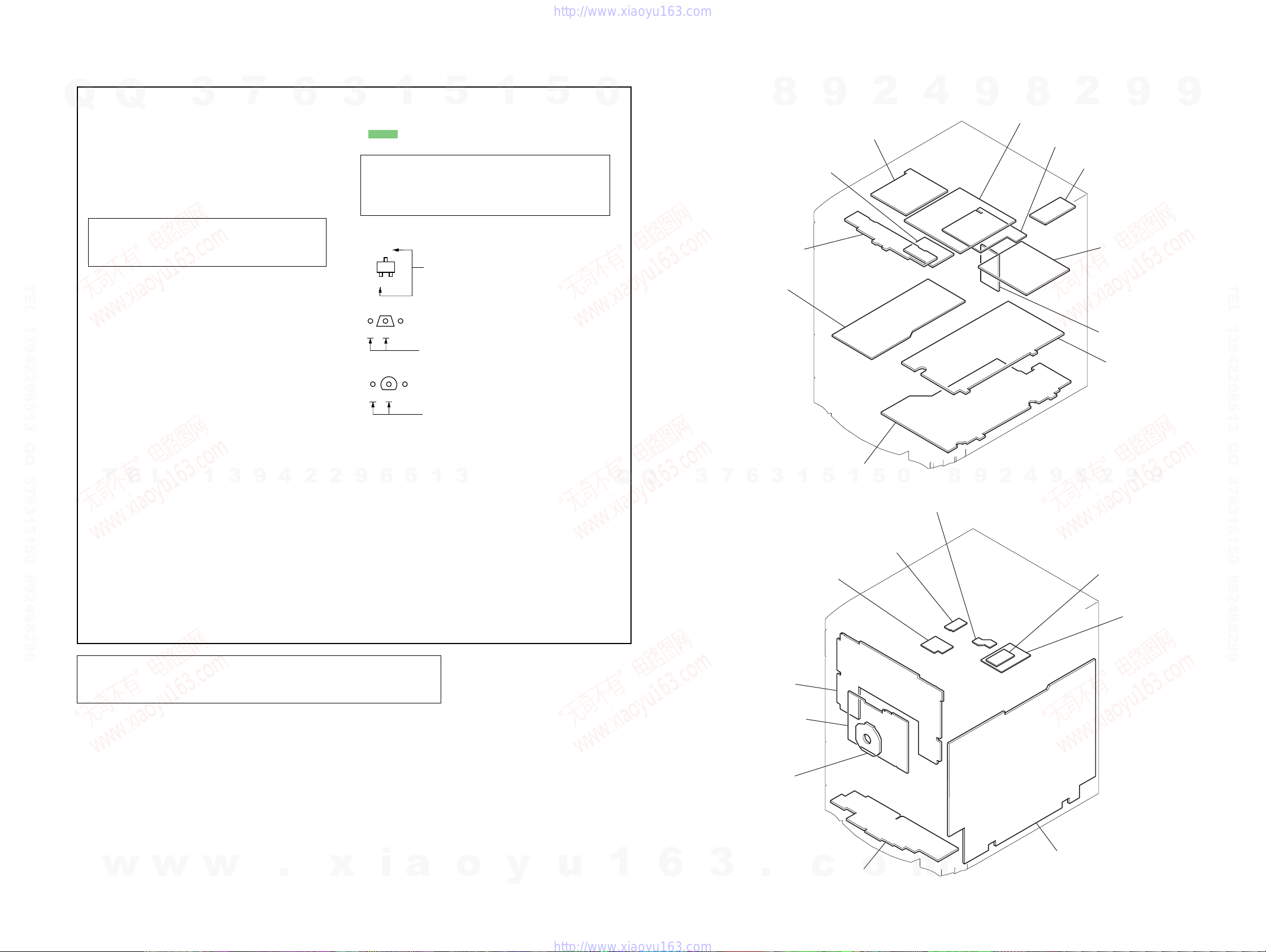
8. EXPLODED VIEWS
8-1. Case, Back Panel Section ................................................ 75
8-2. Front Panel Section-1 ...................................................... 76
8-3. Front Panel Section-2 ...................................................... 77
8-4. Chassis Section................................................................ 78
8-5. DVD Mechanism Section-1 (CDM74HF-DVBU101).... 79
8-6. DVD Mechanism Section-2 (CDM74HF-DVBU101).... 80
9. ELECTRICAL PARTS LIST .................................. 81
o
y
u
1
6
3
.
c
o
m
3
HCD-GN1000D
SECTION 1
SERVICING NOTES
NOTES ON HANDLING THE OPTICAL PICK-UP BLOCK
OR BASE UNIT
Q
Q
The laser diode in the optical pick-up block may suffer electrostatic
break-down because of the potential difference generated by the
charged electrostatic load, etc. on clothing and the human body.
During repair, pay attention to electrostatic break-down and also
use the procedure in the printed matter which is included in the
repair parts.
The flexible board is easily damaged and should be handled with
care.
NOTES ON LASER DIODE EMISSION CHECK
The laser beam on this model is concentrated so as to be focused on
the disc reflective surface by the objective lens in the optical pick-
TEL 13942296513 QQ 376315150 892498299
up block. Therefore, when checking the laser diode emission,
observe from more than 30 cm away from the objective lens.
LASER DIODE AND FOCUS SEARCH OPERATION
CHECK
Carry out the “S curve check” in “CD section adjustment” and check
that the S curve waveform is output several times.
CAUTION
Use of controls or adjustments or performance of procedures
other than those specified herein may result in hazardous
radiation exposure.
3
7
6
3
1
5
1
5
UNLEADED SOLDER
Boards requiring use of unleaded solder are printed with the lead-
0
free mark (LF) indicating the solder contains no lead.
(Caution: Some printed circuit boards may not come printed with
the lead free mark due to their particular size)
: LEAD FREE MARK
Unleaded solder has the following characteristics.
• Unleaded solder melts at a temperature about 40 °C higher
than ordinary solder.
Ordinary soldering irons can be used but the iron tip has to be
applied to the solder joint for a slightly longer time.
Soldering irons using a temperature regulator should be set to
about 350 °C.
Caution: The printed pattern (copper foil) may peel away if
the heated tip is applied for too long, so be careful!
• Strong viscosity
Unleaded solder is more viscou-s (sticky, less prone to flow)
than ordinary solder so use caution not to let solder bridges
occur such as on IC pins, etc.
• Usable with ordinary solder
It is best to use only unleaded solder but unleaded solder may
also be added to ordinary solder.
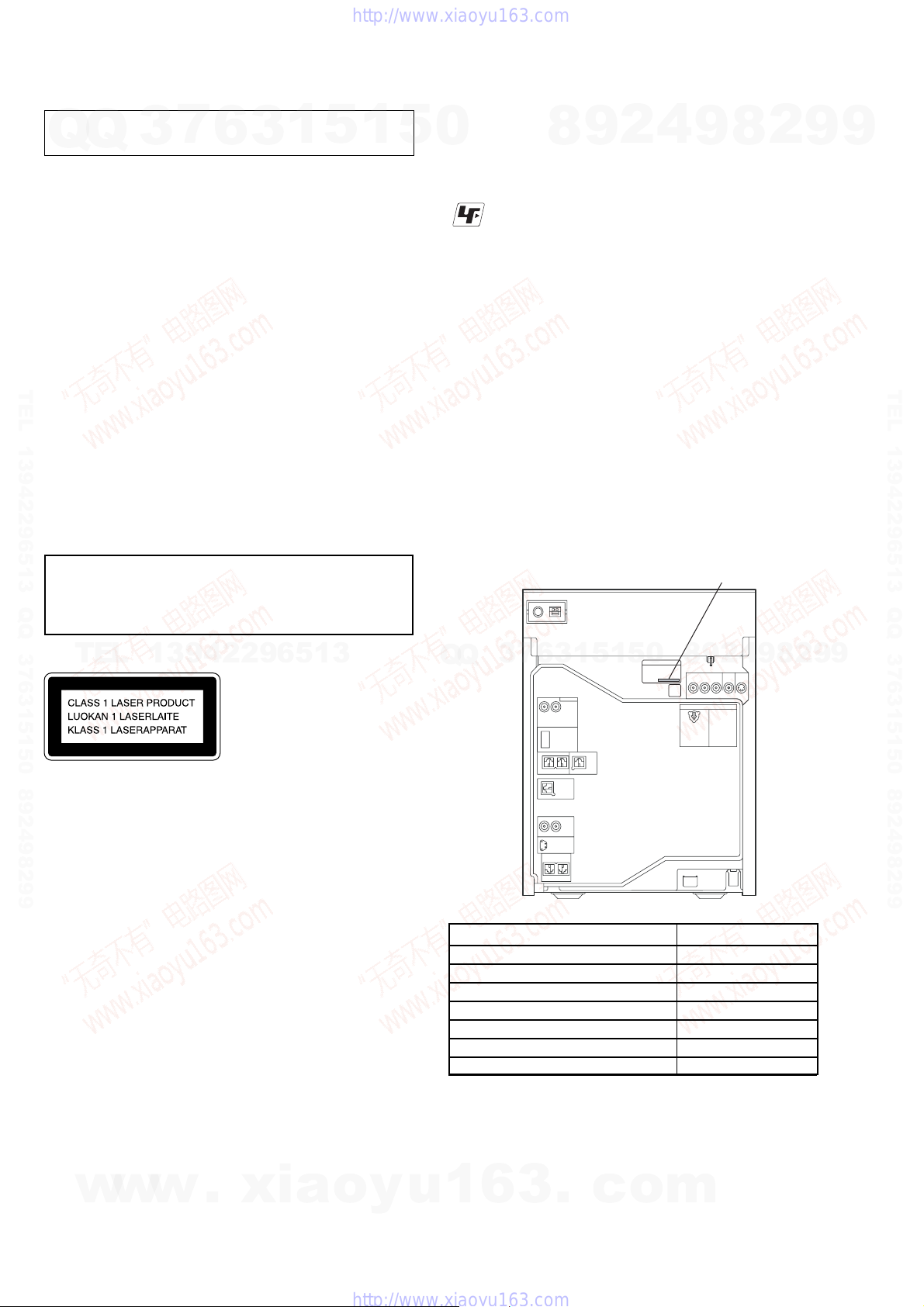
• MODEL IDENTIFICATION
– Back Panel –
8
9
2
4
9
PART No.
8
2
9
9
TEL 13942296513 QQ 376315150 892498299
TEL
Notes on chip component replacement
• Never reuse a disconnected chip component.
• Notice that the minus side of a tantalum capacitor may be
damaged by heat.
Flexible Circuit Board Repairing
• Keep the temperature of soldering iron around 270˚C
during repairing.
• Do not touch the soldering iron on the same conductor of the
circuit board (within 3 times).
• Be careful not to apply force on the conductor when soldering
or unsoldering.
NOTE ON REPLACEMENT OF DMB15 BOARD
New part of EEPROM (IC103) on the DMB15 board can not be
used. Therefore, if the mounted DMB15 board (A-1174-274-A or
A-1193-178-A or A-1193-183-A or A-1193-188-A) is replaced,
exchange new EEPROM with that used before the replacement.
SAFETY-RELATED COMPONENT WARNING!!
COMPONENTS IDENTIFIED BY MARK 0 OR DOTTED LINE WITH
MARK 0 ON THE SCHEMATIC DIAGRAMS AND IN THE PARTS
LIST ARE CRITICAL TO SAFE OPERATION. REPLACE THESE
w
COMPONENTS WITH SONY PARTS WHOSE PART NUMBERS
APPEAR AS SHOWN IN THIS MANUAL OR IN SUPPLEMENTS
PUBLISHED BY SONY .
13942296513
This appliance is classified as
a CLASS 1 LASER product.
This label is located on the rear
exterior.
w
w
.
xia
o
y
u
8
0
5
1
5
1
3
6
7
3
Q
Q
MODEL PART No.
E2 model 2-661-760-4[]
E3,E15 models 2-672-142-2[]
EA model 2-686-972-0[]
E12 model 2-686-973-0[]
MY,SP models 2-686-974-0[]
TH model 2-686-975-0[]
PH model 2-686-976-0[]
• Abbreviation
E2 : 120V AC Area in E model
E3 : 240V AC Area in E model
E12 : 220V-240V AC Area in E model
E15 : Iran model
EA : Saudi Arabia model
MY : Malaysia model
1
6
3
.
c
o
PH : Philippines model
SP : Singapore model
TH : Thai model
m
9
2
4
9
8
2
9
9
4
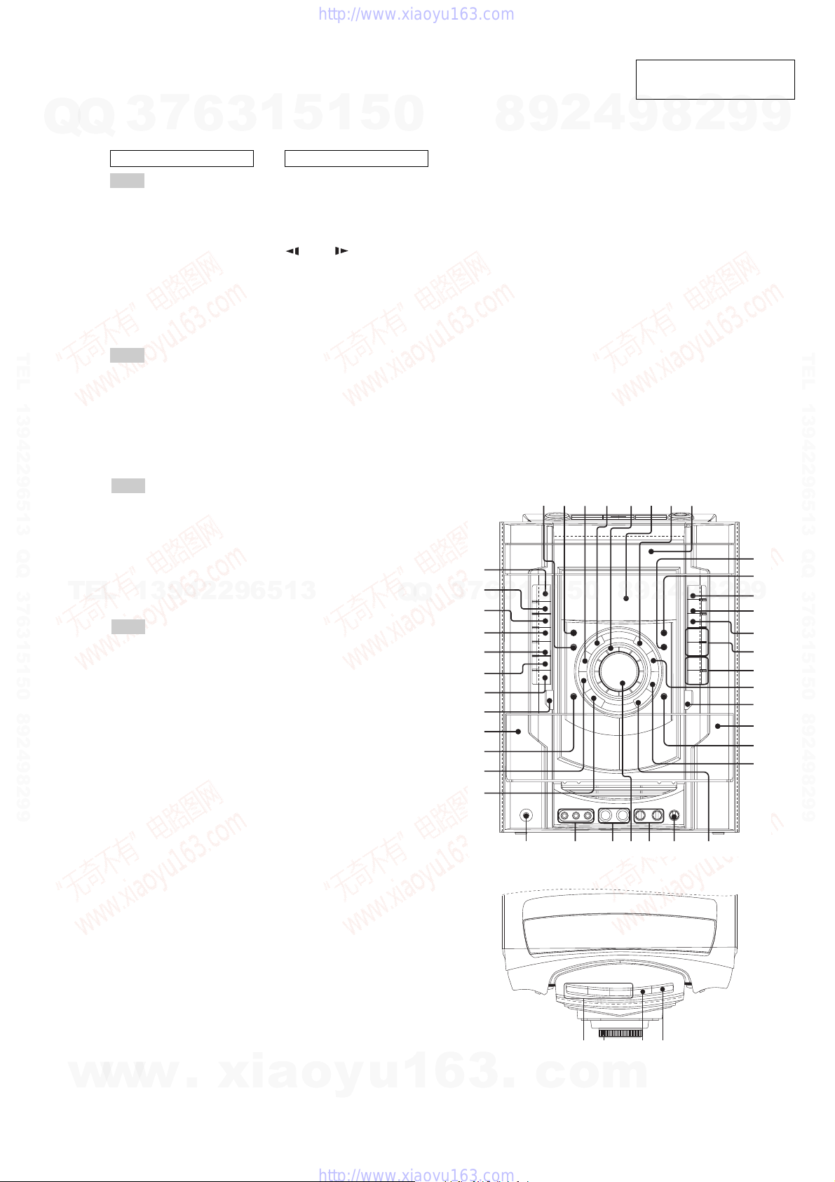
Top Panel
Front Panel
12
34 5678
9
q;
qa
qs
qd
qf
qg
qh
qj
qk
w
a
w;
ql
w
s
wdw
f
w
g
w
h
w
j
e;
wl
wk
ea
es
ed
ef
eg
eh
ej
ek
el
tsta t; rl
SECTION 2
GENERAL
LOCA TING THE CONTROLS
7
Q
Q
TEL 13942296513 QQ 376315150 892498299
TEL
3
Unit
ALPHABETICAL ORDER
A - D
AMP MENU e;
CD SYNC q;
Deck A ea
Deck B qk
DELAY wl
DIRECTION ql
DISC 1 ~ 3 ts
Disc tray 8
DISPLAY 2
Display 6
DVD ej
E - L
ECHO LEVEL ws
ENTER wa
EQ BAND w;
EX-CHANGE/DISC SKIP t;
FLANGER 3
GROOVE qh
ILLUMINATION 1
IR Receptor ek
M - R
MASTER VOLUME wf
MIC 1/2 (jack) wg
MIC 1/2 LEVEL wd
OPERATION DIAL ta
PHONES (jack) wj
Power illuminator 5
PRESET +/- qf
13942296513
PROGRESSIVE 7
REC PAUSE/START 9
S - Z
SOUND FIELD 4
SOUND FLASH wk
TAPE A/B eg
TUNER/BAND eh
TUNING +/- qg
TV/SAT ef
VIDEO INPUT (jacks) wh
VIDEO ed
6
3
1
5
1
5
SYMBOLS
?/1 (on/standby) el
Z OPEN/CLOSE rl
nN (play) qa
.> (go b ackward/forward)
qf
mM (rewind/fast
forward) qg
X (pause) qs
x (stop) qd
A Z (Eject A) es
B Z (Eject B) qj
0
Q
Q
3
7
8
6
3
9
1
5
2
1
5
4
0
HCD-GN1000D
This section is extracted
from instruction manual.
2
8
9
2
8
9
4
2
9
8
9
9
9
TEL 13942296513 QQ 376315150 892498299
9
w
w
w
.
xia
o
y
u
1
6
3
.
c
o
m
5
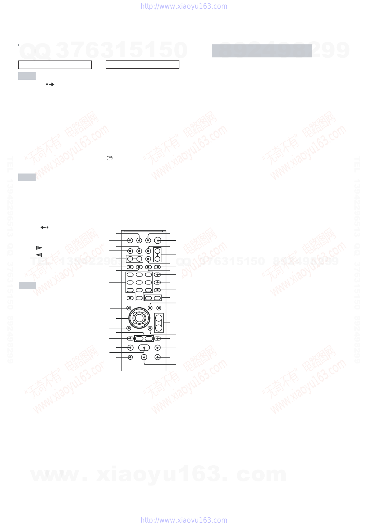
HCD-GN1000D
Remote control
Q
Q
ALPHABETICAL ORDER
A - L
ADVANCE wf
ALBUM +/- qa
ANGLE q;
AUDIO 8
CLEAR wk
DISC SKIP 3
DISPLAY ed
ENTER wh
FM MODE 7
FUNCTION +/- 4
KARAOKE MODE ea
TEL 13942296513 QQ 376315150 892498299
KARAOKE PON e;
KEY CONTROL #/2 es
M - S
MENU qs
Numeric Buttons
PICTURE NAVI 6
PRESET + qh
PRESET - wd
REPEAT 7
REPLAY wf
SCORE 5
SLEEP eg
SLOW qj
SLOW ws
SOUND FIELD qd
TEL
STEP C wf
SUBTITLE 9
T - Z
THEATRE SYNC 1
TIMER MENU eh
TIME/TEXT ef
TOP MENU wj
TUNING + qj
TUNING - ws
TV w;
TV CH + qh
TV CH - wd
TV/VIDEO eg
TV VOL +/TV &/1
VOLUME +/-
1)
qf
(on/standby) 2
1)
7
3
1)
wl
6
13942296513
qf
1
3
NUMBERS AND SYMBOLS
?/1 (on/standby) 2
x (stop) qk
X (pause) ql
1)
(play) wa
H
> (go forward) qh
. (go backward) wd
M (fast forward) qj
m (rewind) ws
V/v/B/b
10/0 wl
-/-- wk
O RETURN wg
DISPLAY qg
c STEP wf
1)
The numeric button 5, TV VOL
+, VOLUME + and H
buttons have a tactile dot. Use
the tactile dot as a reference
when operating the system.
eh
eg
ef
ed
es
ea
e;
wl
wk
wj
wh
wg
wf
wd
ws
wa
w;
5
wh
1
5
0
1
3
5
7
9
qa
qd
qf
qh
qk
2
4
Q
6
8
q;
qs
qg
qj
ql
Q
1
2
3
4
5
6
To adjust the clock
1
2
3
Notes
The clock settings are canceled when you disconnect
You cannot set the clock in Po wer Saving Mode
7
3
Setting the clock
9
8
Press ?/1 to turn on the system.
Press TIMER MENU.
The hour indication flashes in the display.
Press V or v repeatedly to set the
hour.
Press ENTER.
The minute indication flashes in the
display.
Press V or v repeatedly to set the
minute.
Press ENTER.
The clock starts functioning.
Press TIMER MENU.
“PLAY SET?” flashes in the display.
Press V or v repeatedly to select “CLOCK
SET?”, then press ENTER.
The hour indication flashes in the display.
Do the same procedures as step 3 to 6
above.
the power cord or if a power failure occurs.
5
1
3
6
2
1
5
4
0
9
8
9
8
2
4
2
9
8
9
2
9
9
TEL 13942296513 QQ 376315150 892498299
9
6
w
w
w
.
xia
o
y
u
1
6
3
.
c
o
m
Q
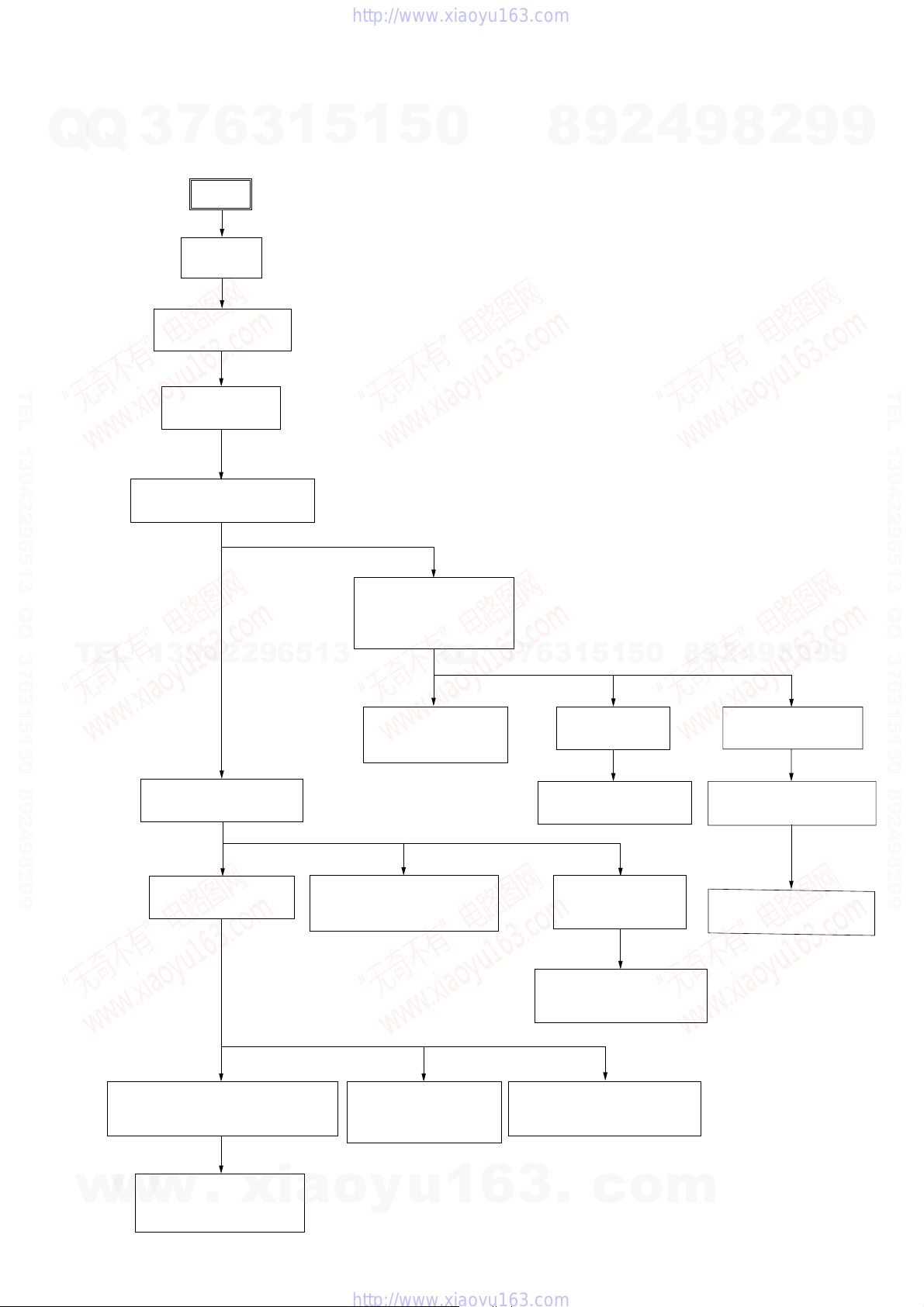
Note:
• This set can be disassembled in the order shown below.
Q
3-1. DISASSEMBLY FLOW
7
3
3-3. LOADING PANEL
6
SET
3-2. CASE
(Page 8)
(Page 8)
3
1
5
SECTION 3
DISASSEMBLY
1
5
0
8
9
2
4
HCD-GN1000D
2
8
9
9
9
TEL 13942296513 QQ 376315150 892498299
3-4. TUNER P A CK
(Page 9)
TEL
3-5. DVD MECHANISM DECK
13942296513
3-6. FRONT PANEL ASSY
(Page 9)
(Page 10)
3-10. KARAOKE BOARD,
VIDEO BOARD,
DMB15 BOARD,
(Page 12)
Q
Q
3-16. DRIVER BOARD,
SW BOARD
(Page 15)
3
7
0
5
1
5
1
3
6
3-17. DVD ASSY
(Page 15)
3-18. OPTICAL PICK-UP
(Page 16)
8
9
4
2
9
8
3-19. SENSOR BOARD
(Page 16)
3-20. MOTOR (TB) BOARD
(Page 17)
2
9
TEL 13942296513 QQ 376315150 892498299
9
3-11. BACK PANEL
(Page 12)
3-13. POWER AMP PC BOARD ASSY,
w
w
MAIN BOARD
(Page 13)
3-14. SURROUND BOARD,
w
.
PA BOARD
(Page 14)
xia
3-7. TAPE MECHANISM DECK,
MIC BOARD
(Page 10)
3-12. PRIMARY BOARD
EFFECTOR BOARD
(Page 13)
o
y
u
1
6
3-8. CD-SW BOARD,
PANEL BOARD
(Page 11)
3-9. FUNCTION BOARD,
JOG BOARD
(Page 11)
3-15. POWER TRANSFORMER
3
.
(T1200)
(Page 14)
c
o
m
3-21. MOTOR (LD) BOARD
(Page 17)
7
)
HCD-GN1000D
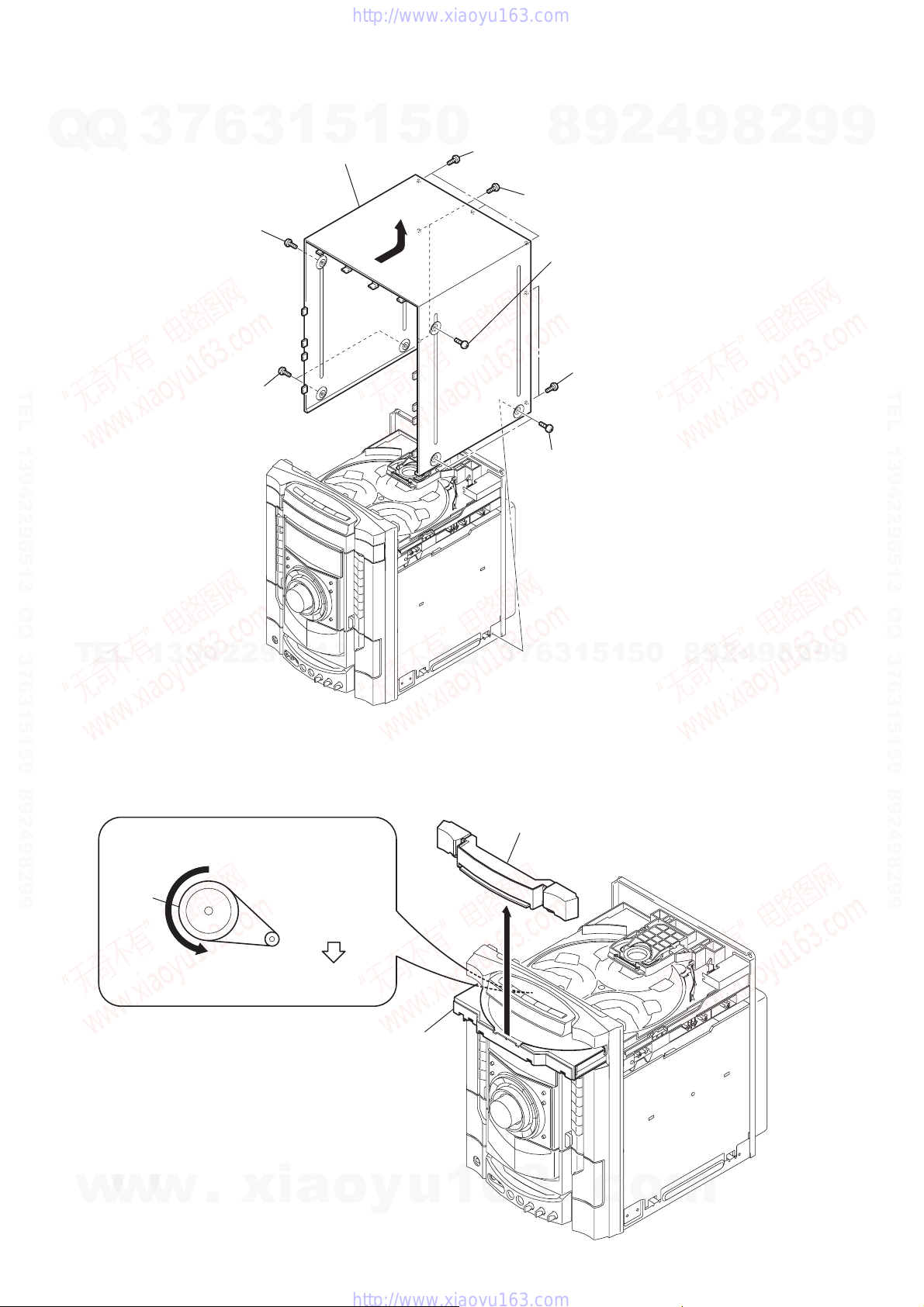
3-2. CASE
7
Q
Q
TEL 13942296513 QQ 376315150 892498299
3
6
4
screw
(case 3 TP2)
(3×12)
two screws
3
(case 3 TP2)
(3×8)
3
1
5
9
1
CASE
8
5
0
7
(+BVTP 3×8)
three screws
6
(+BVTP 3×12)
9
8
two screws
2
screw (case 3 TP2
(3×12)
5
two screws
(+BVTP 3
1
two screws
(case 3 TP2)
(3
×
8)
2
×
4
12)
9
8
2
9
9
TEL 13942296513 QQ 376315150 892498299
TEL
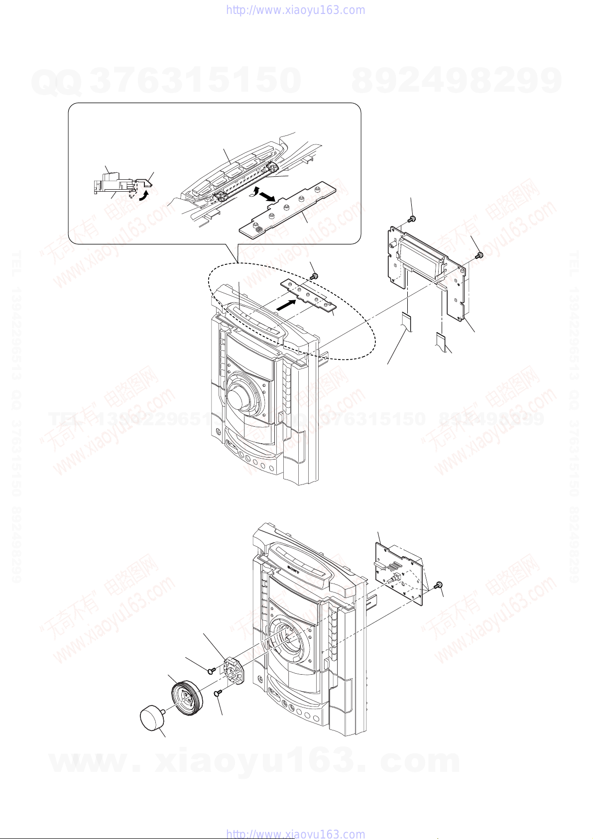
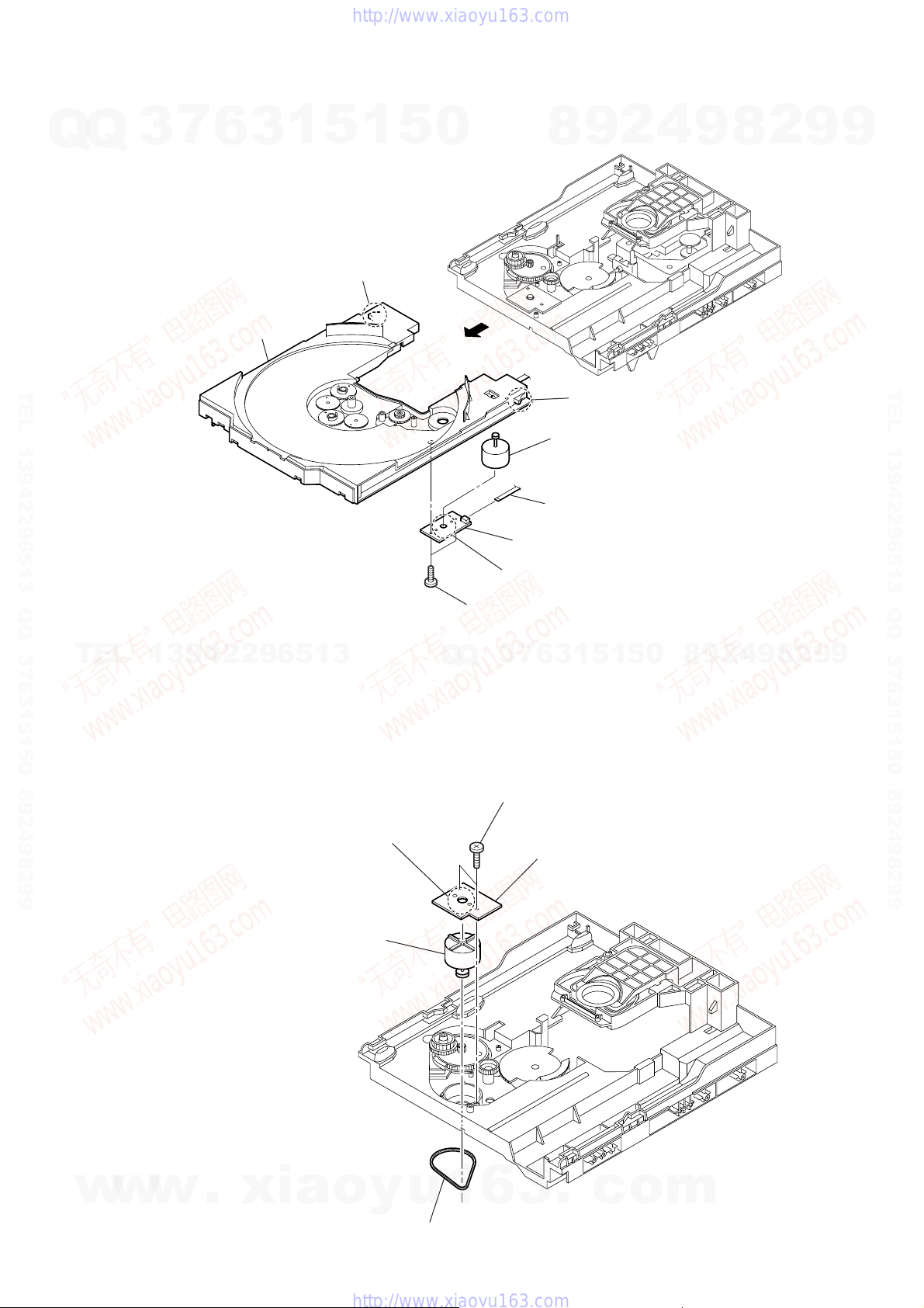
3-3. LOADING PANEL
13942296513
DVD mechanism deck (CDM74HF-DVBU101)
1
Turn the pulley to the arrow direction.
Pulley
Front side
2
Pull out disc tray.
Q
Q
3
3
3
6
7
loading panel
4
1
5
1
5
0
8
9
2
4
9
8
2
9
9
8
w
w
w
.
xia
o
y
u
1
6
3
.
c
o
m
Q
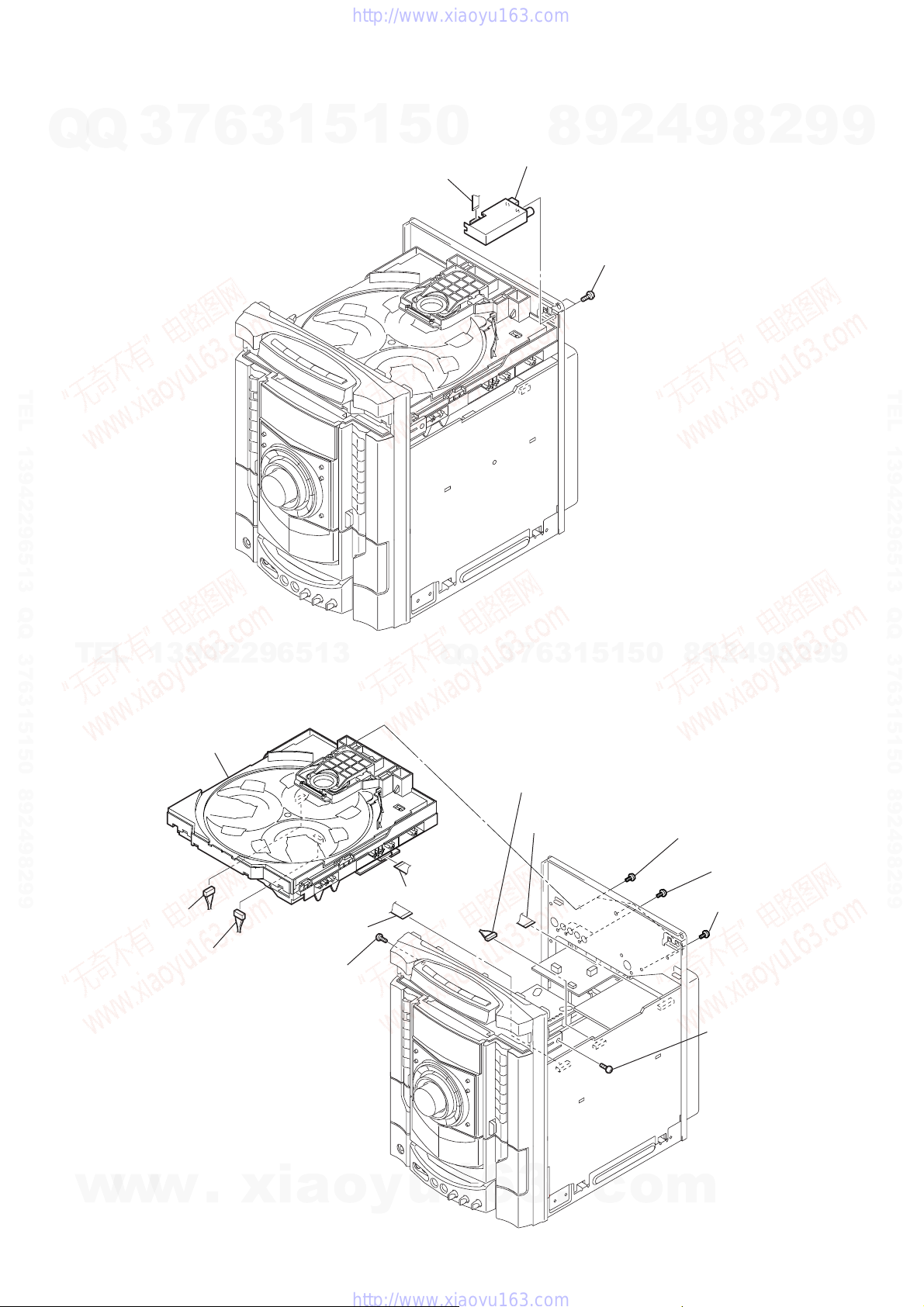
3-4. TUNER PACK
7
Q
3
6
3
1
5
1
5
0
2
wire (flat type)
(CN1)
8
3
tuner pack
2
9
1
two screws
(+BVTP 3
4
×
8)
HCD-GN1000D
2
8
9
9
9
TEL 13942296513 QQ 376315150 892498299
TEL
13942296513
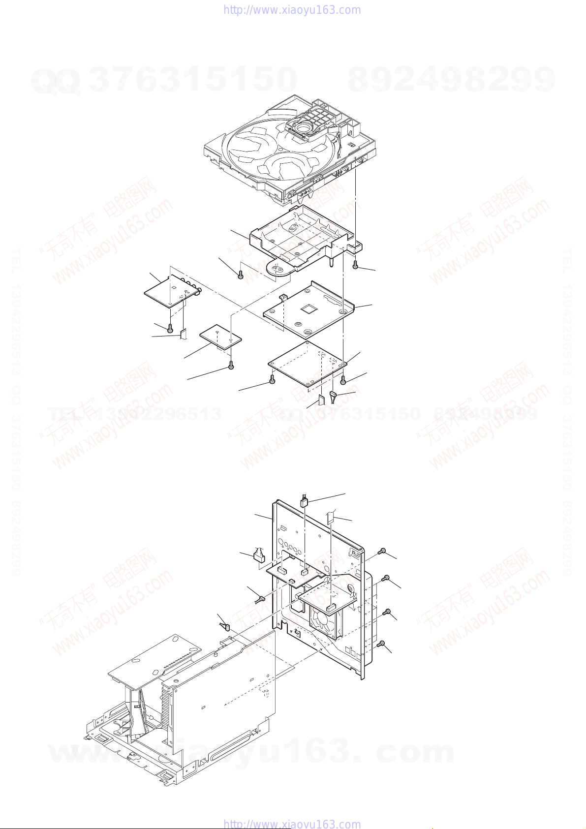
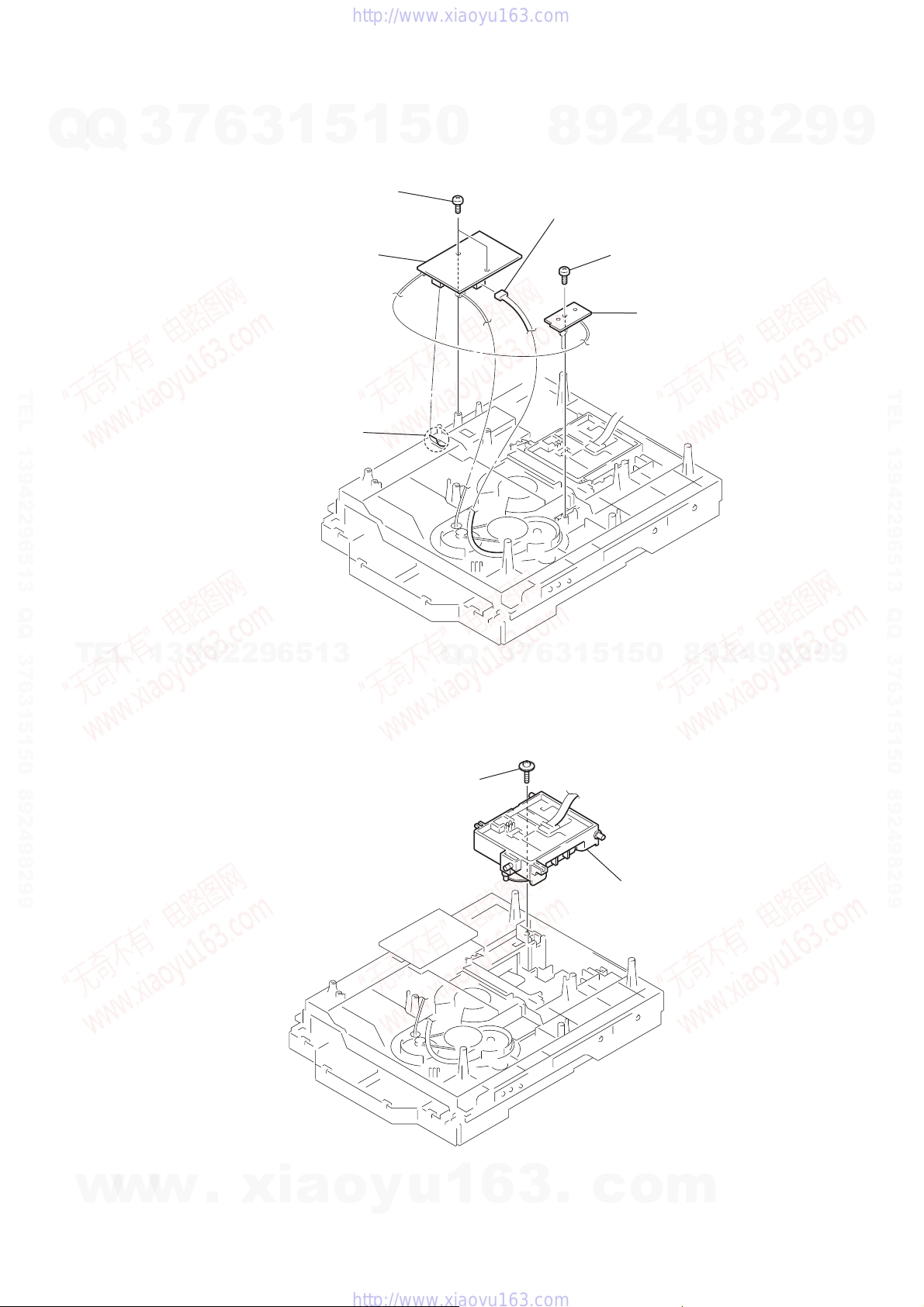
3-5. DVD MECHANISM DECK
6
DVD mechanism deck
qs
connector
(CN800)
qa
connector
(CN401)
0
wire (flat type)
(CN520)
5
screw
(+BVTP 3
×
10)
Q
7
wire (flat type)
(CN701)
Q
7
3
9
connector
(CN505)
8
(CN521)
5
1
3
6
wire (flat type)
1
5
0
2
9
8
3
three screws
(+BVTP 3
1
three screws
(+BVTP 3
2
screw
(+BVTP 3
4
TEL 13942296513 QQ 376315150 892498299
9
9
2
8
9
×
10)
×
10)
×
10)
w
w
w
.
xia
o
y
u
1
6
3
.
c
o
m
4
screw
(+BVTP 3
×
10)
9
HCD-GN1000D
)
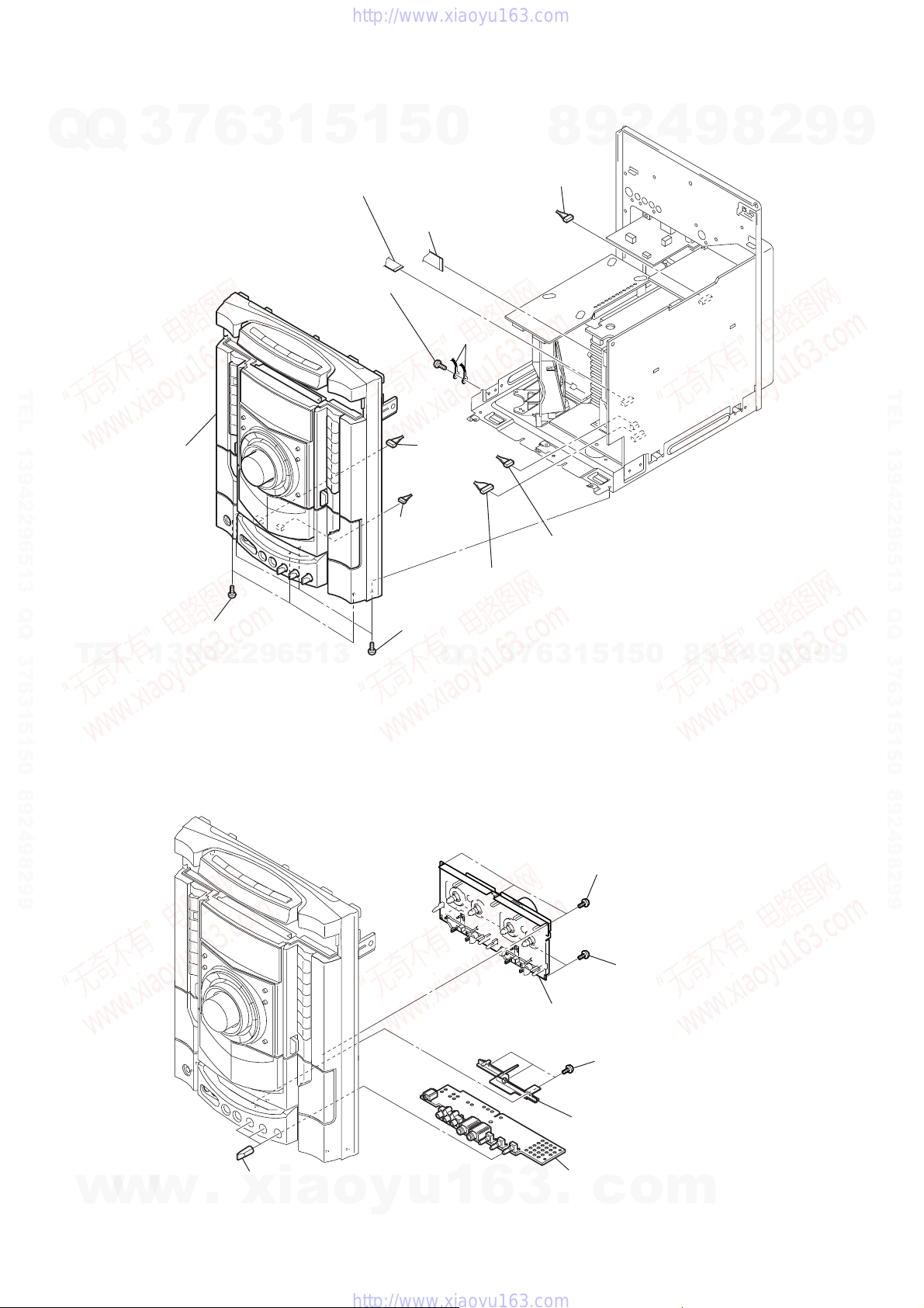
3-6. FRONT PANEL ASSY
7
Q
Q
3
6
1
3
1
(+BV3 (3-CR))
5
7
wire (flat type)
(CN509)
screw
1
5
6
wire (flat type)
(CN508)
0
lug
8
5
connector
(CN100)
9
2
4
9
8
2
9
9
TEL 13942296513 QQ 376315150 892498299
9
4
front panel assy
2
three screws
(+BVTP 3
TEL
3-7. TAPE MECHANISM DECK, MIC BOARD
13942296513
×
10)
connector
(CN1102)
qa
connector
(CN1100)
3
three screws
(+BVTP 3
Q
Q
×
10)
0
connector
(CN503)
7
3
8
connector
(CN504)
1
3
6
5
1
5
0
8
9
2
4
9
8
2
9
TEL 13942296513 QQ 376315150 892498299
9
10
w
w
w
.
xia
6
knob (MIC)
o
y
u
1
6
3
1
three screws
(+BVTP2.6 (3CR))
2
two screws
(+BVTP2.6 (3CR)
3
tape mechanism deck
4
three screws
(+BVTP2.6 (3CR))
5
bracket (MIC)
7
MIC board
.
c
o
m
d
Q
3-8. CD-SW BOARD, PANEL BOARD
7
Q
3
2
Pull up the bracket portion of button (DISC) in the arrow A direction and
pull out CD-SW board in the arrow
button (DISC)
CD-SW board
(side view)
6
bracket portion
A
3
1
button (DISC)
5
1
5
0
B
direction.
bracket portion
B
A
CD-SW board
8
4
2
9
4
three screws
(+BVTP2.6 (3CR))
HCD-GN1000D
2
8
9
5
three screws
(+BVTP2.6 (3CR))
9
9
TEL 13942296513 QQ 376315150 892498299
1
two screws
(+BVTP2.6 (3CR))
B
3
CD-SW board
3
Q
Q
7
TEL
13942296513
3-9. FUNCTION BOARD, JOG BOARD
button (DISC)
6
3
6
(CN900)
5
1
3
wire (flat type)
8
0
5
1
FUNCTION board
8
PANEL boar
7
wire (flat type)
(CN902)
4
2
9
9
8
2
9
TEL 13942296513 QQ 376315150 892498299
9
w
w
6
two screws
(+BVTP2.6 (3CR))
4
knob jog assy
w
.
7
JOG board
1
knob vol
xia
5
two screws
(+BVTP2.6 (3CR))
o
y
u
1
6
3
.
c
o
2
seven screws
(+BVTP2.6 (3CR))
m
11
)
HCD-GN1000D
3-10. KARAOKE BOARD, VIDEO BOARD,
DMB15 BOARD
Q
Q
TEL 13942296513 QQ 376315150 892498299
7
3
5
VIDEO board
6
1
3
8
CDM cover
6
screw
(+BVTP 3
5
×
10)
1
5
0
8
2
9
7
two screws
(+BVTP 3
4
×
10)
9
8
2
9
9
TEL 13942296513 QQ 376315150 892498299
4
two screws
(+BVTP 3
3
wire (flat type)
(CN801)
TEL
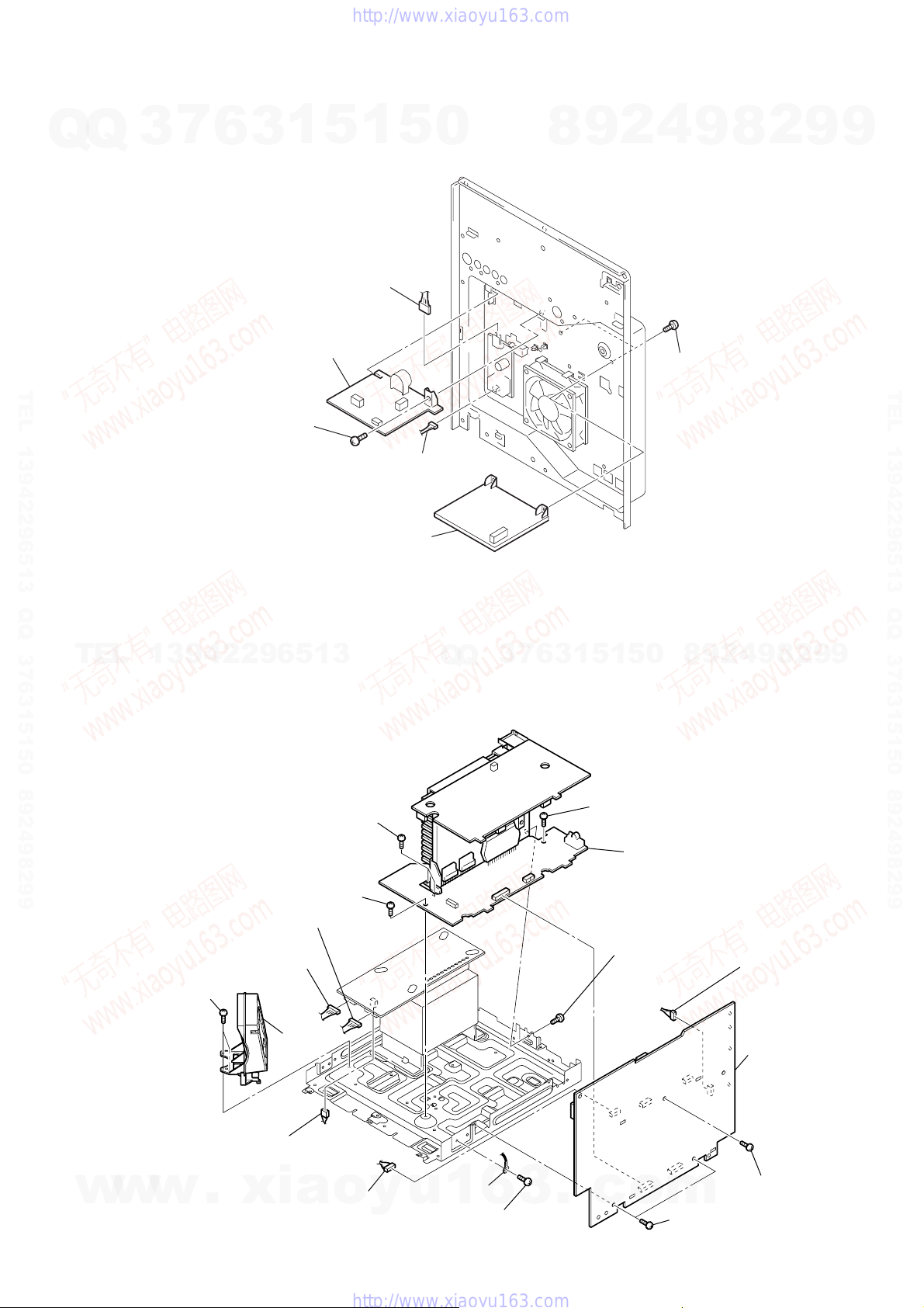
3-11. BACK PANEL
13942296513
×
10)
2
KARAOKE board
1
two screws
(+BVTP 3
×
10)
qs
two screws
(+BVTP 3
2
(CN1204)
0
connector
(CN580)
×
10)
9
back panel
connector
1
connector
(CN1200)
0
wire (flat type)
(CN101)
Q
Q
3
6
7
3
(CN1202)
qf
bracket (mediatec)
qd
DMB15 board
qa
two screws
(+BVTP 3
9
connector
(CN201)
1
5
1
3
connector
4
wire (flat type)
(CN1501)
×
10)
9
8
0
5
6
two screws
(+BVTP 3×10)
5
seven screws
(+BVTP 3×10)
8
two screws
(+BVTP 3×10)
2
4
9
8
2
9
9
12
w
w
w
.
xia
o
y
u
1
6
3
.
7
screw (+BVTP 3×10
c
o
m
)
3-12. PRIMARY BOARD ,EFFECTOR BOARD
7
Q
Q
TEL 13942296513 QQ 376315150 892498299
3
6
4
3
screw
(+BVTP 3
1
3
1
(CN101)
PRIMARY board
×
8)
5
connector
1
5
0
2
connector
(CN201)
8
9
2
4
9
5
two screws
(+BVTP 3
HCD-GN1000D
8
×
10)
2
9
9
TEL 13942296513 QQ 376315150 892498299
6
EFFECTOR board
TEL
13942296513
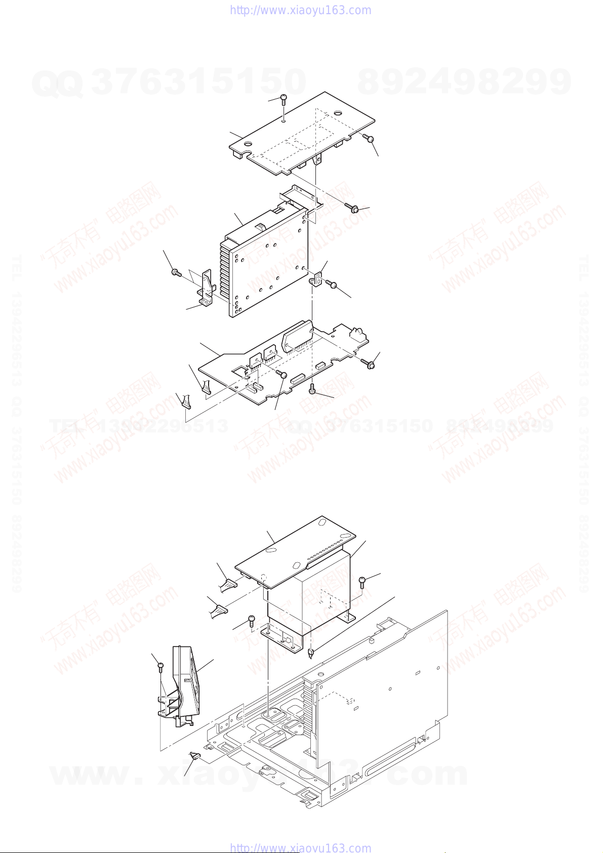
3-13. POWER AMP PC BOARD ASSY, MAIN BOARD
8
two screws
(+BV3 (3-CR))
7
screw
(+BV3 (3-CR))
5
connector
(CN1212)
2
two screws
(+BV3 (3-CR))
4
connector
(CN1213)
Q
Q
3
7
6
5
1
3
9
screw
(+BV3 (3-CR))
9
8
0
5
1
qa
power AMP PC board assy
0
screw
(+BVTP 3×10)
4
2
qs
connector
(CN105)
9
8
2
9
9
w
w
w
.
xia
3
DC fan
6
connector
(CN1215)
o
1
connector
y
(CN582)
u
1
lug
6
3
qd
screw
(+BVTP 3×8)
.
c
o
m
qf
two screws
(+BVTP 3×8)
qh
MAIN board
qg
screw
(+BVTP 3×8
13
HCD-GN1000D
3-14. SURROUND BOARD, PA BOARD
7
Q
Q
TEL 13942296513 QQ 376315150 892498299
3
6
4
7
two screws
(+BVTP 3
8
1
3
3
SURROUND board
×
holder
5
screw (+BV3 (3-CR))
qs
heat sink
10)
1
5
0
qf
bracket
9
8
2
two screws
(+BVTP 3
1
four screws
(transistor)
qd
screw
(+BVTP 3
2
×
10)
4
×
10)
9
8
2
9
9
TEL 13942296513 QQ 376315150 892498299
qg
PA board
6
connector
(CN607)
5
connector
(CN602)
TEL
3-15. PO WER TRANSFORMER (T1200)
13942296513
4
connector
(CN1213)
5
connector
(CN1212)
7
2
two screws
(+BV3 (3-CR))
three screws
TRANS board
3
DC fan
(M892)
qa
two screws
(+BVTP 3
Q
Q
9
(+BVTP 3
×
10)
7
3
0
(transistor)
two screws
1
3
6
9
power transfomer (T1200)
two screws
×
10)
1
5
8
three screws
6
connector
(CN1215)
5
0
8
9
2
4
9
8
2
9
9
14
w
w
w
.
xia
1
connector
(CN582)
o
y
u
1
6
3
.
c
o
m
Q
3-16. DRIVER BOARD, SW BOARD
Q
3
7
6
1
3
1
(+BTTP (M2.6))
4
DRIVER
5
1
5
0
two
screws
board
2
9
8
3
connector (CN703)
5
(+BTTP (M2.6))
screw
6
4
9
SW board
HCD-GN1000D
8
2
9
9
TEL 13942296513 QQ 376315150 892498299
2
wire (flat type)
(CN702)
TEL
13942296513
3-17. DVD ASSY
Q
Q
1
floating
(+PTPWH M2.6)
screw
3
7
6
3
1
5
1
5
0
8
9
2
4
9
8
2
9
TEL 13942296513 QQ 376315150 892498299
9
w
w
w
.
xia
o
y
u
1
6
3
.
c
2
DVD
o
assy
m
15

w
HCD-GN1000D
3-18. OPTICAL PICK-UP
7
Q
Q
TEL 13942296513 QQ 376315150 892498299
3
6
3
insulator screw
8
insulator
4
insulator screw
3
9
1
insulator
5
1
5
0
5
optical pick-up
(KHM-310CAB/C2NP)
2
7
2
9
8
insulator screw
insulator
1
insulator scre
6
insulator
4
9
8
2
9
9
TEL 13942296513 QQ 376315150 892498299
TEL
3-19. SENSOR BOARD
13942296513
2
t
ray
1
floating
(+PTPWH M2.6)
6
floating
(+PTPWH M2.6)
7
g
screw
8
(+BTTP (M2.6))
screw
ear (geneva)
s
crew
Q
Q
0
SENSOR board
9
connector
(
CN731)
9
9
2
8
9
4
2
9
8
0
5
1
5
1
3
6
7
3
3
b
elt (table)
4
floating
(+PTPWH M2.6)
5
screw
p
ulley (table)
16
w
w
w
.
xia
o
y
u
1
6
3
.
c
o
m
Q
3-20. MOTOR (TB) BOARD
7
Q
3
6
3
1
5
1
5
0
2
stopper
8
9
2
4
HCD-GN1000D
2
8
9
9
9
table
TEL 13942296513 QQ 376315150 892498299
TEL
13942296513
3-21. MOTOR (LD) BOARD
4
6
5
two
screws
(+BTTP (M2.6))
3
Q
Q
8
MOTOR (TB) board
Remove the two solderings of motor.
7
1
stopper
7
t
able motor assy (M741)
3
wire (flat type) (CN742)
5
1
5
1
3
6
0
8
9
2
4
9
8
2
9
TEL 13942296513 QQ 376315150 892498299
9
w
w
w
2
Remove the two solderings of motor.
5
l
oading motor assy (M751)
.
xia
o
y
u
1
1
6
b
elt (loading)
3
two
screws
(+BTTP (M2.6))
4
MOTOR (LD) board
3
.
c
o
m
17

HCD-GN1000D
SECTION 4
TEST MODE
[P ANEL TEST MODE]
• This mode is used to check the fluorescent indicator tube, LEDs,
Q
Q
buttons, MASTER VOLUME knob, OPERATION DIAL knob,
model, destination, software version and VACS level.
Procedure:
1. Press
2. All LEDs and segments in fluorescent indicator tube are lighted up.
3. When you want to enter to the software version display mode,
4. Each time
TEL 13942296513 QQ 376315150 892498299
5. When
6. Press
7. In the key check mode, the fluorescent indicator tube displays
8. When
9. When
10. To release from this mode, press three buttons in the same
[COMMON TEST MODE]
• This mode is used to check operations of the respective sections
of Amplifier and Tape.
Procedure:
•To enter Common Test Mode
1. Press
x
button, [ENTER] button and [DISC 2] button
simultaneously.
[DISC 1] button. The model information appears on the
press
fluorescent indicator tube. Press
the destination information.
[DISC 1] button is pressed, the display changes from
MC version, GC version, SYS version, DVD version, ST
version, TC version, TA version, TM version in this order, and
returns to the model information display.
[DISC 3] button is pressed while the version numbers
are being displayed except model and destination, the date of
the software creation appears. When
again, the display returns to the software version display. When
[DISC 1] button is pressed while the date of the software creation
is being displayed, the date of the software creation is displayed
in the same order of software version display.
[DISC 2] button, the key check mode is activated.
“K0 V0 J0”.
Each time a button is pressed, “K” value increases. However,
once a button has been pressed, it is no longer taken into account.
“J” value increaes in the manner of 0,1,2,3... if
DIAL] knob is turned clockwise, or it decreases in the manner
TEL
of 0,9,8,7... if
clockwise.
“V” value increases in the manner of 0, 1, 2, 3 ... if
VOLUME] knob is turned clockwise, or it decreases in the
manner of 0, 9, 8,7 ... if
counter-clockwise.
[DISC 3] button is pressed after all LEDs and segments
in fluorescent indicator tube light up, the fluorescent indicator
tube displays “VACS A+B F APC”. A is conventional VACS
level which is triggered by signal level. B is Thermal VACS
level which is triggered by the temperature F is shown if the fan
is turned in high speed and vice-versa. C is VACS level which
is trigger by APVACS (Abuse Protection VACS).
The signal level, which will trigger VACS A is shown in the
center area of the fluorescent indicator tube.
[EX-CHANGE/DISC SKIP] button is pressed after all
LEDs and segments in fluorescent indicator tube light up,
alternate segments in fluorescent indicator tube and LED would
light up. If you press
another half of alternate segments in fluorescent indicator tube
and LEDs would light up. Pressing
button again would cause all LED and segments lights up.
manner as step 1, or disconnect the power cord.
x
w
w
simultaneously.
7
3
13942296513
[OPERATION DIAL] knob is turned counter-
button, [ENTER] button and [DISC 3] button
w
6
[MASTER VOLUME] knob is turned
[EX-CHANGE/DISC SKIP] button again,
.
1
5
3
[DISC 1] button again to view
[DISC 3] button is pressed
[EX-CHANGE/DISC SKIP]
xia
1
[OPERATION
[MASTER
o
y
5
2. The DVD ring indicators, the line below DVD ring indicators
and TAPE A and B indicators flash synchronously on the
0
fluorescent indicator tube. The function is changed to TV.
Check of Amplifier
*
1. Press [EQ BAND] button repeatedly until a message “GEQ MAX”
appears on the fluorescent indicator tube. GEQ increases to its
maximum.
2. Press [EQ BAND] button repeatedly until a message “GEQ MIN”
appears on the fluorescent indicator tube. GEQ decreases to its
minimum.
3. Press [EQ BAND] button repeatedly until a message “GEQ
FLAT” appears on the fluorescent indicator tube. GEQ set to
flat.
4. When the [MASTER VOLUME] knob is turned clockwise even
slightly, the sound volume increases to its maximum and a
message “VOLUME MAX” appears on the fluorescent indicator
tube.
5. When the [MASTER VOLUME] knob is turned counter-clockwise
even slightly, the sound volume decreases to its minimum and
a message “VOLUME MIN” appears on the fluorescent
indicator tube.
Tape function
*
1. When a tape is inserted in Deck B and recording is started, the
function is changed to TV automatically. When [CD SYNC]
button is pressed during recording in function, ALC (Automatic
Logic Control) is turned on.
2. During recording, press m button will stop the recording
and the function is changed to TAPE B and rewind the tape in
Deck B until the recording start position and playback of the
tape in Deck B is started. If [REC PAUSE/ START] button is
pressed for a pause and pressed again to resume recording during
7
3
Q
Q
recording time, when the tape is rewind, the tape will be rewind
until the position where the pause is applied.
To release from Common Test mode
*
1. To release from this mode, press
2. The cold reset is enforced at the same time.
[COLD RESET]
• The cold reset clears all data including preset data stored in the
RAM to initial conditions.
Procedure:
1. Press
2. Press
simultaneously.
3. The message “COLD RESET” appears on the fluorescent
indicator tube. Then, the fluorescent indicator tube becomes
blank for while, and the set is reset.
[VACS ON/OFF]
• This mode is used to switch ON and OFF the VACS (Variable
Attenuation Control System).
Procedure:
1. Press
2. Press
The message “VACS OFF” or “VACS ON” appears on the
fluorescent indicator tube.
[TUNER STEP CHANGE]
• The step interval of AM channels can be toggled between 9 kHz
u
1
6
and 10 kHz.
This mode is not available for Saudi Arabia model.
button to turn on the system.
?/1
x
button to turn on the system.
?/1
x
button and [ILLUMINATION] button simultaneously .
3
4
2
9
8
0
5
1
5
1
3
6
button, [ENTER] button and
.
c
o
9
8
button.
?/1
m
9
8
2
4
?/1
2
8
9
button
9
2
9
9
TEL 13942296513 QQ 376315150 892498299
9
18
[DVD COLOR SYSTEM]
Q
TEL 13942296513 QQ 376315150 892498299
Procedure:
Q
1. Press
2. Press [TUNER/BAND] button repeatedly to select the “AM”.
3. Press
4. Press [ENTER] button and
system will turn on automatically. The message “AM 9k STEP”
or “AM 10k STEP” appears on the fluorescent indicator tube
and thus the channel step is changed.
[DVD SHIP MODE (WITH MEMORY CLEAR)]
• This mode moves the optical pick-up to the position durable to
vibration and clears all data including preset data stored in the
RAM to initial conditions. Use this mode when returning the
set to the customer after repair.
Procedure:
1. Press
2. Select DVD function.
3. Press
simultaneously during “DVD NO DISC” condition. The
system will turn off automatically.
4. After the “STANDBY” blinking display finishes, a message
“MECHA LOCK” appears on the fluorescent indicator tube and
the DVD ship mode is set.
[DVD SHIP MODE (WITHOUT MEMORY CLEAR)]
• This mode moves the optical pick-up to the position durable to
vibration. Use this mode when returning the set to the customer
after repair.
3
7
6
button to turn on the system.
?/1
button to turn off the system.
?/1
button to turn on the system.
?/1
x
button, [SOUND FLASH] button and
3
1
5
button simultaneously. The
?/1
1
5
?/1
0
button
• This mode let you change the color system of the video output
from PAL to NTSC or vice-versa.
Procedure:
1. Press
2. Select DVD function.
3. Press
4. Press X button and
will turn on automatically.
5. The message “COLOR PAL” or “COLOR NTSC” appears on
the fluorescent indicator tube.
[REMOTE COMMANDER DISABLE MODE]
• This mode let you disable the remote commander reception. When
this mode is activated, the system will not response if the button
on the remote commander is pressed. The message
“RemoteDisable” appears on the fluorescent indicator tube.This
mode is essential for conducting test and repairing when no
interruption from the other remote commander is expected. This
mode is cancelled automatically when the AC power supply is
cutoff.
Procedure:
1. Press
2. Press
simultaneousl untill“RemoteDisable” or “RemoteEnable”
appears on the fluorescent indicator tube.
8
?/1
?/1
?/1
HCD-GN1000D
4
2
9
button to turn on the system.
button again to turn off the system.
button to turn on the system.
x
button, [FLANGER] button and [DISC 2] button
9
button simultaneously . The system
?/1
8
2
9
9
TEL 13942296513 QQ 376315150 892498299
Procedure:
TEL
w
13942296513
1. Press
2. Select DVD function.
3. Press [DVD] button and
“DVD NO DISC” condition. The system will turn off
automatically.
4. After the “STANDBY” blinking display finishes, a message
“MECHA LOCK” appears on the fluorescent indicator tube and
the DVD ship mode is set.
[DVD TRAY LOCK MODE]
• This mode is used to lock the disc tray. When this mode is
activated, the disc tray will not open when [OPEN/CLOSE]
button or [EX-CHANGE/DISC SKIP] button is pressed. The
message “LOCKED” appears on the fluorescent indicator tube.
Procedure:
1. Press
2. Select DVD function.
3. Press
and hold down until “LOCKED” or “UNLOCKED” appears
on the fluorescent indicator tube (around 5 seconds).
[TV/SAT SWITCHING]
• This mode let you switch from TV to SAT and vice-versa.
Procedure:
1. Press
2. Select TV function.
3. Press [TV/SAT] button and
function will change to SAT. Press the same buttons again to
change from SAT to TV.
w
button to turn on the system.
?/1
button simultaneously during
?/1
button to turn on the system.
?/1
x
button and [OPEN/CLOSE] button simultaneously
button to turn on the system.
?/1
button simultaneously. The
?/1
w
.
xia
o
y
u
Q
Q
1
[TCM OFFLINE MODE]
7
3
• This mode is used to prevent the system from turning off
• Procedure:
1. When the system is turned off, press [EQ BAND] button, [TAPE
2. The message “TCM OFFLINE” will appears on the fluorescent
• T o release from TCM Of fline Mode, perform “COLD RESET” or
[MTK FIRMWARE DISPLAY]
• This mode is used to display the MTK firmware version.
• Procedure:
1. Press
2. Press [DVD] button to switch to DVD function.
3. Press
4. Press
5. The version of MTK firmware appears on the TV screen.
[MTK OFFLINE]
• This mode is used to enable audio output from the function other
6
3
• Procedure:
1. Press
2. Press
1
3
6
automatically when TCM is not connected. Therefore,
measurements can be done even when TCM is not connected
during production.
A/B] button and
turn on automatically.
indicator tube.
turn off the power supply.
?/1
?/1
x
The system turns on automatically.
than DVD function in order to check the audio output from the
system without connecting MTK.
.
?/1
x
simultaneously and the message “MTK OFFLINE” appears on
the fluorescent indicator tube.
5
1
5
?/1
button to turn on the system.
button again to turn off the system.
button and
c
o
button to turn on the system.
button, [FLANGER] button and [DISC 1] button
8
0
button simultaneously. The system will
button.
?/1
m
9
2
4
9
8
2
9
9
19
HCD-GN1000D
[DVD SERVICE MODE]
Q
Q
• This mode let you make diagnosis and adjustment easily by using the remote commander and TV. The instructions, diagnostic
results, etc. are given on the on-screen display (OSD).
Procedure:
1. Press
2. Select DVD function.
3. Press
and then turn [MASTER VOLUME] knob clockwise.
4. The message “SERVICE IN” appears on the fluorescent
indicator tube and the T op Menu of Remocon Diagnosis Menu
appears on the on-screen display on the TV. The model name
and revision number is displayed at the bottom of the on-screen
TEL 13942296513 QQ 376315150 892498299
display.
5. To execute each function, press its number by using numeric
button on the remote commander.
TEL
6. To release from this mode, press
system.
button to turn on the system.
?/1
x
button and [OPEN/CLOSE] button simultaneously
0. External Chip Check
1. Servo Parameter Check
2. Drive Manual Operation
3. Emergency History Check
4. Version information
Model name : XXXXX-XX
IF-con : Ver.XX.XX(XXXX)
Syscon : Ver.X.XXX
7
3
Remocon Diagnosis Menu
6
13942296513
1
3
button to turn off the
?/1
5
1
5
[EXECUTE IOP MEASUREMENT]
0
In order to execute mirror time adjustment, the following standard
procedures must be followed.
1. Enter DVD Service Mode.
0. External Chip Check
1. Servo Parameter Check
2. Drive Manual Operation
3. Emergency History Check
4. Version information
Model name : XXXXX-XX
IF-con : Ver.XX.XX(XXXX)
Syscon : Ver.X.XXX
2. Select “2. Drive Manual Operation” by pressing [2] button on
the remote commander. The screen will appear as follows.
1. Servo Control
2. Track/Layer Jump
3. Manual Adjustment
4. Tray Aging Mode
5. MIRR time adjust
0. Return to top Menu
7
3
Q
Q
3. Select “3. Manual Adjustment” by pressing [3] button on the
remote commander. The screen will appear as follows.
4
2
9
8
Remocon Diagnosis Menu
Drive Manual Operation
0
5
1
5
1
3
6
9
8
9
8
2
4
2
9
8
9
2
9
9
TEL 13942296513 QQ 376315150 892498299
9
w
w
w
.
xia
o
y
Manual Adjust
1. Track Balance Adjust:
2. Track Gain Adjust:
3. Focus Balance Adjust:
4. Focus Gain Adjust:
5. Eq boost Adjust:
6. Iop:
7. TRV. Level:
8. S curve(FE) Level:
9. RFL(PI) Level:
0. MIRR Time:
$ 4 Change Value
[RETURN] Return to previous menu
4. Select “6.Iop” by pressing [6] button on the remote commander
5. Wait until a hexadecimal number appear as follows.
u
1
6
3
.
c
o
m
20
Q
Q
3
7
6
3
Manual Adjust
1
5
1
5
0
HCD-GN1000D
emergency history, press . or > on the remote
commander. “Error code” consists of the following (a), (b) and
(c).
8
9
2
4
9
8
2
9
9
1. Track Balance Adjust:
2. Track Gain Adjust:
3. Focus Balance Adjust:
4. Focus Gain Adjust:
5. Eq Boost Adjust:
6. Iop. ED:
7. TRV. Level:
8. S curve(FE) Level:
9. RFL(PI) Level:
0. MIRR Time:
$ 4 Change Value
TEL 13942296513 QQ 376315150 892498299
TEL
[RETURN] Return to previous menu
6. Convert data from hexadecimal to decimal using conversion
table.
7. If the remainder is smaller than 93 (decimal), then it is OK.
However, if the value is bigger than 93, then the BU (base unit)
is defective and need to be change.
8. Press
9. Press [0] button on the remote commander to return to the Top
10. Press
[EMERGENCY HISTORY CHECK]
Information of Emergency History.
1. Enter DVD Service Mode.
2. Select “3. Emergency History” by pressing [3] button on the
O RETURN
to previous menu.
Menu of Remocon Diagnosis Menu.
13942296513
button to turn off the set.
?/1
remote commander. The screen will appear as follows.
button on the remote commander to return
Q
Q
(a) Error code
The meaning off error code is as follows.
01: Communication error (No reply from syscon)
02: Syscon hung up
03: Power OFF request when syscon hung up
19: Thermal shutdown
24: MoveSledHome error
25: Mechanical move error (5 Changer)
26: Mechanical move stack error
30: DC motor adjustment error
31: DPD offset adjustment error
32: TE balance adjustment error
33. TE sensor adjustment error
34. TE loop gain adjustment error
35. FE loop gain adjustment error
36. Bad jitter after adjustment
40. Focus NG
42. Focus layer Jump NG
52. Open kick spindle error
51: Spindle stop error
60: Focus on error
7
3
61: Seek fail error
62: Read Qdata/ID error
70: Lead in data read fail
71: TOC read time out (CD)
80: Can’t buffering
81: Unknown media type
(b)Parameter of error code
Example of Error code
1. 01 05 04 04 00 92 46 00
00 00 00 00 00 00 23 45
8
9
4
2
9
8
0
5
1
5
1
3
6
Example of Error code
2
9
TEL 13942296513 QQ 376315150 892498299
9
Emg. History Check
Laser Hours CD 999h 59min
DVD 999h 59min
1. 01 05 04 04 00 92 46 00
00 00 00 00 00 00 23 45
2. 02 02 01 01 00 A9 4B 00
00 00 00 00 00 00 23 45
[Next] Next Page [Prev] Prev Page
[0] Return to Top Menu
3. Y ou can check the total time when the laser is turned on during
playback of DVD and CD from the above menu. The maximum
time, which can be displayed are 999h 59min.
w
w
w
4. You can check the error code of latest 10 emergency history
from the above menu. To view the previous or next page of
.
xia
o
y
u
1
1. 01 05 04 04 00 92 46 00
00 00 00 00 00 00 23 45
This is the detailed contents of error information
(c) Time of error code
1. 01 05 04 04 00 92 46 00
00 00 00 00 00 00 23 45
This is the laser hours when an error occured.
5. How to clean laser hours
6
Press
Both CD and DVD data are cleared.
3
.
DISPLAY
c
Example of Error code
button and then press [CLEAR] button.
o
m
21
HCD-GN1000D
7
Q
Q
Laser Hours CD 0h 0min
1. 01 05 04 04 00 92 46 00
2. 02 02 01 01 00 A9 4B 00
[Next] Next Page [Prev] Prev Page
[0] Return to Top Menu
TEL 13942296513 QQ 376315150 892498299
6. How to clean Emergency History
Press [MENU] button and then press [CLEAR] button.
All emergency history are cleared.
Laser Hours CD 999h 59min
1. 00 00 00 00 00 00 00 00
2. 00 00 00 00 00 00 00 00
3
Emg. History Check
00 00 00 00 00 00 23 45
00 00 00 00 00 00 23 45
Emg. History Check
00 00 00 00 00 00 00 00
00 00 00 00 00 00 00 00
6
DVD 0h 0min
DVD 999h 59min
3
1
5
1
5
0
8
9
2
4
9
8
2
9
9
TEL 13942296513 QQ 376315150 892498299
[Next] Next Page [Prev] Prev Page
[0]Return to top Menu
TEL
7. To return to the Top Menu of Remocon Diagnosis Menu, press
[0] button on the remote commander.
[VERSION INFORMATION CHECK]
Information of firmware version.
1. Enter DVD service Mode.
2. Select “4. Version Information” by pressing [4] button on the
remote commander. The screen will appears follows.
Firm (Main) : Ver. xxxxx
Firm (Sub) : xxxxx
RISC : xxxxx
8032 : xxxxx
Audio DSP : xxxxx
Servo DSP : xxxxx
13942296513
Version information
Q
Q
3
7
6
3
1
5
1
5
0
8
9
2
4
9
8
2
9
9
[0] Return to Top Menu
3. To return to the Top Menu of Remocon Diagnosis Menu, press
[0] button on the remote commander.
w
w
w
22
.
xia
o
y
u
1
6
3
.
c
o
m
set
MAIN board
CN510
Pin
1
(L-CH)
Pin
3
(R-CH)
MAIN board
CN510
Pin
2
(GND)
+
–
level meter
test tape
P-4-A100
(10 kHz, –10 dB)
HCD-GN1000D
SECTION 5
MECHANICAL ADJUSTMENTS
Precaution
Q
TEL 13942296513 QQ 376315150 892498299
1. Clean the following parts with a denatured alcohol-moistened
Q
2. Demagnetize the record/playback head with a head
3. Do not use a magnetized screwdriver for the adjustments.
4. After the adjustments, apply suitable locking compound to
5. The adjustments should be performed with the rated power
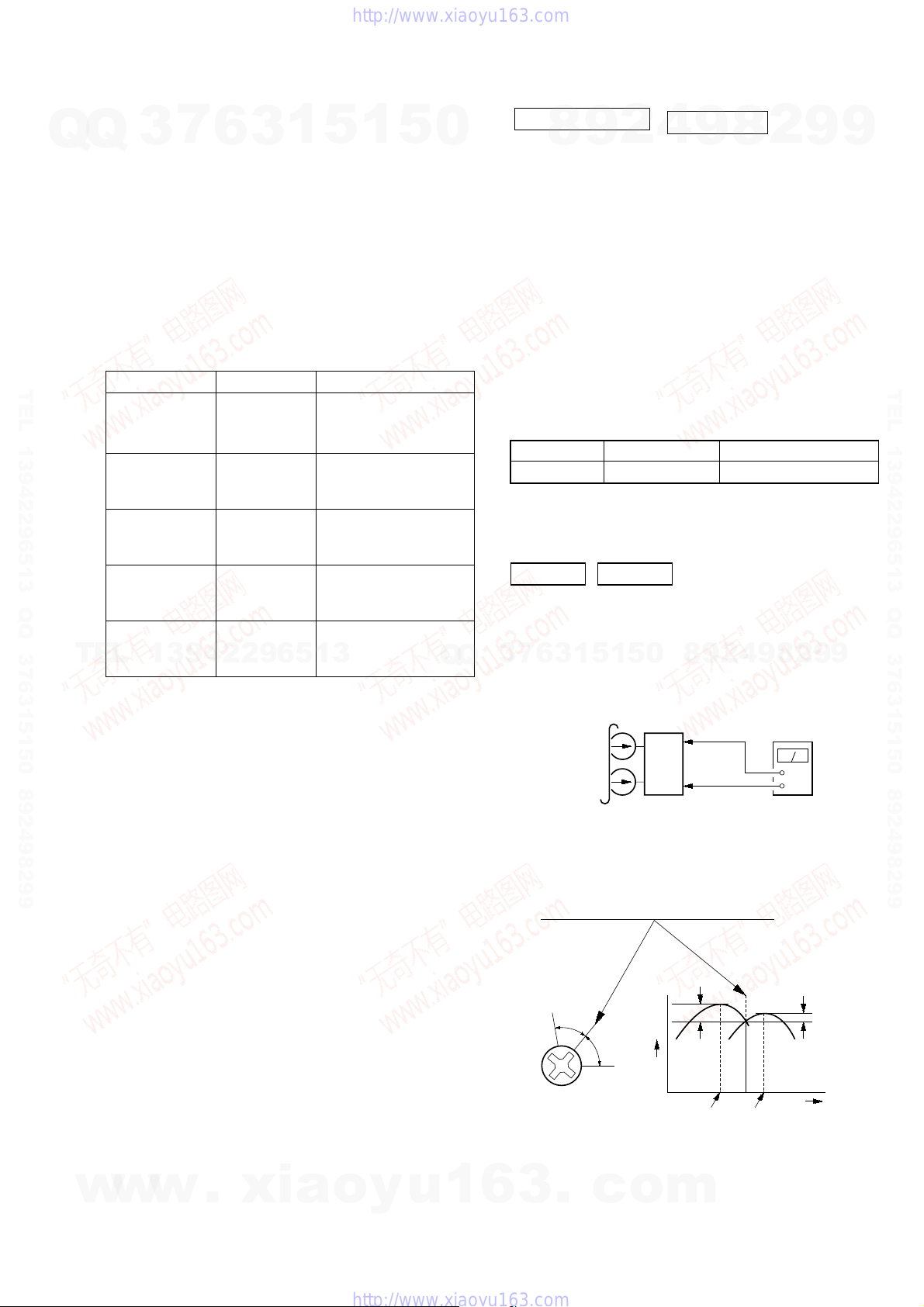
Torque Measurement
FWD CQ-102C 30 to 70 g • cm
FWD
back tension
REV CQ-102RC 30 to 70 g • cm
REV
back tension
FF/REW CQ-201B 49 to 170 g • cm
TEL
7
3
swab:
record/playback heads pinch rollers
erase head rubber belts
capstan idlers
demagnetizer.
the parts adjusted.
supply voltage unless otherwise noted.
Mode Torque meter Meter reading
6
13942296513
1
5
1
3
2.9m N • m to 6.9m N • m
(0.42 – 0.97 oz • inch)
0.15m N • m to 0.59m N • m
CQ-102C 2 to 6 g • cm
(0.03 – 0.08 oz • inch)
2.9m N • m to 6.9m N • m
(0.42 – 0.97 oz • inch)
0.15m N • m to 0.59m N • m
CQ-102RC 2 to 6 g • cm
(0.03 – 0.08 oz • inch)
4.8m N • m to 16.7m N • m
(0.68 – 2.36 oz • inch)
5
0
Q
Q
DECK SECTION
1. Demagnetize the record/playback head with a head
2. Do not use a magnetized screwdriver for the adjustments.
3. After the adjustments, apply suitable locking compound to the
4. The adjustments should be performed with the rated power
5. The adjustments should be performed in the order given in
6. The adjustments should be performed for both L-CH and R-
7. Switches and controls should be set as follows unless otherwise
•Test Tape
P-4-A100 10 kHz, –10 dB Azimuth Adjustment
RECORD/PLAYBACK HEAD AZIMUTH ADJUST-MENT
DECK A DECK B
Note: Perform this adjustments for both decks
Procedure:
1. Mode: Playback
7
3
SECTION 6
ELECTRICAL ADJUSTMENTS
2
9
8
demagnetizer.
parts adjust.
supply voltage unless otherwise noted.
this service manual. (As a general rule, playback circuit
adjustment should be completed before performing recording
circuit adjustment.)
CH.
specified.
Tape Signal Used for
0
5
1
5
1
3
6
9
8
9
2
0 dB=0.775 V
4
8
4
2
9
8
9
2
9
9
9
TEL 13942296513 QQ 376315150 892498299
w
w
w
.
xia
2. Turn the adjustment screw and check output peaks. If the peaks
do not match for L-CH and R-CH, turn the adjustment screw
so that outputs match within 1dB of peak.
Output
level
o
within
1dB
L-CH
peak
m
R-CH
peak
within
1dB
Screw
position
23
L-CH
peak
R-CH
Screw
position
o
y
u
1
6
3
.
peak
c
HCD-GN1000D
)
e
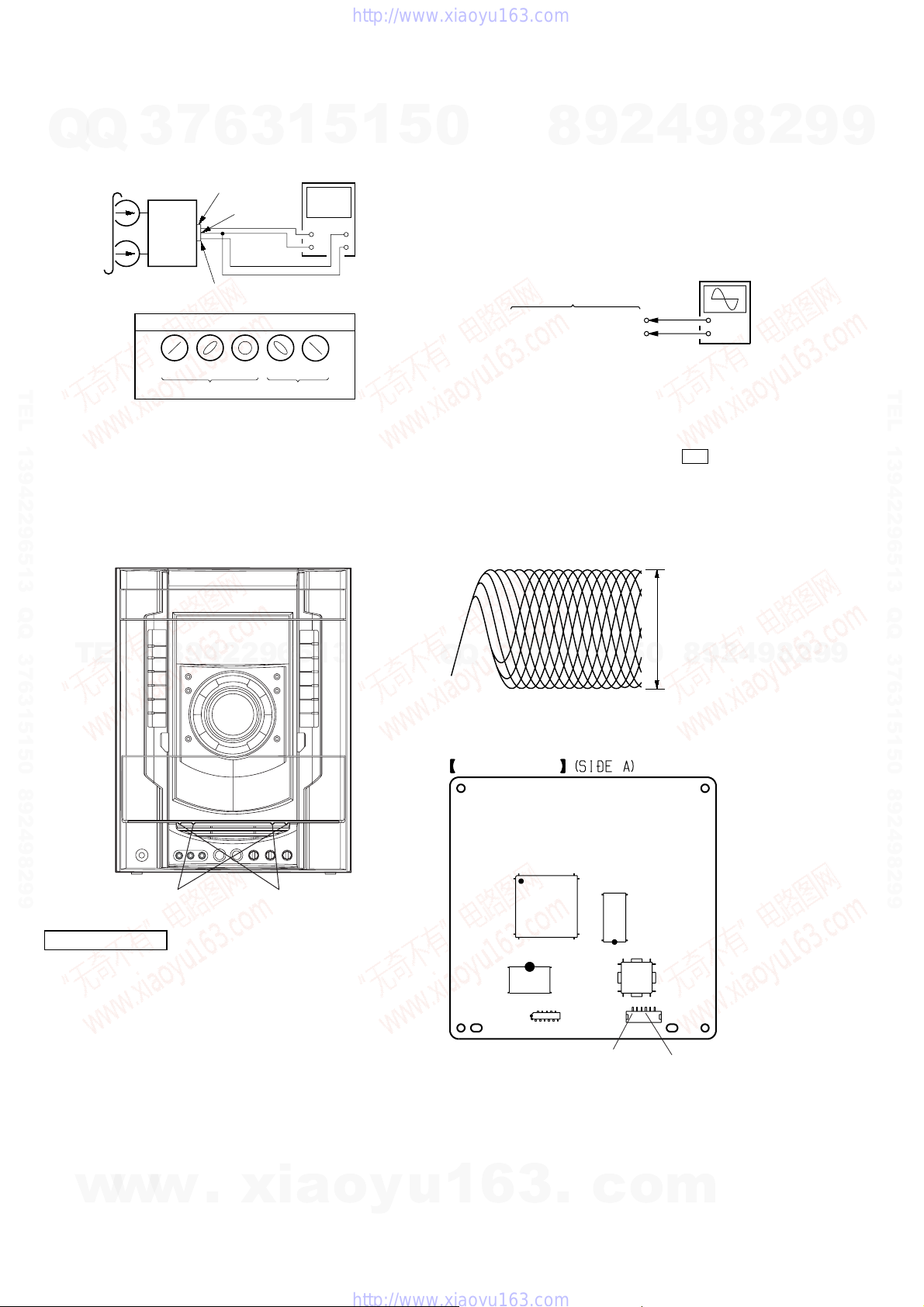
3. Mode: Playback
7
Q
Q
TEL 13942296513 QQ 376315150 892498299
4. After the adjustments, apply suitable locking compound to
the pats adjusted.
Adjustment Location: Playback Head (Deck A).
3
test tape
P-4-A100
(10 kHz, –10 dB)
L-CH
set
R-CH
in phase
6
MAIN
board
CN510
pin
1
pin
L
R
pin
3
waveform of oscilloscope
45
°
90
good
Record/Playback/Erase Head (Deck B).
3
2
°
135
1
°
wrong
5
oscilloscop
H
V
180
°
1
5
Note: When the BASE UNIT is replaced, perform the mirror time
0
adjustment and IOP measurement
(Refer to page 20 of the TEST MODE).
[RFMON Level Check]
Connection:
CN105 pin 6 (RFMON)
CN105 pin
Procedure:
1. Connect an oscilloscope to CN105 pin 6 (RFMON) and
CN105 pin 3 (GND) on the DMB15 board.
2. Turn the power on.
3. Set the test disc (DVD: HLX-503 (NTSC) or HLX-504 (PAL),
CD: YEDS-18) on the tray and press Y button to playback.
4. Confirm that oscilloscope waveform is clear and check
RFMON signal level is correct or not.
Note: A clear RFMON signal waveform means that the shape “◊” can be
clearly distinguished at the center of the waveform.
RFMON signal waveform
9
8
DMB15 board
3
(GND)
2
4
VOLT/DIV: 200 mV
TIME/DIV: 500 ns
8
9
oscilloscope
+
–
2
9
9
TEL 13942296513 QQ 376315150 892498299
TEL
DVD SECTION
[TEST DISC LIST]
Use the following test disc on test mode.
• CD: YEDS-18 (PART No. 3-702-101-01)
• DVD (SL)
NTSC HLX-503 (PART No. J-6090-069-A)
PAL HLX-506 (PART No. J-6090-077-A)
• DVD (DL)
NTSC HLX-501 (PART No. J-6090-071-A)
w
PAL HLX-507 (PART No. J-6090-078-A)
13942296513
forward
PATD-012 (PART No. 4-225-203-01)
HLX-504 (PART No. J-6090-088-A)
HLX-505 (PART No. J-6090-089-A)
w
w
.
reverse
or
or
or
xia
o
y
5
1
3
6
7
3
Q
Q
Checking Location: DMB15 board (Side A)
DMB15 BOARD
IC104
IC102
IC101
u
1
CN106
CN105 pin 6 (RFMON)
6
3
.
CN105
c
0.57 to 1.1 Vp-p (CD)
0
5
1
IC201
6
1
CN105 pin 3 (GND
o
level: 0.58 to 1.23 Vp-p (DVDSL)
9
2
8
9
4
2
9
8
m
9
24
SECTION 7
CD-SW board
TRANS board
PA board
SURROUND board
EFFECTOR board
SWITCHING POWER
TUNER PACK
PRIMARY board
VIDEO board
KARAOKE board
DMB15 board
d
DIAGRAMS
HCD-GN1000D
For Schematic Diagrams.
Q
TEL 13942296513 QQ 376315150 892498299
Q
Note:
• All capacitors are in µF unless otherwise noted. (p: pF)
50 V or less are not indicated except for electrolytics and
tantalums.
• All resistors are in Ω and 1/
specified.
•%: indicates tolerance.
• f : internal component.
• 2 : nonflammable resistor.
• 5 : fusible resistor.
Note:
The components identified by mark 0 or dotted line
with mark 0 are critical for safety .
Replace only with part number specified.
• C : panel designation.
• A : B+ Line.
• B : B– Line.
•Voltages and waveforms are dc with respect to ground under no-signal (detuned) conditions.
DMB15 and VIDEO boards
no mark : DVD PLAY
Other board
no mark : TUNER (FM/AM)
( ) : DVD PLAY
< > : TAPE PLAY
[ ] : TAPE REC
* : Impossible to measure
•Voltages are taken with a VOM (Input impedance 10 MΩ).
Voltage variations may be noted due to normal production
tolerances.
•Waveforms are taken with a oscilloscope.
Voltage variations may be noted due to normal production
tolerances.
T
E
• Circled numbers refer to waveforms.
• Signal path.
F : AUDIO
e : TUNER
k : TAPE PLAY (DECK A)
d : TAPE PLAY (DECK B)
G : REC (DECK B)
J : CD PLAY
N : MIC
c : DVD PLAY
L : VIDEO
E : Y
a : CHROMA
r : COMPONENT VIDEO
q : R, G, B
NOTE ON REPLACEMENT OF DMB15 BOARD
New part of EEPROM (IC103) on the DMB15 board cannot be used. Therefore, if the mounted
DMB15 board (A-1174-274-A or A-1193-178-A or A-1193-183-A or A-1193-188-A) is replaced,
exchange new EEPROM with that used before the replacement.
L
3
1
7
4
W or less unless otherwise
3
9
6
4
2
3
2
9
1
Note on Printed Wiring Boards.
Note:
• X : parts extracted from the component side.
• : Pattern from the side which enables seeing.
(The other layers' patterns are not indicated.)
Caution:
Pattern face side: Parts on the pattern face side seen from
(SIDE A) the pattern face are indicated.
Parts face side: Parts on the parts face side seen from
(SIDE B) the parts face are indicated.
• Indication of transistor.
C
Q
B
E
Q
B
CE
Q
B
CE
• Abbreviation
E2 : 120V AC Area in E model
E3 : 240V AC Area in E model
E12 : 220V-240V AC Area in E model
E15 : Iran model
6
EA : Saudi Arabia model
MY : Malaysia model
PH : Philippines model
SP : Singapore model
TH : Thai model
5
These are omitted.
These are omitted.
These are omitted.
5
1
3
1
5
0
Q
Q
3
• Circuit Boards Location
8
3
6
7
MOTOR (LD) board
PANEL board
1
9
5
1
SW board
2
0
5
SENSOR board
4
8
9
9
2
8
4
2
8
9
MOTOR (TB) board
2
DRIVER boar
9
9
9
TEL 13942296513 QQ 376315150 892498299
9
HCD-GN1000D
w
w
w
.
x
i
a
o
y
u
1
6
FUNCTION board
JOG board
3
2525
.
c
MIC board
o
MAIN board
m
HCD-GN1000D
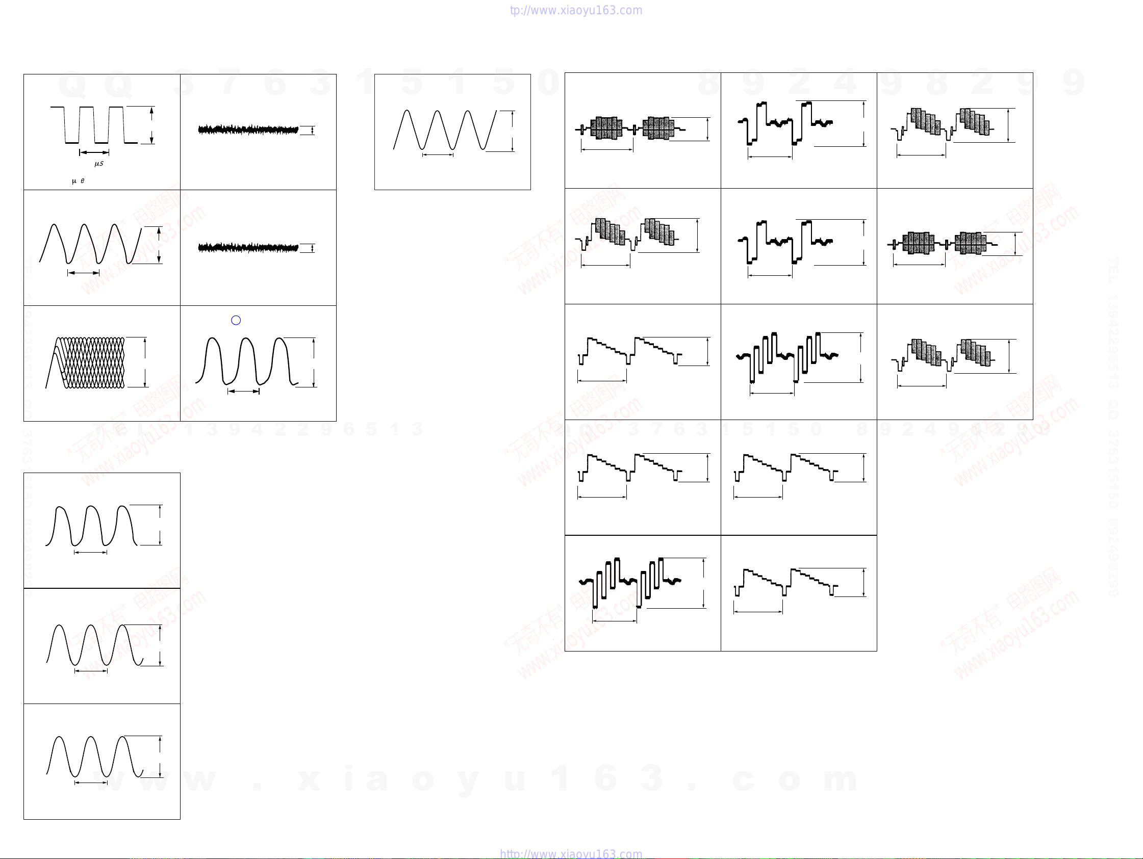
•Waveforms
– DMB15 Board –
1
IC301 9
2V/DIV, 0.1 msec/DIV
2
IC301 0
TEL 13942296513 QQ 376315150 892498299
2V/DIV, 20 nsec/DIV
3
IC102 6
Q
0.33
41 nsec
BICK
Q
m
sec
MCLK
DVDRFIP
3.3 Vp-p
4.0 Vp-p
4
IC102 ea
3
5
6
7
0.1V/DIV, 0.5 msec/DIV
IC102 es
0.1 V/DIV, 0.5 msec/DIV
IC102
FED
6
TEO
228
XTALO
3
0.1 Vp-p
0.1 Vp-p
1
– PANEL Board –
1
IC902 is
5
1V/DIV, 0.2 µsec/DIV
X OUT
250nsec
1
5
3.1 Vp-p
– VIDEO Board –
0
1
2
3
IC801 2
0.5 V/DIV, 20 µsec/DIV
IC801 4
0.5 V/DIV, 20 µsec/DIV
IC801 6
CIN
H
CVBSIN
H
YIN
1.0 Vp-p
1.3 Vp-p
8
6
IC801 qf
9
0.5 V/DIV, 20 µsec/DIV
7
IC801 qh
1 V/DIV, 20 µsec/DIV
8
IC801 qk
H
H
CRIN
2
CROUT
CBOUT
4
0.8 Vp-p
1.5 Vp-p
qa
IC801 wd
H
IC801 wh
H
IC800 7
8
9
1 V/DIV, 20 µsec/DIV
qs
1 V/DIV, 20 µsec/DIV
qd
CVBSOUT
C OUT
VOUT
2
2.6 Vp-p
2.0 Vp-p
9
9
TEL 13942296513 QQ 376315150 892498299
0.2V/DIV, 50 nsec/DIV
– MAIN Board –
1
IC401 qa
32 µsec
0.5 V/DIV, 10 µsec/DIV
2
IC401 qd
T
XC OUT
X-OUT
0.6 Vp-p
E
L
1.7 Vp-p
3.3 Vp-p
40 nsec
0.5V/DIV, 20 nsec/DIV
1
3
9
4
2
1.1 Vp-p
2
9
6
5
1
3
H
0.5 V/DIV, 20 µsec/DIV
Q
Q
4
IC801 0
H
0.5 V/DIV, 20 µsec/DIV
5
IC801 qs
0.5 V/DIV, 20 µsec/DIV
H
3
CYIN
CBIN
7
1.6 Vp-p
6
1.6 Vp-p
0.8 Vp-p
3
1 V/DIV, 20
1
5
1
9
IC801 w;
H
1 V/DIV, 20 µsec/DIV
0
IC801 wa
H
1 V/DIV, 20
H
µ
sec/DIV
µ
sec/DIV
5
CYOUT
YOUT
0
1.5 Vp-p
8
2.0 Vp-p
2.0 Vp-p
1 V/DIV, 20
2
9
H
µ
sec/DIV
4
9
8
2.6 Vp-p
2
9
9
200 nsec
1V/DIV, 50 nsec/DIV
3
CN503 2
20V/DIV, 5 µsec/DIV
HCD-GN1000D
E-HOT
11 µsec
w
60 Vp-p
w
w
.
x
i
a
o
y
u
1
2626
6
3
.
c
o
m
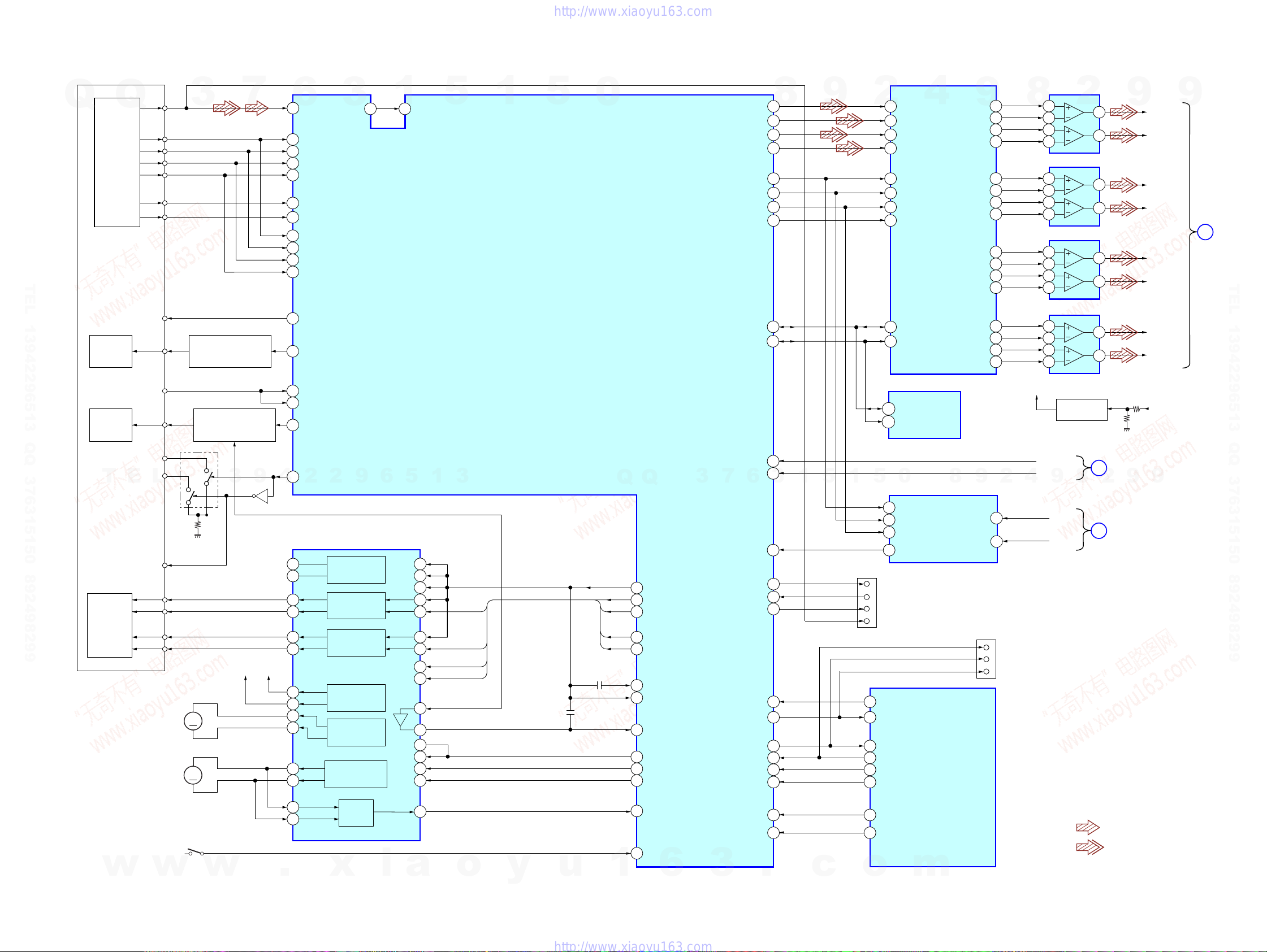
7-1. BLOCK DIAGRAM – RF SECTION –
Q102 (1/2)
Q102 (2/2)
3
7
9
Q103
4
6
DVDRFIP
6
DVDA
2
DVDB
3
DVDC
4
DVDD
5
19
TPI
18
TNI
8
NA
9
NB
10
MC
11
MD
29
V2O
23
LD01
20
MDI2
MDI1
21
LD02
22
MSW
50
2
2
3
OSP
9
3
AUTOMATIC POWER
CONTROL (FOR CD)
AUTOMATIC POWER
CONTROL (FOR DVD)
Q101
1
DVD LD
WR650
VR780
E
RF
A
B
C
D
F
E
VC
CD LD
PD
L
Q
TEL 13942296513 QQ 376315150 892498299
Q
DETECTOR
OPTICAL PICK-UP
BLOCK
(KHM-310CAB)
LASER
DIODE
(FOR CD)
LASER
DIODE
(FOR DVD)
T
1
252 253
6
5
OSN
1
5
1
IC102 (1/2)
CD/DVD RF AMP,
FOCUS/TRACKING ERROR AMP
DVD SYSTEM PROCESSOR
DIGITAL SERVO PROCESSOR
3
5
0
Q
Q
3
ASDATA0
ASDATA1
ASDATA2
ASDATQ3
ACLK
ABCK
ALRCK
XRST
SDA
SCL
VOICE/YUV7
SMSCK
6
7
8
217
218
219
222
215
214
213
220
103
102
206
208
3
1
9
5
1
2
14
15
16
13
10
9
17
8
20
19
5
6
5
4
SDTI1
SDTI2
SDTI3
SDTI4
MCLK
BICK
LRCK
PDN
IC301
D/A
CONVERTER
SDA
CSL
IC103
SDA
EEPROM
SCL
0
LOUT4+
ROUT4+
ROUT4-
LOUT1+
ROUT1+
ROUT1-
LOUT3+
ROUT3+
ROUT3-
LOUT2+
ROUT2+
ROUT2-
8
9
38
37
LOUT4-
33
32
2
LOUT1-
LOUT3-
LOUT2-
1
48
47
42
41
40
39
46
45
44
43
(IC3711,3731,3751,3771)
2
9
8
BIAS
XVOICE
SCORE
4
IC3771
3
2
5
6
IC3711
3
2
5
6
IC3751
3
2
5
6
IC3731
3
2
5
6
9
AMP
2
AMP
AMP
AMP
Q3801
BIAS
8
B
1
7
1
7
1
7
1
7
2
HCD-GN1000D
9
DM_L
DM_R
MB_FL
MB_FR
FC
SW(LEE)
MB_SL
MB_SR
AU+5V
MAIN
SECTION
(Page 30)
9
9
9
MAIN
SECTION
A
(Page 30)
TEL 13942296513 QQ 376315150 892498299
2AXIS
DEVICE
FOCUS/
TRACKING
COIL
w
MSW
FCS+
FCS–
TRK+
TRK–
M2
(SLED)
M1
(SPINDLE)
S1
(LIMIT)
w
MM
MM
w
REG02
SP+
SP–
FOCUS/TRACKING COIL DRIVER,
IC201
SPINDLE, SLED MOTOR DRIVER
42
NC
41
NC
36 48
37 1
35 3
34 4
REG01
32
31
SL–
30
SL+
29
27
28
46
47
.
BUFFER
FOCUS COIL
DRIVE
TRACKING COIL
DRIVE
SLED MOTOR
DRIVE
SLED MOTOR
DRIVE
SPINDLE MOTOR
DRIVE
BUFFER
x
i
9
12
43
10
13
42
40
21
19
20
22
45
a
VREFO
FOO
TRO
FMO
DMO
IOP
IOPMON
o
y
u
VREFO
FMO
FOO
DMO
TRO
1
30
38
42
37
41
245
246
40
211
210
170
47
176
VREFO
FMO
FOO
DND
TRO
RFRPDC
RFRPAC
IOPMON
MUTE123
MUTE
TSD M
SPFG
LIMSW
6
SPDATA/SMSDI
TXD
RXD
V2 REF0
PRST
IFCK
IFSDO
IFSDI
XIFCS
IFBSY
MIC/VSYNC
KRMOD/HSYNC
3
.
209
107
106
28
110
99
98
101
100
105
205
207
c
CN105
1
2
5
6
25
33
32
31
24
23
21
22
o
15
SCKI
11
BCK
10
LRCK
12
DOUT
TXD
RXD
V2REF0
RFMON
MTK-RESET
MTK-CLK
MTK-SOD
MTK-SIO
MTK-XIFCS
MTK-BUSY
MIC SSTATUS
KRMOD
m
IC3601
D/A
CONVERTER
(FOR CHECK)
IC401 (1/6)
SYSTEM
CONTROLLER
LIN
RIN
CN402
(1/3)
1
2
TXD1
RXD1
CLK1
LIN
RIN
(FOR CHECK)
SECTION
F
(Page 30)
• Signal Path
: CD PLAY
: DVD PLAY
MAIN
HCD-GN1000D
2727
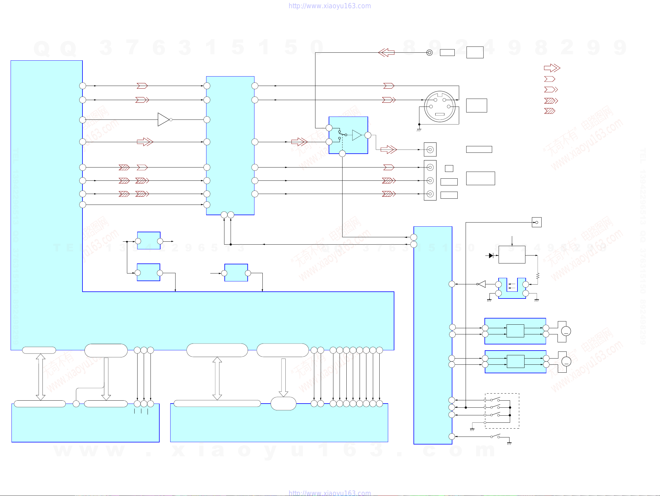
HCD-GN1000D
7-2. BLOCK DIAGRAM – VIDEO SECTION –
SW+5V
3
7
9
5
5
IC107
+3.3V
REG.
4
IC105
+3.3V
REG.
6
Q800
4
2
4
+3.3V
RF+3.3V
2
VDD
3
9
Q
TEL 13942296513 QQ 376315150 892498299
T
Q
YUV1
YUV2
DISC/X
YUY3
YUY4
YUY5
YUV6
WODE
E
194
196
168
198
200
202
203
49
L
3
1
1
VIDEO AMP, 75 DRIVER
6
2
9
4
10
12
14
25
6
SW+3.3V
YIN
CIN
I/P
CVBSIN
CYIN
CBIN
CRIN
SI
5
5
IC801
YOUT
COUT
VOUT
CYOUT
CBOUT
CROUT
MUTE1
MUTE2
3 13
1
3
IC106
+1.8V
1 3
REG.
1
21
26
23
20
18
16
AV SEL1
RF1.8V
DVDD18
VOUT
CYOUT
CBOUT
CROUT
5
0
VIDEO SELECT
3
1
Q
IC800
Q
2
7
VIDEO OUT SW
V MUTE
7
3
6
8
SYSTEM CONTROL
87
VIDEO-OUT-SW
VMUTE
88
1
3
J1102(1/2)
9
J801
C
J802
J800
IC401(2/6)
5
TSENS
VIDEO
21
PB/C
PR/C
1
43
Y
27
2
Y
B
R
5
VIDEO
4
INPUT
S VIDEO
OUT
VIDEO OUT
COMPONENT
VIDEO OUT
0
D505
EVER 4V
Q731
9
M+9V
+3.3V
9
8
REG.
Q523,524
IC731
TABLE SENSOR
3
4
2
1
2
8
CN402
(2/3)
4
D+3.3V
RTS1
9
2
: VIDEO
: Y
: CHROMA
: COMPONENT VIDEO
: R, G, B
(FOR CHECK)
8
• Signal Path
2
9
9
9
TEL 13942296513 QQ 376315150 892498299
9
HIGHA0-7
IOA0-7, IOA18-IOA20
AB0 – AB7
81-84,86-88,91
HD0 – HD7
29,31,33,35,38,40,42,44 25-16, 10-1, 40,12,48
DQ0 – DQ7
FLASH ROM
w
HCD-GN1000D
A16, A17
53-61, 67-72, 74-76,
78, 89, 92, 93
A0
A0 – A21DQ15/A-1
IC101
w
A0 – A21
A1-A21
w
IC102(2/2)
DVD SYSTEM PROCESSOR
IOCS
IOWA
IOUE
77
79
66
2645
28OE11
CE
WE
.
RD0 – RD15
125-123, 121, 120, 118,
117, 115, 135, 133-128, 126
2,4,5,7,8,10,11,13,42,44,45,47,48,50,51,53
RD0 – RD15
x
i
a
o
RA0 – RA11
146, 147, 149-151,
158-160, 162, 164-166
22-26,
29-35
RA0 – RA11
IC104
SDRAM
y
u
RCLK
RCS
RWE
RAS
16
140
18
RWE
139
17
RAS
CAS
15
CAS
BA0
BA1
142
38
DRCLK
138
19
RCS
6
143
145 156 113 137 157
20
21
BS0
BS1
1
2828
KDQM0
KDQM1
39
37
DQM0
DQM1
3
CLE
DRCKLE
.
LOG-POS
LOG-NEG
TBL-POS
TBL-NEG
EJECTSW
c
E-1
E-2
E-3
38
39
36
37
35
34
28
26
o
FIN
7
RIN
9
FIN
7
RIN
9
m
IC701
LD MOTOR DRIVER
MOTOR
DRIVE
MOTOR
DRIVE
IC712
TBL MOTOR DRIVER
S711
ROTARY
ENCODER
S751
(OPEN)
OUT2
OUT1
OUT2
OUT1
2
4
2
4
M
M751
(TABLE LOADING)
M741
M
(TABLE)
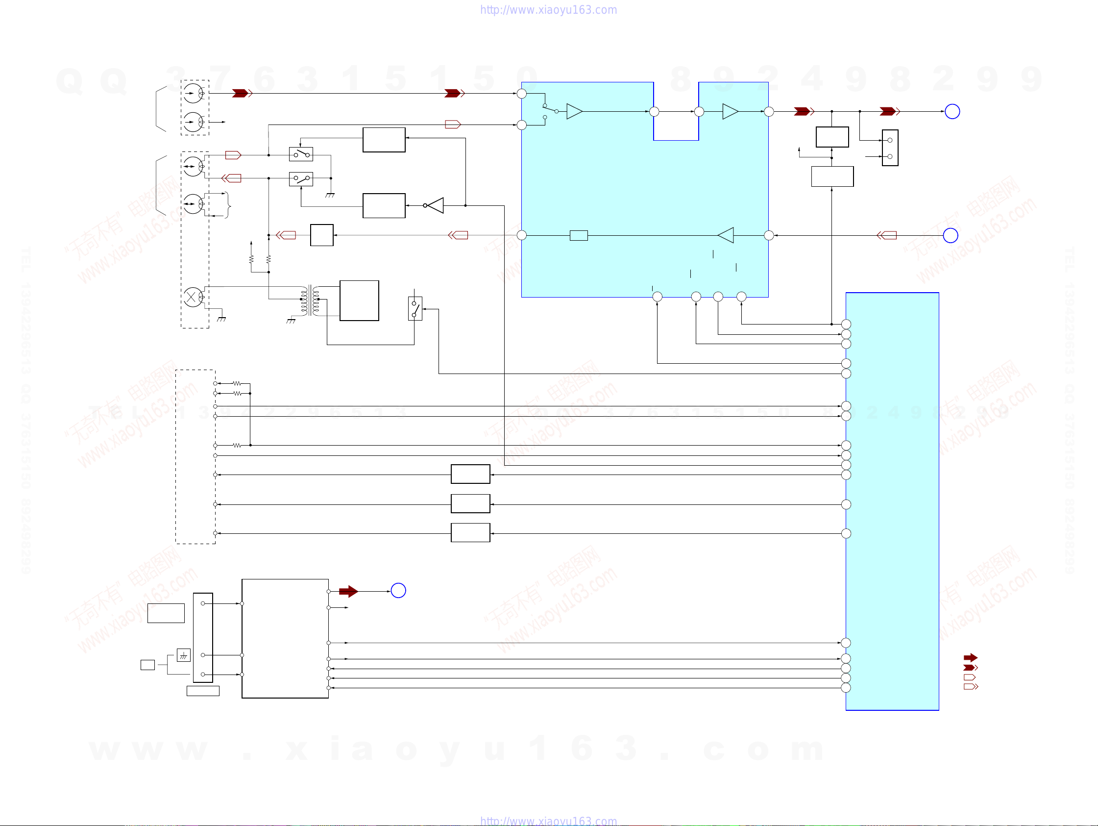
7-3. BLOCK DIAGRAM – TAPE/TUNER SECTION –
DECK-A
DECK-B
7
R-CH
R-CH
R-CH
6
3
Q325
Q321, 322
T301
Q
TEL 13942296513 QQ 376315150 892498299
Q
HEAD
REC/PB
HEAD
3
L – CH
PB
R – CH
L – CH
R – CH
ERASE
HEAD
1
BIAS
TRAP
BIAS OSC
Q370
5
SWITCH
DRIVE
Q382, 383
SWITCH
DRIVE
Q377, 379
BIAS+9V
1
Q381
Q378,380
5
AIN1
0
32
34
BIN1
REC-OUT1
21
A
B
EQ
EQ OUT1
28 27 26
DECK A/B SELECT
PB/REC EQUALIZER AMP
IC301
A/B
13 11 15 14
8
9
TAI1
ALC ON/OFF
REC MUTE ON/OFF
2
PB OUT1
REC IN1
MUTE ON/OFF
HCD-GN1000D
TC-PB-L
TEST
CONNECTOR
REC-OUT-L
2
D
C
9
MAIN
SECTION
(Page 30)
MAIN
SECTION
(Page 30)
9
TEL 13942296513 QQ 376315150 892498299
4
R-CH
MUTE DRIVE
24
9
MUTE
Q106
R-CH
Q509, 510
(DVD/TAPE MECHANISM CONTROL)
8
CN510
L
R
SYSTEM CONTROL
IC401(3/6)
T
E
L
FM 75
COAXIAL
TAPE
MECHANISM
BLOCK
REC(REV)
REC(FWD)
B PULSE
1
3
A PULSE
BHALF
AHALF
ATRGM+
BTRGM+
CAP M+
CN509
9
4
2
FM/AM TUNER UNIT
FM ANT
2
9
ST-L
ST-R
6
5
R-CH
1
ST-L
3
E
MAIN
SECTION
(Page 30)
Q340, 343
A TRIG
DRIVE
Q342, 345
B TRIG
DRIVE
Q341,344
CAP MOTOR
DRIVE
Q
Q
3
7
6
3
1
5
1
5
0
8
71
TC-MUTE
54
REC-MUTE
56
ALC
55
PB-A/B
REC BIAS
52
90
B-SHUT
A-SHUT
89
9
B-HALF
91
A-HALF
47
53
TC-RELAY
48
A-TRIG
49
B-TRIG
CAPM-CONT
50
2
4
9
8
2
9
9
HCD-GN1000D
w
AM
w
ANTENNA
w
.
AM ANT
AM ANT
TUNED
ST-DIN/MC-DOUT
ST-DOUT
ST-CLK
ST-CE
x
i
a
o
y
u
1
6
3
2929
.
c
o
m
1
2
5
3
6
TUNED
ST-DOUT
ST-DIN
ST-CLK
ST-CE
• R-CH is omitted due to same as L-CH.
• Signal Path
: TUNER
: TAPE PLAY (DECK A)
: TAPE PLAY (DECK B)
: RECORD (DECK B)
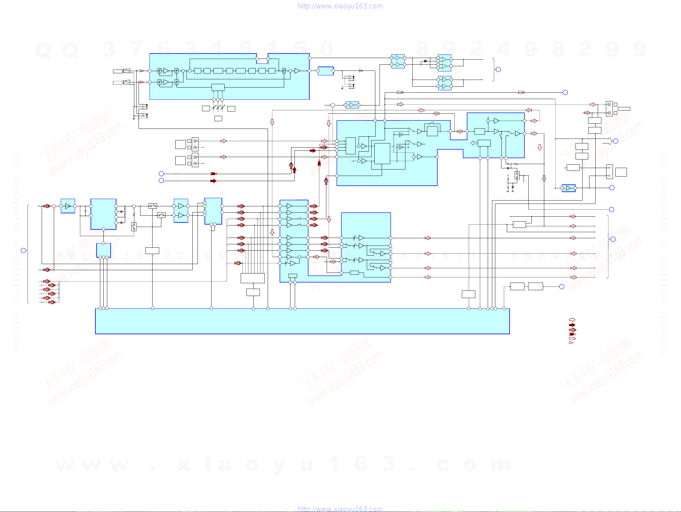
HCD-GN1000D
7-4. BLOCK DIAGRAM – MAIN SECTION –
J1101(1/3)
MIC 2
J1100(1/3)
MIC 1
9
10
11
12
3
7
+
Q1502
9
MC1P
15
MC2P
16
J1100(2/3)
J1101(2/3)
TAPE/TUNER
SECTION
(Page 29)
TAPE/TUNER
SECTION
(Page 29)
Q1508
BUFFER
Q1509, 1510
4
86
EFFECTOR-FLANGER
6
ALC
ALC
C
E
Q1506
SELECT
TC-PB-L
2
3
MIC VOL
TV/SAT
ST-L
IC1505
MIXER L/R
5
3
2
MIC
VOL
AUDIO
VIDEO
INPUT
AUDIO
IN
+ ++
PRE
ADC DAC S/HDELAY
LPF
RV1101
MIC 2
LEVEL
J201
L
R
R-CH
L
R-CH
R
J1102(2/2)
IC1506
SELECTOR CCT
1
9
12
11
6
0Y
OX
3X
7
13
Q
Q
3
TEL 13942296513 QQ 376315150 892498299
RF
SECTION
(Page 27)
IC1500
MIXER
DM-L
A
+
T
DM-R
MB_FL
MB_FR
FC
MB_SL
MB_SR
SW (LFE)
1
3
E
IC1503
MULTIPLEXER
L
2
3
DIGITAL DELAY
LPF1OUT
IC1501
CLOCK
14
3
COM
AB
10 911
19
EFFECTOR S143EFFECTOR S2
EFFECTOR S0
LPF2OUTLPF1IN
OP2OUT
A
C
44
LPF2IN
OP2IN
1
1
ADPCM
ENCODE
VOLUME
CONTROL
VOL1
VOL2
5 6 7
RV1102
MIC 1
LEVEL
Y COM3Y
X COM
BA
9 10
5
18
EFFECTOR SELECT
VOL3
34
13
IC1100
DIGTAL
ECHO
RV1100
LEVEL
DM_L
DM_R
FC
SW (LFE)
ECHO
MB_FL
MB_FR
MB_SL
MB_SR
1
8
RECB1
SURROUND OR
DPL BUFFER
IC2000
31
57
25
31
30
29
6
7
28
27
26
22
8
D2004
-2008
C
A
B
C
A
B
+
3
5
ADPCM
DECODE
3
Q200,202-204,
250,252-254
1
AD IN
MUTE DRIVE
25
23
POST
LPF
MUTE
Q507,508
77 85 79 80
MIC DETECT
DVD A MUTE
ECHO
VOL
37
40
41
2
13
6
10
15
14
DATA CLOCK
17 18
81 82
VOL IC DATA
5
+
I/F
VOL IC CLK
MCO
POOUT
0
29
IC1101
MIC AMP
2
29
R-CH
38
39
R-CH
34
32
R-CH
12
5
9
24
R-CH
IC401(4/6)
SYSTEM CONTROL
MIC OUT
7
IC304 (1/2)
MUSIC L+R
21
+
INPUT SELECT SWITCH,
GRAPHIC EQUALIZER CONTROL,
ELECTRICAL VOLUME
SAT-L
4
DVD1
INPUT
5
TC-L
SELECT
3
ST-L
SWITCH
6
VIDEO-L
7
R-CH
SUR-L
42
11
4
3
8
Q
Q
7
23
AMP
IC101
LPF
J1100(3/3)
J1101(3/3)
+
+
SURROUND
VOL CONTROL
IC201
2
MIC
3
R-CH
BASS &
TREBLE
SAOUT
1
MID/
19
IC2001
9
3
1
2
5
7
6
IC2002
31
67
LINK-L
TOUT1
14 15
5
1
COMMAND
MUTE DRIVE
2
VOLIN1
5
Q505,506
LINE MUTE
VOLUME
CONTROL
INTERFACE
DATA
SCORE
XVOICE
R-CH
+
CPU
CLK
22 1621
0
AUDIO IC CLK
AUDIO IC DATA
4
B
46
8376
AUDIO-OUT-SW
ANALOG IN MUTE
(Page 27)
BB-A1
RF
SECTION
BB-B1
17
A+9V
R-CH
75
SW MUTE
Q514, 564
8
MUTE DRIVE
SWOUT
MUTE
Q511
OUT1
Q101
R-CH
9
24
18
9
MUTE DRIVE
Q519,512,515
2
TAPE/TUNER
D
SECTION
(Page 29)
4V REG.
Q323
IC304 (2/2)
SPEANA IN
AMP
6
9
DISPLAY/POWER
SECTION
J
(Page 32)
2
R-CH
MUTE
Q117
MUTE DRIVE
Q516, 517
7
8
MUTE
Q206
MUTE DRIVE
Q521, 522
2
8
REC-OUT-L
A +9V
R-CH
4
AC DETECT
• R-CH is omitted due to same as L-CH.
• Signal Path
: AUDIO
: TUNER
: DVD PLAY
: TAPE PLAY
: REC (DECK B)
: MIC
R-CH
D +4V
L+R
(SPEANA)
SPEANA
DBFB F/B
F-R
F-L
LINE-MUTE
CENTER
SL
SR
SW OUT
9
J202
LIN
RIN
J103
G
I
H
9
L
AUDIO OUT
R
RF
SECTION
F
(Page 27)
D-LIGHT
SYNC
OUT
DISPLAY/POWER
SECTION
(Page 32)
AMP
SECTION
(Page 31)
AMP
SECTION
(Page 31)
9
9
TEL 13942296513 QQ 376315150 892498299
HCD-GN1000D
w
w
w
.
x
i
a
o
y
u
1
6
3030
3
.
c
o
m
 Loading...