

Sony HCD-FLX7D, HCD-FLX5D Service Manual
HCD-FLX5D/FLX7D
Q
Q
3
7
6
3
1
5
1
5
0
SERVICE MANUAL
Ver 1.1 2004.08
TEL 13942296513 QQ 376315150 892498299
HCD-FLX5D/FLX7D are the amplifier, DVD player,
tape deck and tuner section in DHC-FLX5D/FLX7D .
Photo: HCD-FLX7D
Model Name Using Similar Mechanism NEW
DVD
Section
TAPE
Section
DVD Mechanism Type CDM53N-DVBU14
Base Unit Name DVBU14
Optical Traverse Unit Name DBU-1
Model Name Using Similar Mechanism NEW
8
9
2
4
9
8
2
9
E Model
HCD-FLX5D/FLX7D
Australian Model
HCD-FLX5D
9
TEL 13942296513 QQ 376315150 892498299
TEL
13942296513
Amplifier section:
The following measured at AC 127, 220, 240 V,
50/60 Hz (Saudi Arabian model only)
The following measured at AC 120, 220, 240 V,
50/60 Hz (except for Saudi Arabian model)
MULTI mode
DIN power output at stereo mode (rated)
45 + 45 watts
(8 ohms at 1 kHz, DIN)
Continuous RMS power output (reference)
Front speaker: 60 + 60 watts
(8 ohms at 1 kHz, 10%
THD)
Center speaker: 60 watts
(16 ohms at 1 kHz, 10%
THD)
Rear speaker: 60 + 60 watts
(8 ohms at 1 kHz, 10%
THD)
Sub woofer: 100 watts
(8 ohms at 100 Hz, 10%
THD)
5
1
3
6
7
3
Q
Q
SPECIFICATIONS
2.1CH mode
DIN power output at stereo mode (rated)
Continuous RMS power output (reference)
Front speaker: 120 + 120 watts
Sub woofer: 240 watts
Inputs
VIDEO/SAT IN L/R (phono jacks):
OPTICAL DIGITAL IN (Square optical connector
jacks, rear panel) :
wavelength ——
MIC (phone jack) : sensitivity 1 mV,
70 + 70 watts
(8 ohms at 1 kHz, DIN)
(8 ohms at 1 kHz, 10%
THD)
(8 ohms at 100 Hz, 10%
THD)
voltage 250 mV/450mV,
impedance 47 kilohms
impedance 10 kilohms
2
8
9
4
2
9
8
0
5
1
Outputs
VIDEO OUT L/R (phono jacks):
VIDEO OUT: 1 Vp-p, 75 ohms
S VIDEO OUT: Y: 1 Vp-p, 75 ohms
COMPONENT VIDEO OUT:
PHONES (stereo mini jack):
FRONT L/R: Use only the supplied
REAR L/R: Use only the supplied
CENTER: Use only the supplied
S.WOOFER: Use only the supplied
voltage 250 mV,
impedance 1 kilohms
C: 0.286Vp-p, 75 ohms
Y: 1 Vp -p, 75 ohm
B
: 0.7 Vp-p, 75 ohms
P
R
: 0.7 Vp-p, 75 ohms
P
accepts headphones of
8 ohms or more
speaker SS-FLX9
speaker SS-RS9
speaker SS-CT9
speaker SS-WG9
– Continued on next page –
9
9
w
w
w
9-877-739-02 Sony Corporation
2004H05-1 Audio Group
© 2004.08 Published by Sony Engineering Corporation
.
xia
o
y
u
1
6
3
.
c
DVD DECK RECEIVER
o
m
HCD-FLX5D/FLX7D
Disc player section
Laser Semiconductor laser
Q
Q
Frequency response DVD (PCM 48 kHz):
Signal-to-noise ratio More than 90 dB
Dynamic range More than 90 dB
Video color system format
OPTICAL DIGITAL OUT (Square optical
connector jack, rear panel)
TEL 13942296513 QQ 376315150 892498299
wavelength 660 nm
Tape player section
Recording system 4-track 2-channel stereo
Frequency response 50 − 13,000 Hz (±3 dB),
7
3
(DVD and SA-CD:
λ=650 nm,
CD: λ=780 nm)
Emission duration:
continuous
2 Hz − 22 kH
= (±1 dB)
CD: 2 Hz − 20 kHz =
(±1 dB)
NTSC, PAL
using Sony TYPE I
cassette
6
3
Tuner section
FM stereo, FM/AM superheterodyne tuner
1
5
1
5
0
FM tuner section
Tuning range 87.5 − 108.0 MHz
Antenna FM lead antenna
Antenna terminals 75 ohm unbalanced
Intermediate frequency 10.7 MHz
AM tuner section
Tuning range
Latin American model: 530 − 1,710 kHz
Saudi Arabian model: 531 − 1,602 kHz
Other models: 530 − 1,710 kHz
Antenna AM loop antenna
Antenna terminals External antenna
Intermediate frequency 450 kHz
(50-kHz step)
(with the tuning
interval set at 10 kHz)
531 − 1,710 kHz
(with the tuning
interval set at 9 kHz)
(with the tuning
interval set at 9 kHz)
(with the tuning
interval set at 10 kHz)
531 − 1,602 kHz
(with the tuning
interval set at 9 kHz)
terminal
General
Power requirements
9
8
Saudi Arabian model: 120 − 127 V, 220 V or
Australian model: 230 − 240 V AC,
Thailand model: 220 V AC, 50/60 Hz
Korean model: 220 V AC, 60 Hz
Other models: 120 V, 22 0 V or
Power consumption 425 watts
Dimensions (w/h/d) Approx. 235 × 435 ×
Mass Approx. 15.0 kg
Design and specifications are subject to change
without notice.
2
4
8
9
230 − 240 V AC,
50/60 Hz
Adjustable with
voltage selector
50/60 Hz
230 − 240 V AC,
50/60 Hz
Adjustable with
voltage selector
420 mm
2
9
9
TEL 13942296513 QQ 376315150 892498299
Notes on chip component replacement
• Never reuse a disconnected chip component.
• Notice that the minus side of a tantalum capacitor may be dam-
TEL
aged by heat.
Flexible Circuit Board Repairing
• Keep the temperature of the soldering iron around 270 ˚C dur-
ing repairing.
• Do not touch the soldering iron on the same conductor of the
circuit board (within 3 times).
• Be careful not to apply force on the conductor when soldering
or unsoldering.
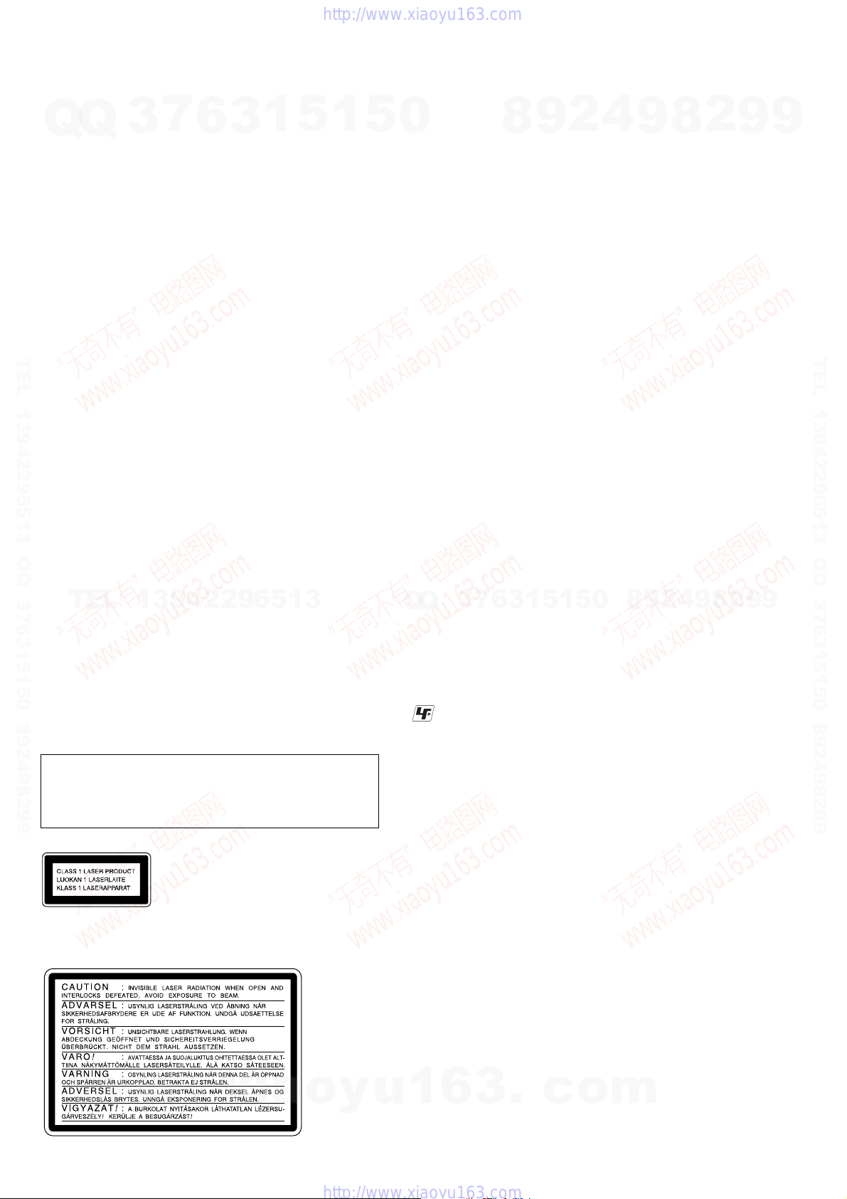
CAUTION
Use of controls or adjustments or performance of procedures
other than those specified herein may result in hazardous radiation exposure.
The following caution label is located inside the apparatus.
13942296513
This appliance is classified as
a CLASS 1 LASER product.
The CLASS 1 LASER
PRODUCT MARKING is
located on the rear exterior.
8
9
4
2
9
8
0
5
1
5
1
3
6
7
3
Q
Q
UNLEADED SOLDER
Boards requiring use of unleaded solder are printed with the leadfree mark (LF) indicating the solder contains no lead.
(Caution: Some printed circuit boards may not come printed with
the lead free mark due to their particular size)
: LEAD FREE MARK
Unleaded solder has the following characteristics.
• Unleaded solder melts at a temperature about 40 ˚C higher than
ordinary solder.
Ordinary soldering irons can be used but the iron tip has to be
applied to the solder joint for a slightly longer time.
Soldering irons using a temperature regulator should be set to
about 350 ˚C.
Caution: The printed pattern (copper foil) may peel away if the
heated tip is applied for too long, so be careful!
• Strong viscosity
Unleaded solder is more viscou-s (sticky, less prone to flow)
than ordinary solder so use caution not to let solder bridges occur such as on IC pins, etc.
• Usable with ordinary solder
It is best to use only unleaded solder but unleaded solder may
also be added to ordinary solder.
2
9
9
2
w
w
w
.
xia
SAFETY-RELATED COMPONENT WARNING!!
COMPONENTS IDENTIFIED BY MARK 0 OR DOTTED
LINE WITH MARK 0 ON THE SCHEMATIC DIA GRAMS
AND IN THE PARTS LIST ARE CRITICAL TO SAFE
o
y
u
OPERATION. REPLACE THESE COMPONENTS WITH
1
6
SONY PARTS WHOSE PART NUMBERS APPEAR AS
SHOWN IN THIS MANUAL OR IN SUPPLEMENTS PUBLISHED BY SONY.
3
.
c
o
m
HCD-FLX5D/FLX7D
Q
TEL 13942296513 QQ 376315150 892498299
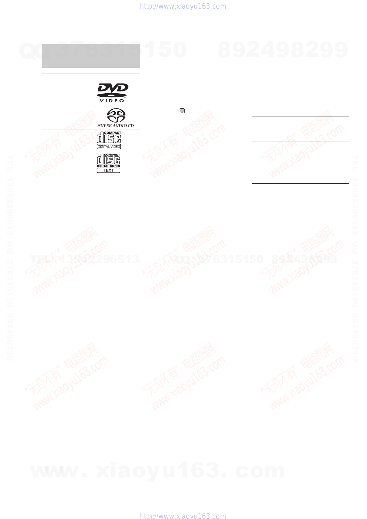
This system can play the
Q
following discs
Format of discs Disc logo
DVD VIDEO*
Super Audio CD**
VIDEO CD
Music CD
*The “DVD VIDEO” logo is a trademark.
**DHC-FLX7D only
Discs that this system cannot
play
• CD-ROMs (PHOTO CDs included)
• All CD-Rs other than music and VCD
format CD-Rs
• Data part of CD-Extras
• DVD-ROMs
• DVD Audio discs
Note
Some CD-Rs/CD-RWs or DVD-Rs/DVD-RWs
TEL
cannot be played on this system depending upon the
format or the recording quality or physical condition
of the disc, or the characteristics of the recording
device.
Furthermore, the disc will not play if it has not been
correctly finalized. For more information, see the
operating instructions for the recording device.
3
7
6
3
1
13942296513
5
1
5
0
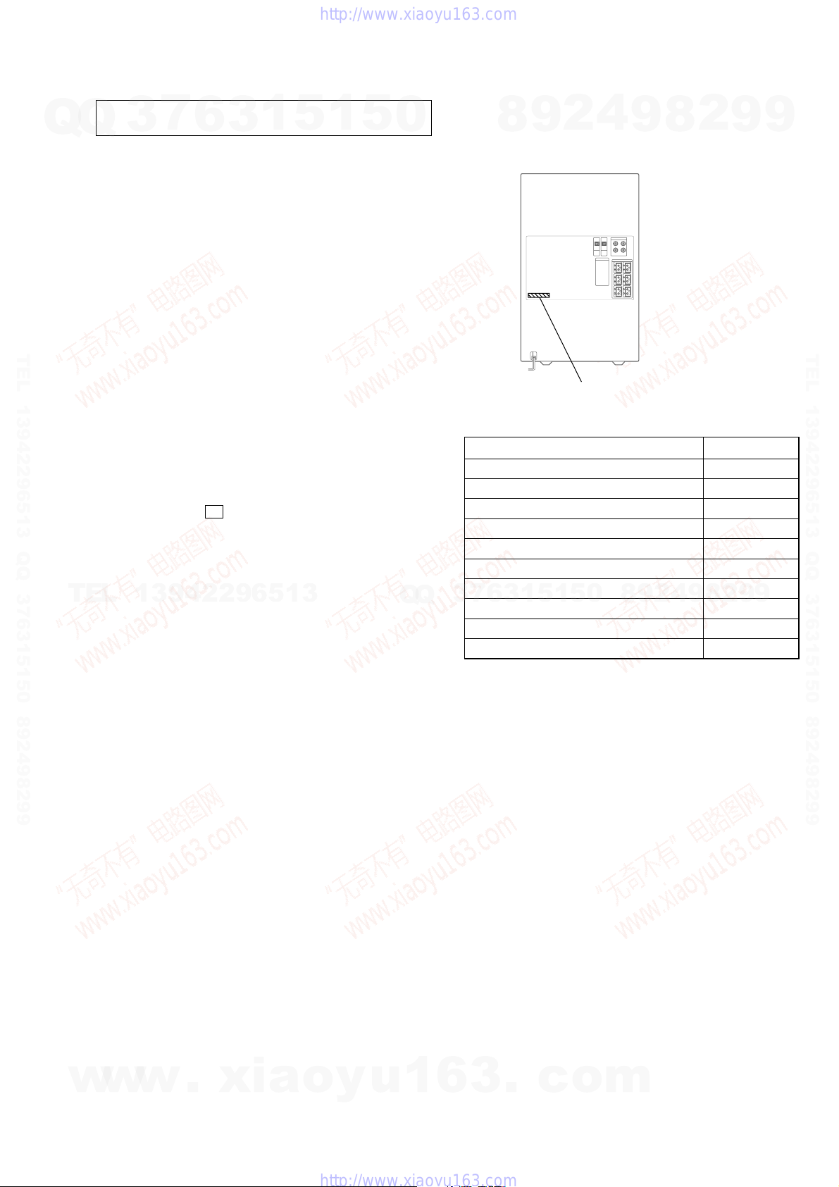
Region code of DVDs you can
play on this system
You r system has a region code printed on the
back of the unit and will only play DVDs
labeled with identical region code.
DVDs labeled will also be played on this
system.
If you try to play any other DVD, the
message “Playback prohibited by area
limitations.” will appear on the TV screen.
Depending on the DVD, no region code
indication may be labeled even though
playing the DVD is prohibited by area
restrictions.
The region code is located below the
COMPONENT VIDEO OUT jacks on the
rear panel.
Note on playback operations of
DVDs and VIDEO CDs
Some playback operations of DVDs and
VIDEO CDs may be intentionally set by
software producers. Since this system plays
DVDs and VIDEO CDs according to the disc
contents the software producers designed,
some playback features may not be available.
Also, refer to the instructions supplied with
the DVDs or VIDEO CDs.
Q
ALL
Q
3
7
8
6
3
9
1
4
2
Note on PBC (Playback Control)
(VIDEO CDs)
This system conforms to Ver. 1.1 and Ver. 2.0
of VIDEO CD standards. You can enjoy two
kinds of playback depending on the disc type.
Disc type You can
VIDEO CDs
without PBC
functions
(Ve r. 1.1 discs)
VIDEO CDs
with PBC
functions
(Ve r. 2.0 discs)
Copyrights
This product incorporates copyright protection
technology that is protected by U.S. patents
and other intellectual property rights. Use of
this copyright protection technology must be
authorized by Macrovision, and is intended for
home and other limited viewing uses only
unless otherwise authorized by Macrovision.
Reverse engineering or disassembly is
prohibited.
0
5
1
5
9
Enjoy video playback (moving
pictures) as well as music.
Play interactive software using
menu screens displayed on the TV
screen (PBC Playback), in addition
to the video playback functions of
Ver. 1.1 di scs. Moreover, you can
play high-resolution still pictures,
if they are included on the disc.
2
9
8
8
4
2
9
8
9
2
9
9
TEL 13942296513 QQ 376315150 892498299
9
w
w
w
.
xia
o
y
u
1
6
3
.
c
o
m
3

HCD-FLX5D/FLX7D
TABLE OF CONTENTS
7
Q
Q
1. SERVICING NOTES ................................................ 5
2. GENERAL
Location of Controls ....................................................... 9
Setting the Clock ............................................................. 10
3. DISASSEMBLY
3-1. Disassembly Flow ........................................................... 11
3-2. Cover (Top), Cover (Back) ............................................. 12
3-3. Case ................................................................................. 12
3-4. Front Panel Assy ............................................................. 13
3-5. Mechanical (Cassette) Deck ........................................... 14
3-6. GC Board......................................................................... 14
3-7. DVD Mechanism Block.................................................. 15
TEL 13942296513 QQ 376315150 892498299
3-8. DSP Board....................................................................... 15
3-9. DVD Mechanism Deck (CDM53N-DVBU14) .............. 16
3-10. Fitting Base (Guide) Assy, Bracket (Chassis),
Magnet Assy .................................................................... 16
3-11. Base Unit (DVBU14)...................................................... 17
3-12. Tray (Sub)........................................................................ 17
3-13. Chassis (Mold B) Section, Stocker Section,
Slider (Selection) ............................................................ 18
3-14. VIDEO Board.................................................................. 18
3-15. SUB TRANS Board ........................................................ 19
3-16. Back Panel Section.......................................................... 19
3-17. TRANS Board ................................................................. 20
3-18. SP RELAY Board ............................................................ 20
4. ASSEMBLY
4-1. Assembly Flow................................................................ 21
TEL
4-2. Gears Installation ............................................................ 21
4-3. Slider (Selection) Installation ......................................... 22
4-4. Stocker Section Installation ............................................ 22
4-5. Chassis (Mold B) Section Installation............................ 23
5. TEST MODE.............................................................. 24
6. ELECTRICAL ADJUSTMENTS......................... 33
7. DIAGRAMS
7-1. Block Diagram − RF SERVO Section −........................ 34
7-2. Block Diagram − TUNER/TAPE DECK Section − ...... 35
7-3. Block Diagram − AUDIO DSP Section (1/2) −
(FLX7D only).................................................................. 36
7-4. Block Diagram − AUDIO DSP Section (2/2) − ............ 37
7-5. Block Diagram − POWER AMP Section − ................... 38
7-6. Block Diagram − VIDEO Section − .............................. 39
7-7. Block Diagram
− DISPLAY/POWER SUPPLY Section −...................... 40
7-8. Note for Printed Wiring Boards and
Schematic Diagrams ....................................................... 41
7-9. Printed Wiring Board – RF Board −.............................. 42
7-10. Schematic Diagram – RF Board −................................. 43
7-11. Printed Wiring Board
− MB Board (Component Side) − .................................. 44
7-12. Printed Wiring Board
− MB Board (Conductor Side) − .................................... 45
7-13. Schematic Diagram − MB Board (1/7) − ...................... 46
7-14. Schematic Diagram − MB Board (2/7) − ...................... 47
7-15. Schematic Diagram − MB Board (3/7) − ...................... 48
7-16. Schematic Diagram − MB Board (4/7) − ...................... 49
7-17. Schematic Diagram − MB Board (5/7) − ...................... 50
w
7-18. Schematic Diagram − MB Board (6/7) − ...................... 51
7-19. Schematic Diagram − MB Board (7/7) − ...................... 52
7-20. Schematic Diagram − DSP Board (1/3) − ..................... 53
3
13942296513
w
w
6
.
1
3
xia
5
o
1
y
5
u
0
7-21. Schematic Diagram − DSP Board (2/3) − ..................... 54
7-22. Schematic Diagram − DSP Board (3/3) − ..................... 55
7-23. Printed Wiring Board
− DSP Board (Component Side) − ................................ 56
7-24. Printed Wiring Board
− DSP Board (Conductor Side) − .................................. 57
7-25. Printed Wiring Board − MC Board − ............................. 58
7-26. Schematic Diagram − MC Board − ................................ 59
7-27. Printed Wiring Board
− FRONT REAR AMP Board − ..................................... 60
7-28. Schematic Diagram
− FRONT REAR AMP Board − ..................................... 61
7-29. Printed Wiring Board
− CENTER SW AMP Board − ...................................... 62
7-30. Schematic Diagram
− CENTER SW AMP Board − ....................................... 63
7-31. Printed Wiring Boards − SPEAKER Section −............. 64
7-32. Schematic Diagram − REGULATOR Board − ............. 65
7-33. Schematic Diagram − SP RELAY Board (1/2) − .......... 66
7-34. Schematic Diagram − SP RELAY Board (2/2) − .......... 67
7-35. Printed Wiring Board − GC Board − ............................. 68
7-36. Schematic Diagram − GC Board −................................ 69
7-37. Printed Wiring Boards − CHANGER Section − ........... 70
7-38. Schematic Diagram − CHANGER Section −................ 71
7-39. Printed Wiring Boards − CD DOOR Section −............. 72
7-40. Schematic Diagram − CD DOOR Section − ................. 73
7-41. Printed Wiring Boards − PANEL Section − .................. 74
7-42. Schematic Diagram − PANEL Section − ...................... 75
7-43. Printed Wiring Board − MIC Board − ........................... 76
7-44. Schematic Diagram − MIC Board −.............................. 77
7-45. Printed Wiring Board − VIDEO Board − ...................... 78
Q
Q
7-46. Schematic Diagram − VIDEO Board − ......................... 79
7-47. Printed Wiring Board − TRANS Board − ..................... 80
7-48. Schematic Diagram − TRANS Board − ........................ 81
7-49. Printed Wiring Board − SUB TRANS Board − ............ 82
7-50. Schematic Diagram − SUB TRANS Board − ............... 83
8 EXPLODED VIEWS
8-1. Cover Section .................................................................118
8-2. Mechanical (Cassette) Deck Section .............................119
8-3. CD MOTOR/CD DOOR SW1/MIC/PANEL (U)/
8-4. Moving Panel Section .................................................... 121
8-5. Front Panel Section ........................................................ 122
8-6. DSP/GC/MC/MB/REGULATOR Boards Section ........123
8-7. Power Tansformer Section .............................................124
8-8. CENTER SW AMP/FRONT REAR AMP
8-9. SP RELAY Board Section .............................................126
8-10. DVD Mechanism Deck Section-1
8-11. DVD Mechanism Deck Section-2
8-12. DVD Mechanism Deck Section-3
8-13. DVD Mechanism Deck Section-4
8-14. Base Unit Section (DVBU14)........................................131
9. ELECTRICAL PARTS LIST .............................. 132
1
7
3
TC DOOR/TC DOOR SW Boards Section...................120
Boards Section ............................................................... 125
(CDM53N-DVBU14).....................................................127
(CDM53N-DVBU14).....................................................128
(CDM53N-DVBU14).....................................................129
(CDM53N-DVBU14).....................................................130
6
3
8
6
3
.
9
1
1
5
c
2
5
o
4
0
m
9
8
9
8
2
4
2
9
8
9
2
9
9
TEL 13942296513 QQ 376315150 892498299
9
4
SECTION 1
SER VICING NOTES
HCD-FLX5D/FLX7D
NOTES ON HANDLING THE OPTICAL PICK-UP
Q
TEL 13942296513 QQ 376315150 892498299
BLOCK OR BASE UNIT
Q
The laser diode in the optical pick-up block may suffer electrostatic break-down because of the potential difference generated
by the charged electrostatic load, etc. on clothing and the human
body.
During repair, pay attention to electrostatic break-down and also
use the procedure in the printed matter which is included in the
repair parts.
The flexible board is easily damaged and should be handled with
care.
NOTES ON LASER DIODE EMISSION CHECK
The laser beam on this model is concentrated so as to be focused
on the disc reflective surface by the objective lens in the optical
pick-up block. Therefore, when checking the laser diode emission, observe from more than 30 cm away from the objective lens.
RELEASING THE DISC TRAY LOCK
The disc tray lock function for the antitheft of an demonstration
disc in the store is equipped.
Releasing Procedure :
Press two buttons of
seconds. The message “UNLOCKED” is displayed and the tray is
unlocked.
Note: When “LOCKED” is displayed, the tray lock is not released by
TEL
NOTE OF REPLACING THE MB BOARD
When replacing the MB board, since the adjustment value is not
set up correctly, “Drive Auto Adjustment” can’t be performed.
In this case, initialize Memory in the following procedures.
Procedure:
1. Set the test mode. (See page 24)
2. Press the [2] key of the remote commander, and set the “DRIVE
MANUAL OPERATION”. (See page 28)
3. Press the [6] key of the remote commander, and set the “2-6,
Memory Check”. (See page 30)
4. Press the [CLEAR] key of the remote commander, and initialize Memory.
7
3
turning power on/off with the [I/ ] button.
6
Z (DVD) and [ ] simultaneously for five
13942296513
3
1
1
5
x
1
5
0
Q
Q
• MODEL IDENTIFICATION
– Back Panel –
FLX5D: EA 4-252-041-01
FLX5D: SP, MY 4-252-041-11
FLX5D: E3, E15 4-252-041-21
FLX5D: TH 4-252-041-31
FLX5D: E2 4-252-041-41
FLX5D: PH 4-252-041-51
FLX5D: KR 4-252-041-61
7
3
FLX5D: AUS 4-252-041-71
FLX7D: EA 4-253-684-01
FLX7D: E15 4-253-684-11
• Abbreviation
AUS: Australian model
E2: 120 V AC area in E model
E3: 240 V AC area in E model
E15: 220V − 240 V AC area in E model
EA: Saudi Arabia model
KR: Korean model
MY: Malaysia model
PH: Philippines model
SP: Singapore model
TH: Thai model
8
6
3
4
2
9
PART No.
MODEL PART No.
8
0
5
1
5
1
9
9
8
2
4
2
9
8
9
2
9
9
TEL 13942296513 QQ 376315150 892498299
9
w
w
w
.
xia
o
y
u
1
6
3
.
c
o
m
5
)
HCD-FLX5D/FLX7D
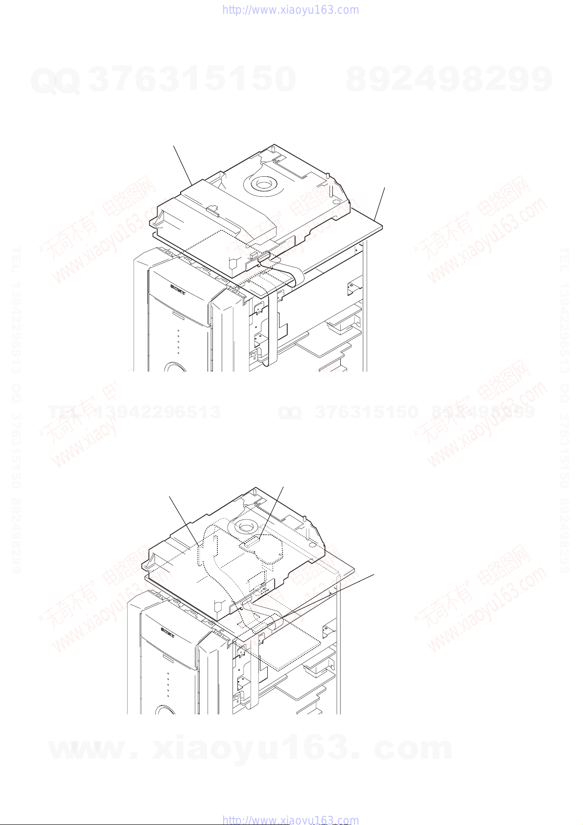
DVD MECHANISM DECK SERVICE POSITION
• In checking the DVD mechanism deck section (CDM53N-DVBU14), prepare e xtension jig (Part No. J-2501-103-A: 1.00 mm Pitch, 29
Q
Q
cores, Length 300 mm).
3
7
6
3
DVD mechanism deck
(CDM53N-DVBV14)
1
5
1
5
0
9
8
Any board to put.
2
4
9
8
2
9
9
TEL 13942296513 QQ 376315150 892498299
TEL
13942296513
Connect extension jig (J-2501-103 A)
to the MB board (CN501) and
RF board (CN002).
7
3
Q
Q
RF board (CN002)
6
3
1
5
1
5
0
8
9
2
4
9
8
2
9
TEL 13942296513 QQ 376315150 892498299
9
6
w
w
w
.
xia
o
y
u
1
6
3
MB board (CN501
.
c
o
m
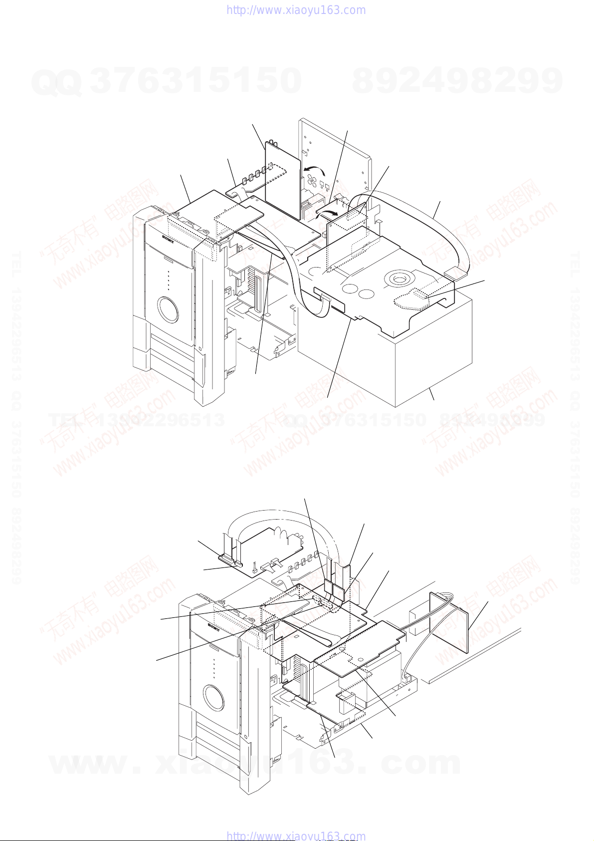
Connect extension jig (J-2501-242-A) to the
DSP board (CN601) and MC board (CN103).
SP RELAY board
Connect extension jig (J-2501-086-A) to the
DSP board (CN602) and MC board (CN104).
FRONT REAR AMP board
SVB TRANS board
TRANS board
chassis
CENTER SW AMP board
Note: When you check the reverse-side side of
CENTER SW AMP board, please move
from a chassis.
MC board
(CN104)
MC board
(CN103)
DSP board
(CN601)
DSP board
(CN602)
Q
HCD-FLX5D/FLX7D
DSP/GC/MB/MC/REGULATOR AND VIDEO BOARDS SERVICE POSITION
• In checking the DSP/GC/MB/MC/REGULA T OR and VIDEO boards, prepare e xtension jig (Part No. J-2501-103-A: 1.00 mm Pitch, 29
Q
cores, Length 300 mm).
3
7
6
3
1
5
1
5
0
8
9
2
4
9
8
2
9
9
DSP board
REGULATOR board
GC board
TEL 13942296513 QQ 376315150 892498299
MC board
DVD mechanism deck
VIDEO board
MB board
(CN501)
Connect extension jig (J-2501-103-A)
to the MB board (CN501) and
RF board (CN002).
TEL 13942296513 QQ 376315150 892498299
RF board
(CN002)
Any box to put.
TEL
13942296513
CENTER SW AMP/FRONT REAR AMP/SP RELAY/SUB TRANS AND TRANS BOARDS SERVICE
POSITION
• In checking the CENTER SW AMP/FRONT REAR AMP/SP RELAY/SUB TRANS and TRANS boards, prepare two extension jigs
(Part No. J-2501-242-A: 1.00 mm Pitch, 11 cores, Length 300 mm and Part No. J-2501-086-A: 1.00 mm Pitch, 19 cores, Length
300 mm).
Q
Q
3
7
6
5
1
3
1
5
0
8
9
2
4
9
8
2
9
9
w
w
w
.
xia
o
y
u
1
6
3
.
c
o
m
7

HCD-FLX5D/FLX7D
IC501 SERVICE POSITION
•When you check IC501, please move a power trans former (T911) from a chassis.
Q
Q
3
7
6
3
1
5
1
5
0
IC501
8
9
2
4
9
8
2
9
9
TEL 13942296513 QQ 376315150 892498299
DECISION TO PASS OR FAIL OF THE OPTICAL
PIC-UP BLOCK
Connection:
TEL
Procedure:
1. Connect an oscilloscope to test point 1 pin and 3 pin
of CN901 on the MB board.
2. Turn the power on.
3. Put the disc (LUV-P01) (Part No.:4-999-032-01) (CD)
in to playback.
4. Conf
5. Put the disc (TDV-520CSO) (Part No.:J-2501-236-A)
6. Perform Comfirmation in the same manner as step 4.
Note: A clear RF signal waveform means that the shape “◊” can be
irm that oscilloscope waveform is clear and check RF
signal level is correct or not.
(DVD) in to playback.
clearly distinguished at the center of the waveform.
13942296513
MB board
CN901 1 pin
CN901 3 pin
oscilloscope
+
–
Checking Location:
– MB BOARD (Component Side) –
71
7
3
Q
Q
CN901
chassis
power transformer
(T911)
1
5
1
3
6
5
0
8
9
2
4
9
8
2
9
TEL 13942296513 QQ 376315150 892498299
9
RF signal waveform
w
w
w
8
.
xia
VOLT/DIV: 200 mV
TIME/DIV: 500 ns
CD: 1.05
DVD: 1.09
±
0.2 Vp-p
±
0.2 Vp-p
o
y
u
1
6
3
.
c
o
m
Q
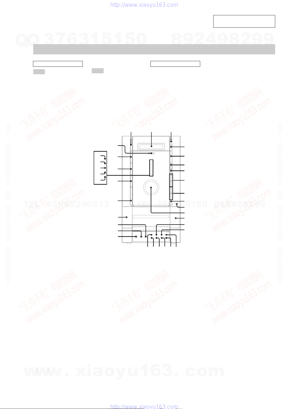
LOCATION OF CONTROLS
7
Q
Main unit
3
6
3
1
SECTION 2
GENERAL
5
1
5
0
8
9
2
HCD-FLX5D/FLX7D
This section is extracted from
instruction manual.
4
9
8
2
9
9
ALPHABETICAL ORDER
A – L
CD SYNC HI-DUB qg
Deck A wg
Deck B qd
DIGITAL wa
DISC SELECT 3
DISC 1 indicator es
DISC 2 indicator ea
DISC 3 indicator e;
TEL 13942296513 QQ 376315150 892498299
DISC 4 indicator wl
DISC 5 indicator wk
Display window 2
DISPLAY qh
DVD ef
ECHO LEVEL wf
EFFECT ql
GROOVE qf
Headphones jack qj
TEL
13942296513
M – Z
MIC jack ws
MIC LEVEL wd
MULTI CHANNEL DECODING
indicator eg
REC PAUSE/START qk
Remote sensor qa
TAPE A/B wj
TUNER/BAND ed
VIDEO/SAT w;
VOLUME qs
1 2 3
?/1
Z
es
ea
e;
wl
wk
eg
ef
ed
wj
wh
Q
wg
wd
ws
BUTTON DESCRIPTIONS
?/1 (power) 1
Z (disc tray) 4
A Z (deck A) wh
Z B (deck B) 0
hH (play) 5
X (pause) 6
x (stop) 7
./> (go back/go forward)
8
−/m, M/+ (rewind, fast
forward) 9
7
3
Q
6
Z
hH
X
x
>
.
M
m
Z
3
TEL 13942296513 QQ 376315150 892498299
4
5
6
7
8
+
9
–
1
q;
5
qa
qs
qd
qf
qg
1
5
0
8
9
2
4
9
8
2
9
9
w
w
w
.
xia
o
y
u
waw;wfqlqkqjqh
1
6
3
.
c
o
m
9
HCD-FLX5D/FLX7D
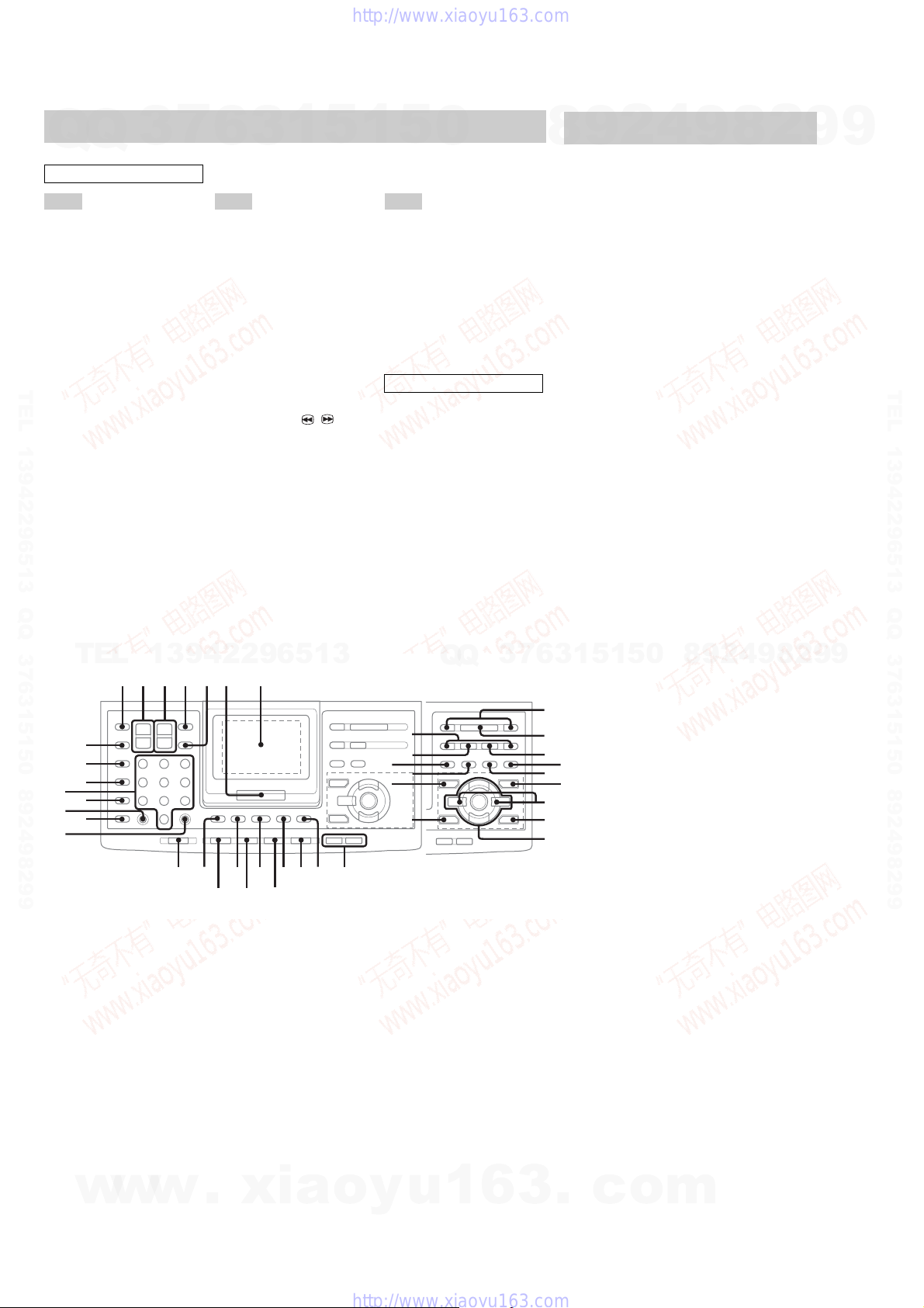
Remote Control
Q
Q
ALPHABETICAL ORDER
A – E
2.1CH/MULTI* e;
ALBUM +/− ed
AMP MENU 9
ANGLE ek
AUDIO el
CLEAR ql
CLOCK/TIMER SELECT* wf
CLOCK/TIMER SET wf
D.SKIP 5
digipad 7
DISPLAY 4
TEL 13942296513 QQ 376315150 892498299
DSP EDIT* ej
DVD qh
DVD DISPLAY* qa
DVD MENU qa
DVD SETUP* 9
DVD TOP MENU qg
EFFECT* es
ENTER 6
3
7
6
F – S T – V
FUNCTION 0
GAME MODE eh
GROOVE* ef
KARAOKE PON* eh
MOVIE MODE es
MUSIC MODE ej
Numeric buttons wd
P FILE* el
PLAY MODE/DIRECTION w;
PRESET +/− wj
PREV/NEXT wj
REPEAT/ FM MODE ws
RETURN O e;
SCAN/SLOW t / T ra
SELECT wk
SHIFT qd
SLEEP wg
SONY TV DIRECT qj
SUBTITLE ea
3
1
5
1
5
0
TAPE A/B qs
TOOL MODE ef
TUNER MEMORY* w;
TUNER/BAND qf
TUNING +/− ra
TV/VIDEO wh
TV ?/1 1
TV CH +/− 3
TV VO L +/− 2
VOLUME +/− 8
BUTTON DESCRIPTIONS
?/1 (power) qk
hH (play) wk
X (pause) r;
x (stop) wl
. (go back) wj
> (go forward) wj
m (rewind) ra
M (fast forward) ra
V/v/B/b/ENTER eg
>10 wa
*To use these functions, press the
button while pressing SHIFT.
Setting the clock
9
8
1 Turn on the system.
2 Press CLOCK/TIMER SET on the
remote.
3 Press . or > repeatedly to set the
hour.
4 Press ENTER on the remote.
5 Press . or > repeatedly to set the
minutes.
6 Press ENTER on the remote.
To adjust the clock
1 Press CLOCK/TIMER SET on the remote.
2 Press . or > repeatedly to select
“CLOCK SET?”, then press ENTER on the
remote.
3 Do the same procedures as step 3 to 6
above.
Note
The clock settings are canceled when you disconnect
the power cord or if a power failure occurs.
2
4
9
8
2
9
9
TEL 13942296513 QQ 376315150 892498299
wd
wa
ql
TEL
wh
wg
wf
ws
w;
13942296513
1 2 3 456 7
9
9
2
8
9
4
2
9
8
0
5
1
5
1
3
6
7
3
Q
Q
wj
ra
r;
el
ek
V
ej
B
v
eh
qd
qg
qjqk
qs
qf
qh
890qa
V
Bb
v
wk
wl
ea
ed
ef
eg
e;
es
10
w
w
w
.
xia
o
y
u
1
6
3
.
c
o
m
Q
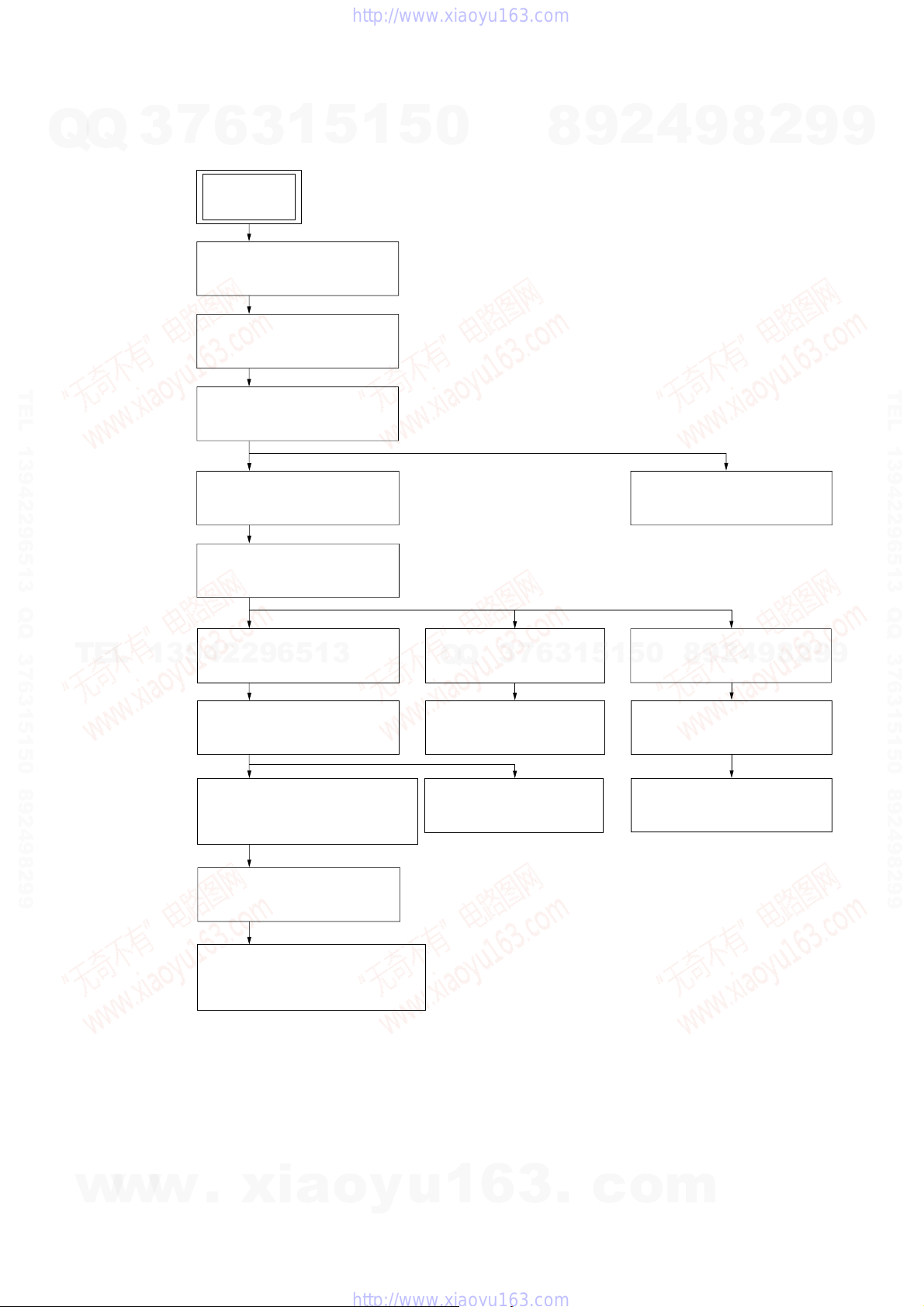
• This set can be disassembled in the order shown below.
7
Q
3
3-1. DISASSEMBLY FLOW
6
SET
3-2. COVER (TOP),
COVER (BACK)
(Page 12)
3-3. CASE
(Page 12)
3
1
5
SECTION 3
DISASSEMBLY
1
5
0
8
9
2
HCD-FLX5D/FLX7D
4
9
8
2
9
9
TEL 13942296513 QQ 376315150 892498299
3-4. FRONT PANEL ASSY
(Page 13)
3-6. GC BOARD
(Page 14)
3-7. DVD MECHANISM BLOCK
(Page 15)
TEL
13942296513
3-8. DSP BOARD
(Page 15)
3-9. DVD MECHANISM DECK
(CDM53N-DVBU14)
(Page 16)
3-10. FITTING BASE (GUIDE)ASSY,
BRACKET (CHASSIS),
MAGNET ASSY
(Page 16)
3-14. VIDEO BOARD
Q
Q
(Page 18)
3-15. SUB TRANS BOARD
(Page 19)
3-11. BASE UNIT
(DVBU14)
(Page 17)
3
7
6
3
1
5
3-5. MECHANICAL
(CASSETTE) DECK
(Page 14)
3-16. BACK PANEL SECTION
0
5
1
(Page 19)
3-17. TRANS BOARD
(Page 20)
3-18. SP RELAY BOARD
(Page 20)
8
9
2
4
9
8
2
9
TEL 13942296513 QQ 376315150 892498299
9
w
w
w
3-12. TRAY (SUB)
(Page 17)
3-13. CHASSIS (MOLD B) SECTION,
STOCKER SECTION,
SLIDER (SELECTION)
(Page 18)
.
xia
o
y
u
1
6
3
.
c
o
m
11
)
HCD-FLX5D/FLX7D
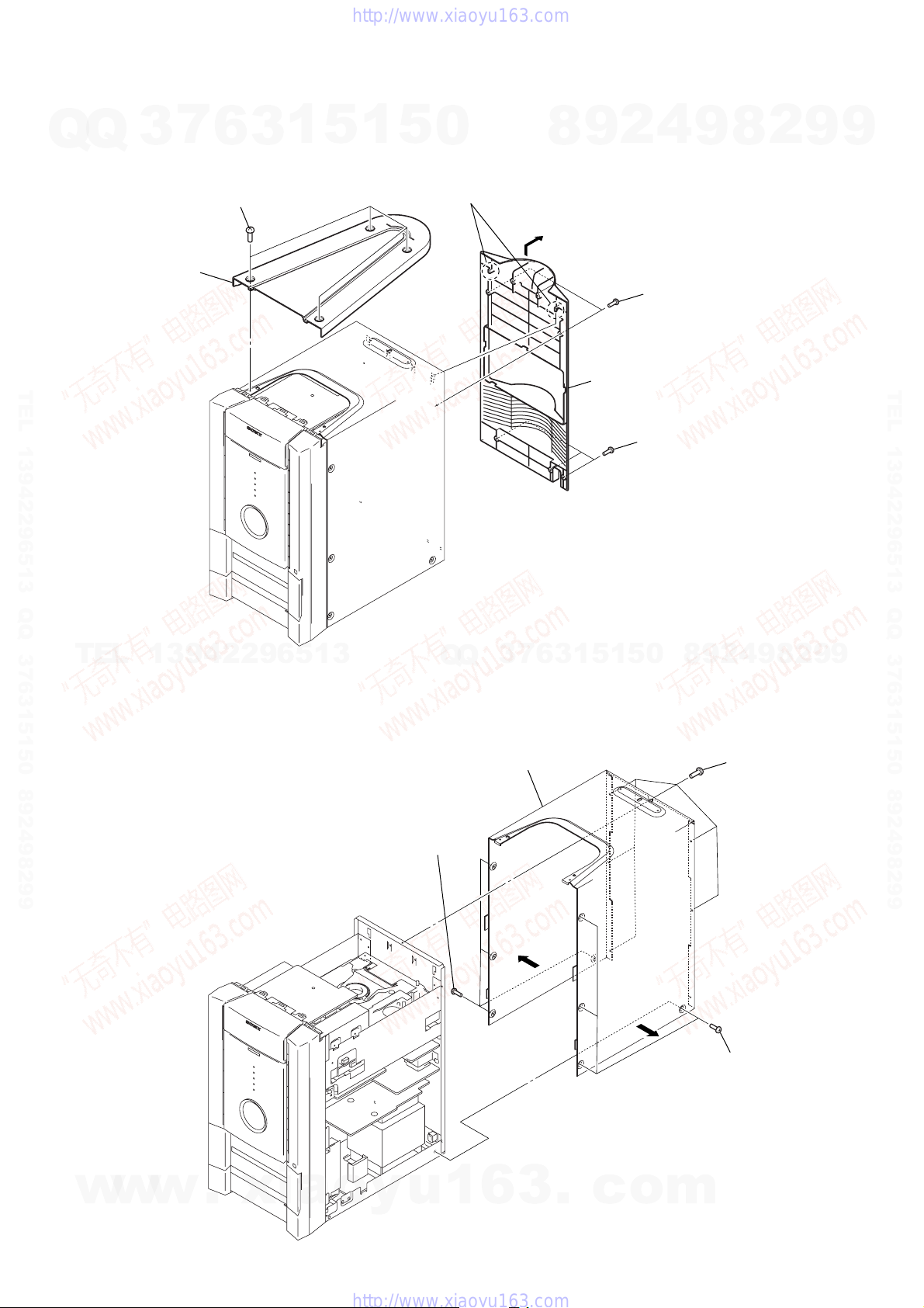
Note: Follow the disassembly procedure in the numerical order given.
7
Q
Q
3-2. COVER (TOP), COVER (BACK)
TEL 13942296513 QQ 376315150 892498299
3
2
cover (top)
6
1
four screws
(case 3 TP2)
3
1
5
1
5
0
4
two claws
8
9
5
4
2
3
two screws
(BVTP3 × 8)
cover (back)
3
three screws
(BVTP3 × 8)
9
8
2
9
9
TEL 13942296513 QQ 376315150 892498299
TEL
3-3. CASE
13942296513
2
four screws
(case 3 TP2)
Q
Q
3
4
7
case
3
6
3
1
5
1
5
0
3
8
9
4
2
1
six screws
(BVTP3
2
four screws
(case 3 TP2)
9
8
2
×
9
9
8
12
w
w
w
.
xia
o
y
u
1
6
3
.
c
o
m
r
Q
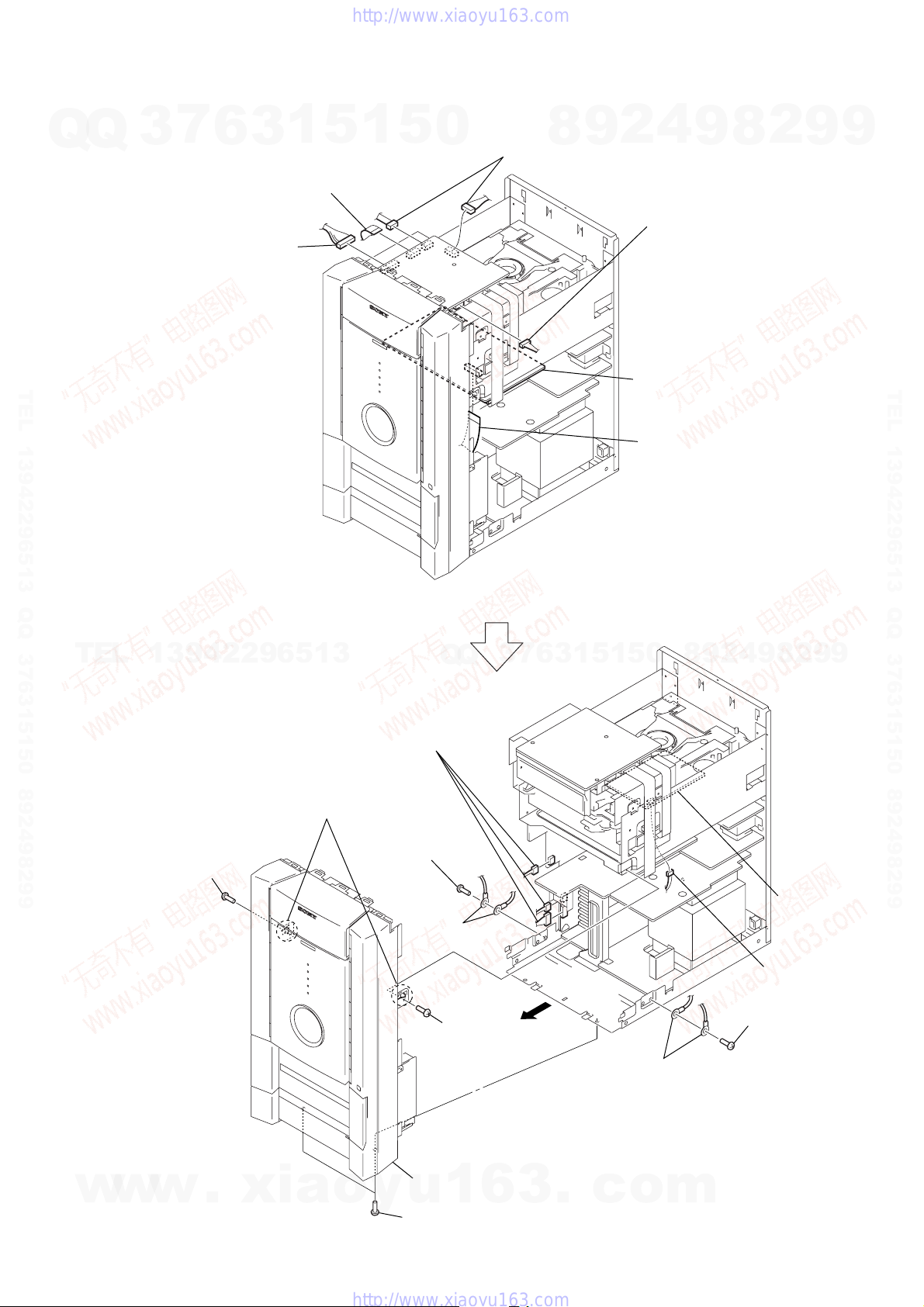
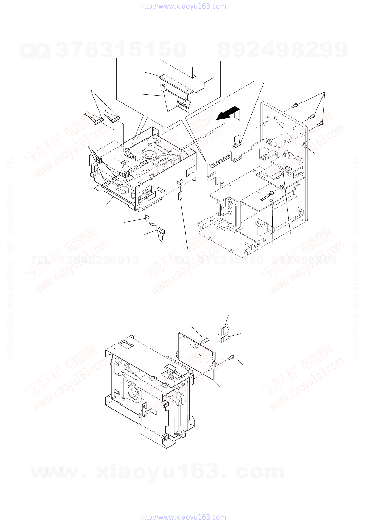
3-4. FRONT PANEL ASSY
7
Q
3
6
3
3
2
connector
(CN201)
1
5
1
wire (flat type) (17 core)
(CN206)
5
0
8
3
two connectors
(CN203, CN208)
9
2
4
3
connector
(CN207)
HCD-FLX5D/FLX7D
9
8
2
9
9
TEL 13942296513 QQ 376315150 892498299
TEL
13942296513
4
two claws
Q
Q
6
three connectors
(CN601, CN602,
CN808)
3
7
6
3
1
5
1
5
MC board
1
wire (flat type) (17 core)
(CN109)
2
9
8
0
4
9
8
2
9
TEL 13942296513 QQ 376315150 892498299
9
w
w
3
screw
(BVTP3
w
×
8)
.
xia
o
1
y
screw
(BVTP3
2
7
front panel assy
u
3
two screws
(BVTP3
×
8)
two ground
terminals
3
screw
(BVTP3
1
6
×
8)
×
8)
3
5
.
c
2
two ground
terminals
o
m
1
6
screw
(BVTP3
DSP board
connecto
(NO803)
×
8)
13
HCD-FLX5D/FLX7D
)
)
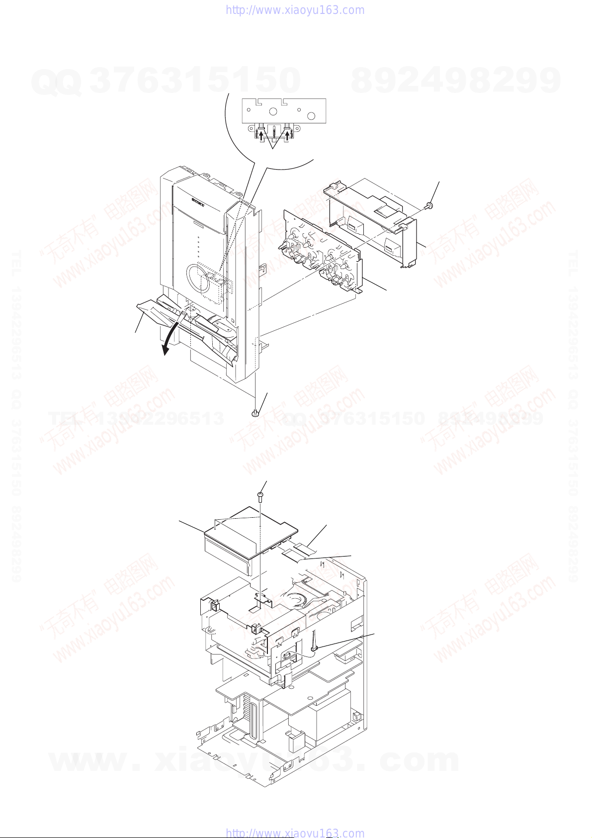
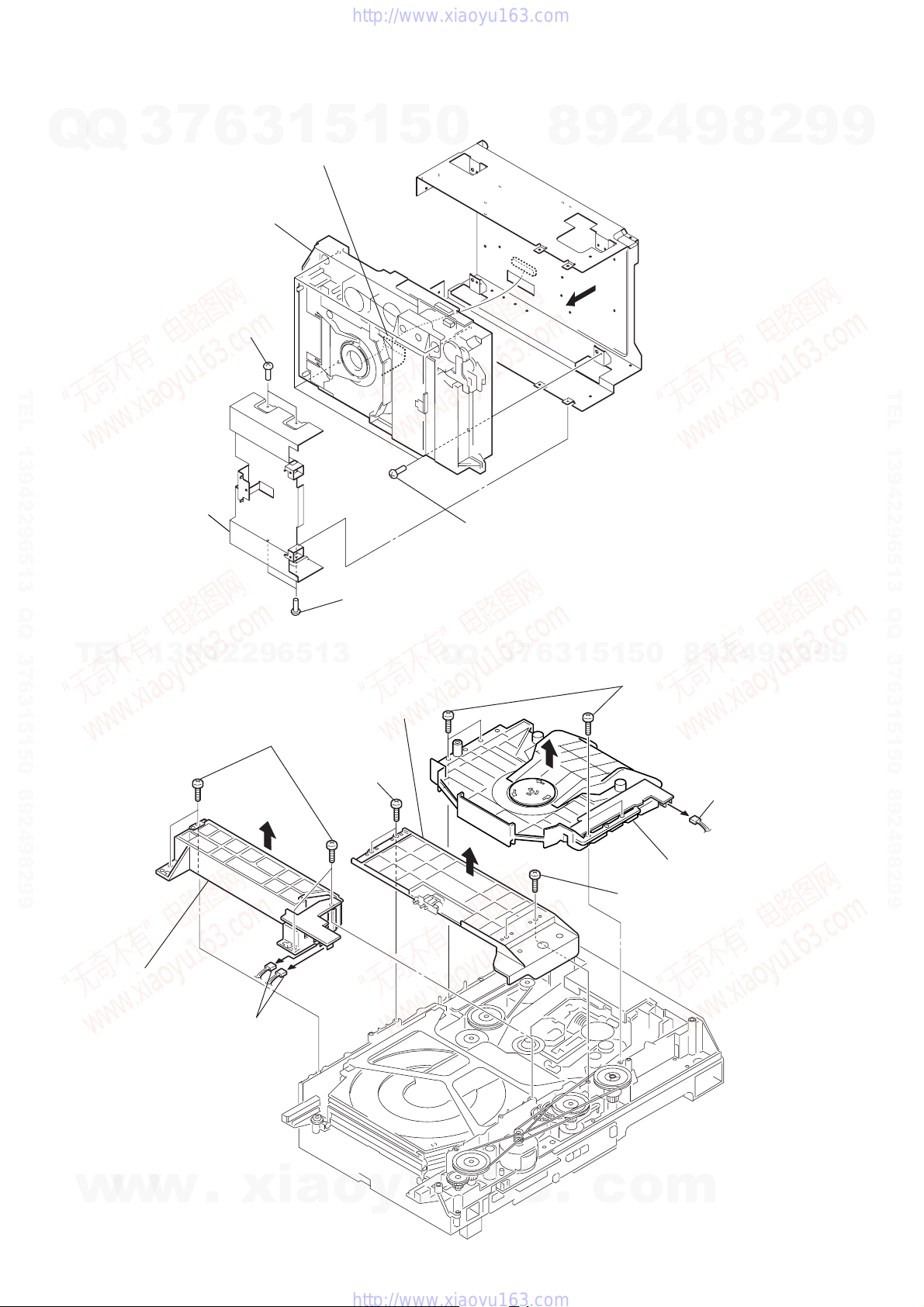
3-5. MECHANICAL (CASSETTE) DECK
Q
Q
3
7
6
3
1
5
1
5
0
4
Push two plunger solenoids
8
9
2
4
9
1
two screws
(BVTP2.6
8
2
×
8
9
9
TEL 13942296513 QQ 376315150 892498299
1
Open the lid (TC)
1
two screws
TEL
3-6. GC BOARD
13942296513
5
GC board
4
three screws
(BVTP3
(BVTP2.6
Q
Q
×
8)
×
3)
7
3
1
wire (flat type) (17 core)
(CN204)
6
3
1
2
cover (TC)
6
mechanical (cassette) deck
8
0
5
1
5
9
2
4
9
8
2
9
TEL 13942296513 QQ 376315150 892498299
9
14
w
w
w
.
xia
o
y
u
1
6
3
2
wire (flat type) (19 core
(CN202)
3
connector
(CN701)
.
c
o
m
)
)
Q
3-7. DVD MECHANISM BLOCK
Q
7
3
2
two connectors
(CN702, CN703)
4
two connectors
(CN805, CN806)
6
3
1
5
MC board
SP RELAY
board
1
5
5
two claws
0
8
9
2
HCD-FLX5D/FLX7D
4
2
connector
(CN807)
9
8
2
3
9
9
six screws
(BVTP3 × 8
TEL 13942296513 QQ 376315150 892498299
7
DVD mechanism block
1
wire (flat type) (11 core)
(CN105)
TEL
13942296513
3-8. DSP BOARD
Note: Please turn a DSP/MB/MC boards side down and do not do decomposition work.
2
connector
(CN905)
1
1
wire (flat type) (9 core)
(CN603) (FLX7D)
wire (flat type) (9 core)
(CN401) (FLX7D)
Q
Q
3
7
6
5
1
5
1
3
2
wire (flat type) (19 core)
(CN602)
3
wire (flat type) (11 core
(CN601)
0
2
connector
(CN903)
9
8
1
wire (flat type)
(17 core) (CN204)
8
9
4
2
6
2
claw
9
TEL 13942296513 QQ 376315150 892498299
9
w
w
w
.
xia
o
y
u
1
6
3
5
DSP board
.
4
c
two screws
(BVTP3
o
×
m
8)
15
r
HCD-FLX5D/FLX7D
3-9. DVD MECHANISM DECK (CDM53N-DVBU14)
Q
Q
7
3
5
DVD mechanism deck (CDM53N-DVBU14)
6
1
two screws
(BVTP3
1
3
3
wire (flat type) (29core)
(CN501)
×
8)
5
1
5
0
4
2
9
8
Note: Please turn a DSP/MB/MC boards side
down and do not do decomposition work.
9
8
2
9
9
TEL 13942296513 QQ 376315150 892498299
2
bracket (FL)
1
two screws
×
(BVTP3
TEL
3-10. FITTING BASE (GUIDE) ASSY, BRACKET (CHASSIS), MAGNET ASSY
13942296513
2
four screws
(BTTP M2.6)
4
two screws
(BTTP M2.6)
6
bracket
(chassis)
8)
Q
4
Q
four screws
(BVTP3
3
7
×
6
8)
3
1
5
1
5
8
9
8
0
four screws
(BTTP M2.6)
2
7
connecto
(CN710)
4
9
8
2
9
TEL 13942296513 QQ 376315150 892498299
9
16
3
w
w
fitting base
(guide) assy
w
1
two connectors
(CN709, CN715)
.
xia
o
y
u
1
6
3
.
c
5
two screws
(BTTP M2.6)
o
9
magnet assy
m
)
Q
3-11. BASE UNIT (DVBU14)
7
Q
3
6
2
four screws
(BTTP M2.6)
3
1
5
1
5
0
4
magnet assy
1
connector
(CN710)
8
9
2
HCD-FLX5D/FLX7D
4
9
8
2
9
9
TEL 13942296513 QQ 376315150 892498299
3
two hooks
TEL
13942296513
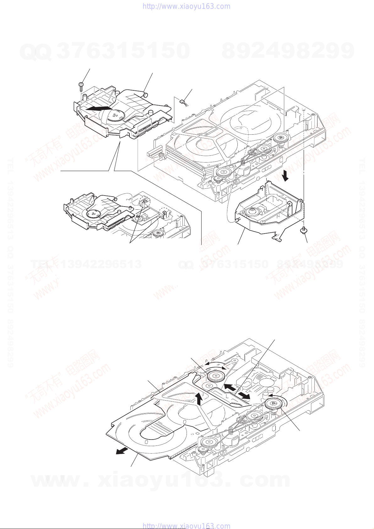
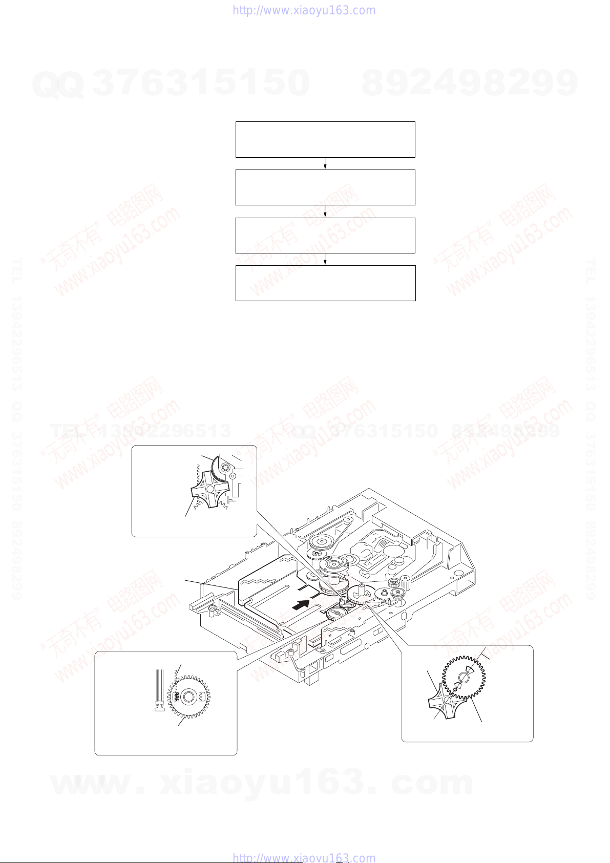
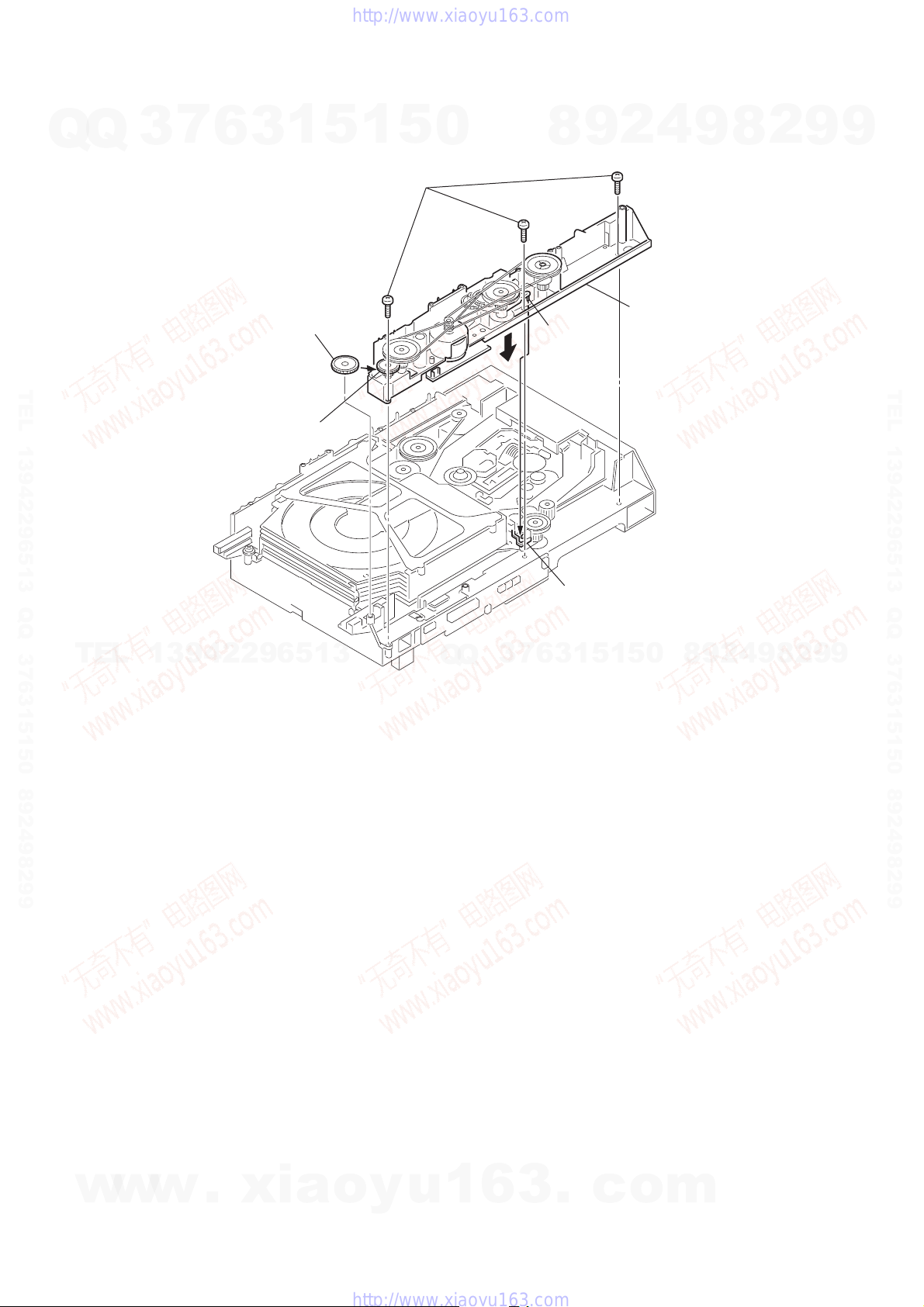
3-12. TRAY (SUB)
1
Rotating the pulley (LD), shift the slider (selection) in the arrow A direction.
2
Rotating the pulley (mode) in the arrow direction, adjust the tray (sub) to be removed.
3
Rotating the pulley (LD), shift the slider (selection) in the arrow B direction.
4
Rotating the pulley (mode) in the arrow direction, remove the tray (sub) to be removed.
Q
Q
3
7
6
base unit (DVBU14)
3
6
1
5
1
0
5
slider (selection)
8
9
5
2
two screws
(PTPWH M2.6
2
8
9
4
9
TEL 13942296513 QQ 376315150 892498299
9
w
w
w
.
xia
stocker section
tray (sub)
o
pully (LD)
y
u
1
6
3
.
A
c
B
o
pully (mode)
m
17
)
HCD-FLX5D/FLX7D
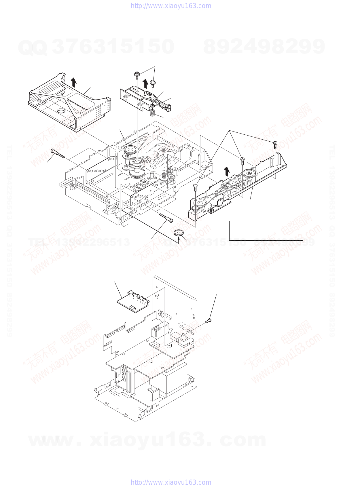
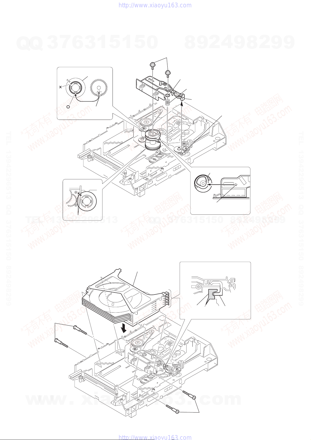
3-13. CHASSIS (MOLD B) SECTION, STOCKER SECTION, SLIDER (SELECTION)
Q
Q
3
7
6
6
section
3
stocker
1
5
pully (LD)
1
7
5
0
two screws
(PTPWH M2.6)
8
slider (selection)
0
9
washer
compression
spring
8
1
three screws
(BVTP M2.6)
9
2
4
9
8
2
9
9
TEL 13942296513 QQ 376315150 892498299
5
two step
screws
4
TEL
3-14. VIDEO BOARD
13942296513
2
VIDEO board
two step screws
Q
Q
7
3
3
gear (eject)
3
6
1
four screws
(BVTP3 × 8
1
2
chassis (mold B) section
Note: Rotating the pully (LD),
shift the slider (selection)
to the left.
9
8
0
5
1
5
2
4
9
8
2
9
TEL 13942296513 QQ 376315150 892498299
9
18
w
w
w
.
xia
o
y
u
1
6
3
.
c
o
m
s
l
)
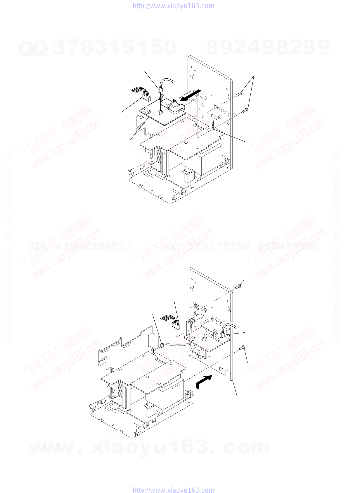
3-15. SUB TRANS BOARD
7
Q
Q
TEL 13942296513 QQ 376315150 892498299
3
6
5
1
3
1
connector
(CN902)
SUB TRANS board
5
1
1
connector
(CN901)
5
0
3
8
9
2
HCD-FLX5D/FLX7D
4
9
2
three screw
(BVTP3 × 8)
4
ground termina
8
2
9
9
TEL 13942296513 QQ 376315150 892498299
TEL
13942296513
3-16. BACK PANEL SECTION
4
connector
(CN809)
1
connector
(CN902)
Q
Q
3
7
6
3
3
1
0
5
1
5
2
two screws
(BVTP3 × 8)
5
back panel section
9
8
1
connector
(CN901)
2
screw (BVTP3 × 8
2
4
9
8
2
9
9
w
w
w
.
xia
o
y
u
1
6
3
.
c
o
m
19
HCD-FLX5D/FLX7D
d
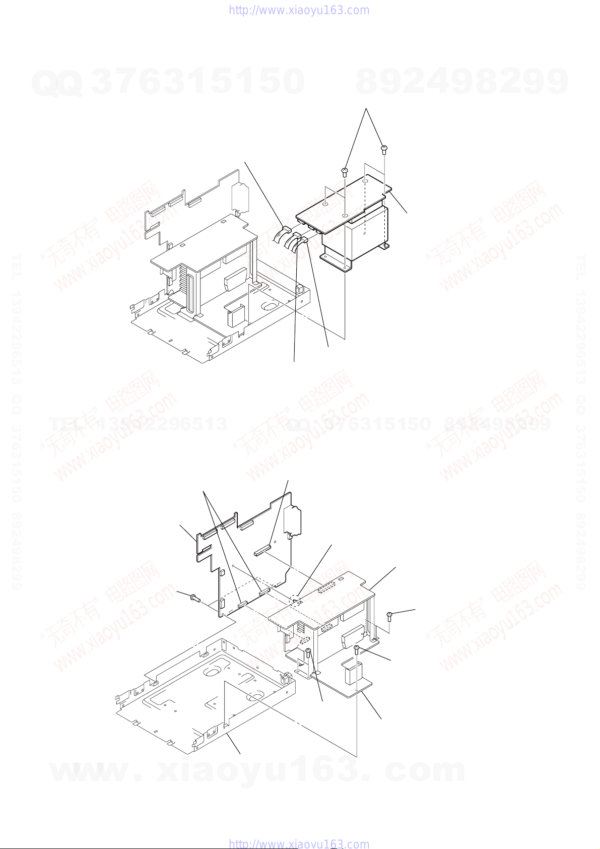
3-17. TRANS BOARD
7
Q
Q
3
6
3
1
5
1
connector (CN914)
1
5
0
8
2
four screws
9
4
2
3
TRANS board
9
8
2
9
9
TEL 13942296513 QQ 376315150 892498299
1
connector (CN915)
1
connector (CN916)
TEL
3-18. SP RELAY BOARD
13942296513
3
two connectors
(CN803, CN804)
6
SP RELAY board
5
connector
(CN801)
Q
Q
7
3
4
PC board holder
6
3
1
5
1
5
0
8
9
2
4
9
8
2
9
TEL 13942296513 QQ 376315150 892498299
9
20
w
w
1
w
two screws
(BVTP3 × 8)
.
xia
1
two screws
(BVTP3 × 8)
2
chassis
o
y
u
1
6
3
FRONT REAR AMP boar
1
1
screw (BVTP3 × 8)
CENTER SW AMP board
.
c
o
two screws
(BVTP3 × 8)
m
SECTION 4
ASSEMBLY
• This set can be assembled in the order shown below.
7
Q
Q
TEL 13942296513 QQ 376315150 892498299
3
4-1. ASSEMBLY FLOW
6
3
1
5
1
5
0
4-2. GEARS INSTALLATION
(Page 21)
4-3. SLIDER (SELECTION) INSTALLATION
(Page 22)
4-4. STOCKER SECTION INSTALLATION
(Page 22)
4-5. CHASSIS (MOLD B) SECTION
INSTALLATION (Page 23)
8
9
2
HCD-FLX5D/FLX7D
4
9
8
2
9
9
TEL 13942296513 QQ 376315150 892498299
Note: Follow the assembly procedure in the numerical order given.
4-2. GEARS INSTALLATION
TEL
13942296513
1
2
3
gear (gear B)
portion A
Adjust the gear (gear B) with the
portion A as shown.
Slide the slider (u/d)
fully in the arrow
direction.
gear (U/D slider)
slider (U/D) gear
Q
Q
3
7
6
3
1
5
5
1
4
gear (gear A)
gear
(gear B)
0
8
9
2
9
4
linearly
8
2
9
9
w
w
Adjust the gear so that it meshes with
the bottom tooth of slider (U/D) gear,
as shown.
w
.
xia
o
y
u
1
6
3
.
Adjust so as to be aligned with
gear B linearly, as shown.
c
o
m
21
HCD-FLX5D/FLX7D
4-3. SLIDER (SELECTION) INSTALLATION
Q
Q
3
7
6
2
gear (chuking)
3
1
5
1
5
0
6
two screws
(PTPWH M2.6)
8
9
2
4
9
8
2
9
9
rotary encoder
Align with the slot of
rotary encoder.
TEL 13942296513 QQ 376315150 892498299
1
rotary encoder
TEL
13942296513
align marking
Q
Q
3
7
5
washer
4
compression spring
7
Insert the slider (selection)
into the portion A.
3
convex portion of
slider (selection)
gear (chuking)
Insert a convex portion into
a groove of gear (chuking).
5
1
5
1
3
6
portion A
0
8
9
2
4
9
8
2
9
TEL 13942296513 QQ 376315150 892498299
9
4-4. STOCKER SECTION INSTALLATION
3
two step screws
1
stocker section
2
portion A of tray (sub)
Hook the portion A of tray (sub)
to the slider (selection).
portion A
of tray (sub)
sticking of
slider (selection)
22
w
w
w
.
xia
o
y
u
1
6
3
.
c
o
3
two step screws
m
Q
4-5. CHASSIS (MOLD B) SECTION INSTALLATION
Q
3
7
6
2
1
3
Insert the gear (eject)
under the gear (LD
deceleration).
5
3
three screws
(BVTP M2.6)
1
5
0
8
portion A
9
HCD-FLX5D/FLX7D
4
2
1
9
Insert the portion A of
chassis (mold B) section
into the portion B of
slider (selection).
8
2
9
9
TEL 13942296513 QQ 376315150 892498299
gear (LD deceleration)
TEL
13942296513
Q
Q
3
7
portion B of
slider (selection)
1
3
6
5
1
5
0
8
9
2
4
9
8
2
9
TEL 13942296513 QQ 376315150 892498299
9
w
w
w
.
xia
o
y
u
1
6
3
.
c
o
m
23
HCD-FLX5D/FLX7D
SECTION 5
TEST MODE
[COLD RESET]
• The cold reset clears all data including preset data stored in the
Q
Q
RAM to initial conditions. Execute this mode when returning
the set to the customer.
Procedure:
1. Press three buttons [ ], [DISPLAY], and [GROOVE] simulta-
neously.
2. The fluorescent indicator tube becomes blank instantaneously,
and the set is reset.
[TUNER STEP CHANGE]
(Except FLX5D: Saudi Arabia/FLX7D: Saudi Arabia models)
• A step of AM channels can be changed o ver between 9 kHz and
10 kHz.
Procedure:
1. Press the [I/ ] button to turn the power on.
TEL 13942296513 QQ 376315150 892498299
2. Select the function “TUNER”, and press [TUNER/BAND] button to select the BAND “AM”.
3. Press the [I/ ] button to turn the set OFF.
4. Press M + and [I/ ] buttons simultaneously , and the display
of fluorescent indicator tube changes to “ AM 9 K Step” or “AM
10 K Step”, and thus the channel step is changed over.
[FUNCTION CHANGE MODE]
• Select either VIDEO or MD of the external function input.
Procedure:
1. Press the [I/ ] button to turn the power on.
2. Hold down [VIDEO $SAT%] button then press [I/ ] button, and
release [I/ ] button first in order not in switch off the set immediately.
The another function of the previous function is selected, the
input level is also changed and displayed “SAT” or “VIDEO”.
1
TEL
[GC TEST MODE]
• This mode is used to check the software version, FL tube, LED,
keyboard and VACS.
Procedure:
1. Press three buttons [ ], [DISPLAY], and [EFFECT] simultaneously.
2. LEDs and fluorescent indicator tube are all turned on.
3. When you want to enter the software version display mode,
press [GROOVE] . The model number and destination are dis-
played.
4. Each time [GROOVE] is pressed, the display changes stating
from MC version, GC version, DP version, DVD version,
CDDM, CDMA, CDMB, BDA, BDB, ST version, TA version,
TM version, TC version, in this order.
5. When [CD SYNC HI-DUB] is pressed while the version num-
bers are being displayed except model number and destination, year, month and day of the software creation appear. When [CD SYNC HI-DUB] is pressed again, the display
returns to the software version display. When [GROOVE]
is pressed while year, month and day of the software creation
are being displayed, the year, month and day of creation of the
software versions are displayed in the same order of version
display.
6. Press [EFFECT] button, and the key check mode is activated.
7. In the key check mode, the fluorescent indicator tube displays
“KXX V0 C T”. Each time a button is pressed, “K” value
decreases.
However, once a button is pressed, it is no longer taken into
account.
“V” value increases like 1, 2, 3...if rotating [VOLUME] knob
in the clockwise, or it decreases like 0, 9, 8...if rotating in the
counterclockwise.
w
w
Each time the “CD DOOR LOCK DETECT” or “CD DOOR
OPEN/CLOSE DETECT” switch is turned on, “C” value in-
3
1
1
1
7
x
1
6
3
1
13942296513
x
w
.
xia
5
1
o
1
y
5
u
creases.
Each time the “CASSETTE LID OPEN/CLOSE DETECT”
0
switch is pressed, “T” value increases.
8. Also when [GROOVE] is pressed after lighting of all LEDs
and fluorecsent indicator tube, value of VACS appears.
9. To exit from this mode, press three buttons in the same manner as step 1, or disconnect the power cord.
[MC TEST MODE]
• This mode is used to check operations of the respective sections
of Amplifier, Tuner , and Tape.
1. Entering the MC Test Mode
Procedure:
1. Press the [I/ ] button to turn the power on.
2. Press the three buttons of [ ], [DISPLAY] and [CD SYNC HI-
DUB] simultaneously.
3. The segments blinks on the fluorescent indicator tube as bellow.
DIGITAL
2. Releasing the MC Test Mode
Procedure:
1. To release this mode, press the [I/ ] button.
2. The cold reset is enforced at the same time.
7
3
Q
Q
3. Chec k of Amplifier
Initial settings:
Input , DIGITAL
EQ , FLAT
Mode , MUSIC
VACS , OFF
Output channel setting:
Each time the [EFFECT] button is pressed, output channels switch
as following order.
Order Channels Bass Manage VACS*
6
3
L t L
R t R
L t L
R t R
L t SL
R t SR
L t SL
R t SR
L t L, C, SL
R t R, SR, SW
L t L, C, SL
R t R, SR, SW
L t C
R t SW
L t C
R t SW
1
2
3
4
5
6
7
8
1
*1) “EFFECT” indication
8
1
6
3
.
9
1
1
5
c
2
x
5
o
4
EFFECT
1
8
0
Through ON
Through OFF
Through ON
Through OFF
Through ON
Through OFF
8
9
Blink
2
9
on ON
on OFF
m
4
2
9
8
9
2
1
9
9
TEL 13942296513 QQ 376315150 892498299
9
24
HCD-FLX5D/FLX7D
Volume check:
Q
TEL 13942296513 QQ 376315150 892498299
1. When the
Q
the sound volume increases to its maximum and a message
“VOLUME MAX” appears for two seconds, then the display
returns to the original display.
2. When the [VOLUME] knob is turned counterclockwise even
slightly, the sound volume decreases to its minimum and a
message “VOLUME MIN” appears for two seconds, then the
display returns to the original display.
Tuner Function
1. In the test mode, the default-preset channel is called even when
the TUNER is selected and an attempt is made to call the preset channel that has been stored in memory. (It means that the
memory is cleared)
2. The minimum, center and maximum frequency of each band
is set then.
4. Tape Recording Test
Procedure:
1. Enter the MC Test Mode.
2. Load tapes in both tape decks A and B.
3. Press the REC button to start recording.
4. Pressing the
the tape to the recording start position and stops it at this position.
5. Pressing the “High Speed Dubbing” key while playing back
the tape of deck B switches the playback speed between “Normal Speed” and “High Speed”.
Note:
When the playback direction of the tape is set to other than “ONY WAY”,
the restriction on the number of times playback which can be repeated
will be cleared.
TEL
5. AMS T est Mode
Procedure:
1. Enter the MC Test Mode and press the [TAPE A/B] button to
set the TAPE function.
2. Insert a test tape AMS-110A or AMS-120 to deck A.
3. Press the > button to enter the AMS test mode.
4. After a tape is rewound first, the FF AMS is checked, and the
mechanism is shut off after detecting the AMS signal the AMS
signal twice.
5. Then the REW AMS is checked and the mechanism is shut off
after detecting the AMS signal twice.
6. When the check is complete, a message of either OK or NG
appears.
[VOLUME] knob is turned clockwise even slightly,
3
7
–
6
m or M
3
1
+
buttons during recording returns
13942296513
5
1
5
0
Q
Q
[DVD SHIP MODE (NO MEMORY CLEAR) ]
• This mode moves the optical pick-up to the position durable to
vibration. Use this mode when returning the set to the customer
after repair.
Procedure:
1. Press the [I/ ] button to turn the power on.
2. Press the [DVD] and [I/ ] buttons simultaneously.
3. After the “STANDBY” display blinks, a message “LOCK” is
displayed on the fluorescent indicator tube, and the CD ship
mode is set.
[VACS ON/OFF MODE]
• This mode is used to switch on or off the VACS (Variable At-
tenuation Control System).
Procedure:
1. Press two buttons of > and [A ] for more than 1 second
simultaneously.
2. When VACS is switch on, it displays “VACS OFF”.
When VACS is switch off, it displays “VACS O”.
[CD REPEAT 5 LIMIT OFF MODE]
Number of repeat for CD playback is 5 times when the repeat
mode is “REPEA T”. This mode enables CD to repeat playback for
limitless times.
Procedure:
1. Press the [I/ ] button to turn the power on, and press the [DVD]
button to select the function “DVD”.
2. Press two buttons of > and [CD SYNC HI-DUB] for more
than 1 second simultaneously to enter the CD repeat 5 limit off
mode.
3. To release this mode, operate the cold reset. (Refer to the “MC
COLD RESET”)
7
3
[DISC TRA Y LOCK]
Procedure:
1. Press the [I/ ] button to turn the power on.
2. Press the [DVD] button to select the function “DVD”.
3. Press two buttons of Z (DVD) and x simultaneously for five
seconds.
4. The message “LOCKED” is displayed and the tray is locked.
(Even if exiting from this mode, the tray is still locked)
5. To exit from this mode, press two buttons of Z (DVD)
and x simultaneously for five seconds again.
6. The message “UNLOCKED” is displayed and the tray is unlocked.
8
6
3
9
1
1
5
1
1
2
1
5
4
0
2
8
9
1
Z
8
9
4
2
9
8
9
2
9
9
TEL 13942296513 QQ 376315150 892498299
9
6. ALC MODE
Procedure:
1. Enter the MC Test Mode and press the [REC PAUSE/START]
button 2 times to recording start.
2. While pressing the . button, ALC is on.
(normaly, ALC is off in recording state.)
[DVD SHIP MODE (MEMORY CLEAR) ]
• This mode moves the optical pick-up to the position durable to
vibration. Use this mode when returning the set to the customer
after repair.
Procedure:
1. Press the [I/ ] button to turn the power on.
2. Press three buttons x , [CD SYNC HI-DUB] and [DVD]
simultaneously.
3. After the “STANDBY” display blinks, a message “LOCK” is
w
displayed on the fluorescent indicator tube, and the CD ship
w
w
mode is set.
1
.
xia
o
y
u
1
6
3
.
c
o
m
25
HCD-FLX5D/FLX7D
[DVD TEST MODE GENERAL DESCRIPTION]
The T est Mode allo ws you to make dia gnosis and adjustment eas-
Q
Q
ily using the remote commander and monitor TV. The instructions,
diagnostic results, etc. are given on the on-screen display (OSD).
[TEST DISC LIST]
Use the following test disc on test mode.
TDV-520CSO (DVD-SL): PART No. J-2501-236-A
LUV-P01 (CD): PART No. 4-999-032-01
TDV-540C (DVD-DL): PART No. J-2501-235-A
Note: Do not use existing test disc for DVD.
[STARTING DVD TEST MODE]
1. Press the [I/ ] button to turn the power on.
2. Select the function “DVD”.
3. Press the [I/ ] button to turn the power off.
TEL 13942296513 QQ 376315150 892498299
4. While pressing the x button, press the Z (DVD) button and
turn the [VOLUME] knob in the clock wise.
5. It displays “SERVICE IN” on the fluorescent indicator tube,
and displays the Test Mode Menu on the monitor screen as
follows. (At the bottom of the menu screen, the model name
and revision number are displayed)
0. Syscon Diagnosis
1. Drive Auto Adjustment
2. Drive Manual Operation
3. Mecha Aging
4. Emergency History
5. Mecha Error History
6. Version Information
7. Video Level Adjustment
TEL
Model :DHC-FLxx xx
Revision :x.xx
6. To execute each function, select the desired menu and press its
number on the remote commander (RM-SFL7).
7. To release from test mode, press the I/1 button and turn the
power off.
[OPERATING DVD TEST MODE]
0. SYSCON DIAGNOSIS
The same contents as board detail check by serial interface can be
checked from the remote commander operation.
On the Test Mode Menu screen, pr ess [10/0] key on the remote
commander, and the following Check Menu will be displayed.
### Syscon Diagnosis ###
0. Quit
1. All
2. Version
3. EEPROM
4. GPIO
5. SD Bus
6. Video
7. Audio
7
3
1
1
Test Mode Menu
6
3
1
13942296513
Exit: POWER Key
Check Menu
5
1
5
0-1. All (All items continuous check)
This menu checks all diagnostic items continuously. Normally, all
0
items are checked successively one after another automatically unless an error is found, but at a certain item that requires judgment
through a visual check to the result, the following screen is displayed for the key entry.
•
Example display
### Syscon Diagnosis ###
Check Sum = 2320
Press NEXT Key to Continue
Press PREV Key to Repeat
For the ROM Check, the check sum calculated by the Syscon is
output, and therefore you must compare it with the specified value
for confirmation.
Following the message, press the [NEXT ] button to go to the
next item, or press the [PREV ] button to repeat the same
operation again.
To quit the diagnosis and return to Check Menu screen, press the
[RETURN] key on the remote commander to display Check Menu.
7
3
Q
Q
• Error occurred
If an error occurred, the diagnosis is suspended and error is displayed.
Press the [RETURN] key on the remote commander to quit the
diagnosis, or press the [PREV ] button to repeat the same
check where an error occurred, or press the [NEXT ] button to
continue the check from the item next to faulty item.
General Description of Checking Method
Selecting 2 and subsequent items calls the submenu screen of each
item. And selecting 2 and subsequent items executes respective
menus and outputs the results.
For the contents of each submenu, see “Check Items List” as below.
Check Items List:
0-2. Version
0-2-1. All
0-2-2. Revision
0-2-3. ROM Check Sum
0-2-4. Model Type
0-2-5. Region
0-3. EEPROM Check
0-3-1. Sampling Check
0-4. GP I/O Check
0-5. SD Bus Check
0-6. Video Check
0-7. Audio Check
2
9
8
Diag All Check
No.2 Version
2-3. ROM Check Sum
.
0
5
1
5
1
3
6
.
4
>
8
9
9
8
2
4
>
2
9
8
9
2
9
9
TEL 13942296513 QQ 376315150 892498299
9
w
w
0-0. Quit
w
Quit the Syscon Diagnosis and return to the Test Mode Menu.
26
.
xia
o
y
u
1
6
3
.
c
o
m
HCD-FLX5D/FLX7D
0-2. Version
Q
TEL 13942296513 QQ 376315150 892498299
0-2-2. Revision
Q
0-2-3. ROM Check Sum
0-2-4. Model Type
0-2-5. Region
0-3. EEPROM Check
0-3-1. Sampling Check
0-3-2. Detail Check
7
3
The revision number of ROM (IC204) that the program f or
the DVD system processor (IC206) is stored.
(4 digits hexadecimal number)
The revision number of ROM (IC204) that the program f or
the DVD system processor (IC206) is stored.
Model name is displayed. (DHC-FL5D or DHC-FL7D)
Model destination code is displayed. (2 digits number)
EEPROM check at every 64 words.
It compares read data with write data of each address. When
there are discrepancies between two data, it displays error.
EEPROM check at every 1 word.
It compares read data with write data of each address. When
there are discrepancies between two data, it displays error.
6
3
1
5
1
5
0
1. DRIVE AUTO ADJUSTMENT
On the Test Mode Menu screen, press the [1] key on the remote
commander, and the Adjustment Menu will be displayed.
Normally, [10/0] is selected to adjust DVD (single layer), CD and
DVD (dual layer) in this order. But, individual items can be adjusted for the case where adjustment is suspended due to an error.
In this mode, the adjustment can be made easily through the operation following the message displayed on the screen.
The disc used for adjustment must be the one specified for adjustment.
4
2
9
8
## Drive Auto Adjustment ##
Adjustment Menu
0. ALL
1. DVD-SL
2. CD
3. DVD-DL
9
2
8
Exit: RETURN
9
9
TEL 13942296513 QQ 376315150 892498299
0-4. GP I/O Check
Pull up/down setting check of the DVD system processor (IC206)
pin 150, 151 and 154 (for clock setting port).
0-5. SD Bus Check
SD bus data check between DVD decoder (IC701) and MPEG
TEL
13942296513
DECODER (IC206).
0-6. Video Check
Output the color bars for video level adjustment.
0-7. Audio Check
Output the test signal (1kHz sine wave) for 2 CH test.
Q
Q
1-0. ALL
Press the [10/0] key on the remote commander, and the servo set
data in EEPROM will be initialized. Then, 1. D VD-SL disc, 2. CD
disc and 3. DVD-DL disc are adjusted in this order.
Each time one disc was adjusted, it is ejected. Replace it with the
specified disc following the message. You can finish the adjust-
6
7
3
ment by pressing the [RETURN] button on the remote commander.
Note: During adjustment of each disc, the measurement for disc type judg-
1-1. DVD-SL (single layer)
Press the [1] key on the remote commander and insert a DVD single
layer disc following the message. Then the adjustment will be made
through the steps, then adjusted values will be written to the
EEPROM.
1-2. CD
Press the [2] key on the remote commander and insert a CD disc
following the message. Then the adjustment will be made through
the steps, then adjusted values will be written to the EEPROM.
1-3. DVD-DL (dual layer)
Press the [3] key on the remote commander and insert a D VD dual
layer disc following the message. Then the adjustment will be made
through the steps, then adjusted values will be written to the
EEPROM.
5
1
3
ment is made. As automatic adjustment does not judge the disc
type unlike conventional models, take care not to insert wrong type
discs. Also, do not give a shock during adjustment.
1
5
0
8
9
2
4
9
8
2
9
9
w
w
w
.
xia
o
y
u
1
6
3
.
c
o
m
27
HCD-FLX5D/FLX7D
2. DRIVE MANUAL OPERATION
Note: This mode is used for design, and not used in service fundamen-
Q
Q
tally.
On the Test Mode Menu screen, press the [2] key on the remote
commander, and the Operation Menu will be displayed. For the
manual operation, each servo on/off control and adjustment can
be executed manually.
## Drive Manual Operation ##
1. Disc Type
2. Servo Control
3. Track/Layer Jump
4. Non EEPROM Write Adjust
5. EEPROM Write Adjust
TEL 13942296513 QQ 376315150 892498299
6. Memory Check
7. Disc Check Memory
8. Error Rate Display
9. SACD Water Mark
In using the manual operation menu, take care of the following
points. These commands do not provide protection, thus requiring
correct operation. The sector address or time code field is displayed when a disc is loaded.
Note:
1. Set correctly the disc type to be used on the Disc Type screen.
2. In case of an alarm, exit the manual operation menu immediately to stop the servo operation, and press the I/1 button to
turn the power off.
TEL
Basic operation:
(controllable from front panel or remote commander)
[POWER] :Power OFF (release the Test Mode)
Z : Stop and eject/Loading
[RETURN] : Return to Operation Menu or Test
[PREV ], [NEXT ] :Transition between sub modes of
[1] to [9], [10/0] : Selection of menu items
Cursor o/
O
7
3
6
Operation Menu
1
3
Exit: RETURN
13942296513
Mode Menu
>.
menu
: Increase/Decrease in manually ad-
justed value
5
1
5
2-1. Disc Type
0
1. Disc Type Auto Check
2. Set Disc Type DVD
3. Set Disc Type CD
4. Set Disc Type Hybrid
2-1-1. Disc Type Auto Check
1) Press the [1] key on the remote commander to display the Disc
Type Auto Check screen.
2) Insert a disc and press the [ENTER] key on the remote
commander.
3) It judges the type of inserted disc automatically and displays
the disc type and so on as below.
Disc Type xx
Layer xx
Mirr Time xx
Mirr Count xx
FZC Count xx
PI Reference xx
7
3
Q
Q
PI Peak xx
ENTER.Execute
Disc Type : CD, DVD or Hybrid (SACD)
Layer : SINGLE, DUAL or HYBRID
Mirr Time : Mirror time of between disc surface and record sur-
face when disc type judgment. (hexadecimal number)
Mirr Count : The number of times which mirror counts between
disc surface and record surface when disc type judging.
FZC Count : The number of times which focus zero cross points
of each layer when lens down.
PI Reference: The average of PI reference voltage. (hexadecimal
number)
PI Peak : PI peak level voltage. It performs only when disc
type judgment is successful. (hexadecimal number)
8
6
Disc Type
Disc Type Select
Exit: RETURN
Disc Type Auto Check
0
5
1
5
1
3
Exit: RETURN
4
2
9
9
8
9
8
2
4
2
9
8
9
2
9
9
TEL 13942296513 QQ 376315150 892498299
9
28
w
w
w
.
xia
2-1-2. Disc Type DVD
It sets up so that it may judge as a disc type of specification of the
disc with which the set was inserted.
[1]: DVD single layer disc (12 cm)
[2]: DVD dual layer disc (0 layer, 12 cm)
[3]: DVD dual layer disc (1 layer, 12 cm)
[4]: DVD-RW disc (12 cm)
[5]: DVD single layer disc (8 cm)
[6]: DVD dual layer disc (0 layer, 8 cm)
[7]: DVD dual layer disc (1 layer, 8 cm)
o
y
u
[8]: DVD-RW disc (8 cm)
1
6
3
.
c
o
m
HCD-FLX5D/FLX7D
2-1-3. Disc T ype CD
Q
TEL 13942296513 QQ 376315150 892498299
It sets up so that it may judge as a disc type of specification of the
Q
disc with which the set was inserted.
2-1-4. Disc T ype Hybrid
It sets up so that it may judge as a disc type of specification of the
disc with which the set was inserted.
2-2. Servo Control
Note: Be sure to perform the disc type setup before performing this item.
TEL
On this screen, the servo on/off control necessary for replay is
executed. Normally, turn on each servo from 1 sequentially and
when CL VA is turned on, the usual trace mode becomes acti ve. In
the trace mode, DVD sector address or CD time code is displayed.
This is not displayed where the spindle is not locked.
The spindle could run overriding the control if the spindle system
is faulty or RF is not present. In such a case, do not operate CL VA.
7
3
[1]: CD disc (normal speed, 12 cm)
[2]: CD disc (double speed, 12 cm)
[3]: CD disc (normal speed, 8 cm)
[4]: CD disc (double speed, 8 cm)
[5]: CD-RW disc (normal speed, 12 cm)
[6]: CD-RW disc (double speed, 12 cm)
[7]: CD-RW disc (normal speed, 8 cm)
[8]: CD-RW disc (double speed, 8 cm)
[1]: SACD Hybrid disc (SACD layer, 12 cm)
[2]: SACD Hybrid disc (CD layer, normal speed, 12 cm)
[3]: SACD Hybrid disc (CD layer, double speed, 12 cm)
[4]: SACD Hybrid disc (SACD layer, 8 cm)
[5]: SACD Hybrid disc (CD layer, normal speed, 8 cm)
[6]: SACD Hybrid disc (CD layer, double speed, 8 cm)
1.LD off R.Sled FWD
2.Focus off L.Sled REV
3.SPDL off U.Sled Reset
4.CLVA off D.Sled Limit
5.Trk. off
6.Sled off
7.Fcs.Srch off
13942296513
8.Fcs.OppL off
0.All Servo Off
6
Servo Control
3
1
5
1
5
Exit: RETURN
0
Q
Q
2-3. Track/Layer Jump
On this screen, track jump, etc. can be performed. Only for the
DVD dual layer disc, the focus jump and layer jump are displayed
in the right field
7
3
2-4. Non EEPROM Write Adjust
4
8
1. 1Tj FWD R.Lj L0>L1
2. 1Tj REV L.Lj L1>L0
3.500Tj Fine FWD U.Fj L0>L1
4.500Tj Fine REV D.Fj L1>L0
5.10kTj Dirc FWD
6.10kTj Dirc REV
7.20kTj Dirc FWD
8.20kTj Dirc REV
0. All Servo Off
[1] 1Tj FWD : 1 track jump forward.
[2] 1Tj REV : 1 track jump reverse.
[3] 500Tj FWD : 500 track jump (fine search)forward.
[4] 500Tj REV : 500 track jump (fine search) reverse.
[5] 10kTj FWD : 10k track jump (direct search) forward.
[6] 10kTj REV : 10k track jump (direct search) reverse.
[7] 20kTj FWD : 20k track jump (direct search) forward.
[8] 20kTj REV : 20k track jump (direct search) reverse.
LjL0 t L1 : Layer jamp L0 t L1
p
LjL1 t L0 : Layer jamp L1 t L0
P
FjL0 t L1 : Focus jamp L0 t L1
O
FjL1 t L0 : Focus jamp L1 t L0
o
[10/0] :All servo off.
1
3
6
1. Focus Offset
2. Focus Gain
3. Trk. Offset Coarse
4. Trk. Offset Fine
5. Trk. Gain
6. EQ Boost
0.All Servo Off
Track/Layer Jump
0
5
1
5
Non EEPROM Write Adjust
2
9
9
8
9
2
2
9
8
9
2
8
Exit: RETURN
4
9
9
9
TEL 13942296513 QQ 376315150 892498299
w
w
[1] LD : Turn on/off the laser.
[2] Focus :Search the focus and turn on the focus.
[3] SPDL :Turn on/off the spindle.
[4] CLVA : Turn on/off normal servo of spindle servo.
[5] Trk. : Turn on/off the tracking servo.
[6] Sled : Turn on/off the sled servo.
[7] FCS. Srch : Turn on/off the focus search.
[8] FCS. OppL : Turn on /off the focus search to another
(oposite) layer of designated layer in Disc
Type setting. (dual layer disc only)
[10/0] : All servo off.
Sled FWD (right cursor) : Move the sled forward.
p
Sled REV (left cursor) : Move the sled reverse.
P
Sled FWD (up cursor) : Reset the sled.
O
Sled REV (down cursor): Limit in the sled.
o
w
.
xia
o
y
u
1
Exit: RETURN
On this screen, each item can be adjusted automatically. Select the
desired number [1] to [10/0] from the remote commander. This
value is not stored in the EEPROM.
[1] Focus Offset: Adjusts focus offset.
[2] Focus Gain : Adjusts focus gain.
[3] TRK. Offset : Adjusts tracking offset of the RF amp
(IC001) side.
[4] TRK. Offset : Adjusts tracking offset of the DSP (IC401)
side.
[5] TRK. Gain : Adjusts track gain.
[6] EQ Boost : Adjusts amount of boost of equalizer.
[10/0] : All servo off.
6
3
.
c
o
m
29
HCD-FLX5D/FLX7D
2-5. EEPROM Write Adjust
7
Q
Q
1. Focus Offset
2. Focus Gain
3. Trk. Offset Coarse
4. ——————
5. Trk. Gain
6. EQ Boost
0.All Servo Off
On this screen, each item can be adjusted automatically. Select the
TEL 13942296513 QQ 376315150 892498299
desired number [1] to [10/0] from the remote commander, and
selected item is adjusted automatically. Thus value is stored in the
EEPROM.
[1] Focus Offset: Adjusts focus offset.
[2] Focus Gain : Adjusts focus gain.
[3] TRK. Offset : Adjusts tracking offset of the RF amp
[5] TRK. Gain : Adjusts track gain.
[6] EQ Boost : Adjusts amount of boost of equalizer.
[10/0] : All servo off.
2-6. Memory Check
Display images are shown as follows, and all two screens ar e able
to switch by theOkey (UP) or okey (DW).
TEL
EEPROM Data 1/2 CD SL L0 L1
Focus Gain xx xx xx xx
Trk. Gain xx xx xx xx
Focus Offset xx xx xx xx
Trk. Offset xx xx xx xx
EQ. Boost xx xx xx xx
PI Level xx xx -- -Fcs. Balance -- xx -- -Jitter xx xx xx xx
Mirror Time xx xx xx -FE Level -- xx -- -Traverse Lv1. -- xx -- -Next:DW Default:CLR Exit:RET
EEPROM Data 2/2 CDRW DVDRW
Focus Gain xx xx
Trk. Gain xx xx
Focus Offset xx xx
Trk. Offset xx xx
EQ. Boost xx xx
3
EEPROM Write Adjust
13942296513
6
(IC001) side.
1
3
Exit: RETURN
5
1
5
2-7. Disc Check Memory
0
1. SL Disc check
2. CD Disc check
3. DL Disc check
On this screen, measure the mirror time of chucked disc, and write
to the EEPROM.
2-8. Error Rate Display
PI1 Err Now xx xxxx xxxxxxxx
PI2 Err Now xx xxxx xxxxxxxx
PO Err Now xx xxxx xxxxxxxx
7
3
Q
Q
On this screen, measure and display the error rate.
UC : Incorrect value
CR : Correct value
2-9. SACD Water Mark Check
SACD Water Mark Check
PSP AMP
PSN
Start: ENTER Exit: RETURN
4
2
9
8
Disc Check Memory
Error Rate Display
UC CR Address
Max xx xxxx xxxxxxxx
Avg xx xxxx xxxxxxxx
Max xx xxxx xxxxxxxx
Avg xx xxxx xxxxxxxx
Max xx xxxx xxxxxxxx
Avg xx xxxx xxxxxxxx
0
5
1
5
1
3
6
8
9
Exit: RETURN
9
4
2
9
8
Exit: RETURN
2
8
9
2
9
9
TEL 13942296513 QQ 376315150 892498299
9
Next:UP Default:CLR Exit:RET
On this screen, current servo adjusted data stored in the EEPROM
are displayed. The adjusted data are initialized by pressing the
[CLEAR] key, but be careful that they are not recoverable after
w
w
initialization.
Before clearing the adjusted data, make a note of the set data.
30
w
.
xia
o
y
On this screen, measure the PSP AMP value and PSN value of
SACD water mark.
u
1
6
3
.
c
o
m
 Loading...