

Sony HCD-EP305 Service Manual
HCD-EP305
Q
Q
3
7
6
3
1
5
1
5
0
SERVICE MANUAL
Ver 1.0 2002. 05
TEL 13942296513 QQ 376315150 892498299
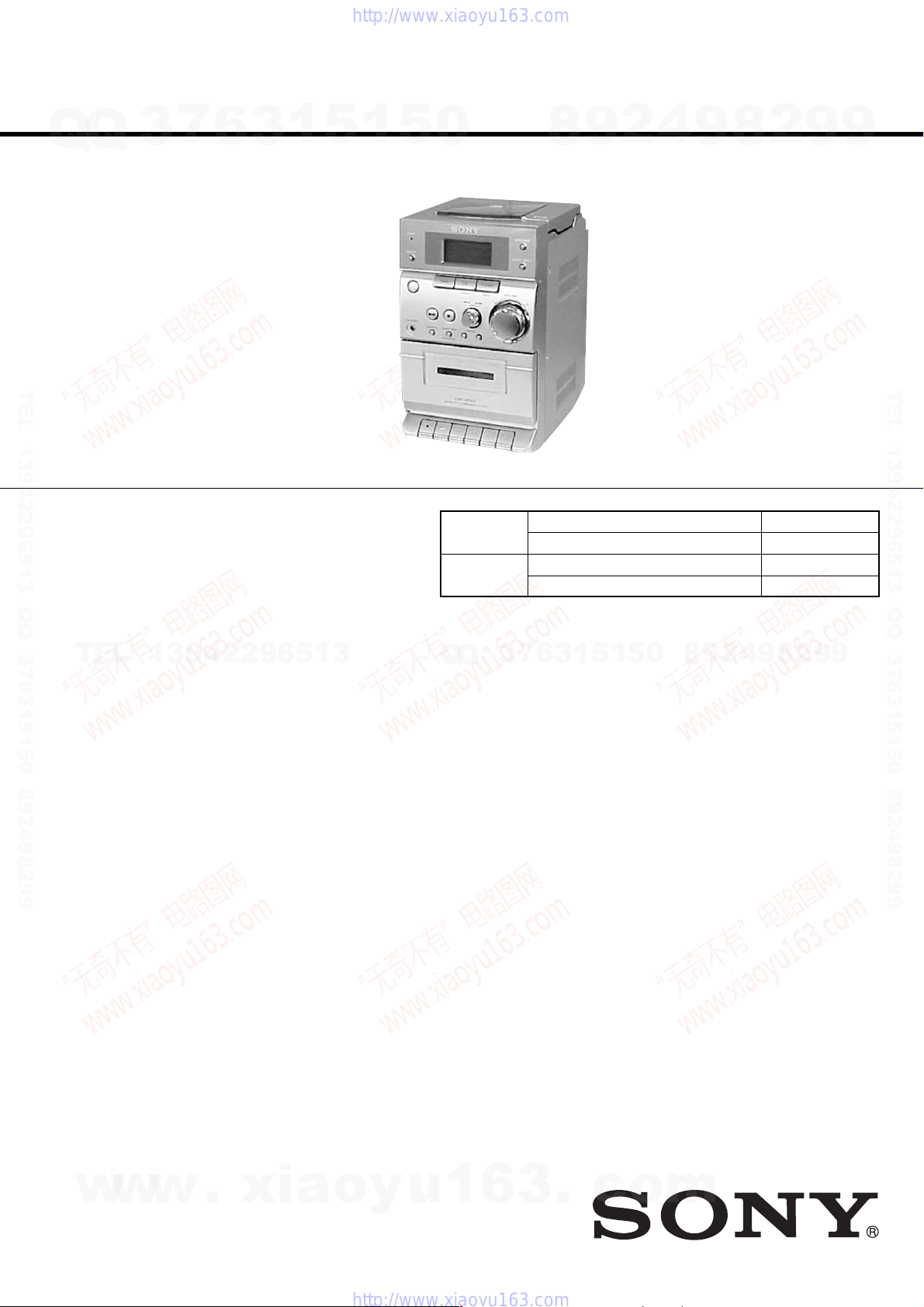
HCD-EP305 is the amplifler, CD
player , tape deck and tuner section in
CMT-EP305.
CD
SECTION
TAPE DECK
SECTION
4
2
9
8
Model Name Using Similar Mechanism HCD-EP30/EP40
CD Mechanism Type CS-21SC-1280
Model Name Using Similar Mechanism HCD-EP30/EP40
Tape T ransport Mechanism Type TCM125-2
9
2
8
AEP Model
9
9
TEL 13942296513 QQ 376315150 892498299
TEL
13942296513
Amplifier section
DIN power output (rated) 4.5 + 4.5 W
Continuous RMS power output (reference)
Music power output (reference)
Outputs
PHONES: Accepts headphones of
(stereo mini jack) 8 Ω or more
SPEAKER: Accepts impedance of 4 to
CD player section
System Compact disc and digital
Laser Semiconductor laser
Frequency response 20 Hz - 20 kHz (±0.5 dB)
Tape player section
Recording system 4-track 2-channel stereo
Frequency response 50 - 13 000 Hz (±3 dB),
SPECIFICATIONS
Q
Q
(4 Ω at 1 kHz, DIN)
6 + 6 W
(4 Ω at 1 kHz, 10% THD)
13 + 13 W
16 Ω
audio system
(λ=780 nm)
Emission duration:
continuous
using Sony TYPE I
cassette
2
9
8
0
5
1
5
1
3
6
7
3
Tuner section
FM stereo, FM/AM superheterodyne tuner
FM tuner section
Tuning range 87.5 - 108.0 MHz
Antenna FM lead antenna
Intermediate frequency 10.7 MHz
AM tuner section
Tuning range
Antenna Built-in ferrite bar antenna
Intermediate frequency 450 kHz
General
Power requirements 230 V AC, 50/60 Hz
Power consumption 30 W
Dimensions (w/h/d):
Mass: Approx. 2.9 kg
Design and specifications are subject to change
without notice.
531 -1 602 kHz
(with the interval set at
9 kHz)
0.5 W (in the standby
mode)
Approx. 145 × 240 × 252 mm
4
9
8
2
9
9
w
w
9-874-072-01
2002E1600-1
© 2002.05
w
.
xia
Sony Corporation
Home Audio Company
Published by Sony Engineering Corporation
o
y
u
1
COMPACT DISC DECK RECEIVER
6
3
.
c
o
m
HCD-EP305
TABLE OF CONTENTS
1. SERVICING NOTES······················································ 3
Q
Q
2. GENERAL ·········································································· 4
3. DISASSEMBLY ································································ 6
3-1. Front Panel Section ...................................................... 6
3-2. MAIN Board ................................................................ 7
3-3. Tape Mechanism Deck (TCM125-2) ........................... 7
3-4. POWER Board, Power Transformer ............................ 8
3-5. DISPLAY Board, HEADPHONE Board ..................... 8
3-6. CD Cabinet Section...................................................... 9
3-7. CD Mechanism Deck (CS-21SC-1280) ....................... 9
3-8. Cassette Lid................................................................ 10
4. MECHANICAL ADJUSTMENTS ····························· 11
TEL 13942296513 QQ 376315150 892498299
5. ELECTR ICAL ADJUSTMENTS ······························11
6. DIAGRAMS······································································ 15
6-1. Circuit Boards Location .............................................15
6-2. Block Diagrams..........................................................16
6-3. Printed Wiring Board MAIN Section........................ 19
6-4. Schematic Diagram MIAN Section (1/2)..................20
6-5. Schematic Diagram MIAN Section (2/2)..................21
6-6. Printed Wiring Board CASSETTE Section............... 22
6-7. Schematic Diagram CASSETTE Section ................. 22
6-8. Printed Wiring Board DISPLAY Section..................23
6-9. Schematic Diagram DISPLAY Section..................... 24
6-10. Printed Wiring Board POWER Section .................... 25
6-11. Schematic Diagram POWER Section .......................26
6-12. IC Pin Function Description ...................................... 29
TEL
7. EXPLODED VIEWS ······················································ 30
7-1. Cabinet Section .......................................................... 30
7-2. Front Panel Section -1................................................ 31
7-3. Front Panel Section -2................................................ 32
7-4. CD Cabinet Section.................................................... 33
7
3
13942296513
6
3
1
5
1
5
Notes on chip component replacement
0
•Never reuse a disconnected chip component.
• Notice that the minus side of a tantalum capacitor may be
damaged by heat.
Flexible Circuit Board Repairing
•Keep the temperature of soldering iron around 270˚C
during repairing.
• Do not touch the soldering iron on the same conductor of the
circuit board (within 3 times).
• Be careful not to apply force on the conductor when soldering
or unsoldering.
CAUTION
Use of controls or adjustments or performance of procedures
other than those specified herein may result in hazardous radiation
exposure.
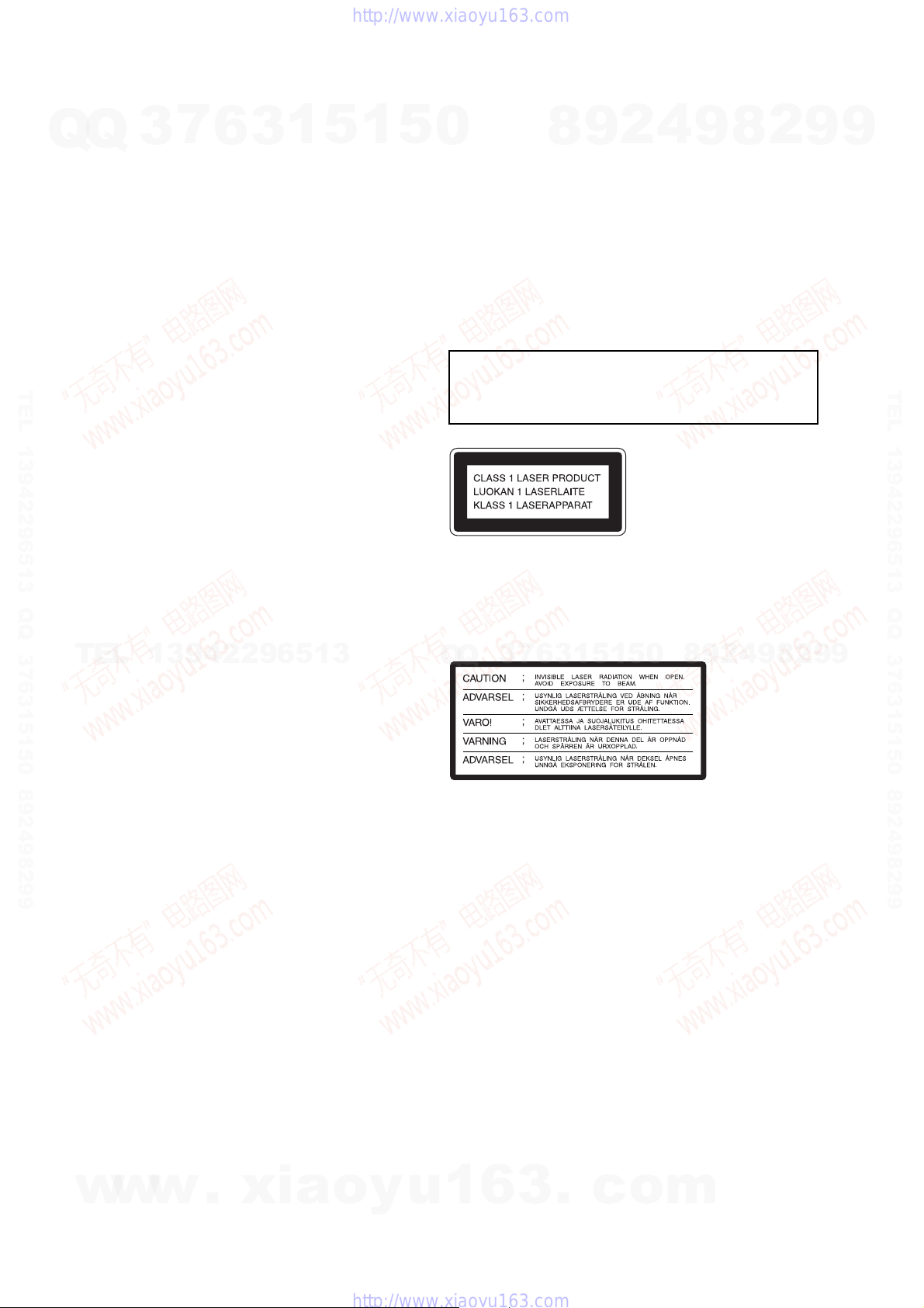
This appliance is classified as a CLASS 1 LASER product. The
CLASS 1 LASER PRODUCT MARKING is located on the rear
exterior.
The following caution label is located inside the unit.
7
3
Q
Q
8
6
3
9
1
5
2
1
5
4
0
9
8
9
8
2
4
2
9
8
9
2
9
9
TEL 13942296513 QQ 376315150 892498299
9
8. ELECTRICAL PARTS LIST ······································· 34
w
w
w
.
xia
o
y
SAFETY-RELATED COMPONENT WARNING!!
COMPONENTS IDENTIFIED BY MARK 0 OR DOTTED LINE WITH
MARK 0 ON THE SCHEMATIC DIAGRAMS AND IN THE PARTS
LIST ARE CRITICAL TO SAFE OPERATION. REPLACE THESE
u
1
6
3
.
c
o
COMPONENTS WITH SONY PARTS WHOSE PART NUMBERS
APPEAR AS SHOWN IN THIS MANUAL OR IN SUPPLEMENTS
PUBLISHED BY SONY.
m
2
SECTION 1
SERVICING NOTES
HCD-EP305
NOTES ON HANDLING THE OPTICAL PICK-UP
Q
TEL 13942296513 QQ 376315150 892498299
BLOCK OR BASE UNIT
Q
The laser diode in the optical pick-up block may suffer electrostatic
break-down because of the potential difference generated by the
charged electrostatic load, etc. on clothing and the human body.
During repair, pay attention to electrostatic break-down and also
use the procedure in the printed matter which is included in the
repair parts.
The flexible board is easily damaged and should be handled with
care.
NOTES ON LASER DIODE EMISSION CHECK
The laser beam on this model is concentrated so as to be focused on
the disc reflective surface by the objective lens in the optical pickup block. Therefore, when checking the laser diode emission,
observe from more than 30 cm away from the objective lens.
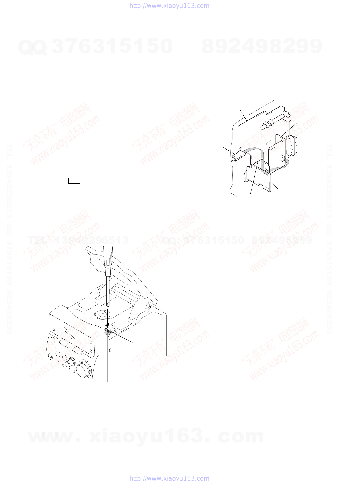
LASER DIODE AND FOCUS SEARCH OPERATION
CHECK
1. Press the ?/1 button to the power ON with no disc inserted
2. Open the lid for CD.
3. Turn on SW600 as following figure.
4. Confirm the laser diode emission while observing the objecting
7
3
and press the CD button.
lens. When there is no emission, Auto Power Control circuit or
Optical Pick-up is broken.
Objective lens moves up and down five times for the focus
search.
6
3
1
5
1
5
0
TO PREVENT ‘TAPE OSCILLATION SOUND AT VOLUME’
MAXIMUM SETTING (W/O TAPE)
Headphone wire dressing:
a.) Draw the wire from Main board to Headphone board along the
b.)The wire must be kept away from the top side of Cassette board
HEADPHONE
board
4
2
9
8
bottom side of heatsink.
at least 30 mm.
MAIN board
8
9
at least 30 mm
2
CASSETTE board
9
heatsink
9
TEL 13942296513 QQ 376315150 892498299
TEL
13942296513
SW600
Q
Q
3
7
6
3
1
5
1
5
0
8
9
2
4
9
8
2
9
9
w
w
w
.
xia
o
y
u
1
6
3
.
c
o
m
3
HCD-EP305
SECTION 2
GENERAL
This section is extracted
from instruction manual.
7
Q
Q
TEL 13942296513 QQ 376315150 892498299
3
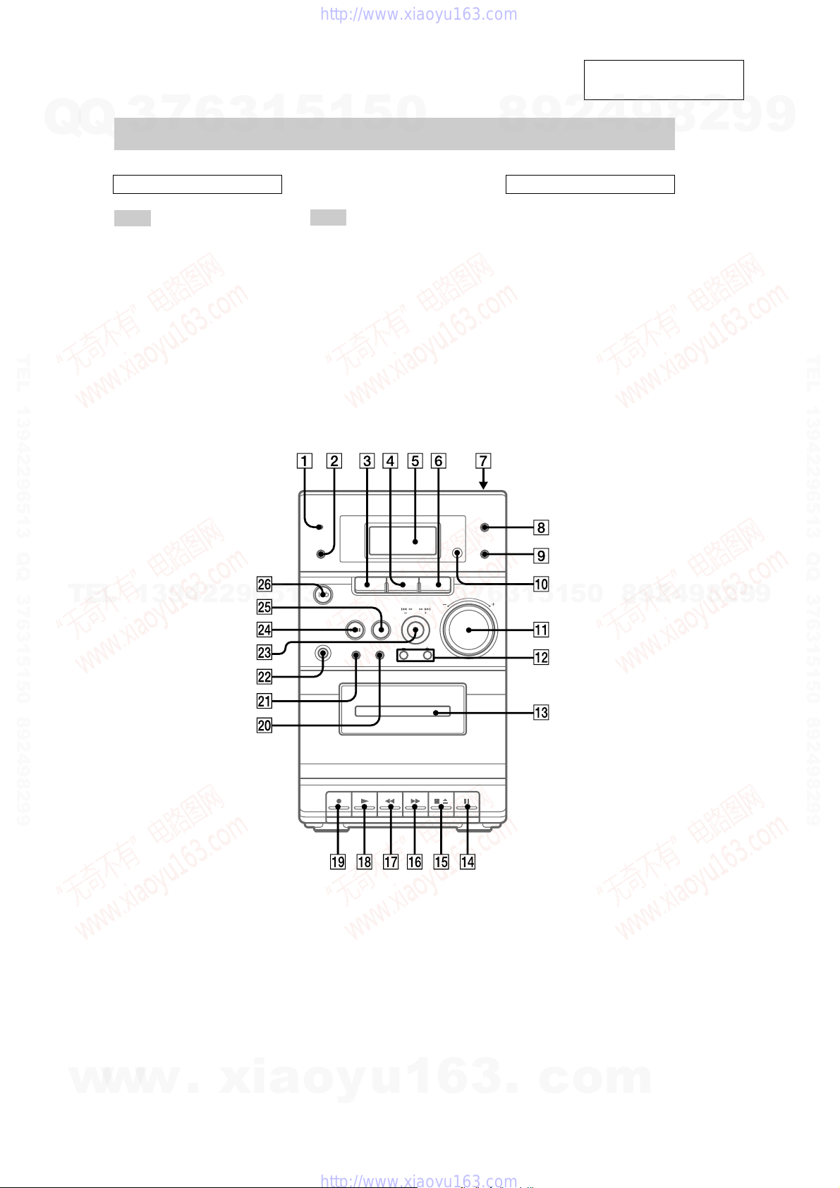
Main unit
ALPHABETICAL ORDER
A – P
Cassette compartment qd (12)
CD 4 (8, 9, 13)
Display Window 5 8, 9, 10)
ENTER/PGM 8, 9, 10, 14)
MEGA BASS (14)
MUSIC MENU 9 (14)
PHONES jack
PRESET +/– (10, 11)
6
w;
8
ws
qs
3
1
5
1
5
R – Z
Remote sensor q;
REPEAT (8)
SHUFFLE (8)
TAPE (12)
TIMER indicator (15)
TUNER (10, 11, 13)
TUNER MEM (10)
TUNING +/– (10, 11)
VOLUME control
2
wa
3
6
w;
wd
0
1
qa
4
2
9
8
BUTTON DESCRIPTIONS
@/1 (power) (6)
CD
.m /M> (go back/go
forward) (8, 9)
u (play/pause) (8, 9)
Z PUSH OPEN/CLOSE (8)
x (stop) (8)
TAPE
M (fast forward) (12)
X (pause) (12, 13)
N (play) (12)
z (recording) (13)
m (rewind) (12)
xZ (stop/eject) (12, 13)
wh
wd
wf
7
wg
qh
qf
qk
ql
qj
qg
9
8
2
9
9
TEL 13942296513 QQ 376315150 892498299
TEL
13942296513
Q
Q
3
7
6
3
1
5
1
5
0
8
9
2
4
9
8
2
9
9
4
w
w
w
.
xia
o
y
u
1
6
3
.
c
o
m
Q
Q
3
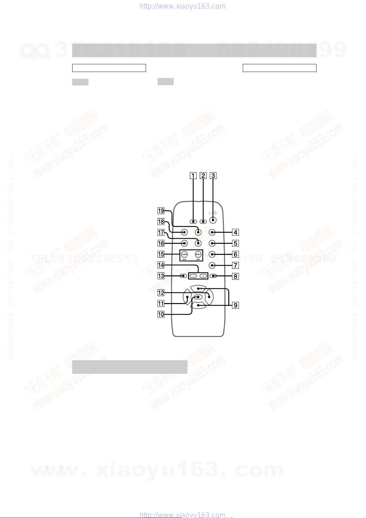
Remote control
7
6
3
1
5
1
5
0
8
9
2
4
9
HCD-EP305
2
8
9
9
ALPHABETICAL ORDER
A – P
CD/REMAIN (7, 8, 9, 13, 15,
16)
CLOCK/TIMER + (7, 14, 15)
CLOCK/TIMER – (7, 14, 15)
CLOCK/TIMER/SLEEP SET
(7, 14, 15)
MEGA BASS (14)
MUSIC MENU (14)
MUTING (14)
TEL 13942296513 QQ 376315150 892498299
PRESET +/– (10, 11)
ql
8
qd
1
qs
qa
q;
qf
R – Z
REPEAT (8)
SHUFFLE (8)
TAPE (12)
TIMER ON/OFF (15)
TUNER/BAND (10, 11, 13)
TUNER MEM/ENTER/PGM
TUNING + (10, 11)
TUNING – (10, 11)
VOL (volume) +/–
6
5
qk
2
4
(7, 9, 10, 14, 15)
8
qd
9
7
BUTTON DESCRIPTIONS
m (rewind) M (fast forward)
qg (8)
. (go back) > (go forward)
qg (8, 9)
u (play/pause) qh (8, 9)
@/1 (power) 3 (6)
x (stop) qj (8, 9, 12)
TEL 13942296513 QQ 376315150 892498299
TEL
13942296513
Setting the clock
1 Turn on the system.
2 Press CLOCK/TIMER/SLEEP SET on
the remote.
3 Press CLOCK/TIMER + or – on the
remote repeatedly to set the clock.
4 Press TUNER MEM/ENTER/PGM on the
remote.
The clock starts working.
Q
Q
3
7
6
3
1
5
1
5
0
8
9
2
4
9
8
2
9
9
w
w
To adjust the clock
Perform from step 2.
w
.
Note
The clock settings are canceled when you disconnect
the power cord or if a power failure occurs.
xia
o
y
u
1
6
3
.
c
o
m
5
t
HCD-EP305
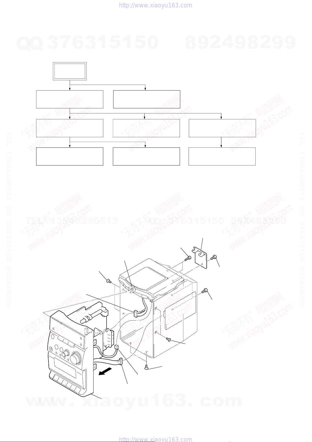
SECTION 3
DISASSEMBLY
• The equipment can be removed using the following procedure.
Q
Q
3
7
SET
6
3
1
5
1
5
0
8
9
2
4
9
8
2
9
9
FRONT PANEL SECTION
TEL 13942296513 QQ 376315150 892498299
Note : Follow the disassembly procedure in the numerical order given.
3-1. Front Panel Section
TEL
MAIN BOARD
TAPE MECHANISM DECK
(TCM125-2)
13942296513
CASSETTE LID
POWER BOARD,
POWER TRANSFORMER
DISPLAY BOARD,
HEADPHONE BOARD
3
Q
Q
3
two screws
(+BTP2.6
7
×
10)
6
CD CABINET SECTION
CD MECHANISM DECK
(CS-21SC-1280)
5
1
5
1
3
2
antenna cover cabine
0
8
9
2
4
9
8
2
9
TEL 13942296513 QQ 376315150 892498299
9
w
w
8
w
5
two screws
(+K3
connector
(CN203)
.
xia
6
claw
×
5)
7
9
connector
(CN402)
qa
front panel section
o
y
0
connector
(SW600)
u
1
5
two screws
(+K3
6
×
5)
3
5
two screws
(+K3
.
×
5)
c
1
screw
(+BVTP3
4
two screws
(+BVTP3
o
×
10)
×
m
10)
6
d
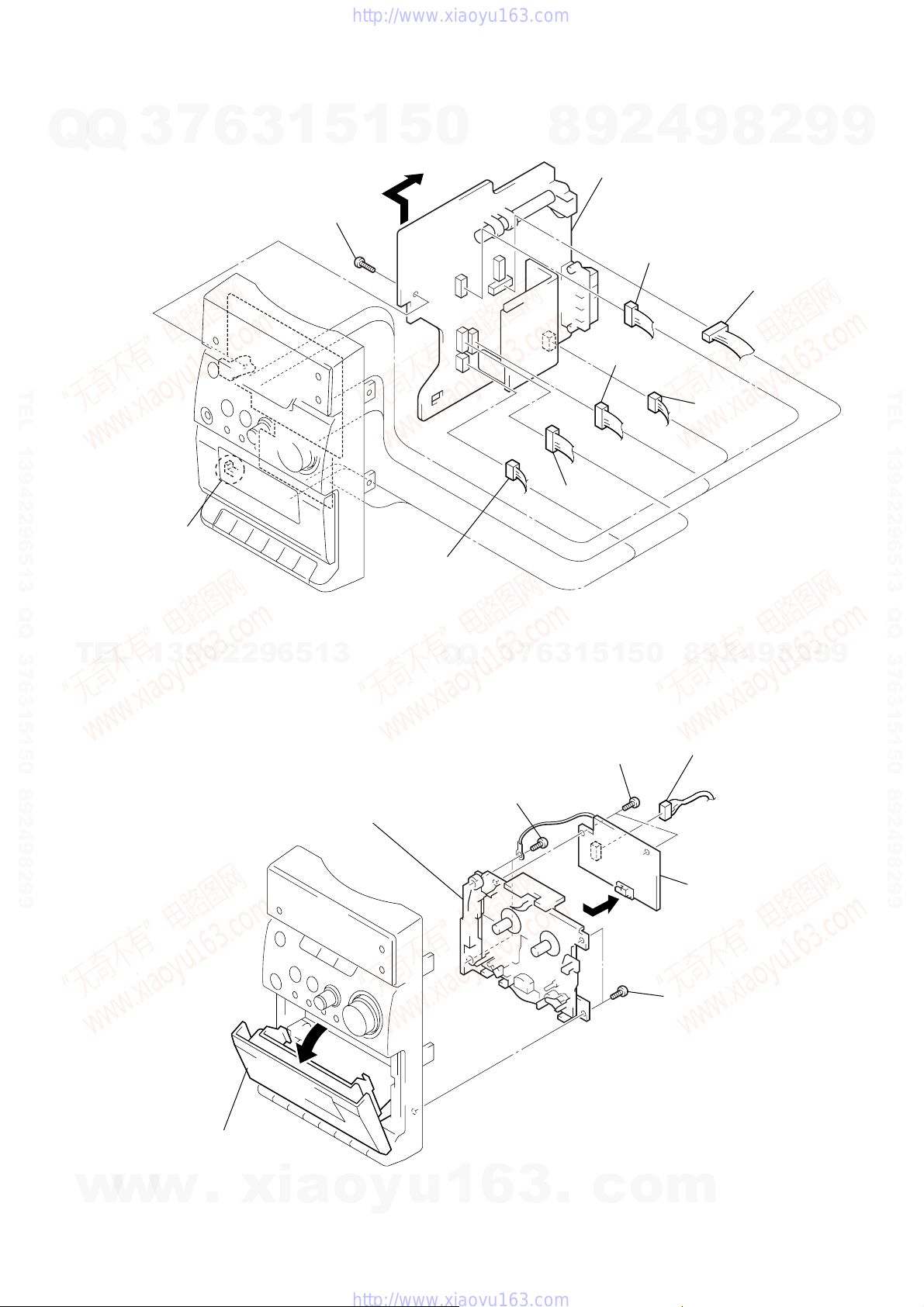
3-2. MAIN Board
7
Q
Q
TEL 13942296513 QQ 376315150 892498299
3
6
3
1
7
screw
(+BTP2.6 × 8)
5
1
9
5
0
8
9
0
4
2
MAIN board
2
4
connector
(CN302)
9
connector
(CN101)
3
8
1
connector
(CN301)
HCD-EP305
2
connector
(CN204)
9
9
TEL 13942296513 QQ 376315150 892498299
8
claw
TEL
13942296513
3-3. Tape Mechanism Deck (TCM125-2)
7
tape mechanism deck
6
connector
(CN202)
Q
Q
6
two screws
(+BVTP3
3
×
7
10)
6
5
connector
(CN201)
1
3
2
two screws
(+BTP2.6
5
3
1
5
×
6)
0
4
2
9
8
1
connector
(CN701)
4
CASSETTE boar
9
8
2
9
9
w
w
5
w
Open the cassette lid.
.
xia
o
y
u
1
6
3
.
c
o
6
two screws
(+BVTP3
m
×
10)
7
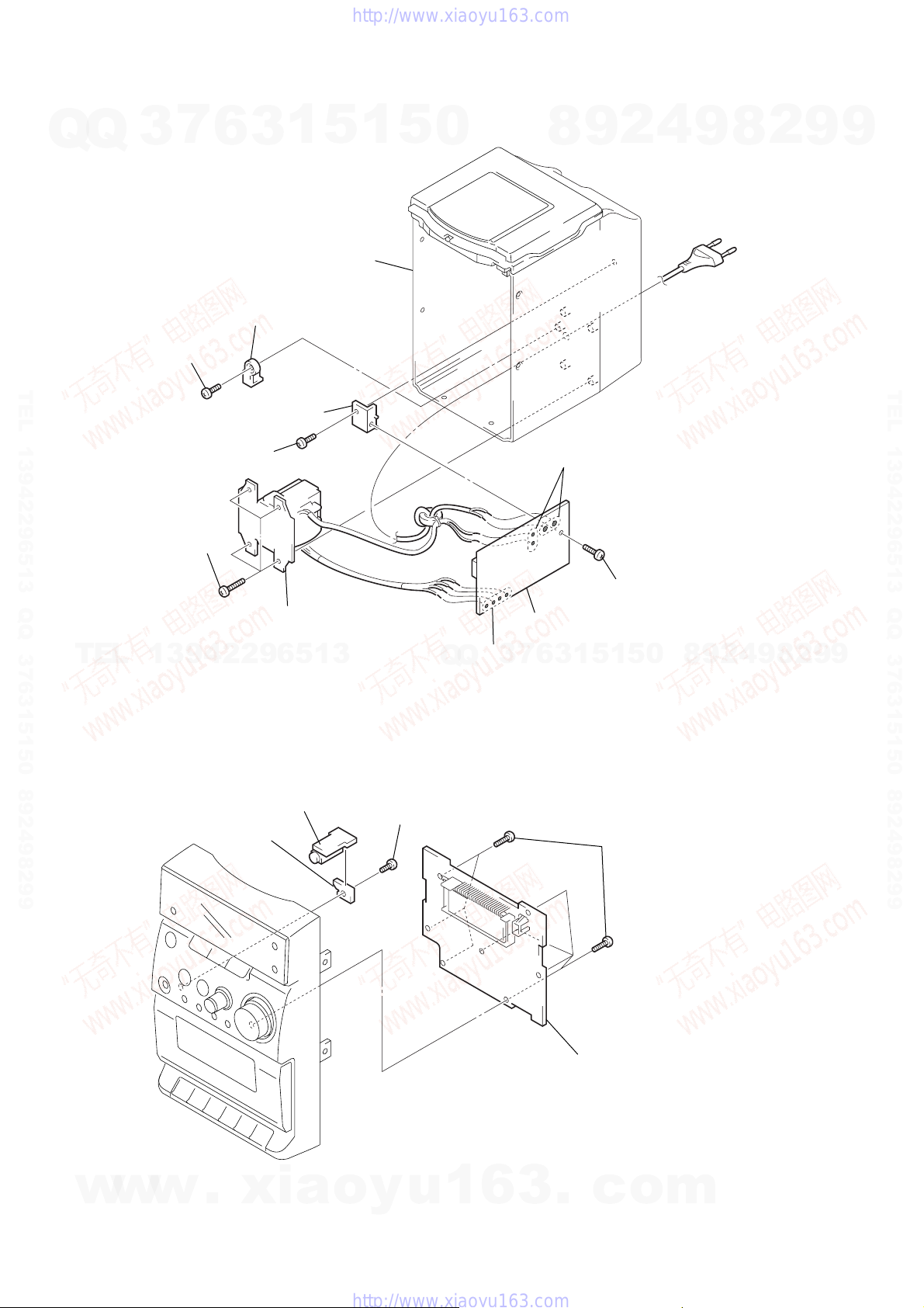
HCD-EP305
3-4. POWER Board, Power Transformer
Q
Q
3
1
screw
(+BVTP3
7
×
10)
6
2
AC cord holder
1
3
rear cabinet assy
5
1
5
0
8
9
2
4
9
8
2
9
9
TEL 13942296513 QQ 376315150 892498299
q;
power pwb mounting bkt
3
screw
(+BVTP3
4
four screws
(+BVTP3
TEL
3-5. DISPLAY Board, HEADPHONE Board
13942296513
5
×
10)
×
12)
6
power transformer
HEADPHONE board
4
reteiner board
3
screw
(+PTPWH2.6
8
Remove four solderings.
7
3
Q
Q
×
10)
5
7
Remove four solderings.
9
POWER board
1
5
1
3
6
1
screw
(+BTP2.6
8
0
5
seven screws
(+BTP2.6
×
×
10)
8)
9
2
4
9
8
2
9
TEL 13942296513 QQ 376315150 892498299
9
8
w
w
w
.
xia
o
y
u
1
6
3
2
.
DISPLAY board
c
o
m
)
Q
3-6. CD Cabinet Section
7
Q
3
6
1
3
2
CD cabinet section
5
1
5
0
8
9
2
1
4
9
two screws
(+BTP2.6
×
8
HCD-EP305
2
8
9
9
TEL 13942296513 QQ 376315150 892498299
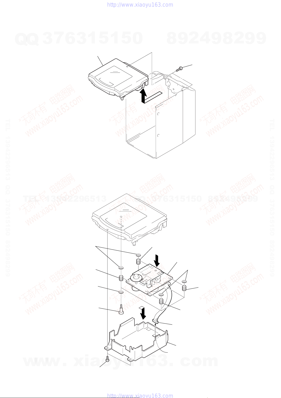
3-7. CD Mechanism Deck (CS-21SC-1280)
TEL
13942296513
7
two spring clamps
Q
Q
7
3
8
vibration proof rubber
(orange)
6
3
1
5
1
5
0
8
9
2
4
9
8
2
9
TEL 13942296513 QQ 376315150 892498299
9
w
w
8
vibration proof rubber
(pink)
6
5
w
.
four fiber washers
four pulley screws
xia
1
o
y
u
1
two screws
(BVTP3
×
10)
3
6
6
3
9
CD mechanism deck (CS-21SC-1280)
7
two spring clamps
8
vibration proof rubber
(orange)
8
vibration proof rubber
(pink)
2
Remove the connector.
4
CD cover housing
.
c
o
m
9
HCD-EP305
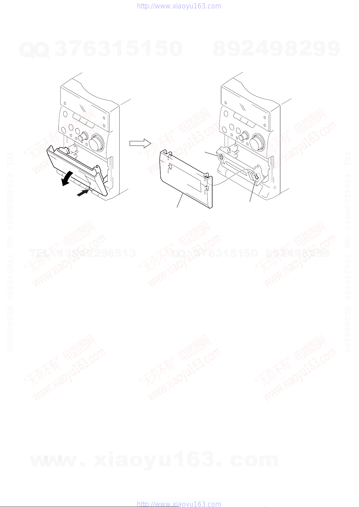
3-8. Cassette Lid
Q
Q
3
7
6
3
1
5
1
5
0
8
9
2
4
9
8
2
9
9
TEL 13942296513 QQ 376315150 892498299
2
1
Push stop/eject key.
TEL
13942296513
4
cassette lid
Q
Q
3
claw
3
7
6
3
1
5
1
5
3
0
claw
8
9
2
4
9
8
2
9
TEL 13942296513 QQ 376315150 892498299
9
10
w
w
w
.
xia
o
y
u
1
6
3
.
c
o
m
)
SECTION 4
MECHANICAL ADJUSTMENTS
HCD-EP305
SECTION 5
ELECTRICAL ADJUSTMENTS
PRECAUTION
Q
TEL 13942296513 QQ 376315150 892498299
1. Clean the following parts with a denatured-alcohol-moistened
Q
2. Demagnetize the record/playback head with a head
3. Do not use a magnetized screwdriver for the adjustments.
4. After the adjustments, apply suitable locking compound to the
5. The adjustments should be performed with the rated power
Torque Measurement
Tape Tension Measurement
TEL
7
3
swab :
demagnetizer. (Do not bring the head magnetizer close to the
erase head.)
parts adjusted.
supply voltage unless otherwise noted.
Mode Torque Meter Meter Reading
FWD CQ-102C (30 – 70 g•cm)
FWD
Back Tension
FF CQ-201B (more than 60 g•cm)
REW CQ-201B (more than 60 g•cm)
6
record/playback head pinch roller
erase head rubber belts
capstan idlers
13942296513
Mode Torque Meter Meter Reading
FWD CQ-403A more than 100 g
1
5
1
3
2.95 – 6.86 mN•m
(0.42 – 0.97 oz•inch)
0.15 – 5.39 mN•m
CQ-102C (1.5 – 5.5 g•cm)
(0.021 – 0.076 oz•inch)
more than 5.89 mN•m
(more than 0.83 oz•inch)
more than 5.89 mN•m
(more than 0.83 oz•inch)
(more than 3.53 oz)
5
0
Q
Q
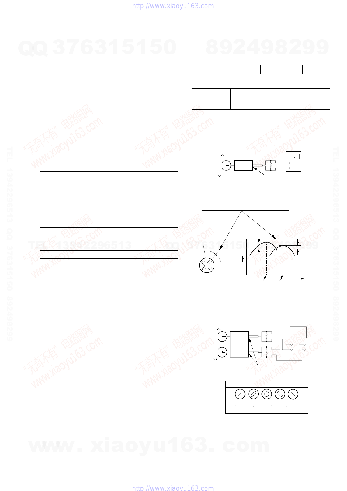
1. Setting
TAPE DECK SECTION 0 dB=0.775 V
Test tape
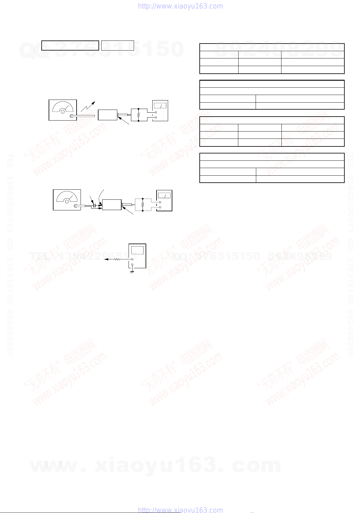
Record/Playback Head Azimuth Adjustment
Procedure:
1. Mode: Playback
2. Turn the adjustment screw and c heck output peaks. If the peaks
7
3
Screw
position
PRECAUTION
4
2
9
8
MEGA BASS switch : OFF
Type Signal Used for
WS-48A 3 kHz, 0 dB Tape Speed Adjustment
P-4-A063 6.3 kHz, –10 dB Head Azimuth Adjustment
test tape
P-4-A063
(6.3 kHz, –10 dB)
set
do not match for L-CH and R-CH, turn the adjustment screw
so that outputs match within 1dB of peak.
L-CH
peak
0
5
1
5
1
3
6
R-CH
peak
Output
level
9
32
HEADPHONE board
PHONES jack (JK401
within
1dB
2
9
8
L-CH
peak
8
Ω
4
R-CH
peak
2
level meter
+
–
2
8
9
9
within
9
1dB
Screw
position
9
9
TEL 13942296513 QQ 376315150 892498299
w
w
w
.
xia
o
y
u
1
3. Mode: Playback
test tape
P-4-A063
(6.3 kHz, –10 dB)
L-CH
set
R-CH
in phase
4. After the adjustments, apply suitable locking compound to the
parts adjusted.
6
3
.
c
o
32
32
HEADPHONE board
PHONES jack (JK401)
screen pattern
45
°
90
good wrong
m
Ω
Ω
135 °180
°
oscilloscope
V
+
+
–
–
°
H
11
HCD-EP305
r
L
)
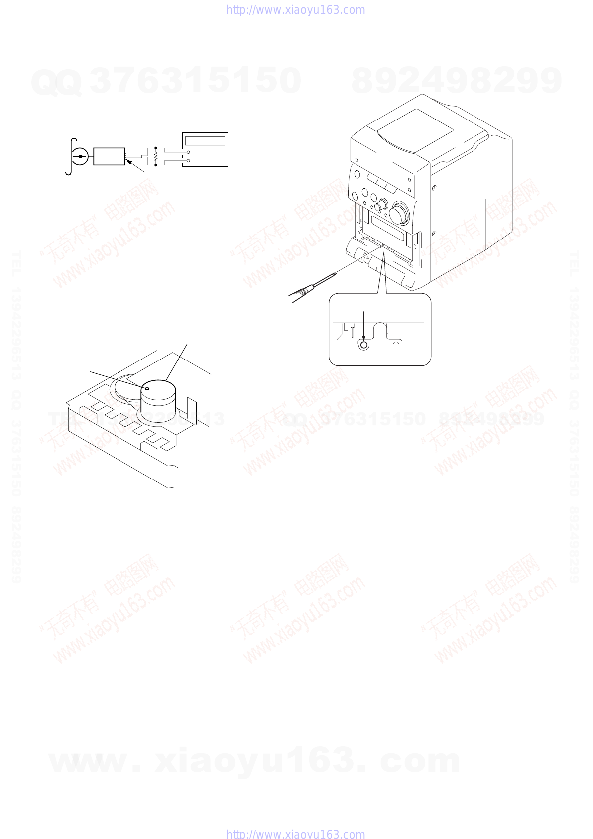
Tape Speed Adjustment
Setting:
Q
Q
Function: TAPE
test tape
WS-48A
(3 kHz, 0 dB)
Procedure:
1. Playback WS-48A (tape center) in the FWD state.
2. Adjsut the volume in CAPSTAN/REEL motor (M201) so that
the frequency counter reading becomes 3,000 Hz.
TEL 13942296513 QQ 376315150 892498299
Specified V alue: 2,910 to 3,090 Hz
3. Confirm that the frequency at the beginning and that at the end
of tape winding are between 2,955 to 3,045 Hz.
Adjustment Location:
3
set
7
6
32
HEADPHONE board
PHONES jack (JK401)
1
3
frequency counte
Ω
+
–
CAPSTAN/REE
motor (M201)
5
1
5
Adjustment Location: Record/Playback Head.
0
adjustment screw
8
9
2
4
9
8
2
9
9
TEL 13942296513 QQ 376315150 892498299
Tape Speed
Adjustment
TEL
13942296513
Q
Q
3
Note: Refer to “3-8. Cassette Lid” (see page 11
2
9
8
0
5
1
5
1
3
6
7
4
9
8
2
9
9
12
w
w
w
.
xia
o
y
u
1
6
3
.
c
o
m
)
)
HCD-EP305
TUNER SECTION 0 dB=1 µV
7
Q
Q
TEL 13942296513 QQ 376315150 892498299
3
[AM]
Setting:
Function : TUNER
Band switch : AM
AM RF signal
generator
30% amplitude
modulation by
400 Hz signal
Output level: as low as possible
[FM]
Setting:
Function : TUNER
Band switch : FM
FM RF signal
generator
22.5 kHz frequency
deviation by 400 Hz
signal
Output level: as low as possible
6
Put the lead-wire
antenna close to
the set.
0.01 µF
1
3
set
MAIN board
FM ANT
set
5
1
level meter
32
Ω
HEADPHONE board
PHONES jack (JK401
level meter
32
Ω
HEADPHONE board
PHONES jack (JK401
digital voltmeter
5
+
–
+
–
0
Adjustment Part Frequency Display Reading on Digital Voltmeter
Confirmation 531 kHz 1.5 ± 0.2 V
Adjustment Part Frequency Display Reading on Digital Voltmeter
Confirmation 108 MHz 7.0 ± 0.4 V
Adjustment Location: MAIN board (See page 14)
AM FREQUENCY COVERAGE ADJUSTMENT
4
2
9
8
T102 1,602 kHz 7.3 ± 0.3 V
AM TRACKING ADJUSTMENT
Adjust for a maximum reading on level meter
L110 603 kHz
TC102 1,404 kHz
FM FREQUENCY COVERAGE ADJUSTMENT
L104 87.6 MHz 2.1 ± 0.2 V
FM TRACKING ADJUSTMENT
Adjust for a maximum reading on level meter
L103 89.9 MHz
TC101 105.9 MHz
9
8
2
9
9
TEL 13942296513 QQ 376315150 892498299
TEL
•Repeat the procedures in each adjustment sev eral times, and the frequency
coverage and tracking adjustments should be finally done by the trimmer
capacitors.
MAIN board
13942296513
TP10 (FM VT)
TP11 (AM VT)
100 k
Ω
Q
Q
3
7
6
3
1
5
1
5
0
8
9
2
4
9
8
2
9
9
w
w
w
.
xia
o
y
u
1
6
3
.
c
o
m
13
 Loading...