

SONY HCD DX375 Service Manual
HCD-DX375
AUDIO POWER SPECIFICATIONS
POWER OUTPUT AND
TOTAL HARMONIC
DISTORTION
(FTC Output Power): FL/FR/SL/SR/C: 84 W/ch
3 ohm at 170 - 20,000 Hz,
0.7 % THD
SW: 160 W 1.5 ohm at 40 170 Hz, 0.7 % THD
Amplifier section
Surround mode (reference)
RMS output power, 10 %
THD
Front: 143 W + 143 W
(with SS-TS52)
Center*: 143 W
(with SS-CT51)
Surround*: 143 W + 143
W
(with SS-TS51)
Subwoofer*: 285 W
(with SS-WS52B)
*Depending on the sound field settings and the source,
there may be no sound output.
Inputs
TV, VCR (AUDIO IN) Sensitivity: 450/250 mV
AUDIO IN Sensitivity: 250/125 mV
Outputs (Analog)
Phones Accepts low-and high-
impedance headphones.
Super Audio CD/DVD system
Laser Semiconductor laser
(Super Audio CD/DVD:
λ = 650 nm)
(CD: λ = 790 nm)
Emission duration:
continuous
Signal format system NTSC
Harmonic distortion Less than 0.03 %
Tuner section
System PLL quartz-locked digital
synthesizer system
FM tuner section
Tuning range 87.5 – 108.0 MHz
(100 kHz step)
Antenna (aerial) FM wire antenna (aerial)
Antenna (aerial) terminals 75 ohms, unbalanced
Intermediate frequency 10.7 MHz
AM tuner section
Tuning range 530 – 1,710 kHz (with the
interval set at 10 kHz)
531 – 1,710 kHz (with the
interval set at 9 kHz)
Antenna (aerial) AM loop antenna (aerial)
Intermediate frequency 450 kHz
Video section
Outputs VIDEO: 1 Vp-p 75 ohms
S VIDEO:
Y: 1 Vp-p 75 ohms
C: 0.286 Vp-p 75 ohms
COMPONENT:
Y: 1 Vp-p 75 ohms
PB/CB, PR/CR: 0.7 Vp-p
75 ohms
HDMI OUT:
Type A (19 pin)
SERVICE MANUAL
Ver. 1.1 2006.04
HCD-DX375 is the amplifier, DVD/CD and tuner
section in DAV-DX375.
This system incorporates with Dolby*1 Digital and Dolby Pro Logic (II)
adaptive matrix surround decoder and the DTS*2 Digital Surround
System.
*1 Manufactured under license from Dolby Laboratories.
“Dolby,” “Pro Logic,” and the double-D symbol are trademarks of
Dolby Laboratories.
*2 Manufactured under license from Digital Theater Systems, Inc.
“DTS” and “DTS Digital Surround” are trademarks of Digital
Theater Systems, Inc.
US Model
Model Name Using Similar Mechanism HCD-DX255
Mechanism T ype CDM81C-DVBU101
Optical Pick-up Name
KHM-310CAB
9-887-160-02
2006D16-1
© 2006.04
Sony Corporation
Home Audio Division
Published by Sony Techno Create Corporation
SPECIFICATIONS
SUPER AUDIO CD/DVD RECEIVER
— Continued on next page —
HCD-DX375
r
General
Power requirements 120 V AC, 60 Hz
Power consumption On: 160 W
Dimensions (approx.) 430 × 86 × 418 mm
Mass (approx.) 5.2 kg (11 lb 8 oz)
Design and specifications are subject to change
without notice.
Standby: 0.3 W (at the
Power Saving mode)
1
(17 × 3
/4 × 16 3/4 inches)
(w/h/d) incl. projecting
parts
SAFETY CHECK-OUT
After correcting the original service problem, perform the following
safety check before releasing the set to the customer:
Check the antenna terminals, metal trim, “metallized” knobs, screws,
and all other exposed metal parts for AC leakage.
Check leakage as described below.
LEAKAGE TEST
The AC leakage from any exposed metal part to earth ground and
from all exposed metal parts to any exposed metal part having a
return to chassis, must not exceed 0.5 mA (500 microamperes.).
Leakage current can be measured by any one of three methods.
1. A commercial leakage tester, such as the Simpson 229 or RCA
WT -540A. Follow the manuf acturers’ instructions to use these
instruments.
2. A battery-operated AC milliammeter. The Data Precision 245
digital multimeter is suitable for this job.
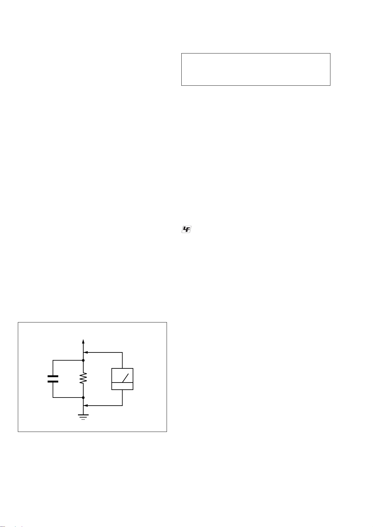
3. Measuring the voltage drop across a resistor by means of a
VOM or battery-operated AC v oltmeter. The “limit” indication
is 0.75 V, so analog meters must hav e an accurate low-v oltage
scale. The Simpson 250 and Sanwa SH-63Trd are examples
of a passive VOM that is suitable. Nearly all battery operated
digital multimeters that have a 2 V A C range are suitable. (See
Fig. A)
To Exposed Metal
Parts on Set
CAUTION
Use of controls or adjustments or performance of procedures
other than those specified herein may result in hazardous radiation
exposure.
Notes on chip component replacement
• Never reuse a disconnected chip component.
• Notice that the minus side of a tantalum capacitor may be
damaged by heat.
Flexible Circuit Board Repairing
• Keep the temperature of the soldering iron around 270 °C
during repairing.
• Do not touch the soldering iron on the same conductor of the
circuit board (within 3 times).
• Be careful not to apply force on the conductor when soldering
or unsoldering.
UNLEADED SOLDER
Boards requiring use of unleaded solder are printed with the leadfree mark (LF) indicating the solder contains no lead.
(Caution: Some printed circuit boards may not come printed with
the lead free mark due to their particular size)
: LEAD FREE MARK
Unleaded solder has the following characteristics.
• Unleaded solder melts at a temperature about 40 °C higher
than ordinary solder.
Ordinary soldering irons can be used but the iron tip has to be
applied to the solder joint for a slightly longer time.
Soldering irons using a temperature regulator should be set to
about 350 °C.
Caution: The printed pattern (copper foil) may peel away if
the heated tip is applied for too long, so be careful!
• Strong viscosity
Unleaded solder is more viscou-s (sticky, less prone to flow)
than ordinary solder so use caution not to let solder bridges
occur such as on IC pins, etc.
• Usable with ordinary solder
It is best to use only unleaded solder but unleaded solder may
also be added to ordinary solder.
AC
0.15 µF
1.5 k
Ω
Earth Ground
voltmete
(0.75 V)
Fig. A. Using an AC voltmeter to check AC leakage.
SAFETY-RELATED COMPONENT WARNING!!
COMPONENTS IDENTIFIED BY MARK 0 OR DOTTED LINE
WITH MARK 0 ON THE SCHEMATIC DIAGRAMS AND IN
THE PARTS LIST ARE CRITICAL TO SAFE OPERATION.
REPLACE THESE COMPONENTS WITH SONY PARTS WHOSE
PART NUMBERS APPEAR AS SHOWN IN THIS MANUAL OR
IN SUPPLEMENTS PUBLISHED BY SONY.
2

TABLE OF CONTENTS
HCD-DX375
1. SERVICING NOTE ................................................... 4
2. GENERAL ................................................................... 11
3. DISASSEMBLY
3-1. Disassembly Flow ........................................................... 14
3-2. Case, Front Panel Assy .................................................... 15
3-3. FL Board, SW Board....................................................... 16
3-4. JACK Board, LED Board ................................................ 16
3-5. DMB12 Board ................................................................. 17
3-6. I/O Board, Tuner.............................................................. 18
3-7. SPEAKER Board, D.C. Fan............................................ 18
3-8. MAIN Board.................................................................... 19
3-9. POWER Board ................................................................ 20
3-10. DVD Mechanism Deck (CDM81C-DVBU101) ............. 21
3-11. TRAY .............................................................................. 22
3-12. MOTOR Board M761 (LD/ST Motor),
M762 (BU U/D Motor) ................................................... 22
3-13. BASE UNIT (DVBU101) ................................................ 23
3-14. Optical Pick-up (KHM-310CAB) ................................... 23
3-15. Gear (Sub Tray 1), Gear (Sub Tray 2) ............................. 24
3-16. Lever Assy ....................................................................... 24
3-17. Stocker Section ................................................................ 25
3-18. Cam (Stocker).................................................................. 25
3-19. Gear (Stocker 3) .............................................................. 26
3-20. Rotary Encoder (MD)...................................................... 26
3-21. Gear (BU1) ...................................................................... 27
4. TEST MODE ............................................................... 28
5. ELECTRICAL ADJUSTMENT ............................. 32
6. DIAGRAMS
6-1. Block Diagram – RF Section –....................................... 34
6-2. Block Diagram – AMP Section – ................................... 35
6-3. Block Diagram – AUDIO Section – ............................... 36
6-4. Block Diagram – VIDEO Section – ............................... 37
6-5. Block Diagram – POWER Section –.............................. 38
6-6. Printed Wiring Board – DMB12 Board (Side A) – ......... 39
6-7. Printed Wiring Board – DMB12 Board (Side B) – ......... 40
6-8. Schematic Diagram – DMB12 Board (1/7) –................. 41
6-9. Schematic Diagram – DMB12 Board (2/7) –................. 42
6-10. Schematic Diagram – DMB12 Board (3/7) –................. 43
6-11. Schematic Diagram – DMB12 Board (4/7) –................. 44
6-12. Schematic Diagram – DMB12 Board (5/7) –................. 45
6-13. Schematic Diagram – DMB12 Board (6/7) –................. 46
6-14. Schematic Diagram – DMB12 Board (7/7) –................. 47
6-15. Printed Wiring Board – MAIN Board (Side A) – ............ 48
6-16. Printed Wiring Board – MAIN Board (Side B) –............ 49
6-17. Schematic Diagram – MAIN Board (1/6) – ................... 50
6-18. Schematic Diagram – MAIN Board (2/6) – ................... 51
6-19. Schematic Diagram – MAIN Board (3/6) – ................... 52
6-20. Schematic Diagram – MAIN Board (4/6) – ................... 53
6-21. Schematic Diagram – MAIN Board (5/6) – ................... 54
6-22. Schematic Diagram – MAIN Board (6/6) – ................... 55
6-23. Printed Wiring Board – I/O Board – ............................... 56
6-24. Schematic Diagram – I/O Board – ................................. 57
6-25. Printed Wiring Boards – PANEL Section –..................... 58
6-26. Schematic Diagram – PANEL Section – ........................ 59
6-27. Printed Wiring Board – SPEAKER Board – ................... 60
6-28. Schematic Diagram – SPEAKER Board – ...................... 60
6-29. Printed Wiring Boards – CD MECHANISM Section – . 61
6-30. Schematic Diagram – CD MECHANISM Section – ..... 62
6-31. Printed Wiring Board – POWER Board – ....................... 63
6-32. Schematic Diagram – POWER Board –........................ 64
7. EXPLODED VIEWS
7-1. Overall Section................................................................ 78
7-2. Front Panel Section ......................................................... 79
7-3. Chassis Section................................................................ 80
7-4. DVD Mechanism Deck Section-1
(CDM81C-DVBU101) .................................................... 81
7-5. DVD Mechanism Deck Section-2
(CDM81C-DVBU101) .................................................... 82
7-6. DVD Mechanism Deck Section-3
(CDM81C-DVBU101) .................................................... 83
7-7. Base Unit (DVBU101) .................................................... 84
8. ELECTRICAL PARTS LIST .................................. 85
3
HCD-DX375
SECTION 1
SERVICING NOTE
NOTES ON HANDLING THE OPTICAL PICK-UP BLOCK
OR BASE UNIT
The laser diode in the optical pick-up block may suffer electrostatic
break-down because of the potential difference generated by the
charged electrostatic load, etc. on clothing and the human body.
During repair, pay attention to electrostatic break-down and also
use the procedure in the printed matter which is included in the
repair parts.
The flexible board is easily damaged and should be handled with
care.
NOTES ON LASER DIODE EMISSION CHECK
The laser beam on this model is concentrated so as to be focused on
the disc reflective surface by the objective lens in the optical pickup block. Therefore, when checking the laser diode emission,
observe from more than 30 cm away from the objective lens.
LASER DIODE AND FOCUS SEARCH
1. Open the cover and turn POWER on with no disc inserted.
2. Confirm that the following operation is performed while
observing the objecting lens.
1) Confirm that laser beam is spread.
2) Up and down motion of the objective lens. (3 times)
DISC TRA Y LOCK
The disc tray lock function for the antitheft of an demonstration
disc in the store is equipped.
Setting Procedure :
1. Press the ?/1 button to turn the set on.
2. Press the [FUNCTION] button to set DVD function.
3. Insert a disc.
4. Press the
x button and the A button simultaneously for five
seconds.
5. The message “LOCKED” is displayed and the tray is locked.
Releasing Procedure :
1. Press the x button and the A button simultaneously for fiv e
seconds again.
2. The message “UNLOCKED” is displayed and the tray is
unlocked.
Note 1: When “LOCKED” is displayed, the tray lock is not released by
Note 2: Incorrect operations may be performed if the test mode ia not
Note 3: If the disc tray does not open and the message “LOCKED”
turning power on/off with the ?/1 button.
entered properly.
In this case, press the ?/1 button to turn the power off, and
retry to enter the test mode.
appears, press the x button and the A button simultaneously
for seconds or longer.
Then remove your fingers from the above stick and the button.
The message “UNLOCKED” appears for 2 seconds and the disc
tray opens.
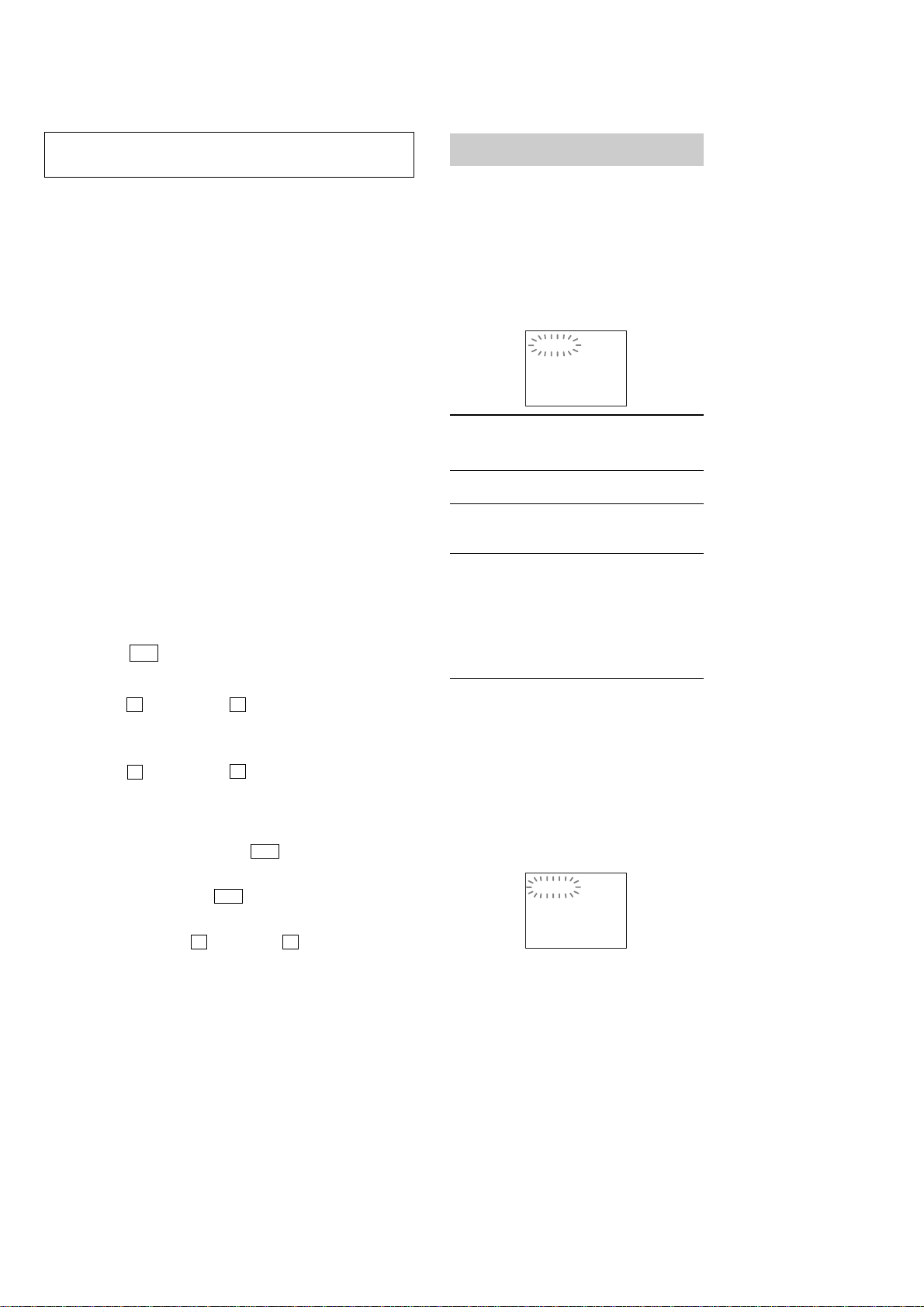
Self-diagnosis Function
(When letters/numbers appear in the
display)
When the self-diagnosis function is activated to
prevent the system from malfunctioning, a 5character service number (e.g., C 13 50) with a
combination of a letter and 4 digits appears on
the screen and the front panel display. In this
case, check the following table.
C:13:50
First 3
characters of
the service
number
C 13 The disc is dirty.
C 31 The disc is not inserted correctly.
E XX
(xx is a number)
When displaying the version
number on the screen
When you turn on the system, the version
number [VER.X.XX] (X is a number) may
appear on the screen. Although this is not a
malfunction and for Sony service use only,
normal system operation will not be possible.
Turn off the system, and then turn on the system
again to operate.
Cause and/or corrective action
,Clean the disc with a soft cloth
,Restart the system, then re-insert
the disc correctly.
To prevent a malfunction, the
system has performed the selfdiagnosis function.
,Contact your nearest Sony
dealer or local authorized Sony
service facility and give the 5character service number.
Example: E 61 10
VER.X.XX
Note on DMB12 board replacement
New part of EEP ROM (IC103, IC706) on the DMB12 board cannot be
used. Therefore, if the mounted DMB12 board (A-1148-813-A) is replaced,
exchange new EEP ROM (IC103, IC706) with that used before the
replacement.
4
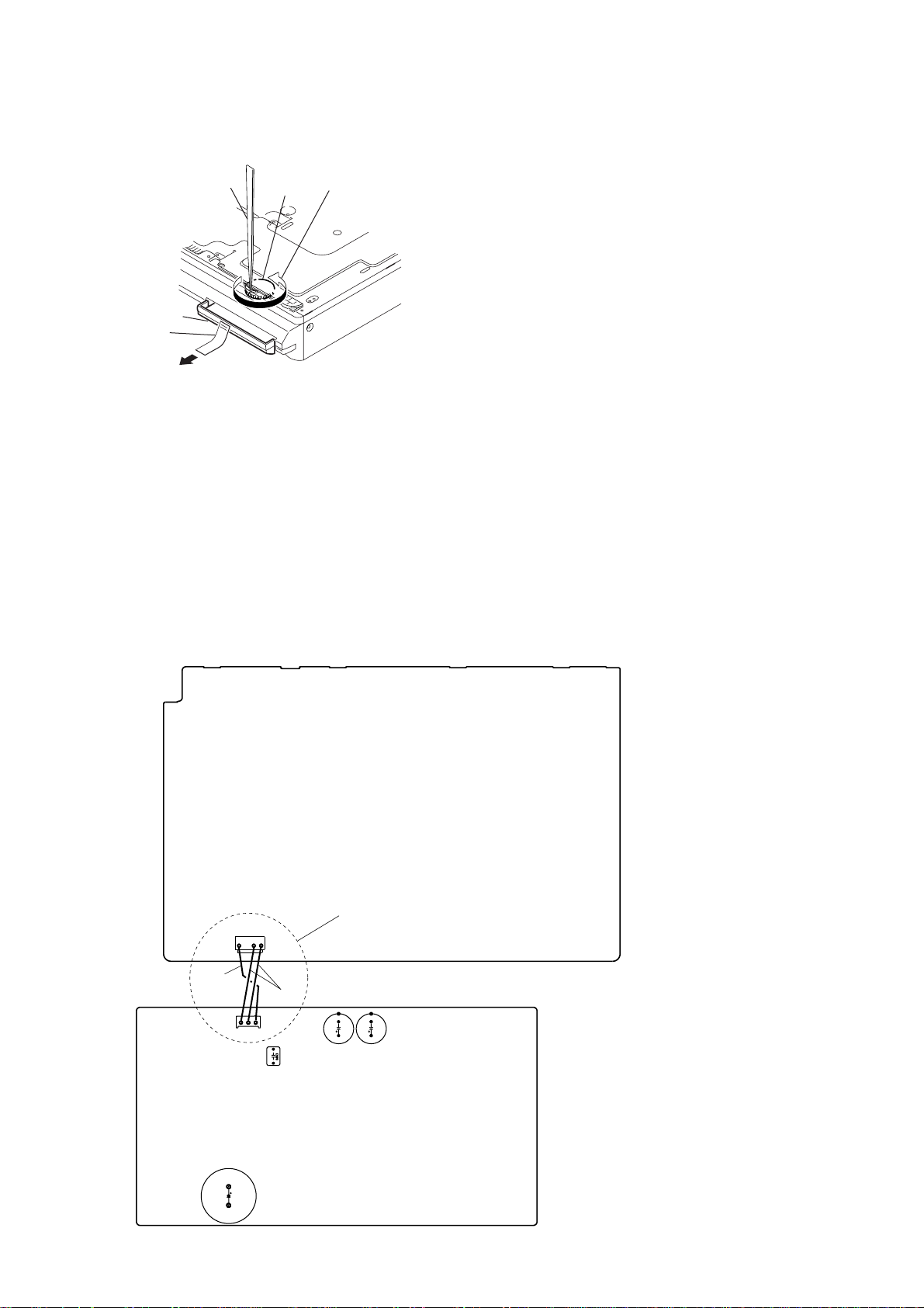
HOW TO OPEN THE DISC TABLE WHEN POWER SWITCH TURNS OFF
HCD-DX375
tweezers
DVD lid
tape
2
Attach an adhesive tape on the DVD LID and draw it out.
gear
1
Insert tip of tweezers through the hole
of bottom plate, and roate the gear in
the counter-clockwise direction.
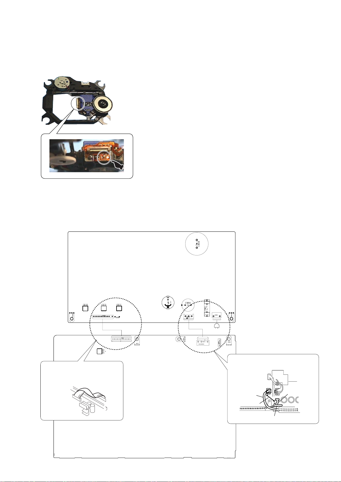
Discharge the charged electricity in capacitors to prevent electric shock as follows
When disassembling the machine, be sure to discharge the charged electricity in the following capacitors.
Use a resistor of 800 ohms, 2 Watts for discharging the following capacitors.
POWER board
C903 : 600V
C932, C933, C939, CN902 : 30V
MAIN board
CN3002 : 30 V
MAIN BOARD
POWER BOARD
BLACK
CN902
CN3002
C939
RED
*
Connect the specified resistor
between black and red leads
C933 C932
C903
5
HCD-DX375
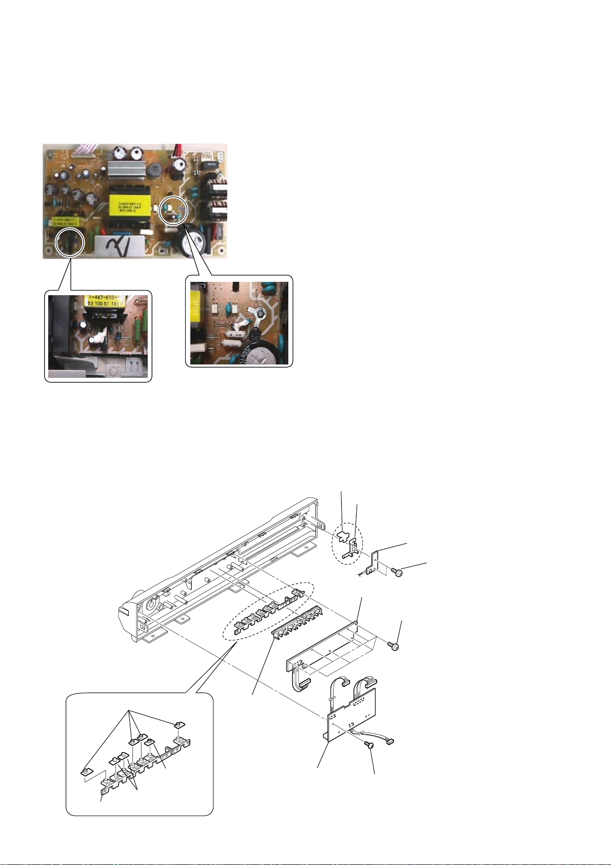
Fix the capacitors with adhesive agent as follows
Fixing the capacitors with adhesive agent is required by the safety regulation.
Be sure to fix the capacitors with adhesive agent when part or circuit board is replaced.
POWER BOARD
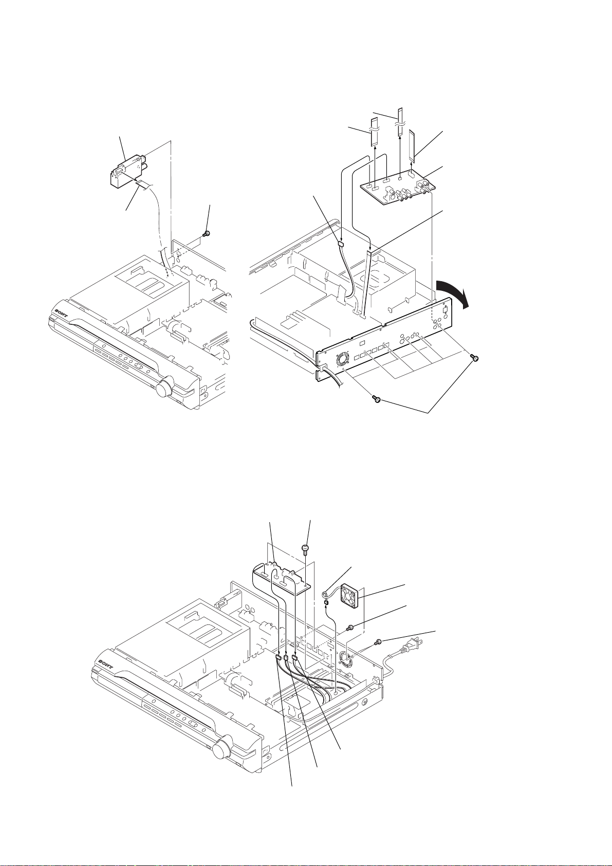
Precaution when replacing the CAP
Please apply the adhesive agent to the BUTTON BASE (PLAY) when replacing the CAP (PLAY) or CAP (FUNC) or CAP (AMS).
Please apply the adhesive agent to the BUTTON BASE (POWER) when replacing the CAP (POWER).
CAP (POWER)
BUTTON BASE (POWER)
SW board
s
crews
(+BVTP 2.6)
LED board
screws (+BVTP 2.6)
CAP (FUNK)
button (disk),
indicator (disk)
CAP (PLAY)
CAP (AMS)
BUTTON BASE (PLAY)
JACK board
screw (+BVTP 2.6)
6
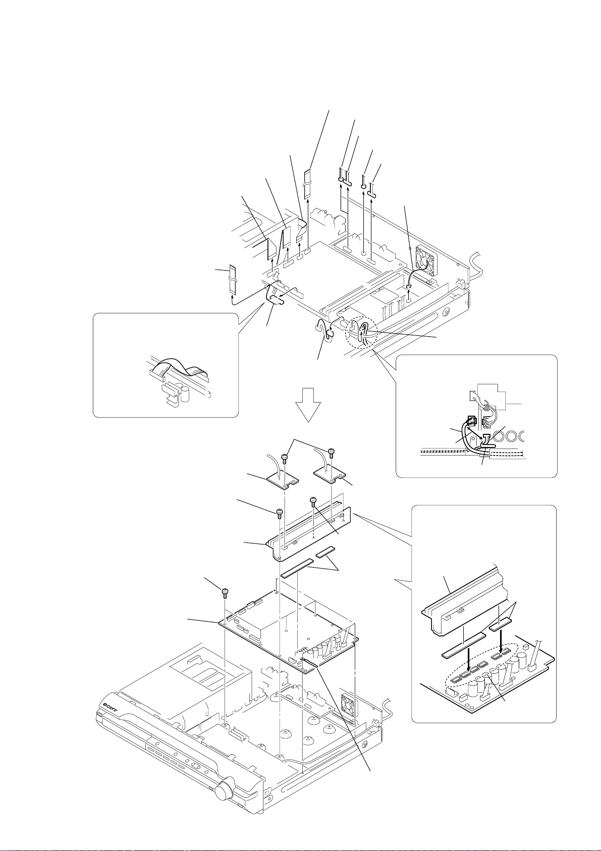
PRECAUTION WHEN INSTALLING A NEW OP UNIT /
MAIN BOARD
POWER BOARD
Precaution on the connector processing of the POWER board.
AC IN
13
1
12
After twist the harness once,
install the connector.
POWER board
MAIN board
IC504
CN506
CN3002
CN3001
CN902
CN901
CN904
IC941
IC942
IC943
When re-assembling, leave 30 mm between
harnesses A and B for safety.
harnesses A
harnesses B
clamp
30mm
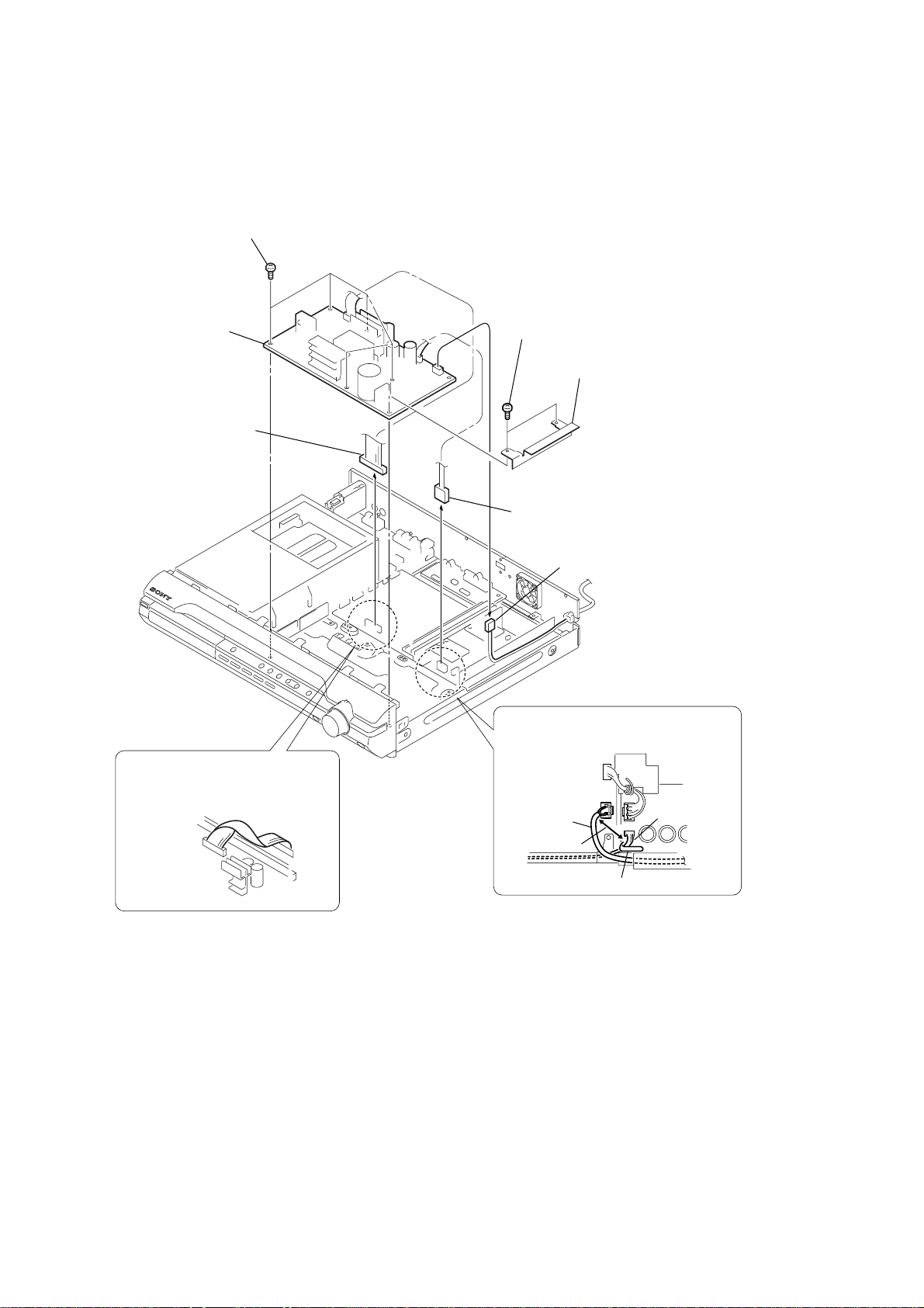
PRECAUTION BEFORE UNSOLDERING THE STATIC ELECTRICITY
PREVENTION SOLDER BRIDGE
HCD-DX375
When installing a new OP unit, be sure to connect the flexible printed circuit board first of all before removing the static
electricity prevention solder bridge by unsoldering. Remove the static electricity prevention solder bridge by unsoldering
after the flexible printed circuit board has already been connected.
(Do not remove nor unsolder the solder bridge as long as the OP unit is kept standalone.)
7
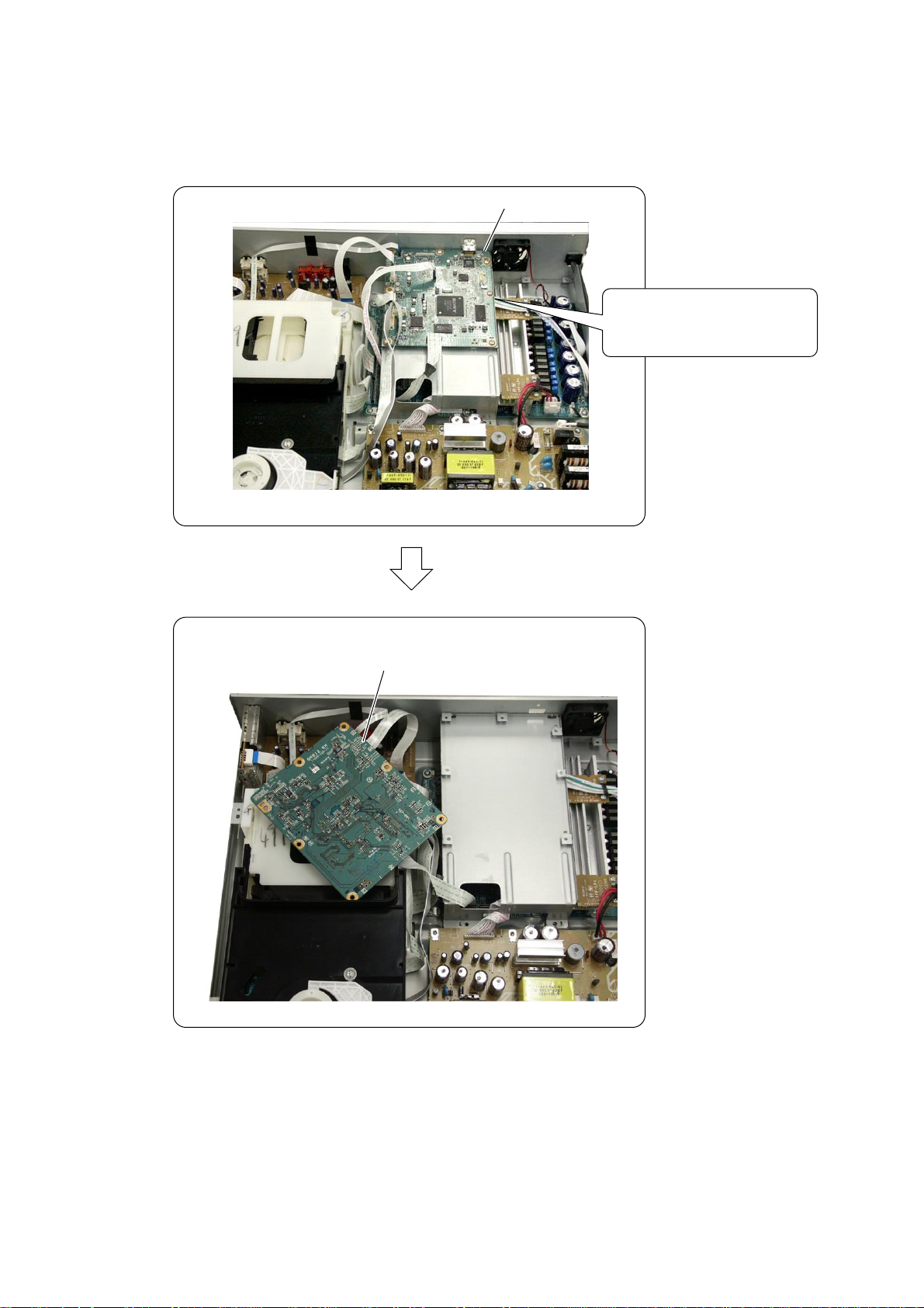
HCD-DX375
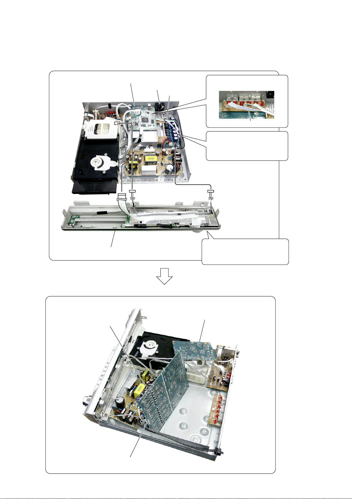
• DMB12 board service position
DMB12 board
Remove the DMB12 board once.
Then create the service position.
DMB12 board
8
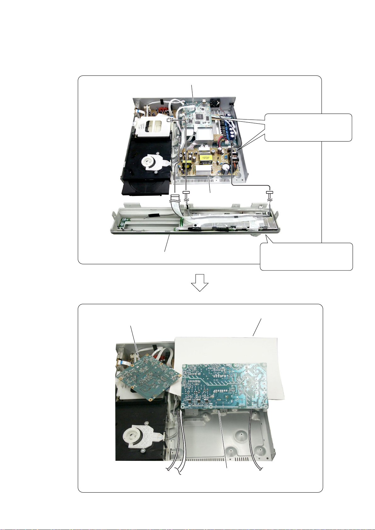
•POWER board service position
HCD-DX375
DMB12 board
Remove the DMB12 board and
POWER board once.
Then create the service position.
POWER board
DMB12 board
Front panel assy
Connect the flexible cable and
harnesses from the front panel assy.
Inshuration sheet
POWER board
9
HCD-DX375
• MAIN board service position
DMB12 board, bracket (HDMI)
D.C.fan
Front panel assy
Remove the three connectors of
the SPEAKER board.
MAIN board
SPEAKER board
Remove the DMB12 board ,
bracket (HDMI), D.C.fan and the
MAIN board once.
Then create the service position.
Connect the flexible cable and
harnesses from the front panel assy.
10
DMB12 board
D.C.fan
MAIN board
Front panel
SECTION 2
GENERAL
HCD-DX375
This section is extracted
from instruction manual.
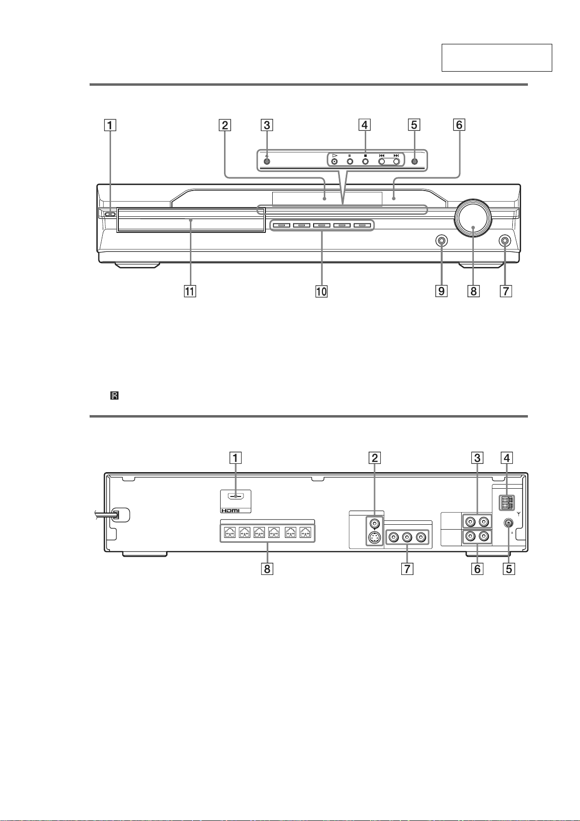
A "/1 (on/standby) (30)
B Front panel display (93)
C A (open/close) (30)
D Disc operation (30)
E FUNCTION (30)
F (remote sensor) (9)
Rear panel
(DVD ONLY)
OUT
SPEAKER
FRONT R FRONT L SUR R SUR LCENTER WOOFER
A HDMI OUT jack (24)
B MONITOR OUT (S VIDEO/VIDEO) jacks
(24)
C TV (AUDIO IN R/L) jacks (28)
D AM terminal (13)
G PHONES jack (30)
H VOLUME control (30)
I AUDIO IN/A.CAL MIC jack (19, 32)
J DISC 1-5 (30)
K Disc tray (30)
ANTENNA
MONITOR OUT
VIDEO
S VIDEO
(DVD ONLY)
COMPONENT VIDEO OUT
YPB/CBPR/C
(DVD ONLY)
R
VCR
RLAUDIO IN
TV
RLAUDIO IN
COAXIAL
FM
E COAXIAL FM 75Ω jack (13)
F VCR (AUDIO IN R/L) jacks (28)
G COMPONENT VIDEO OUT jacks (24)
H SPEAKER jacks (13)
AM
75
11
HCD-DX375
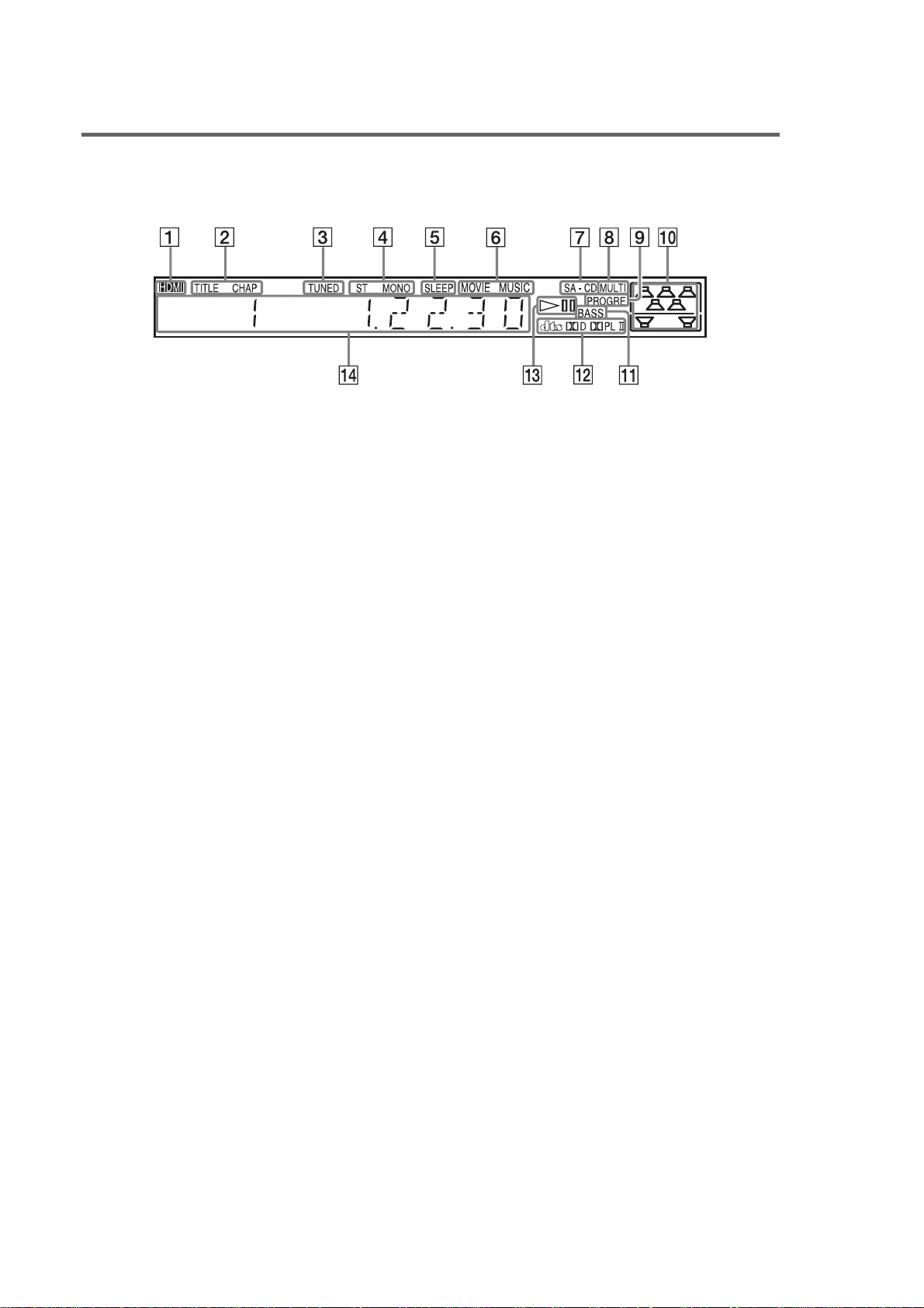
Front panel display
About the indications in the front panel display
A Lights up when the HDMI OUT jack is
correctly connected to HDCP (highbandwidth digital content protection)
compliant device with HDMI or DVI
(digital visual interface) input. (24)
B Lights up when the time information of
a title or chapter appears in the front
panel display. (DVD only) (46)
C Lights up when a station is received.
(Radio only) (58)
D Monaural/Stereo effect (Radio only)
(58)
E Lights up when the sleep timer is set.
(63)
F Lights up when the music or movie
mode is selected. (Except for JPEG)
(33)
G Lights up when Super Audio CD is
loaded.
H Lights up during MULTI channel
playback. (Super Audio CD only) (49)
I Lights up when the system outputs
progressive signals (DVD function
only). (26)
J Indicates the selected [SPEAKER
FORMATION]. (67)
K Lights up when the DYNAMIC BASS is
selected. (62)
L Current surround format (Except for
JPEG and Super Audio CD)
M Playing status (DVD function only)
N Displays system’s status such as
chapter, title, or track number, time
information, radio frequency, playing
status, sound field, etc.
12
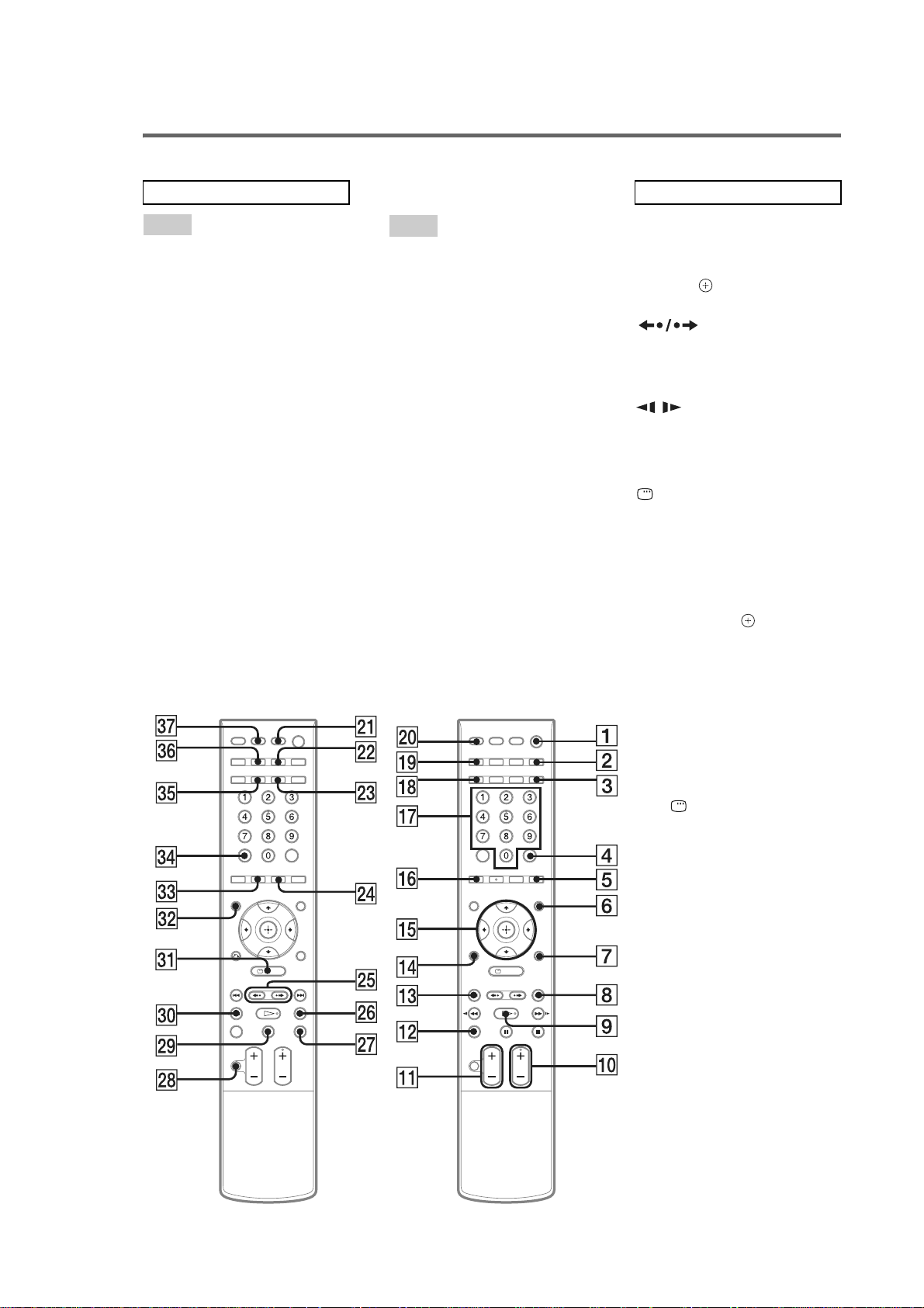
Remote control
HCD-DX375
ALPHABETICAL ORDER
A – O
AMP MENU3) 7 (22, 32, 61, 63,
98)
ANGLE 5 (48)
AUDIO
2)
ed (44)
CLEAR ef (37, 58, 61, 72)
D.TUNING wf (58)
DISC SKIP qs (30)
DISPLAY 2 (46, 59)
DYNAMIC BASS 3 (62)
ENTER
1)
4 (19, 22, 32, 37, 57,
64)
FUNCTION +/–
2)
0 (26, 30, 32,
39, 57, 67)
MENU 6 (43, 57)
MOVIE/MUSIC wd (33)
MUTING wk (30)
Number buttons
2)
qj (37, 58, 60,
64)
P – Z
PICTURE NAVI qh (38, 61)
PRESET +/– 8 qd (58)
PROGRESSIVE qk (26)
SLEEP eh (63)
SA-CD/CD ws (49)
SOUND FIELD eg (34)
SUBTITLE wf (48)
THEATRE SYNC wa (61)
TOP MENU es (43)
TUNING +/– wh e; (57)
TV w; (60)
TV CH +/–
2)
0 (60)
TV VOL +/– qa (60)
TV/VIDEO ql (60)
VOLUME +/–
qa (30, 58, 78)
BUTTON DESCRIPTIONS
[/1 (on/standby) 1 (19, 22, 30,
39, 58)
TV [/1 (on/standby) ej (60)
3)
C/X/x/c/
qg (19, 22, 32, 37,
57, 64)
REPLAY/
ADVANCE wg (30)
./> qd 8 (30)
m/M e; wh (36)
/ e; wh (36)
H (play)
2)
9 (30, 39, 65)
x (stop) wj (31, 39, 64)
X (pause) wl (31)
DISPLAY
3)
ea (20, 37, 64,
94)
O RETURN
3)
qf (38)
-/-- ef (60)
1)
The ENTER button is the same
function as the button.
2)
The H, number 5, AUDIO, and
FUNCTION + (TV CH +)
buttons have tactile dots. Use
the tactile dots as references
when operating the system.
3)
After pressing the TV button w;,
you can control the menu on a
Sony TV. On the menu screen,
the DISPLAY button ea
doubles as the MENU button,
and the AMP MENU button 7
double as the TOOLS button.
Note that depending on the
component, you ma y not be able
to use some or all of the buttons.
13
HCD-DX375
SECTION 3
DISASSEMBLY
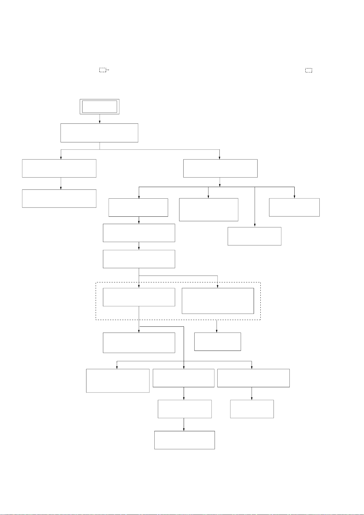
3-1. DISASSEMBLY FLOW
•This set can be disassembled in the order shown below.
•The dotted square with arrow ( ) prompts you to move to the next job when all of the works within the dotted square ( ) are
completed.
SET
3-2.CASE, FRONT PANEL ASSY
(Page 15)
3-3.FL BOARD, SW BOARD
(Page 16)
3-4.JACK BOARD, LED BOARD
(Page 16)
3-6.I/O BOARD, TUNER
(Page 18)
3-10.DVD MECHANISM DECK
(CDM81C-DVBU101)
(Page 21)
3-11.TRAY
(Page 22)
3-13.BASE UNIT (DVBU101)
(Page 23)
3-5.DMB12 BOARD
(Page 17)
3-7.SPEAKER BOARD,
D.C. FAN
(Page 18)
3-9.POWER BOARD
(Page 20)
3-12.MOTOR BOARD
M761 (LD/ST MOTOR),
M762 (BU U/D MOTOR)
(Page 22)
3-8.MAIN BOARD
(Page 19)
14
3-14.OPTICAL PICK-UP
(KHM-310CAB)
(Page 23)
3-15.GEAR (SUB TRAY 1),
GEAR (SUB TRAY 2)
(Page 24)
3-16.LEVER ASSY
(Page 24)
3-17.STOCKER SECTION
(Page 25)
3-18.CAM (STOCKER)
(Page 25)
3-19.GEAR (STOCKER 3)
(Page 26)
3-20.ROTARY ENCODER (MD)
(Page 26)
3-21.GEAR (BU1)
(Page 27)
Note: Follow the disassembly procedure in the numerical order given.
)
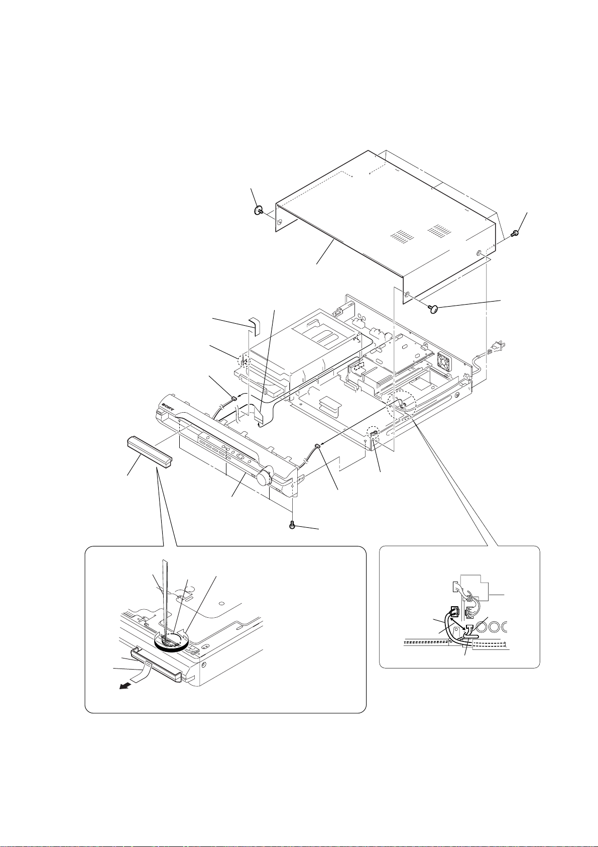
3-2. CASE, FRONT PANEL ASSY
4
two
screws
(CASE3 TP2)
9
w
ire (flat type)
23core (CN501)
8
sheet
7
case
HCD-DX375
6
five
screws
(+BVTP 3
5
two
(CASE3 TP2)
screws
×
8
3
loading panel
qa
connector (CN312)
tweezers
qd
claw
qg
front panel assy
gear
1
of bottom plate, and roate the gear in
the counter-clockwise direction.
q;
connector (CN3001)
qs
four screws (+BV3)
Insert tip of tweezers through the hole
qf
claw
When re-assembling, leave 30 mm
between harnesses A and B for safety.
harnesses A
30mm
harnesses B
DVD lid
tape
2
Attach an adhesive tape on the DVD LID and draw it out.
clamp
15
HCD-DX375
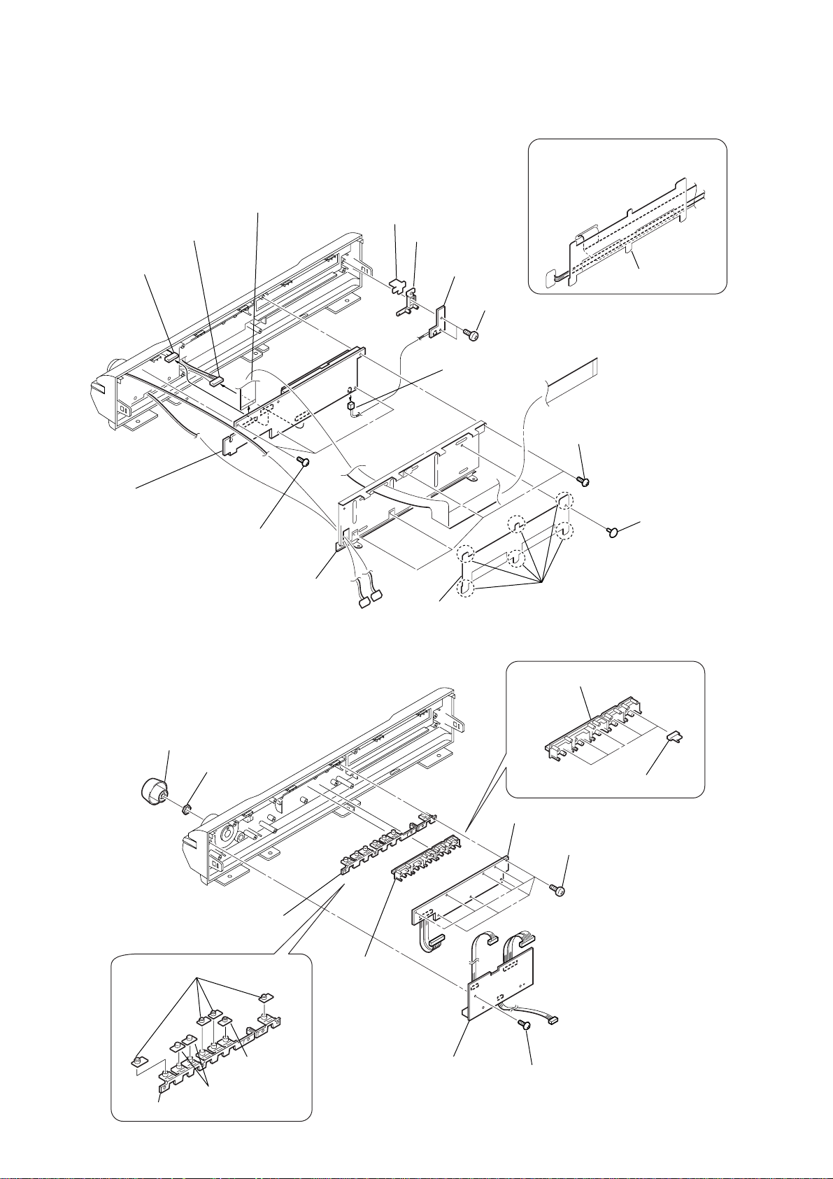
3-3. FL BOARD, SW BOARD
7
connector (CN811)
8
connector (CN805)
9
wire (flat type)
23core (CN801)
qg
cap (power)
qf
(power)
button base
qd
SW board
qs
(+BVTP 2.6)
q;
connector (CNP801)
two s
When reassembling, route the
harness and flexible cable as
shown in the illustration.
hold plate (FFC)
crews
4
four
screws (+BVTP 2.6)
qa
FL board
6
three
screws (+BVTP 2.6)
5
3-4. JACK BOARD, LED BOARD
1
knob (vol)
2
nut
shield plate (FC)
3
hold plate (FFC)
2
9
6
LED board
six
claws
button (disk)
8
5
eight
1
rivet
five indicators (disk)
screws (+BVTP 2.6)
16
qa
four
caps (FUNK)
qf
button base (PLAY)
q;
button (play)
qs
qd
two
cap (PLAY)
caps (AMS)
7
button (disk),
indicator (disk)
4
JACK board
3
screw (+BVTP 2.6)
3-5. DMB12 BOARD
3
wire (flat type) 24core (CN101)
2
connector (CN201)
4
connector (CN601)
5
wire (flat type) 5core (CN4302)
6
wire (flat type) 11core (CN4301)
7
wire (flat type) 9core (CN4501)
8
seven
screws (+BV 3)
q;
DMB12
HCD-DX375
board
1
wire (flat type) 11core (CN109)
qs
qd
two
bracket HDMI
screws (+BV 3)
9
screw
(+B 3
×
qa
two
(+BVTP 3
6)
screws
×
8)
17
HCD-DX375
)
3-6. I/O BOARD, TUNER
3
tuner
2
wire (flat type)
8
1
two screws
(+BVTT 3
7
wire (flat type) 5core(CN202)
wire (flat type)11core(CN201)
4
connector
×
6)
(CN312)
5
wire (flat type)
9core(CN203)
qa
I/O board
6
wire (flat type)
15core(CN311)
q;
Open the
back panel.
3-7. SPEAKER BOARD, D.C. FAN
9
SPEAKER board
7
two
screws
(+BV3)
1
connector
(CN3000)
9
eight screws
(+BVTP 3
3
D.C. fan
8
two
screws
(+BVTP 3
2
(+BVTT 4
two
×
8)
×
8)
screws
×
8
18
5
(CN302)
4
connector
(CN303)
6
connector
(CN301)
connector
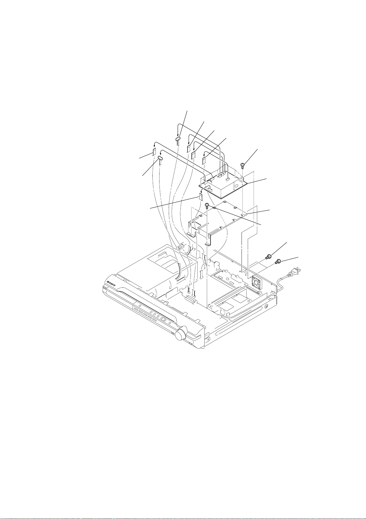
3-8. MAIN BOARD
1
wire (flat type) 23core (CN501)
qd
wire (flat type) 11core (CN504)
3
wire (flat type) 15core (CN601)
2
wire (flat type) 21core (CN622)
4
wire (flat type) 9core (CN701)
6
connector (CN303)
5
connector (CN303)
7
connector (CN302)
8
connector (CN301)
9
connector (CN3000)
HCD-DX375
After twist the harness once,
install the connector.
MAIN board
POWER board
qg
HEATSINK A board
qj
two screws
(+BVTP 3 × 10)
ql
heatsink (AMP)
wa
eight screws (+BV 3)
wd
MAIN board
qs
connector
(CN506)
qa
(CN3002)
qf
two screws (+BV 3)
connector
qh
HEATSINK B board
qk
screw
(+BVTP 3 × 12)
w;
two radiation
sheet
0
connector (CN3001)
When re-assembling, leave 30 mm
between harnesses A and B for safety.
harnesses A
30mm
clamp
When re-assembling, attaching the
two heat radiation sheets on the
IC MAIN board first, and then attach
the heat sink (AMP).
heatsink (AMP)
harnesses B
radiation
sheets
ws
IC on the
MAIN board
clamp
19
HCD-DX375
3-9. POWER BOARD
6
five screws (+PWH 3 × 8)
7
POWER board
1
connector (CN506)
4
two screws (+BV 3)
5
shield (H/L)
After twist the harness once,
install the connector.
MAIN board
POWER board
2
connector (CN3002)
3
connector (CN901)
When re-assembling, leave 30 mm between
harnesses A and B for safety.
harnesses A
30mm
clamp
harnesses B
20
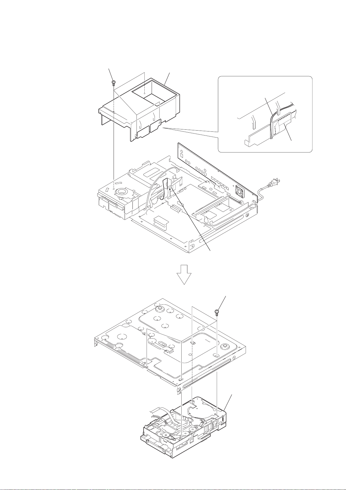
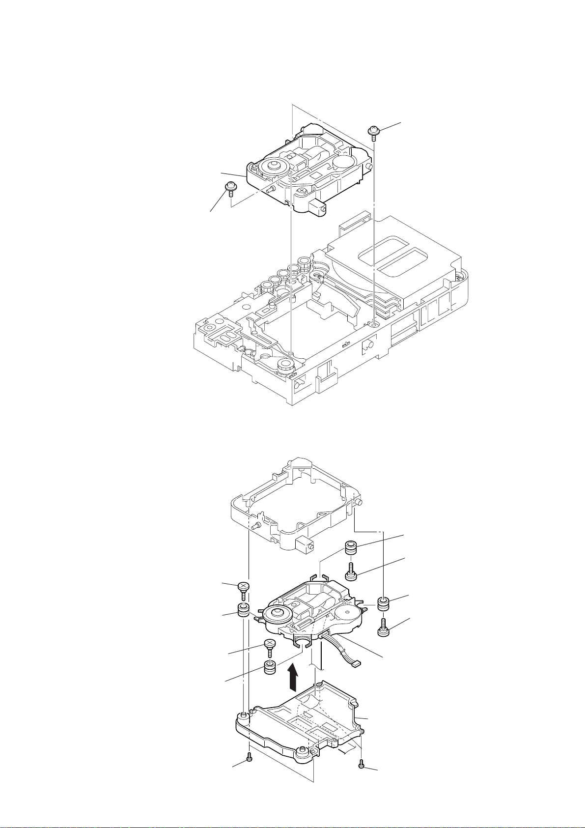
3-10. DVD MECHANISM DECK (CDM81C-D VBU101)
3
four
screws (+BV 3)
4
MD cover
HCD-DX375
2
Remove the harness and flexible cable.
harness
flexible cable
1
wire (flat type) 21core (CN622)
5
four
screws
×
(+BVTP 3
6
DVD mechanism deck
(CDM81C-DVBU101)
10)
21
HCD-DX375
3-11. TRAY
2
two screws
(+BTTP 2.6)
5
tray
4
3
bracket
1
two screws
(+BTTP 2.6)
3-12. MOTOR BOARD M761 (LD/ST MOTOR), M762 (BU U/D MOTOR)
1
screw
(+BTTP 2.6)
2
bracket
7
Remove soldering from the two points.
8
M762 (BU U/D MOTOR)
3
screw
(+BTTP 2.6)
4
MOTOR board
5
Remove soldering from the two points.
6
M761 (LD/ST MOTOR)
22
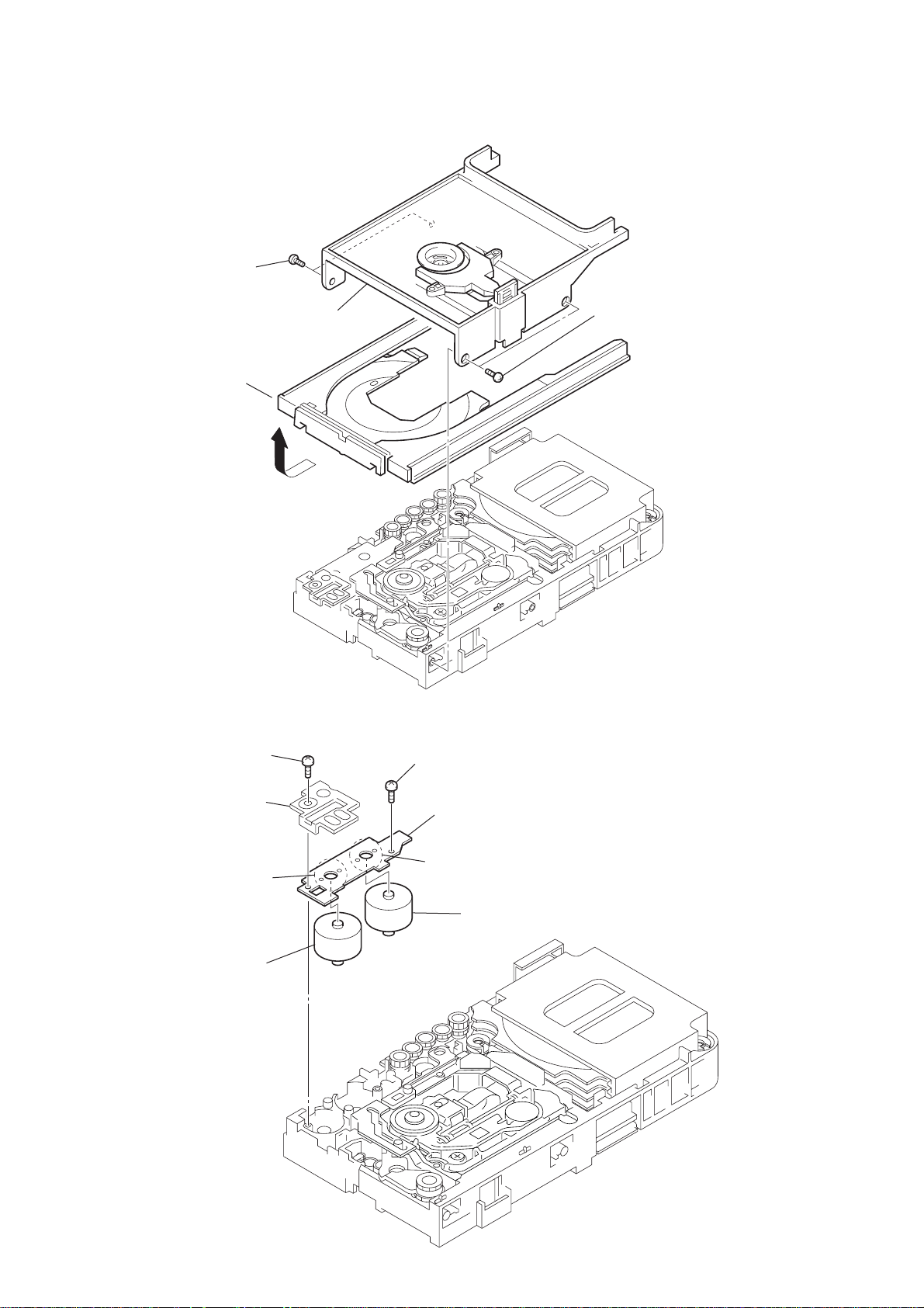
3-13. BASE UNIT (DVBU101)
w
3
base unit (DVBU101)
2
floating screw
(+PTPWH2.6)
1
two floating screws
(+PTPWH2.6)
HCD-DX375
3-14. OPTICAL PICK-UP (KHM-310CAB)
3
insulator screw
9
insulator
4
insulator screw
0
insulator
5
qa
insulator
7
insulator screw
qs
insulator
8
insulator scre
qd
optical pick-up
(KHM-310CAB)
6
holder (310) assy
2
two screws
(+BTP 2.6
×
8)
1
two screws
(+BTP 2.6
×
8)
23
HCD-DX375
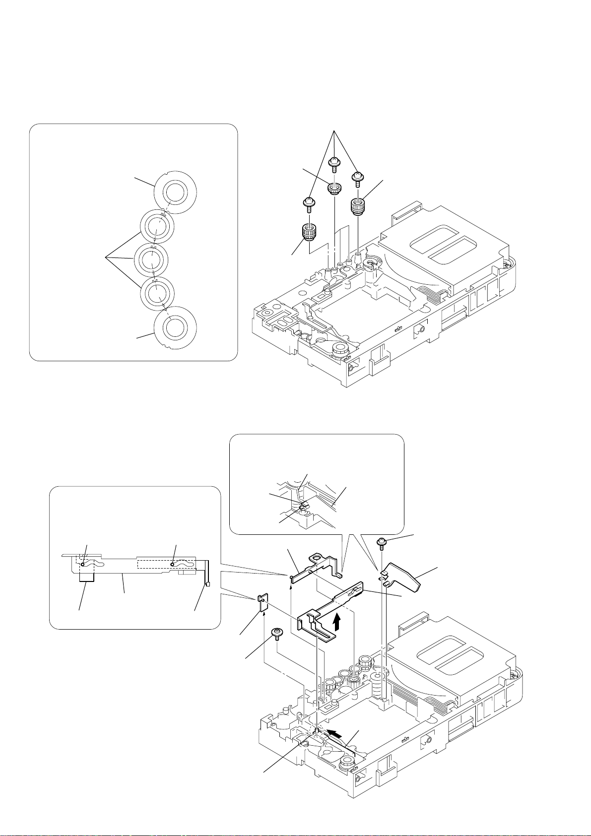
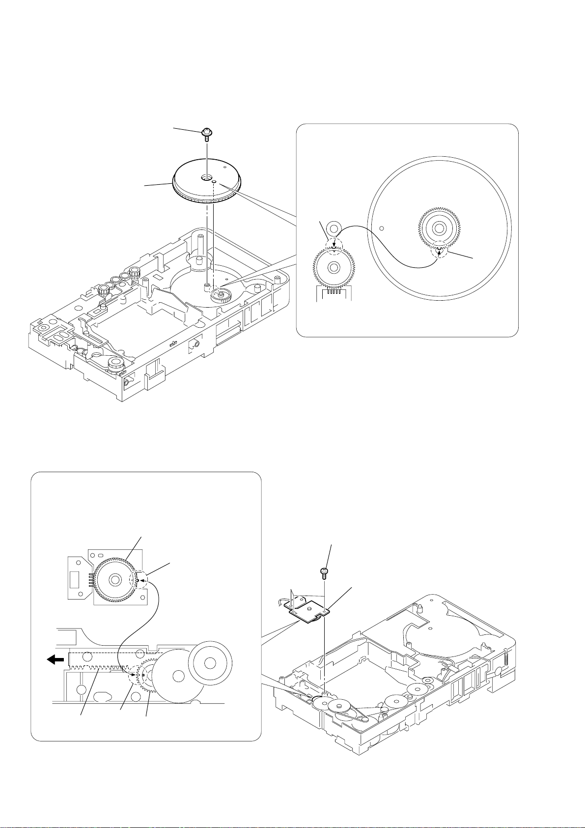
3-15. GEAR (SUB TRAY 1), GEAR (SUB TRAY 2)
PRECAUTION DURING GEAR (SUB TRAY 1/2) INSTALLATION
Align the marks of the gears as shown in the illustration.
4
(sub tray 1)
gear (sub tray 2)
gear (sub tray 1)
gear (sub tray 2)
3
1
(+PTPWH 2.6 × 8)
three gears
gear (sub tray 2)
five screws
2
gear (sub tray 2)
3-16. LEVER ASSY
Before re-assembling, align the lever (release)
and the lever (sub tray) with the lever (mode)
as shown in the illustration.
dowel dowel
lever (mode)
lever (release)
lever (sub tray)
When re-assembling, insert the lever (sub tray)
between the bosses of the shutter (tray).
boss
5
lever (sub tray)
6
lever (release)
3
floating screw
(+PTPWH M2.6)
boss
shutter (tray)
lever (sub tray)
4
1
screw
(+PTPWH 2.6 × 8)
2
shutter (tray)
7
lever (mode)
24
cam (BU)
Before re-assembling, slide the cam (BU)
in the direction of the arrow.
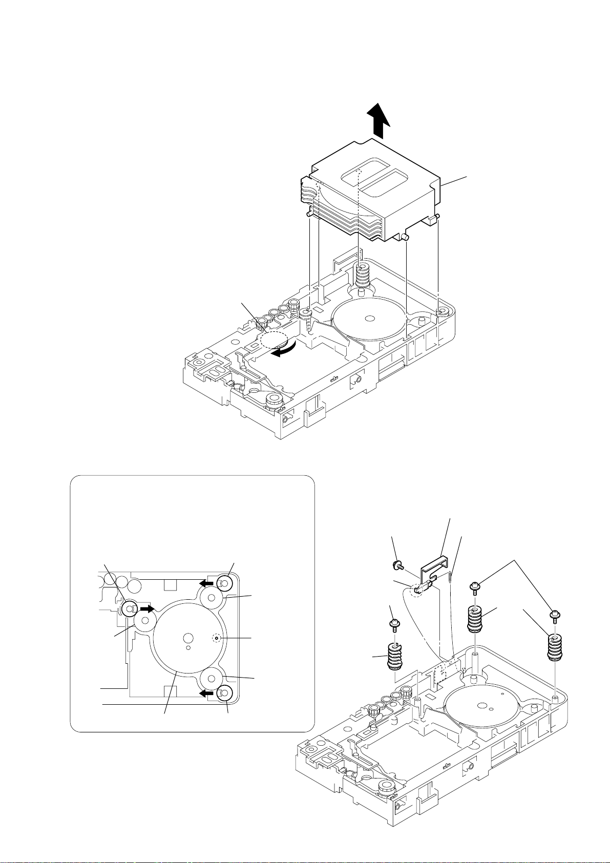
3-17. STOCKER SECTION
5
two screws
(+PTPWH 2.6 × 8)
6
two cams
(stocker)
8
cam
(stocker)
cam (stocker)
cam (stocker)
cam (stocker)
hole
gear
(stocker 2)
gear
(stocker 2)
gear
(stocker 2)
gear (stocker 3)
2
tension spring (SW)
4
lever (SW)
1
screw
(+PTPWH 2.6 × 8)
7
screw
(+PTPWH 2.6 × 8)
3
hook
PRECAUTION DURING CAM (STOCKER) INSTALLATION
Before installing the cams (stocker), fix the gear (stocker 3) in
the manner so that the hole of the gear (stocker 3) should be
aligned with the hole of the chassis located beneath
the gear (stocker 3). Be sure to install the cams (stocker) in
such a way that the grooves of the cams (stocker) face
the direction of the arrows.
1
Rotate the gear (SS3) in the
direction of the arrow.
HCD-DX375
2
stocker section
3-18. CAM (STOCKER)
25
HCD-DX375
3-19. GEAR (STOCKER 3)
1
screw
(+PTPWH 2.6
2
gear (stocker 3)
PRECAUTION DURING GEAR (STOCKER 3) INSTALLATION
×
8)
Be sure to align the rib of the gear (stocker 3) with the groove
of the rotary encoder.
groove
rib
rotary encoder
(ST U/D encoder)
gear (stocker 3)
(reverse-side)
3-20. ROTARY ENCODER (MD)
PRECAUTION DURING ROTARY ENCODER (MD) INSTALLATION
Slide the cam (BU) in the direction of the arrow so that the mark
of the gear (BU1) can be seen. Engage the gears while aligning
the mark of the gear (BU1) with the protruding part of the
rotary encoder.
rotary encoder (MD)
protruding part
cam (BU)
mark
gear (BU1)
1
three screws
(+BTTP 2.6)
2
rotary encoder (MD)
26
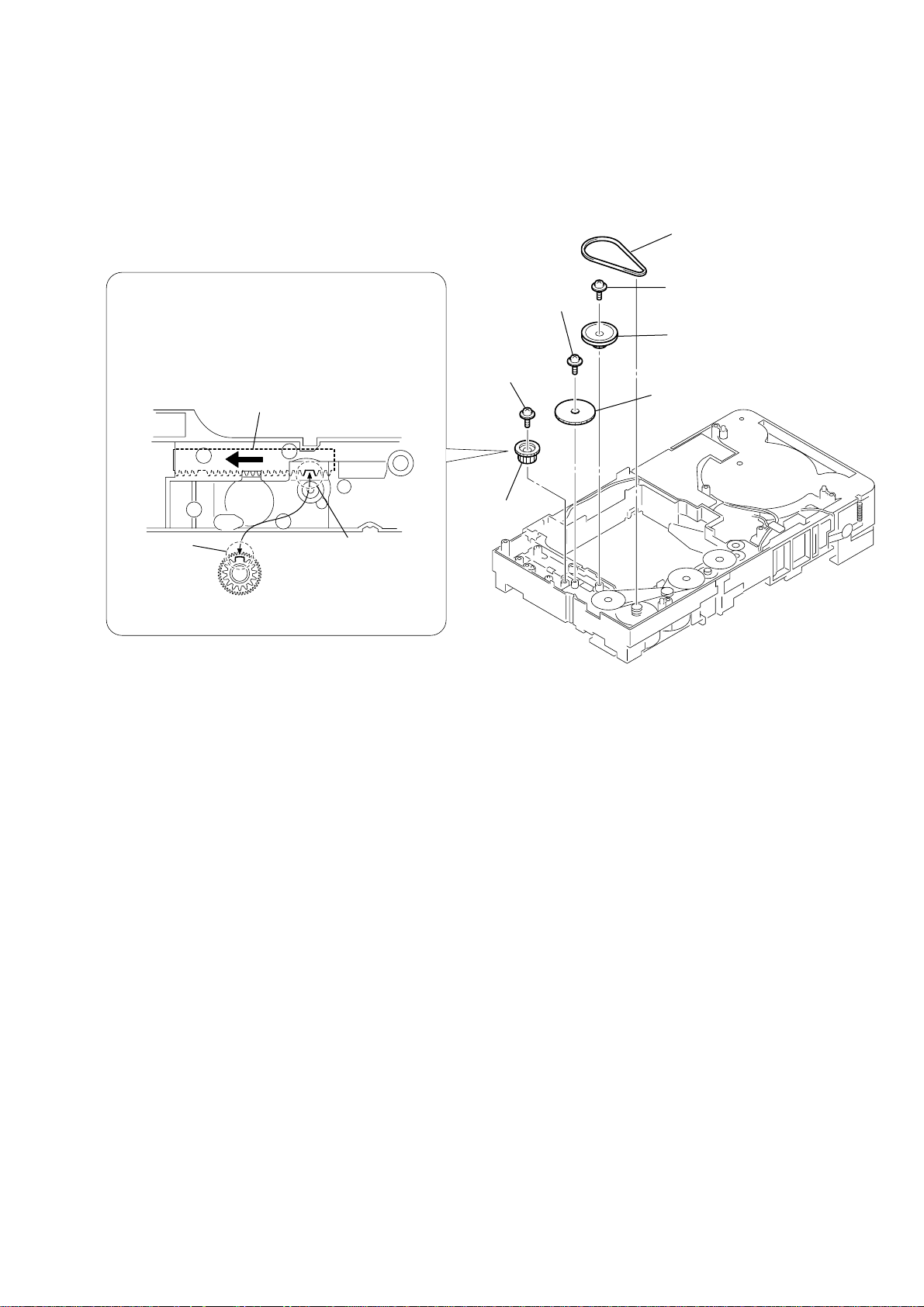
3-21. GEAR (BU1)
PRECAUTION DURING GEAR (BU1) INSTALLATION
Before re-assembling, slide the cam (BU) in the direction of
the arrow.
Assemble the gear (BU1) in such a manner that the groove
of the cam (BU) is aligned with the rib of the gear (BU1).
cam (BU)
4
screw
(+PTPWH 2.6
6
screw
(+PTPWH 2.6
HCD-DX375
1
belt (sub tray)
2
×
8)
×
8)
screw
(+PTPWH 2.6
3
pulley (BU)
5
gear (BU2)
×
8)
rib
gear (BU1)
groove
7
gear (BU1)
27
HCD-DX375
Ver. 1.1
SECTION 4
TEST MODE
Note 1: Regarding the notification symbol “R”
Because the number of the operating buttons of this product
are limited, some operations require use of the operating
buttons of the remote commander, When a specific operation
requires use of the operating buttons of the remote
commander, “R” is added to the specific operating procedure
in this manual. Example MENU/NO “R” The MENU/NO
button of remote commander.
Note 2: Incorrect operations may be performed if the test mode is
not entered properly.
In this case, press the ?/1 button to turn the po wer of f, and
retry to enter the test mode.
1. Cold Reset
• The cold reset clears all data including preset data stored in
the RAM to initial conditions. Execute this mode when
returning the set to the customers.
Procedure:
1. Press the ?/1 button to turn the power on.
2. Press three buttons x , A and ?/1 simultaneously.
3. When this button is operated, display as “COLD RESET” for
a while and all of the settings are reset.
2. Panel Test Mode
•This mode is used to check the software version, FL, LED
and KEY.
2-1. Display Test Mode
Procedure:
1. Press the ?/1 button to turn the power on.
2. Press three buttons X , . and A simultaneously.
3. When the display test mode is activated, all segments and LEDs
are turned on.
4. To exit from this mode, pr ess three buttons X , . and A
simultaneously.
2-2. V ersion T est Mode
Procedure:
1. When the panal test mode is activated, press the . button
and the message “DCX3FD” is displayed, the version test
mode is activated.
2. Whenever press the . button, the version is displayed in
order of NA, MC, SYS, UI, DVD, CDMA, CDMB, ST, TA,
DSP and TM.
3. Press the > button and the date of the softwafe production
is displayed.
4. Press the > button again and the version is displayed.
5. To exit from this mode, press three b uttons X , . and A
simultaneously.
2-3. Key Test Mode
Procedure:
1. When the panel test mode is activated, press the H button,
to select the key test mode.
2. To enter the KEY test mode, the fluorecent indicator displays
“K0 V0”. Each time a button is pressed, “KEY” value
increases. However, once a button is pressed, it is no longer
taken into account. When all keys ar e pressed correctly , “K13
V0” is displayed.
3. When the VOLUME control is turned in the direction of (+),
“V0” is changed to “V1”, then ... “V9”.
When the V OLUME control is turned in the direction of (–),
“V0” is changed to “V9”, then ... “V1”.
4. To e xit from this mode, press three buttons X , . and A
simultaneously.
3. Disc Tray Lock
The disc tray lock function for the antitheft of an demonstration
disc in the store is equipped.
Setting Procedure :
1. Press the ?/1 button to turn the set on.
2. Press the FUNCTION button to set DVD function.
3. Insert a disc.
4. Press the x button and the A button simultaneously for five
seconds.
5. The message “LOCKED” is displayed and the tray is locked.
Releasing Procedure :
1. Press the x button and the A button simultaneously for five
seconds. again.
2. The message “UNLOCKED” is displayed and the tray is
unlocked.
Note: When “LOCKED” is displayed, the slot lock is not released by
turning power on/off with the ?/1 button.
4. DVD Ship Mode
• Use this mode when returning the set to the customer after
repair.
Procedure:
1. Press the ?/1 button to turn the set on.
2. Press the FUNCTION button to set the function “DVD”.
3.
Remove all discs, press two buttons x
neously.
4. After a message “MECHA LOCK” is displayed on the
fluorescent indicator tube, pull out the AC plug.
5.
To exit from this mode, press the ?/1 button to turn the set on.
5. AM Step Change
•A step of AM channels can be changed over between 9 kHz
and 10 kHz.
Procedure:
1. Press the ?/1 button to turn the set ON.
2. Select the function “TUNER”, and press FUNCTION button
to select the BAND “AM”.
3. Press the ?/1 button to turn the set OFF.
4. Press two buttons > and ?/1 simultaneously, and the
display of fluorescent indicator tube changes to “AM 9 k
STEP” or “AM 10 k STEP”, and thus the channel step is
changed over.
6. V olume Test Mode
Procedure:
1. Press the ?/1 button to turn the power on.
2. Press three buttons . , H and > simultaneously.
3. The message “VOLUME MAX” is displayed, when the
VOLUME control is turned in the dirction of (+).
The message “VOLUME MIN” is displayed, when the
VOLUME control is turned in the dirction of (–).
4. To exit from this mode, press the ?/1 button to turn the set
off.
7. Product Out
This mode moves the optical pick-up to the position durable to
vibration and clears all data including preset data stored in the RAM
to initial conditions. Use this mode when returning the set to the
customer after repair.
Procedure:
1. Press the ?/1 button to turn the power on.
2. Press the FUNCTION button to set the function “DVD”.
3.
Remove all discs, and then
?/1 simultaneously.
4. After the “ST ANDBY” blinking display finishes, the message
“MECHA LOCK” is displayed on the fluorescent indicator
tube disconnect the A C po wer plug, then the ship mode is set.
press three buttons > , A and
,
and . simulta-
28

HCD-DX375
Ver. 1.1
DVD SECTION
[TEST DISC LIST]
Be sure to use the DVD disc that matches the signal standards of
your region.
• CD YEDS-18 (Part No.: 3-702-101-01)
PATD-012 (Part No.: 4-225-203-01)
• DVD SL (Single Layer)
NTSC : HLX-503 (Part No.: J-6090-069-A)
HLX-504 (Part No.: J-6090-088-A)
PAL : HLX-506 (Part No.: J-6090-077-A)
• DVD DL (Dual Layer)
NTSC : HLX-501 (Part No.: J-6090-071-A)
HLX-505 (Part No.: J-6090-089-A)
PAL : HLX-507 (Part No.: J-6090-078-A)
8-1. GENERAL DESCRIPTION
The Mirror Time and IOP measurement allows you to make
diagnosis and adjustment simply by using the remote commander
and monitor TV. The instructions, diagnosis results, etc. are given
on the on-screen display (OSD).
Be sure to execute the Mirror Time and IOP measurement when a
BU (Base Unit) is replaced.
8-2. HOW TO ENTER TEST MODE
While pressing the
VOLUME + with the DVD player in power on.
The T est Mode starts, then the menu shown belo w will be displayed
on the TV screen.
0. External Chip Check
1. Servo Parameter Check
2. Drive Manual Operation
3. Emergency History Check
4. Version Information
Model Name : DCX3FD_UC
IF-con : V
Syscon : Ver.
The menu above is the Remocon Diagnosis Menu screen which
consists of six main function. At the bottom of the menu screen, the
model name and IF-con version. To enter Mirror Time
Adjustment menu, press button 2 “R” on the remote commander
to enter Drive Manual Operation menu. To exit from the T est Mode,
press the power button on the remote commander.
x and A buttons simultaneously, turn
Remocon Diagnosis Menu
er. XX.XX (XXXX)
X.XXX
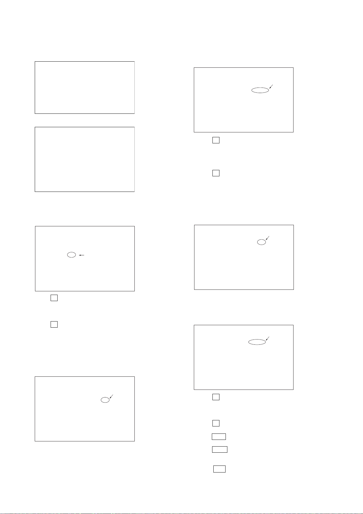
8-4. MIRROR TIME ADJUSTMENT
To enter Mirror Time Adjustment, press 5 “R” button on the remote
commander. The screen will appear as below.
MIRR time Adjust Menu
1. CD MIRR time Check:
2. DVD MIRR time Check:
3. Threshold:
4. Save to EEPROM:
5. Default set MIRR time:
[Open] Tray open [Close] Tray close
[0] Return to previous menu
There are five main commands in the Mirr time Adjust menu as
shown in the figure above. The functions of each command are
described in the following page.
1. CD MIRR time Check
This command checks the Mirror time value for CD disc.
2. DVD MIRR time Check
This command checks the Mirror time value for DVD disc.
3. Threshold
This command displays the threshold value between CD and DVD
mirror time.
4. Save to EEPROM
This command saves an adjusted mirror time value to the EEPR OM.
5. Default set MIRR time
This command will set CD and DVD mirror time to firmware def ault
value.
[Open] / [Close]
Pressing the A button controls the tray for disc change during
mirror time adjustment.
[0] Return to previous menu
Press the 0 “R” button to return to previous menu.
8-4-1. EXECUTING MIRROR TIME ADJUSTMENT
In order to execute mirror time adjustment, the following standard
procedures must be followed.
(1) In power on, while pressing the x and A buttons
simultaneously, turn VOLUME + .
(2) Select “2. Drive Manual Operation”.
8-3. DRIVE MANUAL OPERATION
The Drive Manual Operation menu consists of five main function.
By pressing 2 “R” button on the remote commander in the Remocon
Diagnosis Menu, the screen will appear as below.
Drive Manual Operation
1. Servo Control
2. Track/Layer Jump
3. Manual Adjustment
4. Tray Aging Mode
5. MIRR time Adjust
0. Return to Top Menu
Remocon Diagnosis Menu
0. External Chip Check
1. Servo Parameter Check
2. Drive Manual Operation
3. Emergency History Check
4. Version information
Model Name : DCX3FD_UC
IF-con : Ver. XX.XX (XXXX)
Syscon : Ver. X.XXX
29
HCD-DX375
(3) Select “5. MIRR time Adjust”.
Drive Manual Operation
1. Servo Control
2. Track/Layer Jump
3. Manual Adjustment
4. Mecha test mode
5. MIRR time Adjust
0. Return to Top Menu
(4) Select “5. Default set MIRR time”.
MIRR time Adjust Menu
1. CD MIRR time Check:
2. DVD MIRR time Check:
3. Threshold:
4. Save to EEPROM:
5. Default set MIRR time:
[Open] Tray open [Close] Tray close
[0] Return to previous menu
(5) Select “3. Threshold”.
(6) Confirm the number. If it is 7D, go to next step. If it is any
other value, return to step 4.
MIRR time Adjust Menu
(14) Confirm the same values are displayed. If it is not same,
return to step 7.
MIRR time Adjust Menu
1. CD MIRR time Check:
2. DVD MIRR time Check: XX XX
3. Threshold:
4. Save to EEPROM:
5. Default set MIRR time:
[Open] Tray open [close] Tray close
[0] Return to previous menu
(15) Push the A button to eject tray.
(16) Take out HLX-504 and insert Test Disc YEDS-18 into
tray.
(17) Push the A button to close tray.
(18) Push “1. CD MIRR time check”.
(19) Wait for HEX number to display.
(20) Confirm the number, if YY is 5A – E8, proceed with next
step. If no, return to 15.
MIRR time Adjust Menu
1. CD MIRR time Check:
2. DVD MIRR time Check:
3. Threshold: 7D
4. Save to EEPROM:
5. Default set MIRR time:
[Open] Tray open [Close] Tray close
[0] Return to previous menu
(7) Push the A button to eject tray.
(8) Insert Test Disc HLX-504 into tray.
(9) Push the A button to close tray.
(10) Push “2. DVD MIRR time Check”.
(11) Wait for HEX number to display.
(12) Confirm the number, if XX is 28 – 70, proceed with next
step. If no, return to 8.
MIRR time Adjust Menu
1. CD MIRR time Check:
2. DVD MIRR time Check: xx xx
3. Thereshold:
4. Save to EEPROM:
5. Default set MIRR time:
[Open] tray open [close] Tray close
[0] Return to previous menu
1. CD MIRR time Check: yy YY
2. DVD MIRR time Check: XX XX
3. Threshold:
4. Save to EEPROM:
5. Default set MIRR time:
[Open] Tray open [close] Tray close
[0] Return to previous menu
(21) Push “4. Save to EEPROM”.
(22) Confirm the same values are displayed. If it is not the
same, return to step 15.
MIRR time Adjust Menu
1. CD MIRR time check: YY YY
2. DVD MIRR time check: XX XX
3. Threshold:
4. Save to EEPROM:
5. Default set MIRR time:
[Open] Tray open [close] Tray close
[0] Return to previous menu
(23) Push the A button to eject tray.
(24) Remove Test Disc YEDS-18 from tray.
(25) Push the A button to close tray.
(26) Press the 0 “R” button to the Drive Manual Operation menu.
(13) Push “4. Save to EEPROM”.
30
(27) Press the 0 “R” button to return to the Remocon Diagnosis
Menu.
(28) Press the ?/1 button to switch OFF set.
 Loading...