

Page 1
SONY*
Video TV Recorder
GV-500
Operating Instructions
Before operating the unit, please read this manual thoroughly
and retain it for future reference.
3-753-850-21 (2)
WALKMAN
© 1991 by Sony Corporation
Page 2
To prevent fire or shock hazard, do not expose the unit to rain or moisture.
CAUTION
ftlSK OF ELECTRIC SHOCK
W
00 NOT OPEN
1
CAUTION. TO REDUCE THE RISK OF ELECTRIC SHOCK.
DO HOT REMOVE COVER (OR BACK).
NO USER^ERVICEABLE PARTS INSIDE.
REFER SERVICING TO QUAUFIED SERVICE PERSONNEL
This symbol is intended to alert the user to the presence of uninsulated
‘dangerous voltage’ within the product's enclosure that may be of sufficient
magnitude to constitute a risk of electric shock to persons.
This symbol is intended to alert the user to the presence of important
operating and maintenance (servicing) instructions in the literature
accompanying the appliance.
Owner’s Record
The model and serial numbers are located on the bottom. Record the serial number in the
space provided below. Refer to these numbers whenever you call upon your Sony dealer
regarding this product.
Model No. GV-SOO
Serial No..
Page 3

INFORMATION
This equipment generates and uses radio frequency energy and if not instailed and used
properly, that is, in strict accordance with the manufacturer’s instructions, may cause
interference to radio and television reception, it has been type tested and found to comply with
the limits for a Class B computing device in accordance with the specifications in Subpart J of
Part 15 of FCC Rules, which are designed to provide reasonable protection against such
interference in a residential installation. However, there is no guarantee that interference will not
occur in a particular installation. If this equipment does cause interference to radio or television
reception, which can be determined by turning the equipment off and on, the user is encouraged
to try to correct the interference by one or more of the following measures:
Reorient the receiving antenna
Relocate the equipment with respect to the receiver
Move the equipment away from the receiver
Plug the equipment into a different outlet so that equipment and receiver are on different
branch circuits.
If necessary, the user should consult the dealer or an experienced radio/television technicictn for
additional suggestions. The user may find the following booklet prepared by the Federal
Communications Commission helpful:
“How to Identify and Resolve Radio-TV Interference Problems”. This booklet is available from
the U.S. Government Printing Office, Washington, DC 20402, Stock No. 004-000-00345-4.
Note to CATV system installer:
This reminder is provided to call the CATV system installer’s attention to Article 820-40 of the
NEC that provides guidelines for proper grounding and, in particular, specified that the cable
ground shall be connected to the grouncfing system of the building, as close to the point of cable
entry as practical.
Television programs, films, video tapes and other materials may be copyrighted. Unauthorized
recording of such material may be contrary to the provisions of the copyright laws.
PCM recording/playback is not possible with this unit. The PCM sound recorded with another
recorder cannot be played back with this unit.
For using this unit abroad, see page 76.
Page 4
raamiiHiEBiij
1
Preliminary
Connecting other
equipment
Features..................................................................................................... 5
Location of parts and controls
Power sources'.........................................................................................11
Setting the date and dock...........................................................................18
Presetting TV channels..............................................................................22
Watching TV programs.............................................................................. 26
Listening to stereo programs or SAP broadcast..........................................30
Adjusting the picture and sound................................................................ 31
Using the SLEEP timer
Inserting a cassette....................................................................................34
Recording TV programs
Recording stereo programs or SAP broadcast............................................40
Timer-activated recording.......................................................................... 41
Playing back the recorded tapes
Playing back the desired portion repeatedly—A-B repeat
function...............................................................................................50
Using indexes-to find the desired scene quickly
Settings in the VTR MODE SET menu.........................................................57
Connecting an outdoor antenna and CATV cable........................................60
Connecting other VCRs or monitors.......................................................... 61
Editing tapes............................................................................................. 69
Precautions
Maintenance............................................................................................. 74
Notes on moisture condensation
Using your video TV recorder abroad......................................................... 76
Specifications........................................................................................... 77
List of recommended accessories
Troubleshooting........................................................................................80
List of on-screen displays.......................................................................... 82
Quick reference for timer recording
..............................................................................................
.....................................................................
..............................................................................
............................................................................
................................................................
.........................................
...............................................................
.............................................................
............................................................
7
33
36
47
51
73
75
79
83
Page 5

Preliminary
The “Video Walkman* GV-SOO is an 8 mm video recorder with an LCD (Liquid Crystal Display).
Its compact and lightweight design allows you to watch TV programs and video tapes anywhere
and anytime you like.
With this video TV recorder, you can:
- view the playback picture of 8 mm video tapes.
- view TV programs.
- record TV programs.
In addition, by connecting it to a video camera (not supplied), you can record pictures with the
camera, and play back the recorded pictures on it immediately.
0№er FM^res
- Menu function for setting six items
- Hi-fi stereo for high quality sound*
- Stereo TV tuner for enjoying stereo programs or SAP (Second Audio Program) broadcast**
- Index function for finding the desired scenes quickly
- A-B repeat function for playing back the desired portion repeatedly
- CRYSTAL-CLEAR still/slow/picture search on LCD
- Timer-activated recording
- SLEEP timer for turning off the unit automatically
- MEGA BASS circuit for dynamic bass sound
- SURR (surround) function for enjoying wide soundscape
- Playback of tapes recorded in Hi8 video system
fim-fi Stetig SysteiiT
On the 8 mm video standard track, the sound is recorded/played back in Hi-fi monaural. The
PCM digital stereo sound is recorded/played back on the PCM track as an option.
With this unit. Hi-fi stereo sound can be recorded on the standard track.
To maintain compatibility with the conventional Hi-fi monaural equipment, the Hi-fi stereo sound
is recorded as L-R sound using the 1.7 MHz carrier and L+R sound using the 1.5 MHz carrier as
the FM audio signal.
To playback the tape recorded by its hi-fi stereo system, this unit uses a matrix circuit to
produce the L and R stereo sounds separately. When conventional Hi-fi monaural equipment is
used to play back a tape recorded in Hi-fi stereo, it will produce the L+R monaural sound
because it can reproduce only the 1.5 MHz carrier.
The Hi-fi stereo system of this unit provides a live stereo sound atmosphere even when using
the 8 mm video standard track.
This unit uses 8 mm video format cassettes. It records in the SP mode (approximately 1.43 cm/
second) and the LP mode (Approximately 0.72 cm/second) and can play back in the SP mode
and LP mode. The quality of the playback picture in the LP mode, however, will not be as good
as that in the SP mode.
Page 6

**SAP (Second Audio Program) Broadcast
This unit can receive SAP broadcasts automatically when AUTO SAP is set to ON in the VTR
MODE SET menu. When an SAP broadcast is received, sound is recorded using the 1.5 MHz
carrier.
When an SAP broadcast is not received, main scund is recorded.
When AUTO SAP is set to OFF in the VTR MODE SET menu, main sound is recorded on the
normal track.
Menu Display Function
The GV-500 is equipped with a menu display function. Menu display enables you to perform
certain operations which are displayed on the screen.
First open the front cover and push MENU.
A MENU display showing six setting items will appear on the screen. Select the desired item so
that the screen changes to the desired setting display. Then operate for the setting, watching
the display on the screen.
MENU Display
Menu item
TIMER SET
SLEEP TIMER
Setting purpose
To preset a timer-activated recording
To turn off the unit automatically after a certain
time
Reference
page
41
33
VTR MODE SET
TV ADJUST
CLOCK SET
TUNER PRESET
• To select to receive SAP broadcast (AUTO SAP
ON/OFF)
• To select to receive TV programs in stereo or
monaural (AUTO STEREO ONADFF)
• To set the unit in the edit mode (EDIT ON/OFF)
• To adjust the tracking for the still picture or slow
motion playback picture (SLOW TRACKING)
• To adjust color intensity (COLOR)
• To adjust tones (HUE)
• To adjust color and tones to the standard levels
(STANDARD)
To set date and clock
To preset TV channels
57
31
18
22
Page 7
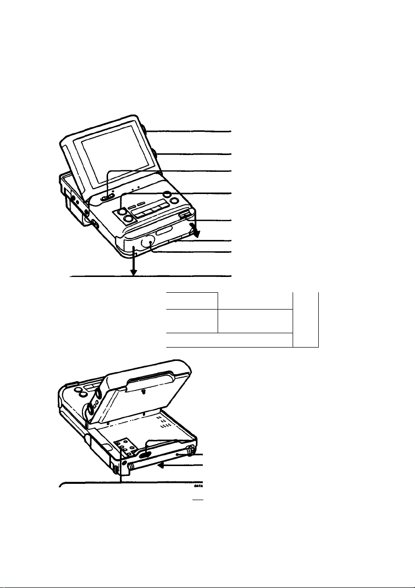
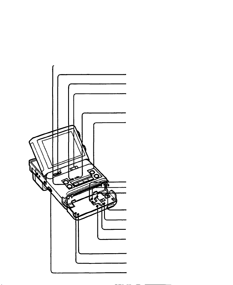
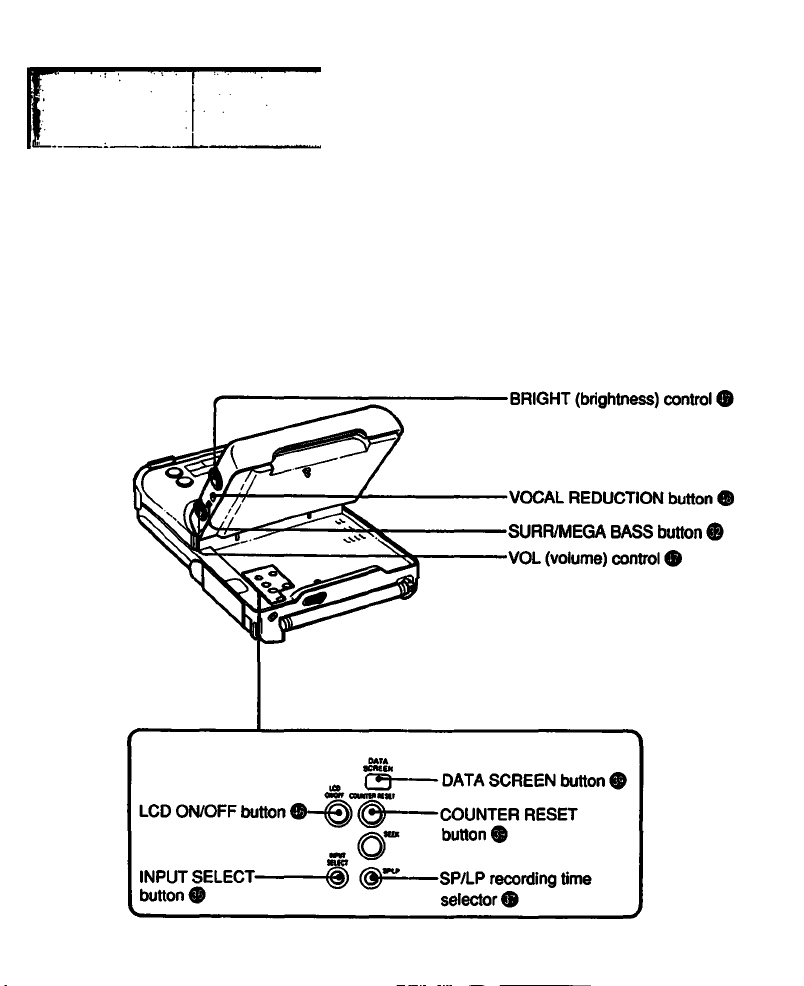
For details, refer to the pages indicated in •.
Parts used for watching TV programs
BRIGHT (brightness) control ®
VOL (volume) control 9
POWER switch 9 9
CHANNEiyiNDEX +/- buttons 9
PUSH OPEN ▼ button 9 9
Lithium battery compartment 9
Speaker
I
LCD ON/OFF button 9
INPUT SELECT button
I
-----------
.-S
1 та
CB---------DATA SCREEN button 9
®o
^------------^SEEK button 9
Cursor direction
buttons
ENTER button
—MENU button J
-ВАТТ (battery eject) knob
■Telescopic antenna
Battery mounting surface
99
9
Page 8
Parts used for VCR playback/recording
CHANNEL/INDEX +/- buttons ® ®
POWER switch
INDEX button
Indication lamps
TIMER REC (recording) lamp ® ®
REC (recording) lamp ®
A-B REPEAT button ®
Tape transport buttons ® ®
!»■ SLOW button
II PAUSE button
◄◄ @ REW (rewind) button
© ►► FF (fast-forward) button
> PLAY button
□ STOP button
TIMER CLEAR button®
TIMER CHECK button®
TIMER REC (recording)
ON/OFF button!
± EJECT button ®
ENTER button
Cursor direction buttons
MENU button
INDEX ERASE button®
INDEX MARK button ®
REC (recording) switch ®
® ® ®
Page 9
Page 10
Parts used for connection
-RFU DC OUT jack®
-VIDEO AUDIO INA)UT jacks ® ®
CAMERA connector ® ® ®
Page 11
Getting Ready
Place
Indoors AC power adaptor
AC-V30
Outdoors
In the car
Battery pack
NP-66H (supplied)
NP-77HD, NP-77H or NP-77
DC pack DCP-77 or Car battery charger/adaptor DC-V30
Power sources
Page
16
NP-55
12
The above accessories, except for the AC-V30 and NP-66H, are not supplied.
Disconnecting the power source during recording or playback operations may damage the
inserted cassette tape. If this should happen, supply power again immediately and turn the
power on.
17
Page 12
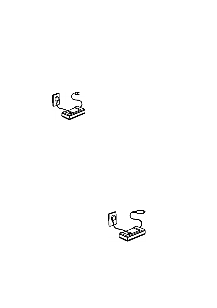
Using with Battery Pack—NP-66H, NP-77HD, NP-77H, NP-77 or NP-55
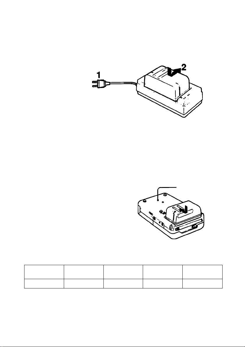
Rrst, charge the battery pack.
Use the supplied AC-V30 AC power adaptor.
1 Plug the AC-V30 into a wall outlet.
2 Install the battery pack.
Align the flat side of the battery pack
with the line on the AC power adaptor.
Then push down and slide the battery
pack in the direction of the arrow.
The Power lamp (green) and the CHARGE lamp (orange) on the AC-V30 will light. The
charging will begin.
When the charging is completed, the CHARGE lamp goes out. Unplug the AC power
adaptor and the POWER lamp will go out.
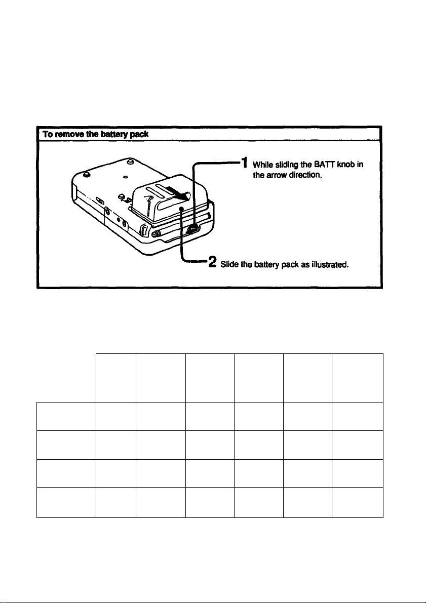
2 Attach the battery pack to the video TV recorder.
Align the right side of the battery pack
with the white line on the video TV
recorder, and while pressing the battery
pack, slide it as illustrated.
Bottom
Required charging time
NP-66H
(supplied)
100 min. 140 min.
(Approx, minutes using AC-V30)
• The battery pack cannot be charged when the AC power adaptor is used to operate the unit.
• An NP-66H, NP-77HD, NP-77H, NP-77 or an NP-55 can also be charged with the BC-S10,
BC-55 or BC-77 battery charger.
NP-77HD
NP-77H NP-77 NP-55
140 min. 120 min. 60 min.
12
Page 13
f ]0(«rMng time
A fully-charged battery pack lasts for:
LCD
OH/OFF
Watching TV
programs
VCR playing
back
TV program
recording
Camera
recording*
* Approx, minutes, when connecting the color video camera CCD-G1 (not supplied).
ON
ON
ON
OFF
NP-66H
Approx.
1()5 min.
Approx.
90 min.
Approx.
80 min.
Approx.
75 min.
NP-77HD NP-77H
Approx.
140 min.
Approx.
120 min.
Approx.
110 min.
Approx.
100 min.
Approx.
140 min.
Approx.
120 min.
Approx.
110 min.
Approx.
100 min.
NP-77 NP-55
Approx.
115 min.
Approx.
100 min.
Approx.
90 min.
Approx.
80 min.
Approx.
60 min.
Approx.
50 min.
Approx.
45 min.
Approx.
40 min.
Page 14
Using the Battery Pack Efficiently
A'q^ng the rechargeable battery paci»
__________
__
Have sufficient battery pack power to perform 2 or 3 times the
amount of viewing that you pian to do.
‘Battery life* as indicated in the instruction manual or catalogue of the
video TV recorder is measured by the continuous use of the video TV
recorder, at room temperature, using a fully charged battery.
Fast winding or rewinding tape operations consumes much more
battery power than normal tape transport operation. Consequently,
battery life becomes shorter when these operations are performed
frequently.
Battery life is shorter in a cold climate.
Cold climates reduce the efficiency of a battery and cause it to run
out more quickly.
pVHèn to replace the rechargeable battery pack
When the battery pack is exhausted, the POWER lamp starts blinking
slowly. During recording, the ‘BATTERY DOWN* indication also
starts blinking.
Replace the battery when the blinking changes from slow to fast, and
the ‘BATTERY DOWN* indication lights (the indication remains lit for
five seconds before the power goes off).
Turn off the power of the video TV recorder before replacing the
battery. While replacing the battery, keep the cassette Inside the
cassette holder. When the battery has been replaced, viewing can be
resumed smoothly without any picture distortion.
____
Notes on battery exhaustion when a camera is connected
When the battery is exhausted, the tally lamp (red) displayed in the
viewfinder of the camera starts blinking, and the power goes off
automatically. Replace the battery pack with a fully charged one
when the blinking starts.
Notes on charging
Before using the battery pack, charge it sufficiently. A brand-new battery pack is not charged.
Recharge the battery pack when it is fully exhausted.
• If the operation is completed before the BATTERY DOWN indication on the screen or POWER
lamp starts blinking, it is recommended that you discharge the battery pack by playing back a
tape until the BATTERY DOWN indication lights or the POWER lamp starts blinking rapidly.
• Do not recharge the battery pack before it has been discharged completely. Repeated
charging while some capacify remains will reduce the battery capacity. However, the original
battery capacity can be recovered if you fully discharge and fully charge the battery pack
again.
Id
Page 15

1 Keep the terminals clean
If the terminals (metal parts on the back) are soiled, the battery life will become shorter. When
the terminals are soiled, or when the battery pack has not been used for a long time, repeatedly
attach and remove it several times. This will improve the contact of the battery pack and the
video TV recorder. Also, wipe the + and - terminals with a soft cloth or paper.
on rechargeable battery pack
Battery pack care
• Remove the battery pack from the video TV recorder after use, and keep it in a cool place.
When the battery pack is installed on a video TV recorder, a small amount of current flows to
the recorder even if the POWER switch is turned off. This causes overdischarge and,
consequently, shortens the life of the battery.
• The battery pack is always discharging even when it is not in use. Thus, the battery should be
charged before each use.
How to use the switch on the battery pack
Use this switch as a reminder of the charging condition. Set the
switch to the ‘no mark” position when the charging is completed.
Set the switch to the ‘red mark” position when the battery has
been discharged.
How many times can the battery pack be recharged?
It can be fully charged and discharged about 500 times under normal temperatures. If the
BATTERY DOWN indication blinks rapidly just after turning on the recorder, even though a fully
charged battery pack has been installed, replace the battery pack with a brand new one.
Switch
Charging temperature
Lower temperature require a longer charging time.
Charging under a temperature ranging from 10‘C to 30°C (50°F to 86°F) is recommended.
Why the battery pack heats up?
While the battery pack is being charged or used, a chemical change occurs inside the battery
pack which generates electric energy. Consequently, the battery pack becomes warm, but this
is not dangerous.
Carrying the battery pack
If the + and - temiinals are short-circuited with a piece of metal, the battery heat up abnomially.
This is very dangerous. Never put an uncovered battery pack in a pocket together with a key
holder or other metal object.
If the battery pack Is not used for a long time (about 1 year)
Charge it again, but in this case the battery life will be shorter than normal. After several
charging and discharging cycles, the battery life will recover its original capacity.
Page 16
i ¿/Г1-;7а»«ппг«гд1
Using House Current
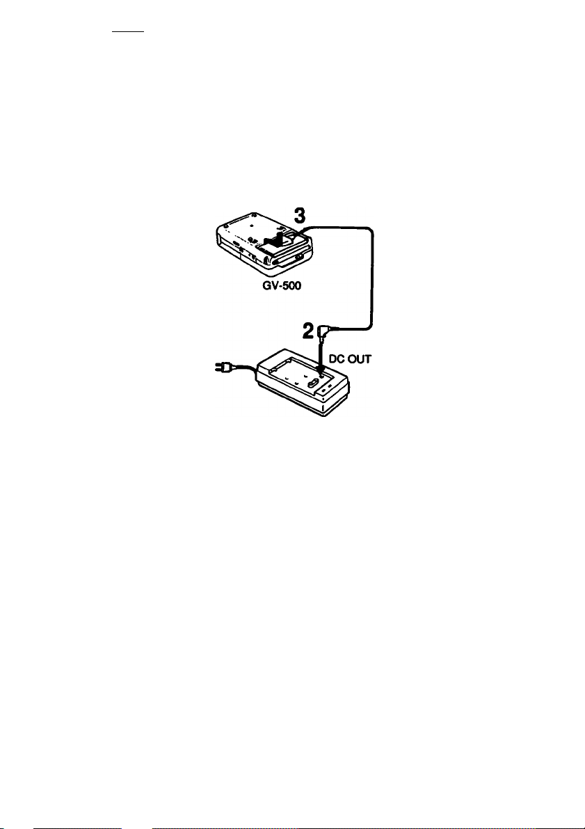
Use the supplied AC-V30 AC power adaptor.
1 Connect the AC power adaptor to a wall outlet.
2 Insert the connecting cord supplied with the AC-V30 AC power
adaptor into the DC OUT jack on the AC power adaptor.
3 Align the right side of the connecting plate with the white line on the
video TV recorder, and while pressing it, slide it in the direction of the
► mark.
1
AC-V30
To remove the connecting plate
While sliding the ВАТТ knob, slide out the connecting plate.
CAUTION
TO PREVENT ELECTRIC SHOCK, DO NOT USE THIS POLARIZED AC PLUG WITH AN
EXTENSION CORD, RECEPTACLE OR OTHER OUTLET UNLESS THE BLADES CAN BE
FULLY INSERTED TO PREVENT BLADE EXPOSURE.
• The unit is not disconnected from the AC power source as long as it is connected to the wall
outlet.
• One blade of the plug is wider than the other for the purpose of safety and will fit into the wall
outlet only one way. If you are unable to insert the plug fully into the outlet, contact your
dealer.
• While the unit is in use, particularly during charging, keep it away from AM receivers and video
equipment because it will disturb AM reception and video operation.
•
16
Page 17
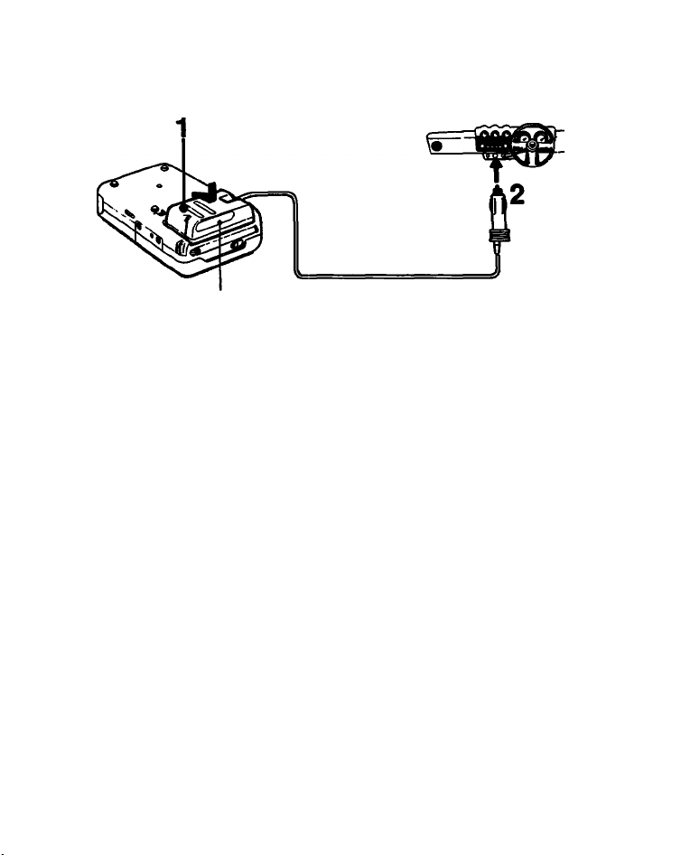
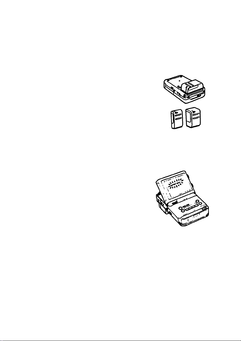
Using a Car Battery
12V or 24V car battery
DCP-77
(not supplied)
1 Attach the DC pack to the video TV recorder.
2 Connect the plug to the cigarette lighter socket
• Connect the DCP-77 only to a car with a negative ground car batteries of 12 V or 24 V.
• Attach or remove the DC pack in the same way as the battery pack.
• DCP-S5 is not recommended for this unit because the capacity of the DCP-5S is not enough to
operate it.
Notes
• Be careful not to let any metal object touch the metal projection on the battery pack. When the
battery pack is not used, keep it in its case.
• Keep the video TV recorder away from the power source. If not, noise may appear on the
screen.
•7
Notes on using this unit in a car
• For your safety, do not watch the TV or operate the controls while driving.
• Avoid leaving the unit in a place with very high temperatures. If you do, it may cause
distortion of the cabinet or malfunction of the unit.
• If you use this unit while your car is not in use, the car battery will be consumed. Avoid
using this unit in such condition for more than 12 hours.
• Remove the car battery cord from the cigarette lighter socket if you do not use the unit
for a long time.
Page 18
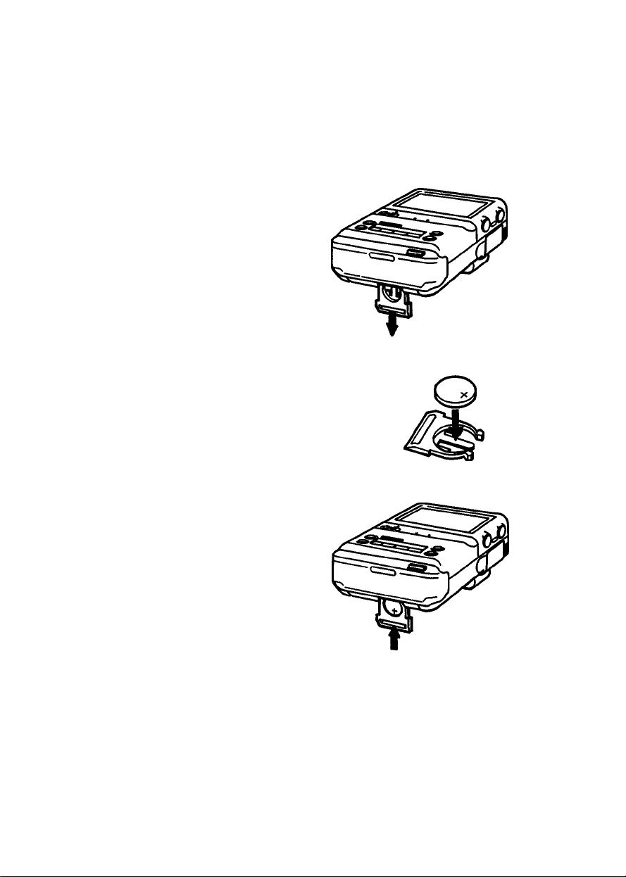
Before you set the clock, install a lithium battery. With a lithium battery installed, this unit powers
the clock and keeps the last channel in memory when the power source is disconnected.
Inserting a Lithium Battery
1 Pull out the lithium battery holder.
Pull Down
2 Insert the supplied CR2032 lithium battery with
the (plus) side facing out.
• Wipe the battery with a dry cloth to assure good
contact.
• Be sure to install the battery with the correct polarity,
otherwise the battery will not be connected.
3 Put the lithium battery holder back into the
video TV recorder.
Be sure to install to the point where it cannot be
pushed further.
18
Page 19

battery jite
The battery lasts for approximately 1 year in normal operation.
When the lithium battery becomes weak, the — indication appears on the screen when the
DATA SCREEN button is pressed, In this case, replace the battery with a Sony CR2032 lithium
battery. Use of any other battery may present a risk of fire or explosion.
After replacing the battery, reset the clock.
Notes on lithium battery
• Keep the lithium battery out of the reach of children.
Should the battery be swallowed, consult a doctor immediately.
• Before use, wipe the battery with a dry cloth to assure a good contact.
• Do not hold the battery with metalic tweezers, otherwise a short-circuit may occur.
• Do not break up the battery or throw it into a fire because it may explode. Carefully
dispose of the used batteries.
Page 20
Before setting
• Make sure that the power source and the lithium battery are installed correctly.
• The internal clock of this video TV recorder operates on a 12-hour cycle.
AMI 2:00 stands for midnight.
PM12:00 stands for noon.
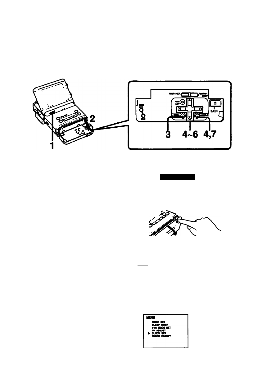
Setting the Date and Clock
Example: To set the date/clock to PM 1:15, July 4.1992.
1 Turn the power on.
The power lamp lights.
While pressing the green button, slide
the POWER switch to the right.
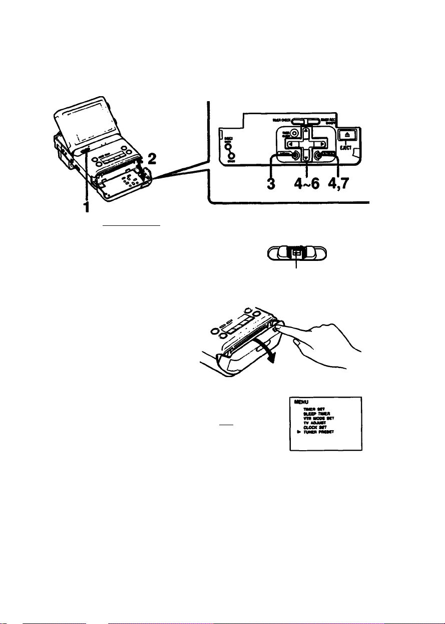
2 Open the front cover.
POWER «Or
nJ..''
mtDWfOFF
3 Press MENU.
The MENU display will appear.
4 Press Q / Q until ^ points to
CLOCK SET, then press ENTER.
The CLOCK SET setting display will
appear.
20
•-|—Upwards
0-'
I MENU
Downwards
MENU
tWKfl «T
tu» TMtII
VTH Moot MT
TV AOMtt
aocR MT
^ TUNKIt PIKSCT
Page 21

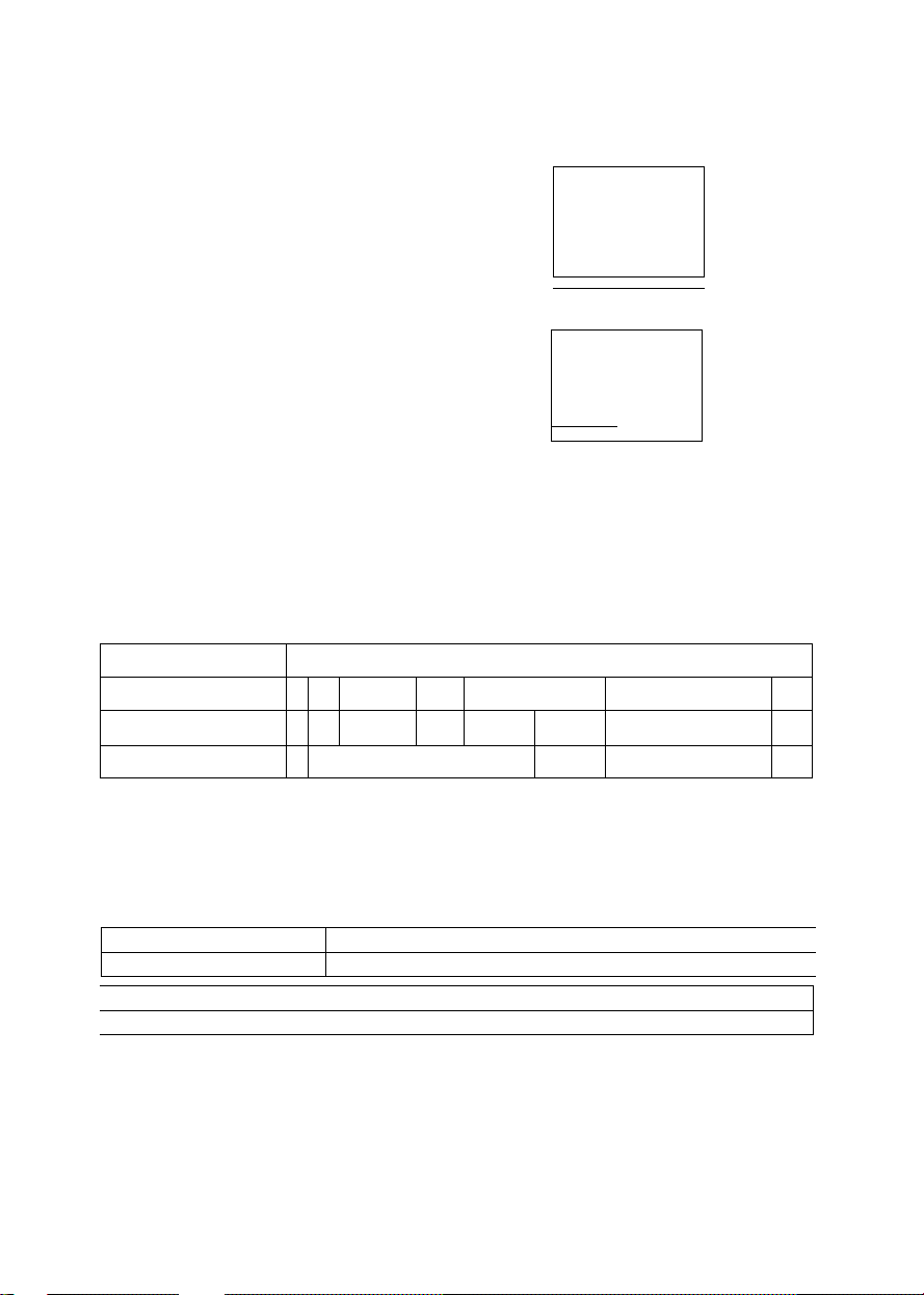
5 Set the month, day and year in this order.
Press to/C3to make the item to be set blink, then press Q / Q untii the desired
number appears. _ .
(O Q •>
> The day of the week is automatically displayed.
> You can set the calendar from the year 1992 to 2007.
6 Set the clock.
Press to make the next item blink and then press Q / Q to set AM or PM.
PresstO/CSto make the item blink and press Q / Q until the desired time appears.
Q
(O CE) ■»
Q
7 Press ENTER.
The moment you press ENTER, tiie clock starts.
Now the time is set and the normal screen resumes.
y———ror laiye
For larger number
CLOCK 8CT
or smaller number
CLOCK SET
7/ 4/im
Close the front cover.
8
To reset the clock
Proceed step 3 to 7.
Note
If the lithium battery is not installed, the clock will go back to *
disconnected.
' each time the power source is
Page 22
Watching TV
Receivable channels of this video recorder are:
VHF:2-13
UHF: 14-69
Cable TV : 1 (A-6). 98 (A-2). 99 (A-1), 14-36 (A to W). 66-125 (W+30 to W+84)
This unit is preset at the factory to receive certain channels (see chart on page 23.) If you want
to receive other channels, you need to preset them.
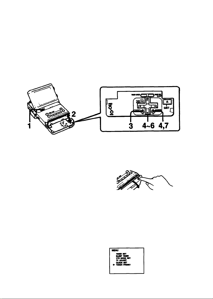
To Preset New Channels
----------------------
1 Turn the power on.
The power lamp lights.
If a TV program is not displayed, press
INPUT SELECT.
CMICIW* • VTSOMOrr
While pressing the green button,
slide TOWER to the right.
2 Open the front cover.
3 Press MENU.
The MENU display appears.
(SEq) .»
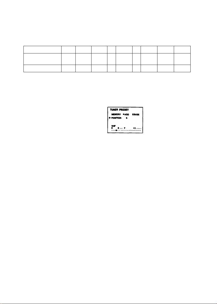
4 Press Q / Q until points to "TUNER PRESET', then press ENTER.
The TUNER PRESET display appears.
Upwards
0-
Downwards
0-'
POWER -Q-
^ fUNtR PMItT
sTT
--------
22
Page 23
Preset channels
Program position
Corresponding
channel
Number displayed
* UHF channels are preset around this number.
— Channels are not preset.
5 Press Q/ Q until^ points to "POSITION”,then pressQD/CStoselectthedesired
position. (EX. 5)
1
2-13
CATV
VHF
1
2-13
1
2-13
For smaller number
14-36
CATV
14-36
14-36
37 38-60 61
*
37 — 61 —
«
—
Q
(¿1 CiiD
g
For latter number
G Press Q until >■ points to the tuning indicator.
PressSD/USuntil the desired channel is tuned In.
Band indicator The VHF or UHF
For a smaller- indicator lights in sequence,
numbered channel
numbered c
TUtCR PRESET
Q
iiMiBai iHi'ffliH«iiii«ii‘iihiiii'iii ill' aai’
62-97
—
98
CATV98CATV
98
99
99
99
For a larger-
Q
Each time you press 03/, the adjacent channel is automatically tuned in.
Press until the desired channel appears and keep It for about 2 seconds before
proceeding next step.
If you want to preset more channels, repeat steps 5 to 6.
numbered channel
Tuning indicator Indicates the approximate
location of the channel scanned in the band.
7 Press ENTER.
8 Close the front
To change the order of the channel to be stored
Follow the above steos.
cover.
O'
Page 24
’Ll' ;
To Erase Channels
The erased program position skips when you press CHANNEL/INDEX
Example: To erase program position 11
1 Turn the power on.
The power lamp lights.
If a TV program is not displayed, press
INPUT SELECT.
----------------------nr
CAMEIU« • .«^VWONlOFF
While pressing the green button,
slide roWER to the right.
Open the front cover.
3 Press MENU.
The MENU display appears.
MENU
4 Press Q / Q until ^ points to “TUNER PRESET’, then press ENTER.
The TUNER PRESET display appears.
r>OWER -Q-
----------
24
1^-Upwards
Q-Oowrrwards
MENU
TMCR ttr
«UfPTMIR
VfR MOM SIT
TV AOJUST
CiOCN SfT
> TUNCR PRCStT
Page 25
5 Press Q/ Q until ^points to POSITION, then press (ia/C£>to select the channel
to be erased. (EX.11) —
CS
g
TUNER PRESET
MtMORV
^POsmoN it
VHP
i •
•AOO ERASE
7
..... ....
6 Press Q / ID until ^ points to CHANNEL, then press (13/ C3to select ERASE.
TUNER PRESET
PMeMony
AOO »ERASE
PONTIOM 11
VHP
s • • T 11
If you want to erase more channels, repeat ttie steps 5 and 6.
Q
7 Press ENTER.
To add the erased channels again
See “To Preset New Channels” on page 22.
Channel Allocation Chart
..........
.... ................. .
• -
Frequency (MHz) SO
VHFAJHF channels
CATV channels
VHF
2-6
M-
A-2~i
VHF
7-13
100 150 200 250 300 400 500 600 700 8(
J~W W + 30-W+84
Band indicator VHF
When the CHANNEL button is pressed, the above channels will be scanned from the lowest
frequency to the highest in sequence. By pressing the CHANNEL - button, the channels will be
scanned in reverse.
UHF14-69
UHF
10
Cable TV Channel Chart*
Cable TV systems use letters or numbers to designate channels. To tune in a channel, refer to
this chart.
Number on this TV
Corresponding CATV channel A-8 A-2 A-1 A B C D
24 25
23
K
J
Check with your local cable TV company for more complete information on the available
channels.
L M N O P
27 28
26
1 98
99 14
29 30 31 32
Q
15 16 17
R S T
34 35 36
33
18 19 20 21 22
E F G H 1
V
U
W Wt30
.................
........
......
Wt84
» The designation of the cable TV channels conforms to the EI/VNCTA recommendation.
Note
Pay cable TV systems use scrambled or encoded signals and require special converters
(decorders) besides the normal cable connections.
Page 26
26
Page 27

-y-TT
-----------
'. .',.1 : • '•
.......
".t i'l y.;.
■ •■■■-•libivi
■ ’ f - 4
5 Adjust the antenna for the best reception.
Pull out the base of №e telescopic antenna fully
before adjusting the antenna.
6 Adjust the volume and brightness.
. V
¡.It
i :i 1- !..
To decrease
volume
To turn off the TV
CAMEIM« • -i^VTROWOFF
To incre2ise For less For more
volume. brightness brightness
-
------------
POWER b
The power lamp goes out.
While pressing the green button, slide POWER to
the right.
To put the antenna away
Slide in the base of the telescopic antenna first,
then the center and point.
27
Page 28

To View a TV Program using SEEK function
Use the Seek function when:
- you do not know the channel number of the TV program you wish to view
- you want to use the unit in a moving car
Search for the program as follows.
1 Press SEEK.
The channel range display appears.
For VHF channels, press once. For UHF channels, press twice.
To restore the nomial display, press once more.
- ¥jvr\ »!-••>•. ■
Press CHANNEUINDEX W- to select the channel.
1ST
After selecting the channel, the channel range display goes out after a few seconds.
Repeat step 2 If you want to change the channel.
28
Page 29

To mute (turn oft) the picture
Press LCD ON/OFF.
The screen will be muted.
It is recommended to mute the picture when you view the
playback picture with another TV or monitor. The picture noise
of the TV or monitor is reduced. Battery life will also last
longer if you use the unit with the picture turned off. To restore
the picture on this unit, press LCD ON/OFF again.
Note
When no picture is displayed and the volume is low, or the
phones are connected, the unit appears to be turned off even
though it is not. Be sure to turn off the unit with the POWER
switch when it is not in use.
To display the channel number
Press DAT/\ SCREEN.
To make the on-screen display disappear,
press DATA SCREEN again.
After SEEK is pressed, the VHF or UHF
channel range is displayed instead of the
channel number, then goes off after a few
seconds.
DATA
SCREEN
□ ->
Press to mute
the picture.
Channel number
“Last channer memory function
• While you are watching TV programs, if the power source is disconnected or the battery pack
becomes exhausted, the unit turns off with the last channel being memorized.
When you turn on the unit again, the last channel appears on the screen.
The lithium battery must be installed for this function.
• The last channel memory function also works when the TV signal is cut off, for example, when
you go through a tunnel in a moving car.
• If the lithium battery becomes exhausted but the power source is connected, the last channel
memory function will still operate.
Page 30

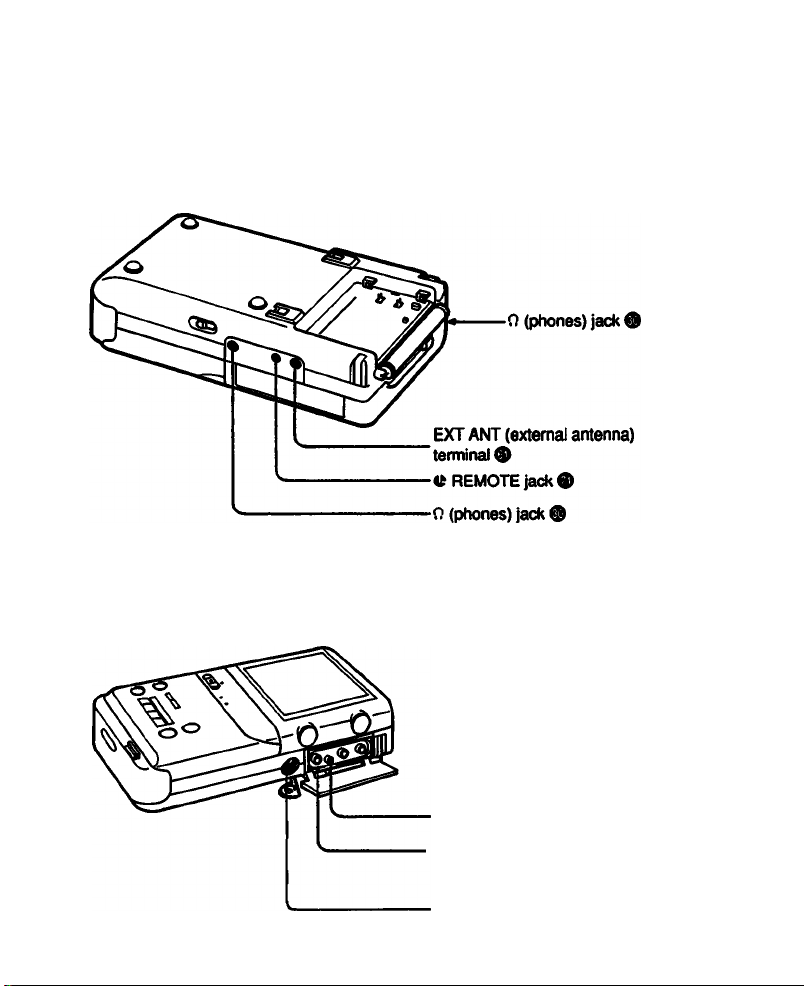
To Receive Stereo Programs
Connect the supplied stereo earphones to the 0 (phones) jack to listen to stereo sound. This
unit has two 0 (phones) jacks. Use each/both of them in accordance with the situation.
The speaker of this unit is monaural.
This unit is preset at the factory to receive stereo programs automatically. If the unit receives a
stereo program, the “STEREO* indication will appear on the screen and disappear after a few
seconds.
SICREO
To then
(phones) jack
n excessive noise is heard when receiving a stereo program
Set AUTO STEREO to OFF in the VTR MODE SET menu (see page 57). The sound is heard in
monaural but the noise is reduced.
Monaural sound is recommended when the unit is used in a moving car.
To restore stereo sound, set AUTO STEREO to ON in the VTR MODE SET menu (see page
57).
To Recelvo SAP (Second Audio Program) Braodcast
Set AUTO SAP to ON in the VTR MODE SET menu (see page 57).
SAP sound is automatically received when SAP is broadcast.
When SAP is not broadcast, monaural or stereo sound is received.
30
Page 31

Adjust the picture and sound to your preference.
To adjust the picture
Open the front cover and press
MENU. t
I MENU
2 Press Q / Q until ^ points to
TV ADJUST, then press
ENTER.
3 Press Q / Q until ^ points
the desired Hem (COLOR,
STANDARD).
rtsto
.HUE, LI
S-'
upwards
Downwards
n
TV ADJUST
SSS""—
t:
.............
4 Adjust the level of the Item.
Each time (O/CS is pressed, each item will be adjusted as shown
below.
COLOR I I HUE
To adjust the color intensity To adjust the skin tone
TV ADJUST
► OOLOR COUM
Mue
tTANDARO
LIGHT PARK
for less for more to make skin to make skin
color intensity color intensity tones redish tones greenish
TV ADJUST
STANOAHD
MtO ORCDI
MENU
TMEII MT
...............
—Each press moves
HZ
After changing COLOR
and/or HUE, you can
readjust them to the
standard levels by setting
► to STANDARD.
-Indicates the level
of adjustment
by one line.
(O Q
STANDARD |
5 Press ENTER.
Close the front cover.
31
Page 32

To Activate the various Sound Effects
You can listen to dynamic bass and surround sound by using the supplied stereo earphones.
Refer to the table telow for each function.
SURR (surround)
function
Headphone
Speaker
Line out
For the VOCAL REDUCTiON function, see page 48.
Activate the desired function by pressing SURR/MEGA BASS.
“SURROUND* or ‘MEGA BASS' indication will appear on the screen and disappear after a few
seconds.
To listen to dynamic bass sound
Select MEGA BASS function.
To listen to surround sound
Select SURR (surround) function.
(Only when receiving stereo TV program or playing back the stereo sound)
Active
Not active
Not active
MEGA BASS
function
Active
Not active
Not active
VOCAL REDUCTION
function
Active
Active
Active
> SURR (surround)/MEGA BASS function is not active simultaneously when using VOCAL
REDUCTION function.
32
Page 33

íHMiiHiiHMi&iaiÉiÉiMiwáLÉ
You can set the unit to turn off automatically after a certain amount of time, after as short as 30
minutes or as long as 5 hours, while viewing a TV program, video playback, or while recording.
Example: To turn off the TV after 2 hours
1 Press DATA SCREEN to make sure the clock is set correctly.
2 Press MENU while watching TV.
The MENU display appears.
3 Press Q / Q until ^ points to
"SLEEP TIMER”, then press ENTER.
The SLEEP TIMER display appears.
4 Press Q / Q to set the desired tiiiie
duration, then press ENTER. (EX: 2
hours)
The TV will turn off automatically after 2
hours.
If the clock is not set, the "CLOCK SET"
indication will appear on the screen. Set
the date and clock (see page 18.)
For shorter duration
To cancel the SLEEP timer
In step 4 above, press Q / Q until the
display appears, then press ENTER.
The SLEEP timer can also be cancelled by
turning off the unit with the POWER switch.
To check the remaining time
.ñ
g
For longer duration
MENU
ntm MT
» fICIPTIIICII
vm MOM MT
TV «OJUfr
OOCK Mr
TVNIfI PMSn
Time duration changes up to 5 hours in
steps of 30 minutes.
Press DATA SCREEN.
DATA
SCREEN
Note
When you use the unit with rechargeable batteries,
the unit may turn off before the selected time because
the batteries are exhausted.
-The unit will turn off after
about 1 hour and 52 minutes.
33
Page 34

Using This UnitasaVCR
Make sure that the power source is connected to the unit.
To insert a Cassette
1 Open the front cover, then press EJECT.
The cassette holder slides to open automatically.
Do not open the cassette holder forcibly.
Q
I
EJEC T
2 Insert the cassette with the window side facing up.
3 Press the I PUSH I mark.
The cassette holder slides to close automatically.
When you press EJECT, power is supplied artd the cassette holder opens even if the power is
turned off. When the cassette holder opens, the power goes off automatically. Slide POWER if
you want to continue operation.
34
Page 35

ai cassette
1 Press EJECT.
Make sure the tape is not running.
2 Remove the cassette.
3 Press the I PUSH I mark.
The cassette holder slides to close automatically.
Note
Do not open the cassette holder while the unit is in the vertical position. If you do, the cassette
may fall out of the holder and be damaged.
To Prevent Accidental Erasure
Slide the tab on the cassette to
expose the red mark. This will prevent
accidental recording.
If you try to record with the red mark
exposed, the “CASSETTE” indication
appears on the screen, and you
cannot record. To re-record on this
tape, slide the tab back out covering
the red mark.
Notes on opening and closing the cassette holder
• Do not insert your finger into the cabinet when the cassette holder is open.
• Be careful not to get your finger caught in the cassette holder.
D
Recording cannot
be made.
a
Recording can
be made.
Notes on the cassette
• Store cassettes in their cases when they are not being used and keep them in an upright
position to prevent intrusion of dust and uneven winding.
• Always insert the cassette in the correct position.
• Never insert anything in the small holes on the rear of the cassette.
• Remove the cassette from the video TV recorder when not in use.
Page 36

You can record a TV program while viewing it. For optimal picture and sound quality, connecting
an external antenna is recommended. (See page 60.)
6 3
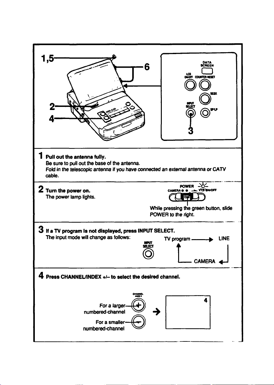
1 Turn the power on.
The POWER lamp lights.
CAMERA*
While pressirig the green button,
slide POWER to the right.
2 If the TV program is not displayed, press INPUT SELECT repeatedly until the TV
program Is displayed.
The input mode will change as follows;
When the tape is recorded to the end
The tape stops automatically, but the unit is not turned off. If you are not going to continue
operation, turn the power off with the POWER switch.
About the recorded sound
The VOL control setting has no effect on the recording level.
36
ww TV program
POWER
• VTMONK>fF
l_ CAMERA 4-J
LINE
Page 37

3 Select the desired TV channel. (See page 26.)
Adjust the telescopic antenna (or the best reception. (See page 27.)
4 Insert the cassette. (See page 34.)
S Select the recording mode, SP or LP.
The recording time of a cassette in the LP mode is twice as long
as that In the SP mode. For better picture and sound quality, set
toSP.
6 Slide REC to the right.
REC lamp lights and the recording starts.
REC
SMJ>
For this on-screen display,
To stop recording for a moment
Press II.
To resume recording
Press II again.
(If PAUSE is not pressed again for about 5 minutes, the
pause mode will be released automatically and the unit will
stop. This is to protect the video heads and recording will
stop.)
itigrhg|№ecHat^ during recording
Set the unit in the recording pause mode and then select another channel. You cannot watch
another program while recording.
pMhen reoordii^ from the beginning ol a tape
Run the video TV recorder for about 15 seconds at the beginning of a cassette before recording.
This will prevent missing the starting point or having any previously recorded pictures appear
when playing back on another video cassette recorder.
To stop recording
Press □.
Page 38

When recording starts
The starting point is marked on the tape automatically and “INDEX MARK* is displayed on the
screen (see page 51.) When you release the recording pause mode and start recording again,
the starting point is not marked. The index mark helps you to find the point where recording
begins on a tape.
Recording/playback time
Two tape speeds can be selected with the SP/LP recording time selector.
The recording time in the LP mode is twice as long as that in the SP mode. For better picture
and sound, recording in the SP mode is recommended. During playback, the mode in which the
tape was recorded is selected automatically.
Cassette and their recording time
There are two formats for 8mm video recording, NTSC and PAL. Video cassette tapes are
made to correspond to one of these formats. Use NTSC format cassette tapes for this unit. You
will find *P6” on the package of NTSC cassettes.
Note
If you record with this unit on a tape that has been recorded in the PCM mode, and if you play
back this tape on a VCR with PCM function, the sound may be cut off occasionaliy. In this case,
set the audio monitor switch of the VCR to the standard position.
To stop recording automaticaily after a oertain time —Quick timer
Use the SLEEP timer during recording. You can leave the unit function when you go to bed or
when you go out, etc.
The unit will be turned off automatically at the preset time. For operation, see page 33.
Are you having trouble?
Symptom Possible cause
The red mark on the
“CASSETTE"
indication is
displayed when
you slide the
REC switch.
cassette is exposed.
The tape is at its
end.
No cassette is
inserted.
Correction
Slide the tab to
cover the red mark
or use a new
cassette.
Rewind the tape or
use a new cassette.
Insert a cassette.
Page 39

Using the Tape Counter
During recording or playback, the digits on the counter indicate the actual recording or (Payback
time.
By noting the counter reading at a particular point, you can easily find that point later by
referring to the tape counter.
Notes
• The counter reading and the point on the tape may not correspond exactly. Use the counter as
a guide.
• There will be a time lag of several seconds on the counter reading after repeated fast-forward
and rewind operations.
• There will also be a time lag of several seconds when a tape recorded in both the LP or SP
modes or a tape having a blank portion between the recorded portions is played back.
• When you use non-recorded tape, counter does not ooerate.
Page 40

To record stereo programs
Make sure AUTO STEREO is set to ON in the VTR MODE SET menu (see page 57).
You can record stereo programs in stereo, and monaurai programs in monaural.
This unit is preset at the factory to record stereo programs in stereo automatically.
To record stereo programs in monaural, set AUTO STEREO to OFF in the VTR MODE SET
menu (see page 57).
Make sure AUTO SAP in the VTR MODE SET menu is set to OFF before recording. If AUTO
SAP is set to on, SAP sound is recorded when SAP is broadcast during stereo programs.
______
___
To record SAP (Second Audio Program) broadcast _ _
To record SAP sound on the normal audio track, set AUTO SAP to ON in the VTR MODE SET
menu.
This unit is preset at the factory with AUTO SAP set to OFF.
Normaily, set AUTO SAP to this position (OFF).
The main sound is recorded on the normal track.
40
Page 41

You can preset up to 6 recordings as much as one month* in advance.
For better recording of picture and sound, use of an external antenna is recommended. See
page 60.
* Recording from today to one month later
If today is Juiy 4th, you can set the timer to record a program broadcast between today and
August 3rd.
I the timer
• Make sure that the power is suppiied. (Is the battery pack fully charged? For long recording,
be sure to use the AC power source.)
• Set the date and clock (see page 18.)
• Insert a cassette (see page 34.) Make sure that the safety tab is siid in to cover the red mark.
• if recording a stereo program, make sure that the AUTO STEREO is set to ON, AUTO SAP is
set to OFF in the VTR MODE SET menu (see page 57.)
Example: To preset a timer-recording of channei 8 from 8:00 PM to 9:45 PM on Saturday,
July 4,1992 in SP mode.
u. CD
«•Of* couMCfmisct
-| TIMER REC lamp
TIMER CLEAR ^ OR O
(see page 46.) O J<0***0
1 Turn the power on and open the front cover,
POWER
CAMERA • • Vt* IMVOFF
While pressing the green button,
slide TOWER to the right.
TIMER CHECK
mai
%
41
Page 42

2 Press INPUT SELECT.
Each time you press INPUT SELECT, the display will change as follows.
Make sure a TV program is displayed on the screen.
TV Program
MPUT
SELECT
^
---------
3 Press MENU, then press Q / Q until ^ points to TIMER SET.
MENU
--------------
CAMERA ^
LINE
4 Press ENTER.
The TIMER SET display appears.
5 Set the date, tunvon time, tunvoff time. (Set AM, PM also.)
Press C3to make the item to be changed blink and press Q / Q until the desired
dateAime appears. Foneard
P
Reverse
To change an item which is already set in n
PressSJ/CDto make the item to be changed blinkand change itwith U / Q .
6 Press Q / Q to set the channel for recording TV program.
For larger channel number display
IWER 8CT
:::: : ;;
TWER SET l>4 tat
OAff ON OfP CN
OATt «(M .
m Mw
turn«
MIIIAt
OPT CN
SAt
-
-
42
For smaller channel number display
Page 43

7 Press Q / Q to select the recording tape speed (SP or LP),
then press csto finish presetting.
MTI ON OPP CN. I
0
g
8 To preset other programs, press Q to move N- to the next ilne -f~ - - and
rep^ steps 5 to 7.
9 Press ENTER or make sure that ^ points to the first iine.
10 Press TiMER REC ON/OFF.
TIMER REC lamp lights and the unit turns off.
W:«* Mi:49 •
I -^TWERHEC
ONOFF
'1'
11 Close the front cover.
At the preset tum-on time, the recording wili start automaticaity and will stop at the
preset turn-off time.
To stop an on-going timer recording
Press TIMER REC ON/OFF. The recording stops.
Page 44

Every Week Recording and Every Day Recording
You can preset to record the same program every day or the same program on a specific day of
every week.
Press Q / Q , and the indicator will change as follows.
For every week recording or everyday recording, press Q to set the date quickly.
MON-FRI
(Every day except Saturday
and Sunday)
When the presettings of timer recordings overlap
Example
'ill be
i Wi
recorded
■ > EVERY SAT ◄
Will be cut off
Will be recorded
-i......................
Will be cleared
Program^l Program 2
I ,
Program 1: The recording will stop before the program finishes.
Program 2; The program will be recorded completely.
Program 3: The presetting will be cancelled.
-------
EVERY SUN^-
•8/3
(1 month later)
Page 45

• If the recording start time of one program comes before the recording of the other
program is finished
The recording of program 2 begins before program 1 is finished.
• If the recording start time of two programs are the same
The program which is preset on the upper iine
CHECK display will be recorded and the other program will be cancelled.
-------
in the TIMER SET or TIMER
Note
If the recording start time of the second program is the same as the recording end time
of the first program
The last 20 seconds of the first program will not be recorded.
^CSiikng tl^r recording
Both picture and sound will be muted. To listen to the sound and watch the picture, press LCD
ON/OFF.
No buttons other than TIMER REC ON/OFF and TIMER CHECK are operable.
^oaet thp timw while the tape is running _
Date, starting and ending time, etc. can also be set during playback or recording. However,
TIMER REC ON/OFF button is not operable.
^a power Interruption occurs when the unit is connected to the AC power source
Recording stops. Recording starts again after the power is resupplied. When a power
interruption occurs during the timer recording standby mode and the power is resupplied, the
timer settings will not be affected as long as the lithium battery is installed.
record the end of the tape
Set the starting and ending time the same. When the tape reaches the end, recording will stop
and the power goes off.
Page 46

To Check the Contents of Preset Timer Setting
When the unit is in timer recording standby mode or operating on timer recording
Press TIMER CHECK. The TIMER REC display showing the preset timer settings will appear on
the screen. If the unit is turned off, turn on the unit, then press TIMER CHECK.
The TIMER CHECK display will appear.
To turn off the TIMER REC display, press TIMER CHECK again.
ntERCHKK
To Change the Timer Settings
When the unit is in timer recording standby mode or operating on timer recording
1 Release the timer recording mode by pressing TIMER REC ON/OFF.
2 Turn on the unit.
3 Preset timer again. (See the procedures on page 41 to 43.)
To Cancel the Timer Setting
Release the timer recording mode by pressing TIMER REC ON/OFF.
Turn on the unit and select TIMER SET in the menu display. In the TIMER SET display, press
Q / Q so that P- points to the setting to be cleared and press TIMER CLEAR. The setting will
be cleared and -/- indication resumes.
To Operate the Unit After Setting the Timer
1 Press TIMER REC ONADFF.
The TIMER REC lamp goes off.
2 Operate the unit.
3 After using it, press TIMER REC ONADFF to turn on the TIMER REC lamp.
The unit turns off and enters timer recording standby nrade.
Page 47

1 Turn the power on.
The POWER lamp lights.
eco
While pressing the green button, slide
POWER to the right.
PO'
ifTER -P-
CAMERA*
P51«
2 Insert a recorded tape (see page 34.)
3 Press > to start playback.
4 Adjust the volume and the brightness.
To decrease To increase For less For more
volume ^^^^^volume brightness^^^^^brightness
To stop playback
Presso.
To rewind the tape
Press •
To advance the tape
Page 48

7b rawfr^ the tape and play It back automatically — Auto play
While pressingpresso.
The “AUTO" indication appears.
To mute the ptcture
Press LCD ON/OFF. To restore the picture, press LCD ON/OFF again.
To adjust^e plcture_
Adjust the BRIGHT control (see page 47.)
Adjust the COLOR and HUE in the TV ADJUST menu (see page 31.)
___
__________
To atop playback at the desired time
Use the SLEEP function.
The unit goes off at the preset time, (see page 33.)
When a tape recorded In stereo mode is play-back
The “STEREO” indication appears.
To listen to the stereo sound, use the stereo phones.
Playtack o^tapes recorM In HW video system
This unit plays back tapes recorded in HI8* video system.
However, please note the folloviring important conditions.
Hi8 recording will be played back with standard 8mm picture quality.
This unit cannot record with Hi8 picture quality.
Noise may appear in the picture when you play back a tape recorded in Hi8 LP mode.
* HI8 is the 8mm recording option found on selected high end 8mm camcorders and decks.
To Reduce the Vocal Sound
During playing back of the tape recorded in stereo mode (except PCM stereo mode), press
VOCAL REDUCTION to reduce the vocal sound.
The “VOCAL REDUCTION“ indication will appear on the screen and disappear after a few
seconds.
Use this function to enjoy singing while viewing a music tape.
• This function is not activated when a tape is recorded in monaural mode.
• This function is effective only for a tape on which vocal sound is recorded in the center
position.
• If the vocal reducing function is activated, the SURR(surround) function or MEGA BASS
function is not activated.
48
Page 49

Various piayt>ack Modes—CRYSTAL-CLEAR still/slow/pictute search on LCD
To resume normal
playback, press >
To stop the tape
for a moment—Still
picture
During
playback
MUSE
II ^
or II. This mode will
be automatically
released and
playback will resume
after five minutes.
To view the slow
playback picture
To locate a
particular point
During
playback
During
playback
SLOW
!►
REW
To resume normal
while viewing the
picture—Picture
search
To view the picture
During
playback
While
rewinding
REW
•«4S
at high speed—FR
picture search
While fast
fonvarding
epp-
'‘ifsbeiBks appear In the still and slow playback mode
Adjust the picture as follows:
1 Playback the slow motion picture.
2 Select VTR MODE SET in the MENU display.
Adjust the picture so that the noise does not appear by adjusting SLOW TRACKING
item in the VTR MODE SET menu.
For details about the procedures to adjust slow TRACKING in the VTR MODE SET menu, see
page 57.
playback, press >.
When you release
the button, the unit
will return to the
previous mode.
fwmn the playback picture Is viewed on another TV or monitor
The horizontal bands appear in the still, slow, picture search and FR picture searcn mooes.
Noise appears in the still and slow modes. To reduce the horizontal bands, press LCD ON/OFF
button to mute the picture of this unit.
Note on ttie CRYSTAL-CLEAR still/slow/picture search on LCD
Noiseless pictures can be viewed in the still, slow and picture search modes, owing to the
characteristics of the liquid crystal.
Page 50

ismBiiiBsaiisomEi
You can repeat playback cf the desired portion up to 5 times during playback.
Decide the start point (A) and end point (B) to be repeated by pressing A - B REPEAT. The
desired portion i^ll be repeatedly played back for five times and then enter the normal playback
mode.
1 During playback, press A - B REPEAT to decide the playback start point (A).
ABRB>EAT
^S^A-B REPEAT
A is memorized.
2 Press A - B REPEAT again to decide the
playback end point (B).
B is memorized. The ta^ is rewound
automatically to the start point (A) and playback
starts. The desired portion (from A to B) will be ABRB»EAT
played back for 5 times repeatedly, the unit then
enters the normal playback mode.
I ^
«.■ REPEAT S
Press DATA SCREEN to display how many
times playback will repeat.
To release the A-B repeat function before completing playback 5 times.
Press □ or >.
50
B is memorized
The remaining number of times for
playback to be repeated excluding
on-going playback
Page 51

Indexes can be recorded on the tape. Using indexes, you can find the desired scene quickly.
There are two kinds of indexes as follows:
(S INDEX (conventional type)
Indexes on your video tape which you can
enter and erase during recording or playback
operation. You can find the desired scene by
designating the location of the desired index,
(e.g. second index in the
forward direction, etc.)
(reverse direction) (forward direction)
III CHAPTER (prerecorded Index for software)
Indexes that are already recorded on the
commercially available video software.
The indexes are already recorded, and you
cannot enter or erase them. Each index has
the chapter number so you can search the
desired part by designating the number.
Chapter number
7^
Beginning
Current position 10
f
TB Enter an Index on a Tape
When you start recording with the REC switch or when timer-recording is started, the
index signal is automatically recorded for a few seconds*. (Indexes are not recorded
when recording with a camera.)
End
Index signal
INDEX MARK-
INDEX ERASE-
Beginning End
s®
Cp
'Center ap Index during recording or playback
During the recording/playback
Press INDEX MARK.
The index signal is recorded for a few seconds*.
INDEX
During the recording/piayback pause mode
Press INDEX MARK.
The ‘INDEX MARK STANDBY” indication appears on the screen
and the unit enters the index mark standby mode. Press II to
release the pause mode. The index signal is automatically recorded.
During the playback mode, a black band appears on the screen.
But this band is not recorded. In this case, no sound is heard.
* For SP mode: about 10 seconds
Black band
For LP mode-, about 18 seconds
Note
Leave at least two minutes between each index. If an interval is too short, you may not be able
to find or scan indexes correctly.
51
Page 52

To Find a Desired index—index Search
When you know the location or chapter number of the desired index, you can
number to find the desired part of the tape.
1 Press INDEX once during playback or the
playback pause mode.
The unit enters the index standby mode.
2 Press CHANNEL/INDEX * *t- repeatedly
until the desired index number appears on
the screen.
The tape is rewourKl or fast forwarded to the
designated index number position, then
pla^ck starts.
INDEX
To correct the chapter or index number
When the *CHAP* or 'INDEX* indications are displayed, you can correct the number with the
CHANNEL/INDEX +/- button.
Notes
• Even with a video software which has prerecorded indexes, the indication is 'INDEX
SEARCH' until the tape is played back.
52 • If you designate *CHAPTER 0' in step 2 above, *CHAPTER 1’ will be played back.
Page 53

51 INDEX (conventional type) 111 CHAPTEH(pwwcofdwl Index ter soBiiMfe)
Example: designating the second index in
the reverse direction
Example: designating chapter number 7
•43
►14► 2
PlayJk Remind Current position
MOCX
SEARCH •
Moex
Determine the number of indexes between the
current position and the desired index.
Select the appropriate number.
Press + lor ► (forward) direction, - for ◄
(reverse) direction.
STANDBY
•
^ ^ ^
111:_t
Current position
Current chapter
number
Select the chapter number reffering to the
number on the jacket of the cassette tape.
Press -f for a higher number, and - for a
iower number.
CHARTER
SEARCH 1
STANDBY
CHAPTER
SEARCH 7
When playback starts, the indication will
disappear after about 10 seconds.
When piayback starts, the indication
disappears after about 10 seconds.
Index search does not function
If an interval between indexes is less than two minutes. Leave an interval of at least two minutes
between indexes.
Page 54

To Scan Each Index Sequentially
The beginning of each index/chapter is played back for about 10 seconds sequentially. Start
playback at the desired index/chapter.
Playback for about 10 seconds
<|>| |>| <4 |D>| ►► |0|
(Rewind) (Fast forward)
Playback for about 10 seconds
^ |C>| ►► !(>[►►
To correct the direction of index scan
Press INDEX -/+ during index scanning.
Index scan does not function
If an interval between indexes is less than two minutes. Leave an interval of at least two minutes
between indexes.
Page 55

If you do not press > during index scanning, the tape will be rewound to the beginning of
the tape or fast forwarded to the end of the taoe.
Page 56

To Erase an Index
1 Search for the Index to be erased. (See page 52 to 55).
2 Press ERASE.
After playback starts, press the button while the following indications on the screen.
INDEX
SEARCH S
MOEX
5
ERASE
Black band —
When you press ERASE, the tape is rewound to the beginning of the index signal,
then the index signal is erased. On the screen, the indication ‘INDEX ERASE* and the
black band appear.
Note
Do not press any of the tape transport buttons while entering/erasing an index. If it is done,
entering/erasing will not be completed.
Notes on the index signal
• You cannot enter an index signal on a commercially available video software or on a cassette
whose safety tab is slid out.
• You cannot erase an index signal which is prerecorded on a commercially available video
software.
• The index signal may not be erased in the following cases:
- When the index signal is recorded on a video camera recorder or other VCRs, and you wish
to erase it on this unit.
- When the index signal is recorded on this unit, and you wish to erase it on a video camera
recorder or other VCRs.
• To erase the index signal completely, use the equipment you used to enter the index signal.
MOEX
MOEX
OCAN»»^
MOEX
ERASE
56
Page 57

IT
You can preset 4 items by setting in the VTR MODE SET menu dispiay.
You can use the unit with the normai setting preset at the factory, if you want to change the
setting, proceed the following steps to change the desired items.
Setting the Mode
%
f
1 Display the MENU display on the screen.
(See steps 1 to 3 on page 22.)
2 Press Q / Q to set ►points to VTR MODE SET.
3 Press ENTER.
VTR MODE SET menu appears on the screen.
4 Set the desired item.
Press Q / Q to set ► points to the desired item.
Then press so/ Oto set • to the desired position.
For details on the items, refer to the next page.
5 Press ENTER.
The normal screen resumes.
MENU
» TMER SET
«.EtP xmm
vrn MODE Etr
VTR MOOK 86T
AtnOtlEMO
AUTO »AP
EMT ON OOPP
8LOWTIUCIQN8 tlOW
• ON OPP
ON oOPP
57
Page 58

Display mode
AUTO
STEREO
•: Preset
positton
• ON To receive stereo programs
Setting purpose
in stereo
When Is the setting
needed?
Normally set to this position
OFF
AUTO SAP
• OFF
EDIT
• OFF
SLOW
TRACKING —
ON
ON
To receive stereo programs
in monaural
To receive SAP sound
automaticaily
In this setting, stereo or
monaural sound is received
when SAP is not
broadcasted.
To receive stereo or
monaural program
To activate the edit mode
Not to activate the edit mode
To adjust the tracking for
slow motion playback
picture
When excessive noise is
heard while receiving stereo
program
To receive SAP broadcast
Normally set to this position.
To reduce the deterioration
in picture and sound during
editing
Normally set to this position.
When streaks appear during
slow playback mode
58
ÉfS
Page 59

Connecting
Other Equipment
if you cannot obtain satisfactory reception with the teiescopic antenna, or when reocrding TV
programs, use an outdoor antenna. For viewing CATV channels, connect the CATV cable.
CATV cable-
UHF antenna
(Channel 14-69)
Pay cable
TV decoder
Miniplug
VHF antenna
(Channel 2-13)
Mixer
I I
Signai spiitter
(supplied)
To antenna terminai
GV-500
For connection, you can aiso use the antenna connector EAC-40, the signal splitter EAC-45, the
antenna cord CCD-6M, and CCD-2 (not supplied.)
Notes
• Before connecting the antennas, turn off the unit.
• Make connections firmiy. A ioose connection may cause a distorted picture.
• When using the unit in a car, use the optional VCA-3W or VCA-4E car antenna, etc. For
details, refer to the instruction manual of the car antenna.
59
Page 60

Notes on the VIDEO/AUDIOIN/OUT Jacks
The VIOEO/AUDIO IN/OUT jacks are automatically set to the input or output jacks according to
the operating condition of the unit.
Refer to the following diagram:
Mode selected with
INPUT SELECT button
TUNERfTV program)
LINE»
CAMERA
• When the LINE mode is selected with INPUT SELECT, the
INPUT or OUTPUT indication appears with LINE.
Note
When the LINE OUT jacks of other equipment are connected to the VIDEO/AUDIO IN/OUT
jacks on this unit, and signals are output from the jacks of the other equipment to this unit,
the picture and sound of the other equipment may be distorted.
In such case, turn off the power of this unit or disconnect the other equipment.
Stop or recording mode Playback mode
output output
input output
output
output
60
Page 61

Camera Recording-Controlling from the Camera
By connecting a Video Camera CCD-G1 (not suppiied), you can control the recording from the
camera. You can hold the camera and keep this unit in a carrying case while recording.
For details, refer to the instruction manual of the video camera.
Connection
CCD-G1
rgpt n ToCAMEFIA
• Select the recording mode (SP/LP).
Note
The sound will be recorded in monaural.
Camera
connector
Camera cable
supplied with
the CCD-G1
connector
: Signal flow
Align atjd insert
To remove, pull it out
by holding here
Page 62

Hecotding wHh CCD-G1
Insert the cassette.
2 Set POWER of this unH to CAMERA.
The power of this unit is tumdd on, and the POWER lamp
lights. This unit automatically becomes in the recording
pause mode. To have the picture on the screen of this unit
press LCD ON/OFF.
Note
Check that the POWER lamp lights.
If you leave the unit in the recording pause mode for 5
minutes or longer, the unit will be automatically turned off.
To resume the recording pause mode, slide POWER to the
right once, then reset POWER to the CAMERA position
While pressing the
green button, slide
POWER to the left
3 start recording.
Press REC START/STOP of the camera.
To index the recording starting point or the desired point, press MARK of this unit,
(seepage 51.)
To stop recording for a moment
Press REC START/STOP of the camera. Press it again to start recording.
To stop recording
Turn the power off of this unit by setting POWER to the center position.
Playing back the newly recorded pictures
pa fER
.vnottorr
1 Turn the power on of this unit. While pressing the green —
The POWER lamp lights. button, slide POWER to the
right.
PO\«R
u* I -^vmbNiorr
\l/
2 Press of this unit to rewind the tape.
3 Press □ of this unit.
Press > of this unit
Caution
Do not operate this unit for long periods if heat cannot easily escape. Internal heat build-up may
occur which can cause the unit to malfunction.
When the POWER switch is set to CAMERA, the operable buttons are:
POWER switch, EJECT button, LCD ON/OFF button, DATA SCREEN button, COUNTER
2
RESET button, INDEX MARK button, and SP/LP recording time selector.
Page 63

:!"■ '
....
......
dEiiSS
■ '■ :y'^ ■ /: ■ ¡:--■ -.E;viS;Ei,>,v:;ii;.-r-•■■ iVU^.i|-■'
Camera Recoding-Controlling from This Unit
By connecting the video camera CCD-G1 {not supplied), it is possibie to record with this unit
whiie using the camera in a distant piace. For detaiis, refer to the instruction manuai of the video
camera.
Camera
connector
Camera cable |
supplied with
the CCD-Q1
To CAMERA
connector
• Select the recording mode (SP/LP).
Note
The sound will be recorded in monaural.
Align and Insert
To remove, pull it out
by holding here.
»■: Signal flow
Iteicottllng
1 Turn the power on of this unit
The POWER lamp lights.
2 Press the INPUT SELECT button of this unit to
dispiay “CAMERA” on the screen.
The STEREO indication appears. The picture to be
recorded appears on the screen. If the focus or color
need adjustments, adjust them on the camera. To have
the picture disappear, press LCD ON/OFF.
3 Slide the REC switch of this unit
Recording starts.
To stop recording for a moment
Press II of this unit
To stop recording
Press Oof this unit
While pressing the green button,
slide POWER to the right.
^•fniOHIOFr
BEC—
TI;E|I^
-9:
63
Page 64

Playing back the newly recorded pictures
1 Pressto rewind the tape.
Pressa.
Press >.
Recording with a camera from a distant place
Use the pan filter HVR-200 (not supplied) for camera recording from a distant place, a maximum
distance of S m.
To listen to the sound that is being recorded
While recording, no sound is heard from the speaker. Connect the supplied stereo earphones to
either of 0 (phones) jacks to listen to the sound.
To start camera recording at the desired time
You can record a desired scene at a designated time, for example, a train passing by at a
certain time. To set the timer, see page 41. The recording will start automatically at the time you
set.
64
Page 65

Using Th|s Unit as a 8 mm Video Camera Recorder Monitor
With the following connection, you can view pictures being recorded by the connected video
camera recorder. Also you can view the playback pictures from the video camera recorder on
this unit.
Connection
If the video camera recorder is stereo
to video output jj ft audio output
„to AUDIO L (white)
VMC-810S/820S
(not supplied)
This unit operates in the stereo mode automatically.
If the video camera recorder Is monaural
to audio A A to video output VMC-710^20M
output f y (not supplied) ^ viDEO (yellow)
This unit operates in the monaural mode automatically to AUDIO L (black)
Operation
: Signal flow
to VIDEO (yellow)
to AUDIO R (red)
1 Turn the power on.
The POWER lamp lights.
While pressing the green button,
slide POWER to the right.
2 Press INPUT SELECT to display “LINE” on the screen.
3 Operate the video camera recorder.
POWER
•
____ WPOWOfF
Page 66

¥№en connecting both a video camera recorder and a vkleo camera
Set each unit to different angles, then, using INPUT SELECT, switch the picture to be
recorded on this unit.
: Signal flow
CAMERA
INPUT SELECT button
Switch to CAMERA or LINE.
(Switch when in REC PAUSE mode.)
to video/audio output
Video camera recorder
66
Page 67

To Connéct Another TV or Color Monitor
If you connect this unit to another TV or color monitor, you can view the playback pictures or the
selected TV program on a larger screen and listen to the dynamic sound.
In this case, mute the picture of GV-SOO by pressing the LCD ON/OFF button to reduce
horizontal bands and noise in the picture of the TV or color monitor during various playback
modes.
To connect a TV/fnonItor with video and audio inputs
Monitor (stereo)
TV (monaural)
VMC-810S/820S
(not supplied)
: Signal flow
GV-500
to VIDEO (yellow)
I AUDIO L (white;
to AUDIO R (red)
GV-500
to VIDEO (yellow)
VMC-710M/720M
(not supplied)
to AUDIO L (black)
Note
When connecting only to the AUDIO L jack, the L and R sounds are automatically mixed and
always output is monaural.
Page 68

Note on the RRJ-89UCKA RFU kit
The RFU-89UCKA includes the (ollowing accessories:
- RFU adaptor (1)
- Antenna selector (1 )
- Antenna selector adaptor (1 )
Channel tor VCR
To view the playback picture of this unit, set the selector of the RFU adaptor to channel 3 or 4,
whichever channel is not active in your area, and select the same channel on the connected TV.
'^ connect the RFU adaptor
68
to AUolO L
to RFU DC OUT
to VIDEO
RF OUT connector
-■cniU ^H^to your TV
If the VHF input terminal of your TV
is a 300-ohm twin-lead plug, use the
-a
antenna selector adaptor supplied
with the RFU kit.
RFU unit selector
Setto3CH or4CH.
Page 69

You can edit tapes by connecting another VCR (8mm, Beta or VMS format) with video/audio
input.
f^to Edit from Another VCR to This Unit
If the VCR to be connected has a monaural audio output only, use a commercially available
connecting cord such as the VMC-710M/720M. In this case, connect to the AUDIO L and
VIDEO jacks.
69
Page 70

iiiiMfii'itfTjvaia
Operation
1 Turn the power on of this unit.
The POWER lamp lights.
2 Insert the cassette.
3 Press INPUT SELECT so that the “UNE”
indication appears.
MRi
While pressing green button,
slide POWER to the right.
4 Select the recording mode (SP/LP) by pressing
the SP/LP recording time selector.
5 Play back the tape on another VCR and press the n (PAUSE) button at the point
you want to start playing back.
G Set this unit in the recording pause mode.
7 Release the II (PAUSE) buttons on both units.
8 After editing Is completed, press the □ (STOP) buttons on both units to stop
recording.
$PIU>
ro
Page 71

To edit from the VCR equipped with the CONTROL L output
Connect the CONTROL L input jack on this unit and the CONTROL L output jack on the
other equipment.
Playback/pause on the other VCR and recotding/pause on this unit can be operated
simultaneously.
Monitor
to CONTROL
VCR
V
____
["ptayback J
to video output
,
I Signal flow
to AUDIO R
(red)
to AUDIO L
(white)
VIDEO
(yellow)
RK-G69 (not supplied) ^ e REMOTE
About tt (LANC) tt stands for Local Application Control Bus System. The tt control jack is
used for controlling the tape transport of video equipment and peripherals
connected to it. This jack has the same function as the connectors indicated
as CONTROL L or REMOTE.
To edit with the edlMtifl controller
By connecting the editing controller, the recorder and player can be operated easily with
the controller.
Editing sigfgQ camera
controller . .. ^
to CONTROL
RK-G69 (not supplied) jq REMOTE
to audio output
VMC-810S/820S
to video output (not supplied)
GV-500
: Signal Row
to AUDIO R
(red)
to AUDIO L
(white)
to VIDEO
^ M (yellow)
GV-500
Page 72

Operation
1 Turn the power on of this
unit and the recording
VCR.
While pressing the ««lu’iTL.'iSw
green button, slide
POWER to the right_
2 Select the line input on the VCR.
3 Select the recording mode (SP/LP) on the VCR.
4 Activate EDIT function of this unit and the VCR if the VCR has this function
(See page 60).
5 Locate the playback start point on this unit
and set it to the playback pause mode.
6 Locate the recording start point on recording VCR and set it to the recording
pause mode.
7 Press the pause buttons on both units. Then press the PAUSE button again at the
point you want to stop editing.
8 To edit more scenes, repeat steps 5 to 7.
9 After editing is completed, press the stop buttons on both units.
72
PMM/
11/
Page 73

others
Ion
• Operate the unit on 6.0 V (battery pack)/7.5 V (AC power adaptor)/6.5 V (DC pack DCP-77)
• For DC or AC operation, use the accessories supplied or recommended in this manual.
• Should any solid object or liquid fall into the cabinet, unplug the unit and have it checked by
qualified personnel before operating it any further.
• Avoid rough handling or mechanical shock to the unit.
• Do not apply excessive force to the LCD.
• Remove and store video cassettes after recording or playback.
• Do not wrap up the unit and operate it because heat may build up internally.
• Avoid using and storing the recorder in the following locations:
- Locations susceptible to vibration
- Locations exposed to strong magnetic fields
- Locations near TV or radio transmitters where strong radio waves are generated
• Do not place the unit on the sand.
• When the unit is not used for a long period of time, periodically turn on the power, operate the
recorder and play back a tape for about three minutes.
• Clean the recorder body with a dry, soft cloth, or a soft cloth lightly moistened with a mild
detergent solution. Do not use any type of solvent which may damage the finish.
•
i lia.
ii- :.r-\
Page 74

video Head Cleaning
To ensure a clear picture, clean the video heads periodicaliy.
If playback pictures are noisy or hardly visible, the video
heads may be contaminated. In this case, clean the video
heads with the Sony V8-25CLH cleaning cassette (not
supplied) according to the instructions.
Caution
Do not use commercially available wet-type cleaning cassettes.
They may damage the video heads.
Note
If the V8-2SCLH cleaning cassette is not available in your area, consult your Sony service
facility.
^tfie Video Head Is Damaged
When playback pictures are not clear even after using the cleaning cassette, the video head
may be damaged. In this case, the video head needs to be replaced with a new one. Consult
your Sony sen/ice facility for replacing the video head.
¡tiole on the bullt*ln lighting system
A built-in lighting system is assembled inside the liquid crystal screen of this unit. The life of the
small fluorescent tube used for this built-in lighting system runs out over a period of use. If the
lamp becomes dimmer or goes off immediately after you turn it on, even with new batteries,
replace the lamp with a new one. To replace the lamp, consult the dealer where you purchased
the unit, or a Sony service facility. The expected life of the small fluorescent tube is alMUt three
years if this unit is used for an hour each day. When you use this unit in a cold environment, the
fluorescent tube will be dimmer at first. As soon as the temperature of the tube rises, it will
regain its original brightness.
Note on the LCD
• Do not push the display forcibly.
• Do not operate the unit where the temperature is below 0°C (32°!=) or above 40°C (104°F).
• If the unit is used in a cold place, a residual image may appear on the screen. This is not a
malfunction of the unit.
• Constant bright points of light (red, blue, or green) may appear on the screen. This is not a
malfunction of the unit.
74
Page 75

If this unit is brought directiy from a cold place to a warm place, moisture may condense inside
the unit or on the surface of the tape. If this happens, the tape may stick to the head drum,
damaging both the tape and the unit. Although this unit is furnished with a moisture sensor to
prevent possible damage from condensation, do not leave the tape inside the unit.
;.if moli^re ^ndenses inside the unit
The “DEW* indication appears on the screen.
In this case, no button wiil function except the EJECT button.
(However, if you have been watching a TV program, you can
continue to do so.)
Eject the cassette, turn off the unit and leave the cassette
holder open at least for an hour.
The unit can be used again if the DEW indication does not appear when one of the tape
transDort button is oressed.
Page 76

ecof'
If you prepare fully charged battery packs and the supplied AC power adaptor (which can be
used in all areas with a local power supply of 100 V-24G V), you can use your recorder in any
country.
Each country has special TV color broadcast and electricity systems. This unit is designed to
record and play back u^ing the NTSC color video signals. Recording and playback of video
sources based on other color systems cannot be guaranteed.
NTSC system countries
Bahama Islands, Canada, Central America, Japan, Korea, Mexico, Taiwan, the Phillipines,
U.S.A., etc.
76
Page 77

Video recording system
Audio recording system
Video signal
Usable cassettes
Tape speed
Recording time
Playback time
Fast forward/rewinding time
LCD section
Rotary four-head helical scanning FM system
Rotary head, FM system
EIA standard, NT^ color
8 mm video format cassettes
SP: approx. 1.43 cm/sec.
LP: approx. 0.72 cm/sec.
SP mode: 2 hours
LP mode: 4 hours
(with Sony P6-120 cassette)
SP mode: 2 hours
LP mode: 4 hours
(with Sony P6-120 cassette)
Approx. 8 minutes
(with Sony P6-120 cassette)
Picture
On-screen display
irtiner secflon
Channel coverage
Antenna input
finputs/outputs
VIDEO/AUDIO IN/OUT
Video input
Video output
Audio input
Audio output
Speakers
Phones
e REMOTE (LANC)
Camera inout
4 inches measured diagonally
8.2 X 6.2 cm (3'/4 x 2'!t inches)
TN LCD/TFT active matrix method
Total picture-element number: 89,856 (384 x 234)
VHF: 2-13 channels
UHF: 14-69 channels
Cable TV channels: (A-8 - A-6), (A-2 - W), (W + 30 - W + 84)
75-ohm minijack for VHF/UHF
Selectabie automatically according to the operation
Phono jack, 1 Vp-p, 75 ohms, unbalanced, sync negative
Phono jack, 1 Vp-p, 75 ohms, unbalanced, sync negative
Phono jack, -7.5 dBs (0 dBs - 0.775 Vrms), input impedance
more than 47 kilohms
Phono jack, -7.5 dBs (330 mV) at load impedance 47 kilohms,
output impedance less than 10 kilohms
7.2 ohms, 150mW
Stereo minijack, 8 ohms x 2
Stereo mini-minijack
12-oin
Page 78

Timer section
T.isyitóiraeSiBJfc«
Clock
Time indication
Timer setting
General
Power requirements
Power consumption
Operating temperature
Storage temperature
Dimensions
Weight
Accessories supplied
Ac-yao
Power consumption
Power requirements
Output voltage
Battery charge terminal:
Operating temperature
Storage temperature
Dimensions
Weight
Crystal lock
12-hour cycle
Only for recording, 6 events/month
Battery mounting surface input: 6.0 V (battery pack),
7.5 V (AC power adaptor), 6.5 V
(DC pack DCP-77)
6.6W (for continuous playback)
0®C to 40®C (32®F to 104°F)
-20*C to 60*C (-4®F to 140®F)
124.5 X 55.5 X 199.5 mm (w/h/d)
(5 X 2'U X 7Vs inches)
Approx. 900g (2 lb) not incl. battery pack
Stereo earphones (1)
Signal splitter (1)
Battery pack NP-66H (1)
AC power adaptor AC-V30 (1)
Lithium battery (1)
20W
100-240 VAC, 50/60 Hz
DC OUT: 7.5 V, 1.6 A in operating mode
10 V, 1.3 A in charge mode
0®Cto40®C(32»Fto104®F)
-20®C to +60®C (-4®F to 140®F)
Approx. 67 X 39 X 138 mm (w/h/d)
(2^/4 X 1^/8 X 5’/2 inches) including projecting parts and controls
Approx. 310g(11 oz)
Design and specifications are subject to change without notice
Page 79

Battery pack
Battery charger
Car battery charger
DC pack
NP-77HD, NP-77H, NP-77, NP-55
BC-S10
DC-S10
DCP-77
Color video camera CCD-G1
Antenna connector EAC-40
Signal splitter EAC-45
Antenna cord
Car antenna
Pan titter
Connecting cord
CCD-6M, CCD-2
VCA-3W, VCA-4E
HVR-200 64
VMC-810S/820S (1 m/2 m)
УМС-710МЯ20М (1 m/2 m)
Car connecting pack
Video Walkman hood
Cleaning cassette
RFU adaptor kit
CPA-3
VCV-GV500
V8-25CLH
RFU-89UCKA
Mode name Page
12
12
11
17
61
60
60
60
60
65
—
—
74
68
Page 80

If you think you have a problem with this unit, double-check by using the troubleshooting
suggestions below before calling the Sony service facility. You may have overlooked something
relatively simple! If the problem persists, consult your Sony service facility.
Symptom
The unit is not operabie even
though POWER switch is
turned on.
1
Power turns off automaticaily
during operation.
The battery pack is quickly
discharged.
The clock shows • Replace the lithium battery with new one. In this
«
o
u
The playback picture is not
clear.
During recording, the picture
is not clear.
Recording cannot be made. • The safety tab on the cassette is slid out to
1
a
e
The tape does not run even
C8
Gl
though the tape transport
e
button is pressed.
0
1
The camera recording cannot
be made.
The cassette cannot be
ejected.
An Index cannot be entered.
• The battery pack is not attached.
• The battery pack is exhausted.
Charge it. (Page 12)
• AC power adaptor or car battery cord is
disconnected.
• The battery pack is exhausted.
• The SLEEP timer has been set.
• The ambient temperature is too low.
• The battery pack has not been charged fully.
case, reset the dock (page 18), and if necessary,
reset the timer recording.
• The video heads may be contaminated. Clean the
heads using the Sony V8-25CLH cleaning
cassette (not supplied).
• The video heads may be damaged.
Have the video heads replaced with new one.
• The TV signal is too weak. Adjust the telescopic
antenna or connect an external antenna.
expose the red mark.
• Moisture condensation has occurred.
• The tape is at its end.
• A cassette is not inserted.
• Timer recording setting has been made.
Press TIMER REC ON/OFF and turn on the unit
again.
• Moisture condensation has occurred.
• The camera is not connected correctly. (Page 61)
• No power is supplied to the unit.
• The battery pack is exhausted.
Use a charged battery. (Page 12)
• The safety tab on the cassette is slid out to
expose the red mark.
• You are using a commercially sold pre-recorded
video software.
Possible causes and/or corrections
80
Page 81

Symptom
The picture does not appear.
Both the picture does not
appear and the sound is
muted.
The picture appears but no
sound is heard.
No coior
Possible causes and/or corrections
• The LCD ON/OFF button has been pressed.
• To restore the picture on the screen, press the
LCD ON/OFF button.
• The unit is in the timer recording mode. Press the
LCD ON/OFF button.
• Adjust the VOL control.
• Disconnect the earphones.
• Adjust the COLOR in the VTR MODE SET menu.
(Pages?)
Snow and noise appear.
Dotted lines or stripes appear.
Double images or ghosts
appear.
The timer setting indication
does not appear.
The timer recording feature
failed to operate.
1
s
E
i=
• Check the external antenna.
• This if often caused by local interference, (e.g.
cars, neon signs hair dryers, etc.) Adjust antenna
for minimum interference.
• Reflections from nearby mountains or buildings
often cause this problem. A highly directional
antenna may improve the picture.
• Set the date and clock. (Page 18)
• The safety tab on the cassette was slid out to
expose the red mark. (Page 34)
• The tape was not long enough.
• The TIMER REC ON/OFF button was not
pressed.
• The clock was not set correctly.
• The battery pack was exhausted.
• There was a power interruption (for AC operation)
• Moisture condensation has occurred. (Page 75)
Page 82

V»r
The following indications appear on the screen indicating the operation condition and cautions.
Repeat operation •
(page SO)
lA-B repeatT
ISlIRRnilMnl
SURROUND/MEGA BASS
indication
(page 32)
IÜNEI
INDEX SEARCH 0
Lstanpby
BLEEP 2:00
i Aim M
(OB Isa 1=0:24:57
-Stereo indication
(page 30)
- Input from VIDEO
AUDIO jacks
-Channel number
(page 26)
a
-Index operation
(page 51)
-Sleep timer (page 33)
-Current time
-Counter (page 39)
-Recording mode
-Tape transport operation
► /•4^/►►/►11/
!►/(◄◄)/(►►)/
• /•II/AUTO
(page 47.49)
Indication Meaning
Caution for the
cassette (page 38)
Battery is exhausted
(page 14)
Note
These indications are not recorded on the tape.
82
Indication Meaning
Moisture
condensation
(page 75)
Set the clock,
(page 18)
Page 83

I
m.
eference f^r Timer Recording
à
Quick Reference for Timer Recording
stopping the timer recording operation
Press TIMER REC ON/OFF again.
Checking the setting
Press TIMER CHECK.
(Turn on the unit if it is not turned on.)
The TIMER REC display showing the preset timer settings will
appear on the screen.
If you have made a mistake in timer setting
When the TIMER REC lamp is lit
Press TIMER REC ON/OFF to cancel the timer recording mode,
then turn the unit again.
When the TIMER REC lamp is not lit
Set the timer again.
Monitoring the sound and picture being recorded
Press LCD ON/OFF.
Page 84

Quick Reference for Timer Recording
 Loading...