

Page 1
3-858-582-13 (1)
Trinitron® Color Graphic Display
GDM-W900
Operating Instructions
Mode d’emploi
Bedienungsanleitung
Manual de instrucciones
Istruzioni per l’uso
E
F
D
ES
I
I
Multiscan
1996 by Sony Corporation
®
Page 2
Owner’s Record
The model and serial numbers are located at the rear of the unit.
Record the serial number in the space provided below. Refer to
these numbers whenever you call upon your service representative
regarding this product.
Model No. GDM-W900 Serial No.
WARNING
To prevent fire or shock hazard, do not expose the
unit to rain or moisture.
Dangerously high voltages are present inside the
set. Do not open the cabinet. Refer servicing to
qualified personnel only.
This equipment has been tested and found to comply with the
limits for a Class B digital device, pursuant to Part 15 of the FCC
Rules. These limits are designed to provide reasonable protection
against harmful interference in a residential installation. This
equipment generates, uses, and can radiate radio frequency energy
and, if not installed and used in accordance with the instructions,
may cause harmful interference to radio communications.
However, there is no guarantee that interference will not occur in a
particular installation. If this equipment does cause harmful
interference to radio or television reception, which can be
determined by turning the equipment off and on, the user is
encouraged to try to correct the interference by one or more of the
following measures:
– Reorient or relocate the receiving antenna.
– Increase the separation between the equipment and receiver.
– Connect the equipment into an outlet on a circuit different from
that to which the receiver is connected.
– Consult the dealer or an experienced radio/TV technician for
help.
You are cautioned that any changes or modifications not expressly
approved in this manual could void your authority to operate this
equipment.
INFORMATION
This product complies with Swedish National Council for
Metrology (MPR) standards issued in December 1990 (MPR ll) for
very low frequency (VLF) and extremely low frequency (ELF).
Hinweise
• Aus ergonomischen Gründen wird empfohlen, die
Grundfarbe Blau nicht auf dunklem Untergrund zu
verwenden (schlechte Erkennbarkeit, Augenbelastung bei zu
geringem Zeichenkontrast).
• Aus ergonomischen Gründen sollten nur Darstellungen auf
dunklem Hintergrund bei Vertikalfrequenzen ab
60 Hz (ohne Zeilensprung) benutzt werden.
• Die Konvergenz des Bildes kann sich auf Grund des
Magnetfeldes am Ort der Aufstellung aus der korrekten
Grundeinstellung verändern. Zur Korrektur empfiehlt es sich
deshalb, die Regler an der Frontseite für H STAT und V STAT
so einzustellen, daß die getrennt sichtbaren Farblinien für
Rot, Grün und Blau bei z.B. der Darstellung eines
Buchstabens zur Deckung (Konvergenz) gelangen.
Siehe hierzu auch die Erklärungen zu H STAT und V STAT.
NOTICE
This notice is applicable for USA/Canada only.
If shipped to USA/Canada, install only a UL LISTED/CSA
LABELLED power supply cord meeting the following
specifications:
SPECIFICATIONS
Plug Type Nema-Plug 5-15p
Cord Type SVT or SJT, minimum 3 × 18
AWG
Length Maximum 15 feet
Rating Minimum 7A, 125V
NOTICE
Cette notice s’applique aux Etats-Unis et au Canada
uniquement.
Si cet appareil est exporté aux Etats-Unis ou au Canada, utiliser
le cordon d’alimentation portant la mention UL LISTED/CSA
LABELLED et remplissant les conditions suivantes:
SPECIFICATIONS
Type de fiche Fiche Nema 5-15 broches
Cordon Type SVT ou SJT, minimum 3 × 18
AWG
Longueur Maximum 15 pieds
Tension Minimum 7A, 125V
INFORMATION
Ce produit est conforme aux normes du Swedish National Council
for Metrology de décembre 1990 (MPR ll) en ce qui concerne les
fréquences très basses (VLF) et extrêmement basses (ELF).
Hinweis
Dieses Gerät erfüllt bezüglich tieffrequenter (very low frequency)
und tiefstfrequenter (extremely low frequency) Strahlung die
Vorschriften des „Swedish National Council for Metrology (MPR)“
vom Dezember 1990 (MPR ll).
INFORMACIÓN
Este producto cumple las normas del Consejo Nacional Sueco para
Metrología (MPR) emitidas en diciembre de 1990 (MPR ll) para
frecuencias muy bajas (VLF) y frecuencias extremadamente bajas
(ELF).
Dieses Gerät entspricht den folgenden europäischen EMVVorschriften für Betrieb in Wohngebieten, gewerblichen
Gebieten und Leichtindustriegebieten.
EN55022/1994 Klasse B
EN50082-1/1992
EN60555-2/1987
2
この装置は、情報処理装置等電波障害自主規制協議会
(VCCI)基準に基づく第二種情報技術装置です。この
装置は、家庭環境で使用することを目的としています
が、この装置がラジオやテレビジョン受信機に近接して
使用されると、受信障害を引き起こすことがあります。
取扱説明書に従って正しい取り扱いをしてください。
As an ENERGY STAR Partner, Sony
Corporation has determined that this
product meets the ENERGY STAR
guidelines for energy efficiency.
This monitor complies with the TCO’95
guidelines.
Page 3

Table of Contents
Introduction .......................................................................... 3
Precautions ............................................................................ 3
Connections ........................................................................... 4
Preset Modes ......................................................................... 5
Selecting the Input Signal.................................................... 5
Functions of Controls........................................................... 6
Selecting the OSD Language .............................................. 8
Changing the OSD Position ................................................ 8
Operating the OSD ............................................................... 8
Adjustments (Normal mode).............................................. 9
Introduction
Congratulations on your purchase of a Sony Multiscan
series monitor.
This monitor incorporates over 25 years of Sony experience
with Trinitron
performance and outstanding reliability.
The advanced design of this monitor together with Digital
Multiscan Technology allows it to sync to any video mode
within its wide scan range.
®
display technology, ensuring excellent
Adjustments (Expert mode).............................................. 13
Control Lock Function ....................................................... 16
Degaussing the Screen ....................................................... 16
Plug & Play.......................................................................... 17
Damper Wire....................................................................... 17
Power Saving Function...................................................... 17
Input Signal Warning Function........................................ 18
Use of the Tilt-Swivel......................................................... 18
Specifications ...................................................................... 18
Troubleshooting ................................................................. 19
In addition, its four factory preset color modes and user
adjustable color modes give you unprecedented flexibility
in matching on-screen colors to hard copy printouts.
Furthermore, this monitor features digital control with OSD
(On Screen Display). It delivers easier adjustment by
visualizing your control statement. All together, it delivers
incredible performance with the quality and support you
can expect from Sony.
Trinitron® is a trademark of Sony Corporation.
EN
Precautions
Installation
• Prevent internal heat build-up by allowing adequate air
circulation. Do not place the unit on surfaces (rugs,
blankets, etc.) or near materials (curtains, draperies) that
may block the ventilation holes.
• Do not install the unit near heat sources such as radiators
or air ducts, or in a place subject to direct sunlight,
excessive dust, mechanical vibration or shock.
• Do not place the unit near equipment which generates
magnetism, such as a converter or high voltage power
lines.
Maintenance
• Clean the cabinet, panel and controls with a soft cloth
lightly moistened with a mild detergent solution. Do not
use any type of abrasive pad, scouring powder or solvent,
such as alcohol or benzine.
• Do not rub, touch, or tap the surface of the screen with
sharp or abrasive items, like a ballpoint pen or a
screwdriver. This type of contact may result in a scratched
picture tube.
Warning on power
connection
• Use the supplied power cord.
For the customers in UK
If you use the monitor in UK, please use the UK cable with
UK plug (not supplied).
• Before disconnecting the power cord, wait for at least 30
seconds after turning off the power to allow the static
electricity on the CRT display surface to discharge.
• After the power has been turned on, the CRT is
demagnetized for approximately five seconds. This
generates a strong magnetic field around the bezel, which
may affect the data stored on magnetic tapes or disks near
the bezel. Place such magnetic recording equipment and
tapes/disks away from this unit.
The socket-outlet should be installed near the
equipment and be easily accessible.
F
D
ES
I
J
Transportation
When you transport this monitor for repairing or shipping,
use the original carton box and packing materials.
3
Page 4
Connections
Before using this monitor, check that the following items
are included in your package:
• Monitor (1)
• Video signal cable (1)
• Power cord (1)
• Macintosh
1)
adapter (1)
• HD15 (Female) –HD15 (Male without the No. 9 pin)
adapter (1)
• Warranty card (1)
• This operating instructions (1)
This monitor will sync with any IBM or compatible system
equipped with VGA
2)
or greater graphics capability.
Although this monitor will sync with other platforms, a
cable adapter is required. Please consult your dealer for
advice on which adapter is suitable for your needs.
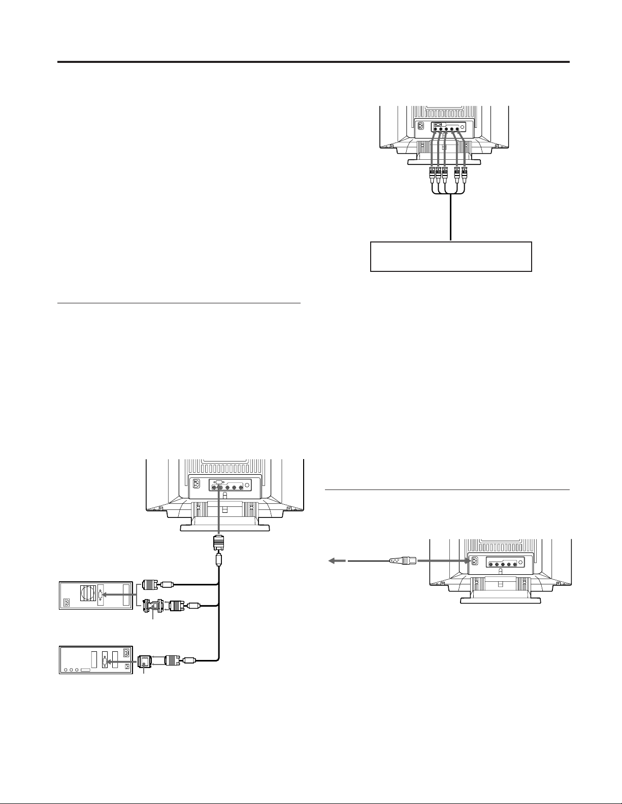
Step 1: Connect the monitor to the
computer.
With the computer switched off, connect the video signal
cable to the monitor (HD15/5 BNC’s) and connect the other
end to the video output.
To connect the HD15 connector, use the supplied video
signal cable.
To connect the 5 BNC’s connector, use the SMF-400 video
signal cable (not supplied).
Note
Do not touch the pins of the video signal cable.
Connecting to the HD15 connector
Connecting to the 5 BNC’s connector
to VIDEO IN R/G/B
Connect to the computer in the same
way as for the HD15 connector.
to SYNC IN HD/VD
Video signal cable SMF400 (not supplied)
For the customers using IBM PC or IBM compatible
system which is not compatible with DDC2AB and
DDC2B+
This monitor uses a No. 9 pin in the video signal connector for
DDC2AB and DDC2B+ compatibility.
Some PC systems which are not compatible with either DDC2AB or
DDC2B+ may not accept the No. 9 pin. If you are not sure whether
your PC system accepts the No. 9 pin or not, use the HD15 (Female)
- HD15 (Male without the No. 9 pin) adapter (supplied). Make sure
that the male side (without the No. 9 pin) is connected to the
computer.
For the customers using the Macintosh computer
Supplied Macintosh adapter is compatible with Macintosh LC,
Performa, Quadra and Power macintosh series computers.
Macintosh II series and some older version of PowerBook models
may need an adapter with micro switches.
to HD15
IBM or compatible
computer
Macintosh computer
* The HD15–HD15 adapter may be needed for some models.
to video output
Video signal
cable
(supplied)
HD15–HD15 adapter
(supplied) *
to video output
Macintosh adapter
(supplied)
Step 2: Connect the power cord.
With the monitor switched off, connect the power cord to
the monitor and the other end to the power outlet.
to a wall outlet
Power cord (supplied)
The installation of your monitor is complete. Enjoy your
monitor.
Notice
To comply with the limits of FCC class B and IC Class B for digital
device, please attach supplied video signal cable for HD15 input or
SMF-400 (not supplied) for BNC input. Furthermore, each cable
must have ferrite cores in it.
1) Macintosh and Power Macintosh are trademarks of Apple
Computer Inc.
2) VGA is a trademark of IBM Corporation.
4
Page 5
Preset Modes
Preset modes
The monitor has nine factory preset modes for true “Plug &
Play” capability.
Table of preset modes
No. Resolution Horizontal Vertical Graphic mode
(dots×lines) Frequency Frequency
1 640 × 480 31.5 kHz 60 Hz VGA Graphic
2 720 × 400 31.5 kHz 70 Hz VGA Text
3 1280 × 1024 80.0 kHz 75 Hz VESA
4 1600 × 1200 93.8 kHz 75 Hz VESA
5 1920 × 1080 67.5 kHz 60 Hz Sony
6 1920 × 1080 84.4 kHz 72 Hz Sony
7 1600 × 1024 81.3 kHz 76 Hz Sony
8 1920 × 1200 95.0 kHz 76 Hz Sony
9 1920 × 1035 33.8 kHz 60 Hz HDTV
1) VESA is a trademark of Video Electronics Standard Association.
1)
User modes
When using a video mode that is not one of the preset
modes, some fine tuning may be required to optimize the
display to your preference. Simply adjust the monitor
according to the adjustments instructions on pages 9 to 15.
The adjustments will be stored automatically and recalled
whenever that mode is used.
A total of 16 user-defined modes can be stored in memory.
If a 17th mode is entered, it will replace the first.
For less common modes, and modes that may evolve in the
future, the Digital Multiscan Technology of this monitor will
perform all of the complex adjustments necessary to ensure
a high quality picture for any timing in its frequency range.
However, due to the wide variety of video boards on the
market, it may be necessary for the user to fine tune the
vertical/horizontal size and centering.
Recommended horizontal timing conditions
Horizontal sync width should be more than 0.8 µsec.
Horizontal blanking width should be more than 2.7 µsec.
Note for Windows
Check your video board manual or the utility program
which comes with your graphic board and select the highest
available refresh rate to maximize monitor performance.
2) Windows is a registered trademark of Microsoft Corporation in
the United States and other countries.
® 2)
users
EN
F
D
Selecting the Input Signal
This monitor has two signal input connectors and can
connect two computers. When the power of both computers
is on, select the signal you want to input as follows.
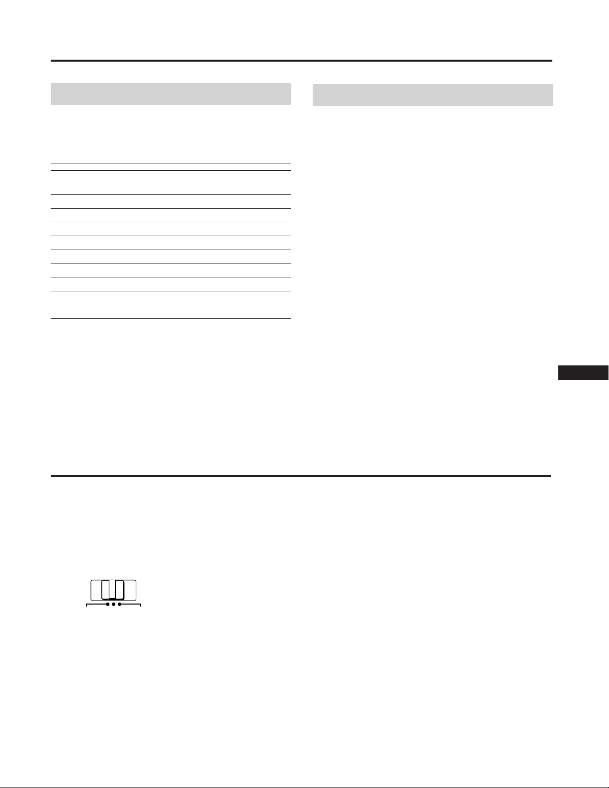
1 Turn on power of the monitor and the computer.
2 Select the input signal.
HD15
INPUT
To input the signal from the computer connected to
the 5 BNC’s connector
Set the INPUT switch to BNC.
To input the signal from the computer connected to
the HD15 connector
Set the INPUT switch to HD15.
If only one computer is connected or turned on
Set the INPUT switch to AUTO (center position). The
input signal is automatically selected.
AUTO
BNC
3 If necessary, adjust the user controls according to
your preference on pages 9 to 15.
When you set the INPUT switch to “AUTO”and
connect computers to both connectors
If you turn on or restart the computer you want to input a signal
from, or the computer is in power saving mode, the monitor may
automatically select another computer’s signal. This is because no
signal is input to the monitor at that moment. If this happens,
select the signal using the INPUT switch.
For the customers using the Windows95
Even if you select SONY for the maker on the device select screen,
the model name (GDM-W900) may not appear. In this case, select
the DDC standard monitor.
ES
I
J
5
Page 6
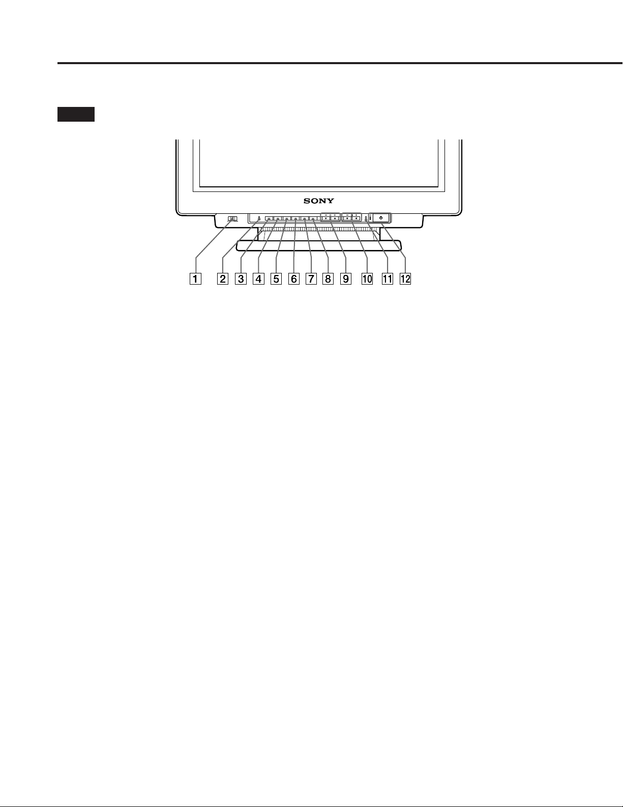
Functions of Controls
See the given pages for further description.
Front
1 INPUT switch (page 5)
Selects the input signal.
2 RESET button (page 12)
Resets the adjustment to the factory preset levels.
3 OPTION button (pages 8, 9, 13, 16)
Displays the “OPTION” OSD (On Screen Display).
4 COLOR button (pages 12, 15)
Displays the “COLOR” OSD to adjust color
temperature.
5 SCREEN button (pages 11, 14)
Displays the “SCREEN” OSD to adjust the vertical and
horizontal convergence, etc.
6 GEOM (geometry) button (pages 10, 14)
Displays the ”GEOMETRY” OSD to adjust the picture
rotation and pincushion, etc.
7 SIZE button (pages 10, 14)
Displays the “SIZE” OSD to adjust the picture size.
8 CENT (center) button (pages 10, 14)
Displays the “CENTER” OSD to adjust the picture
position.
0 > (contrast) −/+ (?//) buttons (pages 8 –
16)
Adjust the contrast.
Act as the −/+ (?//) buttons when adjusting other
items.
!¡ POWER SAVING indicator (page 17)
Lights up when the monitor is in the Power Saving
Mode.
!™ u power switch and indicator (page 17)
Turns the monitor on or off. The indicator lights up
when the monitor is turned on.
9 ¨ (brightness) −/+ (./>) buttons (pages 8
– 16)
Adjust the picture brightness.
Act as the –/+ (./>) buttons when adjusting other
items.
6
Page 7

Rear
OPT ION
LANGUAGE
OSD POS I TION:
OSD MENU
LOCK
I NPUT : BNC
JPN ENG FRA
DEU ESP I TA
RIGHT BOTTOM
NORMAL EXPERT
UNLOCK LOCK
84.4
kHz / 72Hz
SEL ECT
SET
OPTION OSD
1
(HD15)
(BNC)
R
2
B
HD VD
G
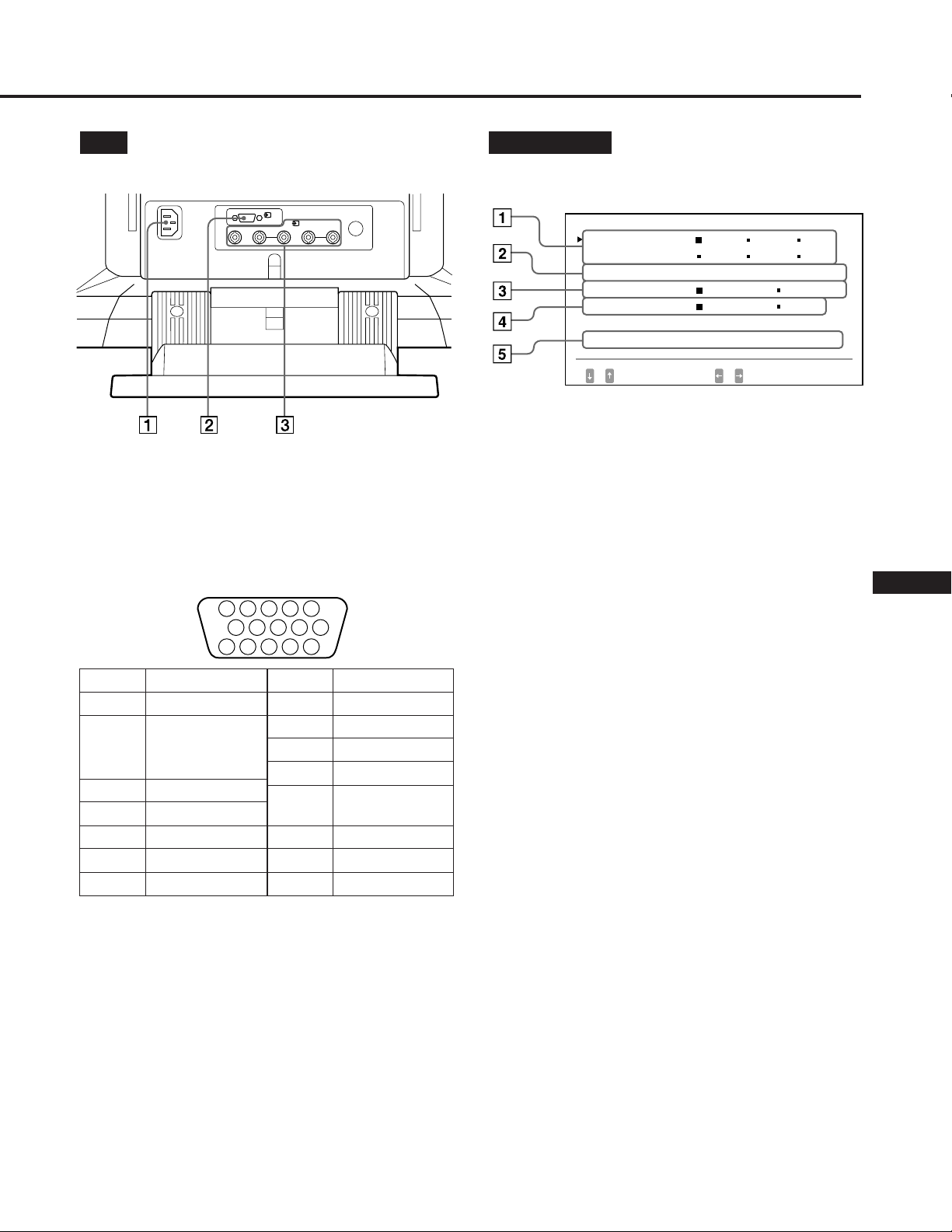
1 AC IN connector
Plug in an AC power cord.
2 Video input 1 connector (HD15)
Inputs RGB video signal (0.714 Vp-p, positive) and
SYNC signal.
5 4 3 2
Pin No.
1
2
3
4
5
6
7
* Display Data Channel (DDC) Standard by VESA
Signal
Red
Green
(Composite
Sync on Green)
Blue
Ground
DDC Ground*
Red Ground
Green Ground
1
1112131415
Pin No.
8
9
10
11
12
13
14
15
678910
Signal
Blue Ground
DDC + 5V*
Ground
Ground
Bi-Directional
Data (SDA)*
H. Sync
V. Sync
Data Clock(SCL)*
1 LANGUAGE (page 8)
Selects an OSD language, Japanese, English, French,
German, Spanish, or Italian.
2 OSD POSITION (page 8)
Changes the OSD position to be displayed.
3 OSD MENU (pages 9, 13)
Selects the adjustment mode, normal or expert.
4 LOCK (page 16)
Turns on or off the control lock function.
5 INPUT (pages 5, 18)
Shows the current active connector, the BNC connectors
or the HD15 connector, and the signal frequency.
EN
F
D
ES
I
J
3 Video input 2 connector (5 BNC)
Inputs RGB video signal (0.714 Vp-p, positive).
7
Page 8
Selecting the OSD
Language
Japanese, English, French, German, Spanish, or Italian
versions of OSD are available.
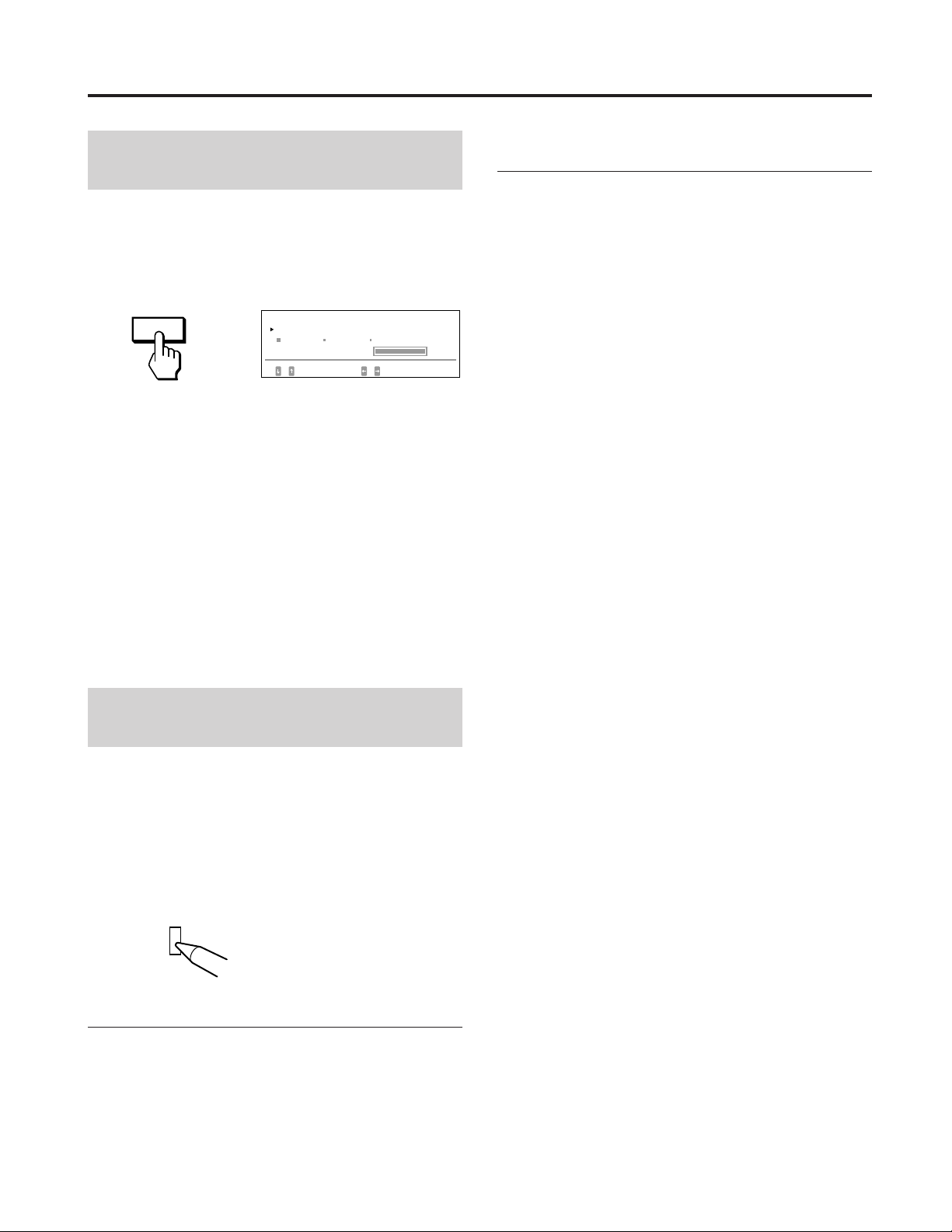
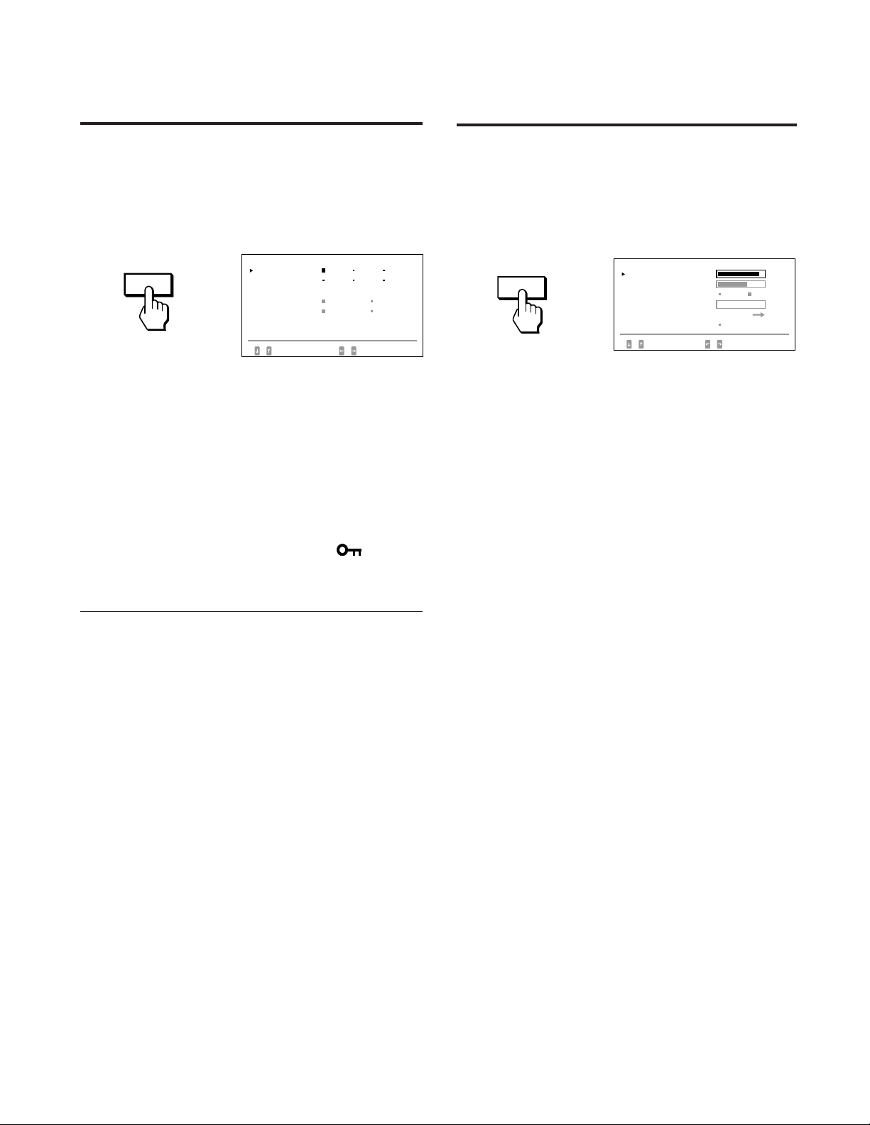
1 Press the OPTION button.
The “OPTION” OSD appears.
OPTION
2 Press the ¨./> button to select “LANGUAGE.”
3 Press the >?// button to move the OSD to the
desired position.
The “OPTION” OSD automatically disappears after about 30
seconds. To turn off the OSD, press the OPTION button
again.
OPT ION
LANGUAGE
OSD POS I TI ON:
OSD MENU
LOCK
I NPUT : BNC
SELECT
JPN ENG FRA
DEU ESP I TA
RIGHT BOTTOM
NORMAL EXPERT
UNLOCK LOCK
84.4
kHz/ 72Hz
SET
3 Press the >?// button to select the desired
language.
JPN: Japanese, ENG: English, FRA: French,
DEU: German, ESP: Spanish, ITA: Italian
The “OPTION” OSD automatically disappears after about
30 seconds. To turn off the OSD, press the OPTION button
again.
Changing the OSD
Operating the OSD
Select a parameter using the ¨./> buttons in the OSD
which parameters are arranged in vertical row, and adjust or
select the setting of the selected parameter using the
>?// buttons.
To select a parameter to adjust or select the setting,
press ¨. or > button.
The green ” mark goes to the selected parameter and the
parameter becomes yellow.
To adjust or select the settings of the selected parameter,
press >? or / button.
When adjusting, the bar length and the figure increase or
decrease.
When selecting the setting, the green p goes to the selected
setting.
Position
You can change the OSD position, for example, when you
want to adjust the picture behind the OSD.
1 Press the OPTION button.
The “OPTION” OSD appears.
2 Press the ¨./> button to select “OSD POSITION”.
OPT ION
8
LANGUAGE
OSD POS I T I ON :
OSD MENU
LOCK
I NPUT : BNC
SELECT
JPN ENG FRA
DEU ESP I TA
RIGHT BOTTOM
NORMAL EXPERT
UNLOCK LOCK
84.4
kHz/ 72Hz
SET
Page 9

Adjustments (Normal mode)
BRI GHTNESS / CON TRAST
23 10
BRI GHTNESS / CONTRAST
23 10
You can adjust the picture to your preference.
This monitor has two levels of adjustment mode, normal
and expert.
Before adjusting
• Connect the monitor and the computer, turn them on and
feed the signal to the monitor.
• Select “LANGUAGE” in the “OPTION” OSD, then select
“ENG” (English) on page 8.
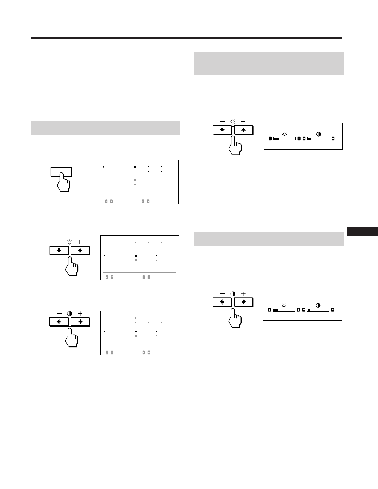
Selecting the normal mode
1 Press the OPTION button.
The “OPTION” OSD appears.
OPTION
2 Press the ¨./> button to select “OSD MENU.”
The “OSD MENU” becomes yellow.
OPT ION
LANGUAGE
OSD POS I T I ON :
OSD MENU
LOCK
I NPUT : BNC
SELECT
OPT ION
LANGUAGE
OSD POS I T I ON :
OSD MENU
LOCK
I NPUT : BNC
SELECT
JPN ENG FRA
DEU ESP I TA
RIGHT BOTTOM
NORMAL EXPERT
UNLOCK LOCK
84.4
kHz/ 72Hz
SET
JPN ENG FRA
DEU ESP I TA
RIGHT BOTTOM
NORMAL EXPERT
UNLOCK LOCK
84.4
kHz/ 72Hz
SET
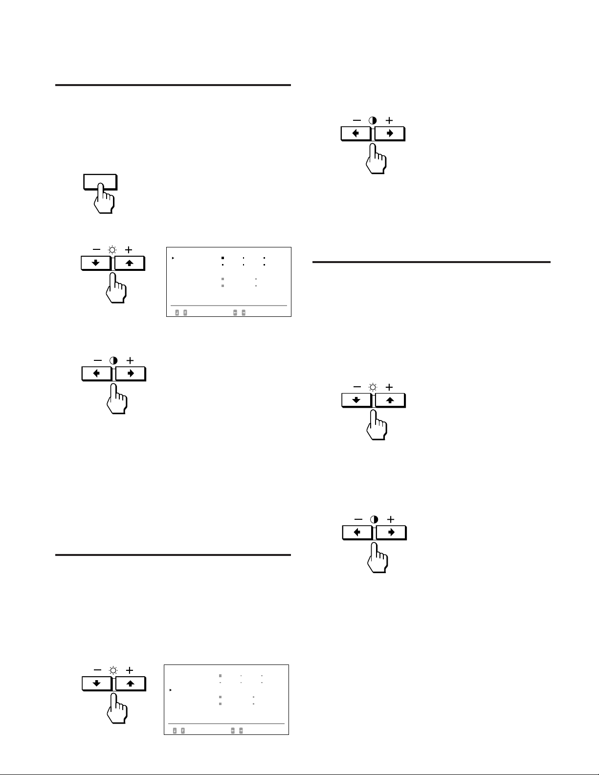
Adjusting the picture
brightness
The adjustment data becomes the common setting for all
input signals received.
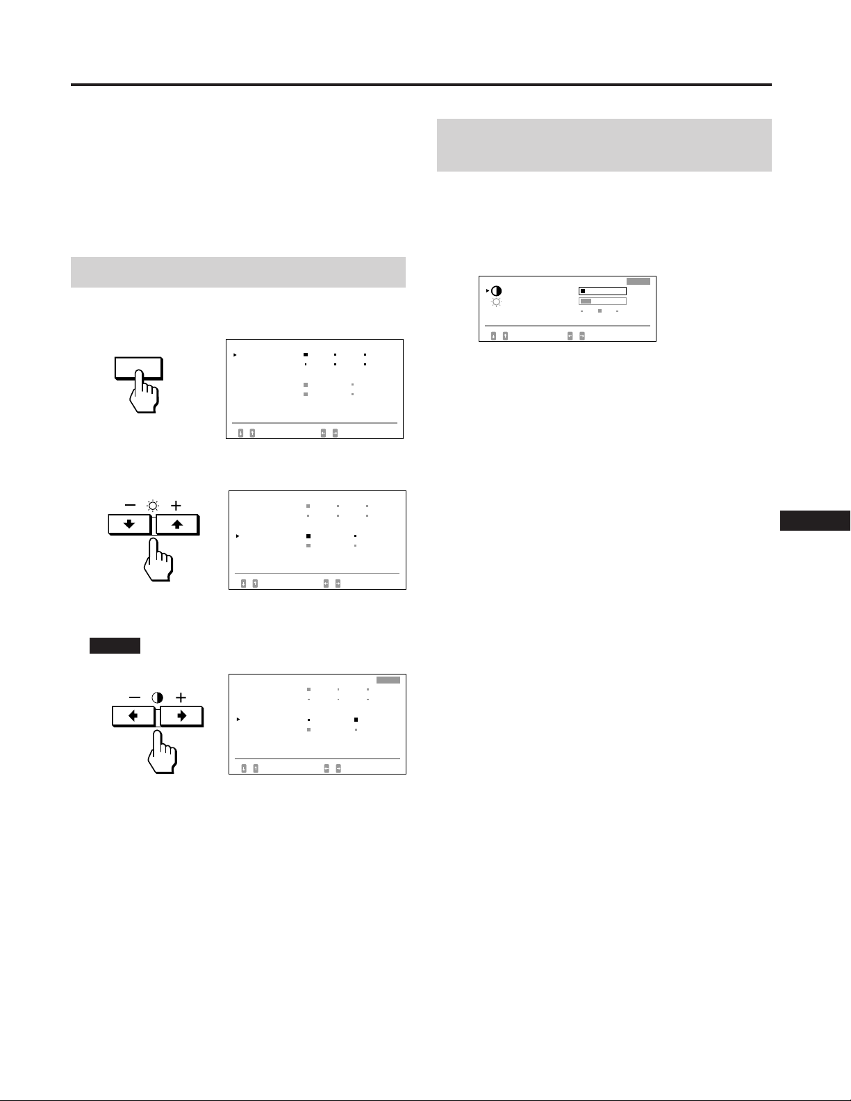
1 Press the¨ (brightness) ./> button.
The “BRIGHTNESS/CONTRAST” OSD appears.
2 Press the ¨./> button again to adjust picture
brightness.
. . . . for less brightness
> . . . for more brightness
The OSD automatically disappears after about 3 seconds.
To reset, press the RESET button while the OSD is on. The
brightness and contrast are both reset.
Adjusting the picture contrast
The adjustment data becomes the common setting for all
input signals received.
1 Press the > (contrast) ?// button.
The “BRIGHTNESS/CONTRAST” OSD appears.
EN
F
D
ES
3 Press the >?// button to select NORMAL.
Move the green p to NORMAL.
The “OPTION” OSD automatically disappears after about
30 seconds. To turn off the OSD, press the OPTION button
again.
OPT ION
LANGUAGE
OSD POS I T I ON :
OSD MENU
LOCK
I NPUT : BNC
SELECT
JPN ENG FRA
DEU ESP I TA
RIGHT BOTTOM
NORMAL EXPERT
UNLOCK LOCK
84.4
kHz/ 72Hz
SET
I
J
2 Press the >?// button again to adjust picture
contrast.
?. . . for less contrast
/ . . . for more contrast
The OSD automatically disappears after about 3 seconds.
To reset, press the RESET button while the OSD is on. The
brightness and contrast are both reset.
9
Page 10
Adjustments (Normal mode)
i
GEOMETRY
23 10
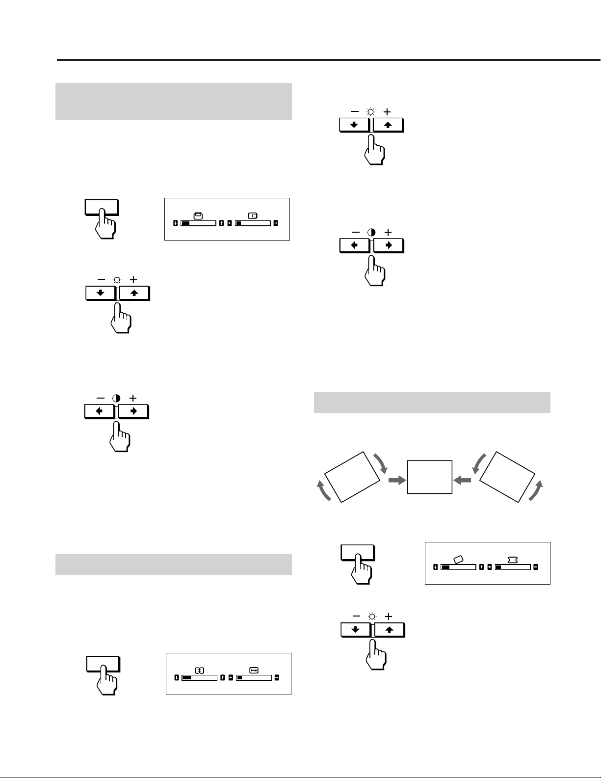
Adjusting the picture
centering
The adjustment data becomes the individual setting for each
input signal received.
1 Press the CENT button.
The “CENTER” OSD appears.
CENT
2 For vertical adjustment
Press the ¨ ./> buttons.
. . . . to move down
> . . . to move up
For horizontal adjustment
Press the > ?// buttons.
CENTER
23 10
2 For vertical adjustment
Press the ¨ ./> buttons.
. . . . to decrease
> . . . to increase
For horizontal adjustment
Press the > ?// buttons.
? . . . to decrease
/ . . . to increase
The OSD automatically disappears after about 10 seconds.
To turn off the OSD, press the SIZE button again.
To reset, press the RESET button while the OSD is on. The
horizontal and vertical sizes are both reset.
? . . . to move left
/ . . . to move right
The OSD automatically disappears after about 10 seconds.
To turn off the OSD, press the CENT button again.
To reset, press the RESET button while the OSD is on. The
horizontal and vertical centerings are both reset.
Adjusting the picture size
The adjustment data becomes the individual setting for each
input signal received.
1 Press the SIZE button.
The “SIZE” OSD appears.
SIZE
SIZE
23 10
Adjusting the picture rotation
The adjustment data becomes the common setting for all
input signals received.
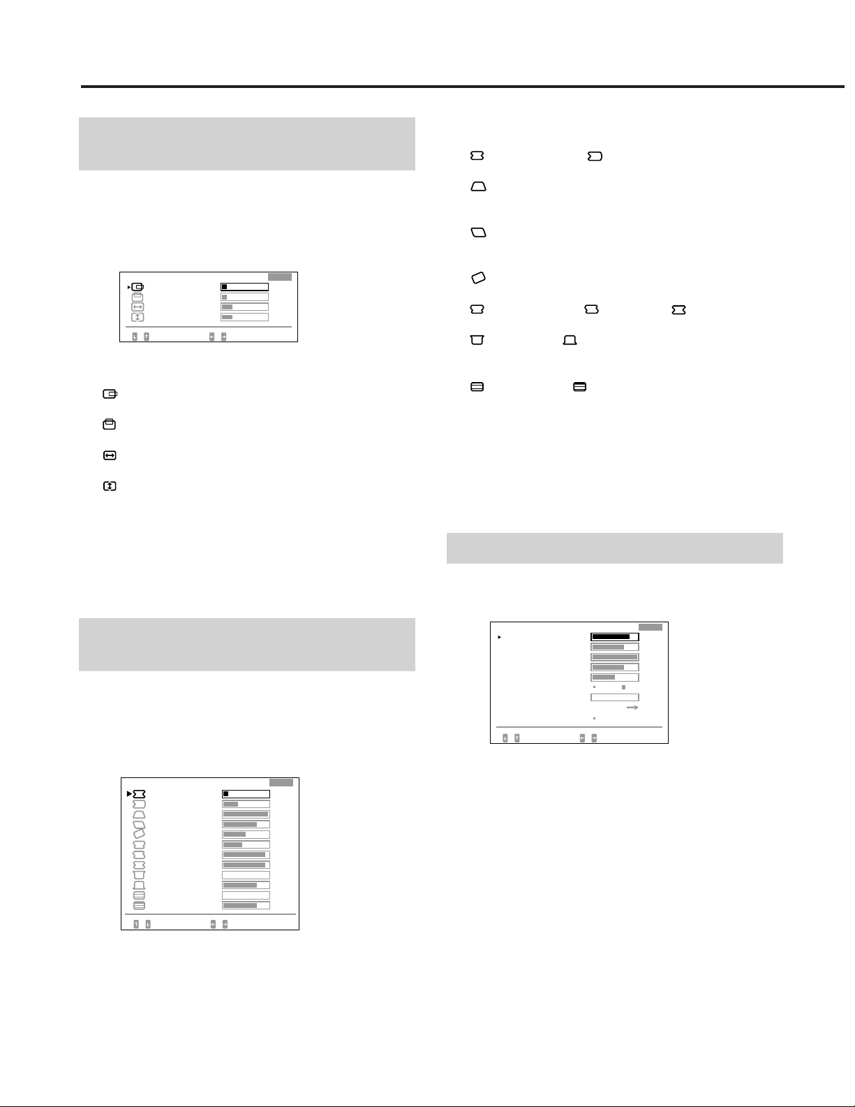
1 Press the GEOM button.
The “GEOMETRY” OSD appears.
GEOM
2 Press the ¨./> buttons.
. . . . to rotate counterclockwise
> . . . to rotate clockwise
10
The OSD automatically disappears after about 10 seconds.
To turn off the OSD, press the GEOM button again.
To reset, press the RESET button while the OSD is on. The
picture rotation and the pincushion settings are both reset.
Page 11
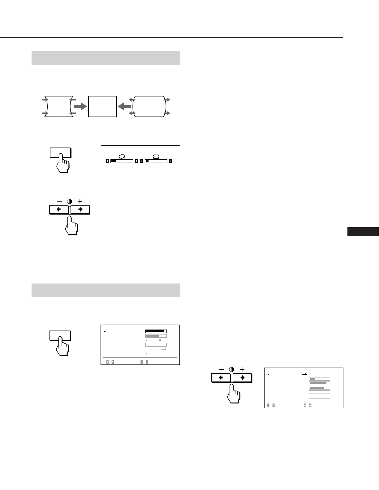
Adjusting the pincushion
The adjustment data becomes the individual setting for each
input signal received.
1 Press the GEOM button.
The “GEOMETRY” OSD appears.
GEOM
GEOMETRY
Convergence
The adjustment data becomes the common setting for all
input signals received.
Press the >?// button so that the red or blue
shadow disappears.
“H CONVERGENCE” (Horizontal convergence)
? . . . to move Red to the left and Blue to the right
/ . . . to move Red to the right and Blue to the left
“V CONVERGENCE” (Vertical convergence)
? . . . to move Red down and Blue up
/ . . . to move Red up and Blue down
23 10
2 Press the >?// button so that the picture edges
become straight.
The OSD automatically disappears after about 10 seconds.
To turn off the OSD, press the GEOM button again.
To reset, press the RESET button while the OSD is on. The
picture rotation and the pincushion settings are both reset.
Adjusting the screen
1 Press the SCREEN button.
The “SCREEN” OSD appears.
SCREEN
2 Press the ¨./> button to select the parameter you
want to adjust referring to the following.
The selected parameter turns yellow.
The OSD automatically disappears after about 30 seconds.
To turn off the OSD, press the SCREEN button again.
To reset, press the RESET button while the OSD is on. The
selected parameter is reset.
SCREEN
H CONVERGENCE
V CONVERGENCE
CANCEL MOIRE
MOI RE ADJ
LANDING
DEGAUSS
SELECT
OFF ON
ADJUST
ON
SET /AD JUST
85
72
Canceling the Moire
The adjustment data becomes the individual setting for each
input signal received.
Press the >?// button to select “ON” for “CANCEL
MOIRE.”
If the picture becomes unclear
The picure may become unclear by canceling moire.
1 Press the ¨./> button to select “MOIRE ADJ.”
2 Press the >?// button to adjust beginning from 0
until the moire is minimum.
EN
F
Landing
D
Correct when the color is not uniform due to influence from
the earth’s magnetizm.
The adjustment data becomes the common setting for all
input signals received.
First, degauss the screen, then display an entirely white
picture for more than 20 minutes before the adjustment to
adjust more accurately.
ES
I
J
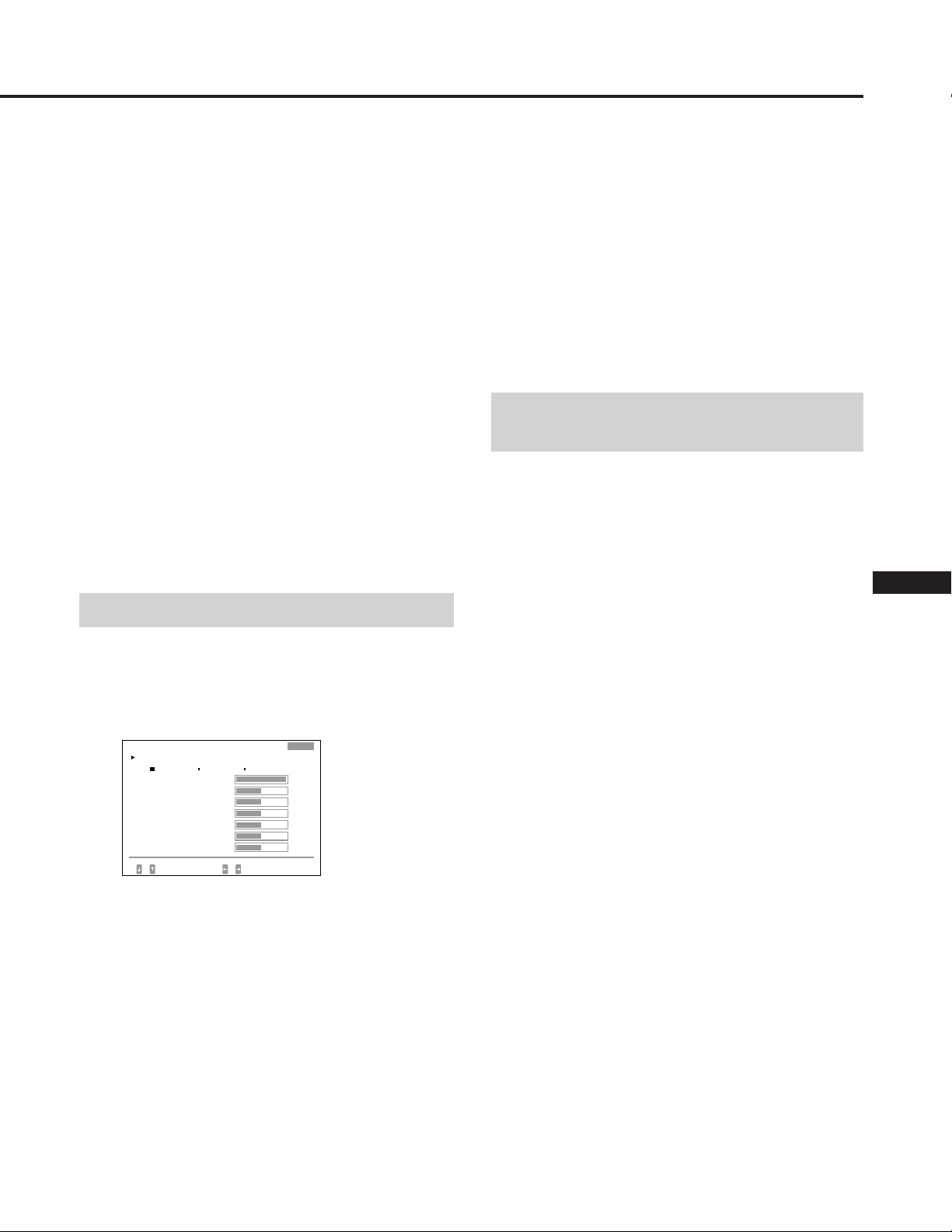
1 Press the ¨./> button to select “DEGAUSS.”
2 Press the >/ button.
0
The screen is degaussed for about five seconds.
3 Press the ¨./> button to select “LANDING.”
4 Press the >/ button.
The “LANDING” OSD appears on the screen.
LAND I NG
SCREEN MENU
CENTER TOP/ BOT
LEFT TOP
RIGHT TOP
RIGHT BOTTOM
LEFT BOTTOM
SELECT ADJUST
25
85
72
0
0
5 Press the ¨./> button to select the position, and
adjust by pressing the > ?// button.
To return to the “SCREEN” OSD, select “SCREEN MENU
/” and press the >/ button.
To reset, press the RESET button while the OSD is on. The
selected parameter is reset.
11
Page 12
Adjustments (Normal mode)
Adjusting the color
temperature
The adjustment data becomes the common setting for all
input signals received.
1 Press the COLOR button.
The “COLOR” OSD appears.
COLOR
2 Press the >?// buttons to select a color
temperature.
The factory settings are:
5000K, 6500K, 9300K
Adjusting the color temperature
Press the ¨./> button to select “VARIABLE,” and
adjust by pressing the >?// button.
The figure of the adjusted color temperature changes.
The OSD automatically disappears after about 30 seconds.
To turn off the OSD, press the COLOR button again.
COLOR
COLOR TEMPERATURE
5000K 6500K 9300K
VARIABLE
SELECT SET / ADJUST
Resetting the picture size, position,
moire, and geometry* at the same time
When there is no OSD displayed, press and hold the
RESET button for one second.
The above items of the current input signal are reset to
factory-preset levels.
* The ”Rotation” adjustment (pages 10, 14) is not reset.
To reset, press the RESET button while the OSD is on. The
selected color tempetarure is reset. The adjustments you
made in the expert mode (page 15) are also reset.
Resetting to the factorypreset levels
1 Press the button of the OSD you want to reset to the
factory setting.
2 When the parameters are arranged in vertical row in
the OSD, select a parameter you want to reset by
pressing the ¨./> buttons.
3 Press the RESET button.
RESET
Resetting all adjustment data
When there is no OSD displayed, press and hold the
RESET button for more than two seconds.
All adjustment data including the brightness and contrast
are reset to factory-preset levels.
12
Page 13
Adjustments (Expert mode)
You can adjust more in detail in the expert mode than in the
normal mode.
Before adjusting
• Connect the monitor and the computer, turn them on and
feed the signal to the monitor.
• Select “LANGUAGE” in the “OPTION” OSD, then select
“ENG” (English) on page 8.
Selecting the expert mode
1 Press the OPTION button.
The “OPTION” OSD appears.
OPTION
2 Press the ¨./> button to select “OSD MENU.”
The “OSD MENU” turns yellow.
3 Press the >?// button to select “EXPERT.”
Move the green p to EXPERT.
EXPERT appears at the top right corner of the OSD in
Expert mode.
OPT ION
LANGUAGE
OSD POS I T I ON :
OSD MENU
LOCK
I NPUT : BNC
SELECT
OPT ION
LANGUAGE
OSD POS I T I ON :
OSD MENU
LOCK
I NPUT : BNC
SELECT
OPT I ON
LANGUAGE
OSD POS I T I ON:
OSD MENU
LOCK
I NPUT : BNC
SELECT
JPN ENG FRA
DEU ESP I TA
RIGHT BOTTOM
NORMAL EXPERT
UNLOCK LOCK
84.4
kHz/ 72Hz
SET
JPN ENG FRA
DEU ESP I TA
RIGHT BOTTOM
NORMAL EXPERT
UNLOCK LOCK
84.4
kHz/ 72Hz
SET
EXPERT
ENGJPN FRA
ESP ITADEU
RIGHT
BOTTOM
NORMAL
84.4
EXPERT
LOCKUNLOCK
kHz/ 72Hz
SET /AD JUST
Adjusting the picture
brightness and contrast
The adjustment data becomes the common setting for all
input signals received.
1 Press the ¨./> button or the >?// button.
The “BRIGHTNESS/CONTRAST” OSD appears.
1
EXPERT
23
10
23
BRI GHTNESS / CONTRAST
CON TRAST
BRI GHTNESS
PRESET
SELECT SET / ADJUST
2 Press the ¨./> button to select “PRESET” and the
> ?// button to select a preset number.
When you want to use the monitor later in the same
condition, just select the same preset number.
3 Press the ¨./> button or the >?// button to
adjust the brightness or contrast.
¨ BRIGHTNESS:
Adjusts the picture brightness.
> CONTRAST:
Adjusts the picture contrast.
The OSD automatically disappears after about 30 seconds.
To turn off the OSD, press the ¨./> or >?// button
again.
To reset, press the RESET button while the OSD is on. The
selected preset number is reset.
EN
F
D
ES
I
J
The “OPTION” OSD automatically disappears after about
30 seconds. To turn off the OSD, press the OPTION button
again.
13
Page 14
Adjustments (Expert mode)
Adjusting the picture
centering and size
The adjustment data becomes the individual setting for each
input signal received.
1 Press the SIZE button or the CENT button.
The “CENTER/SIZE” OSD appears.
CENTER/ S I ZE
H CENTER
V CENTER
H S I ZE
V S I ZE
SELECT ADJUST
2 Press the ¨./> button to select and the > ?//
button to adjust the parameter.
H CENTER:
Adjusts the picture position in horizontal direction.
V CENTER:
Adjusts the picture position in vertical direction.
H SIZE:
Adjusts the picture size in horizontal direction.
V SIZE:
Adjusts the picture size in vertical direction.
The OSD automatically disappears after about 30 seconds.
To turn off the OSD, press the SIZE or CENT button again.
EXPERT
10
10
23
23
2 Press the ¨ ./> button to select and the > ?//
button to adjust the parameter.
H PINCUSHION/ H PIN BAL:
Corrects the picture distortion of the picture edges.
H KEYSTONE:
Corrects the difference of picture size at the top and
bottom.
H KEY BAL:
Corrects the imbalance of picture position at the top and
bottom.
ROTATION:
Corrects the picture rotation.
S PINCUSHION/ S PIN BAL/ C BOW:
Corrects the wavy distortion of the picture edges.
FLARE TOP/ FLARE BOT:
Corrects the flare distortion of the picture at the top and
bottom.
V LINEARITY/ V LIN BAL:
Corrects the vertical linearity and the vertical linearity
balance.
The OSD automatically disappears after about 30 seconds.
To turn off the OSD, press the GEOM button again.
To reset, press the RESET button while the OSD is on. The
selected parameter is reset.
Adjusting the screen
To reset, press the RESET button while the OSD is on. The
selected parameter is reset.
Adjusting the picture
rotation and the pincushion
The adjustment data becomes the individual setting for each
input signal received.
1 Press the GEOM button.
The “GEOMETRY” OSD appears.
GEOM ETRY
H P I NCUSH I ON
H P I N BAL
H KEYSTONE
H KEY BAL
ROTAT I ON
S P I NCUSH I ON
S P I N BAL
W
C BO
FLARE TOP
FLARE BOT
V L I NEAR I TY
V L I N BAL
SELECT ADJUST
EXPERT
10
33
100
75
50
42
93
93
0
75
0
75
1 Press the SCREEN button.
The “SCREEN” OSD appears.
SCREEN
H CONVERGENCE
V CONVERGENCE
V CONV TOP
V CONV BOT
H FOCUS
CANCEL MOI RE
MOI RE ADJ
LANDI NG
DEGAUSS
SELECT
OFF ON
ADJUST
ON
EXPERT
85
72
100
75
50
SET /AD JUST
0
2 Press the ¨./> button to select and the >?//
button to adjust the parameter.
H CONVERGENCE/V CONVERGENCE:
Adjusts the horizontal convergence and the vertical
convergence.
The adjustment data becomes the common setting for all
input signals received.
V CONV TOP/V CONV BOT:
Adjusts the vertical convergence at the top and bottom
of the screen.
The adjustment data becomes the common setting for all
input signals received.
14
H FOCUS:
Adjusts the horizontal focusing.
The adjustment data becomes the common setting for all
input signals received.
Page 15
CANCEL MOIRE:
Cancels the moire when ”ON” is selected.
The adjustment data becomes the individual setting for
each input signal received.
MOIRE ADJ:
Reduces fuzziress of the picture caused by canceling
moire.
Adjust beginning from 0 until the moire is minimum.
The adjustment data becomes the individual setting for
each input signal received.
LANDING:
See “Landing” on page 11.
The adjustment data becomes the common setting for all
input signals received.
DEGAUSS:
See “Degaussing the screen” on page 16.
The OSD automatically disappears after about 30 seconds.
To turn off the OSD, press the COLOR button again.
To reset all parameters of a particular color
temperature
Select the color temperature in step 2, and then press the
RESET button. All parameters of the color temperature are
reset and “++” at the right shoulder disappears.
To reset a particular parameter of a particular color
temperature
Select the parameter in step 3, and then press the RESET
button. Only the selected parameter of the color
temperature is reset.
Resetting to the factorypreset levels
The OSD automatically disappears after about 30 seconds.
To turn off the OSD, press the SCREEN button again.
To reset, press the RESET button while the OSD is on. The
selected parameter is reset.
Adjusting the color
The adjustment data becomes the common setting for all
input signals received.
1 Press the COLOR button.
The “COLOR” OSD appears.
COLOR
COLOR TEMPERATURE
5000K 6500K 93 00K
VARI ABLE
R B I AS
G B I AS
B B I AS
R GA I N
G GA I N
B GA I N
SELECT SET / ADJUST
2 Press the >?// button to select the color
temperature to adjust, 5000, 6500 or 9300.
EXPERT
100
50
50
50
50
50
50
Reset in the same way as described in “Resetting to the
factory-preset levels” on page 12.
EN
F
D
ES
I
J
3 Press the ¨./> button to select and the >?//
button to adjust the parameter.
VARIABLE:
Adjusts the color selected in step 2 to the desired color
temperature. The figure of the selected color
temperature changes.
R BIAS/G BIAS/B BIAS:
Adjusts the black level of each signal. “++” appears at
the right shoulder of the adjusted color temperature.
R GAIN/G GAIN/B GAIN:
Adjusts the white level of each signal. “++” appears at
the right shoulder of the adjusted color temperature.
15
Page 16
Control Lock
SCREEN
08
Degaussing the
Function
The control lock function disables all the buttons on the
front panel except the u (power) and OPTION buttons and
the INPUT switch.
1 Press the OPTION button.
The “OPTION” OSD appears.
OPTION
2 Press the ¨./> button to select “LOCK.”
3 Press the >?// button to select “LOCK.”
The “OPTION” OSD automatically disappears after about
30 seconds. To turn off the OSD, press the OPTION button
again.
Once you select “LOCK,” you cannot select other item on
the “OPTION” OSD using the ¨ ./> button.
If you press any button other than the u (power) and
OPTION buttons and the INPUT switch, the
appears on the screen.
OPT ION
LANGUAGE
OSD POS I T I ON :
OSD MENU
LOCK
I NPUT : BNC
SELECT
JPN ENG FRA
DEU ESP I TA
RIGHT BOTTOM
NORMAL EXPERT
UNLOCK LOCK
84.4
kHz/ 72Hz
SET
mark
Screen
The screen of the monitor is automatically degaussed when
the power is turned on (page 3).
You can degauss manually.
1 Press the SCREEN button.
The “SCREEN” OSD appears.
SCREEN
H CONVERGENCE
V CONVERGENCE
CANCEL MOIRE
MOI RE ADJ
LANDING
DEGAUSS
SELECT
OFF ON
ADJUST
ON
SET /AD JUST
2 Press the ¨ ./> button to select “DEGAUSS.”
3 Press the > / button.
The screen is degaussed for about five seconds.
85
72
0
To cancel the control lock
Press the > ?// button to select “UNLOCK.”
Note
Use the control lock function only when necessary.
16
Page 17
Plug & Play
This monitor complies with the DDC1, DDC2B and
DDC2AB which are the Display Data Channel (DDC)
standards of VESA.
When a DDC1 host system is connected, the monitor
synchronizes with the V. CLK in accordance with the VESA
standards and outputs the EDID (Extended Display
Identification Data) to the data line.
When a DDC2B or DDC2AB host system is connected, the
monitor automatically switches to each communication.
DDC is a trademark of Video Electronics Standard Association.
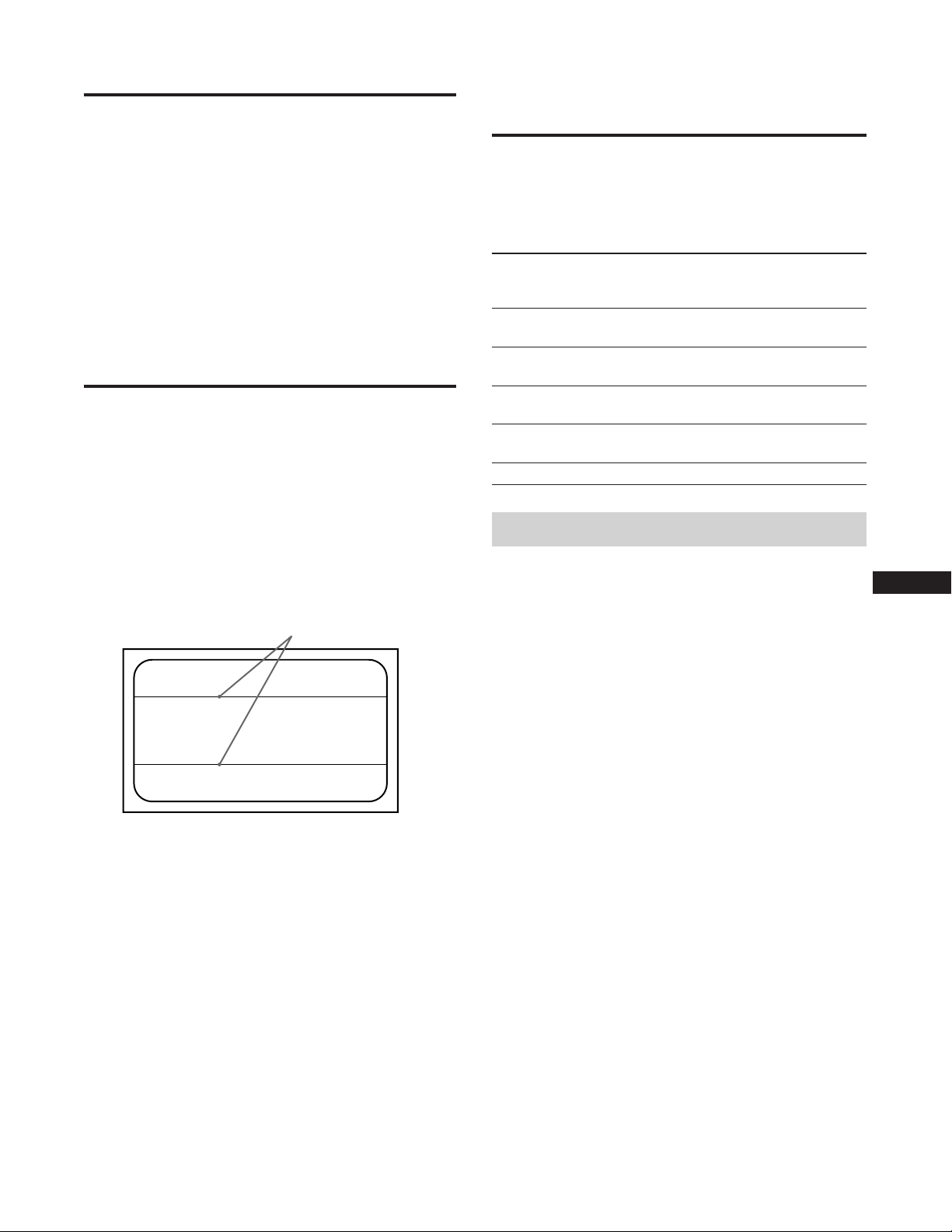
Damper Wire
Using a white background, very thin horizontal lines on the
screen are visible as shown below. These lines are damper
wires.
The Trinitron tube has a vertically striped Aperture Grill
inside. The Aperture Grille allows more light to pass
through to the screen giving the Trinitron CRT more color
and brightness.
These damper wires are attached to the Aperture Grille to
prevent vibration of the Aperture Grille wire so that the
screen image is constantly stable.
Power Saving
Function
This monitor is capable of three states of reduced power
consumption. By sensing the absence of video signals and
one or both sync signals coming from the host computer, it
will reduce power consumption as follows.
Power
consumption
state
Normal
1
operation
Standby
2
(1st state)
Suspend
3
(2nd state)
Active-off
4
(3rd state)
Power-off
5
Power
consumption
≤ 200 W
≤ 140 W
≤ 15 W
≤ 8 W
0 W
Recovery
time
—
Approx.
3 sec.
Approx.
3 sec.
Approx.
10 sec.
—
Power saving operation
• The H-sync is not present.
/ The unit goes into standby state.
POWER
SAVING
indicator
Off
Orange on
Orange on
Orange on
Off
u (power)
indicator
Green on
Green on
Green on
Off
Off
EN
Damper wire
• The V-sync is not present.
/ The unit goes into suspend state.
• Both the H-sync and V-sync are not present.
/ The unit goes into active-off state.
The monitor requires a video card or screen saver software
which switches off one or both sync signals to activate the
power saving function.
Caution
If no video signal is input to the monitor, or if the INPUT
switch is set to the connector to which no signal is input
when you turn on the monitor, the input signal warning
indicator (page 18) appears. After 30 seconds, the Power
Saving function automatically puts the monitor into the
Active-off state and the POWER SAVING indicator lights
up. Once the horizontal and vertical syncs are sensed, the
monitor will automatically return to its Normal operation
state.
F
D
ES
I
J
17
Page 18
Input Signal
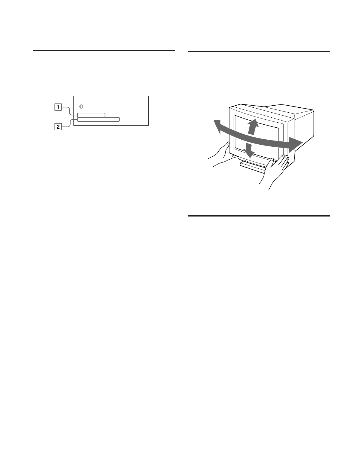
Use of the Tilt-
Warning Function
If there is something wrong with the input signal, one of the
following messages appears when you turn the monitor off
and on, or when you operate the INPUT switch.
The message disappears after about 30 seconds.
PLEASE CHECK THE S I GNAL
INPUT : HD15
FH : 84.4kHz
1 Shows the INPUT switch setting.
2 Shows the input signal condition.
“FH: - kHz” indicates no horizontal sync signal.
“FV: - Hz” indicates no vertical sync signal.
“OUT OF SCAN RANGE” indicates that the input signal
is not supported by the monitor’s specifications.
“NO CONNECTION” indicates that the supplied video
signal cable is disconnected from the HD15 connector
when the INPUT switch is set to “HD15.”
FV: _ Hz
Swivel
With the tilt-swivel, this unit can be adjusted to be viewed
at the desired angle within 310° horizontally and 20°
vertically.
To turn the unit vertically and horizontally, hold it at its
bottom with both hands as illustrated below.
155°
15°
155°
5°
Specifications
Picture tube 0.25 – 0.28 mm aperture grille pitch
24 inches measured diagonally
90-degree deflection
Viewable image size Approx. 482 × 304 mm (w/h)
(19 × 12 inches)
22.5” viewing image
Resolution Horizontal: Max. 1920 dots
Vertical: Max. 1200 lines
Standard image area Approx. 473 × 296 mm (w/h)
Deflection frequency Horizontal: 30 to 96 kHz
Input HD15 (1), 5 BNC (1)
AC input voltage/current
Power consumption Max. 200 W
Dimensions 580 × 500 × 548 mm (w/h/d)
Mass Approx. 41 kg (90 lb 6 oz)
5
(18
/8 × 11 3/4 inches)
Vertical: 50 to 160 Hz
R/G/B: 75 Ω, 0.714 Vp-p, positive
HD/VD or Composite sync
Sync-on-green: 0.286 Vp-p,
negative
100 to 120 V, 50/60 Hz, 2.2 A
200 to 240 V, 50 – 60 Hz, 1.4 A
7
(22
/8 × 19 3/4 × 21 5/8 inches)
18
Design and specifications are subject to change without
notice.
Page 19

Troubleshooting
This section may help you isolate a problem and as a result, eliminate the need to contact technical support, allowing
continued productivity.
Note the model name and the serial number of your monitor. Also note the make and name of your computer and video
board.
Symptom Check these items
No picture
If neither u (power)
indicator nor POWER
SAVING indicator is lit
If the POWER SAVING
indicator is lit
If the u (power) indicator
is flashing in green
If the u (power) and/or
POWER SAVING
indicators are flashing in
orange
If you do the above
procedures and the
monitor does not recover
If using a Macintosh
system
If using a Windows95
• Check that the power cord is properly connected.
• Check that the u (power) switch is in the “on” position.
• Check that your computer power switch is in the “on” position.
• The monitor will recover when you press any key on the keyboard of the computer.
• The INPUT switch setting is incorrect.
• Check that the video signal cable is properly connected and all plugs are firmly seated in
their socket.
• Check that the 5 BNC’s are connected in the correct order (from the power cord side:
Red–Green–Blue–HD–VD).
• Ensure that no pins are bent or pushed in the HD15 video input connector.
• Check that the video board is seated completely in the proper bus slot.
• Check that the video frequency range is within that specified for the monitor.
(Horizontal: 30 – 96 kHz, Vertical: 50 – 160 Hz)
• Turn the monitor off and on. If the indicator is off, the monitor is in the normal
condition. If the indicator is still flashing, there is a potential monitor failure.
• Unplug the video input 1 and 2 connectors and wait for 5 seconds. Then press and hold
the > + button for 2 seconds to display the color bars. If the color bars appear, the
monitor may be in normal condition. Turn the monitor off and on to return to the
normal operation mode. If the color bars do not appear, there is a potential monitor
failure.
• Check that the Macintosh adapter and the video signal cable are properly connected,
and the dip switches of the adapter are properly set.
• When you cannot find “GDM-W900” among the Sony monitors on the Windows95
device select screen, select the DDC standard monitor.
EN
F
D
ES
I
J
Picture is scrambled
Color is not uniform
You cannot adjust the
monitor with the buttons on
the front panel
White does not look white
• Check your graphic board manual for proper monitor setting.
• Check this manual and confirm that the graphic mode and the frequency at which you
are trying to operate is supported (page 5). Even within the proper range some video
boards may have a sync pulse that is too narrow for the monitor to sync correctly.
• Degauss the monitor (page 16).
If you place equipment which generates a magnetic field such as a loudspeaker, or you
change the direction of the monitor, color may lose uniformity.
This function is to demagnetize the metal frame of the CRT to obtain a neutral field for
uniform color reproduction. If a second degauss cycle is needed, allow a minimum
interval of 20 minutes for the best result.
• Adjust the landing (page 11).
• If the control lock function is set to on, set it to off on the OPTION OSD (page 16).
You will be able to adjust the monitor.
• Adjust color (page 12, 15).
• Check that the 5 BNC’s are connected in the correct order (from the power cord side:
Red–Green–Blue–HD–VD).
Continued to the next page
19
Page 20

Troubleshooting
Symptom Check these items
Screen image is not centered
or sized properly
• Adjust the centering or size (pages 10, 14).
• Some video modes do not fill the screen to the edge of the monitor. There is no single
answer to solve the problem. This problem tends to occur on higher refresh timings.
Edges of the image are
curved
White lines show red or blue
shades at edges
Picture is fuzzy
Picture bounces or has wavy
oscillations
Picture is not stable
• Adjust the geometry items such as pincushion and keystone distortion (page 11, 14).
• Adjust the convergence (pages 11, 14).
• Adjust the contrast and brightness (page 9).
• Degauss the monitor (page 16).
If you place equipment which generates a magnetic field such as a loudspeaker, or you
change the direction of the monitor, color may lose uniformity.
This function is to demagnetize the metal frame of the CRT to obtain a neutral field for
uniform color reproduction. If a second degauss cycle is needed, allow a minimum
interval of 20 minutes for the best result.
• If red or blue shades are found at the edge of images, adjust the convergence (pages 11,
14).
• If the moire is cancelled, the picture may become fuzzy. Adjust so that the picture is as
clear as possible (page 11, 15).
• Isolate and eliminate any potential sources of electric or magnetic fields. Common causes
for this symptom are electric fans, fluorescent lighting, laser printers, and so on.
• If you have another monitor close to this monitor, increase the distance between them to
reduce the interference.
• Try plugging the monitor into a different AC outlet, preferably on a different circuit.
• Try the monitor on a completely different computer in a different room.
• Set the refresh rate to non-interlace of 75 Hz or more on the computer referring to the
computer’s manual.
Picture appears to be
ghosting
Two fine horizontal lines
(wires) are visible
Wavy or elliptical (moire)
pattern is visible
Hum is heard right after the
power is turned on
Because of vibration and
shock during transportation,
the Aperture Grille may
occasionally slip out of place
and black stripes may
appear
• Eliminate the use of video cable extension cable and/or video switch boxes if this
symptom occurs. Excessive cable length or weak connection can produce this symptom.
• These wires stabilize the vertically striped Aperture Grille (page 17). This Aperture Grille
allows more light to pass through to the screen giving the Trinitron CRT more color and
brightness.
• Cancel the moire (page 11, 15).
The moire may be modified depending on the connected computer.
• Due to the relationship between resolution, monitor dot pitch and the pitch of some
image patterns, certain screen backgrounds, especially gray, sometimes show moire.
Change your desktop pattern.
• When the power is turned on, the auto-degauss cycle is activated. While the Autodegauss cycle is activated, a hum may be heard. This is not a malfunction.
• Lightly pat the sides of the monitor.
20
Page 21

Table of Contents
Introduction .......................................................................... 3
Precautions ............................................................................ 3
Connections ........................................................................... 4
Preset Modes ......................................................................... 5
Selecting the Input Signal.................................................... 5
Functions of Controls........................................................... 6
Selecting the OSD Language .............................................. 8
Changing the OSD Position ................................................ 8
Operating the OSD ............................................................... 8
Adjustments (Normal mode).............................................. 9
Introduction
Congratulations on your purchase of a Sony Multiscan
series monitor.
This monitor incorporates over 25 years of Sony experience
with Trinitron
performance and outstanding reliability.
The advanced design of this monitor together with Digital
Multiscan Technology allows it to sync to any video mode
within its wide scan range.
®
display technology, ensuring excellent
Adjustments (Expert mode).............................................. 13
Control Lock Function ....................................................... 16
Degaussing the Screen ....................................................... 16
Plug & Play.......................................................................... 17
Damper Wire....................................................................... 17
Power Saving Function...................................................... 17
Input Signal Warning Function........................................ 18
Use of the Tilt-Swivel......................................................... 18
Specifications ...................................................................... 18
Troubleshooting ................................................................. 19
In addition, its four factory preset color modes and user
adjustable color modes give you unprecedented flexibility
in matching on-screen colors to hard copy printouts.
Furthermore, this monitor features digital control with OSD
(On Screen Display). It delivers easier adjustment by
visualizing your control statement. All together, it delivers
incredible performance with the quality and support you
can expect from Sony.
Trinitron® is a trademark of Sony Corporation.
EN
Precautions
Installation
• Prevent internal heat build-up by allowing adequate air
circulation. Do not place the unit on surfaces (rugs,
blankets, etc.) or near materials (curtains, draperies) that
may block the ventilation holes.
• Do not install the unit near heat sources such as radiators
or air ducts, or in a place subject to direct sunlight,
excessive dust, mechanical vibration or shock.
• Do not place the unit near equipment which generates
magnetism, such as a converter or high voltage power
lines.
Maintenance
• Clean the cabinet, panel and controls with a soft cloth
lightly moistened with a mild detergent solution. Do not
use any type of abrasive pad, scouring powder or solvent,
such as alcohol or benzine.
• Do not rub, touch, or tap the surface of the screen with
sharp or abrasive items, like a ballpoint pen or a
screwdriver. This type of contact may result in a scratched
picture tube.
Warning on power
connection
• Use the supplied power cord.
For the customers in UK
If you use the monitor in UK, please use the UK cable with
UK plug (not supplied).
• Before disconnecting the power cord, wait for at least 30
seconds after turning off the power to allow the static
electricity on the CRT display surface to discharge.
• After the power has been turned on, the CRT is
demagnetized for approximately five seconds. This
generates a strong magnetic field around the bezel, which
may affect the data stored on magnetic tapes or disks near
the bezel. Place such magnetic recording equipment and
tapes/disks away from this unit.
The socket-outlet should be installed near the
equipment and be easily accessible.
F
D
ES
I
J
Transportation
When you transport this monitor for repairing or shipping,
use the original carton box and packing materials.
3
Page 22

Connections
Before using this monitor, check that the following items
are included in your package:
• Monitor (1)
• Video signal cable (1)
• Power cord (1)
• Macintosh
1)
adapter (1)
• HD15 (Female) –HD15 (Male without the No. 9 pin)
adapter (1)
• Warranty card (1)
• This operating instructions (1)
This monitor will sync with any IBM or compatible system
equipped with VGA
2)
or greater graphics capability.
Although this monitor will sync with other platforms, a
cable adapter is required. Please consult your dealer for
advice on which adapter is suitable for your needs.
Step 1: Connect the monitor to the
computer.
With the computer switched off, connect the video signal
cable to the monitor (HD15/5 BNC’s) and connect the other
end to the video output.
To connect the HD15 connector, use the supplied video
signal cable.
To connect the 5 BNC’s connector, use the SMF-400 video
signal cable (not supplied).
Note
Do not touch the pins of the video signal cable.
Connecting to the HD15 connector
Connecting to the 5 BNC’s connector
to VIDEO IN R/G/B
Connect to the computer in the same
way as for the HD15 connector.
to SYNC IN HD/VD
Video signal cable SMF400 (not supplied)
For the customers using IBM PC or IBM compatible
system which is not compatible with DDC2AB and
DDC2B+
This monitor uses a No. 9 pin in the video signal connector for
DDC2AB and DDC2B+ compatibility.
Some PC systems which are not compatible with either DDC2AB or
DDC2B+ may not accept the No. 9 pin. If you are not sure whether
your PC system accepts the No. 9 pin or not, use the HD15 (Female)
- HD15 (Male without the No. 9 pin) adapter (supplied). Make sure
that the male side (without the No. 9 pin) is connected to the
computer.
For the customers using the Macintosh computer
Supplied Macintosh adapter is compatible with Macintosh LC,
Performa, Quadra and Power macintosh series computers.
Macintosh II series and some older version of PowerBook models
may need an adapter with micro switches.
to HD15
IBM or compatible
computer
Macintosh computer
* The HD15–HD15 adapter may be needed for some models.
to video output
Video signal
cable
(supplied)
HD15–HD15 adapter
(supplied) *
to video output
Macintosh adapter
(supplied)
Step 2: Connect the power cord.
With the monitor switched off, connect the power cord to
the monitor and the other end to the power outlet.
to a wall outlet
Power cord (supplied)
The installation of your monitor is complete. Enjoy your
monitor.
Notice
To comply with the limits of FCC class B and IC Class B for digital
device, please attach supplied video signal cable for HD15 input or
SMF-400 (not supplied) for BNC input. Furthermore, each cable
must have ferrite cores in it.
1) Macintosh and Power Macintosh are trademarks of Apple
Computer Inc.
2) VGA is a trademark of IBM Corporation.
4
Page 23

Preset Modes
Preset modes
The monitor has nine factory preset modes for true “Plug &
Play” capability.
Table of preset modes
No. Resolution Horizontal Vertical Graphic mode
(dots×lines) Frequency Frequency
1 640 × 480 31.5 kHz 60 Hz VGA Graphic
2 720 × 400 31.5 kHz 70 Hz VGA Text
3 1280 × 1024 80.0 kHz 75 Hz VESA
4 1600 × 1200 93.8 kHz 75 Hz VESA
5 1920 × 1080 67.5 kHz 60 Hz Sony
6 1920 × 1080 84.4 kHz 72 Hz Sony
7 1600 × 1024 81.3 kHz 76 Hz Sony
8 1920 × 1200 95.0 kHz 76 Hz Sony
9 1920 × 1035 33.8 kHz 60 Hz HDTV
1) VESA is a trademark of Video Electronics Standard Association.
1)
User modes
When using a video mode that is not one of the preset
modes, some fine tuning may be required to optimize the
display to your preference. Simply adjust the monitor
according to the adjustments instructions on pages 9 to 15.
The adjustments will be stored automatically and recalled
whenever that mode is used.
A total of 16 user-defined modes can be stored in memory.
If a 17th mode is entered, it will replace the first.
For less common modes, and modes that may evolve in the
future, the Digital Multiscan Technology of this monitor will
perform all of the complex adjustments necessary to ensure
a high quality picture for any timing in its frequency range.
However, due to the wide variety of video boards on the
market, it may be necessary for the user to fine tune the
vertical/horizontal size and centering.
Recommended horizontal timing conditions
Horizontal sync width should be more than 0.8 µsec.
Horizontal blanking width should be more than 2.7 µsec.
Note for Windows
Check your video board manual or the utility program
which comes with your graphic board and select the highest
available refresh rate to maximize monitor performance.
2) Windows is a registered trademark of Microsoft Corporation in
the United States and other countries.
® 2)
users
EN
F
D
Selecting the Input Signal
This monitor has two signal input connectors and can
connect two computers. When the power of both computers
is on, select the signal you want to input as follows.
1 Turn on power of the monitor and the computer.
2 Select the input signal.
HD15
INPUT
To input the signal from the computer connected to
the 5 BNC’s connector
Set the INPUT switch to BNC.
To input the signal from the computer connected to
the HD15 connector
Set the INPUT switch to HD15.
If only one computer is connected or turned on
Set the INPUT switch to AUTO (center position). The
input signal is automatically selected.
AUTO
BNC
3 If necessary, adjust the user controls according to
your preference on pages 9 to 15.
When you set the INPUT switch to “AUTO”and
connect computers to both connectors
If you turn on or restart the computer you want to input a signal
from, or the computer is in power saving mode, the monitor may
automatically select another computer’s signal. This is because no
signal is input to the monitor at that moment. If this happens,
select the signal using the INPUT switch.
For the customers using the Windows95
Even if you select SONY for the maker on the device select screen,
the model name (GDM-W900) may not appear. In this case, select
the DDC standard monitor.
ES
I
J
5
Page 24

Functions of Controls
See the given pages for further description.
Front
1 INPUT switch (page 5)
Selects the input signal.
2 RESET button (page 12)
Resets the adjustment to the factory preset levels.
3 OPTION button (pages 8, 9, 13, 16)
Displays the “OPTION” OSD (On Screen Display).
4 COLOR button (pages 12, 15)
Displays the “COLOR” OSD to adjust color
temperature.
5 SCREEN button (pages 11, 14)
Displays the “SCREEN” OSD to adjust the vertical and
horizontal convergence, etc.
6 GEOM (geometry) button (pages 10, 14)
Displays the ”GEOMETRY” OSD to adjust the picture
rotation and pincushion, etc.
7 SIZE button (pages 10, 14)
Displays the “SIZE” OSD to adjust the picture size.
8 CENT (center) button (pages 10, 14)
Displays the “CENTER” OSD to adjust the picture
position.
0 > (contrast) −/+ (?//) buttons (pages 8 –
16)
Adjust the contrast.
Act as the −/+ (?//) buttons when adjusting other
items.
!¡ POWER SAVING indicator (page 17)
Lights up when the monitor is in the Power Saving
Mode.
!™ u power switch and indicator (page 17)
Turns the monitor on or off. The indicator lights up
when the monitor is turned on.
9 ¨ (brightness) −/+ (./>) buttons (pages 8
– 16)
Adjust the picture brightness.
Act as the –/+ (./>) buttons when adjusting other
items.
6
Page 25
Rear
OPT ION
LANGUAGE
OSD POS I T ION:
OSD MENU
LOCK
I NPUT : BNC
JPN ENG FRA
DEU ESP I TA
RIGHT BOTTOM
NORMAL EXPERT
UNLOCK LOCK
84.4
kHz / 72Hz
SEL ECT
SET
OPTION OSD
1
(HD15)
(BNC)
R
2
B
HD VD
G
1 AC IN connector
Plug in an AC power cord.
2 Video input 1 connector (HD15)
Inputs RGB video signal (0.714 Vp-p, positive) and
SYNC signal.
5 4 3 2
Pin No.
1
2
3
4
5
6
7
* Display Data Channel (DDC) Standard by VESA
Signal
Red
Green
(Composite
Sync on Green)
Blue
Ground
DDC Ground*
Red Ground
Green Ground
1
1112131415
Pin No.
8
9
10
11
12
13
14
15
678910
Signal
Blue Ground
DDC + 5V*
Ground
Ground
Bi-Directional
Data (SDA)*
H. Sync
V. Sync
Data Clock(SCL)*
1 LANGUAGE (page 8)
Selects an OSD language, Japanese, English, French,
German, Spanish, or Italian.
2 OSD POSITION (page 8)
Changes the OSD position to be displayed.
3 OSD MENU (pages 9, 13)
Selects the adjustment mode, normal or expert.
4 LOCK (page 16)
Turns on or off the control lock function.
5 INPUT (pages 5, 18)
Shows the current active connector, the BNC connectors
or the HD15 connector, and the signal frequency.
EN
F
D
ES
I
J
3 Video input 2 connector (5 BNC)
Inputs RGB video signal (0.714 Vp-p, positive).
7
Page 26

Selecting the OSD
Language
Japanese, English, French, German, Spanish, or Italian
versions of OSD are available.
1 Press the OPTION button.
The “OPTION” OSD appears.
OPTION
2 Press the ¨./> button to select “LANGUAGE.”
3 Press the >?// button to move the OSD to the
desired position.
The “OPTION” OSD automatically disappears after about 30
seconds. To turn off the OSD, press the OPTION button
again.
OPT ION
LANGUAGE
OSD POS I T I ON :
OSD MENU
LOCK
I NPUT : BNC
SELECT
JPN ENG FRA
DEU ESP I TA
RIGHT BOTTOM
NORMAL EXPERT
UNLOCK LOCK
84.4
kHz/ 72Hz
SET
3 Press the >?// button to select the desired
language.
JPN: Japanese, ENG: English, FRA: French,
DEU: German, ESP: Spanish, ITA: Italian
The “OPTION” OSD automatically disappears after about
30 seconds. To turn off the OSD, press the OPTION button
again.
Changing the OSD
Operating the OSD
Select a parameter using the ¨./> buttons in the OSD
which parameters are arranged in vertical row, and adjust or
select the setting of the selected parameter using the
>?// buttons.
To select a parameter to adjust or select the setting,
press ¨. or > button.
The green ” mark goes to the selected parameter and the
parameter becomes yellow.
To adjust or select the settings of the selected parameter,
press >? or / button.
When adjusting, the bar length and the figure increase or
decrease.
When selecting the setting, the green p goes to the selected
setting.
Position
You can change the OSD position, for example, when you
want to adjust the picture behind the OSD.
1 Press the OPTION button.
The “OPTION” OSD appears.
2 Press the ¨./> button to select “OSD POSITION”.
OPT ION
8
LANGUAGE
OSD POS I T I ON :
OSD MENU
LOCK
I NPUT : BNC
SELECT
JPN ENG FRA
DEU ESP I TA
RIGHT BOTTOM
NORMAL EXPERT
UNLOCK LOCK
84.4
kHz/ 72Hz
SET
Page 27
Adjustments (Normal mode)
BRI GHTNESS / CON TRAST
23 10
BRI GHTNESS / CONTRAST
23 10
You can adjust the picture to your preference.
This monitor has two levels of adjustment mode, normal
and expert.
Before adjusting
• Connect the monitor and the computer, turn them on and
feed the signal to the monitor.
• Select “LANGUAGE” in the “OPTION” OSD, then select
“ENG” (English) on page 8.
Selecting the normal mode
1 Press the OPTION button.
The “OPTION” OSD appears.
OPTION
2 Press the ¨./> button to select “OSD MENU.”
The “OSD MENU” becomes yellow.
OPT ION
LANGUAGE
OSD POS I T I ON :
OSD MENU
LOCK
I NPUT : BNC
SELECT
OPT ION
LANGUAGE
OSD POS I T I ON :
OSD MENU
LOCK
I NPUT : BNC
SELECT
JPN ENG FRA
DEU ESP I TA
RIGHT BOTTOM
NORMAL EXPERT
UNLOCK LOCK
84.4
kHz/ 72Hz
SET
JPN ENG FRA
DEU ESP I TA
RIGHT BOTTOM
NORMAL EXPERT
UNLOCK LOCK
84.4
kHz/ 72Hz
SET
Adjusting the picture
brightness
The adjustment data becomes the common setting for all
input signals received.
1 Press the¨ (brightness) ./> button.
The “BRIGHTNESS/CONTRAST” OSD appears.
2 Press the ¨./> button again to adjust picture
brightness.
. . . . for less brightness
> . . . for more brightness
The OSD automatically disappears after about 3 seconds.
To reset, press the RESET button while the OSD is on. The
brightness and contrast are both reset.
Adjusting the picture contrast
The adjustment data becomes the common setting for all
input signals received.
1 Press the > (contrast) ?// button.
The “BRIGHTNESS/CONTRAST” OSD appears.
EN
F
D
ES
3 Press the >?// button to select NORMAL.
Move the green p to NORMAL.
The “OPTION” OSD automatically disappears after about
30 seconds. To turn off the OSD, press the OPTION button
again.
OPT ION
LANGUAGE
OSD POS I T I ON :
OSD MENU
LOCK
I NPUT : BNC
SELECT
JPN ENG FRA
DEU ESP I TA
RIGHT BOTTOM
NORMAL EXPERT
UNLOCK LOCK
84.4
kHz/ 72Hz
SET
I
J
2 Press the >?// button again to adjust picture
contrast.
?. . . for less contrast
/ . . . for more contrast
The OSD automatically disappears after about 3 seconds.
To reset, press the RESET button while the OSD is on. The
brightness and contrast are both reset.
9
Page 28

Adjustments (Normal mode)
i
GEOMETRY
23 10
Adjusting the picture
centering
The adjustment data becomes the individual setting for each
input signal received.
1 Press the CENT button.
The “CENTER” OSD appears.
CENT
2 For vertical adjustment
Press the ¨ ./> buttons.
. . . . to move down
> . . . to move up
For horizontal adjustment
Press the > ?// buttons.
CENTER
23 10
2 For vertical adjustment
Press the ¨ ./> buttons.
. . . . to decrease
> . . . to increase
For horizontal adjustment
Press the > ?// buttons.
? . . . to decrease
/ . . . to increase
The OSD automatically disappears after about 10 seconds.
To turn off the OSD, press the SIZE button again.
To reset, press the RESET button while the OSD is on. The
horizontal and vertical sizes are both reset.
? . . . to move left
/ . . . to move right
The OSD automatically disappears after about 10 seconds.
To turn off the OSD, press the CENT button again.
To reset, press the RESET button while the OSD is on. The
horizontal and vertical centerings are both reset.
Adjusting the picture size
The adjustment data becomes the individual setting for each
input signal received.
1 Press the SIZE button.
The “SIZE” OSD appears.
SIZE
SIZE
23 10
Adjusting the picture rotation
The adjustment data becomes the common setting for all
input signals received.
1 Press the GEOM button.
The “GEOMETRY” OSD appears.
GEOM
2 Press the ¨./> buttons.
. . . . to rotate counterclockwise
> . . . to rotate clockwise
10
The OSD automatically disappears after about 10 seconds.
To turn off the OSD, press the GEOM button again.
To reset, press the RESET button while the OSD is on. The
picture rotation and the pincushion settings are both reset.
Page 29

Adjusting the pincushion
The adjustment data becomes the individual setting for each
input signal received.
1 Press the GEOM button.
The “GEOMETRY” OSD appears.
GEOM
GEOMETRY
Convergence
The adjustment data becomes the common setting for all
input signals received.
Press the >?// button so that the red or blue
shadow disappears.
“H CONVERGENCE” (Horizontal convergence)
? . . . to move Red to the left and Blue to the right
/ . . . to move Red to the right and Blue to the left
“V CONVERGENCE” (Vertical convergence)
? . . . to move Red down and Blue up
/ . . . to move Red up and Blue down
23 10
2 Press the >?// button so that the picture edges
become straight.
The OSD automatically disappears after about 10 seconds.
To turn off the OSD, press the GEOM button again.
To reset, press the RESET button while the OSD is on. The
picture rotation and the pincushion settings are both reset.
Adjusting the screen
1 Press the SCREEN button.
The “SCREEN” OSD appears.
SCREEN
2 Press the ¨./> button to select the parameter you
want to adjust referring to the following.
The selected parameter turns yellow.
The OSD automatically disappears after about 30 seconds.
To turn off the OSD, press the SCREEN button again.
To reset, press the RESET button while the OSD is on. The
selected parameter is reset.
SCREEN
H CONVERGENCE
V CONVERGENCE
CANCEL MOIRE
MOI RE ADJ
LANDING
DEGAUSS
SELECT
OFF ON
ADJUST
ON
SET /AD JUST
85
72
Canceling the Moire
The adjustment data becomes the individual setting for each
input signal received.
Press the >?// button to select “ON” for “CANCEL
MOIRE.”
If the picture becomes unclear
The picure may become unclear by canceling moire.
1 Press the ¨./> button to select “MOIRE ADJ.”
2 Press the >?// button to adjust beginning from 0
until the moire is minimum.
EN
F
Landing
D
Correct when the color is not uniform due to influence from
the earth’s magnetizm.
The adjustment data becomes the common setting for all
input signals received.
First, degauss the screen, then display an entirely white
picture for more than 20 minutes before the adjustment to
adjust more accurately.
ES
I
J
1 Press the ¨./> button to select “DEGAUSS.”
2 Press the >/ button.
0
The screen is degaussed for about five seconds.
3 Press the ¨./> button to select “LANDING.”
4 Press the >/ button.
The “LANDING” OSD appears on the screen.
LAND I NG
SCREEN MENU
CENTER TOP/ BOT
LEFT TOP
RIGHT TOP
RIGHT BOTTOM
LEFT BOTTOM
SELECT ADJUST
25
85
72
0
0
5 Press the ¨./> button to select the position, and
adjust by pressing the > ?// button.
To return to the “SCREEN” OSD, select “SCREEN MENU
/” and press the >/ button.
To reset, press the RESET button while the OSD is on. The
selected parameter is reset.
11
Page 30

Adjustments (Normal mode)
Adjusting the color
temperature
The adjustment data becomes the common setting for all
input signals received.
1 Press the COLOR button.
The “COLOR” OSD appears.
COLOR
2 Press the >?// buttons to select a color
temperature.
The factory settings are:
5000K, 6500K, 9300K
Adjusting the color temperature
Press the ¨./> button to select “VARIABLE,” and
adjust by pressing the >?// button.
The figure of the adjusted color temperature changes.
The OSD automatically disappears after about 30 seconds.
To turn off the OSD, press the COLOR button again.
COLOR
COLOR TEMPERATURE
5000K 6500K 9300K
VARIABLE
SELECT SET / ADJUST
Resetting the picture size, position,
moire, and geometry* at the same time
When there is no OSD displayed, press and hold the
RESET button for one second.
The above items of the current input signal are reset to
factory-preset levels.
* The ”Rotation” adjustment (pages 10, 14) is not reset.
To reset, press the RESET button while the OSD is on. The
selected color tempetarure is reset. The adjustments you
made in the expert mode (page 15) are also reset.
Resetting to the factorypreset levels
1 Press the button of the OSD you want to reset to the
factory setting.
2 When the parameters are arranged in vertical row in
the OSD, select a parameter you want to reset by
pressing the ¨./> buttons.
3 Press the RESET button.
RESET
Resetting all adjustment data
When there is no OSD displayed, press and hold the
RESET button for more than two seconds.
All adjustment data including the brightness and contrast
are reset to factory-preset levels.
12
Page 31

Adjustments (Expert mode)
You can adjust more in detail in the expert mode than in the
normal mode.
Before adjusting
• Connect the monitor and the computer, turn them on and
feed the signal to the monitor.
• Select “LANGUAGE” in the “OPTION” OSD, then select
“ENG” (English) on page 8.
Selecting the expert mode
1 Press the OPTION button.
The “OPTION” OSD appears.
OPTION
2 Press the ¨./> button to select “OSD MENU.”
The “OSD MENU” turns yellow.
3 Press the >?// button to select “EXPERT.”
Move the green p to EXPERT.
EXPERT appears at the top right corner of the OSD in
Expert mode.
OPT ION
LANGUAGE
OSD POS I T I ON :
OSD MENU
LOCK
I NPUT : BNC
SELECT
OPT ION
LANGUAGE
OSD POS I T I ON :
OSD MENU
LOCK
I NPUT : BNC
SELECT
OPT I ON
LANGUAGE
OSD POS I T I ON:
OSD MENU
LOCK
I NPUT : BNC
SELECT
JPN ENG FRA
DEU ESP I TA
RIGHT BOTTOM
NORMAL EXPERT
UNLOCK LOCK
84.4
kHz/ 72Hz
SET
JPN ENG FRA
DEU ESP I TA
RIGHT BOTTOM
NORMAL EXPERT
UNLOCK LOCK
84.4
kHz/ 72Hz
SET
EXPERT
ENGJPN FRA
ESP ITADEU
RIGHT
BOTTOM
NORMAL
84.4
EXPERT
LOCKUNLOCK
kHz/ 72Hz
SET /AD JUST
Adjusting the picture
brightness and contrast
The adjustment data becomes the common setting for all
input signals received.
1 Press the ¨./> button or the >?// button.
The “BRIGHTNESS/CONTRAST” OSD appears.
1
EXPERT
23
10
23
BRI GHTNESS / CONTRAST
CON TRAST
BRI GHTNESS
PRESET
SELECT SET / ADJUST
2 Press the ¨./> button to select “PRESET” and the
> ?// button to select a preset number.
When you want to use the monitor later in the same
condition, just select the same preset number.
3 Press the ¨./> button or the >?// button to
adjust the brightness or contrast.
¨ BRIGHTNESS:
Adjusts the picture brightness.
> CONTRAST:
Adjusts the picture contrast.
The OSD automatically disappears after about 30 seconds.
To turn off the OSD, press the ¨./> or >?// button
again.
To reset, press the RESET button while the OSD is on. The
selected preset number is reset.
EN
F
D
ES
I
J
The “OPTION” OSD automatically disappears after about
30 seconds. To turn off the OSD, press the OPTION button
again.
13
Page 32

Adjustments (Expert mode)
Adjusting the picture
centering and size
The adjustment data becomes the individual setting for each
input signal received.
1 Press the SIZE button or the CENT button.
The “CENTER/SIZE” OSD appears.
CENTER/ S I ZE
H CENTER
V CENTER
H S I ZE
V S I ZE
SELECT ADJUST
2 Press the ¨./> button to select and the > ?//
button to adjust the parameter.
H CENTER:
Adjusts the picture position in horizontal direction.
V CENTER:
Adjusts the picture position in vertical direction.
H SIZE:
Adjusts the picture size in horizontal direction.
V SIZE:
Adjusts the picture size in vertical direction.
The OSD automatically disappears after about 30 seconds.
To turn off the OSD, press the SIZE or CENT button again.
EXPERT
10
10
23
23
2 Press the ¨ ./> button to select and the > ?//
button to adjust the parameter.
H PINCUSHION/ H PIN BAL:
Corrects the picture distortion of the picture edges.
H KEYSTONE:
Corrects the difference of picture size at the top and
bottom.
H KEY BAL:
Corrects the imbalance of picture position at the top and
bottom.
ROTATION:
Corrects the picture rotation.
S PINCUSHION/ S PIN BAL/ C BOW:
Corrects the wavy distortion of the picture edges.
FLARE TOP/ FLARE BOT:
Corrects the flare distortion of the picture at the top and
bottom.
V LINEARITY/ V LIN BAL:
Corrects the vertical linearity and the vertical linearity
balance.
The OSD automatically disappears after about 30 seconds.
To turn off the OSD, press the GEOM button again.
To reset, press the RESET button while the OSD is on. The
selected parameter is reset.
Adjusting the screen
To reset, press the RESET button while the OSD is on. The
selected parameter is reset.
Adjusting the picture
rotation and the pincushion
The adjustment data becomes the individual setting for each
input signal received.
1 Press the GEOM button.
The “GEOMETRY” OSD appears.
GEOM ETRY
H P I NCUSH I ON
H P I N BAL
H KEYSTONE
H KEY BAL
ROTAT I ON
S P I NCUSH I ON
S P I N BAL
W
C BO
FLARE TOP
FLARE BOT
V L I NEAR I TY
V L I N BAL
SELECT ADJUST
EXPERT
10
33
100
75
50
42
93
93
0
75
0
75
1 Press the SCREEN button.
The “SCREEN” OSD appears.
SCREEN
H CONVERGENCE
V CONVERGENCE
V CONV TOP
V CONV BOT
H FOCUS
CANCEL MOI RE
MOI RE ADJ
LANDI NG
DEGAUSS
SELECT
OFF ON
ADJUST
ON
EXPERT
85
72
100
75
50
SET /AD JUST
0
2 Press the ¨./> button to select and the >?//
button to adjust the parameter.
H CONVERGENCE/V CONVERGENCE:
Adjusts the horizontal convergence and the vertical
convergence.
The adjustment data becomes the common setting for all
input signals received.
V CONV TOP/V CONV BOT:
Adjusts the vertical convergence at the top and bottom
of the screen.
The adjustment data becomes the common setting for all
input signals received.
14
H FOCUS:
Adjusts the horizontal focusing.
The adjustment data becomes the common setting for all
input signals received.
Page 33

CANCEL MOIRE:
Cancels the moire when ”ON” is selected.
The adjustment data becomes the individual setting for
each input signal received.
MOIRE ADJ:
Reduces fuzziress of the picture caused by canceling
moire.
Adjust beginning from 0 until the moire is minimum.
The adjustment data becomes the individual setting for
each input signal received.
LANDING:
See “Landing” on page 11.
The adjustment data becomes the common setting for all
input signals received.
DEGAUSS:
See “Degaussing the screen” on page 16.
The OSD automatically disappears after about 30 seconds.
To turn off the OSD, press the COLOR button again.
To reset all parameters of a particular color
temperature
Select the color temperature in step 2, and then press the
RESET button. All parameters of the color temperature are
reset and “++” at the right shoulder disappears.
To reset a particular parameter of a particular color
temperature
Select the parameter in step 3, and then press the RESET
button. Only the selected parameter of the color
temperature is reset.
Resetting to the factorypreset levels
The OSD automatically disappears after about 30 seconds.
To turn off the OSD, press the SCREEN button again.
To reset, press the RESET button while the OSD is on. The
selected parameter is reset.
Adjusting the color
The adjustment data becomes the common setting for all
input signals received.
1 Press the COLOR button.
The “COLOR” OSD appears.
COLOR
COLOR TEMPERATURE
5000K 6500K 93 00K
VARI ABLE
R B I AS
G B I AS
B B I AS
R GA I N
G GA I N
B GA I N
SELECT SET / ADJUST
2 Press the >?// button to select the color
temperature to adjust, 5000, 6500 or 9300.
EXPERT
100
50
50
50
50
50
50
Reset in the same way as described in “Resetting to the
factory-preset levels” on page 12.
EN
F
D
ES
I
J
3 Press the ¨./> button to select and the >?//
button to adjust the parameter.
VARIABLE:
Adjusts the color selected in step 2 to the desired color
temperature. The figure of the selected color
temperature changes.
R BIAS/G BIAS/B BIAS:
Adjusts the black level of each signal. “++” appears at
the right shoulder of the adjusted color temperature.
R GAIN/G GAIN/B GAIN:
Adjusts the white level of each signal. “++” appears at
the right shoulder of the adjusted color temperature.
15
Page 34

Control Lock
SCREEN
08
Degaussing the
Function
The control lock function disables all the buttons on the
front panel except the u (power) and OPTION buttons and
the INPUT switch.
1 Press the OPTION button.
The “OPTION” OSD appears.
OPTION
2 Press the ¨./> button to select “LOCK.”
3 Press the >?// button to select “LOCK.”
The “OPTION” OSD automatically disappears after about
30 seconds. To turn off the OSD, press the OPTION button
again.
Once you select “LOCK,” you cannot select other item on
the “OPTION” OSD using the ¨ ./> button.
If you press any button other than the u (power) and
OPTION buttons and the INPUT switch, the
appears on the screen.
OPT ION
LANGUAGE
OSD POS I T I ON :
OSD MENU
LOCK
I NPUT : BNC
SELECT
JPN ENG FRA
DEU ESP I TA
RIGHT BOTTOM
NORMAL EXPERT
UNLOCK LOCK
84.4
kHz/ 72Hz
SET
mark
Screen
The screen of the monitor is automatically degaussed when
the power is turned on (page 3).
You can degauss manually.
1 Press the SCREEN button.
The “SCREEN” OSD appears.
SCREEN
H CONVERGENCE
V CONVERGENCE
CANCEL MOIRE
MOI RE ADJ
LANDING
DEGAUSS
SELECT
OFF ON
ADJUST
ON
SET /AD JUST
2 Press the ¨ ./> button to select “DEGAUSS.”
3 Press the > / button.
The screen is degaussed for about five seconds.
85
72
0
To cancel the control lock
Press the > ?// button to select “UNLOCK.”
Note
Use the control lock function only when necessary.
16
Page 35

Plug & Play
This monitor complies with the DDC1, DDC2B and
DDC2AB which are the Display Data Channel (DDC)
standards of VESA.
When a DDC1 host system is connected, the monitor
synchronizes with the V. CLK in accordance with the VESA
standards and outputs the EDID (Extended Display
Identification Data) to the data line.
When a DDC2B or DDC2AB host system is connected, the
monitor automatically switches to each communication.
DDC is a trademark of Video Electronics Standard Association.
Damper Wire
Using a white background, very thin horizontal lines on the
screen are visible as shown below. These lines are damper
wires.
The Trinitron tube has a vertically striped Aperture Grill
inside. The Aperture Grille allows more light to pass
through to the screen giving the Trinitron CRT more color
and brightness.
These damper wires are attached to the Aperture Grille to
prevent vibration of the Aperture Grille wire so that the
screen image is constantly stable.
Power Saving
Function
This monitor is capable of three states of reduced power
consumption. By sensing the absence of video signals and
one or both sync signals coming from the host computer, it
will reduce power consumption as follows.
Power
consumption
state
Normal
1
operation
Standby
2
(1st state)
Suspend
3
(2nd state)
Active-off
4
(3rd state)
Power-off
5
Power
consumption
≤ 200 W
≤ 140 W
≤ 15 W
≤ 8 W
0 W
Recovery
time
—
Approx.
3 sec.
Approx.
3 sec.
Approx.
10 sec.
—
Power saving operation
• The H-sync is not present.
/ The unit goes into standby state.
POWER
SAVING
indicator
Off
Orange on
Orange on
Orange on
Off
u (power)
indicator
Green on
Green on
Green on
Off
Off
EN
Damper wire
• The V-sync is not present.
/ The unit goes into suspend state.
• Both the H-sync and V-sync are not present.
/ The unit goes into active-off state.
The monitor requires a video card or screen saver software
which switches off one or both sync signals to activate the
power saving function.
Caution
If no video signal is input to the monitor, or if the INPUT
switch is set to the connector to which no signal is input
when you turn on the monitor, the input signal warning
indicator (page 18) appears. After 30 seconds, the Power
Saving function automatically puts the monitor into the
Active-off state and the POWER SAVING indicator lights
up. Once the horizontal and vertical syncs are sensed, the
monitor will automatically return to its Normal operation
state.
F
D
ES
I
J
17
Page 36

Input Signal
Use of the Tilt-
Warning Function
If there is something wrong with the input signal, one of the
following messages appears when you turn the monitor off
and on, or when you operate the INPUT switch.
The message disappears after about 30 seconds.
PLEASE CHECK THE S I GNAL
INPUT : HD15
FH : 84.4kHz
1 Shows the INPUT switch setting.
2 Shows the input signal condition.
“FH: - kHz” indicates no horizontal sync signal.
“FV: - Hz” indicates no vertical sync signal.
“OUT OF SCAN RANGE” indicates that the input signal
is not supported by the monitor’s specifications.
“NO CONNECTION” indicates that the supplied video
signal cable is disconnected from the HD15 connector
when the INPUT switch is set to “HD15.”
FV: _ Hz
Swivel
With the tilt-swivel, this unit can be adjusted to be viewed
at the desired angle within 310° horizontally and 20°
vertically.
To turn the unit vertically and horizontally, hold it at its
bottom with both hands as illustrated below.
155°
15°
155°
5°
Specifications
Picture tube 0.25 – 0.28 mm aperture grille pitch
24 inches measured diagonally
90-degree deflection
Viewable image size Approx. 482 × 304 mm (w/h)
(19 × 12 inches)
22.5” viewing image
Resolution Horizontal: Max. 1920 dots
Vertical: Max. 1200 lines
Standard image area Approx. 473 × 296 mm (w/h)
Deflection frequency Horizontal: 30 to 96 kHz
Input HD15 (1), 5 BNC (1)
AC input voltage/current
Power consumption Max. 200 W
Dimensions 580 × 500 × 548 mm (w/h/d)
Mass Approx. 41 kg (90 lb 6 oz)
5
(18
/8 × 11 3/4 inches)
Vertical: 50 to 160 Hz
R/G/B: 75 Ω, 0.714 Vp-p, positive
HD/VD or Composite sync
Sync-on-green: 0.286 Vp-p,
negative
100 to 120 V, 50/60 Hz, 2.2 A
200 to 240 V, 50 – 60 Hz, 1.4 A
7
(22
/8 × 19 3/4 × 21 5/8 inches)
18
Design and specifications are subject to change without
notice.
Page 37

Troubleshooting
This section may help you isolate a problem and as a result, eliminate the need to contact technical support, allowing
continued productivity.
Note the model name and the serial number of your monitor. Also note the make and name of your computer and video
board.
Symptom Check these items
No picture
If neither u (power)
indicator nor POWER
SAVING indicator is lit
If the POWER SAVING
indicator is lit
If the u (power) indicator
is flashing in green
If the u (power) and/or
POWER SAVING
indicators are flashing in
orange
If you do the above
procedures and the
monitor does not recover
If using a Macintosh
system
If using a Windows95
• Check that the power cord is properly connected.
• Check that the u (power) switch is in the “on” position.
• Check that your computer power switch is in the “on” position.
• The monitor will recover when you press any key on the keyboard of the computer.
• The INPUT switch setting is incorrect.
• Check that the video signal cable is properly connected and all plugs are firmly seated in
their socket.
• Check that the 5 BNC’s are connected in the correct order (from the power cord side:
Red–Green–Blue–HD–VD).
• Ensure that no pins are bent or pushed in the HD15 video input connector.
• Check that the video board is seated completely in the proper bus slot.
• Check that the video frequency range is within that specified for the monitor.
(Horizontal: 30 – 96 kHz, Vertical: 50 – 160 Hz)
• Turn the monitor off and on. If the indicator is off, the monitor is in the normal
condition. If the indicator is still flashing, there is a potential monitor failure.
• Unplug the video input 1 and 2 connectors and wait for 5 seconds. Then press and hold
the > + button for 2 seconds to display the color bars. If the color bars appear, the
monitor may be in normal condition. Turn the monitor off and on to return to the
normal operation mode. If the color bars do not appear, there is a potential monitor
failure.
• Check that the Macintosh adapter and the video signal cable are properly connected,
and the dip switches of the adapter are properly set.
• When you cannot find “GDM-W900” among the Sony monitors on the Windows95
device select screen, select the DDC standard monitor.
EN
F
D
ES
I
J
Picture is scrambled
Color is not uniform
You cannot adjust the
monitor with the buttons on
the front panel
White does not look white
• Check your graphic board manual for proper monitor setting.
• Check this manual and confirm that the graphic mode and the frequency at which you
are trying to operate is supported (page 5). Even within the proper range some video
boards may have a sync pulse that is too narrow for the monitor to sync correctly.
• Degauss the monitor (page 16).
If you place equipment which generates a magnetic field such as a loudspeaker, or you
change the direction of the monitor, color may lose uniformity.
This function is to demagnetize the metal frame of the CRT to obtain a neutral field for
uniform color reproduction. If a second degauss cycle is needed, allow a minimum
interval of 20 minutes for the best result.
• Adjust the landing (page 11).
• If the control lock function is set to on, set it to off on the OPTION OSD (page 16).
You will be able to adjust the monitor.
• Adjust color (page 12, 15).
• Check that the 5 BNC’s are connected in the correct order (from the power cord side:
Red–Green–Blue–HD–VD).
Continued to the next page
19
Page 38

Troubleshooting
Symptom Check these items
Screen image is not centered
or sized properly
• Adjust the centering or size (pages 10, 14).
• Some video modes do not fill the screen to the edge of the monitor. There is no single
answer to solve the problem. This problem tends to occur on higher refresh timings.
Edges of the image are
curved
White lines show red or blue
shades at edges
Picture is fuzzy
Picture bounces or has wavy
oscillations
Picture is not stable
• Adjust the geometry items such as pincushion and keystone distortion (page 11, 14).
• Adjust the convergence (pages 11, 14).
• Adjust the contrast and brightness (page 9).
• Degauss the monitor (page 16).
If you place equipment which generates a magnetic field such as a loudspeaker, or you
change the direction of the monitor, color may lose uniformity.
This function is to demagnetize the metal frame of the CRT to obtain a neutral field for
uniform color reproduction. If a second degauss cycle is needed, allow a minimum
interval of 20 minutes for the best result.
• If red or blue shades are found at the edge of images, adjust the convergence (pages 11,
14).
• If the moire is cancelled, the picture may become fuzzy. Adjust so that the picture is as
clear as possible (page 11, 15).
• Isolate and eliminate any potential sources of electric or magnetic fields. Common causes
for this symptom are electric fans, fluorescent lighting, laser printers, and so on.
• If you have another monitor close to this monitor, increase the distance between them to
reduce the interference.
• Try plugging the monitor into a different AC outlet, preferably on a different circuit.
• Try the monitor on a completely different computer in a different room.
• Set the refresh rate to non-interlace of 75 Hz or more on the computer referring to the
computer’s manual.
Picture appears to be
ghosting
Two fine horizontal lines
(wires) are visible
Wavy or elliptical (moire)
pattern is visible
Hum is heard right after the
power is turned on
Because of vibration and
shock during transportation,
the Aperture Grille may
occasionally slip out of place
and black stripes may
appear
• Eliminate the use of video cable extension cable and/or video switch boxes if this
symptom occurs. Excessive cable length or weak connection can produce this symptom.
• These wires stabilize the vertically striped Aperture Grille (page 17). This Aperture Grille
allows more light to pass through to the screen giving the Trinitron CRT more color and
brightness.
• Cancel the moire (page 11, 15).
The moire may be modified depending on the connected computer.
• Due to the relationship between resolution, monitor dot pitch and the pitch of some
image patterns, certain screen backgrounds, especially gray, sometimes show moire.
Change your desktop pattern.
• When the power is turned on, the auto-degauss cycle is activated. While the Autodegauss cycle is activated, a hum may be heard. This is not a malfunction.
• Lightly pat the sides of the monitor.
20
Page 39

Table des matières
Introduction .......................................................................... 3
Précautions ............................................................................ 3
Raccordement ....................................................................... 4
Modes par défaut ................................................................. 5
Sélection du signal d’entrée ................................................ 5
Fonction des commandes .................................................... 6
Sélection de la langue d’affichage des menus.................. 8
Changement de la position des menus ............................. 8
Pilotage par menus............................................................... 8
Réglages (mode Normal) .................................................... 9
Introduction
Nous vous félicitons d’avoir fait l’acquisition d’un moniteur
Multiscan Sony !
Ce moniteur intègre plus de 25 années d’expérience de Sony
en matière de technologie d’affichage Trinitron
garantit d’excellentes performances et une fiabilité
exceptionnelle.
La conception avancée de ce moniteur et la technologie
Multiscan numérique lui permettent de se synchroniser sur
n’importe quel mode vidéo dans sa vaste plage de balayage.
De plus, avec ses quatre modes de couleur par défaut et ses
®
, qui vous
Réglages (mode Expert)..................................................... 13
Fonction de verrouillage des commandes ...................... 16
Démagnétisation................................................................. 16
Plug & Play.......................................................................... 17
Fil d’amortissement............................................................ 17
Fonction d’économie d’énergie ........................................ 17
Fonction d’avertissement du signal d’entrée ................. 18
Utilisation du support pivotant ....................................... 18
Spécifications ...................................................................... 18
Dépannage........................................................................... 19
modes de couleur réglables par l’utilisateur, il assure une
flexibilité inégalée en matière de correspondance des
couleurs d’affichage et d’impression.
Ce moniteur est par ailleurs doté de commandes
numériques et d’un système d’affichage des menus (OSD). Il
se règle de façon très simple en visualisant vos réglages.
Bref, il allie des performances exceptionnelles à la qualité et
à la fiabilité que vous êtes en droit d’attendre d’un produit
Sony.
Trinitron® est une marque déposée de Sony Corporation.
Précautions
Installation
• Veillez à assurer une circulation d’air adéquate pour
éviter une surchauffe interne de l’appareil. Ne placez pas
l’appareil sur des surfaces textiles (tapis, couvertures, etc.)
ni à proximité de rideaux ou de draperies susceptibles
d’obstruer les orifices de ventilation.
• N’installez pas l’appareil à proximité de sources de
chaleur comme un radiateur ou une bouche d’air chaud,
ni dans un endroit exposé au rayonnement solaire direct,
à des poussières en excès, à des vibrations ou à des chocs
mécaniques.
• N’installez pas l’appareil à proximité d’équipements qui
génèrent un champ magnétique tels un convertisseur ou
des lignes à haute tension.
Entretien
• Nettoyez le châssis, le panneau de verre et les commandes
à l’aide d’un chiffon doux légèrement imprégné d’une
solution détergente douce. N’utilisez jamais de tampons
abrasifs, de poudre à récurer ou de solvants tels que de
l’alcool ou du benzène.
• Ne frottez pas, ne touchez pas et ne tapotez pas la surface
de l’écran avec des objets abrasifs ou aux arêtes vives
comme un stylo à bille ou un tournevis. Ce type de
contact risque en effet de rayer le tube image.
EN
F
Avertissement sur le raccordement à
D
la source d’alimentation
ES
• Utilisez le cordon d’alimentation fourni.
Pour les clients au Royaume-Uni
Si vous utilisez le moniteur au Royaume-Uni, veuillez
utiliser le câble anglais et la fiche anglaise (non fournis).
• Avant de débrancher le cordon d’alimentation, attendez
au moins 30 secondes après avoir actionné l’interrupteur
d’alimentation de manière à permettre la décharge de
l’électricité statique à la surface de l’écran à tube
cathodique (CRT).
• Après que le courant a été branché, le CRT est
démagnétisé pendant environ 5 secondes. Cela génère un
puissant champ magnétique autour de l’encadrement qui
peut affecter les données mémorisées sur une bande
magnétique ou des disquettes situées à proximité. Placez
ces systèmes d’enregistrement magnétique et ces bandes/
disquettes à l’écart de cet appareil.
La prise murale doit être installée à proximité de
l’équipement et être aisément accessible.
I
J
Transport
Lorsque vous transportez ce moniteur en vue de réparations
ou de son expédition, utilisez le carton et les matériaux de
conditionnement d’origine.
3
Page 40

Raccordement
Avant d’utiliser ce moniteur, vérifiez si les éléments
suivants sont contenus dans l’emballage :
• Moniteur (1)
• Câble de signal vidéo (1)
• Cordon d’alimentation (1)
• Adaptateur Macintosh
1)
(1)
• Adaptateur HD15 (femelle) – HD15 (mâle sans la broche
n°9) (1)
• Carte de garantie (1)
• Ce mode d’emploi (1)
Ce moniteur se synchronise sur n’importe quel système
IBM ou compatible équipé d’une carte VGA
1)
ou de
capacités graphiques supérieures.
Bien que ce moniteur se synchronise sur d’autres plateformes, un adaptateur de câble est nécessaire. Veuillez
consulter votre distributeur pour connaître l’adaptateur qui
répond au mieux à vos besoins.
1re étape : Raccordez le moniteur à
l’ordinateur.
L’ordinateur étant hors tension, raccordez le câble de signal
vidéo au moniteur (HD15/5 BNC) et branchez-en l’autre
extrémité à la sortie vidéo.
Pour raccorder le connecteur HD15, utilisez le câble de
signal vidéo fourni.
Pour raccorder le connecteur BNC, utilisez le câble de
signal vidéo SMF-400 (non fourni).
Remarque
Ne touchez pas les broches du câble de signal vidéo.
Raccordement du connecteur HD15
Raccordement du connecteur 5 BNC
vers VIDEO IN R/G/B
Raccordez-le à l’ordinateur de la
même façon que le connecteur HD15.
vers SYNC IN HD/VD
Câble de signal vidéo
SMF-400 (non fourni)
Pour les utilisateurs de PC IBM ou compatible non
compatibles avec DDC2AB et DDC2B+
Ce moniteur utilise une broche n°9 dans le connecteur de la carte
vidéo pour assurer la compatibilité DDC2AB et DDC2B+.
Il est possible que certains PC non compatibles avec DDC2AB ou
DDC2B+ n’acceptent pas la broche n°9. Si vous ne savez pas si votre
PC accepte la broche n°9 ou non, utilisez l’adaptateur HD15
(femelle) – HD15 (mâle sans la broche n°9) (fourni).
Assurez-vous que le côté mâle (sans la broche n°9) est raccordé à
l’ordinateur.
Pour les utilisateurs de Macintosh
L’adaptateur Macintosh fourni est compatible aux ordinateurs
Macintosh des séries LC, Performa, Quadra et Power macintosh.
Il est possible que la série Macintosh II et certaines anciennes
versions PowerBook nécessitent un adaptateur à
microcommutateurs.
2e étape : Branchez le cordon
d’alimentation.
vers HD15
Ordinateur IBM ou
compatible
Ordinateur Macintosh
* L’adaptateur HD15-HD15 peut être nécessaire avec certains
modèles.
vers la sortie vidéo
Adaptateur
HD15-HD15 (fourni)*
vers la sortie vidéo
Adaptateur Macintosh
(fourni)
Câble de signal
vidéo (fourni)
4
Le moniteur étant hors tension, branchez le cordon
d’alimentation au moniteur et l’autre extrémité à une prise
murale.
vers une prise murale
Cordon d’alimentation
(fourni)
L’installation de votre moniteur est à présent terminée.
Nous vous souhaitons de multiples satisfactions avec votre
moniteur.
Notice
Pour satisfaire aux limitations FCC Classe B et IC Classe B pour
appareils numériques, branchez le câble de signal vidéo fourni sur
l’entrée HD15 ou un câble SMF-400 (non fourni) sur l’entrée BNC.
Chaque câble doit comporter des tores de ferrite.
1) VGA est une marque déposée d’IBM Corporation.
2) Macintosh et Power Macintosh sont des marques déposées
d’Apple Computer Inc.
Page 41

Modes par défaut
Modes par défaut
Le moniteur comporte 9 modes par défaut qui lui confèrent
une réelle capacité “Plug & Play”.
Tableau des modes par défaut
N° Définition Fréquence Fréquence Mode
(points×lignes)
1 640 × 480 31,5 kHz 60 Hz
2 720 × 400 31,5 kHz 70 Hz VGA Texte
3 1280 × 1024 80,0 kHz 75 Hz VESA
4 1600 × 1200 93,8 kHz 75 Hz VESA
5 1920 × 1080 67,5 kHz 60 Hz Sony
6 1920 × 1080 84,4 kHz 72 Hz Sony
7 1600 × 1024 81,3 kHz 76 Hz Sony
8 1920 × 1200 95,0 kHz 76 Hz Sony
9 1920 × 1035 33,8 kHz 60 Hz HDTV
1) VESA est une marque déposée de Video Electronics Standard
Association.
horizontale verticale graphique
VGA Graphique
1)
Modes utilisateur
Si vous utilisez un mode vidéo qui n’est pas l’un des modes
par défaut, il est possible que vous deviez syntoniser
finement le moniteur de façon à obtenir la qualité
d’affichage voulue. Il vous suffit pour cela de régler le
moniteur suivant les instructions de réglage des pages 9 à
15. Les réglages sont mémorisés automatiquement et
rappelés chaque fois que le mode afférent est activé.
La mémoire permet de sauvegarder 16 modes utilisateur. Si
vous mémorisez un 17e mode, il remplace le premier mode
sauvegardé.
Pour les modes moins courants, et pour les modes qui
seront utilisés à l’avenir, la technologie Multiscan
numérique de ce moniteur réalise tous les réglages
complexes nécessaires pour assurer une haute qualité
d’image pour n’importe quelle synchronisation dans sa
plage de fréquences. En raison de la grande diversité de
cartes vidéo disponibles sur le marché, il peut cependant
s’avérer nécessaire d’effectuer le réglage fin de la taille et du
centrage vertical/horizontal.
Conditions de synchronisation horizontale préconisées
Largeur de synchronisation horizontale de plus de 0,8 µs.
Largeur de neutralisation horizontale de plus de 2,7 µs.
Remarque à l’attention des utilisateurs de Window
Vérifiez le manuel de votre carte vidéo ou le programme
utilitaire fourni avec la carte graphique et sélectionnez le
taux de régénération le plus élevé de manière à maximiser
les performances du moniteur.
2) Windows est une marque déposée de Microsoft Corporation aux
Etats-Unis et dans d’autres pays.
® 2)
EN
F
D
Sélection du signal d’entrée
Ce moniteur est doté de deux connecteurs d’entrée de signal
et peut être raccordé à deux ordinateurs. Lorsque les deux
ordinateurs sont sous tension, sélectionnez le signal d’entrée
de votre choix selon la procédure suivante.
1 Mettez le moniteur et l’ordinateur sous tension.
2 Sélectionnez le signal d’entrée.
HD15
INPUT
Pour entrer le signal de l’ordinateur raccordé au
connecteur 5 BNC
Réglez le commutateur INPUT sur BNC.
Pour entrer le signal de l’ordinateur raccordé au
connecteur HD15 .
Réglez le commutateur INPUT sur HD15.
AUTO
BNC
Si seul un ordinateur est raccordé ou sous tension
Réglez le commutateur INPUT sur AUTO (position
centrale). Le signal d’entrée est automatiquement
sélectionné.
3 Si nécessaire, réglez les commandes utilisateur selon
vos préférences en vous reportant aux pages 9 à 15.
Si vous réglez le commutateur INPUT sur “AUTO”
et raccordez un ordinateur aux deux connecteurs
Si vous mettez sous tension ou redémarrez l’ordinateur dont vous
souhaitez entrer le signal, ou si l’ordinateur se trouve en mode
d’économie d’énergie, il est possible que le moniteur sélectionne
automatiquement le signal de l’autre ordinateur. La raison en est
qu’aucun signal n’est entré sur le moniteur dans les conditions cidessus. Si cela se produit, sélectionnez le signal au moyen du
commutateur INPUT.
Pour les utilisateurs de Windows95
Même si vous sélectionnez SONY pour le fabricant sur l’écran de
sélection de l’appareil, il est possible que le nom du modèle (GDMW900) n’apparaisse pas. Dans ce cas, sélectionnez le moniteur
standard DCC.
ES
I
J
5
Page 42

Fonction des commandes
Reportez-vous aux pages indiquées pour une description plus précise.
Avant
1 Commutateur INPUT (page 5)
Pour sélectionner le signal d’entrée.
2 Touche RESET (page 12)
Pour ramener les réglages aux valeurs par défaut.
3 Touche OPTION (pages 8, 9, 13, 16)
Pour afficher l’écran (OSD) “OPTION”.
4 Touche COLOR (pages 12, 15)
Pour afficher l’écran “COULEUR” de réglage de la
température de couleur.
5 Touche SCREEN (pages 11, 14)
Pour afficher l’écran “ECRAN” de réglage de la
convergence verticale et horizontale, etc.
6 Touche GEOM (géométrie) (pages 10, 14)
Pour afficher l’écran “GEOMETRIE” de réglage de la
rotation et de la distorsion en coussin de l’image, etc.
7 Touche SIZE (pages 10, 14)
Pour afficher l’écran “TAILLE” de réglage de la taille de
l’image.
8 Touche CENT (centrage) (pages 10, 14)
Pour afficher l’écran “CENTRAGE” de réglage de la
position de l’image.
0 Touches > (contraste) −/+ (?//)
(pages 8 – 16)
Pour régler le contraste de l’image.
Servent de touches −/+ (?//) pour le réglage
d’autres paramètres.
!¡ Indicateur POWER SAVING (page 17)
S’allume lorsque le moniteur est mode d’économie
d’énergie.
!™ Interrupteur et indicateur d’alimentation
u (page 17)
Met le moniteur sous ou hors tension. L’indicateur
s’allume lorsque le moniteur est sous tension.
9 Touches ¨ (luminosité) −/+ (./>)
(pages 8 –16)
Pour régler la luminosité de l’image.
Servent de touches −/+ (./>) pour le réglage d’autres
paramètres.
6
Page 43

Arrière
OPT ION
LANGUAGE
POS I T ION OSD :
MENU OSD
VERROU
ENTREE : BNC
JPN ENG FRA
DEU ESP I TA
BAS DROI T
NORMAL EXPERT
DEVERR VERROU
84.4
kHz / 72Hz
SEL ECT
DEF
OSD OPTION
1
(HD15)
(BNC)
R
2
B
G
HD VD
1 Connecteur AC IN
Branchement du cordon d’alimentation.
2 Connecteur d’entrée vidéo 1 (HD15)
Entrée du signal vidéo RGB (0,714 Vp-p, positif) et du
signal SYNC.
1112131415
Broche
8
9
10
11
12
13
14
15
1
678910
Signal
Masse du bleu
DDC + 5 V*
Masse
Masse
Données
bidirectionnelles
(SDA)*
Sync H
Sync V
Horloge (SCL)*
Broche
1
2
3
4
5
6
7
5 4 3 2
Signal
Rouge
Vert
(synchronisation
composite sur le
vert)
Bleu
Masse
Masse DDC*
Masse du rouge
Masse du vert
1 LANGUAGE (page 8)
Pour sélectionner la langue d’affichage des menus :
allemand, anglais, espagnol, français, italien ou
japonais.
2 POSITION OSD (page 8)
Pour changer la position des menus affichés.
3 MENU OSD (pages 9, 13)
Pour sélectionner le mode de réglage, normal ou expert.
4 VERROU (page 16)
Pour activer ou désactiver la fonction de verrouillage
des commandes.
5 ENTREE (pages 5, 18)
Pour afficher le connecteur actif, les connecteurs BNC
ou le connecteur HD15 et la fréquence du signal.
EN
F
D
ES
I
J
* Norme Display Data Channel (DDC) de VESA
3 Connecteur d’entrée vidéo 2 (5 BNC)
Entrée du signal vidéo RGB (0,714 Vp-p, positif).
7
Page 44

Sélection de la langue
OPT ION
LANGUAGE
POSI T I ON OSD :
MENU OSD
VERROU
ENTREE : BNC
JPN ENG FRA
DEU ESP I TA
BAS DROI T
NORMAL EXPERT
DEVERR VERROU
84.4
kHz / 72Hz
SELECT
DEF
d’affichage des menus
2 Appuyez sur la touche ¨ ./> pour sélectionner
Vous avez le choix entre l’allemand, l’anglais, l’espagnol, le
français, l’italien ou le japonais pour l’affichage des menus.
1 Appuyez sur la touche OPTION.
Le menu “OPTION” apparaît.
OPTION
3 Appuyez sur la touche > ?// pour amener le
2 Appuyez sur la touche ¨ ./>pour sélectionner
“LANGUAGE”.
OPT ION
LANGUAGE
POSI T I ON OSD :
MENU OSD
VERROU
ENTREE : BNC
SELECT
JPN ENG FRA
DEU ESP I TA
BAS DROI T
NORMAL EXPERT
DEVERR VERROU
84.4
kHz / 72Hz
DEF
“POSITION OSD”.
menu à la position voulue.
Le menu “OPTION” disparaît automatiquement après
environ 30 secondes. Pour faire disparaître le menu,
appuyez de nouveau sur la touche OPTION.
3 Appuyez sur la touche > ?// pour sélectionner la
langue voulue.
JPN : Japonais, ENG : anglais, FRA : français,
DEU : allemand, ESP : espagnol, ITA : italien
Le menu “OPTION” disparaît automatiquement après
environ 30 secondes. Pour faire disparaître le menu,
appuyez de nouveau sur la touche OPTION.
Changement de la
position des menus
Vous pouvez changer la position des menus, par exemple
lorsque vous voulez régler l’image visible derrière les
menus.
1 Appuyez sur la touche OPTION.
Le menu “OPTION” apparaît.
Pilotage par
menus
Sélectionnez un paramètre à l’aide des touches ¨ ./> dans
le menu pour choisir les paramètres à arranger dans la
rangée verticale et ajuster ou sélectionner le réglage du
paramètre sélectionné à l’aide des touches > ?//.
Pour sélectionner un paramètre à régler ou sélectionner
un réglage, appuyez sur la touche ¨ .ou >.
L’indicateur vert ” se place en regard du paramètre
sélectionné et le paramètre devient jaune.
Pour régler ou sélectionner le réglage du paramètre
sélectionné, appuyez sur la touche > ? ou /.
Pendant le réglage, la longueur de la barre et le chiffre
augmente ou diminue.
Lors de la sélection du réglage, l’indicateur vert p se place
en regard du paramètre de réglage sélectionné.
8
Page 45

Réglages (mode Normal)
LUMINO SI TE /CONTRASTE
23 10
LUMINO SI TE /CONTRASTE
23 10
Vous pouvez régler l’image suivant vos préférences.
Ce moniteur comporte deux niveaux de réglage, normal et
expert.
Avant le réglage
• Raccordez le moniteur et l’ordinateur, mettez-les sous
tension et envoyez le signal vers le moniteur.
• Sélectionnez “LANGUAGE” dans le menu “OPTION” et
sélectionnez ensuite “FRA” (Français) à la page 8.
Sélection du mode normal
1 Appuyez sur la touche OPTION.
Le menu “OPTION” apparaît.
OPT ION
OPTION
LANGUAGE
POSI T I ON OSD :
MENU OSD
VERROU
ENTREE : BNC
SELECT
2 Appuyez sur la touche ¨ ./> pour sélectionner
“MENU OSD”.
Le menu “MENU OSD” devient jaune.
JPN ENG FRA
DEU ESP I TA
BAS DROI T
NORMAL EXPERT
DEVERR VERROU
84.4
kHz / 72Hz
DEF
Réglage de la luminosité de
l’image
Les données de réglage deviennent le réglage commun à
tous les signaux d’entrée reçus.
1 Appuyez sur la touche ¨ (luminosité) ./>.
Le menu “LUMINOSITE/CONTRASTE” apparaît.
2 Appuyez de nouveau sur la touche ¨ ./> pour
régler la luminosité de l’image.
. . . . pour diminuer la luminosité
> . . . pour augmenter la luminosité
Le menu disparaît automatiquement au bout d’environ 3
secondes.
Pour réinitialiser les réglages, appuyez sur la touche RESET
lorsque le menu est affiché. La luminosité et le contraste sont
tous deux réinitialisés.
EN
OPT ION
LANGUAGE
POSI T I ON OSD :
MENU OSD
VERROU
ENTREE : BNC
SELECT
JPN ENG FRA
DEU ESP I TA
BAS DROI T
NORMAL EXPERT
DEVERR VERROU
84.4
kHz / 72Hz
DEF
3 Appuyez sur la touche > ?// pour sélectionner
“NORMAL”.
Amenez l’indicateur vert p en regard de NORMAL.
OPT ION
LANGUAGE
POSI T I ON OSD :
MENU OSD
VERROU
ENTREE : BNC
SELECT
Le menu “OPTION” disparaît automatiquement au bout de
30 secondes. Pour désactiver le menu, appuyez à nouveau
sur la touche OPTION.
JPN ENG FRA
DEU ESP I TA
BAS DROI T
NORMAL EXPERT
DEVERR VERROU
84.4
kHz / 72Hz
DEF
Réglage du contraste de
l’image
Les données de réglage deviennent le réglage commun à
tous les signaux d’entrée reçus.
1 Appuyez sur la touche > (contraste) ?//.
Le menu “LUMINOSITE/CONTRASTE” apparaît.
2 Appuyez de nouveau sur la touche > ?// pour
régler le contraste de l’image.
?. . . pour diminuer le contraste
/ . . . pour augmenter le contraste
Le menu disparaît automatiquement au bout d’environ 3
secondes.
Pour réinitialiser les réglages, appuyez sur la touche RESET
lorsque le menu est affiché. La luminosité et le contraste sont
tous deux réinitialisés.
F
D
ES
I
J
9
Page 46

Réglages (mode Normal)
23
GEOMETR IE
10
Réglage du centrage de l’image
Les données de réglage deviennent le réglage individuel
pour chaque signal d’entrée reçu.
1 Appuyez sur la touche CENT.
Le menu “CENTRAGE” apparaît.
CENT
2 Pour le réglage vertical
Appuyez sur les touches ¨ ./>.
. . . . pour abaisser l’image
> . . . pour relever l’image
Pour le réglage horizontal
Appuyez sur les touches > ?//.
CENTRAGE
23 10
2 Pour le réglage vertical
Appuyez sur les touches ¨ ./> .
. . . . pour réduire la taille de l’image
> . . . pour augmenter la taille de l’image
Pour le réglage horizontal
Appuyez sur les touches > ?//.
? . . . pour réduire la taille de l’image
/ . . . pour augmenter la taille de l’image
Le menu disparaît automatiquement au bout d’environ 10
secondes. Pour désactiver le menu, appuyez à nouveau sur
la touche SIZE.
Pour ramener le réglage à sa valeur par défaut, appuyez sur
la touche RESET alors que le menu est affiché. Le
dimensionnement horizontal et vertical est ramené à la
valeur de réglage par défaut.
? . . . pour déplacer l’image vers la gauche
/ . . . pour déplacer l’image vers la droite
Le menu disparaît automatiquement au bout d’environ 10
secondes. Pour désactiver le menu, appuyez à nouveau sur
la touche CENT.
Pour ramener le réglage à sa valeur par défaut, appuyez sur
la touche RESET alors que le menu est affiché. Les centrages
horizontal et vertical sont ramenés à la valeur de réglage par
défaut.
Réglage de la taille de l’image
Les données de réglage deviennent le réglage individuel
pour chaque signal d’entrée reçu.
1 Appuyez sur la touche SIZE.
Le menu “TAILLE” apparaît.
10
SIZE
TAILLE
23
10
Réglage de la rotation de l’image
Les données de réglage deviennent le réglage commun à
tous les signaux d’entrée reçus.
1 Appuyez sur la touche GEOM.
Le menu “GEOMETRIE” apparaît.
GEOM
2 Appuyez sur les touches ¨ ./>.
. . . . pour faire pivoter l’image dans le sens antihoraire
> . . . pour faire pivoter l’image dans le sens horaire
Page 47

Le menu disparaît automatiquement au bout d’environ 10
secondes. Pour désactiver le menu, appuyez à nouveau sur
la touche GEOM.
2 Appuyez sur la touche ¨ ./> pour sélectionner le
paramètre à régler.
Le paramètre sélectionné devient jaune.
Pour réinitialiser les réglages, appuyez sur la touche RESET
lorsque le menu est affiché. La rotation d’image et la
distorsion en coussin sont toutes deux réinitialisées.
Réglage de la distorsion en
coussin
Les données de réglage deviennent le réglage individuel
pour chaque signal d’entrée reçu.
1 Appuyez sur la touche GEOM.
Le menu “GEOMETRIE” apparaît.
GEOM
2 Appuyez sur la touche > ?// de façon à ce que les
bords de l’image soient rectilignes.
GEOMETR IE
23
10
Le menu disparaît automatiquement au bout d’environ 30
secondes. Pour désactiver le menu, appuyez à nouveau sur
la touche SCREEN.
Pour ramener le réglage à sa valeur par défaut, appuyez sur
la touche RESET alors que le menu est affiché. Le paramètre
sélectionné est ramené à sa valeur de réglage par défaut.
Convergence
Les données de réglage deviennent le réglage commun à
tous les signaux d’entrée reçus.
Appuyez sur la touche > ?// de façon à ce que
l’ombre rouge ou bleue disparaisse.
“CONVERGENCE H” (Convergence horizontale)
? . . . pour décaler le rouge vers la gauche et le bleu
vers la droite
/ . . . pour décaler le rouge vers la droite et le bleu vers
la gauche
“CONVERGENCE V” (Convergence verticale)
? . . . pour abaisser le rouge et relever le bleu
/ . . . pour relever le rouge et abaisser le bleu
Suppression du moiré
Les données de réglage deviennent le réglage individuel
pour chaque signal d’entrée reçu.
EN
F
D
ES
Le menu disparaît automatiquement au bout d’environ 10
secondes. Pour désactiver le menu, appuyez à nouveau sur
la touche GEOM.
Pour réinitialiser les réglages, appuyez sur la touche RESET
lorsque le menu est affiché. La rotation d’image et la
distorsion en coussin sont toutes deux réinitialisées.
Réglage de l’écran
1 Appuyez sur la touche SCREEN.
Le menu “ECRAN” apparaît.
ECRAN
SCREEN
CONVERGENCE H
CONVERGENCE V
EL IM MOI RAGE
REGL MOI RAGE
PURETE COULEUR
DEMAGNET I S
SELECT
NON OU I
AJUST
OU I
DEF / A JUST
85
72
Appuyez sur la touche > ?// pour sélectionner “OUI”
dans “ELIM MOIRAGE”.
Si l’image perd de sa clarté
La suppression du moiré risque de réduire la clarté de
l’image.
1 Appuyez sur la touche ¨ ./> pour sélectionner
“REGL MOIRAGE”.
2 Appuyez sur la touche > ?// pour réduire le moiré
progressivement à partir de 0 jusqu’à ce qu’il soit
réduit au minimum.
0
I
J
11
Page 48

Réglages (mode Normal)
Alignement
Procédez à ce réglage lorsque les couleurs ne sont pas
uniformes sous l’effet du magnétisme terrestre.
Les données de réglage deviennent le réglage commun à
tous les signaux d’entrée reçus.
Tout d’abord, démagnétisez l’écran, puis affichez une image
entièrement blanche pendant plus de 20 minutes avant de
procéder au réglage proprement dit.
1 Appuyez sur la touche ¨ ./> pour sélectionner
“DEMAGNETIS”.
2 Appuyez sur la touche > /.
L’écran est démagnétisé pendant environ cinq secondes.
3 Appuyez sur la touche ¨ ./> pour sélectionner
“PURETE COULEUR”.
4 Appuyez sur la touche > /.
Le menu “PURETE COULEUR” apparaît à l’écran.
PURETE COULEUR
ECRAN
CENTR HAUT / BAS
HAUT GAUCHE
HAUT DROIT
BAS DROIT
BAS GAUCHE
SELECT AJUST
25
85
72
0
0
5 Appuyez sur la touche ¨ ./> pour sélectionner la
position et ajustez en appuyant sur la touche
> ?//.
Pour revenir au menu “ECRAN”, sélectionnez
“ECRAN /” et appuyez sur la touche > /.
Pour réinitialiser les réglages, appuyez sur la touche RESET
lorsque le menu est affiché. Le paramètre sélectionné est
réinitialisé.
2 Appuyez sur les touches > ?// pour sélectionner
la température de couleur.
Les réglages par défaut sont :
5000K, 6500K, 9300K
Réglage de la température de couleur
Appuyez sur la touche ¨ ./> pour sélectionner
VARIABLE et réglez la valeur en appuyant sur la touche
> ?//.
Le chiffre de la température de couleur réglée change.
Le menu disparaît automatiquement au bout d’environ 30
secondes. Pour désactiver le menu, appuyez à nouveau sur
la touche COLOR.
Pour ramener le réglage à sa valeur par défaut, appuyez sur
la touche RESET alors que le menu est affiché. La
température de couleur sélectionnée est ramenée à sa valeur
par défaut. Les réglages que vous avez effectués en mode
expert (page 15) sont également réinitialisés.
Réinitialisation aux valeurs
de réglage par défaut
1 Appuyez sur la touche du menu que vous désirez
réinitialiser aux valeurs par défaut.
2 Lorsque les paramètres sont arrangés en rangée
verticale dans le menu, sélectionnez le paramètre
que vous désirez réinitialiser en appuyant sur les
touches ¨ ./>.
3 Appuyez sur la touche RESET.
RESET
Réglage de la température de
couleur
Les données de réglage deviennent le réglage commun à
tous les signaux d’entrée reçus.
1 Appuyez sur la touche COLOR.
Le menu “COULEUR” apparaît.
COLOR
COUL EUR
TEMPERATURE DE COULEUR
5000K 6500K 9300K
VARIABLE
SELECT
DEF / A JUST
12
Réinitialisation de toutes les données de
réglage
Si aucun menu n’est affiché, maintenez la touche RESET
enfoncée pendant au moins deux secondes.
Toutes les données de réglage, y compris la luminosité et le
contraste, sont ramenées aux valeurs de réglage par défaut.
Réinitialisation simultanée de la taille, de
la position, moiré et goemetrie*
Si aucun menu n’est affiché, maintenez la touche RESET
enfoncée pendant une seconde.
Les paramètres ci-dessus du signal d’entrée sont ramenés à
leur valeur de réglage par défaut.
* Le réglage de la “Rotation” (pages 10, 14) n’est pas
réinitialisé.
Page 49

Réglages (mode Expert)
Le mode expert vous permet d’effectuer des réglages plus
précis qu’en mode normal.
Avant le réglage
• Raccordez le moniteur et l’ordinateur, mettez-les sous
tension et envoyez le signal vers le moniteur.
• Sélectionnez “LANGUAGE” dans le menu “OPTION” et
sélectionnez ensuite “FRA” (Français) à la page 8.
Sélection du mode expert
1 Appuyez sur la touche OPTION.
Le menu “OPTION” apparaît.
OPT ION
OPTION
LANGUAGE
POSI T I ON OSD :
MENU OSD
VERROU
ENTREE : BNC
SELECT
2 Appuyez sur la touche ¨ ./> pour sélectionner
“MENU OSD”.
Le menu “MENU OSD” devient jaune.
OPT ION
LANGUAGE
POSI T I ON OSD :
MENU OSD
VERROU
ENTREE : BNC
SELECT
3 Appuyez sur la touche > ?// pour sélectionner
“EXPERT”.
Amenez l’indicateur vert p en regard d’EXPERT.
EXPERT apparaît dans le coin supérieur gauche de
l’écran en mode Expert.
JPN ENG FRA
DEU ESP I TA
BAS DROI T
NORMAL EXPERT
DEVERR VERROU
84.4
kHz / 72Hz
DEF
JPN ENG FRA
DEU ESP I TA
BAS DROI T
NORMAL EXPERT
DEVERR VERROU
84.4
kHz / 72Hz
DEF
Réglage de la luminosité et
du contraste de l’image
Les données de réglage deviennent le réglage commun à
tous les signaux d’entrée reçus.
1 Appuyez sur la touche ¨ ./> ou sur la touche
> ?//.
Le menu “LUMINOSITE/CONTRASTE” apparaît.
23
1
DEF / A JUST
EXPERT
10
23
LUMINOSI TE / CONTRASTE
CONTRASTE
LUMI NOS I TE
PREREGLAGE
SELECT
2 Appuyez sur la touche ¨ ./> pour sélectionner
“PRESET” et sur la touche > ?// pour sélectionner
un numéro de programmation.
Par la suite, lorsque vous voudrez utiliser le moniteur
dans les mêmes conditions, il vous suffira de
sélectionner le même numéro de programmation.
3 Appuyez sur la touche ¨ ./> ou sur la touche
> ?// pour régler la luminosité ou le contraste.
¨ LUMINOSITE :
Réglage de la luminosité de l’image.
> CONTRASTE :
Réglage du contraste de l’image.
Le menu disparaît automatiquement au bout d’environ 30
secondes. Pour désactiver le menu, appuyez à nouveau sur
la touche ¨ ./> ou > ?//
Pour ramener le réglage à sa valeur par défaut, appuyez sur
la touche RESET alors que le menu est affiché. Le numéro
de programmation est réinitialisé.
EN
F
D
ES
I
J
OPT ION
LANGUAGE
POSI T I ON OSD :
MENU OSD
VERROU
ENTREE : BNC
SELECT
JPN ENG FRA
DEU ESP I TA
BAS DROI T
NORMAL EXPERT
DEVERR VERROU
84.4
kHz / 72Hz
EXPERT
DEF
Le menu “OPTION” disparaît automatiquement au bout de
30 secondes. Pour désactiver le menu, appuyez à nouveau
sur la touche OPTION.
13
Page 50

Réglages (mode Expert)
Réglage du centrage et de la
taille de l’image
Les données de réglage deviennent le réglage individuel
pour chaque signal d’entrée reçu.
1 Appuyez sur la touche SIZE ou CENT.
Le menu “CENTRAGE/TAILLE” apparaît.
CENTRAGE / TA I LLE
CENTRAGE H
CENTRAGE V
TA I LLE H
TA I LLE V
SELECT AJUST
2 Appuyez sur la touche ¨ ./> pour sélectionner le
paramètre et sur la touche > ?// pour le régler.
CENTRAGE H :
Réglage de la position de l’image dans le sens
horizontal.
CENTRAGE V :
Réglage de la position de l’image dans le sens vertical.
TAILLE H :
Réglage de la taille de l’image dans le sens horizontal.
TAILLE V :
Réglage de la taille de l’image dans le sens vertical.
Le menu disparaît automatiquement au bout d’environ 30
secondes. Pour désactiver le menu, appuyez à nouveau sur
la touche SIZE ou CENT.
Pour ramener le réglage à sa valeur par défaut, appuyez sur
la touche RESET alors que le menu est affiché. Le paramètre
sélectionné est réinitialisé.
EXPERT
10
23
10
23
2 Appuyez sur la touche ¨ ./> pour sélectionner le
paramètre et sur la touche > ?// pour le régler.
COUSSIN H/ CORR CYL H:
Corrige la distorsion des bords de l’image.
TRAPEZE H :
Corrige la différence de taille entre le haut et le bas de
l’image.
CORR PARAL H :
Corrige le déséquilibre de positionnement entre le haut
et le bas de l’image.
ROTATION :
Corrige la rotation de l’image.
COUSSIN S/ CORR CYL S/ ARC C :
Corrige la distorsion ondulatoire des bords de l’image.
COINS HAUTS/ COINS BAS :
Corrige la distorsion en évasement dans le haut et le bas
de l’image.
LINEARITE V/ BAL LIN V :
Corrige la linéarité verticale et la balance de linéarité
verticale de l’image.
Le menu disparaît automatiquement au bout d’environ 30
secondes. Pour désactiver le menu, appuyez à nouveau sur
la touche GEOM.
Pour ramener le réglage à sa valeur par défaut, appuyez sur
la touche RESET alors que le menu est affiché. Le paramètre
sélectionné est réinitialisé.
Réglage de l’écran
1 Appuyez sur la touche SCREEN.
Le menu “ECRAN” apparaît.
Réglage de la rotation et de la
distorsion en coussin de l’image
Les données de réglage deviennent le réglage individuel
pour chaque signal d’entrée reçu.
1 Appuyez sur la touche GEOM.
Le menu “GEOMETRIE” apparaît.
GEOMETRIE
COUSS IN H
CORR CYL H
TRAPEZE H
CORR PARAL H
ROTAT ION
COUSSIN S
CORR CYL S
ARC C
CO INS HAUTS
CO INS BAS
L I NEAR I TE V
BAL L I N V
SELECT AJUST
EXPERT
10
33
100
75
50
42
93
93
0
75
0
75
NON OU I
OU I
DEF / A JUST
EXPERT
85
72
100
75
50
0
ECRAN
CONVERGENCE H
CONVERGENCE V
CONV V HAUT
CONV V BAS
FOCAL I SAT I ON H
EL I M MOI RAGE
REGL MOI RAGE
PURETE COULEUR
DEMAGNET I S
SELECT
AJUST
2 Appuyez sur la touche ¨ ./> pour sélectionner un
paramètre et sur la touche > ?// pour le régler.
CONVERGENCE H/CONVERGENCE V :
Réglage de la convergence horizontale et de la
convergence verticale.
Les données de réglage deviennent le réglage commun à
tous les signaux d’entrée reçus.
CONV V HAUT/CONV V BAS :
Réglage de la convergence verticale dans le haut et dans
le bas de l’écran.
Les données de réglage deviennent le réglage commun à
tous les signaux d’entrée reçus.
14
Page 51

FOCALISATION H :
Réglage de la mise au point horizontale.
Les données de réglage deviennent le réglage commun à
tous les signaux d’entrée reçus.
ELIM MOIRAGE :
Le moiré est supprimé lorsque ce paramètre est réglé sur
“OUI”.
Les données de réglage deviennent le réglage individuel
pour chaque signal d’entrée reçu.
REGL MOIRAGE :
Réduit le manque de clarté de l’image causé par la
suppression du moiré.
Réglage progressif à partir de 0 jusqu’à ce que le moiré
soit réduit au minimum.
Les données de réglage deviennent le réglage individuel
pour chaque signal d’entrée reçu.
3 Appuyez sur la touche ¨ ./> pour sélectionner le
paramètre et sur la touche > ?// pour le régler.
VARIABLE :
Réglage de la couleur sélectionnée à l’étape 2 sur une
température de couleur déterminée. La figure de la
température de couleur sélectionnée change.
R BIAS/V BIAS/ B BIAS :
Réglage du niveau de noir de chaque signal. L’indication
“++” apparaît dans l’épaulement droit de la température
de couleur réglée.
R GAIN/V GAIN/B GAIN :
Réglage du niveau de blanc de chaque signal.
L’indication “++” apparaît dans l’épaulement droit de la
température de couleur réglée.
Le menu disparaît automatiquement au bout d’environ 30
secondes. Pour désactiver le menu, appuyez à nouveau sur
la touche COLOR.
PURETE COULEUR :
Voir la section “Alignement” à la page 11.
Les données de réglage deviennent le réglage commun à
tous les signaux d’entrée reçus.
DEMAGNETIS :
Voir la section “Démagnétisation” à la page 16.
Le menu disparaît automatiquement au bout d’environ 30
secondes. Pour désactiver le menu, appuyez à nouveau sur
la touche SCREEN.
Pour ramener le réglage à sa valeur par défaut, appuyez sur
la touche RESET alors que le menu est affiché. Le paramètre
sélectionné est réinitialisé.
Réglage des couleurs
Les données de réglage deviennent le réglage commun à
tous les signaux d’entrée reçus.
1 Appuyez sur la touche COLOR.
Le menu “COULEUR” apparaît.
COUL EUR
TEMPERATURE DE COULEUR
5000K
VARI AB L E
R BIAS
V BIAS
B BIAS
R GA IN
V GA IN
B GA IN
6500K 9300K
SELECT
EXPERT
100
DEF / A JUST
50
50
50
50
50
50
Pour réinitialiser tous les paramètres d’une température
de couleur déterminée
Sélectionnez la température de couleur à l’étape 2 et
appuyez ensuite sur la touche RESET. Tous les paramètres
de la température de couleur sont réinitialisés et l’indication
“++” disparaît de l’épaulement droit.
Pour réinitialiser un paramètre spécifique d’une
température de couleur déterminée
Sélectionnez le paramètre à l’étape 3 et appuyez ensuite sur
la touche RESET. Seul le paramètre sélectionné de la
température de couleur est réinitialisé.
Réinitialisation des valeurs
de réglage par défaut
Réinitialisez de la même façon que dans la description
“Réinitialisation aux valeurs de réglage par défaut” à la
page 12.
EN
F
D
ES
I
J
2 Appuyez sur la touche > ?// pour sélectionner la
température de couleur à régler : 5000, 6500 ou 9300.
15
Page 52

Fonction de verrouillage
SCREEN
des commandes
La fonction de verrouillage des commandes désactive toutes
les touches du panneau frontal à l’exception des touches u
(alimentation) et OPTION et du commutateur INPUT.
1 Appuyez sur la touche OPTION.
Le menu “OPTION” apparaît.
OPT ION
OPTION
LANGUAGE
POSI T I ON OSD :
MENU OSD
VERROU
ENTREE : BNC
SELECT
2 Appuyez sur la touche ¨ ./> pour sélectionner
“VERROU”.
3 Appuyez sur la touche > ?// pour sélectionner
“VERROU”.
Le menu “OPTION” disparaît automatiquement au bout
d’environ 30 secondes. Pour désactiver le menu, appuyez à
nouveau sur la touche OPTION.
JPN ENG FRA
DEU ESP I TA
BAS DROI T
NORMAL EXPERT
DEVERR VERROU
84.4
kHz / 72Hz
DEF
Démagnétisation
L’écran du moniteur est automatiquement démagnétisé à la
mise sous tension (page 3).
Vous pouvez aussi le démagnétiser manuellement.
1 Appuyez sur la touche SCREEN.
Le menu “ECRAN” apparaît.
ECRAN
CONVERGENCE H
CONVERGENCE V
EL IM MOI RAGE
REGL MOI RAGE
PURETE COULEUR
DEMAGNET I S
SELECT
NON OU I
AJUST
OU I
DEF / A JUST
2 Appuyez sur la touche ¨ ./> pour sélectionner
“DEMAGNETIS”.
3 Appuyez sur la touche > / .
L’écran est démagnétisé pendant environ cinq secondes.
85
72
0
Lorsque vous avez sélectionné “VERROU”, vous ne pouvez
pas sélectionner d’autre paramètre dans le menu “OPTION”
à l’aide de la touche ¨ ./>.
Si vous appuyez sur une touche autre que les touches u
(alimentation) et OPTION ou que le commutateur INPUT,
l’indicateur
apparaît à l’écran.
Pour désactiver le verrouillage des
commandes
Appuyez sur la touche > ?// pour sélectionner
“DEVERR”.
Remarque
N’utilisez la fonction de verrouillage des commandes que lorsque
cela s’avère nécessaire.
16
Page 53

Plug & Play
Ce moniteur satisfait aux normes DDC1, DDC2B et
DDC2AB qui sont les normes Display Data Channel (DDC)
de VESA.
Si un serveur DDC1 est connecté, le moniteur se
synchronise avec V. CLK suivant les normes VESA et envoie
les données EDID (Extended Display Identification Data)
par la ligne de données.
Si un serveur DDC2B ou DDC2AB est raccordé, le moniteur
commute automatiquement à chaque communication.
DDC est une marque déposée de Video Electronics Standard
Association.
Fil
d’amortissement
Sur un fond blanc, il se peut que vous observiez sur l’écran
de très fines lignes horizontales comme illustré ci-dessous. Il
s’agit des fils d’amortissement.
Le tube Trinitron comporte une grille d’ouverture intérieure
rayée verticalement. Cette grille d’ouverture permet le
passage d’une plus grande quantité de lumière au travers
de l’écran, ce qui confère au tube cathodique Trinitron des
couleurs plus denses et une luminosité plus intense.
Ces fils d’amortissement sont fixés à la grille d’ouverture de
façon à amortir les vibrations de la grille et à garantir une
stabilité constante de l’image à l’écran.
Fil d’amortissement
Fonction d’économie
d’énergie
Ce moniteur est doté de trois modes de réduction de la
consommation d’énergie. S’il détecte l’absence de signaux
vidéo et de l’un ou des deux signaux de synchronisation
provenant de l’ordinateur serveur, il réduit la
consommation électrique de la façon suivante :
Mode de
fonctionnement
Mode normal
1
Mode de veille
2
(1er état)
Mode
3
d’interruption
(2e état)
Mode inactif
4
(3e état)
Eteint
5
Consommation
électrique
≤ 200 W
≤ 140 W
≤ 15 W
≤ 8 W
0 W
Temps de
reprise
—
Approx.
3 sec.
Approx.
3 sec.
Approx.
10 sec.
—
Fonctionnement en mode
d’économie d’énergie
• Pas de signal de synchronisation horizontale
/ L’appareil passe en mode de veille.
• Pas de signal de synchronisation verticale
/ L’appareil passe en mode d’interruption.
Indicateur
POWER
SAVING
Eteint
Allumé en
orange
Allumé en
orange
Allumé en
orange
Eteint
Indicateur
u
(alimentation)
Allumé en
vert
Allumé en
vert
Allumé en
vert
Eteint
Eteint
EN
F
D
ES
• Pas de signal de synchronisation horizontale ni verticale
/ L’appareil passe en mode inactif.
Le moniteur nécessite une carte vidéo ou un logiciel
économiseur d’écran qui désactive un signal de
synchronisation ou les deux de manière à pouvoir activer la
fonction d’économie d’énergie.
Attention
Si aucun signal vidéo n’est transmis au moniteur ou si le
commutateur INPUT est réglé sur le connecteur par lequel
aucun signal n’est transmis lors de la mise sous tension du
moniteur, le témoin de signal d’entrée (page 18) s’allume.
Après 30 secondes, la fonction d’économie d’énergie met
automatiquement le moniteur en mode veille et le témoin
POWER SAVING s’allume. Dès que les synchronisations
horizontale et verticale sont détectées, le moniteur repasse
automatiquement en mode de fonctionnement normal.
I
J
17
Page 54

Fonction d’avertissement
Utilisation du
de signal d’entrée
S’il y a une anomalie avec le signal d’entrée, le message
suivant apparaît lorsque vous mettez le moniteur hors et
sous tension ou lorsque vous actionnez le commutateur
INPUT.
Le message disparaît au bout d’environ 30 secondes.
VER I F I ER LE S I GNAL SVP
ENTREE : HD15
FH:
84.4
kHz
FV: _ Hz
1 Indique le réglage du commutateur INPUT.
2 Indique la condition du signal d’entrée.
“FH : - kHz” indique qu’il n’y a pas de signal de
synchronisation horizontale.
“FV : - Hz” indique qu’il n’y a pas de signal de
synchronisation verticale.
“HORS PLAGE DE BALAYAGE” indique que le signal
d’entrée n’est pas supporté par les spécifications du
moniteur.
“PAS DE CONNEXION” indique que le câble de signal
vidéo fourni est débranché du connecteur HD15 lorsque
le commutateur INPUT est mis sur “HD15”.
support pivotant
Le support pivotant permet de régler cet appareil suivant
l’angle de vision de votre préférence dans une plage de 310°
horizontalement et 20° verticalement.
Pour faire pivoter l’appareil verticalement et
horizontalement, maintenez-le des deux mains par la base.
155°
15°
155°
5°
Spécifications
Tube image 0,25 – 0,28 mm de pas d’ouverture
de grille
24 pouces mesurés en diagonale
90 degrés de déflexion
Taille de l’image visible Approx. 482 × 304 mm (l/h)
(19 × 12 pouces)
Image visible de 22,5”
Définition Horizontale : Max. 1920 points
Verticale : Max. 1200 lignes
Zone d’image standard Approx. 473 × 296 mm (l/h)
Fréquence de déflexion Horizontale : 30 à 96 kHz
Entrée HD15 (1), 5 BNC (1)
Tension/courant d’alimentation (secteur)
Consommation électrique
Dimensions 580 × 500 × 548 mm (l/h/p)
Poids Approx. 41 kg (90 lb 6 oz)
5
(18
⁄8 × 11 3⁄4 pouces)
Verticale : 50 à 160 Hz
R/G/B : 75 Ω, 0,714 Vp-p, positive
Synchronisation HD/VD ou
composite
Synchronisation sur le vert :
0,286 Vp-p, négative
100 à 120 V, 50/60 Hz, 2,2 A
220 à 240 V, 50 – 60 Hz, 1,4 A
Max. 200 W
7
(22
⁄8 × 19 3⁄4 × 21 5⁄8 pouces)
18
La conception et les spécifications sont sujettes à
modifications sans préavis.
Page 55

Dépannage
Cette section peut vous aider à localiser un problème et, par conséquent, vous éviter de consulter un service technique, ce qui
vous permet de ne pas interrompre votre productivité.
Consignez la désignation et le numéro de série de votre moniteur. Consignez également la marque et la désignation de votre
ordinateur et de la carte vidéo.
Symptôme Vérifiez
Pas d’image
Si ni l’indicateur u
(alimentation) ni l’indicateur
POWER SAVING n’est
allumé.
Si l’indicateur POWER
SAVING est allumé.
Si l’indicateur u
(alimentation) clignote en vert.
Si les indicateurs u
(alimentation) et/ou POWER
SAVING clignotent en orange.
Si vous appliquez les
procédures ci-dessus et si le
moniteur ne fonctionne
toujours pas normalement.
• Vérifiez si le cordon d’alimentation est correctement branché.
• Vérifiez si le commutateur u (alimentation) est réglé sur la position “on”.
• Vérifiez si l’interrupteur d’alimentation de votre ordinateur est réglé sur la position
“on”.
• Le moniteur fonctionnera à nouveau normalement après que vous aurez appuyé sur une
touche quelconque du clavier de l’ordinateur.
• Le commutateur INPUT n’est pas réglé sur la bonne position.
• Vérifiez si le câble de signal vidéo est correctement branché et si toutes les fiches sont
bien enfoncées dans leurs prises respectives.
• Vérifiez si les 5 BNC sont raccordés dans le bon ordre (depuis le côté du cordon
d’alimentation : rouge–vert–bleu–HD–VD).
• Assurez-vous qu’aucune broche n’est pliée ou enfoncée dans le connecteur d’entrée
vidéo HD15.
• Vérifiez si la carte vidéo est correctement enfoncée dans la fente de bus adéquate.
• Vérifiez si la plage de fréquence vidéo correspond à la plage spécifiée pour le moniteur.
(Horizontale : 30 – 96 kHz, Verticale : 50 – 160 Hz)
• Mettez le moniteur hors et puis sous tension. Si l’indicateur s’éteint, cela signifie que le
moniteur est dans un état de fonctionnement normal. Si l’indicateur continue de
clignoter, le moniteur présente peut-être une défaillance.
• Débranchez les connecteurs d’entrée vidéo 1 et 2 et attendez 5 secondes. Maintenez
ensuite la touche > + enfoncée pendant 2 secondes de manière à afficher les barres de
couleur. Si les barres de couleur apparaissent, cela signifie que le moniteur est dans un
état de fonctionnement normal. Mettez le moniteur hors et puis à nouveau sous tension
pour revenir en mode de fonctionnement normal. Si les barres de couleur n’apparaissent
pas, le moniteur présente peut-être une défaillance.
EN
F
D
ES
I
Si vous utilisez un système
Macintosh.
Si vous utilisez Windows95
L’image est brouillée.
Les couleurs ne sont pas
uniformes.
Vous ne parvenez pas à régler
le moniteur à l’aide des touches
du panneau frontal.
• Vérifiez si l’adaptateur Macintosh et le câble de signal vidéo sont correctement raccordés
et si les microcommutateurs de l’adaptateur sont correctement réglés.
• Si vous ne trouvez pas “GDM-W900” parmi les moniteurs Sony dans l’écran de sélection
des appareils de Windows95, sélectionnez le moniteur standard DCC.
• Consultez le manuel de votre carte graphique pour le réglage approprié du moniteur.
• Consultez ce manuel et vérifiez si le mode graphique et la fréquence que vous essayez
d’utiliser sont supportés (page 5). Certaines cartes vidéo peuvent avoir une impulsion de
synchronisation trop étroite pour une synchronisation correcte du moniteur, même dans
la plage adéquate.
• Démagnétisez le moniteur (page 16).
Si vous placez un appareil qui génère un champ magnétique comme un haut-parleur ou
si vous changez l’orientation du moniteur, il est possible que les couleurs perdent leur
uniformité.
Cette fonction sert à démagnétiser le cadre métallique du tube cathodique de façon à
obtenir un champ neutre pour une reproduction uniforme des couleurs. Si un second
cycle de démagnétisation est nécessaire, laissez s’écouler un intervalle d’au moins 20
minutes pour obtenir les meilleurs résultats.
• Réglez l’alignement (page 12).
• Si la fonction de verrouillage des commandes est activée, désactivez-la dans le menu
OPTION (page 16).
Vous serez en mesure de régler le moniteur.
(suite page suivante)
19
J
Page 56

Dépannage
Symptôme Vérifiez
Le blanc n’est pas blanc.
• Réglez les couleurs (pages 12, 15).
• Vérifiez si les 5 BNC sont dans le bon ordre (depuis le côté du cordon d’alimentation :
rouge–vert–bleu–HD–VD).
L’image n’est pas centrée
correctement ou n’est pas
correctement dimensionnée.
Les bords de l’image sont
incurvés.
Des lignes blanches sont
ombrées de rouge ou de bleu.
L’image est floue.
L’image sautille ou oscille
fortement.
• Réglez le centrage ou la taille de l’image (pages 10, 14).
• Certains modes vidéo ne remplissent pas l’écran jusqu’aux bords du moniteur. Aucun
remède à ce problème. Ce problème a tendance à se manifester au niveau des
synchronisations de régénération supérieures.
• Réglez les paramètres de géométrie de l’image tels que la distorsion en coussin et en
trapèze (pages 11, 14).
• Réglez la convergence (pages 11, 14).
• Réglez le contraste et la luminosité (page 9).
• Démagnétisez le moniteur (page 16).
Si vous placez un appareil qui génère un champ magnétique comme un haut-parleur ou
si vous changez l’orientation du moniteur, il est possible que les couleurs perdent leur
uniformité.
Cette fonction sert à démagnétiser le cadre métallique du tube cathodique de façon à
obtenir un champ neutre pour une reproduction uniforme des couleurs. Si un second
cycle de démagnétisation est nécessaire, laissez s’écouler un intervalle d’au moins 20
minutes pour obtenir les meilleurs résultats.
• Si les images sont ombrées de bleu ou de rouge, procédez au réglage de la convergence
(pages 11, 14).
• Lorsque le moiré a été supprimé, il arrive que l’image soit floue. Réglez la suppression
du moiré de façon à ce que l’image soit la plus claire possible (pages 11, 15).
• Isolez et éliminez toute source potentielle de champs électriques ou magnétiques. C’est
généralement le cas des ventilateurs électriques, des éclairages fluorescents, des
imprimantes laser, etc.
• Si un autre moniteur se trouve à proximité de celui-ci, éloignez-les de façon à réduire les
interférences.
• Branchez le moniteur sur une autre prise d’alimentation, de préférence sur un circuit
différent.
• Essayez le moniteur sur un ordinateur complètement différent dans une autre pièce.
L’image est instable.
Apparition d’images fantômes.
Deux fines lignes horizontales
(fils) sont visibles.
Apparition d’un motif
ondulatoire ou elliptique
(moiré).
Un souffle est audible juste
après la mise sous tension.
Les vibrations et les chocs
occasionnés durant le transport
peuvent parfois déplacer la
grille d’ouverture, provoquant
ainsi l’apparition de lignes
noires.
• Réglez le taux de régénération sur un non-entrelacement de 75 Hz ou plus sur
l’ordinateur en vous référant au manuel de l’ordinateur.
• Si ce symptôme se manifeste, débranchez les câbles prolongateurs vidéo et/ou les
boîtiers de commutation vidéo. Une longueur de câble excessive ou des connexions
lâches peuvent être à l’origine de l’apparition de ce symptôme.
• Ces fils stabilisent la grille d’ouverture rayée verticalement (page 17). Cette grille
d’ouverture permet le passage de plus de lumière au travers de l’écran, ce qui confère au
tube cathodique Trinitron des couleurs plus denses et une luminosité plus intense.
• Désactivez la suppression du moiré (pages 11, 15). Le moiré peut varier suivant
l’ordinateur connecté.
• Suivant le rapport entre la définition, le pas des points du moniteur et le pas de certaines
trames d’image, il arrive que des arrière-plans, et plus particulièrement le gris,
présentent un effet de moiré. Changez la configuration du bureau.
• Le cycle de démagnétisation est activé à la mise sous tension. Pendant que le cycle de
démagnétisation est activé, un souffle peut se faire entendre. Il ne s’agit pas d’un
dysfonctionnement.
• Tapotez légèrement les côtés du
moniteur.
20
Page 57

Inhalt
Einführung ............................................................................ 3
Sicherheitsmaßnahmen ....................................................... 3
Anschließen des Monitors................................................... 4
Voreingestellte Modi............................................................ 5
Auswählen des Eingangssignals........................................ 5
Lage und Funktion der Bedienelemente........................... 6
Auswählen der Sprache für die Bildschirmanzeige........ 8
Ändern der Position der Bildschirmanzeige .................... 8
Arbeiten mit der Bildschirmanzeige ................................. 8
Einstellungen (Normalmodus)........................................... 9
Einführung
Herzlichen Glückwunsch zum Kauf dieses Monitors der
Multiscan-Serie von Sony!
In diesen Monitor sind 25 Jahre Erfahrung mit der
Trinitron
eingegangen. Herausragende Qualität und außerordentliche
Zuverlässigkeit sind bei diesem Monitor eine
Selbstverständlichkeit!
Dank des hochmodernen Designs sowie der Digital
Multiscan-Technologie kann sich das Gerät auf eine
Vielzahl von Videomodi innerhalb eines sehr weiten
Abtastbereichs einstellen.
Darüber hinaus verfügt das Gerät über vier werkseitig
®
-Technologie, einer Entwicklung von Sony,
Einstellungen (Expertenmodus)....................................... 13
Tastensperrfunktion........................................................... 16
Entmagnetisierung ............................................................. 16
Plug and Play ...................................................................... 17
Dämpfungsdrähte .............................................................. 17
Energiesparfunktion .......................................................... 17
Warnfunktion für Eingangssignal ................................... 18
Der dreh- und neigbare Ständer ...................................... 18
Technische Daten ............................................................... 18
Störungsbehebung ............................................................. 19
voreingestellte Farbmodi und vom Benutzer einstellbare
Modi, mit deren Hilfe Sie die Bildschirmfarben und die
Farben auf Ihren Ausdrucken perfekt aufeinander
abstimmen können.
Eingestellt wird dieser Monitor digital über
Bildschirmanzeigen, auf denen Sie den Wert direkt beim
Einstellen ablesen können - eine außerordentlich bequeme
und einfache Möglichkeit, die Bildqualität zu optimieren.
Die Leistungsstärke des Monitors, seine Qualität und die
Unterstützung, die Sie von Sony erwarten können, werden
gewiß auch Sie überzeugen.
Trinitron® ist ein Warenzeichen der Sony Corporation.
EN
Sicherheitsmaßnahmen
Aufstellung
• Achten Sie auf ausreichende Luftzufuhr, damit sich im
Gerät kein Wärmestau bildet. Stellen Sie das Gerät nicht
auf Oberflächen wie Teppichen oder Decken oder in der
Nähe von Materialien wie Gardinen und Wandbehängen
auf, die die Lüftungsöffnungen blockieren könnten.
• Stellen Sie das Gerät nicht in der Nähe von Wärmequellen
wie Heizkörpern oder Warmluftauslässen oder an Orten
auf, an denen es direktem Sonnenlicht, außergewöhnlich
viel Staub, mechanischen Vibrationen oder Stößen
ausgesetzt ist.
• Stellen Sie das Gerät nicht in der Nähe anderer Geräte
auf, die ein starkes Magnetfeld generieren, wie zum
Beispiel ein Stromrichter oder eine
Hochspannungsleitung.
Wartung
• Reinigen Sie Gehäuse, Bedienfeld und Bedienelemente
mit einem weichen Tuch, das Sie leicht mit einem milden
Reinigungsmittel angefeuchtet haben. Verwenden Sie
keine Scheuermittel, Scheuerschwämme oder
Lösungsmittel wie Alkohol oder Benzin.
• Berühren Sie die Bildschirmoberfläche nicht mit scharfen,
rauhen oder spitzen Gegenständen wie zum Beispiel
Kugelschreibern oder Schraubenziehern. Andernfalls
könnte die Bildschirmoberfläche zerkratzt werden.
Transport
Wenn Sie diesen Monitor transportieren wollen, zum
Beispiel, um ihn zur Reparatur einzuschicken, oder im
Rahmen eines Umzugs, verwenden Sie bitte den
Originalkarton und das Originalverpackungsmaterial.
Warnhinweis zum Netzanschluß
• Verwenden Sie das mitgelieferte Netzkabel.
Für Kunden in Großbritannien
Wenn Sie den Monitor in Großbritannien verwenden,
benutzen Sie bitte das Kabel mit dem für Großbritannien
geeigneten Stecker (nicht mitgeliefert).
• Warten Sie nach dem Ausschalten des Geräts mindestens
30 Sekunden, bevor Sie das Netzkabel lösen. In dieser Zeit
kann sich die statische Elektrizität auf der Oberfläche der
Kathodenstrahlröhre entladen.
• Wenn Sie das Gerät einschalten, wird die
Kathodenstrahlröhre etwa 5 Sekunden lang
entmagnetisiert. Dadurch entsteht um den Metallrand der
Röhre ein starkes magnetisches Feld, das Daten auf
Magnetbändern oder anderen Datenträgern in der Nähe
beschädigen kann. Legen Sie solche magnetischen
Datenträger und Bänder/Disketten daher nicht zu nahe
bei diesem Gerät ab.
Die Netzsteckdose sollte sich in der Nähe des Geräts
befinden und leicht zugänglich sein.
F
D
ES
I
J
3
Page 58

Anschließen des Monitors
Bevor Sie mit dem Monitor arbeiten, überprüfen Sie bitte,
ob folgende Teile im Lieferumfang enthalten sind:
• Monitor (1)
• Videosignalkabel (1)
• Netzkabel (1)
• Macintosh
1)
-Adapter (1)
• Adapter HD15 (weiblich) – HD15 (männlich, ohne Stift
Nr. 9) (1)
• Garantiekarte (1)
• Diese Bedienungsanleitung (1)
Dieser Monitor kann sich auf alle IBM- oder kompatiblen
Systeme mit VGA
2)
oder weiter entwickelten
Grafikfunktionen einstellen.
Sie können diesen Monitor auch mit Geräten anderer
Plattformen einsetzen. In diesem Fall ist jedoch ein
Kabeladapter erforderlich. Bei Ihrem Händler können Sie
erfahren, welchen Adapter Sie gegebenenfalls benötigen.
Schritt 1: Schließen Sie den Monitor an
den Computer an.
Schließen Sie bei ausgeschaltetem Computer das
Videosignalkabel an den Monitor an (HD15/5 BNC), und
verbinden Sie das andere Ende des Kabels mit dem
Videoausgang.
Verwenden Sie für den HD15-Anschluß bitte das
mitgelieferte Videosignalkabel.
Für den 5-BNC-Anschluß verwenden Sie das
Videosignalkabel SMF-400 (nicht mitgeliefert).
Hinweis
Berühren Sie nicht die Stifte des Videosignalkabels.
Verbinden des HD15-Anschlusses
Verbinden des 5-BNC-Anschlusses
an VIDEO IN R/G/B
Die Verbindung mit dem Computer
erfolgt wie beim HD15-Anschluß.
an SYNC IN HD/VD
Videosignalkabel SMF-400
(nicht mitgeliefert)
Anschluß an einen IBM PC oder Kompatiblen, der
nicht mit DDC2AB und DDC2B+ kompatibel ist
Dieser Monitor verwendet Stift Nr. 9 im Videosignalanschluß für
die DDC2AB- und DDC2B+-Kompatibilität.
An einige PC-Systeme, die nicht mit DDC2AB und DDC2B+
kompatibel sind, können Sie möglicherweise Stift Nr. 9 nicht
anschließen. Wenn Sie nicht sicher sind, ob Ihr PC-System den Stift
Nr. 9 unterstützt, verwenden Sie den mitgelieferten Adapter HD15
(weiblich) - HD15 (männlich, ohne Stift Nr. 9). In diesem Fall muß
der männliche Stecker (ohne Stift Nr. 9) an den Computer
angeschlossen werden.
Anschluß an einen Macintosh-Computer
Der mitgelieferte Macintosh-Adapter ist kompatibel mit Macintosh
LC, Performa, Quadra und der Power Macintosh-Serie. Bei der
Macintosh II-Serie und einigen älteren Versionen der PowerBookModelle ist gegebenenfalls ein Adapter mit Mikroschaltern
erforderlich.
Schritt 2: Schließen Sie das Netzkabel an.
an HD15
IBM PC oder Kompatibler
Macintosh-Computer
* Bei einigen Modellen ist möglicherweise ein HD15-HD15-
Adapter erforderlich.
an Videoausgang
HD15-HD15-Adapter
(mitgeliefert) *
an Videoausgang
Macintosh-Adapter
(mitgeliefert)
Videosignalkabel
(mitgeliefert)
4
Schließen Sie bei ausgeschaltetem Monitor das Netzkabel an
den Monitor an, und stecken Sie den Netzstecker in die
Netzsteckdose.
an eine Netzsteckdose
Netzkabel (mitgeliefert)
Die Installation des Monitors ist damit abgeschlossen. Sie
können nun mit dem Monitor arbeiten.
Hinweis
Damit das Gerät den Richtlinien von FCC Klasse B und IC Klasse B
für digitale Geräte entspricht, schließen Sie bitte bei HD15-Eingang
das mitgelieferte Videosignalkabel bzw. bei BNC-Eingang das
Videosignalkabel SMF-400 (nicht mitgeliefert) an. Beide Kabel sind
mit Ferritkernen ausgestattet.
1) Macintosh und Power Macintosh sind Warenzeichen der Apple
Computer Inc.
2) VGA ist ein Warenzeichen der IBM Corporation.
Page 59

Voreingestellte Modi
Voreingestellte Modi
Der Monitor verfügt über 9 werkseitig voreingestellte Modi.
Damit ist eine echte “Plug-and-Play”-Installation möglich.
Tabelle der voreingestellten Modi
Nr. Auflösung Horizontal- Vertikal- Grafikmodus
(Punkte×Zeilen)
1 640 × 480 31,5 kHz 60 Hz VGA-Grafik
2 720 × 400 31,5 kHz 70 Hz VGA-Text
3 1280 × 1024 80,0 kHz 75 Hz VESA
4 1600 × 1200 93,8 kHz 75 Hz VESA
5 1920 × 1080 67,5 kHz 60 Hz Sony
6 1920 × 1080 84,4 kHz 72 Hz Sony
7 1600 × 1024 81,3 kHz 76 Hz Sony
8 1920 × 1200 95,0 kHz 76 Hz Sony
9 1920 × 1035 33,8 kHz 60 Hz HDTV
1) VESA ist ein Warenzeichen der Video Electronics Standard
Association.
frequenz frequenz
1)
Benutzermodi
Gehen Sie dabei einfach nach den entsprechenden
Erläuterungen auf Seite 9 bis 15 vor. Die Einstellungen
werden automatisch gespeichert und abgerufen, wann
immer der betreffende Modus aktiviert wird.
Sie können für das Gerät bis zu 16 benutzerdefinierte Modi
abspeichern. Wenn Sie einen 17. Modus definieren, wird der
erste Modus durch diesen ersetzt.
Auch bei weniger üblichen Modi oder bei Modi, die sich erst
in Zukunft entwickeln werden, kann der Monitor dank der
Digital Multiscan-Technologie die erforderlichen
Einstellungen vornehmen, so daß die Bildqualität für alle
Timings und Frequenzbereiche immer sehr gut ist. Wegen
der Vielzahl unterschiedlicher Videokarten auf dem Markt
ist es jedoch mitunter notwendig, Bildbreite und -höhe
sowie Bildzentrierung manuell etwas zu korrigieren.
Empfohlene Werte für das horizontale Timing
Horizontales Synchronbreitenverhältnis sollte über 0,8 µSek.
liegen.
Horizontale Austastbreite sollte über 2,7 µSek. liegen.
Hinweis für Windows
Sehen Sie in der Dokumentation oder im Dienstprogramm
zu Ihrer Videokarte nach, welches die höchste
Auffrischungsrate ist, und wählen Sie diese aus, um die
Leistung des Geräts zu optimieren.
® 2)
-Benutzer
EN
Wenn Sie mit einem anderen als einem der werkseitig
voreingestellten Videomodi arbeiten, müssen Sie das Gerät
unter Umständen feineinstellen, um die Bildqualität zu
optimieren.
2) Windows ist ein eingetragenes Warenzeichen der Microsoft
Corporation in den USA und anderen Ländern.
Auswählen des Eingangssignals
Dieser Monitor ist mit zwei Signaleingängen ausgestattet
und kann an zwei Computer angeschlossen werden. Wenn
beide Computer eingeschaltet sind, wählen Sie das
einzuspeisende Signal folgendermaßen aus.
1 Schalten Sie Monitor und Computer ein.
2 Wählen Sie das Eingangssignal aus.
HD15
INPUT
So wählen Sie das Signal des an den 5-BNC-Anschluß
angeschlossenen Computers aus
Stellen Sie den Schalter INPUT auf BNC.
So wählen Sie das Signal des an den HD15-Anschluß
angeschlossenen Computers aus
Stellen Sie den Schalter INPUT auf HD15.
AUTO
BNC
Wenn nur ein Computer angeschlossen oder
eingeschaltet ist
Stellen Sie den Schalter INPUT auf AUTO (mittlere
Position). Das Eingangssignal wird automatisch
ausgewählt.
3 Stellen Sie gegebenenfalls die Bedienelemente wie
auf Seite 9 bis 15 erläutert nach Ihren Wünschen ein.
Wenn Sie den Schalter INPUT auf AUTO stellen
und zwei Computer angeschlossen sind
Wenn Sie den Computer, dessen Signal eingespeist werden soll,
einschalten oder neu starten oder wenn sich der Computer im
Energiesparmodus befindet, wählt der Monitor möglicherweise
automatisch das Signal des anderen Computers aus. In diesen
Fällen geht nämlich kein Signal am Monitor ein. Wählen Sie das
Signal in einem solchen Fall mit dem Schalter INPUT aus.
Für Benutzer von Windows95
Auch wenn Sie auf dem Geräteauswahlbildschirm als Hersteller
SONY auswählen, wird der Modellname (GDM-W900)
möglicherweise nicht angezeigt. Wählen Sie in diesem Fall den
DDC-Standardmonitor.
F
D
ES
I
J
5
Page 60

Lage und Funktion der Bedienelemente
Näheres finden Sie auf den angegebenen Seiten.
Vorderseite
1 Schalter INPUT (Seite 5)
Zum Auswählen des Eingangssignals.
2 Taste RESET (Seite 12)
Zum Zurücksetzen der Werte auf die werkseitigen
Einstellungen.
3 Taste OPTION (Seiten 8, 9, 13, 16)
Zum Aufrufen der Bildschirmanzeige “OPTION”.
4 Taste COLOR (Seiten 12, 15)
Zum Aufrufen der Bildschirmanzeige “FARBE”, mit
der Sie die Farbtemperatur einstellen können.
5 Taste SCREEN (Seiten 11, 14)
Zum Aufrufen der Bildschirmanzeige “BILD”, mit der
Sie die vertikale und horizontale Konvergenz usw.
einstellen können.
6 Taste GEOM (Geometrie) (Seiten 10, 14)
Zum Aufrufen der Bildschirmanzeige “GEOMETRIE”,
mit der Sie die Bildrotation und Kissenverzeichnung
usw. einstellen können.
7 Taste SIZE (Seiten 10, 14)
Zum Aufrufen der Bildschirmanzeige “GRÖSSE”, mit
der Sie die Bildgröße einstellen können.
0 Tasten > (Kontrast) −/+ (?//)
(Seiten 8 – 16)
Zum Einstellen des Kontrasts.
Darüber hinaus werden auch andere Optionen mit den
Tasten −/+ (?//) eingestellt.
!¡ Anzeige POWER SAVING (Seite 17)
Leuchtet auf, wenn sich der Monitor im
Energiesparmodus befindet.
!™ Netzschalter und -anzeige u (Seite 17)
Zum Ein- und Ausschalten des Monitors. Die Anzeige
leuchtet auf, wenn das Gerät eingeschaltet wird.
8 Taste CENT (Zentrierung) (Seiten 10, 14)
Zum Aufrufen der Bildschirmanzeige “BILDLAGE”,
mit der Sie die Bildposition einstellen können.
9 Tasten ¨ (Helligkeit) −/+ (./>)
(Seiten 8 – 16)
Zum Einstellen der Bildhelligkeit.
Darüber hinaus werden auch andere Optionen mit den
Tasten −/+ (./>) eingestellt.
6
Page 61

Rückseite
OPT ION
LANGUAGE
POS I T ION
:
SPERREN
E I NGANG : BNC
JPN ENG FRA
DEU ESP I TA
UNTEN RECHTS
NORMAL EXPERT
FRE I GB SPERREN
84.4
kHz / 72Hz
WAHLEN E I NST
OSD MENÜS
Bildschirmanzeige OPTION
1
(HD15)
(BNC)
R
2
B
G
HD VD
1 Netzeingang AC IN
Zum Anschließen des Netzkabels.
2 Videoeingang 1 (HD15)
Zum Einspeisen von RGB-Videosignalen (0,714 Vp-p,
positiv) und SYNC-Signalen.
1
1112131415
Stift Nr.
8
9
10
11
12
13
14
15
678910
Signal
Masse Blau
DDC + 5V*
Masse
Masse
Bidirektionale
Daten (SDA
H. Sync.
V. Sync.
Datentakt
(SCL)
Stift Nr.
1
2
3
4
5
6
7
5 4 3 2
Signal
Rot
Grün
(zusammengesetztes
Grünsignal mit
Synchronisation)
Blau
Masse
DDC Masse*
Masse Rot
Masse Grün
1 LANGUAGE (Seite 8)
Zum Auswählen einer Sprache für die
Bildschirmanzeigen (Japanisch, Englisch, Französisch,
Deutsch, Spanisch oder Italienisch).
2 POSITION (Seite 8)
Zum Ändern der Position, an der die
Bildschirmanzeige erscheint.
3 OSD MENÜS (Seiten 9, 13)
Zum Auswählen des Einstellmodus (Normal- oder
Expertenmodus)
EN
F
D
ES
4 SPERREN (Seite 16)
Zum Ein- bzw. Ausschalten der Tastensperrfunktion.
5 EINGANG (Seiten 5, 18)
Zum Anzeigen, welcher Anschluß gerade aktiv ist
(BNC- oder HD15-Anschluß) und welche
Signalfrequenz verwendet wird.
)*
*
I
J
* DDC-Standard (DDC = Display Data Channel) nach VESA
3 Videoeingang 2 (5 BNC)
Zum Einspeisen von RGB-Videosignalen (0,714 Vp-p,
positiv).
7
Page 62

Auswählen der Sprache
für die Bildschirmanzeige
2 Wählen Sie mit der Taste ¨ ./> die Option
“POSITION” aus.
Für die Bildschirmanzeigen stehen die Sprachen Japanisch,
Englisch, Französisch, Deutsch, Spanisch oder Italienisch
zur Verfügung.
1 Drücken Sie die Taste OPTION.
Die Bildschirmanzeige “OPTION” erscheint.
OPTION
3 Verschieben Sie die Bildschirmanzeige mit der Taste
> ?// an die gewünschte Position.
2 Wählen Sie mit der Taste ¨ ./> die Option
“LANGUAGE” aus.
OPT ION
LANGUAGE
POS I T I ON
OSD MENÜS
SPERREN
E I NGANG:BNC
W
ÄHLEN EI NST
JPN ENG FRA
DEU ESP I TA
:
UNTEN RECHTS
NORMAL EXPERT
FREIGB SPERREN
84.4
kHz / 72Hz
Die Bildschirmanzeige “OPTION” wird nach etwa 30
Sekunden automatisch ausgeblendet. Sie können die
Bildschirmanzeige jedoch auch ausblenden, indem Sie die
Taste OPTION erneut drücken.
OPT ION
LANGUAGE
POS I T I ON
OSD MENÜS
SPERREN
E I NGANG:BNC
W
ÄHLEN EI NST
JPN ENG FRA
DEU ESP I TA
:
UNTEN RECHTS
NORMAL EXPERT
FREIGB SPERREN
84.4
kHz / 72Hz
3 Wählen Sie mit der Taste > ?// die gewünschte
Sprache aus.
Arbeiten mit der
Bildschirmanzeige
Wählen Sie in der Bildschirmanzeige, in der die Parameter
vertikal angeordnet sind, mit den Tasten ¨ ./> einen
JPN: Japanisch, ENG: Englisch, FRA: Französisch
DEU: Deutsch, ESP: Spanisch, ITA: Italienisch
Die Bildschirmanzeige “OPTION” wird nach etwa 30
Sekunden automatisch ausgeblendet. Sie können die
Bildschirmanzeige jedoch auch ausblenden, indem Sie die
Taste OPTION erneut drücken.
Parameter aus, und stellen Sie den Wert des ausgewählten
Parameters mit den Tasten > ?// ein bzw. wählen Sie
ihn damit aus.
Zum Auswählen eines einzustellenden Parameters oder
zum Auswählen der Einstellung drücken Sie die Taste
¨ . oder >.
Die grüne Markierung ” wechselt zum ausgewählten
Parameter, und der Parameter wird gelb angezeigt.
Ändern der Position der
Bildschirmanzeige
Zum Ändern oder Auswählen der Einstellungen des
Sie können die Bildschirmanzeige verschieben, wenn Sie
z. B. den Bereich hinter der Bildschirmanzeige einstellen
wollen.
1 Drücken Sie die Taste OPTION.
Die Bildschirmanzeige “OPTION” erscheint.
ausgewählten Parameters drücken Sie die Taste
> ? oder /.
Beim Einstellen wird der Balken länger oder kürzer bzw.
die Zahl höher oder niedriger.
Wenn Sie die Einstellung auswählen, wechselt die grüne
Markierung p zur ausgewählten Einstellung.
8
Page 63

Einstellungen (Normalmodus)
HEL L I GKE I T / KONTRAST
23 10
HEL L I GKE I T / KONTRAST
23 10
Sie können das Bild auf dem Monitor ganz nach Ihren
Wünschen einstellen.
Dieser Monitor bietet zwei Einstellmodi, den normalen
Modus und den Expertenmodus.
Vorbereitungen
• Verbinden Sie den Monitor und den Computer, schalten
Sie sie ein, und speisen Sie ein Signal in den Monitor ein.
• Wählen Sie “LANGUAGE” in der Bildschirmanzeige
“OPTION”, und wählen Sie “DEU” (Deutsch) (Seite 8).
Auswählen des normalen
Modus
1 Drücken Sie die Taste OPTION.
Die Bildschirmanzeige “OPTION” erscheint.
OPT ION
OPTION
LANGUAGE
POS I T I ON
OSD MENÜS
SPERREN
E I NGANG:BNC
W
ÄHLEN EI NST
2 Wählen Sie mit der Taste ¨ ./> die Option “OSD
MENÜS” aus.
“OSD MENÜS” wird gelb angezeigt.
OPT ION
LANGUAGE
POS I T I ON
OSD MENÜS
SPERREN
E I NGANG:BNC
W
3 Wählen Sie mit der Taste > ?// die Option
“NORMAL” aus.
Stellen Sie die grüne Markierung p auf NORMAL.
OPT ION
LANGUAGE
POS I T I ON
OSD MENÜS
SPERREN
E I NGANG:BNC
W
Die Bildschirmanzeige “OPTION” wird nach etwa 30
Sekunden automatisch ausgeblendet.
Sie können die Bildschirmanzeige jedoch auch ausblenden,
indem Sie die Taste OPTION erneut drücken.
JPN ENG FRA
DEU ESP I TA
:
UNTEN RECHTS
NORMAL EXPERT
FREIGB SPERREN
84.4
kHz / 72Hz
JPN ENG FRA
DEU ESP I TA
:
UNTEN RECHTS
NORMAL EXPERT
FREIGB SPERREN
84.4
kHz / 72Hz
ÄHLEN EI NST
JPN ENG FRA
DEU ESP I TA
:
UNTEN RECHTS
NORMAL EXPERT
FREIGB SPERREN
84.4
kHz / 72Hz
ÄHLEN EI NST
Einstellen der Bildhelligkeit
Der eingestellte Wert gilt für alle Eingangssignale.
1 Drücken Sie die Taste ¨ (Helligkeit) ./>.
Die Bildschirmanzeige “HELLIGKEIT/KONTRAST”
erscheint.
2 Stellen Sie die Bildhelligkeit mit den Tasten
¨ (Helligkeit) ./> ein.
Mit . stellen Sie das Bild dunkler ein.
Mit > stellen Sie das Bild heller ein.
Die Bildschirmanzeige wird nach etwa 3 Sekunden
automatisch ausgeblendet.
Drücken Sie zum Zurücksetzen die Taste RESET, solange
die Bildschirmanzeige zu sehen ist. Die Einstellungen für
Helligkeit und Kontrast werden damit zurückgesetzt.
Einstellen des Bildkontrasts
Der eingestellte Wert gilt für alle Eingangssignale.
1 Drücken Sie die Taste > (Kontrast) ?//.
Die Bildschirmanzeige “HELLIGKEIT/KONTRAST”
erscheint.
2 Stellen Sie den Bildkontrast mit den Tasten
> (Kontrast) ?// ein.
Mit ? stellen Sie weichere Kontraste ein.
Mit / stellen Sie härtere Kontraste ein.
Die Bildschirmanzeige wird nach etwa 3 Sekunden
automatisch ausgeblendet.
Drücken Sie zum Zurücksetzen die Taste RESET, solange
die Bildschirmanzeige zu sehen ist. Die Einstellungen für
Helligkeit und Kontrast werden damit zurückgesetzt.
EN
F
D
ES
I
J
9
Page 64

Einstellungen (Normalmodus)
23
GEOMETR I E
10
Einstellen der Bildzentrierung
Der eingestellte Wert gilt nur für das gerade eingespeiste
Eingangssignal.
1 Drücken Sie die Taste CENT.
Die Bildschirmanzeige “BILDLAGE” erscheint.
CENT
2 Zum Einstellen der vertikalen Bildposition
Drücken Sie die Tasten ¨ ./>.
Mit . verschieben Sie das Bild nach unten.
Mit > verschieben Sie das Bild nach oben.
Zum Einstellen der horizontalen Bildposition
Drücken Sie die Tasten > ?//.
B I LDLAGE
23 10
2 Zum Einstellen der Bildhöhe
Drücken Sie die Tasten ¨ ./>.
Mit . stellen Sie das Bild niedriger ein.
Mit > stellen Sie das Bild höher ein.
Zum Einstellen der Bildbreite
Drücken Sie die Tasten> ?//.
Mit ? stellen Sie das Bild schmaler ein.
Mit / stellen Sie das Bild breiter ein.
Die Bildschirmanzeige wird nach etwa 10 Sekunden
automatisch ausgeblendet. Sie können die
Bildschirmanzeige jedoch auch ausblenden, indem Sie die
Taste SIZE erneut drücken.
Mit ? verschieben Sie das Bild nach links.
Mit / verschieben Sie das Bild nach rechts.
Die Bildschirmanzeige wird nach etwa 10 Sekunden
automatisch ausgeblendet. Sie können die
Bildschirmanzeige jedoch auch ausblenden, indem Sie die
Taste CENT erneut drücken.
Drücken Sie zum Zurücksetzen des Wertes die Taste RESET,
solange die Bildschirmanzeige zu sehen ist. Damit werden
die horizontale und die vertikale Bildposition
zurückgesetzt.
Einstellen der Bildgröße
Der eingestellte Wert gilt nur für das gerade eingespeiste
Eingangssignal.
1 Drücken Sie die Taste SIZE.
Die Bildschirmanzeige “GRÖSSE” erscheint.
SIZE
GRÖSSE
Drücken Sie zum Zurücksetzen des Wertes die Taste
RESET, solange die Bildschirmanzeige zu sehen ist. Damit
werden die Bildbreite und die Bildhöhe zurückgesetzt.
Einstellen des Bildrotation
Der eingestellte Wert gilt für alle Eingangssignale.
1 Drücken Sie die Taste GEOM.
Die Bildschirmanzeige “GEOMETRIE” erscheint.
GEOM
2 Drücken Sie die Tasten ¨ ./>.
10
23 10
Mit . drehen Sie das Bild gegen den Uhrzeigersinn.
Mit > drehen Sie das Bild im Uhrzeigersinn.
Page 65

Die Bildschirmanzeige wird nach etwa 10 Sekunden
SCREEN
automatisch ausgeblendet. Sie können die
Bildschirmanzeige jedoch auch ausblenden, indem Sie die
Taste GEOM erneut drücken.
Drücken Sie zum Zurücksetzen des Wertes die Taste
RESET, solange die Bildschirmanzeige zu sehen ist. Die
Einstellungen für Bildrotation und Kissenverzeichnung
werden damit zurückgesetzt.
Korrigieren der
Kissenverzeichnung
Der eingestellte Wert gilt nur für das gerade eingespeiste
Eingangssignal.
Einstellen der Bildqualität
1 Drücken Sie die Taste SCREEN.
Die Bildschirmanzeige “BILD” erscheint.
B I LD
H KONVERGENZ
V KONVERGENZ
MOI REKORREKTUR
MOI RE E I NST
FARBRE I NHE I T
ENTMAGNET
W
ÄHL E N EINST/RGLN
AUS E I N
RGLN
EIN
2 Wählen Sie mit der Taste ¨ ./> den einzustellenden
Parameter aus.
Der ausgewählte Parameter wird gelb angezeigt.
Die Bildschirmanzeige wird nach etwa 30 Sekunden
automatisch ausgeblendet. Sie können die
Bildschirmanzeige jedoch auch ausblenden, indem Sie die
Taste SCREEN erneut drücken.
85
72
0
1 Drücken Sie die Taste GEOM.
Die Bildschirmanzeige “GEOMETRIE” erscheint.
GEOM
GEOMETR I E
23
10
2 Stellen Sie mit den Tasten > ?// das Bild so ein,
daß die Ränder gerade werden.
Die Bildschirmanzeige wird nach etwa 10 Sekunden
automatisch ausgeblendet. Sie können die
Bildschirmanzeige jedoch auch ausblenden, indem Sie die
Taste GEOM erneut drücken.
Drücken Sie zum Zurücksetzen des Wertes die Taste
RESET, solange die Bildschirmanzeige zu sehen ist. Die
Einstellungen für Bildrotation und Kissenverzeichnung
werden damit zurückgesetzt.
Drücken Sie zum Zurücksetzen des Wertes die Taste
RESET, solange die Bildschirmanzeige zu sehen ist. Der
ausgewählte Parameter wird zurückgesetzt.
Konvergenz
Der eingestellte Wert gilt für alle Eingangssignale.
Stellen Sie mit der Taste > ?// das Bild so ein, daß
kein roter oder blauer Schatten mehr zu sehen ist.
“H KONVERGENZ” (Horizontale Konvergenz)
Mit ? verschieben Sie die Rotkomponente nach links
und die Blaukomponente nach rechts.
Mit / verschieben Sie die Rotkomponente nach rechts
und die Blaukomponente nach links.
“V KONVERGENZ” (Vertikale Konvergenz)
Mit ? verschieben Sie die Rotkomponente nach unten
und die Blaukomponente nach oben.
Mit / verschieben Sie die Rotkomponente nach oben
und die Blaukomponente nach unten.
Korrigieren des Moiré-Effekts
Der eingestellte Wert gilt nur für das gerade eingespeiste
Eingangssignal.
EN
F
D
ES
I
J
Wählen Sie mit der Taste > ?// die Einstellung “EIN”
für “MOIREKORREKTUR”.
Wenn das Bild unscharf wird
Das Bild kann etwas unscharf werden, wenn Sie den MoiréEffekt korrigieren.
1 Wählen Sie mit der Taste ¨ ./> die Option “MOIRE
EINST” aus.
2 Beginnen Sie die Korrektur mit der Taste > ?// bei
0, bis der Moiré-Effekt so weit wie möglich eliminiert
ist.
11
Page 66

Einstellungen (Normalmodus)
Farbreinheit
Wenn die Farben aufgrund des Erdmagnetismus nicht
gleichmäßig sind, muß die Farbreinheit korrigiert werden.
Der eingestellte Wert gilt für alle Eingangssignale.
Entmagnetisieren Sie den Bildschirm.
Eine genauere Einstellung ist möglich, wenn Sie vor dem
Einstellen mehr als 20 Minuten lang ein ganz weißes Bild
anzeigen.
1 Wählen Sie mit der Taste ¨ ./> die Option
“ENTMAGNET” aus.
2 Drücken Sie die Taste > /.
Der Bildschirm wird etwa fünf Sekunden lang
entmagnetisiert.
3 Wählen Sie mit der Taste ¨ ./> die Option
“REINHEIT EINST” aus.
4 Drücken Sie die Taste > /.
Die Bildschirmanzeige “FARBREINHEIT” erscheint.
FARBRE I NHE I T
B I LD
MI TTE OBN/UNTN
OBEN L I NKS
OBEN RECHTS
UNTEN RECH TS
UNTEN L I NKS
WÄ
HLEN RGLN
25
85
72
0
0
5 Wählen Sie mit der Taste ¨ ./> die Position, und
stellen Sie den Wert mit der Taste > ?// ein.
Wenn Sie wieder zur Bildschirmanzeige “BILD” wechseln
wollen, wählen Sie “BILD /” und drücken die Taste > /.
2 Wählen Sie mit der Taste > ?// die
Farbtemperatur aus.
Die werkseitigen Einstellungen sind:
5000K, 6500K, 9300K
Einstellen der Farbtemperatur
Wählen Sie mit der Taste ¨ ./> die Option
“VARIABEL”, und stellen Sie diese mit der Taste
> ?// ein.
Der Wert der eingestellten Farbtemperatur ändert sich.
Die Bildschirmanzeige wird nach etwa 30 Sekunden
automatisch ausgeblendet. Sie können die
Bildschirmanzeige jedoch auch ausblenden, indem Sie die
Taste COLOR erneut drücken.
Drücken Sie zum Zurücksetzen des Wertes die Taste
RESET, solange die Bildschirmanzeige zu sehen ist. Die
ausgewählte Farbtemperatur wird zurückgesetzt. Die
Einstellungen, die Sie im Expertenmodus (Seite 15)
vorgenommen haben, werden ebenfalls zurückgesetzt.
Zurücksetzen der Werte auf die
werkseitigen Einstellungen
1 Drücken Sie die Taste zum Aufrufen der
Bildschirmanzeige, deren Parameter Sie auf die
werkseitige Einstellung zurücksetzen wollen.
2 Wenn Sie in der Bildschirmanzeige, in der die
Parameter vertikal angeordnet sind, einen
bestimmten Parameter zurücksetzen wollen, wählen
Sie diesen mit der Taste ¨ ./> aus.
Drücken Sie zum Zurücksetzen des Wertes die Taste
RESET, solange die Bildschirmanzeige zu sehen ist. Der
ausgewählte Parameter wird zurückgesetzt.
Einstellen der
Farbtemperatur
Der eingestellte Wert gilt für alle Eingangssignale.
1 Drücken Sie die Taste COLOR.
Die Bildschirmanzeige “FARBE” erscheint.
COLOR
FARBE
FARBTEMPERATUR
5000K 6500K 9300K
VARI ABEL
W
ÄHLEN E INST/RGLN
3 Drücken Sie die Taste RESET.
RESET
Zurücksetzen aller Einstellungen
Halten Sie die Taste RESET mehr als zwei Sekunden lang
gedrückt, wenn keine Bildschirmanzeige zu sehen ist.
Alle Einstellungen einschließlich Helligkeit und Kontrast
werden auf die werkseitigen Werte zurückgesetzt.
Gleichzeitiges Zurücksetzen der
Einstellungen für Bildgröße, -position,
Moiré-Effek und Geometrie*
Halten Sie die Taste RESET eine Sekunde lang gedrückt,
wenn keine Bildschirmanzeige zu sehen ist.
Die oben genannten Optionen werden für das aktuelle
Eingangssignal auf die werkseitigen Einstellungen
zurückgesetzt.
* Die Einstellung für “Rotation” (S. 10, 14) wird nicht
zurückgesetzt.
12
Page 67

Einstellungen (Expertenmodus)
Im Expertenmodus können Sie detailliertere Einstellungen
als im normalen Modus vornehmen.
Vorbereitungen
• Verbinden Sie den Monitor und den Computer, schalten
Sie sie ein, und speisen Sie ein Signal in den Monitor ein.
• Wählen Sie “LANGUAGE” in der Bildschirmanzeige
“OPTION”, und wählen Sie “DEU” (Deutsch) (Seite 8).
Auswählen des
Expertenmodus
1 Drücken Sie die Taste OPTION.
Die Bildschirmanzeige “OPTION” erscheint.
OPT ION
OPTION
LANGUAGE
POS I T I ON
OSD MENÜS
SPERREN
E I NGANG:BNC
W
ÄHLEN EI NST
2 Wählen Sie mit der Taste ¨ ./> die Option “OSD
MENÜS” aus.
“OSD MENÜS” wird gelb angezeigt.
OPT ION
LANGUAGE
POS I T I ON
OSD MENÜS
SPERREN
E I NGANG:BNC
W
3 Wählen Sie mit der Taste > ?// die Option
“EXPERT” aus.
Stellen Sie die grüne Markierung p auf EXPERT.
EXPERT erscheint im Expertenmodus in der rechten
oberen Ecke der Bildschirmanzeige.
JPN ENG FRA
DEU ESP I TA
:
UNTEN RECHTS
NORMAL EXPERT
FREIGB SPERREN
84.4
kHz / 72Hz
JPN ENG FRA
DEU ESP I TA
UNTEN RECHTS
:
NORMAL EXPERT
FREIGB SPERREN
84.4
kHz / 72Hz
ÄHLEN EI NST
Einstellen von Bildhelligkeit
und Kontrast
Der eingestellte Wert gilt für alle Eingangssignale.
1 Drücken Sie die Taste ¨ ./> oder > ?//.
Die Bildschirmanzeige “HELLIGKEIT/KONTRAST”
erscheint.
HELL I GKEI T /KONTRAST
KONTRAST
HELL I GKE I T
VORE I NSTELLUNG
W
ÄHLEN EI NST / RGLN
1
2 Wählen Sie mit der Taste ¨ ./> die Option
“VOREINSTELLUNG” und mit der Taste > ?// eine
Speichernummer.
Wenn Sie den Monitor später mit diesen Einstellungen
benutzen wollen, wählen Sie einfach die entsprechende
Speichernummer aus.
3 Stellen Sie mit der Taste ¨ ./> oder der Taste
> ?//die Helligkeit oder den Kontrast ein.
¨ HELLIGKEIT:
Zum Einstellen der Bildhelligkeit.
> KONTRAST:
Zum Einstellen des Bildkontrasts.
Die Bildschirmanzeige wird nach etwa 30 Sekunden
automatisch ausgeblendet. Sie können die
Bildschirmanzeige jedoch auch ausblenden, indem Sie die
Taste ¨ ./> oder > ?// erneut drücken.
Drücken Sie zum Zurücksetzen des Wertes die Taste
RESET, solange die Bildschirmanzeige zu sehen ist. Die
Einstellungen unter der ausgewählten Speichernummer
werden zurückgesetzt.
EXPERT
23
10
23
EN
F
D
ES
I
J
OPT ION
LANGUAGE
POSITION:
OSD MENÜS
SPERREN
E I NGANG:BNC
W
ÄHLEN EI NST
JPN ENG FRA
DEU ESP I TA
UNTEN RECHTS
NORMAL EXPERT
FREIGB SPERREN
84.4
kHz / 72Hz
EXPERT
Die Bildschirmanzeige “OPTION” wird nach etwa 30
Sekunden automatisch ausgeblendet. Sie können die
Bildschirmanzeige jedoch auch ausblenden, indem Sie die
Taste OPTION erneut drücken.
13
Page 68

Einstellungen (Expertenmodus)
Einstellen der Bildzentrierung
und Bildgröße
Der eingestellte Wert gilt nur für das gerade eingespeiste
Eingangssignal.
1 Drücken Sie die Taste SIZE oder die Taste CENT.
Die Bildschirmanzeige “BILDLAGE/GRÖSSE”
erscheint.
B I LDLAGE / GRÖSSE
H B I LDLAGE
V B I LDLAGE
BRE I TE
HÖHE
W
ÄHLEN RGLN
2 Wählen Sie mit der Taste ¨ ./> den Parameter aus,
und stellen Sie ihn mit der Taste > ?// ein.
H BILDLAGE:
Zum Einstellen der Bildposition in horizontaler
Richtung.
V BILDLAGE:
Zum Einstellen der Bildposition in vertikaler Richtung.
BREITE:
Zum Einstellen der Bildbreite.
HÖHE:
Zum Einstellen der Bildhöhe.
Die Bildschirmanzeige wird nach etwa 30 Sekunden
automatisch ausgeblendet. Sie können die
Bildschirmanzeige jedoch auch ausblenden, indem Sie die
Taste SIZE oder CENT erneut drücken.
EXPERT
10
23
10
23
2 Wählen Sie mit der Taste ¨ ./> den Parameter aus,
und stellen Sie ihn mit der Taste > ?// ein.
H KISSEN/ H KISSEN BAL:
Korrigiert die Bildverzerrung an den Bildrändern.
H TRAPEZ:
Korrigiert die unterschiedliche Bildgröße am oberen und
unteren Bildrand.
H TRAPEZ BAL:
Korrigiert die unterschiedliche Bildposition am oberen
und unteren Bildrand.
ROTATION:
Korrigiert die Bildrotation.
S KISSEN/ S KISSEN BAL/
H WELLEN:
Korrigiert wellige Bildverzerrungen an den Bildrändern.
ECKEN OBEN/ ECKEN UNTEN:
Korrigiert die Verzerrung durch eine Bildverbreiterung
am oberen und unteren Bildrand.
V LINEARITÄT/ V LIN BAL:
Korrigiert die vertikale Linearität und den
Ausgleichswert der vertikalen Linearität.
Die Bildschirmanzeige wird nach etwa 30 Sekunden
automatisch ausgeblendet. Sie können die
Bildschirmanzeige jedoch auch ausblenden, indem Sie die
Taste GEOM erneut drücken.
Drücken Sie zum Zurücksetzen des Wertes die Taste
RESET, solange die Bildschirmanzeige zu sehen ist. Der
ausgewählte Parameter wird zurückgesetzt.
Einstellen der Bildqualität
Drücken Sie zum Zurücksetzen des Wertes die Taste
RESET, solange die Bildschirmanzeige zu sehen ist. Der
ausgewählte Parameter wird zurückgesetzt.
Einstellen der Bildrotation und
Korrigieren der Kissenverzeichnung
Der eingestellte Wert gilt nur für das gerade eingespeiste
Eingangssignal.
1 Drücken Sie die Taste GEOM.
Die Bildschirmanzeige “GEOMETRIE” erscheint.
GEOM ETRI E
H K I SSEN
H K I SSEN BAL
H TRAPEZ
H TRAPEZ BAL
ROTAT I ON
S K I SSEN
S K I SSEN BAL
H WELLEN
ECKEN OBEN
ECKEN UNTEN
V L I NEAR I TÄT
V L I N BAL
WÄ
HLEN RGLN
EXPERT
10
33
100
75
50
42
93
93
0
75
0
75
1 Drücken Sie die Taste SCREEN.
Die Bildschirmanzeige “BILD” erscheint.
BILD
H KONVERGENZ
V KONVERGENZ
V KONV OBEN
V KONV UNTEN
H FOKUS
MOI REKORREK TUR
MOI RE E I NST
FARBRE I NHE I T
ENTMAGNET
WÄ
HLEN EI NST / RGLN
AUS E IN
RGLN
EIN
EXPERT
85
72
100
75
50
0
2 Wählen Sie mit der Taste ¨ ./> den Parameter aus,
und stellen Sie ihn mit der Taste > ?// ein.
H KONVERGENZ/V KONVERGENZ:
Zum Einstellen der horizontalen und der vertikalen
Konvergenz.
Der eingestellte Wert gilt für alle Eingangssignale.
V KONV OBEN/V KONV UNTEN:
Zum Einstellen der vertikalen Konvergenz am oberen
und unteren Bildschirmrand.
Der eingestellte Wert gilt für alle Eingangssignale.
14
Page 69

H FOKUS:
Zum Einstellen des horizontalen Brennpunkts.
Der eingestellte Wert gilt für alle Eingangssignale.
MOIREKORREKTUR:
Eliminiert den Moiré-Effekt, wenn “EIN” ausgewählt ist.
Der eingestellte Wert gilt nur für das gerade eingespeiste
Eingangssignal.
MOIRE EINST:
Reduziert Bildunschärfen, die durch das Korrigieren des
Moiré-Effekts entstanden sind.
Beginnen Sie die Korrektur bei 0, bis der Moiré-Effekt so
weit wie möglich unterdrückt ist.
Der eingestellte Wert gilt nur für das gerade eingespeiste
Eingangssignal.
FARBREINHEIT:
Siehe “Farbreinheit” auf Seite 12.
Der eingestellte Wert gilt für alle Eingangssignale.
ENTMAGNET:
Siehe “Entmagnetisierung” auf Seite 16.
Die Bildschirmanzeige wird nach etwa 30 Sekunden
automatisch ausgeblendet. Sie können die
Bildschirmanzeige jedoch auch ausblenden, indem Sie die
Taste SCREEN erneut drücken.
Drücken Sie zum Zurücksetzen des Wertes die Taste
RESET, solange die Bildschirmanzeige zu sehen ist. Der
ausgewählte Parameter wird zurückgesetzt.
3 Wählen Sie mit der Taste ¨ ./> den Parameter aus,
und stellen Sie ihn mit der Taste > ?// ein.
VARIABEL:
Zum Einstellen der in Schritt 2 gewählten Farbe auf die
gewünschte Farbtemperatur. Die Darstellung für die
ausgewählte Farbtemperatur ändert sich.
R BIAS/G BIAS/B BIAS:
Zum Einstellen des Schwarzwerts der einzelnen Signale.
“++” erscheint rechts an der eingestellten
Farbtemperatur.
R GAIN/G GAIN/B GAIN:
Zum Einstellen des Weißwerts der einzelnen Signale.
“++” erscheint rechts an der eingestellten
Farbtemperatur.
Die Bildschirmanzeige wird nach etwa 30 Sekunden
automatisch ausgeblendet. Sie können die
Bildschirmanzeige jedoch auch ausblenden, indem Sie die
Taste COLOR erneut drücken.
So setzen Sie alle Parameter für eine bestimmte
Farbtemperatur zurück
Wählen Sie in Schritt 2 die Farbtemperatur aus, und
drücken Sie dann die Taste RESET. Alle Parameter der
betreffenden Farbtemperatur werden zurückgesetzt, und
das Zeichen “++” rechts wird ausgeblendet.
So setzen Sie einen bestimmten Parameter für eine
bestimmte Farbtemperatur zurück
Wählen Sie in Schritt 3 den Parameter aus, und drücken Sie
dann die Taste RESET. Nur der ausgewählte Parameter der
betreffenden Farbtemperatur wird zurückgesetzt.
EN
F
D
Einstellen der Farbe
Der eingestellte Wert gilt für alle Eingangssignale.
1 Drücken Sie die Taste COLOR.
Die Bildschirmanzeige “FARBE” erscheint.
FARBE
FARBTEMPERATUR
5000K 650 0K 93 00K
VAR I ABEL
R B I AS
G
B I AS
B
B I AS
R
GA I N
G
GA I N
B GA I N
WÄ
HLEN
2 Wählen Sie mit der Taste > ?// die einzustellende
Farbtemperatur 5000, 6500 oder 9300 K.
EXPERT
50
50
50
50
50
50
EI NST /RGLN
Zurücksetzen der Werte auf die
werkseitigen Einstellungen
Gehen Sie dazu wie unter “Zurücksetzen der Werte auf die
werkseitigen Einstellungen” auf Seite 12 erläutert vor.
ES
I
J
15
Page 70

SCREEN
Tastensperrfunktion
FARBRE I NHE I T
B I LD
H KONVERGENZ
MOI REKORREKTUR
MOI RE E I NST
85
AUS E I N
W
ÄHL E N EINST/RGLN
ENTMAGNET
EIN
72
0
RGLN
V KONVERGENZ
Entmagnetisierung
Mit der Tastensperrfunktion können Sie alle
Bedienelemente an der Vorderseite mit Ausnahme des
Netzschalters u, der Taste OPTION und des Schalters
INPUT sperren.
1 Drücken Sie die Taste OPTION.
Die Bildschirmanzeige “OPTION” erscheint.
OPT ION
OPTION
LANGUAGE
POS I T I ON
OSD MENÜS
SPERREN
E I NGANG:BNC
W
ÄHLEN EI NST
JPN ENG FRA
DEU ESP I TA
:
UNTEN RECHTS
NORMAL EXPERT
FREIGB SPERREN
84.4
kHz / 72Hz
2 Wählen Sie mit der Taste ¨ ./> die Option
“SPERREN” aus.
3 Wählen Sie mit der Taste > ?// die Option
“SPERREN” aus.
Die Bildschirmanzeige “OPTION” wird nach etwa 30
Sekunden automatisch ausgeblendet.
Sie können die Bildschirmanzeige jedoch auch ausblenden,
indem Sie die Taste OPTION erneut drücken.
Der Monitorbildschirm wird automatisch entmagnetisiert,
wenn das Gerät eingeschaltet wird (Seite 3).
Sie können ihn aber auch manuell entmagnetisieren.
1 Drücken Sie die Taste SCREEN.
Die Bildschirmanzeige “BILD” erscheint.
2 Wählen Sie mit der Taste ¨ ./> die Option
“ENTMAGNET” aus.
3 Drücken Sie die Taste > /.
Der Bildschirm wird etwa fünf Sekunden lang
entmagnetisiert.
Wenn Sie “SPERREN” ausgewählt haben, können Sie mit
der Taste ¨ ./> keine andere Option auf der
Bildschirmanzeige “OPTION” auswählen.
Wenn Sie ein anderes Bedienelement als den Netzschalter
u, die Taste OPTION und den Schalter INPUT betätigen,
erscheint das Symbol
auf dem Bildschirm.
So heben Sie die Tastensperre wieder auf
Wählen Sie mit der Taste > ?// die Option “FREIGB”
aus.
Hinweis
Verwenden Sie die Tastensperrfunktion nur, wenn es wirklich
erforderlich ist.
16
Page 71

Plug and Play
Energiesparfunktion
Dieser Monitor entspricht den DDC-Standards (DDC =
Display Data Channel) DDC1, DDC2B und DDC2AB der
VESA.
Ist das Gerät an ein DDC1-Hostsystem angeschlossen, wird
es gemäß dem VESA-Standard mit V.CLK synchronisiert
und gibt EDID-Signale (EDID = Extended Display
Identification Data) an die Datenleitung aus.
Ist das Gerät an ein DDC2B- oder DDC2AB-Hostsystem
angeschlossen, schaltet es automatisch auf den
entsprechenden Kommunikationsmodus um.
DDC ist ein Warenzeichen der Video Electronics Standard
Association.
Dämpfungsdrähte
Bei einem weißen Hintergrund sind, wie unten abgebildet,
sehr dünne, horizontale Linien auf dem Bildschirm zu
sehen. Bei diesen Linien handelt es sich um
Dämpfungsdrähte.
Die Trinitron-Röhre ist im Inneren mit einer vertikal
gestreiften Streifenmaske ausgestattet. Aufgrund dieser
Streifenmaske gelangt mehr Licht auf den Bildschirm, so
daß die Trinitron-Kathodenstrahlröhre mehr Farbe und
Helligkeit erhält.
Die Dämpfungsdrähte sind mit der Streifenmaske
verbunden und dämpfen deren Vibrationen. Sie sorgen
damit für eine gleichbleibende Bildqualität.
Dämpfungsdrähte
Dieser Monitor ist mit einer Energiesparfunktion
ausgestattet, die den Stromverbrauch des Geräts in drei
Stufen senkt. Wenn das Gerät erkennt, daß die Videosignale
und eins oder beide der Synchronisationssignale vom HostComputer ausbleiben, wird der Stromverbrauch reduziert,
und zwar in folgender Weise.
Energiesparfunktion
Normal-
1
betrieb
Bereitschaft
2
(1. Stufe)
Unterbrechung
3
(2. Stufe)
Deaktiviert
4
(3. Stufe)
Ausgeschaltet
5
Leistungsaufnahme
≤ 200 W
≤ 140 W
≤ 15 W
≤ 8 W
0 W
Zeit für
Reaktivierung
—
ca. 3
Sekunden
ca. 3
Sekunden
ca. 10
Sekunden
—
Anzeige
POWER
SAVING
leuchtet
nicht
leuchtet
orange
leuchtet
orange
leuchtet
orange
leuchtet
nicht
Netzanzeige
u
leuchtet
grün
leuchtet
grün
leuchtet
grün
leuchtet
nicht
leuchtet
nicht
Arbeitsweise der
Energiesparfunktion
• Es trifft kein horizontales Synchronisationssignal ein.
/ Der Monitor schaltet in den Bereitschaftsmodus.
• Es trifft kein vertikales Synchronisationssignal ein.
/ Der Monitor schaltet in den Unterbrechungsmodus.
• Es trifft weder ein horizontales noch ein vertikales
Synchronisationssignal ein.
/ Der Monitor schaltet in den deaktivierten Modus.
EN
F
D
ES
I
Damit der Monitor die Energiesparfunktion aktivieren
kann, ist eine Videokarte oder eine entsprechende Software
erforderlich, die gegebenenfalls eines oder beide
Synchronisationssignale ausschaltet.
Achtung
Wenn Sie den Monitor einschalten und am Monitor kein
Videosignal eingeht oder der Schalter INPUT auf den
Anschluß eingestellt ist, an dem keine Signale eingehen,
erscheint die Warnanzeige für das Eingangssignal (Seite 18).
Nach 30 Sekunden schaltet die Energiesparfunktion den
Monitor automatisch in den deaktivierten Modus, und die
Anzeige POWER SAVING leuchtet auf. Sobald das Gerät
jedoch horizontale und vertikale Synchronisationssignale
erkennt, schaltet es automatisch wieder in den normalen
Betriebsmodus.
17
J
Page 72

Warnfunktion für
Der dreh- und
Eingangssignal
Wenn mit dem Eingangssignal etwas nicht in Ordnung ist,
erscheint folgende Meldung, wenn Sie den Monitor ausund einschalten oder wenn Sie den Schalter INPUT
betätigen.
Die Meldung wird nach etwa 30 Sekunden ausgeblendet.
B I TTE S I GNAL ÜBERPRÜFEN
E I NGANG: HD15
FH:
84.4
kHz
FV: _ Hz
1 Zeigt die Einstellung des Schalters INPUT
an.
2 Zeigt den Status des Eingangssignals an.
“FH: - kHz” gibt an, daß kein horizontales
Synchronisationssignal vorhanden ist.
“FV: - Hz” gibt an, daß kein vertikales
Synchronisationssignal vorhanden ist.
“NICHT IM FREQUENZBEREICH” gibt an, daß das
Eingangssignal nicht den technischen Daten des
Monitors entspricht.
“KEINE VERBINDUNG” gibt an, daß das mitgelieferte
Videosignalkabel nicht an den HD15-Anschluß
angeschlossen ist, während der Schalter INPUT auf
“HD15” steht.
neigbare Ständer
Mit der dreh- und neigbaren Ständer können Sie den
Monitor so einstellen, wie es Ihnen angenehm ist. Dabei
können Sie ihn horizontal um bis zu 310° drehen und
vertikal um bis zu 20° neigen.
Wenn Sie den Monitor drehen oder neigen, stützen Sie ihn
bitte mit beiden Händen unten ab, wie auf der Abbildung
unten gezeigt.
155°
15°
155°
5°
Technische Daten
Bildröhre Streifenmasken-Pitch 0,25 – 0,28
mm
sichtbarer Bildbereich 57,0 cm
Ablenkung 90 Grad
Sichtbare Bildgröße ca. 482 × 304 mm (B/H)
Auflösung Horizontal: max. 1920 Punkte
Vertikal: max. 1200 Zeilen
Standardanzeigegröße ca. 473 × 296 mm (B/H)
Ablenkfrequenz Horizontal: 30 bis 96 kHz
Vertikal: 50 bis 160 Hz
Eingänge HD15 (1), 5 BNC (1)
R/G/B: 75 Ω, 0,714 Vp-p, positiv
Zusammengesetztes oder HD/VDSynchronisationssignal
Grünsignal mit Sync: 0,286 Vp-p,
negativ
Betriebsspannung 200 bis 240 V Wechselstrom,
50 – 60 Hz, 1,4 A
Leistungsaufnahme max. 200 W
Abmessungen 580 × 500 × 548 mm (B/H/T)
Gewicht ca. 41 kg
18
Änderungen, die dem technischen Fortschritt dienen,
bleiben vorbehalten.
Page 73

Störungsbehebung
Sie können ein Problem gegebenenfalls anhand dieses Abschnitts beheben, ohne daß Sie sich an den Kundendienst wenden
müssen und das Gerät für längere Zeit ausfällt.
Notieren Sie sich den Modellnamen und die Seriennummer Ihres Monitors. Notieren Sie sich außerdem das Fabrikat und
Modell Ihres Computers und der Videokarte.
Symptom Überprüfen Sie bitte folgendes:
Kein Bild
Weder die Netzanzeige u
noch die Anzeige POWER
SAVING leuchtet:
Die Anzeige POWER
SAVING leuchtet:
Die Anzeige u blinkt
grün:
Die Netzanzeige u und/
oder die Anzeige POWER
SAVING blinken orange:
Wenn Sie die oben
angegebenen
Abhilfemaßnahmen
durchführen, der Monitor
aber nicht in den normalen
Betriebsmodus schaltet:
Bei einem MacintoshSystem:
Bei einem Windows95System:
• Das Netzkabel muß korrekt angeschlossen sein.
• Der Netzschalter u muß sich in der Position “On” befinden.
• Der Netzschalter des Computers muß sich in der Position “On” befinden.
• Wenn Sie eine beliebige Taste an der Computertastatur drücken, schaltet der Monitor
wieder in den normalen Betriebsmodus.
• Der Schalter INPUT ist nicht korrekt eingestellt.
• Das Videosignalkabel muß korrekt angeschlossen sein, und alle Stecker müssen fest in
den Buchsen sitzen.
• Die 5 BNC-Stecker müssen in der richtigen Reihenfolge angeschlossen sein (vom
Netzkabel aus: Rot–Grün–Blau–HD–VD).
• Achten Sie darauf, daß am HD15-Videoeingangsanschluß keine Stifte verbogen oder
eingedrückt sind.
• Die Videokarte muß korrekt im richtigen Bus-Steckplatz sitzen.
• Die Videofrequenz muß im für den Monitor angegebenen Bereich liegen
(horizontal: 30 – 96 kHz, vertikal: 50 – 160 Hz).
• Schalten Sie den Monitor aus und wieder ein. Leuchtet die Anzeige nicht mehr, befindet
sich das Gerät im normalen Betriebsmodus. Wenn die Anzeige immer noch blinkt, liegt
möglicherweise ein Fehler am Monitor vor.
• Lösen Sie die Kabel an Videoeingang 1 und 2, und warten Sie 5 Sekunden lang. Halten
Sie dann die Taste > + zwei Sekunden lang gedrückt. Nun sollten die Farbbalken
angezeigt werden. Wenn sie erscheinen, ist der Monitor in Ordnung. Schalten Sie den
Monitor aus und wieder ein. Das Gerät wechselt in den normalen Betriebsmodus. Wenn
die Farbbalken nicht erscheinen, liegt möglicherweise ein Fehler am Monitor vor.
• Der Macintosh-Adapter und das Videosignalkabel müssen korrekt angeschlossen und
die Dip-Schalter des Adapters korrekt eingestellt sein.
• Wenn Sie “GDM-W900” unter den Sony-Monitoren im Windows95-Gerätemenü nicht
finden können, wählen Sie den DDC-Standardmonitor.
EN
F
D
ES
I
J
Bild ist gestört
Farbe ist nicht gleichmäßig
Der Monitor läßt sich mit
den Bedienelementen vorn
nicht einstellen.
Weiß sieht nicht weiß aus
• Schlagen Sie in der Anleitung zur Grafikkarte die korrekte Monitoreinstellung nach.
• Lesen Sie in dieser Anleitung nach, ob der Grafikmodus und die Frequenz, mit der der
Monitor arbeitet, unterstützt werden (Seite 5). Auch innerhalb des korrekten Bereichs
arbeiten einige Videokarten mit einem Synchronisationsimpuls, der für eine korrekte
Synchronisation des Monitors zu kurz ist.
• Entmagnetisieren Sie den Monitor (Seite 16).
Wenn Sie ein Gerät, das ein Magnetfeld erzeugt (z. B. einen Lautsprecher), in der Nähe
des Monitors aufstellen oder wenn Sie die Richtung des Monitors ändern, sind die
Farben möglicherweise nicht gleichmäßig.
Mit der Entmagnetisierungsfunktion wird der Metallrahmen der Kathodenstrahlröhre
entmagnetisiert, so daß ein neutrales Feld entsteht, in dem eine gleichmäßige
Farbwiedergabe möglich ist. Ist ein zweiter Entmagnetisierungszyklus erforderlich,
warten Sie nach dem ersten Zyklus mindestens 20 Minuten. Auf diese Weise erreichen
Sie die besten Ergebnisse.
• Stellen Sie die Farbreinheit ein (Seite 12).
• Wenn die Tastensperrfunktion eingeschaltet ist, schalten Sie sie über die
Bildschirmanzeige “OPTION” aus (Seite 16).
Sie können dann den Monitor einstellen.
• Stellen Sie die Farbe ein (Seiten 12, 15).
• Die 5 BNC-Stecker müssen in der richtigen Reihenfolge angeschlossen sein (vom
Netzkabel aus: Rot–Grün–Blau–HD–VD).
Fortsetzung auf der nächsten Seite
19
Page 74

Störungsbehebung
Symptom Überprüfen Sie bitte folgendes:
Bildschirmanzeige nicht
zentriert oder Bildgröße
nicht korrekt
• Stellen Sie die Zentrierung bzw. die Bildgröße ein (Seiten 10, 14).
• Bei bestimmten Videomodi füllt die Anzeige nicht den gesamten Bildschirm. Für dieses
Problem gibt es keine einfache Lösung. Das Problem tritt in der Regel eher bei hohen
Bildauffrischungsraten auf.
Bildränder sind gekrümmt
Rote oder blaue Schatten an
den Rändern weißer Linien
Bild ist verschwommen
Bild springt oder oszilliert
•
Korrigieren Sie Geometrieoptionen wie Kissenverzeichnung und Trapezverzerrung
(Seiten 11, 14).
• Stellen Sie die Konvergenz ein (Seiten 11, 14).
• Stellen Sie Kontrast und Helligkeit ein (Seite 9).
• Entmagnetisieren Sie den Monitor (Seite 16).
Wenn Sie ein Gerät, das ein Magnetfeld erzeugt (z. B. einen Lautsprecher), in der Nähe
des Monitors aufstellen oder wenn Sie die Richtung des Monitors ändern, sind die
Farben möglicherweise nicht gleichmäßig.
Mit der Entmagnetisierungsfunktion wird der Metallrahmen der Kathodenstrahlröhre
entmagnetisiert, so daß ein neutrales Feld entsteht, in dem eine gleichmäßige
Farbwiedergabe möglich ist. Ist ein zweiter Entmagnetisierungszyklus erforderlich,
warten Sie nach dem ersten Zyklus mindestens 20 Minuten. Auf diese Weise erreichen
Sie die besten Ergebnisse.
• Sind an den Bildrändern rote oder blaue Schatten zu sehen, stellen Sie die Konvergenz
ein (Seiten 11, 14).
• Wenn der Moiré-Effekt weitgehend eliminiert wurde, kann das Bild verschwommen
sein. Stellen Sie das Bild so scharf wie möglich ein (Seiten 11, 15).
• Stellen Sie elektrische bzw. magnetische Geräte, die aufgrund elektrischer oder
magnetischer Felder Interferenzen mit dem Monitor verursachen können, weiter vom
Monitor entfernt auf, oder entfernen Sie sie ganz. Typischerweise werden solche
Störungen durch Geräte wie Ventilatoren, Leuchtstoffröhren, Laser-Drucker usw.
verursacht.
• Steht sehr nahe bei diesem Gerät ein zweiter Monitor, vergrößern Sie den Abstand
zwischen beiden Geräten, um die Interferenzen zu verringern.
• Schließen Sie das Netzkabel des Monitors an eine andere Steckdose, möglichst an einem
anderen Stromkreis, an.
• Testen Sie den Monitor an einem anderen Computer in einem anderen Raum.
Bild ist nicht stabil
Doppelbilder
Zwei dünne horizontale
Linien (Drähte) sind sichtbar.
Wellenförmige oder
elliptische Moiré-Effekte
Unmittelbar nach dem
Einschalten ist
Summgeräusch zu hören.
Aufgrund von
Erschütterungen und Stößen
während eines Transports
kann sich die Streifenmaske
gelegentlich verschieben,
und schwarze Streifen
können erscheinen.
• Schlagen Sie in der Dokumentation zum Computer nach, und setzen Sie die
Bildauffrischungsrate auf 75 Hz oder mehr ohne Zwischenzeilen.
• Verwenden Sie keine Bildschirmverlängerungskabel und/oder Videoschaltboxen, wenn
dieses Phänomen auftritt. Zu lange Kabel oder eine störanfällige Verbindung können
dieses Problem auslösen.
• Bei diesen Linien handelt es sich um Dämpfungsdrähte zur Stabilisierung der vertikal
gestreiften Streifenmaske (Seite 17). Aufgrund dieser Streifenmaske gelangt mehr Licht
auf den Bildschirm, so daß Farben und Helligkeit bei der Trinitron-Kathodenstrahlröhre
intensiver sind.
• Korrigieren Sie den Moiré-Effekt (Seiten 11, 15). Der Moiré-Effekt muß je nach
angeschlossenem Computer behoben werden.
• Wegen der Zusammenwirkung von Auflösung, Bildpunktdichte des Monitors und
Bildpunktdichte einiger Bildmuster kann es bei einigen Hintergrundeinstellungen
(besonders bei einem grauen Hintergrund) zu einem Moiré-Effekt kommen. Wählen Sie
ein anderes Hintergrundmuster für Ihren Desktop.
• Wenn Sie den Monitor einschalten, wird der Entmagnetisierungszyklus aktiviert. Ein
Summgeräusch ist zu hören, während der automatische Entmagnetisierungszyklus
aktiviert wird. Dies ist keine Fehlfunktion.
• Klopfen Sie leicht auf die Seiten des
Monitors.
20
Page 75

Indice
Introducción .......................................................................... 3
Precauciones.......................................................................... 3
Conexiones ............................................................................ 4
Modos predefinidos ............................................................. 5
Selección de la señal de entrada ......................................... 5
Funciones de los controles .................................................. 6
Selección del idioma de OSD.............................................. 8
Cambio de la posición de OSD ........................................... 8
Funcionamiento de la indicación en pantalla (OSD) ...... 8
Ajustes (modo Normal) ....................................................... 9
Introducción
Enhorabuena por su compra de un monitor de la serie
Multiscan de Sony.
Este monitor incorpora más de 25 años de experiencia de
Sony junto con la tecnología de visualización Trinitron
garantizando así unas prestaciones excelentes y una altísima
fiabilidad.
El diseño avanzado de este monitor junto con la tecnología
de multiexploración digital permite a la unidad
sincronizarse con cualquier modo de vídeo dentro de su
amplio rango de exploración.
®
,
Ajustes (modo Experto) ..................................................... 13
Función de bloqueo de los controles ............................... 16
Desmagnetización .............................................................. 16
Función Plug & Play .......................................................... 17
Hilos de amortiguación ..................................................... 17
Función de ahorro de energía........................................... 17
Función de aviso de la señal de entrada ......................... 18
Uso del soporte basculante giratorio ............................... 18
Especificaciones .................................................................. 18
Solución de problemas ...................................................... 19
Además, los cuatro modos de color predefinidos de fábrica
y los modos de color ajustables por el usuario proporcionan
una flexibilidad sin precedentes para la adaptación de los
colores que aparecen en pantalla a las copias impresas.
Este monitor también ofrece control digital con OSD (On
Screen Display), que facilita los ajustes mediante la
visualización de la sentencia de control. En conjunto,
proporciona unas prestaciones increíbles junto con la
calidad y asistencia técnica que puede esperar de Sony.
Trinitron® es una marca registrada de Sony Corporation.
Precauciones
Instalación
• Coloque la unidad en un lugar debidamente ventilado
para evitar el recalentamiento interno. No sitúe la unidad
sobre superficies (alfombras, mantas, etc.) o cerca de
materiales (cortinas, tapices) que puedan bloquear los
orificios de ventilación.
• No instale la unidad cerca de fuentes de calor como
radiadores o tubos de ventilación, ni la exponga a la luz
directa del sol, a polvo excesivo, o a vibraciones o
sacudidas mecánicas.
• Mantenga la unidad alejada de equipos que generan
campos magnéticos, como transformadores o líneas
eléctricas de alto voltaje.
Mantenimiento
• Limpie el exterior, el panel y los controles con un paño
suave ligeramente humedecido en una solución
detergente poco concentrada. No utilice ningún tipo de
estropajo, productos de limpieza en polvo ni disolventes,
como alcohol o bencina.
• Procure no friccionar, tocar ni golpear la superficie de la
pantalla con objetos puntiagudos o abrasivos, como un
bolígrafo o un destornillador. De lo contrario, este tipo de
contacto puede causar que el tubo de imagen se arañe.
Advertencia sobre la
conexión de la alimentación
• Utilice el cable de alimentación suministrado.
Para los clientes del Reino Unido
Si utiliza el monitor en el Reino Unido, emplee el cable y
el enchufe adecuados para el Reino Unido (no
suministrados).
• Para desconectar el cable de alimentación, espere al
menos 30 segundos tras apagar la unidad para permitir la
descarga de la electricidad estática acumulada en la
superficie del CRT.
•Tras activar la alimentación, el CRT se desmagnetiza
durante 5 segundos aproximadamente. Este proceso
genera un intenso campo magnético que puede alterar los
datos contenidos en las cintas o discos magnéticos
situados en las proximidades. Por este motivo, es
aconsejable mantener los equipos de grabación
magnéticos y las cintas/discos alejados de esta unidad.
La toma de corriente debe instalarse cerca de la
unidad en una zona accesible.
EN
F
D
ES
I
J
Transporte
Si va a transportar el monitor por alguna causa, embálelo en
la caja de cartón y con los materiales de embalaje originales.
3
Page 76

Conexiones
Antes de utilizar este monitor, asegúrese de que en el
paquete se incluyen los siguientes artículos:
• Monitor (1)
• Cable de señal de vídeo (1)
• Cable de alimentación (1)
• Adaptador Macintosh
1)
(1)
• Adaptador HD15 (hembra)–HD15 (macho sin el terminal
nº 9) (1)
• Tarjeta de garantía (1)
• Manual de instrucciones (1)
Este monitor puede sincronizarse con cualquier sistema
IBM o compatible equipado con una capacidad gráfica
2)
VGA
o superior.
Aunque este monitor puede sincronizarse con otras
plataformas, es necesario utilizar un adaptador de cable.
Consulte a su concesionario para obtener información sobre
el adaptador más apropiado para sus necesidades.
Paso 1: Conecte el monitor al ordenador.
Con el ordenador apagado, conecte el cable de señal de
vídeo al monitor (HD15/5 BNC) y enchufe el otro extremo
a la salida de vídeo.
Para enchufar el conector HD15, emplee el cable de señal de
vídeo suministrado.
Para enchufar el conector 5 BNC, utilice el cable de señal de
vídeo SMF-400 (no suministrado).
Nota
No toque los terminales del cable de señal de vídeo.
Conexión del conector HD15
Conexión al conector 5 BNC
a VIDEO IN R/G/B
Realice la conexión al ordenador de la
misma manera que para el conector HD15.
a SYNC IN HD/VD
Cable de señal de vídeo
SMF-400 (no suministrado)
Para usuarios que utilizan ordenadores IBM o
sistemas compatibles con IBM, que son
incompatibles con DDC2AB y DDC2B+
Para la compatibilidad con DDC2AB y DDC2B+, este monitor
emplea el terminal n° 9 del conector de señal de vídeo.
Algunos sistemas de ordenador incompatibles con DDC2AB o
DDC2B+, pueden no admitir el terminal n° 9. En caso de no estar
seguro, utilice el adaptador HD15 (hembra)–HD15 (macho sin el
terminal nº 9) suministrado y asegúrese de conectar el macho (sin
terminal n° 9) al ordenador.
Para usuarios que utilizan un ordenador Macintosh
El adaptador suministrado es compatible con las series Macintosh
LC, Performa, Quadra y Power.
La serie Macintosh II y algunas versiones antiguas de PowerBook
pueden necesitar un adaptador con microinterruptores.
Paso 2: Conecte el cable de alimentación.
a HD15
ordenador IBM o
compatible
ordenador Macintosh
* Es posible que algunos modelos requieran el adaptador
HD15–HD15.
a la salida de vídeo
adaptador HD15-HD15
(suministrado) *
a la salida de vídeo
adaptador Macintosh
(suministrado)
cable de señal de vídeo
(suministrado)
Con el monitor apagado, enchufe un extremo del cable de
alimentación al monitor y el otro a la toma de corriente.
a una toma mural
Cable de alimentación
(suministrado)
La instalación está finalizada. Disfrute del monitor.
Aviso
Para cumplir con los límites de la FCC de Clase B e IC Clase B para
dispositivos digitales, instale el cable suministrado de señal de
vídeo para entradas HD15 o SMF-400 (no suministrado) para
entradas BNC. Además, cada cable cuenta con núcleos de ferrita.
1) Macintosh y Power Macintosh son marcas registradas de Apple
Computer Inc.
2) VGA es una marca registrada de IBM Corporation.
4
Page 77

Modos predefinidos
Modos predefinidos
El monitor dispone de 9 modos predefinidos de fábrica para
proporcionar una verdadera capacidad “Plug & Play”.
Tabla de modos predefinidos
No. Resolución Frecuencia Frecuencia Modo
(puntos×líneas)
1 640 × 480 31,5 kHz 60 Hz VGA gráfico
2 720 × 400 31,5 kHz 70 Hz VGA texto
3 1280 × 1024 80,0 kHz 75 Hz VESA
4 1600 × 1200 93,8 kHz 75 Hz VESA
5 1920 × 1080 67,5 kHz 60 Hz Sony
6 1920 × 1080 84,4 kHz 72 Hz Sony
7 1600 × 1024 81,3 kHz 76 Hz Sony
8 1920 × 1200 95,0 kHz 76 Hz Sony
9 1920 × 1035 33,8 kHz 60 Hz HDTV
1) VESA es una marca registrada de Video Electronics Standard
Association.
horizontal vertical gráfico
1)
Modos del usuario
Al utilizar un modo de vídeo distinto de los predefinidos, es
posible que tenga que realizar algunos ajustes detallados
para optimizar la visualización según sus preferencias.
Simplemente ajuste el monitor de acuerdo con las
instrucciones que aparecen en las páginas 9 a 15. Los ajustes
se almacenarán automáticamente y se recuperarán siempre
que se utilice ese modo.
Es posible guardar en la memoria un total de 16 modos
definidos por el usuario. Si se introducen 17, el último
sustituirá al primero.
Para los modos menos comunes, y aquellos que aparezcan
en el futuro, la tecnología de multiexploración digital de este
monitor realizará todos los ajustes complejos necesarios
para asegurar una alta calidad de imagen para cualquier
sincronización dentro de su rango de frecuencias.
Sin embargo, debido a la gran variedad de tarjetas de vídeo
existentes en el mercado, es posible que el usuario tenga que
ajustar manualmente el tamaño vertical/horizontal y el
centrado.
Condiciones de sincronización horizontal recomendadas
El ancho de sincronización horizontal debe ser superior a
0,8 µsec.
La supresión horizontal debe ser superior a 2,7 µsec.
Nota para los usuarios de Windows
Consulte el manual de su tarjeta de vídeo o el programa de
utilidades suministrado con la tarjeta gráfica y seleccione el
índice de barrido más alto disponible para maximizar el
rendimiento del monitor.
2) Windows es una marca registrada de Microsoft Corporation en
los Estados Unidos y otros países.
® 2)
EN
F
D
Selección de la señal de entrada
Este monitor cuenta con dos conectores de señal de entrada
y puede conectarse a dos ordenadores. Con ambos
ordenadores encendidos, seleccione la señal de entrada
apropiada de la siguiente forma:
1 Encienda el monitor y el ordenador.
2 Seleccione la señal de entrada.
HD15
INPUT
Para utilizar la señal de entrada del ordenador
enchufado al conector 5 BNC
Ponga el interruptor INPUT en BNC.
Para emplear la señal de entrada del ordenador
enchufado al conector HD15
Ponga el interruptor INPUT en HD15.
AUTO
BNC
Si sólo un ordenador está conectado o encendido
Ponga el interruptor INPUT en AUTO (posición central).
La señal de entrada se selecciona automáticamente.
3 Si es necesario, ajuste los controles de usuario según
sus preferencias, siguiendo las indicaciones de las
páginas 9 a 15.
Al poner el interruptor INPUT en “AUTO” y
conectar ordenadores a ambos conectores
Si enciende o reinicia el ordenador cuya señal de entrada desee
utilizar, o si el ordenador se encuentra en el modo de ahorro de
energía, el monitor puede seleccionar automáticamente la señal
de otro ordenador. Ello se debe a que no le llega ninguna señal al
monitor durante ese momento. En este caso, seleccione la señal
mediante el interruptor INPUT.
Para utilizar Windows95
Incluso si selecciona SONY como nombre del fabricante en la
pantalla de selección de dispositivos, el nombre del modelo (GDMW900) puede no aparecer. En ese caso, seleccione el monitor
estándar DDC.
ES
I
J
5
Page 78

Funciones de los controles
Consulte las páginas correspondientes para obtener descripciones más detalladas.
Parte frontal
1 Interruptor INPUT (página 5)
Selecciona la señal de entrada.
2 Botón RESET (página 12)
Recupera los niveles predefinidos de fábrica.
3 Botón OPTION (páginas 8, 9, 13, 16)
Muestra la función OSD (indicación en pantalla) de
“OPCION”.
4 Botón COLOR (páginas 12, 15)
Muestra la función OSD de “COLOR” para ajustar la
temperatura de color.
5 Botón SCREEN (páginas 11, 14)
Muestra la función OSD de “PANTALLA” para ajustar
la convergencia vertical y horizontal, etc.
6 Botón GEOM (páginas 10, 14)
Muestra la función OSD de “GEOMETRIA” para ajustar
la rotación o distorsión de la imagen, etc.
7 Botón SIZE (páginas 10, 14)
Muestra la función OSD de “TAMAÑO” para ajustar el
tamaño de la imagen.
8 Botón CENT (páginas 10, 14)
Muestra la función OSD de “CENTRADO” para ajustar
la posición de la imagen.
0 Botones > (contraste) −/+ (?//)(páginas
8 –16)
Ajusta el contraste.
Actúan como los botones −/+ (?//) al ajustar otras
opciones.
!¡ Indicador POWER SAVING (página 17)
Se ilumina cuando el monitor se encuentra en los
modos de ahorro de energía.
!™ Interruptor e indicador de encendido u
(página 17)
Enciende o apaga el monitor. El indicador se ilumina
cuando el monitor se encuentra encendido.
9 Botones ¨ (brillo) −/+ (./>)
(páginas 8 –16)
Ajusta el brillo de la imagen.
Actúan como los botones −/+ (./>) al ajustar otras
opciones.
6
Page 79

Parte posterior
OPC ION
LANGUAGE
POS IC MENU :
MENU OSD
BLOQUEO
ENTRADA : BNC
JPN ENG FRA
DEU ESP I TA
I NF I ZQ
NORMAL AVZDO
DESBLO BLOQUEO
84.4
kHz / 72Hz
SEL E C
CONF
OSD OPCION
1
(HD15)
(BNC)
R
2
B
G
HD VD
1 Conector AC IN
Permite enchufar un cable de alimentación CA.
2 Conector de entrada de vídeo 1 (HD15)
Entrada de la señal de vídeo RGB (0,714 Vp-p, positivo)
y la señal SYNC.
1
1112131415
Nº. de
terminal
9
10
11
12
13
14
15
678910
Señal
+5V de DDC*
Masa
Masa
Datos
bidireccionales
(SDA)*
Sincronización
horizontal
Sincronización
vertical
Reloj de datos
(SCL)*
Nº. de
terminal
1
2
3
4
5
6
7
8
5 4 3 2
Señal
Rojo
Verde
(sincronización
compuesta de
verde)
Azul
Masa
Masa de DDC*
Masa de rojo
Masa de verde
Masa de azul
1 LANGUAGE (página 8)
Selecciona un idioma de OSD: japonés, inglés, francés,
alemán, español o italiano.
2 POSIC MENU (página 8)
Cambia la posición OSD que debe aparecer.
3 MENU OSD (páginas 9, 13)
Selecciona el modo de ajuste: normal o experto.
4 BLOQUEO (página 16)
Activa o desactiva la función de bloqueo de los
controles.
5 ENTRADA (páginas 5, 18)
Muestra el conector que se encuentra activo, los
conectores BNC o el conector HD15 y la frecuencia de
señal.
EN
F
D
ES
I
J
* Norma Display Data Channel (DDC) de VESA
3 Conector de entrada de vídeo 2 (5 BNC)
Entrada de la señal de vídeo RGB (0,714 Vp-p,
positivo).
7
Page 80

Selección del
idioma de OSD
Existen versiones de la indicación en pantalla en japonés,
inglés, francés, alemán, español e italiano.
1 Pulse el botón OPTION.
Aparece la indicación en pantalla “OPCION”.
OPTION
2 Pulse el botón ¨ ./> para seleccionar “LANGUAGE”.
3 Pulse el botón > ?// para mover la indicación en
pantalla a la posición apropiada.
La indicación “OPCION” desaparece automáticamente
después de unos 30 segundos. Para borrar la indicación,
vuelva a pulsar el botón OPTION.
OPC I ON
LANGUAGE
POSI C MENU :
MENU OSD
BLOQUEO
ENTRADA : BNC
SELEC
JPN ENG FRA
DEU ESP I TA
I NF I ZQ
NORMAL AVZDO
DESBLO BLOQUEO
84.4
kHz / 72Hz
CONF
3 Pulse el botón > ?// para seleccionar el idioma
apropiado.
JPN: japonés, ENG: inglés, FRA: francés,
DEU: alemán, ESP: español, ITA: italiano
La indicación “OPCION” desaparece automáticamente
después de unos 30 segundos. Para borrar la indicación,
vuelva a pulsar el botón OPTION.
Cambio de la
posición de OSD
Funcionamiento de la
indicación en pantalla
(OSD)
Seleccione un parámetro con los botones ¨ ./> de OSD,
cuyos parámetros están dispuestos en una fila vertical, y
ajuste o seleccione la opción del parámetro correspondiente
con los botones > ?//.
Para elegir un parámetro y ajustarlo o seleccionar la
opción, pulse el botón ¨ . o >.
La marca verde ” se desplaza al parámetro seleccionado y
éste se torna amarillo.
Para ajustar o seleccionar las opciones del parámetro
elegido, pulse el botón > ? o /.
Al realizar un ajuste, aumenta o disminuye la longitud de la
barra y la cifra.
Al seleccionar la opción, la p verde se desplaza a la opción
seleccionada.
Puede cambiar la posición de la indicación en pantalla, por
ejemplo si desea ajustar la imagen detrás de ésta.
1 Pulse el botón OPTION.
Aparece la indicación en pantalla “OPCION”.
2 Pulse el botón ¨ ./> para seleccionar “POSIC
MENU”.
OPC I ON
LANGUAGE
POSI C MENU :
MENU OSD
BLOQUEO
ENTRADA : BNC
SELEC
JPN ENG FRA
DEU ESP I TA
I NF I ZQ
NORMAL AVZDO
DESBLO BLOQUEO
84.4
kHz / 72Hz
CONF
8
Page 81

Ajustes (modo Normal)
BR ILLO/CONTRASTE
23 10
BR ILLO/CONTRASTE
23 10
Puede ajustar la imagen según sus preferencias.
Este monitor tiene dos niveles de modo de ajuste: normal y
experto.
Antes de realizar ajustes
• Conecte el monitor y el ordenador, enciéndalos y alimente
la señal al monitor.
• Seleccione “LANGUAGE” en la indicación “OPCION” y,
a continuación, elija “ESP” (Español) en la pagina 8.
Selección del modo normal
1 Pulse el botón OPTION.
Aparece la indicación “OPCION”.
OPC I ON
OPTION
LANGUAGE
POSI C MENU :
MENU OSD
BLOQUEO
ENTRADA : BNC
SELEC
2 Pulse el botón ¨ ./> para seleccionar “MENU OSD”.
“MENU OSD” se torna amarillo.
OPC I ON
LANGUAGE
POSI C MENU :
MENU OSD
BLOQUEO
ENTRADA : BNC
SELEC
3 Pulse el botón > ?// para seleccionar NORMAL.
Desplace la p verde a NORMAL.
OPC I ON
LANGUAGE
POSI C MENU :
MENU OSD
BLOQUEO
ENTRADA : BNC
SELEC
La indicación “OPCION” desaparece automáticamente
después de unos 30 segundos. Para borrar la indicación,
vuelva a pulsar el botón OPTION.
JPN ENG FRA
DEU ESP I TA
I NF I ZQ
NORMAL AVZDO
DESBLO BLOQUEO
84.4
kHz / 72Hz
CONF
JPN ENG FRA
DEU ESP I TA
I NF I ZQ
NORMAL AVZDO
DESBLO BLOQUEO
84.4
kHz / 72Hz
CONF
JPN ENG FRA
DEU ESP I TA
I NF I ZQ
NORMAL AVZDO
DESBLO BLOQUEO
84.4
kHz / 72Hz
CONF
Ajuste del brillo de la imagen
Los datos de ajuste se convierten en el ajuste común de
todas las señales de entrada recibidas.
1 Pulse el botón ¨ (brillo) ./>.
Aparece la indicación “BRILLO/CONTRASTE”.
2 Pulse de nuevo el botón ¨ ./> para ajustar el brillo
de la imagen.
. . . . para menos brillo
> . . . para más brillo
La indicación desaparece automáticamente después de unos
3 segundos.
Para reajustar, pulse el botón RESET mientras la función
OSD aún se encuentre activada. También se restaura el brillo
y el contraste.
Ajuste del contraste de la
imagen
Los datos de ajuste se convierten en el ajuste común de
todas las señales de entrada recibidas.
1 Pulse el botón > (contraste) ?//.
Aparece la indicación “BRILLO/CONTRASTE”.
2 Pulse de nuevo el botón > ?// para ajustar el
contraste de la imagen.
?. . . para menos contraste
/ . . . para más contraste
La indicación desaparece automáticamente después de unos
3 segundos.
EN
F
D
ES
I
J
Para reajustar, pulse el botón RESET mientras la función
OSD aún esté activada. También se restaura el brillo y el
contraste.
9
Page 82

Ajustes (modo Normal)
23
G E OMETR I A
10
Ajuste del centrado de la
imagen
Los datos de ajuste se convierten en el ajuste individual de
cada señal de entrada recibida.
1 Pulse el botón CENT.
Aparece la indicación “CENTRADO”.
CENT
2 Para el ajuste vertical
Pulse los botones ¨ ./>.
. . . . para desplazarse hacia abajo
> . . . para desplazarse hacia arriba
Para el ajuste horizontal
Pulse los botones > ?//.
CENTRADO
23
10
2 Para el ajuste vertical
Pulse los botones ¨ ./>.
. . . . para reducir
> . . . para aumentar
Para el ajuste horizontal
Pulse los botones > ?//.
? . . . para reducir
/ . . . para aumentar
La indicación desaparece automáticamente después de unos
10 segundos. Para borrar la indicación, vuelva a pulsar el
botón SIZE.
Para reajustar, pulse el botón RESET mientras la función
OSD aún esté activada. Se restaura tanto el tamaño
horizontal como el vertical.
? . . . para desplazarse hacia la izquierda
/ . . . para desplazarse hacia la derecha
La indicación desaparece automáticamente después de unos
10 segundos. Para borrar la indicación, pulse de nuevo el
botón CENT.
Para reajustar, pulse el botón RESET mientras la función
OSD aún esté activada. Se restaura tanto el centrado
horizontal como el vertical.
Ajuste del tamaño de la
imagen
Los datos de ajuste se convierten en el ajuste individual de
cada señal de entrada recibida.
1 Pulse el botón SIZE.
Aparece la indicación “TAMAÑO”.
10
SIZE
TAMAÑO
23
10
Ajuste de la rotación de la
imagen
Los datos de ajuste se convierten en el ajuste común de
todas las señales de entrada recibidas.
1 Pulse el botón GEOM.
Aparece la indicación “GEOMETRIA”.
GEOM
2 Pulse los botones ¨ ./>.
. . . . para rotar en el sentido contrario a las agujas del
reloj
> . . . para rotar en el sentido de las agujas del reloj
Page 83

La indicación desaparece automáticamente después de unos
SCREEN
10 segundos. Para borrar la indicación, vuelva a pulsar el
botón GEOM.
Para reajustar, pulse el botón RESET mientras la función
OSD aún esté activada. También se restaura la rotación de la
imagen y el efecto cojín.
Ajuste de la distorsión de
imagen
Los datos de ajuste se convierten en el ajuste individual de
cada señal de entrada recibida.
1 Pulse el botón GEOM.
Aparece la indicación “GEOMETRIA”.
GEOM
G E OMETR I A
Ajuste de la pantalla
1 Pulse el botón SCREEN.
Aparece la indicación “PANTALLA”.
PANTALLA
CONVERGENCI A H
CONVERGENC I A V
CANCELAR MUARE
AJUS MUARE
AJUS PUREZA
DESMAGNET
SELEC
NO S I
AJUS
SI
CONF / AJUS
2 Pulse el botón ¨ ./> para seleccionar el parámetro
que desee ajustar.
El parámetro seleccionado se torna amarillo.
La indicación desaparece automáticamente después de unos
30 segundos.
Para borrar la indicación, pulse de nuevo el botón SCREEN.
Para reajustar, pulse el botón RESET mientras la función
OSD aún esté activada. Se restaura el parámetro
seleccionado.
85
72
0
23
10
2 Pulse el botón > ?// para que los bordes de la
imagen queden rectos.
La indicación desaparece automáticamente después de unos
10 segundos. Para borrar la indicación, vuelva a pulsar el
botón GEOM.
Para reajustar, pulse el botón RESET mientras la función
OSD aún esté activada. También se restaura la rotación de la
imagen y la distorsión.
Convergencia
Los datos de ajuste se convierten en el ajuste común de
todas las señales de entrada recibidas.
Pulse el botón > ?// para que desaparezca la sombra
roja o azul.
“CONVERGENCIA H“ (Convergencia horizontal)
? . . . para desplazar el rojo hacia la izquierda y el azul
hacia la derecha
/ . . . para desplazar el rojo hacia la derecha y el azul
hacia la izquierda
“CONVERGENCIA V“ (Convergencia vertical)
? . . . para desplazar el rojo hacia abajo y el azul hacia
arriba
/ . . . para desplazar el rojo hacia arriba y el azul hacia
abajo
Cancelación del efecto muaré
Los datos de ajuste se convierten en el ajuste individual de
cada señal de entrada recibida.
Pulse el botón > ?// para seleccionar “SI” para
“CANCELAR MUARE”.
EN
F
D
ES
I
J
Si la imagen se vuelve borrosa
Al cancelar el efecto muaré, la imagen puede aparecer
borrosa.
1 Pulse el botón ¨ ./> para seleccionar “AJUS
MUARE”.
2 Pulse el botón > ?// para ajustar a partir de 0
hasta lograr un mínimo de muaré.
11
Page 84

Ajustes (modo Normal)
Pureza de imagen
Corrija este ajuste si el color no aparece uniforme debido a
la influencia del magnetismo terrestre.
Los datos de ajuste se convierten en el ajuste común de
todas las señales de entrada recibidas.
En primer lugar desmagnetice la pantalla y, para ajustar con
más exactitud, muestre una imagen completamente blanca
durante más de 20 minutos antes de realizar el ajuste.
1 Pulse el botón ¨ ./> para seleccionar
“DESMAGNET”.
2 Pulse el botón > /.
Las desmagnetización se cancelará durante
aproximadamente cinco segundos.
3 Pulse el botón ¨ ./> para seleccionar “AJUS
PUREZA”.
4 Pulse el botón > /.
Aparece la indicación “AJUS PUREZA”.
AJUS PUREZA
PANTALLA
CENTR SUP / I NF
SUP I ZQ
SUP DER
I NF DER
I NF I ZQ
SELEC AJUS
25
85
72
5 Pulse el botón ¨ ./> para seleccionar la posición y
ajústela pulsando > ?//.
Para volver a la indicación “PANTALLA”, seleccione
“PANTALLA /” y pulse el botón > /.
2 Pulse los botones > ?// para seleccionar una
temperatura de color.
Los ajustes de fábrica son:
5000K, 6500K, 9300K
Ajuste de la temperatura de color
Pulse el botón¨ ./> para seleccionar “VARIABLE”, y
ajústelo pulsando el botón > ?//.
La cifra de la temperatura de color ajustada cambia.
La indicación desaparece automáticamente después de unos
30 segundos. Para borrar la indicación, vuelva a pulsar el
botón COLOR.
Para reajustar, pulse el botón RESET mientras la función
OSD esté activada. Se restaura la temperatura de color
seleccionada, así como los ajustes realizados en el modo
experto (página 15).
Restauración de los niveles
predefinidos de fábrica
1 Pulse el botón de la indicación en pantalla que quiera
0
0
restaurar en el ajuste de fábrica.
2 Si los parámetros están dispuestos en una fila
vertical en OSD, seleccione el que quiere restaurar
pulsando los botones ¨ ./>.
3 Pulse el botón RESET.
RESET
Para reajustar, pulse el botón RESET mientras la función
OSD aún esté activada. Se restaura el parámetro
seleccionado.
Ajuste de la temperatura de
color
Los datos de ajuste se convierten en el ajuste común de
todas las señales de entrada recibidas.
1 Pulse el botón COLOR.
Aparece la indicación “COLOR”.
COLOR
COLOR
TEMPERATURA DE COLOR
5000K 6500K 9300K
VARIABLE
SELEC CONF / AJUS
Restauración de todos los datos de ajuste
Sin ninguna indicación en pantalla, mantenga pulsado el
botón RESET durante más de dos segundos.
Se restauran los niveles predefinidos de fábrica de todos los
datos de ajuste, incluidos el brillo y contraste.
Restauración simultánea del tamaño,
posición, muare y geometria*
Sin ninguna indicación en pantalla, pulse y mantenga
pulsado el botón RESET durante un segundo.
Los aspectos mencionados de la señal de entrada actual
recuperan los niveles predefinidos de fábrica.
* El ajuste “Rotation” (páginas 10, 14) no se restaura.
12
Page 85

Ajustes (modo Experto)
Puede realizar ajustes en el modo experto, más detallados
que en el modo normal.
Antes de realizar ajustes
• Conecte el monitor y el ordenador, enciéndalos y alimente
la señal al monitor.
• Seleccione “LANGUAGE” en la indicación “OPCION” y,
a continuación, elija “ESP” (Español) en la pagina 8.
Selección del modo experto
1 Pulse el botón OPTION.
Aparece la indicación “OPCION”.
OPC I ON
OPTION
LANGUAGE
POSI C MENU :
MENU OSD
BLOQUEO
ENTRADA : BNC
SELEC
2 Pulse el botón ¨ ./> para seleccionar “MENU OSD”.
“MEMU OSD” se torna amarillo.
OPC I ON
LANGUAGE
POSI C MENU :
MENU OSD
BLOQUEO
ENTRADA : BNC
SELEC
3 Pulse el botón > ?// para seleccionar AVANZ.
Desplace la p verde a AVANZ.
EXPERT aparece en la esquina superior derecha de OSD
en el modo experto.
OPC I ON
LANGUAGE
POSI C MENU :
MENU OSD
BLOQUEO
ENTRADA : BNC
SELEC
JPN ENG FRA
DEU ESP I TA
I NF I ZQ
NORMAL AVZDO
DESBLO BLOQUEO
84.4
kHz / 72Hz
CONF
JPN ENG FRA
DEU ESP I TA
I NF I ZQ
NORMAL AVZDO
DESBLO BLOQUEO
84.4
kHz / 72Hz
CONF
JPN ENG FRA
DEU ESP I TA
I NF I ZQ
NORMAL AVZDO
DESBLO BLOQUEO
84.4
EXPERT
kHz / 72Hz
CONF
Ajuste del brillo y contraste
de la imagen
Los datos de ajuste se convierten en el ajuste común de
todas las señales de entrada recibidas.
1 Pulse el botón ¨ ./> o > ?//.
Aparece la indicación “BRILLO/CONTRASTE”.
1
EXPERT
23
10
23
BR I L LO / CO NTRASTE
CONTRASTE
BR I L LO
PREDEF I N IDO
SELEC CONF /AJUS
2 Pulse el botón ¨ ./> para seleccionar
“PREDEFINIDO” y el botón > ?// para seleccionar
un número predefinido.
La próxima vez que desee utilizar el monitor en las
mismas condiciones, basta con seleccionar el mismo
número predefinido.
3 Pulse el botón ¨ ./> o > ?// para ajustar el
brillo/o contraste.
¨ BRILLO:
Ajusta el brillo de la imagen.
> CONTRASTE:
Ajusta el contraste de la imagen.
La indicación desaparece automáticamente después de unos
30 segundos. Para borrar la indicación, vuelva a pulsar el
botón ¨ ./> o > ?//.
Para reajustar, pulse el botón RESET con la indicación en
pantalla activada. Se restaura el número predefinido
seleccionado.
EN
F
D
ES
I
J
La indicación “OPCION” desaparece automáticamente
después de unos 30 segundos. Para borrar la indicación,
vuelva a pulsar el botón OPTION.
13
Page 86

Ajustes (modo Experto)
Ajuste centrado y del tamaño
de la imagen
Los datos de ajuste se convierten en el ajuste individual de
cada señal de entrada recibida.
1 Pulse el botón SIZE o CENT.
Aparece la indicación “CENTRADO/TAMAÑO”.
CENTRADO / TAMAÑO
CENTRADO H
CENTRADO V
AMPLITUD H
AMPLITUD V
SELEC AJUS
EXPERT
10
23
23
2 Pulse el botón ¨ ./> para seleccionar y el botón
> ?// para ajustar el parámetro.
CENTRADO H:
Ajusta la posición de la imagen en sentido horizontal.
CENTRADO V:
Ajusta la posición de la imagen en sentido vertical.
AMPLITUD H:
Ajusta el tamaño de la imagen en sentido horizontal.
AMPLITUD V:
Ajusta el tamaño de la imagen en sentido vertical.
La indicación desaparece automáticamente después de unos
30 segundos. Para borrar la indicación, vuelva a pulsar el
botón SIZE o CENT.
Para reajustar, pulse el botón RESET con la indicación en
pantalla activada. Se restaura el parámetro seleccionado.
Ajuste de la rotación y
distorsión de la imagen
Los datos de ajuste se convierten en el ajuste individual de
cada señal de entrada recibida.
1 Pulse el botón GEOM.
Aparece la indicación “GEOMETRIA”.
2 Pulse el botón ¨ ./> para seleccionar y el botón
> ?// para ajustar el parámetro.
DIST COJIN H/ BAL COJIN H:
Corrige la distorsión de los bordes de la imagen en el
centro.
DIST TRAP H:
Corrige la diferencia entre el tamaño de la imagen en las
zonas superior e inferior.
BAL TRAP H:
Corrige el desequilibrio de la posición de la imagen en
las zonas superior e inferior.
ROTACION:
Corrige la rotación de la imagen.
DIST S/ BAL S/ ARCO C:
Corrige la distorsión ondulada de los bordes de la
imagen.
ARCO SUP/ ARCO INF:
Corrige la distorsión de campana de la imagen en las
zonas superior e inferior.
LINEARIDAD V/ BAL LIN V:
Corrige la linearidad vertical y el equilibrio de
linearidad vertical.
La indicación desaparece automáticamente después de unos
30 segundos. Para borrar la indicación, vuelva a pulsar el
botón GEOM.
Para reajustar, pulse el botón RESET con la indicación en
pantalla activada. Se restaura el parámetro seleccionado.
Ajuste de la pantalla
1 Pulse el botón SCREEN.
Aparece la indicación “PANTALLA”.
PANTALLA
CONVERGENC I A H
CONVERGENCI A V
CONV V SUP
CONV V I NF
ENFOQUE H
CANCELAR MUARE
AJUS MUARE
AJUS PUREZA
DESMAGNET
SELEC
AJUS
EXPERT
NO S I
SI
CONF / A JUS
85
72
100
75
50
0
14
GEOMETR I A
D I ST COJ I N H
BAL
COJ I N H
D I ST TRAP H
BAL TRAP H
ROTAC I ON
D I ST S
BAL S
ARCO C
ARCO SUP
ARCO I NF
L I NEAR I DAD V
BAL L I N V
SELEC AJUS
EXPERT
10
33
100
75
50
42
93
93
0
75
0
75
2 Pulse el botón ¨ ./> para seleccionar y el botón
> ?// para ajustar el parámetro.
CONVERGENCIA H/CONVERGENCIA V:
Ajusta la convergencia horizontal y vertical.
Los datos de ajuste se convierten en el ajuste común de
todas las señales de entrada recibidas.
CONV V SUP/CONV V INF:
Ajusta la convergencia vertical en las zonas superior e
inferior de la pantalla.
Los datos de ajuste se convierten en el ajuste común de
todas las señales de entrada recibidas.
Page 87

ENFOQUE H:
Ajusta el enfoque horizontal.
Los datos de ajuste se convierten en el ajuste común de
todas las señales de entrada recibidas.
CANCELAR MUARE:
Cancela el efecto muaré cuando “SI” se encuentra
seleccionado.
Los datos de ajuste se convierten en el ajuste individual
de cada señal de entrada recibida.
AJUS MUARE:
Reduce la falta de nitidez de la imagen producida por la
cancelación del efecto muaré.
Ajuste a partir de 0 hasta lograr un mínimo de muaré.
Los datos de ajuste se convierten en el ajuste individual
de cada señal de entrada recibida.
AJUS PUREZA:
Consulte “Pureza de imagen” en la página 12.
Los datos de ajuste se convierten en el ajuste común de
todas las señales de entrada recibidas.
DESMAGNET:
Consulte “Desmagnetización” en la página 16.
La indicación desaparece automáticamente después de unos
30 segundos. Para borrar la indicación, vuelva a pulsar el
botón SCREEN.
3 Pulse el botón ¨ ./> para seleccionar y el botón
> ?// para ajustar el parámetro.
VARIABLE:
Ajusta el color seleccionado en el paso 2 a una
temperatura de color elegido. La figura de la
temperatura de color seleccionada cambia.
R BIAS/ G BIAS/ B BIAS:
Ajusta el nivel de negro de cada señal. Aparece “++” en
el ángulo derecho de la temperatura de color ajustada.
R GAIN/G GAIN/B GAIN:
Ajusta el nivel de blanco de cada señal. Aparece “++” en
el ángulo derecho de la temperatura de color ajustada.
La indicación desaparece automáticamente después de unos
30 segundos. Para borrar la indicación, vuelva a pulsar el
botón COLOR.
Para restaurar todos los parámetros de una
determinada temperatura de color
Seleccione la temperatura de color en el paso 2 y, a
continuación, pulse el botón RESET. Todos los parámetros
de la temperatura de color se restauran y desaparece “++”
del ángulo derecho.
Para restaurar un parámetro determinado de una
temperatura de color específica
Seleccione el parámetro en el paso 3 y, a continuación, pulse
el botón RESET. Sólo se restaurará el parámetro
seleccionado de la temperatura de color.
EN
F
Para reajustar, pulse el botón RESET con la indicación en
pantalla activada. Se restaura el parámetro seleccionado.
Ajuste del color
Los datos de ajuste se convierten en el ajuste común de
todas las señales de entrada recibidas.
1 Pulse el botón COLOR.
Aparece la indicación “COLOR”.
COLOR
TEMPERATURA DE COLOR
5000K 6500K 93 00K
VAR I AB L E
R B I AS
G B I AS
B B I AS
R GA I N
G GA I N
B GA I N
SEL E C CONF/ AJU S
2 Pulse el botón > ?// para seleccionar la
temperatura de color que desee ajustar: 5000, 6500 o
9300.
EXPERT
50
50
50
50
50
50
Restauración de los niveles
predefinidos de fábrica
Realice esta operación de la forma descrita en “Restauración
de los niveles predefinidos de fábrica”, en la página 12.
D
ES
I
J
15
Page 88

Función de bloqueo
de los controles
La función de bloqueo de los controles desactiva todos los
botones del panel frontal excepto los botones u (encendido)
y OPTION y el interruptor INPUT.
1 Pulse el botón OPTION.
Aparece la indicación “OPCION”.
OPC I ON
OPTION
LANGUAGE
POSI C MENU :
MENU OSD
BLOQUEO
ENTRADA : BNC
SELEC
JPN ENG FRA
DEU ESP I TA
I NF I ZQ
NORMAL AVZDO
DESBLO BLOQUEO
84.4
kHz / 72Hz
CONF
Desmagnetización
La pantalla del monitor se desmagnetiza de forma
automática cuando se enciende la unidad (página 3).
También puede hacerlo manualmente.
1 Pulse el botón SCREEN.
Aparece la indicación en pantalla “PANTALLA”.
SCREEN
2 Pulse el botón ¨ ./> para seleccionar
“DESMAGNET”.
PANTALLA
CONVERGENCI A H
CONVERGENC I A V
CANCELAR MUARE
AJUS MUARE
AJUS PUREZA
DESMAGNET
SELEC
NO S I
AJUS
SI
CONF / AJUS
85
72
0
2 Pulse el botón ¨ ./> para seleccionar “BLOQUEO”.
3 Pulse el botón > ?// para seleccionar “BLOQUEO”.
La indicación “OPCION” desaparece automáticamente
después de unos 30 segundos. Para borrar la indicación,
vuelva a pulsar el botón OPTION.
Una vez que seleccione “BLOQUEO”, no podrá seleccionar
otra opción dentro de la indicación en pantalla “OPCION”
con el botón ¨ ./>.
Si pulsa cualquier botón aparte de los botones u
(encendido) y OPTION y el interruptor INPUT, aparece en
pantalla la marca
Para cancelar el bloqueo de los controles
Pulse el botón> ?// para seleccionar “DESBLO”.
Nota
La función de bloqueo de los controles sólo debe utilizarse en caso
necesario.
.
3 Pulse el botón > /.
La pantalla se desmagnetiza durante unos cinco
segundos.
16
Page 89

Función Plug &
Función de ahorro
Play
Este monitor cumple DDC1, DDC2B y DDC2AB, las
normas de Canal de Datos de Visualización (DDC) de
VESA.
Cuando se conecta un sistema central DDC1, el monitor se
sincroniza con V. CLK de acuerdo con las normas VESA y
transmite los Datos de Identificación de Visualización
Extendidos (EDID) a la línea de datos.
Cuando se conecta un sistema central DDC2B o DDC2AB, el
monitor conmuta automáticamente a cada una de las
comunicaciones.
DDC es una marca registrada de Video Electronics Standard
Association.
Hilos de
amortiguación
Cuando se emplea un fondo blanco, hay unas líneas
horizontales muy finas visibles en la pantalla, tal como se
muestra a continuación. Estas líneas se denominan hilos de
amortiguación.
El tubo Trinitron tiene una rejilla de apertura con rayas
verticales en su interior. Esta rejilla de apertura admite el
paso de mayor cantidad de luz a través de la pantalla,
aumentando así la intensidad de color y el brillo del CRT de
Trinitron.
Estos hilos de amortiguación están conectados a la rejilla de
apertura para evitar que vibre el hilo de la rejilla, de forma
que la imagen de la pantalla permanezca estable.
Hilos de amortiguación
de energía
Este monitor dispone de tres estados de ahorro de energía.
Al detectar la ausencia de señales de vídeo y de una o
ambas señales de sincronización procedentes del ordenador
central, reducirá el consumo de energía de la siguiente
manera:
Estado de
consumo de
energía
Funcionamanto
1
normal
Modo de espera
2
(1er estado)
Modo de reposo
3
(2do estado)
Activo-inactivo
4
(3er estado)
Apagado
5
Consumo
de energía
≤ 200 W
≤ 140 W
≤ 15 W
≤ 8 W
0 W
Tiempo
de
reanudación
—
Aprox.
3 seg.
Aprox.
3 seg.
Aprox.
10 seg.
—
Funcionamiento en modo de
ahorro de energía
• La sincronización H no está presente.
/ La unidad entra en modo de espera.
• La sincronización V no está presente.
/ La unidad entra en modo de reposo.
• No está presente la sincronización H ni V.
/ La unidad entra en modo activo-inactivo.
El monitor requiere una tarjeta de vídeo o un programa de
software de protección de pantalla que desactive una o
ambas señales de sincronización para poder activar la
función de ahorro de energía.
Indicador
POWER
SAVING
Apagado
Naranja
iluminado
Naranja
iluminado
Naranja
iluminado
Apagado
Indicador
u
(encendido)
Verde
iluminado
Verde
iluminado
Verde
iluminado
Apagado
Apagado
EN
F
D
ES
I
J
Precaución
Si el monitor no recibe una señal de entrada o el interruptor
INPUT está situado en el conector al cual no llega ninguna
señal al encender el monitor, aparece el indicador de aviso
de señal de entrada (página 18). Después de 30 segundos, la
función de ahorro de energía pone automáticamente el
monitor en el modo activo-inactivo y se ilumina el indicador
POWER SAVING. Una vez que detecte las señales de
sincronización horizontal y vertical, el monitor volverá de
forma automática a su estado normal de funcionamiento.
17
Page 90

Función de aviso de
Uso del soporte
la señal de entrada
Si existe algún problema con la señal de entrada, aparece el
siguiente mensaje al apagar y encender el monitor, o al
utilizar el interruptor INPUT.
El mensaje desaparece después de unos 30 segundos.
COMPROBAR SEÑAL
ENTRADA : HD15
84.4
kHz
FH:
1 Muestra la posición del interruptor INPUT.
2 Indica el estado de la señal de entrada.
“FH: - kHz” indica que no hay señal de sincronización
horizontal.
“FV: - Hz” indica que no hay señal de sincronización
vertical.
“FUERA DE RANGO EXPLORACION” indica que las
especificaciones del monitor no admiten la señal de
entrada.
FV: _ Hz
basculante giratorio
El soporte basculante giratorio permite ajustar el ángulo de
visualización de la unidad dentro de un rango de 310° en
sentido horizontal y 20° en sentido vertical.
Para girar la unidad en sentido vertical y horizontal, sujétela
por la parte inferior con ambas manos, tal como se muestra
en la ilustración.
155°
15°
155°
5°
Especificaciones
“SIN CONEXION” indica que el cable de señal de vídeo
suministrado está desconectado del conector HD15 en el
momento en que el interruptor INPUT se ajusta en
“HD15”.
Tubo de imagen Paso de rejilla de apertura de 0,25 –
0,28 mm
24 pulgadas en diagonal
deflexión, 90 grados
Area de la imagen Aprox. 482 × 304 mm (an/al)
Imagen de visualización de 22,5
pulgadas
Resolución Horizontal: Máx. 1920 puntos
Vertical: Máx. 1200 líneas
Area estándar de la imagen
Aprox. 473 × 296 mm (an/al)
Frecuencia de deflexión Horizontal: 30 a 96 kHz
Vertical: 50 a 160 Hz
Entrada HD15 (1), 5 BNC (1)
R/G/B: 75 Ω, 0,714 Vp-p, positiva
HD/VD o sincronización
compuesta
Sincronización de verde:
0,286 Vp-p, negativa
Tensión/intensidad de entrada CA
100 a 120 V, 50/60 Hz, 2,2 A
220 a 240 V, 50 – 60 Hz, 1,4 A
Consumo de energía Máx. 200 W
Dimensiones 580 × 500 × 548 mm (an/al/prf)
Peso Aprox. 41 kg
18
Diseño y especificaciones sujetos a cambios sin previo aviso.
Page 91

Solución de problemas
Esta sección puede ayudarle a localizar un problema y, por consiguiente, eliminar la necesidad de llamar al soporte técnico,
manteniendo así una productividad continua.
Tome nota del nombre del modelo y del número de serie del monitor. Apunte también la marca y nombre de su ordenador y
tarjeta de vídeo.
Síntoma Compruebe lo siguiente
No aparece ninguna imagen
Si no se iluminan los
indicadores u (encendido)
ni POWER SAVING
Si está iluminado el
indicador POWER
SAVING
Si el indicador u
(encendido) parpadea
(luz verde)
Si parpadean los
indicadores u (encendido)
y/o POWER SAVING (luz
naranja)
Si sigue los
procedimientos anteriores
y el monitor no se activa
• Asegúrese de que el cable de alimentación está correctamente conectado.
• Compruebe que el interruptor u (encendido) se encuentra en la posición “on”.
• Cerciórese de que el interruptor de encendido del ordenador se encuentra en la posición
“on”.
• El monitor se activa al pulsar cualquier tecla en el teclado del ordenador.
• El interruptor INPUT se encuentra en una posición incorrecta.
• Compruebe que el cable de señal de vídeo está debidamente conectado y que todos los
enchufes están perfectamente encajados en las clavijas.
• Cerciórese de que los 5 BNC están conectados en el orden apropiado (desde el lado del
cable de alimentación: rojo–verde–azul–HD–VD).
• Asegúrese de que el conector de entrada de vídeo HD15 no tiene terminales torcidos o
arrancados.
• Compruebe que la tarjeta de vídeo está perfectamente encajada en una ranura de bus
apropiada.
• Verifique que el rango de frecuencias de vídeo está dentro de los límites especificados
para el monitor. (Horizontal: 30 – 96 kHz, Vertical: 50 – 160 Hz)
• Apague y encienda el monitor. Si el indicador se encuentra apagado, el monitor está en
su estado normal. Si sigue parpadeando, se ha producido un fallo potencial del monitor.
• Desenchufe los conectores de entrada de vídeo 1 y 2 y espere 5 segundos. A
continuación, pulse y mantenga pulsado el botón > + durante 2 segundos para mostrar
las barras cromáticas. Si aparecen las barras, es posible que el monitor se encuentre en su
estado normal.
Apague y encienda el monitor para volver al modo de funcionamiento normal. Si las
barras cromáticas no aparecen, puede haber algún fallo del monitor.
EN
F
D
ES
I
J
Si utiliza un sistema
Macintosh
Si emplea un
sistemaWindows95
La imagen aparece
codificada
El color no es uniforme
• Compruebe que el adaptador Macintosh y el cable de señal de vídeo están correctamente
encajados, y que los conmutadores de configuración del adaptador se encuentran bien
ajustados.
• Al no encontrar “GDM-W900” entre los monitores Sony en el menú de dispositivos de
Windows95, seleccione el monitor estándar DDC.
• Consulte el manual de la tarjeta gráfica para obtener la opción apropiada para el
monitor.
• Consulte este manual para confirmar que el modo gráfico y la frecuencia a la que intenta
utilizar el monitor están admitidos (página 5). Incluso dentro del rango correcto es
posible que algunas tarjetas de vídeo tengan un impulso de sincronización demasiado
bajo para que el monitor se sincronice correctamente.
• Desmagnetice el monitor (página 16).
Si sitúa un equipo que genera un campo magnético, como un altavoz, cerca del monitor
o cambia la dirección de éste, el color puede dejar de ser uniforme.
Esta función permite desmagnetizar el armazón metálico del CRT a fin de obtener un
campo neutro en el que la reproducción de los colores es uniforme. Si necesita aplicar un
segundo ciclo de desmagnetización, deje que transcurran al menos 20 minutos para
obtener unos resultados óptimos.
• Ajuste el ángulo de incidencia (página 12).
Continúa en la página siguiente
19
Page 92

Solución de problemas
Síntoma Compruebe lo siguiente
No puede ajustar el monitor
con los botones del panel
frontal
• Si la función de bloqueo de los controles está activada, desactívela mediante la indicación
en pantalla OPCION (página 16).
De esta forma, podrá ajustar el monitor.
El color blanco no parece
blanco
La imagen no está centrada en
pantalla o tiene un tamaño
incorrecto
Los bordes de la imagen son
curvos
Las líneas blancas muestran
sombras rojas o azules en los
bordes
La imagen aparece borrosa
La imagen salta o sufre
oscilaciones
• Ajuste el color (páginas 12, 15).
• Compruebe que los 5 BNC están conectados en el orden apropiado (desde el lado del
cable de alimentación: rojo–verde–azul–HD–VD).
• Ajuste el centrado o tamaño (páginas 10, 14).
• En algunos modos de vídeo la imagen no ocupa toda la pantalla, hasta los bordes.
No hay una respuesta única para resolver este problema, que suele estar relacionado con
altos índices de barrido.
• Ajuste las opciones geométricas como la distorsión de imagen y la distorsión trapecial
(páginas 11, 14).
• Ajuste la convergencia (páginas 11, 14).
• Ajuste el contraste y brillo (página 9).
• Desmagnetice el monitor (página 16).
Si sitúa un equipo que genera un campo magnético, como un altavoz, cerca del monitor o
cambia la dirección de éste, es posible que el color deje de ser uniforme.
Esta función permite desmagnetizar el armazón metálico del CRT para obtener un
campo neutro en el que la reproducción de colores es uniforme. Si necesita aplicar un
segundo ciclo de desmagnetización, deje que transcurra un mínimo de 20 minutos para
obtener unos resultados óptimos.
• Si existen sombras rojas o azules en los bordes de las imágenes, ajuste la convergencia
(páginas 11, 14).
• Si ha cancelado el efecto muaré, es posible que la imagen aparezca borrosa. Ajústela para
que quede lo más nítida posible (páginas 11, 15).
• Aísle y elimine las fuentes potenciales de campos eléctricos o magnéticos. Algunas
causas frecuentes de este síntoma son los ventiladores eléctricos, las lámparas
fluorescentes, las impresoras láser, etc.
• Si ha instalado otro monitor en las inmediaciones de éste, aumente la distancia entre
ambos para reducir la interferencia.
• Enchufe el monitor a una toma de CA diferente, a ser posible en un circuito distinto.
• Pruebe el monitor con otro ordenador y en una habitación distinta.
La imagen no es estable
Aparecen imágenes fantasma
Se observan dos líneas
horizontales finas
Se observa en pantalla una
trama ondulada o elíptica
(efecto muaré)
Se oye un zumbido tras
encender la unidad
Debido a vibraciones y
sacudidas durante el
transporte, es posible que se
descoloque la rejilla de
apertura. En este caso, pueden
aparecer rayas negras.
20
• Defina un índice de barrido sin entrelazamiento de 75 Hz o superior en el ordenador,
consultando el manual del mismo.
• Si detecta este síntoma, evite el uso de cables prolongadores de vídeo y/o de cajas
conmutadoras. Puede deberse a la longitud excesiva de los cables o a una conexión débil.
• Estas líneas sirven para estabilizar la rejilla de apertura vertical (página 17). La rejilla de
apertura admite el paso de mayor cantidad de luz a través de la pantalla, aumentando
así la intensidad de color y el brillo del CRT de Trinitron.
• Cancele el efecto muaré (páginas 11, 15).
El efecto muaré puede modificarse en función del ordenador conectado.
• Debido a la relación entre resolución, paso de puntos del monitor y el paso de algunos
patrones de imagen, determinados fondos de pantalla, sobre todo los grises, muestran
ocasionalmente efecto muaré. Cambie el patrón de escritorio.
• Cuando se enciende el monitor, se activa el ciclo de desmagnetización. Es posible que
oiga un zumbido mientras este ciclo se encuentra activado. No se trata de un
funcionamiento defectuoso.
• Golpee suavemente los lados del
monitor.
Page 93

Indice
Introduzione.......................................................................... 3
Precauzioni ............................................................................ 3
Collegamenti ......................................................................... 4
Modi predefiniti ................................................................... 5
Selezione del segnale d’ingresso ........................................ 5
Funzioni dei comandi .......................................................... 6
Selezione della lingua dell’indicazione a schermo .......... 8
Modifica della posizione dell’indicazione a schermo ..... 8
Funzionamento dell’indicazione a schermo..................... 8
Regolazioni (Modo normale).............................................. 9
Introduzione
Congratulazioni per avere acquistato il monitor Sony
Multiscan.
Questo monitor è il frutto di oltre 25 anni di esperienza
Sony con la tecnologia Trinitron
prestazioni ed affidabilità eccezionali.
Il design avanzato del monitor e la tecnologia digitale
Multiscan consentono la sincronizzazione con tutte le
modalità video incluse nella sua ampia gamma di scansione.
Grazie ai quattro modi colore predefiniti e ai modi colore
regolabili dall’utente, questo monitor offre una
®
ed assicura pertanto
Regolazioni (Modo avanzato) .......................................... 13
Funzione di bloccaggio dei comandi ............................... 16
Smagnetizzazione............................................................... 16
Plug & Play .......................................................................... 17
Cavi di smorzamento......................................................... 17
Funzione di risparmio energetico .................................... 17
Funzione di avvertimento del segnale d’ingresso ......... 18
Uso del sistema orientamento .......................................... 18
Caratteristiche tecniche ..................................................... 18
Guida alla soluzione dei problemi................................... 19
corrispondenza senza precedenti fra i colori riprodotti su
stampa e i colori a schermo.
Disponendo inoltre di controllo digitale tramite il sistema
OSD (On Screen Display), rende facili le regolazioni
permettendo di visualizzare a schermo l’impostazione dei
comandi. Le prestazioni incredibili di questo monitor
addizionate alla qualità e all’assistenza tipici della Sony lo
rendono un prodotto eccezionale.
Trinitron® è un marchio registrato della Sony Corporation.
Precauzioni
Installazione
• Evitare il surriscaldamento interno consentendo
un’adeguata circolazione dell’aria. Non collocare
l’apparecchio su tappetini o coperte, né in prossimità di
tendaggi che potrebbero bloccarne le prese di
ventilazione.
• Non installare l’apparecchio vicino a fonti di calore quali
radiatori o condotti d’aria calda, né in luoghi esposti alla
luce diretta del sole, a polvere eccessiva, a urti o
vibrazioni meccaniche.
• Non collocare l’apparecchio accanto ad apparecchi
generatori di campi magnetici, quali convertitori o linee
ad alta tensione.
Manutenzione
• Pulire il rivestimento, il pannello e i comandi con un
panno morbido, leggermente inumidito con una
soluzione detergente. Non utilizzare alcun tipo di
spugnetta o polvere abrasiva, né solventi quali alcol o
benzene.
• Non strofinare, toccare o tamburellare sulla superficie
dello schermo con oggetti appuntiti o abrasivi, quali
penne a sfera o cacciaviti. Ciò potrebbe infatti graffiare il
cinescopio.
Avvertenza sui collegamenti
per l’alimentazione
• Utilizzare il cavo di alimentazione in dotazione.
Per i clienti nel Regno Unito
Se si utilizza il monitor nel Regno Unito, usare il cavo e la
spina (non in dotazione) concepiti appositamente per
questo paese.
• Per scollegare il cavo di alimentazione, attendere almeno
30 secondi dallo spegnimento dell’apparecchio. Ciò
consentirà la dispersione dell’elettricità statica sulla
superficie del tubo catodico.
• Non appena si accende l’apparecchio, il tubo catodico
viene smagnetizzato per circa 5 secondi. Questa
operazione crea un forte campo magnetico attorno alla
lunetta, che potrebbe danneggiare i dati di dischi o nastri
magnetici situati nelle immediate vicinanze. Collocare
eventuali apparecchiature di registrazione e dischi o
nastri lontano dal monitor.
La presa di rete dovrebbe essere situata in prossimità
dell’apparecchiatura ed essere facilmente accessibile.
EN
F
D
ES
I
J
Trasporto
Se si deve spedire il presente monitor o lo si deve inviare in
riparazione, imballarlo nella scatola originaria.
3
Page 94

Collegamenti
Prima di utilizzare il monitor, verificare che la confezione
contenga i seguenti elementi:
• Monitor (1)
• Cavo del segnale video (1)
• Cavo di alimentazione (1)
• Adattatore per Macintosh
1)
(1)
• Adattatore HD15 (femmina) – HD15 (maschio privo del
piedino n.9) (1)
• Cartolina della garanzia (1)
• Il presente manuale di istruzioni (1)
Questo monitor si sincronizza con qualsiasi sistema IBM o
compatibile, dotato di capacità grafiche VGA
1)
o più
avanzate.
Sebbene questo monitor si sincronizzi su altre piattaforme,
è necessario un adattatore per cavo. Contattare il proprio
rivenditore per la scelta dell’adattatore più adatto alle
esigenze individuali.
Passo 1: Collegare il monitor al computer.
Con il computer spento, collegare il cavo del segnale video
al monitor (HD15/5 BNC) e collegare l’altro capo all’uscita
video.
Per collegare il connettore HD15, usare il cavo del segnale
video in dotazione.
Per collegare il connettore dei 5 BNC, usare il cavo del
segnale video SMF-400 (non in dotazione).
Nota
Non toccare i piedini del cavo del segnale video.
Collegamento del connettore HD15
Collegamento al connettore dei 5 BNC
A VIDEO IN R/G/B
Collegare al computer allo stesso
modo che per il connettore HD15.
A SYNC IN HD/VD
Cavo del segnale video
SMF-400 (non in dotazione)
Per i clienti che utilizzano computer IBM o
compatibili, non compatibili con DDC2AB e DDC2B+
Questo monitor utilizza nel connettore del segnale video un piedino
n.9 per la compatibilità con DDC2AB e DDC2B+.
Alcuni sistemi di PC non compatibili con DDC2AB né DDC2B+,
potrebbero non accettare il piedino n.9. Se non si è certi se il proprio
sistema accetti o meno il piedino n.9, utilizzare l’adattatore HD15
(femmina) - HD15 (maschio) in dotazione. Assicurarsi che il capo
maschio (privo del piedino n.9) venga collegato al computer.
Per i clienti che utilizzano un sistema Macintosh
L’adattatore Macintosh in dotazione è compatibile con i computer
delle serie Macintosh LC, Performa, Quadra e Power. Le serie
Macintosh II e alcune versioni più anziane dei modelli PowerBook
potrebbero richiedere l’uso di un adattatore dotato di micro
interruttori.
Passo 2: Collegare il cavo di
alimentazione.
A HD15
IBM o compatibile
Computer Macintosh
* Con alcuni modelli potrebbe essere necessario l’adattatore
HD15–HD15.
A uscita video
Adattatore HD15HD15 (in dotazione) *
A uscita video
Adattatore Macintosh
(in dotazione)
Cavo del segnale
video (in dotazione)
4
Con il monitor spento, collegare il cavo di alimentazione al
monitor e l’altro capo alla presa di rete.
Alla presa di rete
Cavo di alimentazione
(in dotazione)
L’installazione del monitor è completata. Buon
divertimento!
Avviso
In conformità con i limiti imposti dalle regolamentazioni FCC classe
B e IC Classe B per i dispositivi digitali, si prega di collegare il cavo
del segnale video in dotazione per l’ingresso HD15 o il cavo SMF400 (non in dotazione) per l’ingresso BNC. Ogni cavo contiene in
aggiunta un nucleo di ferrite.
1) Macintosh e Power Macintosh sono marchi registrati della
Apple Computer Inc.
2) VGA è un marchio registrato della IBM Corporation.
Page 95

Modi predefiniti
Modi predefiniti
Questo apparecchio dispone di 9 modi predefiniti che
permettono realmente un uso immediato del monitor.
Tabella dei modi predefiniti
No. Risoluzione Frequenza Frequenza Modo
(punti×righe) orizzontale verticale grafico
1 640 × 480 31,5 kHz 60 Hz VGA Grafica
2 720 × 400 31,5 kHz 70 Hz VGA Testo
3 1280 × 1024 80,0 kHz 75 Hz VESA
4 1600 × 1200 93,8 kHz 75 Hz VESA
5 1920 × 1080 67,5 kHz 60 Hz Sony
6 1920 × 1080 84,4 kHz 72 Hz Sony
7 1600 × 1024 81,3 kHz 76 Hz Sony
8 1920 × 1200 95,0 kHz 76 Hz Sony
9 1920 × 1035 33,8 kHz 60 Hz HDTV
1) VESA è un marchio registrato della Video Electronics Standard
Association.
1)
Modi definiti dall’utente
Regolare il monitor seguendo le istruzioni alle pagine da 9 a
15. Le regolazioni sono memorizzate automaticamente e
utilizzate ogni volta che viene selezionato il modo.
È possibile memorizzare fino a 16 modi. Se viene impostato
il 17º modo, questo prenderà il posto del primo.
Per modi meno comuni e per i modi che entreranno in
funzione nel futuro, la tecnologia Digital Multiscan del
presente monitor permetterà di eseguire tutte le regolazioni
necessarie per assicurare un’immagine di elevata qualità per
qualsiasi tipo di sincronizzazione compresa nella sua
gamma di frequenza. Tuttavia, a causa della grande varietà
di schede video nel mercato, potrebbe essere necessario
eseguire una regolazione fine delle dimensioni verticale e
orizzontale e della centratura.
Condizioni di sincronizzazione orizzontale consigliate
L’ampiezza della sincronizzazione orizzontale deve essere
superiore a 0,8 µsec.
L’ampiezza dell’oscuramento orizzontale deve essere
superiore a 2,7 µsec.
Nota per gli utenti di Windows
Consultare il manuale d’istruzioni della scheda video o il
programma di utilità fornito insieme alla scheda grafica e
selezionare il massimo valore di rinfresco disponibile per
ottenere il massimo delle prestazioni del monitor.
® 2)
EN
Se si utilizza un modo video diverso da quelli predefiniti,
potrebbe essere utile eseguire una regolazione fine per
ottimizzare la visualizzazione delle impostazioni prescelte.
2) Windows è un marchio registrato della Microsoft Corporation
negli Stati Uniti e nel mondo.
Selezione del segnale d’ingresso
Questo computer dispone di due connettori d’ingresso del
segnale con capacità di collegamento a due computer. Dopo
aver acceso i due computer, selezionare il segnale desiderato
nel modo qui descritto.
1 Accendere il monitor e il computer.
2 Selezionare il segnale d’ingresso.
HD15
INPUT
Per introdurre il segnale dal computer collegato al
connettore dei 5 BNC
Impostare l’interruttore INPUT su BNC.
Per introdurre il segnale dal computer collegato al
connettore HD15
Impostare l’interruttore INPUT su HD15.
AUTO
BNC
Se solo un computer è collegato o acceso
Impostare l’interruttore INPUT su AUTO (posizione
centrale). Il segnale d’ingresso viene selezionato
automaticamente.
3 Se necessario, regolare i comandi utente secondo le
preferenze personali alle pagine da 9 a 15.
Se si imposta l’interruttore INPUT su “AUTO” e si
collegano i computer a entrambi i connettori
Quando si accende o si riavvia il computer dal quale si desidera
ricevere il segnale d’ingresso oppure quando il computer è in
modo di risparmio energetico, il monitor potrebbe
automaticamente selezionare un diverso segnale del computer.
Questo accade perché nessun segnale viene introdotto nel monitor
durante le fasi precedentemente descritte. In tal caso, selezionare il
segnale desiderato utilizzando l’interruttore INPUT.
Per i clienti che utilizzano Windows95
Pur selezionando SONY come marca per lo schermo di selezione
del dispositivo, il nome del modello (GDM-W900) potrebbe non
apparire. In questo caso, selezionare il monitor standard DDC.
F
D
ES
I
J
5
Page 96

Funzioni dei comandi
Per ulteriori informazioni vedere le pagine indicate fra parentesi.
Lato anteriore
1 Interruttore INPUT (pag. 5)
Seleziona il segnale d’ingresso.
2 Tasto RESET (pag. 12)
Ripristina la regolazione ai valori predefiniti.
3 Tasto OPTION (pag. 8, 9, 13, 16)
Visualizza l’indicazione a schermo “OPZIONI” (On
Screen Display).
4 Tasto COLOR (pag. 12, 15)
Visualizza l’indicazione a schermo “COLORE” per
regolare la temperatura di colore.
5 Tasto SCREEN (pag. 11, 14)
Visualizza l’indicazione a schermo “SCHERMO” per
regolare le convergenze verticale e orizzontale, ecc.
6 Tasto GEOM (geometria) (pag. 10, 14)
Visualizza l’indicazione a schermo “GEOMETRIA” per
regolare la rotazione e la distorsione a cuscino
dell’immagine, ecc.
7 Tasto SIZE (pag. 10, 14)
Visualizza l’indicazione a schermo “DIMENSIONE” per
regolare la dimensione dell’immagine.
8 Tasto CENT (centratura) (pag. 10, 14)
Visualizza l’indicazione a schermo “CENTRATURA”
per regolare la posizione dell’immagine.
0 Tasti > (contrasto ) −/+ (?//)
(pag. 8 – 16)
Per regolare il contrasto.
Svolgono la stessa funzione dei tasti −/+ (?//) per la
regolazione di altre voci.
!¡ Indicatore POWER SAVING (pag. 17)
Si accende quando il monitor si trova nei modi di
risparmio energetico.
!™ Interruttore e indicatore di accensione u
(pag. 17)
Per accendere e spegnere il monitor. Quando il monitor
è acceso, l’indicatore si accende.
9 Tasti ¨ (luminosità) −/+ (./>) (pag. 8 – 16)
Per regolare la luminosità dell’immagine.
Svolgono la stessa funzione dei tasti −/+ (./>) per la
regolazione di altri parametri.
6
Page 97

Lato posteriore
OPZ IONI
LANGUAGE
POSI Z MENU :
MENU
BLOCC MENU
I NGRESSO : BNC
JPN ENG FRA
DEU ESP I TA
BASSO DX
NORM AVANZATO
SBLOCCO BLOCC
84.4
kHz / 72Hz
SEL EZ
IMP
Indicazione a schermo OPZIONI
1
(HD15)
(BNC)
R
2
B
G
HD VD
1 Connettore AC IN
Collega un cavo di alimentazione CA.
2 Connettore d’ingresso video 1 (HD15)
Il connettore accetta i segnali video RGB (0,714 Vp-p,
positivo) e i segnali SYNC.
1
678910
1112131415
N. piedino
8
9
10
11
12
13
14
15
Segnale
Terra blu
DDC + 5V*
Terra
Terra
Dati bidirezionali
(SDA)*
Sinc. O
Sinc. V
Orologio dati
(SCL)*
N. piedino
1
2
3
4
5
6
7
5 4 3 2
Segnale
Rosso
Verde
(Sinc. composito
su verde)
Blu
Terra
Terra DDC*
Terra rosso
Terra verde
1 LANGUAGE (pag. 8)
Seleziona una lingua per l’indicazione a schermo,
giapponese, inglese, francese, tedesco, spagnolo o
italiano.
2 POSIZ MENU (pag. 8)
Modifica la posizione dell’indicazione a schermo da
visualizzare.
3 MENU (pag. 9, 13)
Seleziona il modo di regolazione, normale o avanzato.
4 BLOCC MENU (pag. 16)
Attiva o disattiva la funzione di bloccaggio dei
comandi.
5 INGRESSO (pag. 5, 18)
Visualizza il corrente connettore attivo, i connettori
BNC o il connettore HD15 e la frequenza del segnale.
EN
F
D
ES
I
J
* Standard del Display Data Channel (DDC) del marchio VESA
3 Connettore d’ingresso video 2 (5 BNC)
Il connettore accetta i segnali video RGB (0,714 Vp-p,
positivo).
7
Page 98

Selezione della lingua
dell’indicazione a schermo
2 Premere il tasto ¨ ./> per selezionare “POSIZ
MENU”.
Le lingue disponibili per l’indicazione a schermo sono le
seguenti: giapponese, inglese, francese, tedesco, spagnolo o
italiano.
1 Premere il tasto OPTION.
Appare l’indicazione a schermo “OPZIONI”.
OPTION
3 Premere il tasto > ?// per spostare l’indicazione a
schermo sul punto desiderato.
2 Premere il tasto ¨ ./> per selezionare
“LANGUAGE”.
OPZ I ONI
LANGUAGE
POSI Z MENU :
MENU
BLOCC MENU
I NGRESSO : BNC
SELEZ
JPN ENG FRA
DEU ESP I TA
BASSO DX
NORM AVANZATO
SBLOCCO
84.4
kHz / 72Hz
BLOCC
I MP
L’indicazione a schermo “OPZIONI” scompare
automaticamente dopo circa 30 secondi. Per spegnere
l’indicazione a schermo, premere nuovamente il tasto
OPTION.
OPZ I ONI
LANGUAGE
POSI Z MENU :
MENU
BLOCC MENU
I NGRESSO : BNC
SELEZ
JPN ENG FRA
DEU ESP I TA
BASSO DX
NORM AVANZATO
SBLOCCO
84.4
kHz / 72Hz
BLOCC
I MP
3 Premere il tasto > ?// per selezionare la lingua
desiderata.
Funzionamento
dell’indicazione a schermo
Selezionare uno dei parametri dell’indicazione a schermo,
disposti verticalmente, mediante i tasti ¨ ./>. Regolare o
JPN: giapponese, ENG: inglese, FRA: francese,
DEU: tedesco, ESP: spagnolo, ITA: italiano
L’indicazione a schermo “OPZIONI” scompare
automaticamente dopo circa 30 secondi. Per spegnere
l’indicazione a schermo, premere nuovamente il tasto
OPTION.
selezionare l’impostazione del parametro selezionato
mediante i tasti > ?//.
Per selezionare un parametro per la regolazione o la
selezione di un’impostazione, premere il tasto ¨ . o >.
Il contrassegno verde ” si sposta sul parametro selezionato
e questo diventa giallo.
Modifica della posizione
dell’indicazione a schermo
Per regolare o selezionare le impostazioni del parametro
selezionato, premere il tasto > ? o /.
È possibile spostare la posizione dell’indicazione a schermo,
se si desidera ad esempio regolare l’immagine visualizzata
in secondo piano.
1 Premere il tasto OPTION.
Appare l’indicazione a schermo “OPZIONI”.
Durante la regolazione, la lunghezza della barra e il valore
aumentano o diminuiscono.
Quando si seleziona l’impostazione, il contrassegno p si
sposta sull’impostazione selezionata.
8
Page 99

Regolazioni (Modo normale)
LUMI NOSI TA / CONTRASTO
23 10
LUMI NOS I TA / CONTRASTO
23 10
L’immagine può essere regolata in funzione delle
preferenze personali.
Questo monitor dispone di due modi di regolazione,
normale e avanzato.
Prima di eseguire la regolazione
• Collegare il monitor e il computer, accendere entrambi gli
apparecchi e alimentare il segnale video nel monitor.
• Selezionare “LANGUAGE” dell’indicazione a schermo
“OPZIONI”, quindi selezionare “ITA” (Italiano) (pag. 8).
Selezione del modo normale
1 Premere il tasto OPTION.
Appare l’indicazione a schermo “OPZIONI”.
OPZ I ONI
OPTION
LANGUAGE
POSI Z MENU :
MENU
BLOCC MENU
I NGRESSO : BNC
SELEZ
2 Premere il tasto ¨ ./> per selezionare “MENU”.
L’indicazione “MENU” diventa gialla.
OPZ I ONI
LANGUAGE
POSI Z MENU :
MENU
BLOCC MENU
I NGRESSO : BNC
SELEZ
3 Premere il tasto > ?// per selezionare NORM.
Spostare il contrassegno verde p su NORM.
OPZ I ONI
LANGUAGE
POSI Z MENU :
MENU
BLOCC MENU
I NGRESSO : BNC
SELEZ I MP
JPN ENG FRA
DEU ESP I TA
BASSO DX
NORM AVANZATO
SBLOCCO
JPN ENG FRA
DEU ESP I TA
BASSO DX
NORM AVANZATO
SBLOCCO
JPN ENG FRA
DEU ESP I TA
BASSO DX
NORM AVANZATO
SBLOCCO
84.4
kHz / 72Hz
84.4
kHz / 72Hz
84.4
kHz / 72Hz
BLOCC
I MP
BLOCC
I MP
BLOCC
Regolazione della luminosità
dell’immagine
I dati della regolazione diventano l’impostazione comune
per tutti i segnali d’ingresso ricevuti.
1 Premere il tasto ¨ (luminosità) ./>.
Appare l’indicazione a schermo “LUMINOSITA/
CONTRASTO”.
2 Premere nuovamente il tasto ¨ ./> per regolare la
luminosità dell’immagine.
. . . . per ridurre la luminosità
> . . . per aumentare la luminosità
Il controllo a schermo scompare automaticamente dopo
circa 3 secondi.
Per azzerare l’impostazione, premere il tasto RESET mentre
l’indicazione a schermo è attivo. La luminosità e il contrasto
vengono entrambi azzerati.
Regolazione del contrasto
dell’immagine
I dati della regolazione diventano l’impostazione comune
per tutti i segnali d’ingresso ricevuti.
1 Premere il tasto > (contrasto) ?//.
Appare l’indicazione a schermo “LUMINOSITA/
CONTRASTO”.
EN
F
D
ES
I
J
L’indicazione a schermo “OPZIONI” scompare
automaticamente dopo circa 30 secondi. Per spegnere
l’indicazione a schermo, premere nuovamente il tasto
OPTION.
2 Premere nuovamente il tasto > ?// per regolare il
contrasto dell’immagine.
?. . . per ridurre il contrasto
/ . . . per aumentare il contrasto
Il controllo a schermo scompare automaticamente dopo
circa 3 secondi.
Per azzerare l’impostazione, premere il tasto RESET mentre
l’indicazione a schermo è attivo. La luminosità e il contrasto
vengono entrambi azzerati.
9
Page 100

Regolazioni (Modo normale)
Regolazione della centratura
dell’immagine
I dati della regolazione diventano l’impostazione
individuale per ogni segnale d’ingresso ricevuto.
1 Premere il tasto CENT.
Appare l’indicazione a schermo “CENTRATURA”.
CENT
2 Per la regolazione verticale
Premere i tasti ¨ ./>.
. . . . per abbassare l’immagine
> . . . per alzare l’immagine
CENTRATURA
23
10
2 Per la regolazione verticale
Premere i tasti ¨ ./>.
. . . . per ridurre l’immagine
> . . . per ingrandire l’immagine
Per la regolazione orizzontale
Premere i tasti > ?//.
? . . . per ridurre l’immagine
/ . . . per ingrandire l’immagine
L’indicazione a schermo scompare automaticamente dopo
circa 10 secondi. Per spegnere l’indicazione a schermo,
premere nuovamente il tasto SIZE.
Per la regolazione orizzontale
Premere i tasti > ?//.
? . . . per spostare l’immagine a sinistra
/ . . . per spostare l’immagine a destra
L’indicazione a schermo scompare automaticamente dopo
circa 10 secondi. Per spegnere l’indicazione a schermo,
premere nuovamente il tasto CENT.
Per azzerare l’impostazione, premere il tasto RESET mentre
l’indicazione a schermo è attivo. La centratura verticale e
quella orizzontale vengono azzerate.
Regolazione della
dimensione dell’immagine
I dati della regolazione diventano l’impostazione
individuale per ogni segnale d’ingresso ricevuto.
Per azzerare l’impostazione, premere il tasto RESET mentre
l’indicazione a schermo è attivo. Entrambe le dimensioni
orizzontale e verticale vengono azzerate.
Regolazione della rotazione
dell’immagine
I dati della regolazione diventano l’impostazione comune
per tutti i segnali d’ingresso ricevuti.
1 Premere il tasto GEOM.
Appare l’indicazione a schermo “GEOMETRIA”.
GEOM
2 Premere i tasti ¨ ./>.
GEOMETR I A
23
10
1 Premere il tasto SIZE.
Appare l’indicazione a schermo “DIMENSIONE”.
SIZE
DIMENSIONE
23
10
10
. . . . per ruotare in senso antiorario
> . . . per ruotare in senso orario
 Loading...