

Page 1

3-858-582-11 (1)
Trinitron® Color Graphic Display
GDM-W900
Operating Instructions.
Mode d’emploi
Bedienungsanleitung.
Manual de instrucciones.
Istruzioni per l’uso
___________
__________
Multiscan®
11996 by Sony Corpxjration
Page 2
Owner's Record
The model and serial numbers are located at ttie rear of the unit.
Record tire serial number in the space provided below. Refer to
these numbers whenever you call upon yotur service representative
regruding this product.
Model No. GDM-W900
WARNING
To prevent fire or shock hazard, do not expose the unit to rain or moisture.
Dangerously high voltages are present inside the
set. Do not open the cabinet. Refer servicing to
qualified personnel only.
Thfe equipment has been tested and found to comply with the
limits for a Class B digital device, pursuant to Part 15 of the FCC
Rules. These limits are designed to provide reasoruible protection
against harmful interference in a residential installation. This
equipment generates, uses, and can radiate radio frequerrcy energy
and, if not installed and used in accordance with the instructions,
n\ay cause harmful interference to radio communications.
However, there is no guarantee that interference will not occur in a
particular installation. If tiris equipment does cause harmful
interference to radio or television reception, which can be
determined by turning the equipment off and on, the user is
encouraged to try to correct the interference by one or more of the
following measiues;
- Reorient or relocate the receiving anteima.
- Increase the separation between the equipment and receiver.
- Cormect the equipment info an outlet on a circuit different from
that to which the receiver is connected.
- Consult the dealer or an experienced radio/TV technician for
help.
You are cautioned that any changes or modifications not expressly
approved in this manual could void your autitority to operate tiiis
equipment.
INFORMATION
This product complies with Swedish Natioiúl Council for
Metrology (MPR) standards issued in December 1990 (MPR11) for
very low frequency (VLF) and extremely low frequeircy (ELF).
Serial No.
Hinweise
• Aus etgonomisdien Gründen wird empfohlen, die
Grundfarbe Blau nidit auf dunklem Untergrund zu
verwenden (schlechte Erkennbarkeit, Augenbelastung bei zu
geringem Zeicheitkontrast).
• Aus etgonomisdien Gründen sollten nur DarsteUungen auf
dunklem Hintetgrund bd Vertikalfrequenzen ab
60 Hz (ohne Zeilensprung) benutzt werden.
• Die Konvergenz des Bildes kann sich auf Grund des
Magnetfddes am Ort der Aufetellung aus der korrekten
Gnmdeinstellung verändern. Ziui Korrektur errqrfiehlt es sich
deshalb, die Regler an der Frontsdte für H STAT und V STAT
so einzustellen, daß die getrermt sichtiraren Farblinien für
Rot, Grün und Blau bd z.B. der Darstellung eines
Buchstabens zur Deckung (Konvergenz) gelemgen.
Sidie hierzu auch die Erklärungen zu H CTAT und V STAT.
NOTICE
This notice is applicable for USA/Canada only.
If shipped to USA/Canada, install only a UL LISTED/CSA
LABELLED power supply cord meeting the following
specifications:
SPEOHCATIONS
Plug Type Nema-Plug 5-15p
Cord Type SVT or SJT, mittimum 3 x 18
Length Maximum 15 feet
Rating Minimum 7A, 125V
AWG
NOTICE
Cette notice s'applique aux Etats-Unis et au Canada
uniquement.
Si cet appareil est exporté aux Etats-Unis ou au Caixada, utiliser
le cordon d'alimentation portant la mention UL USTED/CSA
LABELLED d remplissant les conditions suivantes:
SPECinCATIONS
Type de fiche
Cordon
Longueur
Tension
Fiche Nema 5-15 broches
Type SVT ou SJT, minimum 3 x 18
AWG
Maximum 15 pieds
Minimum 7A, 125V
INFORMATION
Ce produit est corrforme aux normes du Swedish National Council
for Metrology de décembre 1990 (MPR 11) en ce qui concerne les
fréquences très basses (VLF) et extrêmement basses (ELF).
Hinweis
Dieses Gerät erfüllt bezüglich tieffrequenter (very low frequency)
und tiefstfrequenter (extremely low frequency) Streihlung die
Vorschriften des „Swedish National Council for Metrology (MPR)"
vom Dezenrber 1990 (MPR U).
INFORMAaÓN
Este producto cumple las normas del Consejo Nacional Sueco para
Metrología (MPR) emitidas en diciembre de 1990 (MPR 11) para
frecuencias muy bajas (VLF) y frecuencias extremadéimente bajas
(ELF).
Dieses Gerät entspricht den folgenden europäischen EMVVorschriften für Betrieb in Wohngebieten, gewerblichen
Gebieten und Leichtindustriegebieten.
EN55022/1994 Klasse B
EN50082-1/1992
EN60555-2/1987
(VCCI) c®
iCiîÉt) riE Ul)® D ur < rcSLV
This monitor is Energy Star Compliant
when used with a computer equipped
with VESA Dispaly Power Management
Sigiuiling (DPMS). As an Intematioruil
ENERGY STAR Partner, Sony
Corporation has determined tfiat this
product meets the Intematioital
energy STAR Program for enetgy
efficiency.
This morütor complies with the TCO'95
guidelines.
Page 3
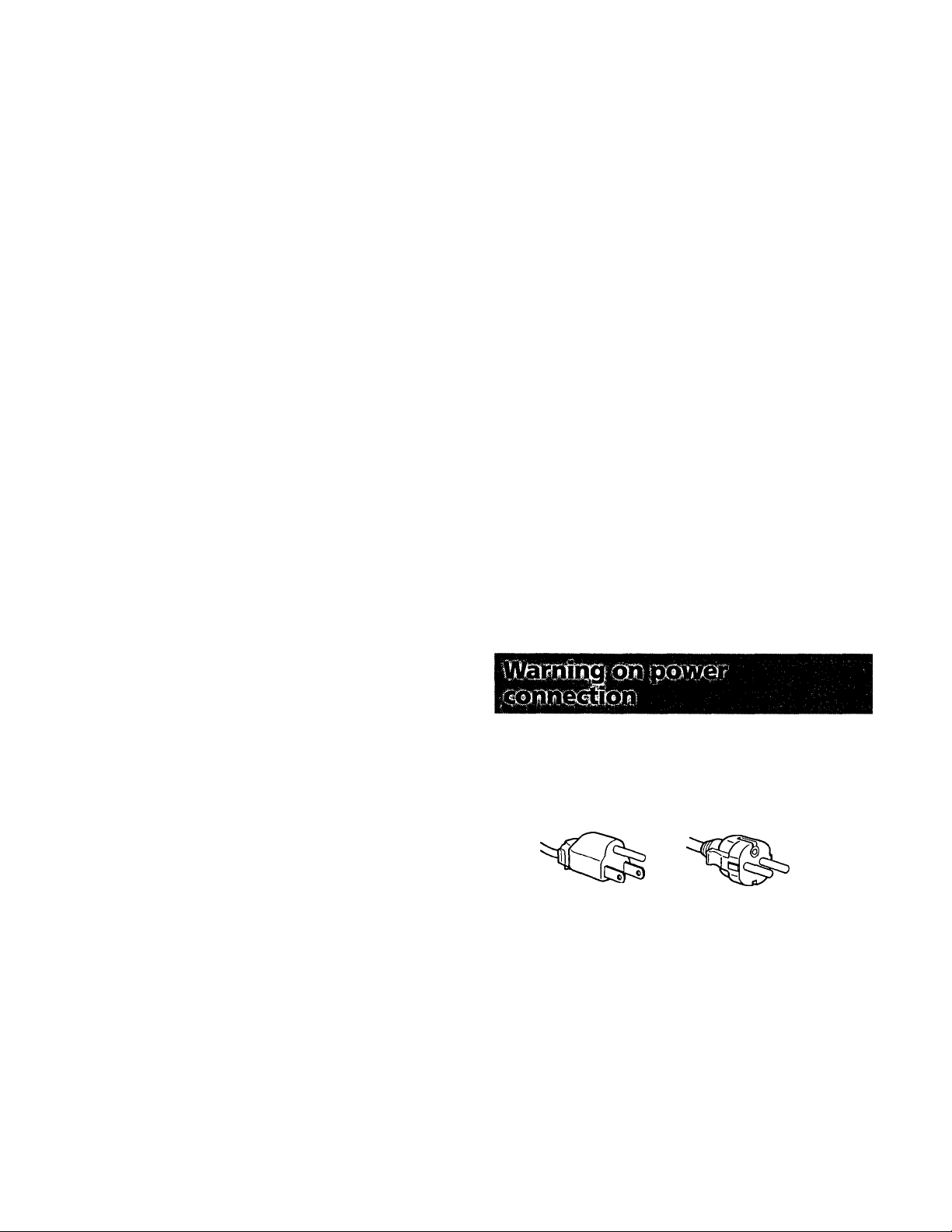
Table of Contents
Introduction........................................................................
Precautions
Connections........................................................................4
Preset Modes
Selecting the Input Signal
Functions of Controls.........................................................6
Selecting the OSD Language
Changing the OSD Position
Operating the OSD.............................................................8
Adjustments (Normal mode)..............................................9
.........................................................................
......................................................................
..................................................
.............................................
...............................................
Introduction
Congratulations on your purchase of a Sony Multiscan
series monitor.
This monitor incorporates over 25 years of Sony experience
with Trinitron® display technology, ensuring excellent
performance and outstanding reliability.
The advanced design of this monitor together with Digital
Multiscan Technology allows it to sync to any video mode
within its wide scan range.
3
3
5
5
8
8
Adjustments (Expert mode)...............................................13
Control Lock Function
Degaussing the Screen
Plug&Play.........................................................................17
Damper Wire....................................................................17
Power Saving Fimction....................................................17
Input Signal Warning Fimction........................................18
Use of the Tilt-Swivel......................................................18
Specifications
Troubleshooting
In addition, its four factory preset color modes and user
adjustable color modes give you tmprecedented flexibility
in matching on-screen colors to hard copy printouts.
Furthermore, this monitor features digital control with OSD
(On Screen Display). It delivers easier adjustment by
visualizing your control statement. All together, it delivers
incredible performance with the quality and support you
can expect from Sony.
Trinitron* is a trademark of Sony Corporation.
...................................................................
.....................................................
.....................................................
...............................................................
16
16
18
19
Precautions
• Prevent internal heat build-up by allowing adequate air
circulation. Do not place the unit on surfaces (rugs,
blankets, etc.) or near materials (curtains, draperies) that
may block the ventilation holes.
• Do not install the unit near heat sources such as radiators
or air ducts, or in a place subject to direct sunlight,
excessive dust, medtanical vibration or shock.
• Do not place the urüt near equipment which generates
magnetism, such as a converter or high voltage power
lines.
Clean the cabinet, panel cmd controls with a soft cloth
lightly moistened with a mild detergent solution. Do not
use any tjrpe of abrasive pad, scouring powder or solvent,
such as alcohol or benzine.
Do not rub, touch, or tap the surface of the screen with
sharp or abrasive items, like a ballpoint pen or a
screwdriver. This type of contact may result in a scratched
picture tube.
Use a proper power cord for your local power supply.
For the customers in UK
If you use the monitor in UK, please use the UK cable with
UK plug (not supplied).
Example of plug shape:
for too to 120 V AC
Before discormecting the power cord, wait for at least 30
seconds after turning off the power to allow the static
electricity on the CRT display surface to discharge.
After the power has been turned on, the CRT is
demagnetized for approximately five seconds. This
generates a strong magnetic field around the bezel, which
may affect the data stored on magnetic tapes or disks near
the bezel. Place such magnetic recording equipment and
tap>es/disks away from this unit.
The socket-outlet should be installed near the
equipment and be easily accessible.
for 220 to 240 VAC
When you trarvsport this morvitor for repairing or shipping,
use the original carton box and packing materials.
Page 4
Connections
Before using this monitor, check that the following items
are included in your package;
• Monitor (1)
• Video signal cable (1)
• Power cord (1)
• Macintosh’* adapter (1)
• HD15 (Female) -HD15 (Male without the No. 9 pin)
adapter (1)
• Warranty card (1)
• This operating instructions (1)
This moiütor will sync with any IBM or compatible system
equipped with VGA^* or greater graphics capability.
Although this monitor will sync with other platforms, a
cable adapter is required. Please consult your dealer for
advice on which adapter is suitable for your needs.
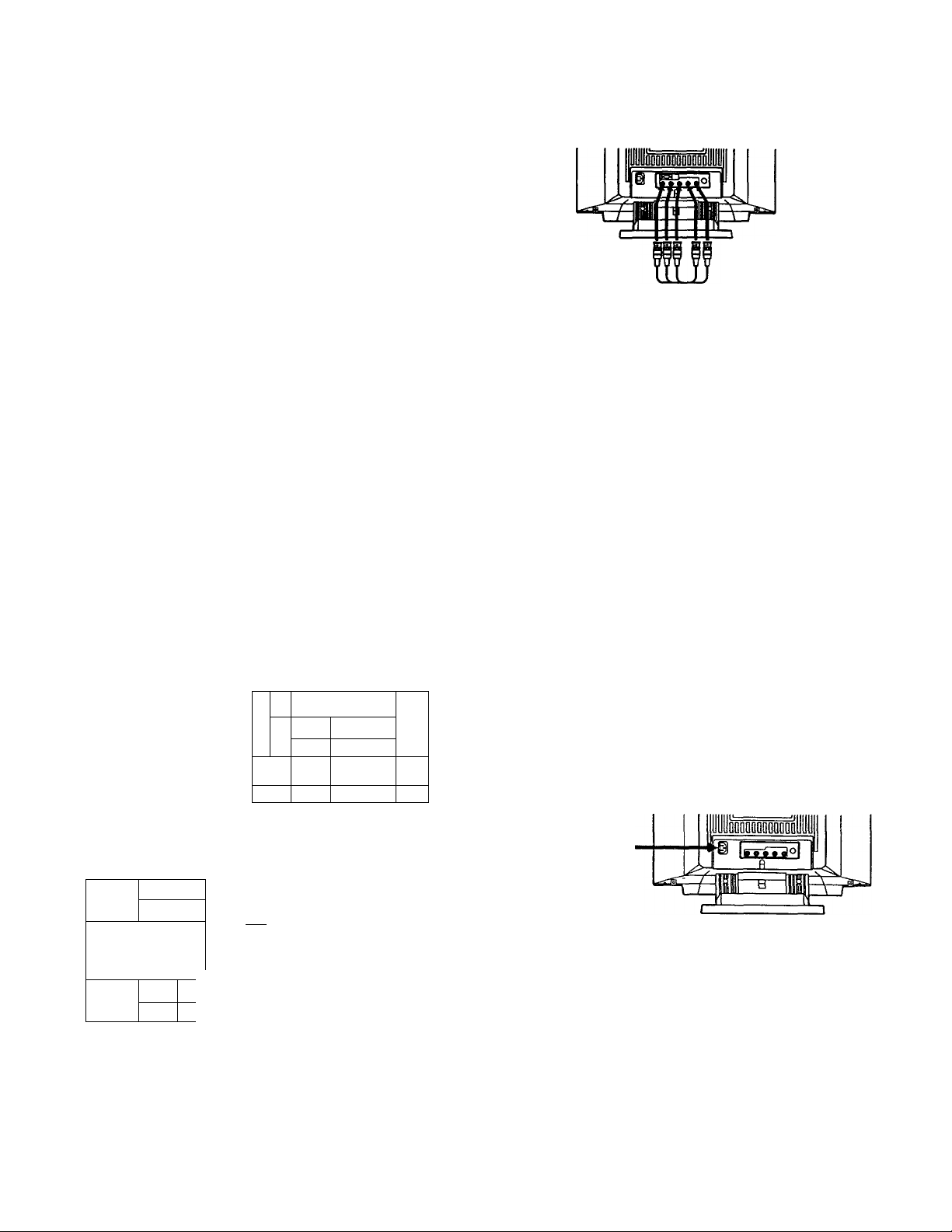
Step 1: Connect the monitor to the computer.
With the computer switched off, connect the video signal
cable to the monitor (HD15/5 BNC's) and coimect the other
end to the video output.
To connect the HD15 connector, use the supplied video
signal cable.
To cormect the 5 BNC's connector, use the SMF-400 video
signal cable (not supplied).
Note
Do not touch the pins of the video signal cable.
Connecting to the HD15 connector
u iUoDDDDOOODQDDul
A
1
_
to HD15
IBM or compatible
computer
1IÄ. "1
i ^
Macintosh computer
0 o o i=n
* The HD15-HD15 adapter may be needed for some models.
-------
j yri
to video output
H
(s
to video output
i
Macintosh adapter
(supplied)
lüfliB'Q
-----------
fl
il ^11! -
Video signal
cable
(supplied)
±:
Z1
Connecting to the 5 BNCs connector
to VIDEO IN R/G/B
Connect to the computer in the same
way as for the HD15 connector.
to SYNC IN HD/VD
Video signal cable SMF400 (not supplied)
For the customers using IBM PC or IBM compatible system which is not compatible with DDC2AB and DDC2B+
This monitor uses a No. 9 pin in the video signal connector for
DE)C2AB and DDC2B+ compatibility.
Some PC systems which are not compatible with either D1X2AB or
DDC2B+ may not accept tite No. 9 pin. If you are not sure whether
your PC system accepts the No. 9 pin or not, use the HD15 (Female)
- HD15 (Male without the No. 9 pin) adapter (supplied). Make sure
that the male side (without the No. 9 pin) is connected to the
computer.
For the customers using the Macintosh computer
Supplied Macintosh adapter is compatible witii Macintosh LC,
Performa, Quadra and Power macintosh series computers.
Macintosh n series and some older version of PowerBook models
may need an adapter with micro switches.
Step 2: Connect the power cord.
With the monitor switched off, coimect the power cord to
the monitor and the other end to the power outlet.
to a wall outlet
1—---------------GEjSn
Power cord (supplied)
The installation of your monitor is complete. Enjoy your
monitor.
Notice
To comply with the limits of FCC class B and IC Qass B for digital
device, please attach supplied video signal cable for HD15 input or
SMF-400 (not supplied) for BNC input. Furthermore, each cable
must have ferrite cores in it.
1) Macintosh and Power Macintosh are trademarks of Apple
Computer Inc.
2) VGA is a trademark of IBM Corporation.
Page 5

Preset Modes
BS
> 1 ‘ i j I 0 51
The monitor has nine factory preset modes for true "Plug &
Play" capability.
Table of preset modes
No.
Resolution
(dotsxiines)
1
640 x 480
2
720 x 400 31.5 kHz
1280 X1024 80.0 kHz 75 Hz
3
4''1600x1200
5 1920x1080
6 1920 X1080 84.4 kHz
7 1600x1024 81.3 kHz 76 Hz
8 1920 X1200
9 1920 X1035
1) VESA is a trademark of Video Electronics Standard Associatiorr.
Horizontal Vertical Graphic mode
Frequency Frequency
31.5 kHz 60 Hz VGA Graphic
70 Hz VGA Text
VESA»
93.8 kHz 75 Hz VESA
67.5 kHz 60 Hz Sony
72 Hz Sony
Sony
95.0 kHz 76 Hz Sony
33.8 kHz 60 Hz HDTV
a 'if 0 i 9 f
When using a video mcxle that is not one of the preset
modes, some fine tuning may be required to optimize the
display to your preference. Simply adjust the monitor
according to the adjustments instructions on pages 9 to 15.
The adjustments will be stored automatically and recalled
whenever that mode is used.
A total of 16 user-defined modes can be stored in memory.
If a 17th mode is entered, it will replace the first.
For less common modes, and mcxies that may evolve in the
future, the Digital Multiscan Technology of this monitor will
perform all of the complex adjustments necessary to ensure
a high quality picture for any tinung in its frequency range.
However, due to the wide variety of video boards on the
market, it may be necessary for tire user to fine tune the
vertical/horizontal size and centering.
Recommended horizontal timing conditions
Horizontal sync width should be more than 0.8 psec.
Horizontal blanking width should be more than 2.7 psec.
Note for Windows* users
Check yoiu: video board manual or the utility program
which comes with your graphic board and select the highest
available refresh rate to maximize monitor performance.
2) Windows is a registered trademark of Microsoft Corporation in
the United States and other countries.
Selecting the Input Signal
This monitor has two signal input connectors and can
connect two computers. When the power of both computers
is on, select the signal you want to input as follows.
1 Turn on power of the monitor and the computer,
2 Select the input signal.
HD15 AUTO BNC
INPUT
To input the signal from the computer connected to the 5 BNC's connector
Set the INPUT switch to BNC.
To input the signal from the computer connected to the HD15 connector
Set the INPUT switch to HD15.
3 If necessary, adjust the user controls according to
your preference on pages 9 to 15.
When you set the INPUT switch to "AUTO"and connect computers to both connectors
If you turn on or restart the computer you want to input a signal
from, or the computer is in power saving mode, the monitor may
automatically select another computer's signal. This is because no
signal is input to the monitor at that moment. If this happens,
select the signal using the INPUT switch.
For the customers using the Windows95
Even if you select SONY for the maker on the device select screen,
the model name (GDM-W900) may not appear. In this case, select
the DDC standard monitor.
If only one computer is connected or turned on
Set the INPUT switch to AUTO (center position). The
input signal is automatically selected.
Page 6
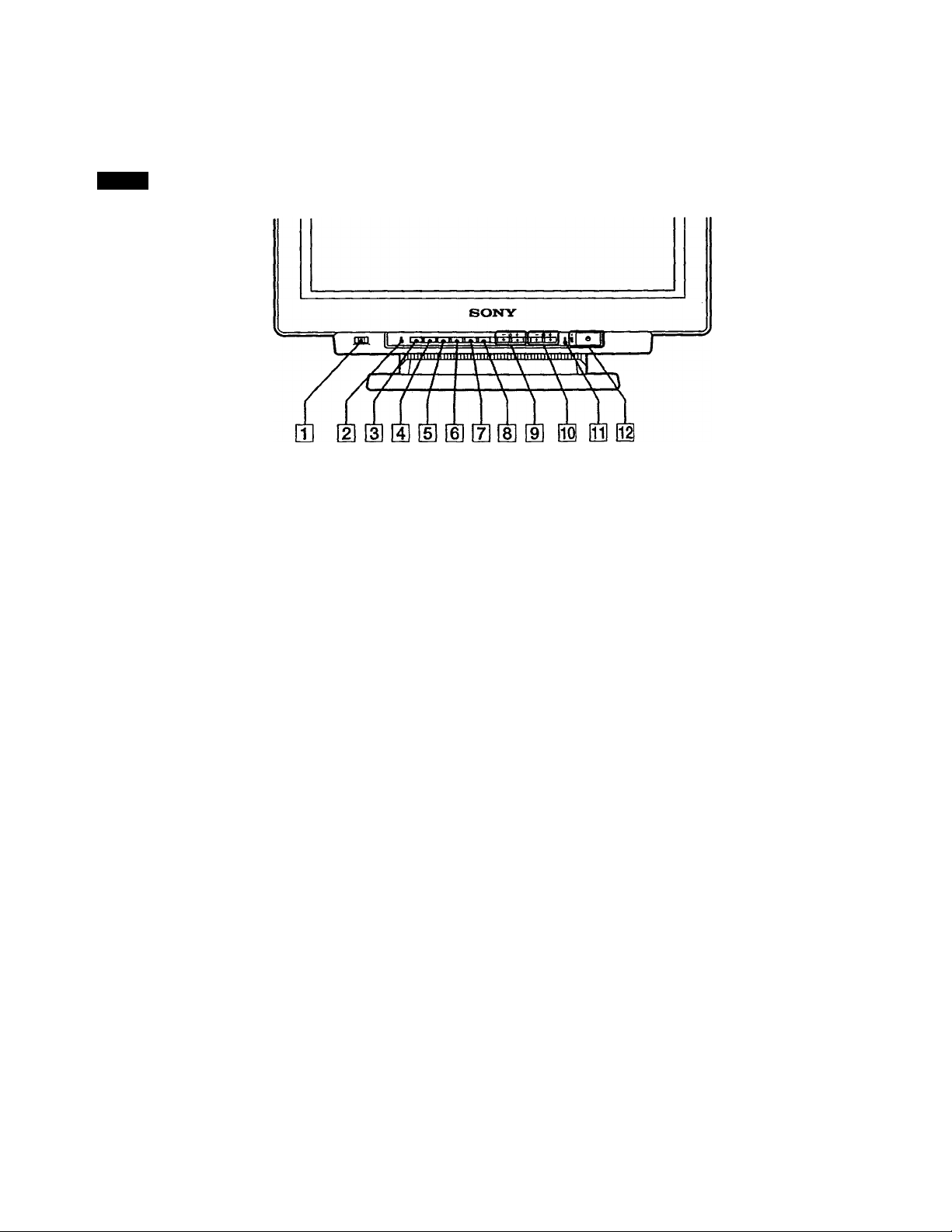
Functions of Controls
See the given pages for further description.
Front
[T] INPUT switch (page 5)
Selects the input signal.
(H RESET button (page 12)
Resets the adjustment to the factory preset levels.
[3] OPTION button (pages 8, 9.13,16)
Displays the "OPTION" OSD (On Screen Display).
[D COLOR button (pages 12,15)
Displays the "COLOR" OSD to adjust color
temperatiue.
[5] SCREEN button (pages 11,14)
Displays the "SCREEN" OSD to adjust the vertical and
horizontal convergence, etc.
d] GEOM (geometry) button (pages 10,14)
Displays the "GEOMETRY" OSD to adjust the picture
rotation and pincushion, etc.
[7] SIZE button (pages 10,14)
Displays the "SIZE" OSD to adjust the picture size.
[8] CENT (center) button (pages 10,14)
Displays the "CENTER" OSD to adjust the picture
position.
53 (contrast) -/+ (■4"/■►) buttons (pages 8 •
16)
Adjust the contrast.
Act as the -/+ (4“/■♦■) buttons when adjusting other
items.
53 POWER SAVING indicator (page 17)
Lights up when the monitor is in the Power Saving
Mode.
51 (I) power switch and indicator (page 17)
Turns the monitor on or off. The indicator lights up
when the monitor is turned on.
[9] iii (brightness) -/+ (f/f) buttons (pages 8
-16)
Adjust the picture brightness.
Act as the -/+ (4^/f) buttons when adjusting other
items.
Page 7
OPTION OSD
[3]—
OPTION
► LANGUAGE
-OSD POSITION: RIGHT BOTTOM
-OSD MENU
-LOCK
_________
■JPN -ENG -FRAI
•DEU -ESP -ITa I
■NORMAL -EXPERT
_
■UNLOCK -LOCK
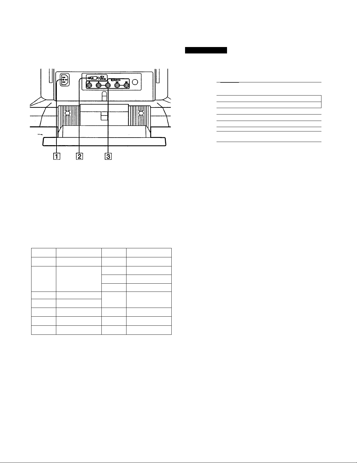
[T] AC IN connector
Plug in an AC power cord.
[2] Video input 1 connector (HD15)
Inputs RGB video signal (0.714 Vp-p, positive) and
SYNC signal.
®@(3)(2)®
Pin No. Signal
1 Red 8
2 Green
(Composite
Sync on Green)
3 Blue
4 Ground
5 DDC Groimd- 13
6 Red Ground
7 Green Ground 15
Pin No. Signal
Blue Ground
9 DDC + 5V*
10
11
Ground
Ground
12 Bi-Directional
Data (SDA)*
H.Sync
14 V. Sync
Data Clock(SCL)*
-(INPUT: BNC
Q Q SELECT B B SET
84.4kHz/72Hz J
U] LANGUAGE (page 8)
Selects an OSD language, Japanese, English, French,
Germaiv Spanish, or Italian.
[U OSD POSITION (page 8)
Changes the OSD position to be displayed.
[U OSD MENU (pages 9, 13)
Selects the adjustment mode, normal or expert.
g] LOCK (page 16)
Turns on or off the control lock fimction.
H] INPUT (pages 5,18)
Shows the current active connector, the BNC cormectors
or the HD15 connector, and the signal frequency.
Display Data Channel (DDC) Standard by VESA
0
Video input 2 connector (5 BNC)
Inputs RGB video signal (0.714 Vp-p, positive).
Page 8

Selecting the OSD Language
Japanese, English, French, German, Spanish, or Italian
versions of OSD are available.
1 Press the OPTION button.
The "OPTION" OSD appears.
OPTION
2 Press the button to select "LANGUAGE.'
3 Press the 9^/^ button to move the OSD to the
desired position.
- 3 +
b
The "OPTION" OSD automatically disappears after about 30
seconds. To turn off the OSD, press the OPTION button
again.
— ^ +
3 Press the button to select the desired
language.
- 3 +
OPTION
►LANGUAGE
OSD POSITION: RIGHT BOTTOM
OSD MENU
LOCK •UNLOCK -LOCK
INPUT: BNC 84.4kHz,'72Hz
Q D SELECT B B SET
■JPN -ENG -FRA
•DEU -ESP *ITA
•NORMAL -EXPERT
b
JPN: Japanese, ENG: English, FRA: French,
DEU: German, ESP: Spanish, IT A: Italian
The "OPTION" OSD automatically disappears after about
30 seconds. To turn off the OSD, press the OPTION button
again.
Changing the OSD
Operating the OSD
Select a parameter using the 1' buttons in the OSD
which parameters are arranged in vertical row, md adjust or
select the setting of the selected parameter using the
9-^/buttons.
To select a parameter to adjust or select the setting, press or ♦ button.
The green ► mark goes to the selected parameter and the
parcimeter becomes yellow.
— ^ +
I.
To adjust or select the settings of the selected parameter, press or ^ button.
When adjusting, the bar length md the figure increase or
decrease.
When selecting the setting, the green ■ goes to the selected
setting. _ +
Position______________
You can change the OSD position, for example, when you
want to adjust the picture behind the OSD.
1 Press the OPTION button.
The "OPTION" OSD appears.
2 Press the lii f/f button to select "OSD POSITION".
- -ft +
ft)
8
OPTION
LANGUAGE •JPN -ENG -FRA
►OSD POSITION: RIGHT BOTTOM
OSD MENU
LOCK
INPUT: BNC
D D SELECT B B SET
■DEU -ESP -ITA
•NORMAL -EXPERT
■UNLOCK -LOCK
84.4kHz,' 72Hz
US
b
Page 9

Adjustments (Normal mode)
You can adjust five picture to your preference.
This monitor has two levels of adjustment mode, normal
and expert.
Before adjusting
• Connect the monitor and the computer, turn them on and
feed the signal to the monitor.
• Select "LANGUAGE" in the "OPTION" OSD, then select
"ENG" (English) on page 8.
Ws 'ШЙ i 15 L
1 Pré» the OPTION button.
The "OPTION" OSD appears.
OPTION
OPTICW
►LANGUAGE «JPN -ENG -FRA
OSD POSITION: RIGHT BOTTOM
OSD MENU iNOFMAL -EXPERT
LOCK -UNLOCK -LOCK
INPUT; BNC 84.4kHz/72Hz
0 Q SELECT SET
•DEU ‘ESP -ITA
2 Press the ■ii-f/'t' button to select "OSD MENU."
The "OSD MENU" becomes yellow.
in - и '. f - I'
' r M
The adjustment data becomes the common setting for all
input signals received.
1 Press theTiT (brightness) ■f/'t button.
The "BRIGHTNESS/CONTRAST" OSD appears.
- * +
2 Press the button again to adjust picture
brightness.
4^... for less brightness
4 ... for more brightness
The OSD automatically disappears after about 3 seconds.
To reset, press the RESET button while the OSD is on. The
brightness and contrast are both reset.
OPTION
+
LANGUAGE -JPN -ENG -FRA
OSD POSITION: RIGHT BOTTOM
►OSD MENU -NORMAL -EXPERT
LOCK -UNLOCK -LOCK
INPUT: BNC 84.4kHz/72Hz
n a SELECT В В SET
■DEU -ESP -ITA
3 Press the button to select NORMAL
Move the green ■ to NORMAL.
- Э +
±J
The "OPTION" OSD automatically disappears after about
30 seconds. To turn off the OSD, press the OPTION button
again.
OPTION
LANGUAGE
OSD POSITION: RIGHT ВОТТШ
►OSD MENU
LOCK
INPUT: BNC
0 0 SELECT
-JPN -ENG -FRA
■DEU -ESP -ITA
-NORMAL -EXPERT
-UNLOCK -LOCK
84.4kHz,' 72Hz
В В SET
The adjustment data becomes the common setting for all
input signals received.
1 Press the 3 (contrast) button.
The "BRIGHTNESS/CONTRAST" OSD appears.
2 Press the button again to adjust picture
contrast.
4"... for less contrast
■♦•... for more contrast
The OSD automatically disappears after about 3 seconds.
To reset, press the RESET button while the OSD is on. The
brightness and contrast are both reset.
Page 10

Adjustments (Normal mode)
f'i=
Irii)
The adjustment data becomes the individual setting for each
input signal received.
1 Press the CENT button.
The "CENTER" OSD appears.
CENT
2 For vertical adjustment
Press the 'I'/1 buttons.
— ■ij' +
b
4^... to move down
4 • ■ • to move up
For horizontal adjustment
Press the 9 •4“/buttons.
- 3 +
2 For vertical adjustment
Press die 4/4 buttons.
- +
b
4.. . to decrease
4.. . to increase
For horizontal adjustment
Press the 3 ■4“/^ buttons.
- 3 +
±3
b
◄"... to decrease
^... to increase
The OSD automatically disappears after about 10 seconds.
To turn off the OSD, press the SIZE button again.
To reset, press the RESET button while the OSD is on. The
horizontal and vertical sizes are both reset.
79
•^... to move left
^... to move right
The OSD automatically disappears after about 10 seconds.
To turn off the OSD, press the CENT button again.
To reset, press the RESET button while the OSD is on. The
horizontal and vertical centerings are both reset.
The adjustment data becomes the individual setting for each
input signal received.
1 Press the SIZE button.
The "SIZE" OSD appears.
SIZE
SIZE
S3
23
Zl 0 H !■
10
0
□ 0
The adjustment data becomes the common setting for all
input signals received.
1 Press the GEOM button.
The "GEOMETRY" OSD app>ears.
GEOM
6E0WETRY
□ IM
23
□ OB W"" 1B
Q
10
2 Press the buttons.
— -iCi- +
4 ... to rotate counterclockwise
■f'... to rotate clockwise
The OSD automatically disappears after about 10 seconds.
To turn off the OSD, press the GEOM button again.
10
To reset, press the RESET button while the OSD is on. The
picture rotation and the pincushion settings are both reset.
Page 11

The adjustment data becomes the individual setting for each
input signal received.
o
1 Press the GEOM button.
I
The "GEOMETRY" OSD appears.
GEOM
2 Press the button so that the picture edges
GEOMETRY
„ О
Ol—
23 10
□ 0 ON '
£3
□ B
become straight
- 3 +
u
ft)
The OSD automatically disappears after about 10 seconds.
To turn off the OSD, press the GEOM button again.
To reset, press the RESET button while the OSD is on. The
picture rotation and the pincushion settings are both reset.
1 Press the SCREEN button.
The "SCREEN" OSD appears.
Convergence
Ihe adjustment data becomes the common setting for all
input signals received.
Press the button so that the red or blue
shadow disappears.
'H CONVERGENCE" (Horizontal convergence)
◄"... to move Red to the left and Blue to the right
■♦... to move Red to the right and Blue to the left
"V CONVERGENCE' (Vertical convergence)
•^... to move Red down and Blue up
^... to move Red up and Blue down
Canceling the Moire
The adjustment data becomes the individual setting for each
input signed received.
Press the 0^/*^ button to select "ON" for "CANCEL MOIRE."
If the picture becomes unclear
The picure may become unclear by canceling moire.
1 Press the button to select "MOIRE ADJ."
2 Press the button to adjust beginning from 0
until the moire is minimum.
Landing
Correct when the color is not uniform due to influence from
the earth's magnetizm.
The adjustment data becomes the common setting for all
input signals received.
First, degauss the screen, then display an entirely white
picture for more than 20 minutes before the adjustment to
adjust more accurately.
SCREEN
2 Press the button to seiect the parameter you
SCREEN
►H CONVERGENCE
V CONVERGENCE
CANCEL MOIRE
MOIRE ADJ
LANDING
DEGAUSS
a 0 SELECT
тшшшшшт 1
шшшшт
•OFF «ON
1
--------
n
ADJUST-^
•ON
В S SET/ADJUST
85
72
want to adjust referring to the foilowing.
The selected parameter turns yellow.
The OSD automatically disappears after about 30 seconds.
To turn off the OSD, press the SCREEN button again.
To reset, press the RESET button while the OSD is on. The
selected parameter is reset.
1
Press the ^4/t button to select "DEGAUSS." Press the 0*^ button.
2
0
The screen is degaussed for about five seconds.
Press the button to select "LANDING."
3
4
Press the 0*^ button.
The "LANDING" OSD appears on the screen.
- 3 +
LANDING
►SCREEN MENU -►
CENTER TOP/ВОТ
LEFT TOP
RIGHT TOP
RIGHT BOTTOM
LEFT BOTTOM
D n SELECT В В ADJUST
5 Press the button to select the position, and
adjust by pressing the 0 button.
To return to the "SCREEN" OSD, select "SCREEN MENU
and press the 0-^ button.
To reset, press the RESET button while the OSD is on. The
selected parameter is reset.
11
Page 12

Adjustments (Normal mode)
r V.! Г| ‘■.Ti il riij 5 ri ? ‘I.c)] О r’
f‘-_> <l I Г-)
The adjustment data becomes the common setting for all
input signals received.
1 Press the COLOR button.
The "COLOR" OSD appears.
COLOR
^LOR
COLOR TEMPERATURE
■5000K -6500K -9300K
VARIABLE
n n SELECT e e SET/ADJUST
2 Press the buttons to select a color
temperature.
The factory settings are:
5000K, 6500K, 9300K
Adjusting the color temperature
Press the ♦ button to select "VARIABLE," and
adjust by pressing the button.
The figure of the adjusted color temperature changes.
The OSD automatically disappears after about 30 seconds.
To turn off the OSD, press the COLOR button again.
Resetting the picture size, position, moire, and geometry* at the same time
When there is no OSD displayed, press and hold the RESET button for one second.
The above items of the current input signal are reset to
factory-preset levels.
* The "Rotation" adjustment (pages 10,14) is not reset.
To reset, press the RESET button while the OSD is on. The
selected color tempetarure is reset. The adjustments you
made in the expert mode (page 15) are also reset.
'„fiisl* J
1 Press the button of the OSD you want to reset to the
factory setting.
2 When the parameters are arranged in vertical row in
the OSD, select a parameter you want to reset by
pressing the buttons.
3 Press the RESET button.
RESET
Resetting ail adjustment data
When there is no OSD displayed, press and hold the RESET button for more than two seconds.
All adjustment data including the brightness and contrast
are reset to factory-preset levels.
12
Page 13

Adjustments (Expert mode)
You can adjust more in detail in the expert mode than in the
normal mode.
Before adjusting
• Connect the monitor and the computer, turn them on and
feed the signal to the monitor.
• Select "LANGUAGE" in the "OPTION" OSD, then select
"ENG" (English) on page 8.
1 Press the OPTION button.
The "OPTION" OSD appears.
OPTION
2 Press the ii-f/t button to select "OSD MENU."
OPTION
►LANGUAGE »JPN -ENG -FRA
OSD POSITION: RIGHT BOTTOM
OSD MENU -NORMAL -EXPERT
LOCK -UNLOCK -LOCK
INPUT: BNC 84,4kHz/72Hz
B B SELECT a B SET
■DEU -ESP -ITA
The "OSD MENU" turns yellow.
OPTION
-
I
LANGUAGE -JPN -ENG -FRA
OSD POSITION: RIGHT BOTTOM
►OSD MENU -NORMAL -EXPERT
LOCK -UNLOCK -LOCK
INPUT: BNC 84.4kHz/72Hz
B B SELECT
•DEU -ESP -ITA
B e SET
K*—
The adjustment data becomes the common setting for all
input signals received.
1 Press the button or the button.
The "BRIGHTNESS/CONTRAST" OSD appears.
BRIGHTNESS/CONTRAST
►(•CONTRAST !■ " 1 10
•&BRIGHTNESS 1» I 23
№ESET -1 -2 -3
B B SELECT 8 B SET/ADJUST
2 Press the ■Cl'f/♦ button to select "PRESET" and the
9 button to select a preset number.
When you want to use the monitor later in the same
condition, just select the same preset number.
3 Press the button or the button to
adjust the brightness or contrast
BRIGHTNESS:
Adjusts the picture brightness.
3 CONTRAST:
Adjusts the pictiure contrast.
The OSD automatically disappears after about 30 seconds.
To tiun off the OSD, press the ♦ or button
again.
3 Press the button to select "EXPERT."
Move the green ■ to EXPERT.
appears at the top right comer of the OSD in
Expert mode.
- 3 +
im
OPTION
LANGUAGE
OSD POSITION: RIOIT BOTTOM
►OSD MENU
LOCK
INPUT: BNC
B B SELECT
-JPN -ENG -FRA
•DEU -ESP -ITA
•NORMAL -EXPERT
■UNLOCK -LOCK
84,4kHz/72Hz
S B SET/ADJUST
The "OPTION" OSD automatically disappears after about
30 seconds. To turn off the OSD, press the OPTION button
again.
To reset, press the RESET button while the OSD is on. The
selected preset number is reset
13
Page 14

Adjustments (Expert mode)
ilft'J -ili-'
The adjustment data becomes the individual setting for each
input signal received.
Press the SIZE button or the CENT button.
1
The "CENTER/SIZE" OSD appears.
CENTER/SIZE
►C3H CENTER
QV CENTER
Si SIZE
GOV SIZE
B a SELECT E В ADJUST
■
IS
liS
es
......
......
------
2 Press the button to select and the 3
button to adjust the parameter.
O H CENTER:
Adjusts the picture position in horizontal direction.
0 V CENTER:
Adjusts the picture position in vertical direction.
HSIZE:
Adjusts the picture size in horizontcd direction,
GO VSIZE:
Adjusts the picture size in vertical direction.
The OSD automatically disapjjears after about 30 seconds.
To turn off the OSD, press the SIZE or CENT button again.
watM
ZD 10
Z3 10
Z3 23
ZD 23
2 Press the Ijf button to select and the Э
button to adjust the parameter.
О H PINCUSHION/ a H PIN BAL
Corrects the picture distortion of the picture edges.
О H KEYSTONE:
Corrects the difference of picture size at the top and
bottom.
О H KEY BAL
Corrects the imbalance of picture position at the top and
bottom.
О ROTATION:
Corrects the picture rotation,
a
S PINCUSHION/a SPINBAL/q CBOW:
Corrects the wavy distortion of the picture edges.
О flare TOP/
n
flare ВОТ:
Corrects the flare distortion of the picture at the top and
bottom.
m V UNEARITY/ в V UN BAL
Corrects the vertical linearity and the vertical linearity
balance.
The OSD automatically disappears after about 30 seconds.
To turn off the OSD, press the GEOM button again.
To reset, press the RESET button wMle the OSD is on. The
selected parameter is reset.
umi)
To reset, press the RESET button while the OSD is on. The
selected parameter is reset. .
The adjustment data becomes the individual setting for each
input signal received.
1 Press the GEOM button.
The "GEOMETRY" OSD appears.
GEa.1ETRY
►E3H PINCUSHION
OH PIN BAL
OH KEYSTONE
QH KEY BAL
CAROTATION
OS PINCUSHION
OS PIN BAL
OC boy;
OFLARE TOP
OF LARE BOT
ev LINEARITY
BV LIN BAL
D D SELECT В C ADJUST
Press the SCREEN button.
The "SCREEN" OSD appears.
SCREEN
►H CONVERGENCE
V CONVERGENCE
V CONV TOP
V CONV ВОТ
H FOCUS
CANCEL MOIRE
MOIRE ADJ
LANDING ADJUST-*
DEGAUSS
0 a SELECT
{■■■iHi 1 79
(■■■■■I 7^
•OFF -ON
•ON
В Б SET/ADJUST
ffillXII
i 35
ion
rnmm D 50
1 1 0
Press the button to select and the
button to adjust the parameter.
H CONVERGENCE/V CONVERGENCE:
Adjusts the horizontcd convergence and the vertical
convergence.
The adjustment data becomes the common setting for all
input signals received.
V CONV TOP/V CONV ВОТ:
Adjusts the vertical convergence at the top and bottom
of the screen.
The adjustment data becomes the common setting for all
input signals received.
14
H FOCUS:
Adjusts the horizontal focusing.
The adjustment data becomes the common setting for all
input signals received.
Page 15

CANCEL MOiRE:
Cancels the moire when "ON" is selected.
The adjustment data becomes the individual setting for
each input signal received.
MOIRE ADJ:
Reduces fuzziiess of the picture caused by canceling
moire.
Adjust beginning from 0 imtil the moire is minimum.
The adjustment data becomes the individual setting for
each input signal received.
LANDING:
See "Landing" on page 11.
~~ The adjustment data becomes the common setting for all
input signals received.
DEGAUSS:
See "Degaussing the screen" on page 16.
The OSD automatically disappears after about 30 seconds.
To turn off the OSD, press the COLOR button again.
To reset ail parameters of a particular color
temperature
Select the color temperature in step 2, and then press the
RESET button. All parameters of the color temperature are
reset and "++" at the right shoulder disappears.
To reset a particular parameter of a particular color
temperature
Select the parameter in step 3, and then press the RESET
button. Only the selected parameter of the color
temperature is reset.
' IfciKl ^ il'" li' i! r ’ P'ui
The OSD automatically disappears after about 30 seconds.
To turn off the OSD, press the SCREEN button again.
To reset, press the RESET button while the OSD is on. The
selected parameter is reset.
The adjustment data becomes the common setting for all
input signals received.
1 Press the COLOR button.
The "COLOR" OSD appears.
COLOR
►COLOR TBiPERATUPE
-5000K • 3500K -9300K
VAR I ABLE
R BIAS
G BIAS
B BIAS
R GAIN
G GAIN
B GAIN
0 Q SELECT
\mÈmm
\mmmrn
\wrnmm
B B SET/ADJUST
I"“
] 100
] 50
] 50
] 60
] 50
] 50
] 50
Press the 3-4-/«^ button to select the color
temperature to adjust 5000, 6500 or 9300.
Reset in the same way as described in "Resetting to the
factory-preset levels" on page 12.
Press the iii'f/'f button to select and the
button to adjust the parameter.
VARIABLE:
Adjusts the color selected in step 2 to the desired color
temperature. The figure of the selected color
temperature changes.
R BIAS/G BIAS/B BIAS:
Adjusts the black level of each signal. "++" app>ears at
the right shoulder of the adjusted color temperature.
R GAIN/G GAIN/B GAIN:
Adjusts the white level of each signal. "++" appears at
the right shoulder of the adjusted color temperature.
15
Page 16

Control Lock
Degaussing the
Function
The control lock function disables all the buttons on the
front panel except the (!) (power) and OPTION buttons and
the INPUT switch.
1 Press the OPTION button.
The "OPTION" OSD appears.
OPTION
►LANGUAGE -JPN -ENG -FRA
OSD POSITION: RIGHT BOTTaJl
OSD MENU -NORMAL -EXPERT
%
2 Press the 13 4/t button to select "LOCK."
3 Press the button to select “LOCK."
The "OPTION" OSD automatically disappears after about
30 seconds. To turn off the OSD, press the OPTION button
again.
Once you select "LOCK," you carmot select other item on
the "OPTION" OSD using the li 't' button.
If you press any button other than the (!) (power) and
OPTION buttoiTS and the INPUT switch, the Ofl mark
LOCK -UNLOCK -LOCK
INPUT: BNC 84,4kHr/72Hz
B 0 SELECT e B SET
appears on the screen.
•DEU -ESP -ITA
Screen
The screen of the monitor is automatically degaussed when
the power is turned on (page 3).
You can degauss manually.
1 Press the SCREEN button.
The "SCREEN" OSD appears.
SCREEN
2 Press the button to select "DEGAUSS."
3 Press the 3 ^ button.
The screen is degaussed for about five seconds.
SCREEN
►H CONVERGENCE
V CONVERGENCE
CANCEL MOIRE
MOIRE ADJ
LANDING
DEGAUSS
D 0 SELECT B fi SET/ADJUST
Wmmmm ~1
•OFF -ON
r ■ ■ 1
ADJUST—
•ON
I
85
72
0
To cancel the control lock
Press the O ■♦■/“♦ button to select "UNLOCK."
Note
Use the control lock function only when necessary.
16
Page 17

Plug & Play
This monitor complies with the DDC™1, DDC2B and
DDC2AB which are the Display Data Chaimel (DDC)
standards of VESA.
When a DDCl host system is connected, the monitor
synchronizes with the V. CLK in accordance with the VESA
standards and outputs the EDID (Extended Display
Identification Data) to the data line.
When a DDC2B or DDC2AB host system is connected, the
monitor automatically switches to each communication.
DDC™ is a trademark of Video Electronics Standard Association.
Damper Wire
Using a white backgroimd, very thin horizontal lines on the
screen are visible as shown below. These lines are damper
wires.
The Trinitron tube has a vertically striped Aperture Grill
inside. The Aperture Grille allows more light to pass
through to the screen giving the Trinitron CRT more color
and brightness.
These damper wires are attached to the Aperhure Grille to
prevent vibration of the Aperture Grille wire so that the
screen image is constantly stable.
Power Saving Function
This monitor is capable of three states of reduced power
consumption. By sensing the absence of video signals and
one or both sync signals coming from the host computer, it
will reduce power consumption as follows.
Power Power
consumption consump-
state don
Normal ¿200W
1
operation
Standby ¿140W
2
(1st state)
Suspend <15W
3
(2nd state)
Active-off <8W
4
(3rd state)
Power-off
5
• The H-sync is not present.
The unit goes into standby state.
OW
Recovery
time
—
Approx. Orange on
3sec
Approx.
3 sec.
Approx.
10 sec.
—
POWER
SAVING
indicator
Off
Orange on
Orange on
Off
(1) (power)
indicator
Green on
Green on
Green on
Off
Off
Damper wire
• The V-sync is not present.
The unit goes into suspend state.
• Both the H-sync and V-sync cue not present.
The unit goes into active-off state.
The monitor requires a video card or screen saver software
which switches off one or both sync signals to activate the
power saving function.
Caution
If no video signal is input to the monitor, or if the INPUT
switch is set to the cormector to which no signal is input
when you turn on the monitor, the input signal warning
indicator (page 18) appears. After 30 seconds, the Power
Saving function automatically puts the monitor into the
Active-off state and the POWER SAVING indicator lights
up. Once the horizontal and vertical syncs are sensed, the
monitor will automatically return to its Normal op>eration
state.
17
Page 18

Input Signal
Use of the Tilt-
Warning Function
If there is something wrong with the input signal, one of the
following messages appears when you turn the monitor off
and on, or when you operate the INPUT switch.
The message disappears after about 30 seconds.
[T] Shows the INPUT switch setting.
[2] Shows the input signai condition.
"FH: - kHz" indicates no horizontal sync signed.
"FV: - Hz" indicates no vertical sync signal.
"OUT OF SCAN RANGE" indicates that the input signal
is not supported by the monitor's specifications.
"NO CONNECTION" indicates that the supplied video
signal cable is disconnected from the HD15 cormector
when the INPUT switch is set to "HD15."
Swivel
With the tilt-swivel, this unit can be adjusted to be viewed
at the desired angle within 310° horizontally and 20°
vertically.
To turn the unit vertically and horizontally, hold it at its
bottom with both hands as illustrated below.
Specifications
Picture tube
Viewable image size
Resolution
Stcmdard image area
Deflection frequency
Input
AC input voltage/current
Power consumption
Dimensions
Mass
0.25 - 0.28 mm aperture grille pitch
24 inches measured diagonally
90-degree deflection
Approx. 482 X 304 mm (w/h)
(19 X12 inches)
22.5" viewing image
Horizontal: Max. 1920 dots
Vertical: Max. 1200 lines
Approx. 473 X 296 mm (w/h)
(18 ®/s X11 ^/4 inches)
Horizontal: 30 to 96 kHz
Verticcd: 50 to 160 Hz
HD15 (1), 5 BNC (1)
R/G/B: 75 il, 0.714 Vp-p, positive
HD/VD or Comjx)site sync
Sync-on-green: 0.286 Vp-p,
negative
100 to 120 V, 50/60 Hz, 2.2 A
200 to 240 V, 50 - 60 Hz, 1.4 A
Max. 200 W
580 X 500 X 548 mm (w/h/d)
(22 ^/8 X 19 ^/4 X 21 ®/8 inches)
Approx. 41 kg (90 lb 6 oz)
18
Design and specifications are subject to change without
notice.
Page 19

Troubleshooting
This section may help you isolate a problem emd as a result, eliminate the need to contact technical support, allowing
continued productivity.
Note the model name and the serial number of your monitor. Also note the make and name of your computer and video
board.
Symptom
No picture
If neither (!) (power)
indicator nor POWER
SAVING indicator is lit
If the POWER SAVING
^dicator is lit
If the (!) (power) indicator
is flashing in green
If the (!) (power) and/or
POWER SAVING
indicators are flashing in
orange
If you do the above
procedures and the
monitor does not recover
Check these items
• Check that the power cord is properly connected.
• Check that the (!) (power) switch is in the "on" position.
• Check that your computer power switch is in the "on" position.
• The monitor will recover when you press any key on the keyboard of the computer.
• The INPUT switch setting is incorrect.
• Check that the video signal cable is properly connected and all plugs are firmly seated in
their socket.
• Check that the 5 BNC's are connected in the correct order (from the power cord side:
Red-Green-Blue-HD-VD).
• Ensure that no pins are bent or pushed in the HD15 video input connector.
• Check that the video board is seated completely in the proper bus slot.
• Check that the video frequency range is within that specified for the monitor.
(Horizontal: 30 - 96 kHz, Vertical: 50 -160 Hz)
• Turn the monitor off and on. If the indicator is off, the monitor is in the normal
condition. If the indicator is still flashing, there is a potential monitor failure.
• Unplug the video input 1 and 2 connectors and wait for 5 seconds. Then press and hold
the O + button for 2 seconds to display the color bars. If the color bars appear, the
monitor may be in normal condition. Turn the monitor off and on to return to the
normal operation mode. If the color bars do not appear, there is a potential monitor
failure.
If using a Macintosh
system
If using a Windows95
Picture is scrambled
Color is not uniform
You cannot adjust the
monitor with the buttons on
the front panel
White does not look white
• Check that the Macintosh adapter and the video signal cable are properly connected,
and the dip switches of the adapter are properly set.
• When you cannot find "GDM-W900" among the Sony monitors on the Windows95
device select screen, select the DDC standard monitor.
• Check your graphic board manual for proper monitor setting.
• Check this manual and confirm that the graphic mode and the frequency at which you
are trying to operate is supported (page 5). Even within the proper range some video
boards may have a sync pulse that is too narrow for the monitor to sync correctly.
• Degauss the monitor (page 16).
If you place equipment which generates a magnetic field such as a loudspeaker, or you
change the direction of the monitor, color may lose uniformity.
This function is to demagnetize the metal frctme of the CRT to obtain a neutral field for
uniform color reproduction. If a second degauss cycle is needed, allow a minimum
interval of 20 minutes for the best result.
• Adjust the landing (page 11).
• If the control lock fimction is set to on, set it to off on the OPTION OSD (page 16).
You will be able to adjust the monitor.
• Adjust color (page 12,15).
• Check that the 5 BNC's are connected in the correct order (from the power cord side:
Red-Green-Blue-HD-VD).
Continued to the next page
19
Page 20

Troubleshooting
Symptom
Screen image Is not centered
or sized properly
Edges of the image are
curved
White lines show red or blue
shades at edges
Picture is fuzzy
Picture bounces or has wavy
oscillations
Check these items
• Adjust tile centering or size (pages 10,14).
• Some video modes do not fill the screen to the edge of the monitor. There is no single
answer to solve the problem. This problem tends to occur on higher refresh timings.
• Adjust the geometry items such as pincushion and keystone distortion (page 11,14).
• Adjust the convergence (pages 11,14).
• Adjust the contrast and brightness (page 9).
• Degauss the monitor (page 16).
If you place equipment which generates a magnetic field such as a loudspeaker, or you
change the direction of the monitor, color may lose uniformity.
This function is to demagnetize the metal frame of the CRT to obtain a neutral field for
uniform color reproduction. If a second degauss cycle is needed, allow a mirumum
interval of 20 minutes for the best result.
• If red or blue shades are foimd at the edge of images, adjust the convergence (pages 11,
14).
• If the moire is cancelled, the picture may become fuzzy. Adjust so that the picture is as
clear as possible (page 11,15).
• Isolate and eliminate any potential sources of electric or magnetic fields. Common causes
for this symptom are electric fans, fluorescent lighting, laser printers, and so on.
• If you have another monitor close to this monitor, increase the distance between them to
reduce the interference.
• Try plugging the monitor into a different AC outlet, preferably on a different circuit.
• Try the monitor on a completely different computer in a different room.
Picture is not stable
Picture appears to be
ghosting
Two fine horizontal lines
(wires) are visible
Wavy or elliptical (moire)
pattern is visible
Hum is heard right after the
power is turned on
Because of vibration and
shock during transportation,
the Aperture Grille may
occasionally slip out of place
and black stripes may
appear
• Set the refresh rate to non-interlace of 75 Hz or more on the computer referring to the
computer's memual.
• Eliminate the use of video cable extension cable and/or video switch boxes if this
symptom occurs. Excessive cable length or weak connection can produce this symptom.
These wires stabilize the vertically striped Aperture Grille (page 17). This Aperture Grille
allows more light to pass through to the screen giving the Trinitron CRT more color and
brightness.
Cancel the moire (page 11,15).
The moire may be modified depending on the connected computer.
Due to the relationship between resolution, monitor dot pitch and the pitch of some
image patterns, certain screen backgrounds, especially gray, sometimes show moire.
Chcinge your desktop pattern.
When the power is turned on, the auto-degauss cycle is activated. While the Auto
degauss cycle is activated, a hum may be heard. This is not a malfimction.
Lightly pat the sides of the monitor.
on
Page 21

English
Français
About the Windows*'” 95 Monitor
Information Disk
Thank you for purchasing your Sony Computer Display.
The purpose of Monitor Information Disk
This disk contains information data of monitor.
For maximum capability, it is very important for your Windows 95
s)rstem to know me monitor speafications. There are two ways for
your system to recognize the maximum performance of the
attached monitor and set up it properly.
If your entire S5rstem (including the video adapter) is VESA “
DDC ® 'Tlug and Play" compliant, the detailed electronic data of
compatible video modes will be automatically transferred from the
monitor to your Windows 95 system through the video cable,
automatically optimizing the display system, indicating the maker
and model name of the monitor.
If your system is a Non-DEXI system, the information disk is the
only source of information regarding the nuiximum capability of
the monitor in relationship to your operating system.
Once the installation is completed, your Windows 95 system will
read the information from the file and will drive the monitor to its
optimized performance limit.
Please follow the instructions below for installation:
Installation
1 Start Windows 95.
2 Click the "Start" button. Select "Settings," and then click on
"Control panel."
3 Double-cUck the "Display" icon, select the "Settings" tab and
click on "Change Display Type..."
4 Select "Change..." from "Monitor type."
5 Click "Have Disk..." in the "Select Etevice" dialog box.
6 Insert the enclosed "Windows 95 Monitor Information Disk"
into the floppy disk drive.
7 In the "Install From Disk" window, enter the floppy disk drive
in which the monitor information disk is iirserted and click
"OK." (The default is A:\)
8 Select the proper morritor model number from the displayed
"Models:" list.
9 Select "OK" and dose the dialog box.
10 Restart Windows 95 to activate the setting.
Important Notes:
1 System Requirements:
IBM PC/AT compatible system installed with Windows 95.
2 Plug and Play function is only supported when the total PC
system (PC, graphics board, monitor and operating system) is
DDC complient.
Please refer to your system (video adapter) manual for detailed
information on Plug and Play.
3 Plug and Play function works orUy with the D-Sub miru 15 pin
cormector on the rear of the monitor, and not with the 5 BNC
cormectors (in the case with monitors with more than one input).
” Windows* is a registered trademark of Microsoft Corporation in
the United States and other countries.
“ VESA is a trademark of Video Electronics Standard Assodation.
“ DDC is a trademark of the non-profit orgaruzation. Video
Electronics Standard Assodation.
Sony Corporation © 1996 Printed in Japan
A propos de la disquette d'information
sur le moniteur Windows*” 95
Merd d'avoir acheté un moniteur Sony.
A quoi sert la disquette d'informations sur le moniteur
Cette disquette contient des iidormations sur le moniteur.
Pour que les possibilités de votre moniteur soient exploitées au
maximum, il est primordial que votre système VWndows 95 en
connaisse les spÄifications. Votre système dispose de deux moyens
IUT recormaître les performances maximales du moniteur et pour
poi
i'instiiller correctement.
î'ir
Si votre système complet (carte vidéo comprise) est compatible Plug
and Play VESA “ DDC les doruiées électroniques détaillées des
modes vidéo compatibles seront automatiquement envoyées par le
moniteur à votre système V\findows 95, qui optimisera l'affichage
automatiquement et indiquera la marque du moniteur et le nom du
modèle.
Si votre système n'est pas DDC, cette disquette constitue pour le
système d'exploitation la seule source d'informations concernant les
capacités maximales du moniteur. Darrs ce cas, après l'installation,
votre système VNfindows 95 lira les informations contenues darrs le
fichier .INF et optimisera le réglage des performances du moiriteur
en fonction de ses capacités.
Pour l'irrstallation de la disquette, suivez les instructiotrs srrivantes :
Installation
1 Démarrez Windows 95.
2 Cliquez sur le bouton "Démarrer", sélectiotmez 'Taramètres",
et cliquez ensuite sur "Paimeau de corrfiguration".
3 Double-cliquez sur l'icône "Affichage", sâectioimez l'onglet
"Configuration" et cliquez sur "Modifier le format
d'affichage...".
4 Dans "Type de moniteur", sélectionner "Changer...".
5 Cliquez sur "Disquette foiunie..." dans la boîte de dialogue
"Sélection du périphérique".
6 lirsérez la disquette d'information sur le moniteur (cette
disquette) dans le lecteur de disquettes.
7 Dans la fenêtre "Installer à partir de la disquette", tapez le nom
du lecteur (A:\ par défaut) où se trouve la disquette et cliquez
sur "OK".
8 Sélectiotmez le modèle de moniteur qui convient dans la liste
"Modèles :".
9 Sélectiotmez "OK" et fermez la boîte de dialogue.
10 Redémarrez Windows 95 pour que les paramètres soient pris en
compte.
Remarques importantes:
1 Conditions :
Un système IBM PC/ÀT compatible équijré de Windows 95.
2 La fonction Plug rmd Play n'est supportée que si le système PC
complet (PC, carte graphique, moniteur et système
d'exploitation) est compatible DDC.
Veuillez vous reportez au manuel de votre système (carte vidéo)
pour plus d'mformations sur le Plug and Play.
3 La fonction Plug and Play fonctioime uniquement avec le mini-
coimecteur 15 broches D-Sub à l'arrière du moniteur, et non
avec les coimecteurs BNC 5 (pour les moniteurs disposant de
plus d'une entrée).
” VSTndows* est une marque déposée de Microsoft Corporation aux
Etats-Unis et dans d'autres pays.
^ VESA est une marque déposée de Vidéo Electronics Standard
Association.
DDC est une marque déposée appartenant à l'organisme à but
non lucratif Video Electronics Standard Association.
3-858-969-01(1)
 Loading...