

Sony EV-5550 Operating Instructions Manual
SON~
Stereo
Video
Cassette
Recorder
l3
EV-5550
Operating Instructions
Before operating the unit, please read this manual thoroughly
and retain it for future reference.
OWNER'S RECORD
The model number
is
located at the rear and the serial
number on the top. Record the serial number
in
the space
provided
below. Refer to these numbers whenever you call
upon your Sony dealer regarding this product.
Model No. EV-S550 Serial
No.
___
_ _
__
_
VideoS
@)
,
990
by
Sony
Corporation
3-752-141-22 (1)
~Troubleshooting
•
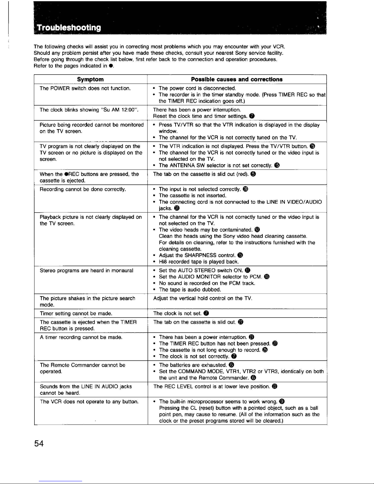
The following checks will assist you
in
correcting most problems which you
may
encounter with your
VCR.
Should any problem persist after you have made these checks, consult your nearest Sony service facility.
Before going through the check list below, first refer back to the connection and operation procedures.
Refer to the pages indicated
in
e.
Symptom
Possible causes and corrections
The
POWER
switch does not function. • The power cord
is
disconnected.
• The recorder
is
in
the timer standby mode. (Press TIMER
REG
so that
the
TIMER
REG
indication goes off.)
The
clock blinks showing "Su
AM
12:00". There has been a power interruption.
Reset the
clock time and timer settings. 0
Picture being recorded cannot
be
monitored • Press
TV
/VTR so that the VTR indication
is
displayed
in
the display
on
the
TV
screen. window.
• The channel for the
VCR
is
not correctly tuned
on
the
TV.
TV
program
is
not clearly displayed
on
the • The VTR indication
is
not displayed. Press the TV /VTR button.
~
TV
screen or no picture
is
displayed on the • The channel for the
VCR
is
not correctly tuned or the video input
is
screen. not selected on the
TV.
• The ANTENNA
SW
selector
is
not set correctly.
~
When the
eREC
buttons are pressed, the The tab on the cassette
is
slid out (red). 0
cassette
is
ejected.
Recording cannot
be
done correctly.
• The input
is
not selected correctly.
@i)
• The cassette
is
not inserted.
• The connecting cord
is
not connected to the
LINE
IN
VIDEO/ AUDIO
jacks.
@1)
Playback picture
is
not clearly displayed
on
• The channel for the
VCR
is
not correctly tuned or the video input
is
the TV screen.
not
selected on the
TV.
• The video heads may be contaminated.
@)
Clean the heads using the Sony video head cleaning cassette.
For
details
on
cleaning, refer to the instructions furnished with the
cleaning cassette.
• Adjust the SHARPNESS control.
~
•
HiS
recorded tape
is
played back.
Stereo programs are heard
in
monaural • Set the AUTO STEREO switch ON.
4D
• Set the AUDIO MONITOR selector to
PCM.
~
.
No
sound
is
recorded
on
the
PCM
track .
• The tape
is
audio dubbed.
The picture shakes
in
the picture search Adjust the vertical hold control
on
the
TV.
mode.
Timer setting cannot
be
made.
The
clock
is
not set. 0
The cassette
is
ejected when the TIMER The tab on the cassette
is
slid out. fl)
REG
button
is
pressed.
A timer recording cannot
be
made. • There has been a power interruption. fl)
• The TIMER
REG
button has not been pressed.
fl)
• The cassette
is
not long enough to record.
fi
• The clock
is
not set correctly. 0
The Remote Commander cannot
be
• The batteries are exhausted.
CD
operated.
.
Set the COMMAND
MODE,
VTR1, VTR2 or VTR3, identically
on
both
the unit and the Remote Commander.
CD
Sounds from the
LINE
IN
AUDIO jacks
The
REG
LEVEL control
is
at lower leve position. 0
cannot
be
heard.
The
VCR
does not operate to any button. • The built-in microprocessor seems to work wrong. 0
Pressing the
CL
(reset) button with a pointed object, such as a ball
point pen, may cause to resume. (All of the information such as the
clock or the preset programs stored will
be
cleared.)
54
I
I
Notes
on
Video Heads
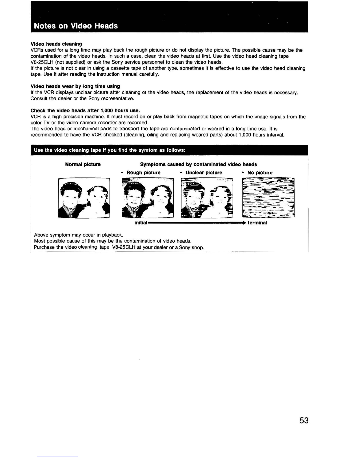
Video heads cleaning
VCRs used for a long time may play back the rough pjcture or do not display the picture. The possible cause may
be
the
contamination of the video heads.
In
such a case, clean the video heads at first. Use the video head cleaning tape
V8-25CLH (not supplied) or ask the Sony service personnel to clean the video heads.
If the picture
is
not clear
in
using a cassette tape of another type, sometimes it is effective
to
use the video head cleaning
tape.
Use
it after reading the instruction manual carefully.
Video heads wear by long time using
If the
VCR
displays unclear picture after cleaning of the video heads, the replacement of the video heads
is
necessary.
Consult the dealer or the Sony representative.
Check the video heads after 1,000 hours use.
VCR
is
a high precision machine. It must record on or play back from magnetic tapes on which the image signals from the
color
TV
or the video camera recorder are recorded.
The video head or mechanical parts to transport the tape are contaminated or weared
in
a long time use. It
is
recommended
to
have the
VCR
checked (cleaning, oiling and replacing weared parts) about 1,000 hours interval.
Use the video cleaning tape if you find the symtom
as
follows:
Normal picture
Symptoms caused by contaminated video heads
Above symptom may occur in playback.
Most possible cause of this may
be the contamination of video heads.
Purchase the video cleaning tape
V8-25CLH at your dealer
or
a Sony shop.
• No picture
53
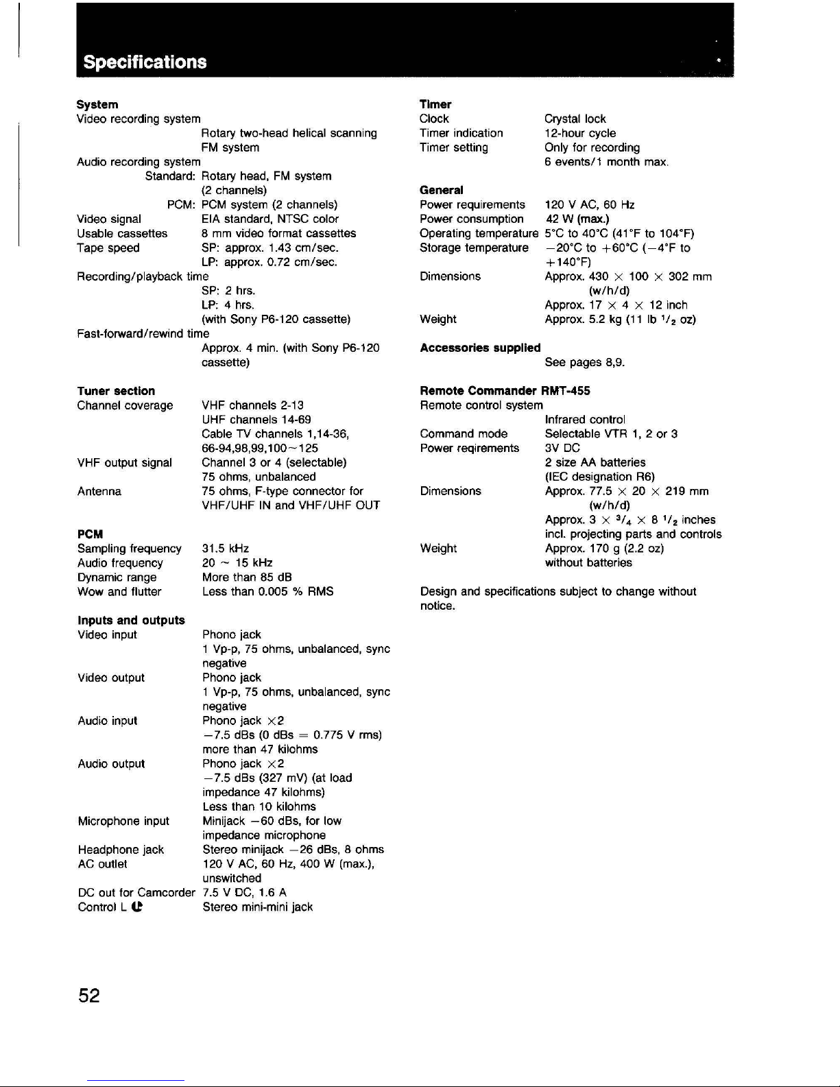
Specifications ·
System
Video recording system
Audio recording system
Rotary two-head
helical scanning
FM
system
Standard: Rotary head,
FM
system
{2
channels)
Video signal
Usable
cassettes
Tape speed
PCM:
PCM
system
{2
channels)
EIA
standard, NTSC color
8
mm
video format cassettes
SP:
approx. 1.43 em/sec.
LP:
approx.
0.
72
em/sec.
Recording/playback time
SP:
2 hrs.
LP:
4 hrs.
(with
Sony P6-120 cassette)
Fast-forward/rewind time
Tuner section
Channel coverage
VHF output signal
Antenna
PCM
Sampling frequency
Audio frequency
Dynamic range
Wow and
flutter
Inputs and outputs
Video input
Video output
Audio input
Audio output
Microphone input
Headphone jack
AC
outlet
DC
out for Camcorder
Control L
(t
52
Approx. 4
min.
(with Sony P6-120
cassette)
VHF channels 2-13
UHF
channels 14-69
Cable TV channels 1,14-36,
66-94,98,99,1
00-125
Channel 3 or 4 (selectable)
75
ohms, unbalanced
75
ohms, F-type connector tor
VHF/UHF
IN
and VHF/UHF OUT
31.5 kHz
20-15kHz
More than
85
dB
Less than 0.005 %
RMS
Phonojack
1
Vp-p,
75
ohms, unbalanced, sync
negative
Phonojack
1
Vp-p,
75
ohms, unbalanced, sync
negative
Phono jack
x 2
-7.5
dBs
(0
dBs = 0.775 V
rms)
more than
47
kilohms
Phono jack x 2
-7.5
dBs {327
mV)
{at load
impedance
47
kilohms)
Less than 1 o kilohms
Minijack
-60
dBs, for low
impedance microphone
Stereo minijack
-26
dBs, 8 ohms
120 V
AC,
60
Hz,
400 W (max.),
unswitched
7.5 V DC,
1.6 A
Stereo mini-mini jack
Timer
Clock
Timer indication
Timer setting
General
Crystal lock
12-hour cycle
Only
tor recording
6 events/1 month
max.
Power requirements 120 V
AC,
60
Hz
Power consumption
42
W {max.)
Operating temperature
soc to
40oC
(41oF
to 104°F)
Storage temperature
-20°C
to
+60°C
(-4°F
to
+140°F)
Dimensions Approx. 430 X 1 00 X 302
mm
(w/h/d)
Approx. 17 X 4 X
12
inch
Weight Approx. 5.2
kg
(11
lb
1
/
2
oz)
Accessories supplied
See pages 8,9.
Remote Commander RMT-455
Remote control system
Infrared control
Command mode Selectable
VTR
1,
2 or 3
Power reqirements
3V
DC
Dimensions
Weight
2 size
AA
batteries
(IEC
designation
R6)
Approx. 77.5 X 20 X 219
mm
(w/h/d)
Approx. 3 X
3
/
4
X 8
1
/
2
inches
incl. projecting parts and controls
Approx. 170 g
(2.2
oz)
without batteries
Design and specifications subject to change without
notice.
Precautions
On safety
• Operate
the unit only on 120 V
AC.
• Should any solid object or liquid fall into the cabinet,
unplug the unit and have it checked by qualified
personnel before operating it any further.
• One blade
of
the plug is wider than the other for the
purpose
of
safety and will fit into the power outlet only
one way. If you are unable
to
insert the plug fully into
the outlet, contact your dealer.
• Unplug the unit from the wall outlet if it is not to be
used for an extended period of time. To disconnect the
cord, pull it out by the
plug. Never pull the cord itself.
On Installation
•
Allow adequate air circulation to prevent internal heat
build-up. Do not cover the holes on the top
panel.
•
Do
not place the unit
on
surfaces (rugs, blankets,etc.)
or
near materials (curtains, draperies) that may block the
ventilation slots.
• Do not install the unit near heat sources such as
radiators or air ducts
or
in
a place subject to direct
sunlight,excessive dust, mechanical vibration or shock.
• The unit is designed for operation
in
a horizontal
position. Do not install it
in
an inclined position .
• Keep the unit and cassette tapes away from equipment
with strong magnets, as for example a microwave oven
or a large loudspeaker and so on.
•
Do
not place any heavy object on the unit.
Never place any object on the tuning compartment nor
on
the top of the front panel.
On
operation
•
When the unit is not in use, turn the power
oH
to
conserve energy and to extend its useful life.
• Remove and store a video cassette after recording
or
playback.
On cleaning
Clean
the cabinet, panel and controls with a
dry
soft cloth,
or a soft cloth
lightly moistened with a mild detergent
solution.
Do not use any type of solvent, such as
alcohol or
benzine which might damage the finish.
On
f4!Pl!Cklng
Do not throw away the carton and packing materials.
They make an ideal container
in
which to transport the
unit. When shipping the unit to another location, repack it
as shown the illustration on the carton.
On cassette care
Store cassettes
in
their cases and keep them
in
an upright
position to prevent intrusion of dust and uneven winding.
On
moisture condensation
•
Main Unit
Do not operate the unit right after having transported it
from a
cold location to a warm location
or
in
a room
where the temperature rises suddenly, because moisture
may condense
in
the operating section of the unit. Wait
for about an hour before turning the power on in the
new location or keep the rise
in
room temperature
gradual. If the unit is operated with moisture
condensation, the unit and the tape may be damaged.
Therefore remove the tape immediately when there is a
possibility
of
moisture condensation and no picture
is
obtained. To evaporate the moisture rapidly, leave the
player turned on without a tape loaded.
• Cassette
When a cassette tape is carried from a cold place to a
warm place, the cassette tape may become wet with
dew created by moisture condensation. When there is
any possibility of moisture condensation, eject the
cassette tape and leave it outside of the compartment
for about one hour.
If you have any questions about this unit,contact your
Sony dealer.
51
Presetting
TV
channels
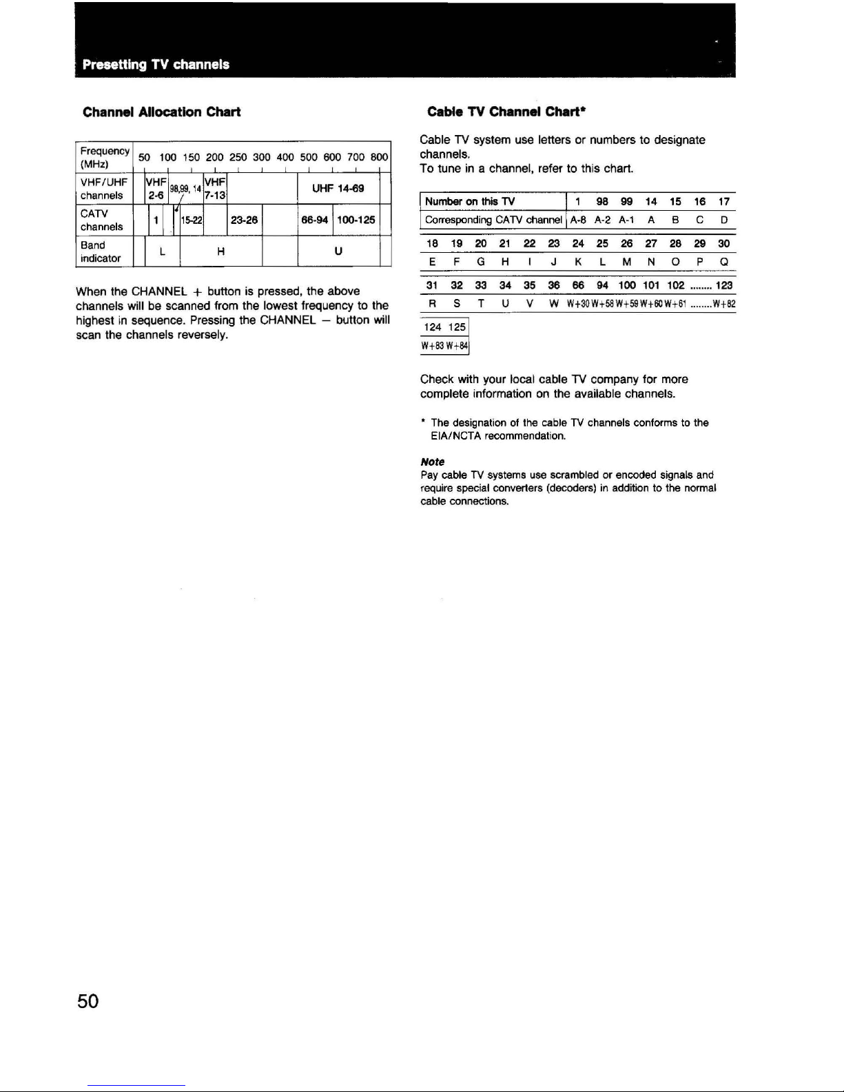
Channel Allocation Chart
Frequency
50
100
150 200 250 300 400 500 600 700 800
(MHz)
VHF/UHF
IVH~I
!vHF
UHF 14-69
channels
2·6
98,99,
14
7-13
CATV
11
J
15-22
23-26
66·9411()().125
channels
Band
J
L
H
u
indicator
When
the
CHANNEL + button
is
pressed,
the
above
channels
will
be
scanned
from
the
lowest
frequency
to
the
highest
in
sequence
. Pressing
the
CHANNEL -button
will
scan
the
channels
reversely.
50
Cable
TV
Channel
Chart•
Cable
TV
system
use
letters
or
numbers
to
designate
channels.
To
tune
in a
channel,
refer
to this chart.
Number on
this TV
96
99 14 15 16 17
Corresponding
CATV
channel
A-8 A-2
A-1
A 8 c D
18 19
20
21
22
23
24 25 26 27 28 29
30
E F G H K L M N 0
p
Q
31
32 33
34
35
36 66
94
100
101
102 ........ 123
R s T u v w
Wt30W
t58 Wt
59
Wtli0W
t 61
Check
with
your
local
cable
TV
company
for
more
complete
information
on
the
available
channels.
........
Wt82
• The designation of the cable TV channels conforms to the
EIA/NCTA recommendation.
Note
Pay
cable
TV
systems use scrambled or encoded signals and
require special converters (decoders)
in
addition to
the
normal
cable connections.
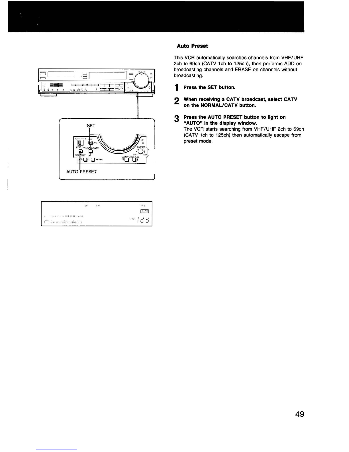
SET
AUTO RESET
I
.........
.
;:;
'"'
....
,.,_
,.,-p,j.,,l-lll
Auto Preset
This
VCR
automatically searches channels from VHF/UHF
2ch to 69ch (CATV 1 ch to 125ch), then performs ADD
on
broadcasting channels and ERASE on channels without
broadcasting.
1 Press the
SET
button.
2 When receiving a CATV broadcast, select CATV
on the
NORMAL/CATV button.
3 Press the AUTO
PRESET
button
to
light on
"AUTO" in the display window.
The VCR starts searching from VHF/ UHF 2ch to 69ch
(CATV 1ch to 125ch) then
automatically escape from
preset mode.
49
Presetting TV Channels
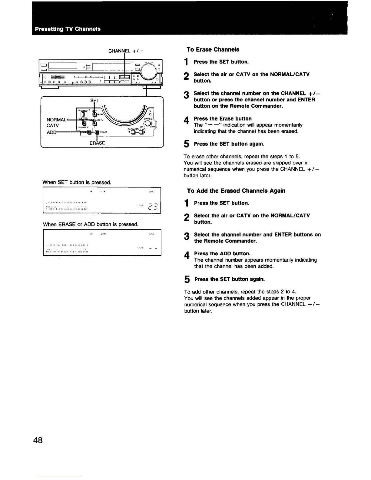
CHANNEL
+1-
NOR
MALI-+"~~
CATV
AD0---~~~
~ _ _2Q::g_;:
~
When
SET
button is pressed.
I·
···
............
. .
l'
oiH"I'"I
IIO»I·W>II-II'U•IU 'ii' '
IIO
I
When
ERASE
or ADD button
is
pressed.
I .
•
I~
~
If'
II
M'
~I
• I •
Ml
Mo
HI
U'
HI
Ill
0
..
-~-
U ,I
'IIjl
II•
p,n:
.u.
IOioll·ll
IIIIH--111-111
48
To
Erase Channels
1 Press the SET button.
2 Select
the
air
or
CATV on
the
NORMAL/CATV
button.
3 Select
the
channel number on
the
CHANNEL+/-
button
or
press
the
channel number and ENTER
button
on
the
Remote Commander.
4 Press
the
Erase
button
The"--"
indication will appear momentarily
indicating that the channel has been erased.
5 Press
the
SET
button
again.
To erase other channels, repeat the steps 1 to
5.
You will see the channels erased are skipped over
in
numerical sequence when
you
press the CHANNEL +
/-
button later.
To Add the Erased Channels Again
1 Press
the
SET
button
.
2 Select
the
air
or
CATV on
the
NORMAL/CATV
button.
3 Select the channel
number
and
ENTER
buttons
on
the
Remote Commander.
4 Press the ADD button.
The
channel number appears momentarily indicating
that the
channel has been added.
5 Press the SET
button
again.
To
add
other channels, repeat the steps 2 to
4.
You
will
see
the channels added appear
in
the proper
numerical sequence when
you
press the CHANNEL + /-
button later.
Presetting TV Channels
1-0
-
ENTER
l~gg
olQJI
~
~
TI!.IEASET·F'ULLOI'EN
ODD
1998
ooo
' . '
9~/ffi
DOD
'CiD:a:J
oi3J0
!;,?
s
~·=
IBC::J
•u~
"'w
0 "
~'"'"
[5'
w -
DOD
ooa
D
\..
_,)
c
~
I
===
$ s
·$
0 J
CJ=r:::J
f--
SET
CHANNEL
+I-
NORMAL/CATV
--CHANNEL-+
I II I
'
'"
,-,
,-,
,-1
J-1
,-,
UH
UUM
UUs
:
::!JCJ
1:_
1
3
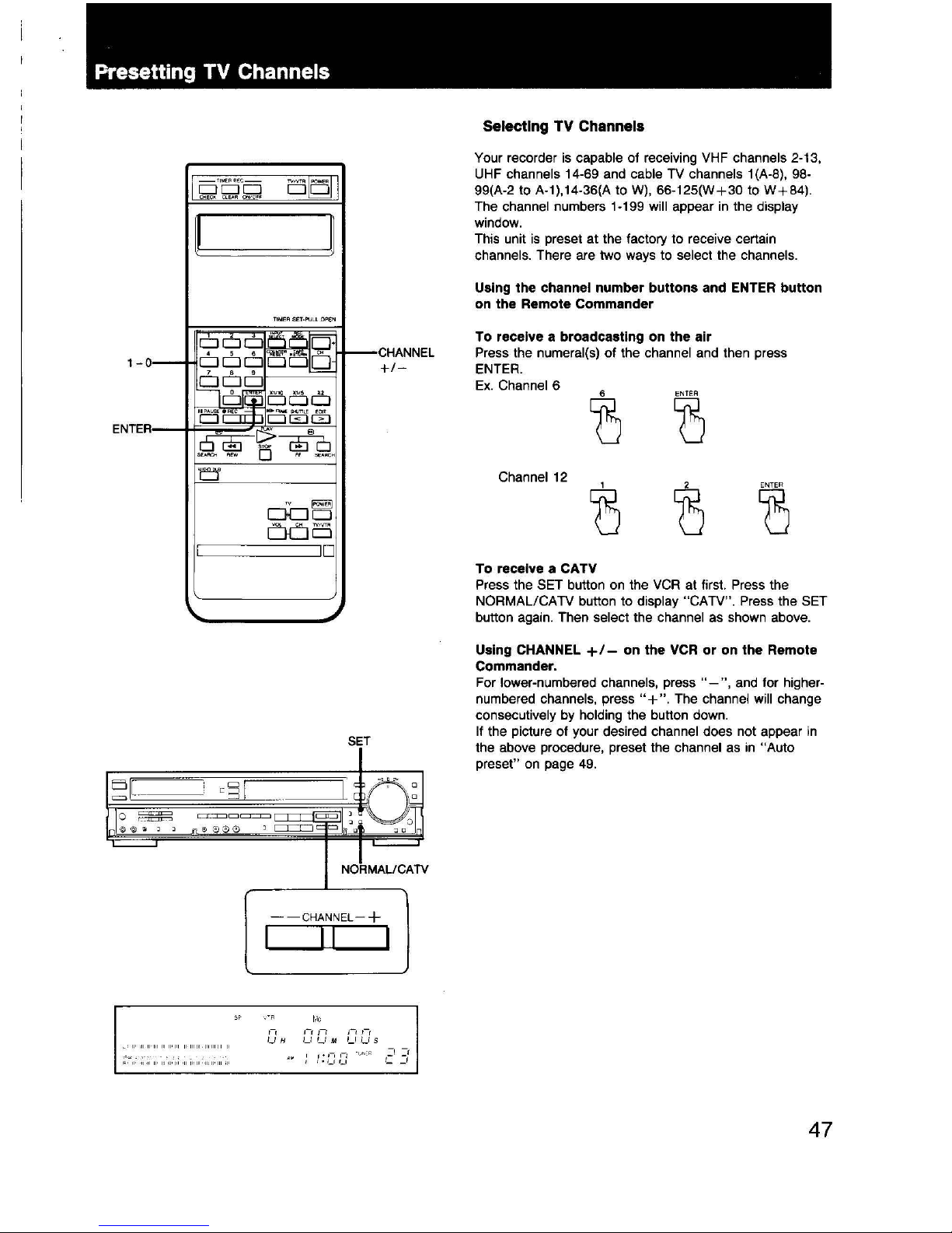
Selecting TV Channels
Your recorder
is
capable of receiving
VHF
channels 2-13,
UHF
channels 14-69 and cable TV channels 1 (A-8),
98-
99(A-2 to A-1),14-36(A
toW),
66-125(W+30 to
W+84).
The channel numbers 1-199 will appear
in
the display
window.
This unit
is
preset at the factory to receive certain
channels. There
are
two ways to select the channels.
Using
the
channel number
buttons
and ENTER
button
on the Remote Commander
To receive a broadcasting on
the
air
Press the numeral(s) of the channel and then press
ENTER.
Ex.
Channel 6
6
ENTER
CJ
CJ
Channel
12
1 2
ENTER
0 0
0
To
receive a CATV
Press the SET button on the
VCR
at first. Press the
NORMAL/CATV button to
display "CATV". Press the SET
button again. Then
select the channel
as
shown above.
Using
CHANNEL
+1-
on
the
VCR
or
on
the
Remote
Commander.
For lower-numbered channels,
press"-",
and
for higher-
numbered channels, press
"+
". The channel will change
consecutively
by
holding the button down.
If
the picture of your desired channel does not appear
in
the above procedure, preset the channel
as
in
"Auto
preset"
on
page
49.
47
Adjusting the
TV
<
POYER
46
I>
PLAY
3CH
riil
4CHl£j
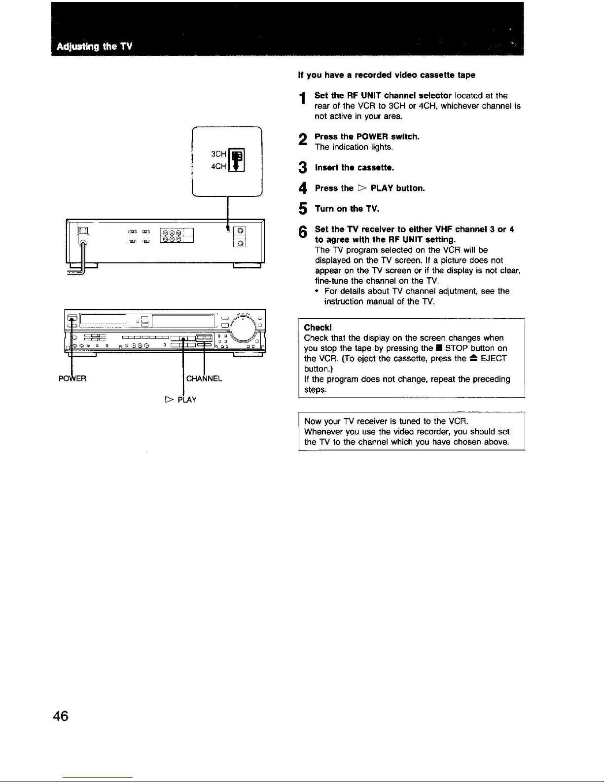
If you have a recorded video cassette tape
1 Set the
RF
UNIT channel selector located
at
the
rear
of
the VCR to 3CH or 4CH, whichever channel is
not
active in your area.
2 Press the POWER switch.
The indication lights.
3
4
5
Insert the cassette.
Press the
I>
PLAY button.
Turn on the TV.
6 Set the TV receiver to either VHF channel 3 or 4
to agree with the
RF
UNIT setting.
The TV program selected on the VCR will be
displayed on the TV screen. If a picture does not
appear on the TV screen or if the
display is not clear,
fine-tune the channel on the TV.
• For details about TV channel adjutment, see the
instruction manual
of
the TV.
Checkl
Check that the display on the screen changes when
you stop the tape by pressing the
• STOP button on
the
VCR. (To eject the cassette, press the
;::=:;
EJECT
button.)
If the program
does
not
change, repeat the preceding
steps.
Now
your TV receiver is tuned
to
the VCR.
Whenever you use the video recorder, you should set
the TV
to
the channel which you have chosen above.
'
I
I
Adjusting the
TV
INPUT SELECT
ANT
TV/VTR
3CH~
4CHliJ
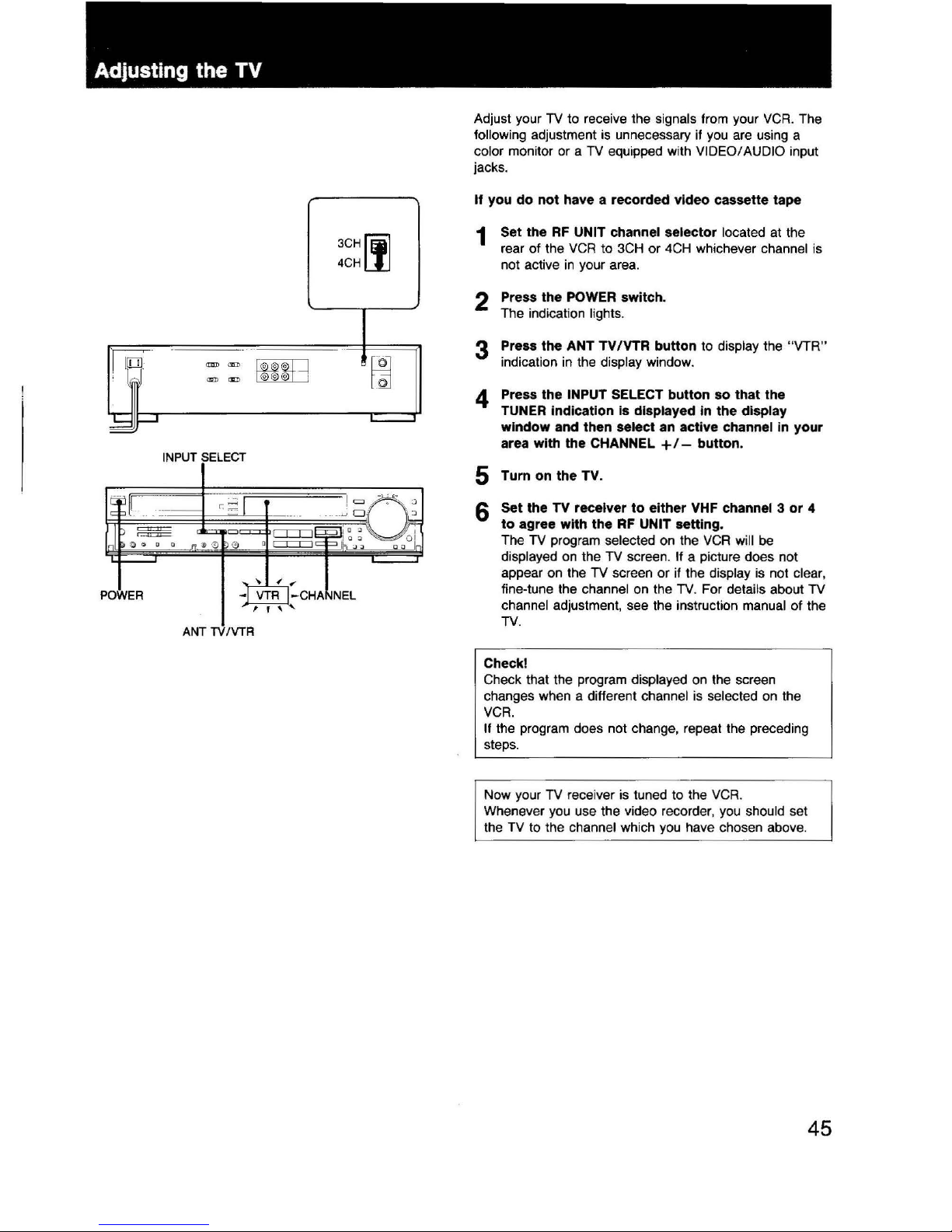
Adjust your
TV
to receive the signals from your
VCR
. The
following adjustment
is
unnecessary if
you
are using a
color monitor or a
TV
equipped with VIDEO/ AUDIO input
jacks.
If you do not have a recorded video cassette tape
1 Set the
RF
UNIT channel selector located at the
rear of the
VCR
to
3CH
or
4CH
whichever channel
is
not active
in
your area.
2 Press the POWER switch.
The indication
lights.
3 Press the ANT
TV/VTR
button
to
display the "VTR"
indication
in
the display window.
4 Press the INPUT SELECT button so that the
TUNER
Indication
is
displayed
In
the display
window and then select an active channel
in
your
area with the CHANNEL
+1- button.
5 Turn
on
the TV.
6
Set the TV receiver to either VHF channel 3 or 4
to agree with the
RF
UNIT setting.
The
TV
program selected on the
VCR
will
be
di
splayed on the
TV
screen. If a picture does not
appear on the TV screen or if the
display
is
not clear,
fine-tune the channel on the TV. For details about TV
channel adjustment, see the instruction manual of the
TV.
Check!
Check that the program displayed on the screen
changes when a different
channel is selected
on
the
VCR.
If the program does not change, repeat the preceding
steps.
Now your TV receiver
is
tuned to the
VCR
.
Whenever you use the video recorder, you should set
the
TV
to th
e channel whi
ch
you
have chosen above.
45
Connections
44
TAPE
IN
or
AUXIN
~
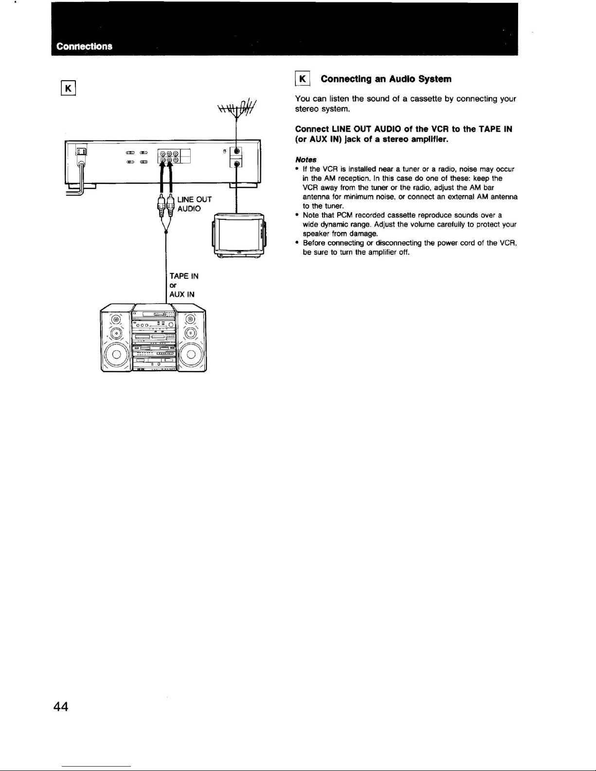
Connecting an Audio System
You can listen the sound of a cassette by connecting your
stereo system.
Connect LINE OUT AUDIO of the
VCR
to the TAPE
IN
(or AUX IN) jack of a stereo amplifier.
Notes
• If the
VCR
is installed near a tuner or a radio, noise may occur
in
the
AM
reception. In this case
do
one of these: keep the
VCR
away from the tuner
or
the radio, adjust the
AM
bar
antenna for
minimum
noise, or
connect
an
external
AM
antenna
to the tuner.
• Note that
PCM
recorded cassette reproduce sounds over a
wide dynamic range. Adjust the volume carefully to protect your
speaker from damage.
• Before connecti
ng
or disconnecting the power cord of the
VCR
,
be sure to turn the amplifier off.
3
VIDEO/AUDIO
INPUT
0
VIDEO/AUDIO
INPUT
0
1
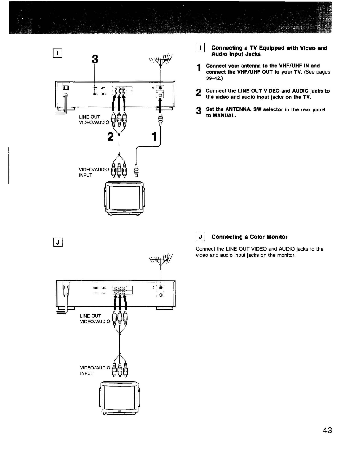
[!]
Connecting a TV Equipped
with
VIdeo and
Audio
Input Jacks
1 Connect
your
antenna
to
the
VHF/UHF
IN
and
connect
the VHF/UHF OUT
to
your
TV.
(See
pages
39-42
.)
2 Connect the LINE OUT VIDEO and AUDIO jacks
to
the
video
and audio Input jacks
on
the TV.
3 Set the ANTENNA. SW
selector
in
the
rear panel
to
MANUAL
QJ
Connecting a Color Monitor
Connect the
LINE
OUT VIDEO
and
AUDIO jacks to the
video and audio input jacks on the monitor.
43
ConnectiOns
42
1
VHF/UHF
IN
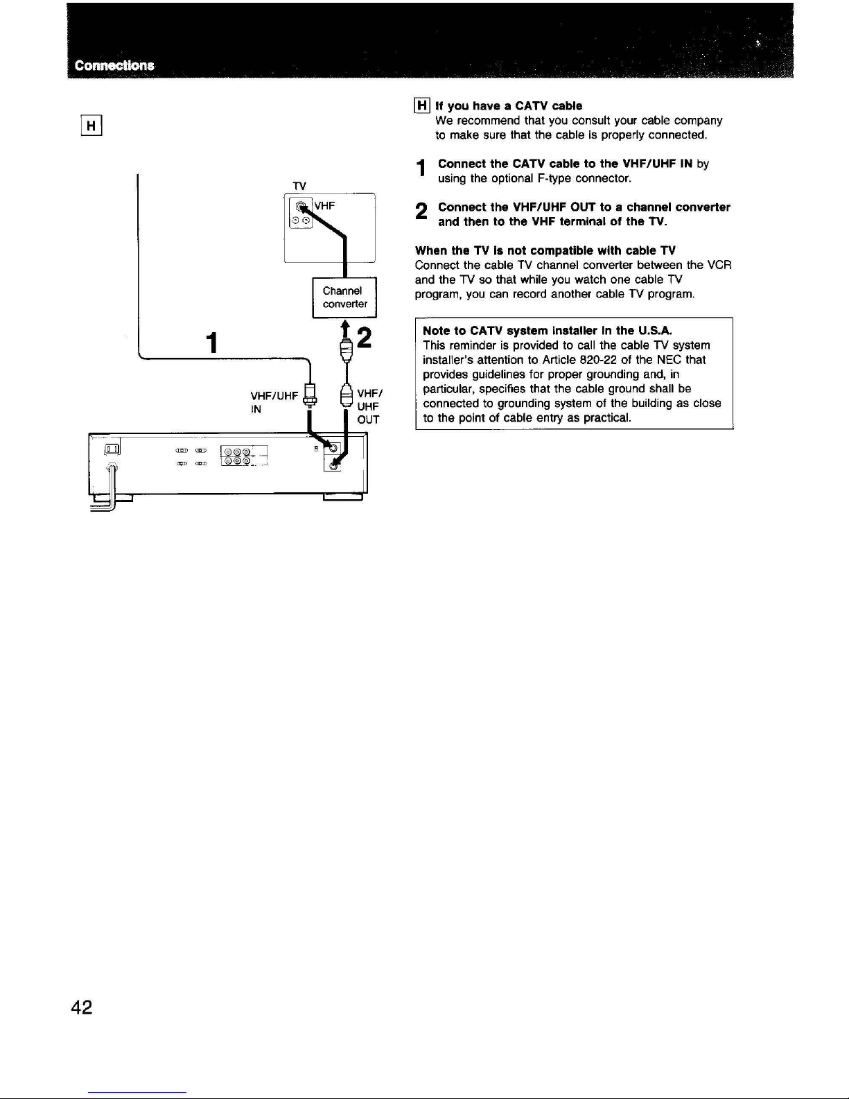
[HJif
you
have a CATV cable
We
recommend that you consult your cable company
to make sure that the cable
is
properly connected.
1 Connect the CATV cable to the VHF/UHF
IN
by
using the optional F-type connector.
2 Connect the VHF/UHF OUT to a channel converter
and
then to the
VHF
terminal of the TV.
When
the TV
Is
not compatible with cable TV
Connect the cable TV channel converter between the
VCR
and the TV so that while you watch one cable
TV
program, you can record another cable TV program.
Note to CATV system installer
In
the
U.S.A.
This reminder
is
provided to call the cable
TV
system
installer's attention to Article 820-22 of the
NEC
that
provides guidelines for proper grounding and,
in
particular, specifies that the cable ground shall
be
connected to grounding system of the building as close
to the point of cable entry as practical.
•
1
UHF
VHF
1
VHF/UHF
IN
TV
~
UHF
LJ--t--J
~
2
~
'""
9 UHF
~
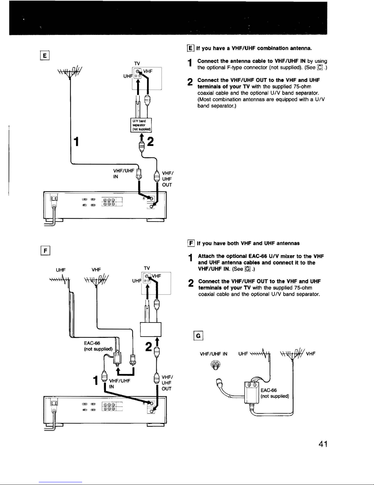
If
you have a VHF/UHF combination antenna.
1 Connect
the
antenna cable
to
VHF/UHF
IN
by
using
the
optional F-type connector (not supplied). (See ~ .)
2 Connect
the
VHF/UHF OUT
to
the
VHF and
UHF
terminals
of
your
TV with the supplied 75-ohm
coaxial
cable
and
the optional
UIV
band
separator.
(Most combination antennas are equipped with a
UIV
band separator.)
[f]
If
you
have
both
VHF and UHF antennas
1 Attach
the
optional EAC-66
U/V
mixer
to
the
VHF
and UHF antenna cables and connect
It
to
the
VHF/UHF
IN.
(See~.)
2 Connect
the
VHF/UHF OUT
to
the
VHF
and
UHF
terminals
of
your
TV with the supplied 75-ohm
coaxial
cable
and
the optional
UIV
band
separator.
VHF/UHF
IN
\
41
.
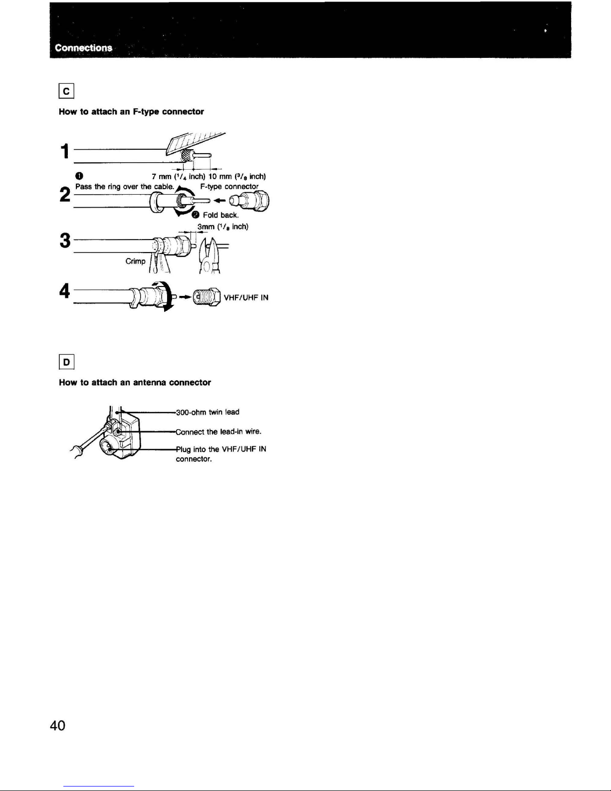
Connections
How to attach an F-type connector
1~
.1
l
I.
Q 7
mm
(
1
/
4
inch)
10
mm
(>/
0
inch)
2
Pass
the ring over the
fle.~ty:c
~
• Fold back.
3
~
·
·,·
.··., '
~
..
300fm~(',,lnch)
·.
'·
_.
. ' I
,,
I
Crimp
\\
()
.
\\
~
\,
· I
4~--VHF/UHFIN
How to attach an antenna connector
'\al\r1H-;I-----Piug
into the VHF/UHF
IN
connector.
40
Connections
2
TV
UHF
VHF/UHF
IN
1
1
; I
I
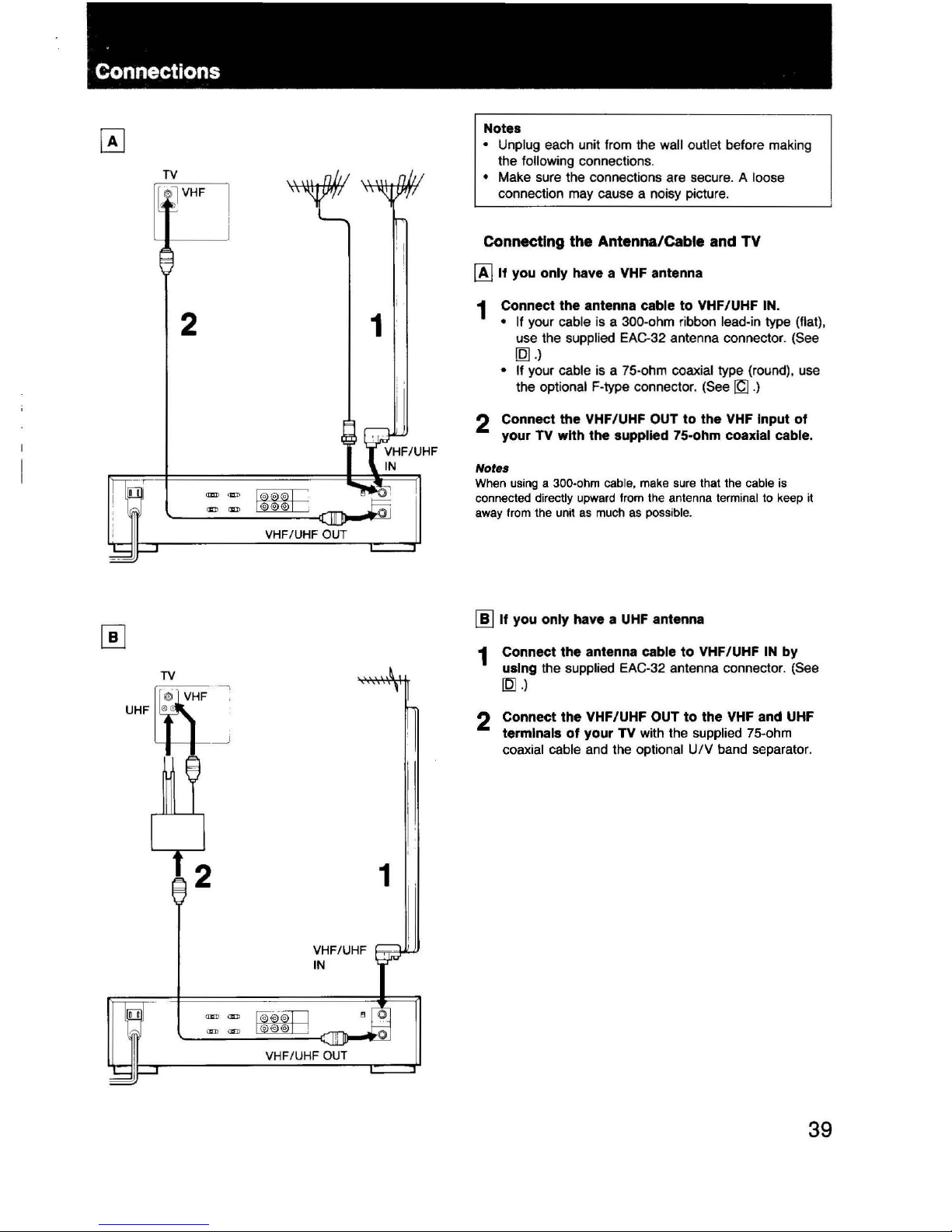
Notes
• Unplug each unit from the wall outlet before making
the
following connections.
• Make sure the connections are secure. A loose
connection may cause a noisy picture.
Connecting the Antenna/Cable and TV
[A]
If you only have a VHF antenna
1 Connect the antenna cable to VHF/UHF IN.
• If
your cable
is
a 300-ohm ribbon lead-in type (flat),
use the supplied EAC-32 antenna connector. (See
[Q]
.)
• If your cable
is
a 75-ohm coaxial type (round), use
the optional F-type connector. (See
~
.)
2 Connect the VHF/UHF OUT to the VHF Input of
your
TV with the supplied 75-ohm coaxial cable.
Notes
When using a 300-ohm cable, make sure that the cable is
connected
directly upward from the antenna terminal to keep it
away from the unit as much as possible.
[ID
If you only have a
UHF
antenna
1 Connect the antenna cable to VHF/UHF
IN
by
using the supplied EAC-32 antenna connector. (See
[Q]
.)
2 Connect the VHF/UHF OUT to the VHF and UHF
terminals of your TV with the supplied 75-ohm
coaxial cable and the optional
UIV
band separator.
39
 Loading...