

DSX-A30/A30E
SERVICE MANUAL
Ver. 1.4 2012.11
Photo: DSX-A30
• This model is not equipped with a mechanism deck.
SPECIFICATIONS
Tuner section
(E, Mexican, Aregentina and Indian models) (Saudi Arabia model) (AEP, Russian and UK models)
FM
FM
Tuning range:
For non-Argentine models:
87.5 – 108.0 MHz (at 50 kHz step)
108.0 MHz (at 100 kHz step)
87.5 –
87.5 – 107.9 MHz (at 200 kHz step)
For Argentine models:
87.5 – 107.9 MHz
FM tuning step (for non-Argenti ne models):
50 kHz/100 kHz/200 kHz switchable
Antenna (aerial) terminal:
External antenna (aerial) conne ctor
Intermediate frequency: 25 kHz
Usable sensitivity: 8 dBf
Selectivity: 75 dB at 400 kHz
Signal-to-noise ratio: 80 dB (stereo)
Separation: 50 dB at 1 kHz
Frequency response: 20 – 15,000 Hz
AM
Tuning range:
For non-Argentine models:
531 – 1,602 kHz (at 9 kHz step)
530 – 1,710 kHz (at 10 kHz ste
For Argentine models:
530 – 1,710 kHz
AM tuning step (for non-Argentine models):
9 kHz/10 kHz switchable
Antenna (aerial) terminal:
External antenna (aerial) connec tor
Intermediate frequency:
For non-Argentine models:
9,124.5 kHz or 9,115.5 kHz/4.5 kHz
(at 9 kHz step)
9,115 kHz or 9,125 kHz/5 kHz (at 10 kHz step)
For Argentine models:
9,115 kHz or 9,125 kHz/5 kHz
Sensitivity: 26 μV
p)
Tuner section
FM
Tuning range: 87.5 – 108.0 MHz
Antenna (aerial) terminal:
External antenna (aerial) conne ctor
Intermediate frequency: 25 kHz
Usable sensitivity: 8 dBf
Selectivity: 75 dB at 400 kHz
Signal-to-noise ratio : 80 dB (stereo)
Separation: 50 dB at 1 kHz
response: 20 – 15,000 Hz
Frequency
MW
Tuning range: 531 – 1,602 kHz
Antenna (aerial) terminal:
External antenna (aerial) conne ctor
Intermediate frequency:
9,124.5 kHz or 9,115.5 kHz/4.5 kHz
Sensitivity: 26 μV
SW
Tuning range:
SW1: 2,940 – 7,735 kHz
SW2: 9,500 – 18,135 kHz
(except for 10,140 – 11,575 kHz)
Antenna (aerial) terminal:
External antenna (aerial) connec tor
Intermediate frequency:
9,124.5 kHz or 9,115.5 kHz/4.5 kHz
Sensitivity: 26 μV
Тuner section
FM
FM
Tuning range:
DSX-A30E
FM1/FM2: 87.5 – 108.0 MHz (50 kHz step)
FM3: 65 – 74 MHz (30 kHz step)
DSX-A30
Tuning range: 87.5 – 108.0 MHz
nna (aerial) terminal:
Ante
External antenna (aerial) conne ctor
Intermediate frequency: 25 kHz
Usable sensitivity: 8 dBf
Selectivity: 75 dB at 400 kHz
Signal-to-noise ratio : 80 dB (stereo)
Separation: 50 dB at 1 kHz
Frequency response: 20 – 15,000 Hz
MW/LW
Tuning range:
MW: 531 – 1,602 kHz
LW: 153 – 279 kHz
Antenna (aerial) terminal:
External antenna (aerial) connec tor
Intermediate frequency:
9,124.5 kHz or 9,115.5 kHz/4.5 kHz
Sensitivity: MW: 26 μV, LW: 45 μV
USB Player section
Interface: USB (Full-speed)
Maximum current: 500 mA
AEP Model
UK Model
E Model
DSX-A30
Russian Model
DSX-A30/A30E
Power amplier section
Output: Speaker outputs
Speaker impedance: 4 – 8 ohms
Maximum power output: 50 W × 4 (at 4 ohm s)
General
Outputs:
Audio outputs terminal (rear)
AEP, Russian and UK models:
Power antenna (aerial) relay control terminal
Power amplier control terminal
E, Saudi Arabia, Mexican, Argentina and Indian models:
Power antenna (aerial)/Power amplier control
terminal (REM OUT)
Inputs:
Remote controller input terminal
Antenna (aerial) input terminal
AUX input jack (stereo mini jack)
USB signal input connector
Power requirements: 12 V DC car batt ery
(negative grou nd (earth))
Dimensions: Approx. 178 × 50 × 120 mm
1
/8 × 2 × 47/8 in) (w/h/d)
(7
Mounting dimensions: Approx. 182 × 53 × 103 mm
1
/4 × 21/8 × 41/8 in) (w/h/d)
(7
Mass: Approx. 0.7 kg (1 lb 9 oz)
Supplied accessori es:
Remote commander: RM-X211
Parts for installation and connections (1 set)
Design and specications are subject to change
without notice.
E, Mexican, Argentina, Indian models
9-893-394-05
2012K33-1
2012.11
©
FM/AM DIGITAL MEDIA PLAYER
Saudi Arabia model
FM/MW/SW DIGITAL MEDIA PLAYER
AEP, Russian, UK models
FM/MW/LW DIGITAL MEDIA PLAYER
Sony Corporation
Published by Sony Techno Create Corporation

DSX-A30/A30E
Ver. 1.2
Windows Media is either a registered
trademark or trademark of Microso
Corporation in the United States and/or
other countries.
is product contains technology subject
to certain intellectual property rights of
Microso. Use or distribution of this
technology outside of this product is
prohibited without the appropriate
license(s) from Microso.
MPEG Layer-3 audio coding technology
and patents licensed from Fraunhofer IIS
and omson.
TABLE OF CONTENTS
1. SERVICING NOTES ............................................. 3
2. GENERAL .................................................................. 4
3. DISASSEMBLY
3-1. Disassembly Flow ........................................................... 7
3-2. Fuse (Blade Type) (Auto Fuse) (10A/32V) (FU101),
Cover ............................................................................... 7
3-3. Sub Panel Block .............................................................. 7
3-4. MAIN Board ................................................................... 7
4. DIAGRAMS
4-1. Block Diagram - MAIN Section - ................................... 8
4-2. Block Diagram
- DISPLAY/POWER SUPPLY Section - ........................ 9
4-3. Schematic Diagram - MAIN Board (1/3) - ..................... 11
4-4. Schematic Diagram - MAIN Board (2/3) - ..................... 12
4-5. Schematic Diagram - MAIN Board (3/3) - ..................... 13
4-6. Printed Wiring Board - MAIN Board (Component Side)
(Except Saudi Arabia model) - ........................................ 14
4-7. Printed Wiring Board - MAIN Board (Conductor Side)
(Except Saudi Arabia model) - ........................................ 15
4-8. Printed Wiring Board - MAIN Board (Component Side)
(Saudi Arabia model) - .................................................... 16
4-9. Printed Wiring Board - MAIN Board (Conductor Side)
(Saudi Arabia model) - .................................................... 17
4-10. Printed Wiring Board - KEY Board -.............................. 18
4-11. Schematic Diagram - KEY Board - ................................ 19
5. EXPLODED VIEWS
5-1. Main Section ................................................................... 25
5-2. Front Panel Section ......................................................... 26
6. ELECTRICAL PARTS LIST .............................. 27
Accessories are given in the last of the electrical parts list.
NOTES ON CHIP COMPONENT REPLACEMENT
• Never reuse a disconnected chip component.
• Notice that the minus side of a tantalum capacitor may be damaged by heat.
2
SECTION 1
SERVICING NOTES
DSX-A30/A30E
Ver. 1.4
UNLEADED SOLDER
Boards requiring use of unleaded solder are printed with the leadfree mark (LF) indicating the solder contains no lead.
(Caution: Some printed circuit boards may not come printed with
the lead free mark due to their particular size)
: LEAD FREE MARK
Unleaded solder has the following characteristics.
• Unleaded solder melts at a temperature about 40 °C higher
than ordinary solder.
Ordinary soldering irons can be used but the iron tip has to be
applied to the solder joint for a slightly longer time.
Soldering irons using a temperature regulator should be set to
about 350 °C.
Caution: The printed pattern (copper foil) may peel away if
the heated tip is applied for too long, so be careful!
• Strong viscosity
Unleaded solder is more viscous (sticky, less prone to fl ow)
than ordinary solder so use caution not to let solder bridges
occur such as on IC pins, etc.
• Usable with ordinary solder
It is best to use only unleaded solder but unleaded solder may
also be added to ordinary solder.
Cleaning the connectors
e unit may not function properly if the
connectors between the unit and the front
panel are not clean. In order to prevent this,
detach the front panel and clean the
connectors with a cotton swab. Do not apply
too much force. Otherwise, the connectors
may be damaged.
ABOUT CHECKING THE OPERATION
When checking the operation of this unit, connect a USB device
to this unit.
Refer to the support site written in the operating instruction for the
details about the compatibility of a USB device.
NOTE THE MAIN BOARD OR SYSTEM CONTROLLER
(IC101) REPLACING
When the MAIN board or system controller (IC101) is replaced,
the destination setting is necessary.
1. Destination Setting
Set destination according to the procedure below.
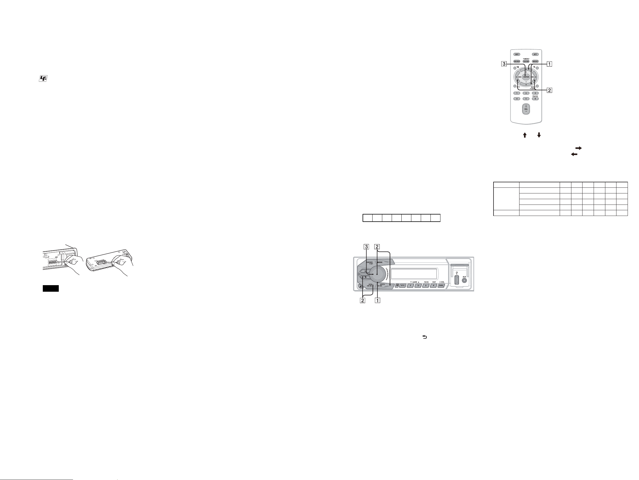
1-1. Setting the Destination Code
1. In the state of source off (the clock is displayed), enter the
test mode by pressing the buttons on the remote commander in
order of the [4] t [5] t [6] (press only the [6] button for two
seconds).
2. In the state in which the system controller version is displayed
on the liquid crystal display, enter the destination setting mode
by pressing the buttons on the main unit in order of the [SEEK
+] t [SEEK –] t [PUSH ENTER/SELECT].
3. Input the alphanumeric character of 6 digits of “F XXXXXX”
displayed on the liquid crystal display, and execute the destination setting.
Note: Refer to following “1-3. Entering the Destination Code” for opera-
tion method.
4. The resetting operation is executed by pressing the [SOURCE/
OFF] button for 1 second after the setting ends, and the unit
returns to the normal condition.
1-2. Display in Destination Setting Mode
OP0OP2OP1OP3OP4OP5
8 digits
F
XXXXXX
1-3. Entering the Destination Code
• Method of operation by main unit
• Method of operation by remote commander
1. Press the [ ] or [ ] button, and select the alphanumeric character of “0 to F”.
2. The digit advances by pressing the [ ] button.
The digit returns by pressing the [ ] button.
3. The setting is completed by pressing the [ENTER] button, and
the initialization operation is done.
1-4. Destination Code
Model Destination OP5 OP4 OP3 OP2 OP1 OP0
DSX-A30
DSX-A30E Russian 0 0 6 2 0 7
AEP, Russian, UK 0 0 4 2 0 1
E, Mexican, Indian 0 0 4 A 0 0
Saudi Arabia 0 0 4 A 0 4
Argentina 0 0 4 A 0 3
2. Confi rmation After Destination Setting
Execute the following operation after completing the destination
setting, and confi rm a correct destination was set.
Notes
t For safety, turn o the ignition before cleaning
the connectors, and remove the key from the
ignition switch.
t Never touch the connectors directly with your
ngers or with any metal device.
1. Rotate the control dial, and select the alphanumeric character
of “0 to F”.
2. The digit advances by pressing the [PUSH ENTER/SELECT]
or [SEEK +] button.
The digit returns by pressing the [ ] or [SEEK –] button.
3. The setting is completed by pressing the [PUSH ENTER/
SELECT] button, and the initialization operation is done.
Destination setting checking method:
1. In the state of source off (the clock is displayed on the liquid
crystal display), enter the test mode by pressing the buttons on
the remote commander in order of the [4] t [5] t [6] (press
only the [6] button for two seconds).
2. In the state in which the system controller version is displayed
on the liquid crystal display, enter the destination setting value
display mode by pressing the [DSPL] button on the main unit.
3. Confi rm the alphanumeric character of 6 digits of “F
XXXXXX” displayed in liquid crystal display is an value correctly input.
4. The resetting operation is executed by pressing the [SOURCE/
OFF] button on the main unit for 1 second after the confi rming
ends, and the unit returns to the normal condition.
DSX-A30/A30E
33
DSX-A30/A30E
Ver. 1.2
SECTION 2
GENERAL
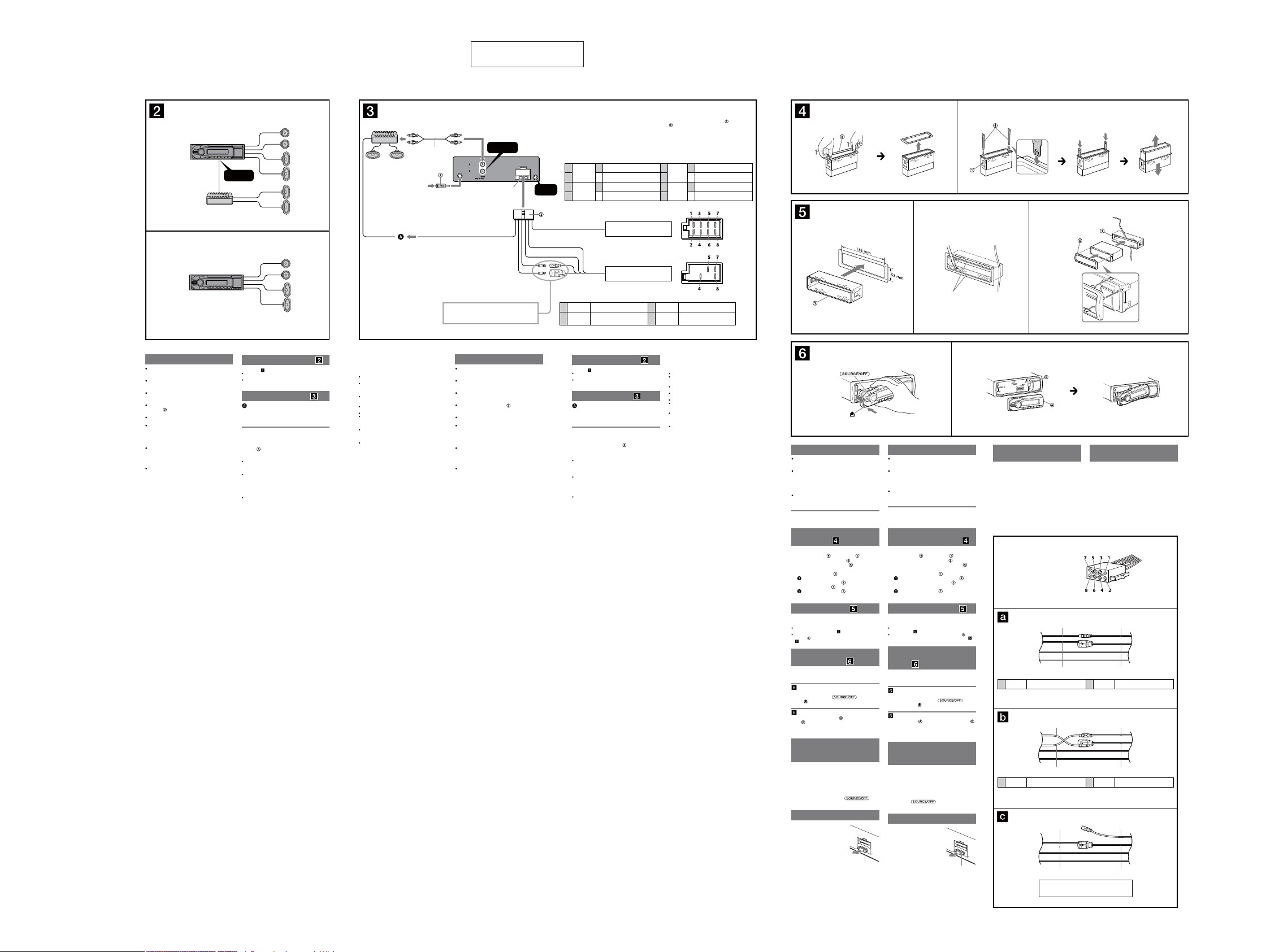
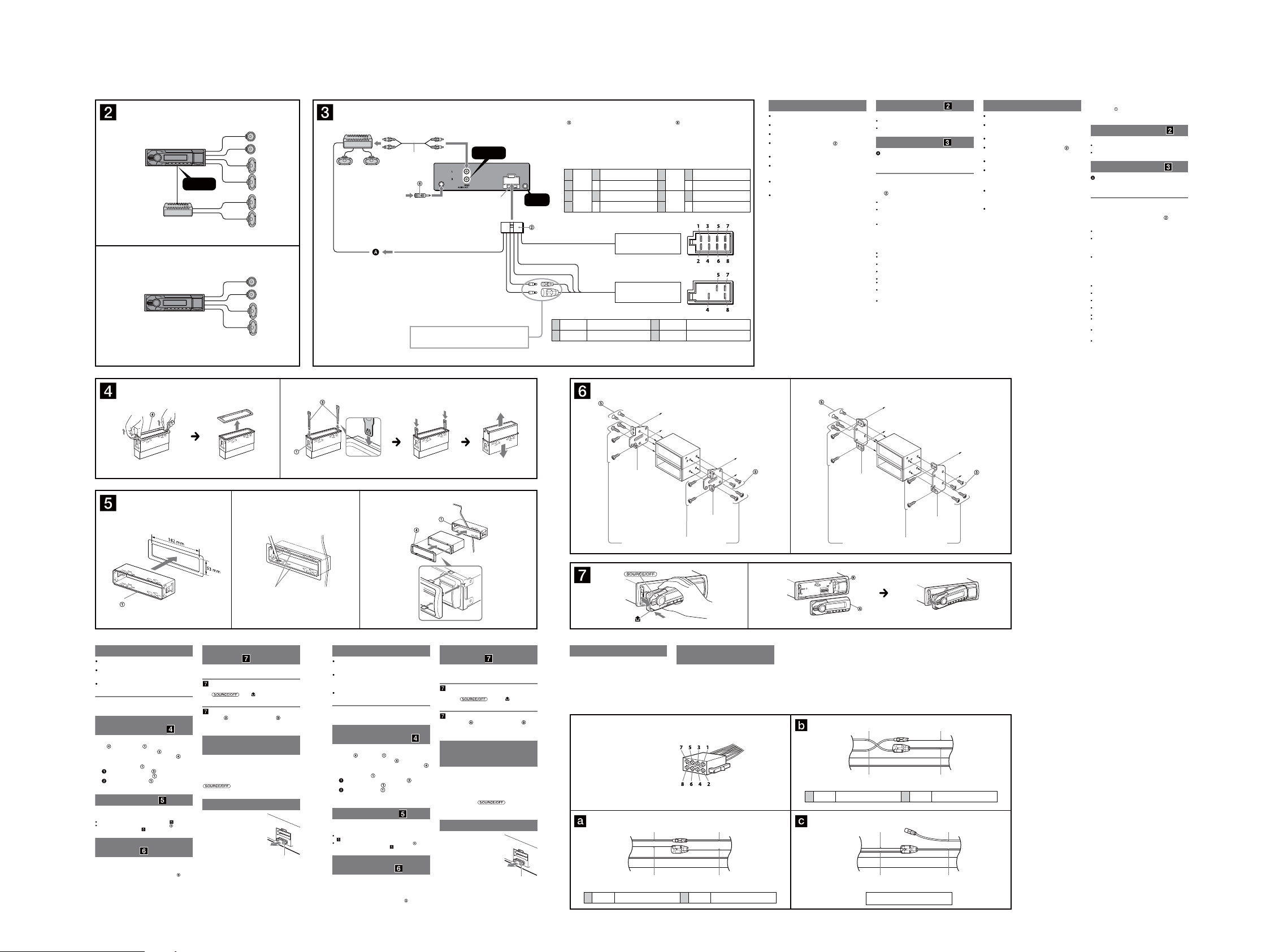
(AEP, Russian and UK models)
A
REAR
AUDIO OUT
B
1
от автомобильной антенны
*
від автомобільної радіоантени
2
*
С сине-белыми полосками
AMP REM
Макс. сила тока 0,3 А
Макс. сила струму – 0,3 A
У синьо-білу смужку
Подpобнee cм. в paздeлe “Cxeмa подключeния
питaния” нa обpaтной cтоpонe.
Для отримання детальної інформації див. «Схема
підключення живлення» на зворотній стороні.
This section is extracted
from instruction manual.
REAR
AUDIO OUT
1
2–
3
Предохранитель (10 А)
Запобіжник (10 A)
REMOTE
3
*
IN
4–
Позиции отрицательной полярности 2, 4, 6 и 8 имеют провода с полосками.
Проводка до позицій із від’ємною полярністю 2, 4, 6 і 8 – смугаста.
4
5
Позиции 1, 2, 3 и 6 не имеют контактных штырьков.
Позиції 1, 2, 3 та 6 не мають контактних штирків.
+
Фиолетовый
Фіолетовий
+
Серый
Сірий
Желтый
непрерывное поступление питания
Жовтий
неперервне постачання живлення
Синий
Синій
керування антеною з електроприводом
*1 Примечание о подсоединении антенны
Если антенна в Вашем автомобиле
относится к типу, утвержденному ISO
(Международной организацией по
стандартизации), используйте для ее
подсоединения прилагаемый переходник
Сначала подсоедините автомобильную
антенну к прилагаемому переходнику, а
затем к антенному гнезду аппарата.
2
*
Кабель с разъемами RCA (не входит в
комплект)
3
Может потребоваться отдельный
*
адаптер.
Громкоговоритель, задний, правый
Динамік: задній, правий
Громкоговоритель, задний, правый
Динамік: задній, правий
Громкоговоритель, передний, правый
Динамік: передній, правий
Громкоговоритель, передний, правый
Динамік: передній, правий
от разъема громкоговорителей
автомобиля
від роз’єму динаміка автомобіля
от разъема электропитания
автомобиля
від роз’єму живлення автомобіля
управление антенной с
электрическим приводом
7
8
1
*
Примітка до підключення радіоантени
Якщо автомобільна радіоантена належить
до типу ISO (Міжнародна організація зі
стандартизації), для її підключення
використовуйте адаптер
.
підключіть автомобільну антену до
адаптера з комплекту, а потім підключіть
її до гнізда антени в головному пристрої.
2
*
Шнур RCA з контактними штирками (не
надається в комплекті)
3
Може знадобитися окремий адаптер.
*
+
Белый
Білий
+
Зеленый
Зелений
импульсный источник питания
імпульсне постачання живлення
Громкоговоритель, передний, левый
Громкоговоритель, передний, левый
Громкоговоритель, задний, левый
Громкоговоритель, задний, левый
заземлення
5
6–
7
8–
Красный
Червоний
Черный
Чорний
. Спочатку
Динамік: передній, лівий
Динамік: передній, лівий
Динамік: задній, лівий
Динамік: задній, лівий
земля
21
Haпpaвьтe кpючок
внyтpь.
Гачком усередину.
1 23
Bыcтyпы
Фіксатори
Приборная пaнeль
Панель приладів
Внимание
Данный аппарат предназначен для подключения
только к аккумулятору 12 В постоянного тока с
отpицaтeльным заземлением.
He допycкaйтe попaдaния пpоводов под винты или
мeждy подвижными дeтaлями (нaпpимep, мeждy
нaпpaвляющими cидeний).
Пepeд выполнeниeм cоeдинeния выключитe
зaжигaниe aвтомобиля во избeжaниe коpоткого
зaмыкaния.
Сначала подсоедините соединительный кабель
к аппарату и громкоговорителям, а
питания
затем к контактам внешнего источника питания.
Подведите все провода заземления к одной
точке заземления.
B цeляx бeзопacноcти обязaтeльно изолиpyйтe вce
cвободныe нeподcоeдинeнныe пpоводa
изоляционной лeнтой.
Пpимeчaния отноcитeльно провода питания
(жeлтого)
Пpи подключeнии этого аппарата вмecтe c дpyгими
cтepeокомпонeнтaми номинaльноe знaчeниe cилы
токa в контype питaния aвтомобиля должно
пpeвышaть cyммapноe знaчeниe cилы токa,
yкaзaнноe нa пpeдоxpaнитeляx вcex компонeнтов.
Ecли номинaльноe знaчeниe cилы токa в контype
питaния aвтомобиля недостаточно выcокоe,
подcоeдинитe аппарат нaпpямyю к aккyмyлятоpy.
Пример подсоединения
Примечания ( -A)
Прежде чем подключать аппарат к усилителю, обязательно
подсоедините провод заземления.
Звуковой сигнал будет воспроизводиться только в том случае,
если используется встроенный усилитель.
Схема подсоединения
Подключeниe к вxодy AMP REMOTE IN
дополнитeльного ycилитeля мощноcти
Этот вapиaнт подключeния иcпользyeтcя только для
ycилитeлeй. Подключeниe любой дpyгой cиcтeмы можeт
пpивecти к повpeждeнию аппарата.
Предостережение
Если Вы используете антенну с электрическим
приводом без релейного блока, подсоединение этого
аппарата посредством прилагаемого провода
может привести к повреждению
питания
антенны.
О проводах управления и питания
При включении тюнера, а также использовании функции AF
(Альтернативные частоты) или TA (Сообщения о текущей
ситуации на дорогах) по проводу питания приемной антенны
(синий) подается +12 В постоянного тока.
Ecли нa зaднeм/боковом cтeклe aвтомобиля ycтaновлeнa
вcтpоeннaя aнтeннa диaпaзонa FM/MW/LW, подcоeдинитe
пpовод управления антенной с электрическим приводом
(cиний) или пpовод питaния аппарата (кpacный) к клeммe
питaния cyщecтвyющeго ycилитeля aнтeнны. Чтобы
полyчить дополнитeльныe cвeдeния, обpaтитecь к cвоeмy
дилepy.
Антенна с электрическим приводом, не снабженная релейным
блоком, с этим аппаратом использоваться не может.
Подсоединение для поддержки памяти
Когда к аппарату подсоединен желтый электрический провод,
блок памяти будет постоянно получать питание даже при
выключенном зажигании.
Примечания относительно подсоединения
громкоговорителей
Прежде чем подсоединять громкоговорители, выключите
аппарат.
Используйте громкоговорители с полным сопротивлением
4 - 8 Ом, обладающие способностью принимать достаточно
мощный сигнал. В противном случае они могут быть
повреждены.
Не подсоединяйте контактные гнезда громкоговорителей к
шасси автомобиля и не соединяйте гнезда правого
громкоговорителя с гнездами левого.
He подключaйтe пpовод зaзeмлeния аппарата к
отpицaтeльномy (–) контaктy гpомкоговоpитeля.
Не пытайтесь подсоединить громкоговорители параллельно.
Подсоединять можно только пассивные громкоговорители.
Подсоединение активных громкоговорителей (со встроенным
усилителем) к гнездам для громкоговорителей может
привести к повреждению аппарата.
Bо избeжaниe нeпpaвильной paботы аппарата нe иcпользyйтe
вcтpоeнныe в aвтомобиль пpоводa гpомкоговоpитeлeй, ecли
используется общий отpицaтeльный пpовод (–) для пpaвого и
лeвого гpомкоговоpитeлeй.
He подсоединяйте друг к другу пpоводa гpомокоговоpитeлeй
аппарата.
Пpимeчaниe отноcитeльно подcоeдинeния
Ecли гpомкоговоpитeль и ycилитeль подcоeдинeны нeпpaвильно,
нa диcплee отобpaзитcя нaдпиcь “ERROR-01”. B этом cлyчae
пpовepьтe пpaвильноcть подcоeдинeния гpомкоговоpитeля и
ycилитeля.
Увага!
Цей пристрій розроблено лише для роботи із
джерелом постійної напруги 12 В із заз емленням
від’ємного полюса.
Запобігайте попаданню проводки під гвинти або
між рухомих деталей (наприклад, поруччя
сидіння).
Перед створенням підключень вимкніть
запалювання автомобіля, щоб запобігти короткому
замиканню.
Підключіть кабель живлення до пристрою та
динаміків перед його підключенням до додаткового
роз’єму живлення.
Підключіть всі заземлені кабелі до однієї точки
заземлення.
Переконайтеся в тому, що будь-які вільні
непідключені кабелі ізольовано відповідною
ізолюючою стрічкою для забезпечення безпеки.
Примітки щодо кабелю підключення живлення
(жовтий)
За підключення пристрою разом з іншими
стереокомпонентами сила струму в контурі
автомобіля має бути вищою суми значень сили
струму, вказаної на плавких запобіжниках кожного
компонента.
Якщо сила струму в контурі автомобіля
недостатньо висока, підключіть пристрій
безпосередньо до акумулятора.
Приклад підключення
Примітка ( -A)
Перед підключенням підсилювача переконайтеся, що
підключено заземлений кабель.
Сигнал сповіщення спрацює, лише якщо використовується
вбудований підсилювач.
Схема підключення
Для AMP REMOTE IN додаткового підсилювача
потужності
Це підключення використовується лише для підсилювачів.
Підключення будь-якої іншої системи може пошкодити
пристрій.
Увага!
Якщо антена з електроприводом не має релейної
стійки, підключення цього пристрою за допомогою
кабелю живлення з комплекту
антену.
Примітка щодо кабелю керування та кабелю постачання
живлення
Кабель керування антеною з електроприводом (синій)
постачає +12 В постійної напруги за ввімкнення тюнера або під
час активації функції AF (Alternative Frequency) (альтернативна
частота) або TA (Trac Announcement) (повідомлення про
ситуацію на дорогах).
Якщо ваш автомобіль оснащено вбудованою антеною FM/MW/
LW на задньому/боковому склі, підключіть кабель керування
антеною (синій) або додатковий кабель підключення живлення
(червоний) до роз’єму живлення наявного антенного
підсилювача. Для отримання детальної інформації зверніться
до свого дилера з продажу.
Антену з електроприводом без релейної стійки не можна
використовувати з цим пристроєм.
може пошкодити
Підключення запам’ятовувальної системи
Якщо підключено жовтий кабель постачання живлення, живлення
завжди постачатиметься до запам’ятовувальної схеми навіть
за вимкненого запалення.
Примітка щодо підключення динаміка
Перед підключенням динаміків вимкніть пристрій.
Використовуйте динаміки з повним опором від 4 до 8 Ом і з
відповідною припустимою вхідною потужністю, щоб уникнути
їх пошкодження.
Не підключайте роз’єми динаміків до корпусу автомобіля і не
з’єднуйте роз’єми правого і лівого динаміка.
Не підключайте заземлений кабель цього пристрою до
від’ємного (–) роз’єму динаміка.
Не намагайтеся підключити динаміки паралельно.
Підключайте лише пасивні динаміки. Підключення активних
динаміків (із вбудованим підсилювачем) до роз’ємів динаміків
може пошкодити пристрій.
Щоб уникнути несправної роботи пристрою, не
використовуйте вбудований кабель динаміка, встановлений в
автомобілі, якщо пристрій використовує спільно негативний
(–) кабель для правого та лівого динаміків.
Не підключайте кабелі динаміка пристрою один до одного.
Примітка щодо підключення
Якщо динамік і підсилювач не підключено належним чином, на
дисплеї відобразиться «ERROR-01» (помилка). У такому випадку
переконайтеся, що динамік і підсилювач підключено належним
чином.
A
Меры предосторожности
Место для установки аппарата выбирайте
тщательно, чтобы он не мешал управлению
автомобилем.
Не устанавливайте аппарат там, где он будет
подвержен воздействию пыли, грязи, чрезмерной
вибрации или высоких температур, например в
местах, попадающих под прямые солнечные лучи
или находящихся вблизи вентиляционных решеток
обогревателей.
В целях обеспечения надежной и безопасной
установки используйте лишь входящие в комплект
монтажные детали.
Допустимый угол установки
Установите аппарат под углом не более 45°.
Cнятиe зaщитной мaнжeты и
кpонштeйнa
Пepeд ycтaновкой аппарата снимите с него
зaщитнyю мaнжeтy
1
2
Пpимep ycтaновки
Установка аппарата в приборной пaнeли
Пpимeчaния
Пpи нeобxодимоcти отогнитe эти выcтyпы нapyжy, чтобы
обecпeчить плотнyю подгонкy (
Убeдитecь, что 4 фикcaтоpa, имeющиecя нa зaщитной
мaнжeтe
(
Порядок снятия и установки
передней панели
Перед установкой аппарата снимите с него
переднюю панель.
Прежде чем снимать переднюю панель, обязательно
нажмите и удерживайте
кнопку
Сначала присоедините часть передней панели к
части
а затем вдвиньте в паз левую часть панели до легкого
щелчка.
Внимание. Если в замке
зажигания нет положения
ACC
Задайте функцию автоматического выключения. Для
получения дополнительной информации см.
прилагаемые инструкции по эксплуатации.
После выключения аппарата его питание будет
автоматически отключено в установленное время,
что предотвращает разрядку аккумулятора.
Если функция автоматического выключения не
задана, то при каждом выключении зажигания
нажмите и удерживайте кнопку
тех пор, пока дисплей не погаснет.
Замена предохранителя
При замене предохранителей
обязательно используйте только
те, которые соответствуют силе
тока, указанной на оригинальном
предохранителе. Если перегорел
предохранитель, проверьте
подключение питания и замените
предохранитель. Если после
замены предохранитель снова
перегорел, это может означать
неисправность устройства. В этом
случае обратитесь к ближайшему
дилеру Sony.
и кpонштeйн .
Cнятиe зaщитной мaнжeты .
Снимите защитную манжету , зацепив ее за
края.
Cнятиe кpонштeйнa .
Bcтaвьтe одновpeмeнно до щeлчкa обa
ключa для дeмонтaжa
и кpонштeйном
Потянитe кpонштeйн вниз, a аппарат
- ввepx, чтобы отдeлить одно от дpyгого.
, нaдeжно вcтaвлeны в отвepcтия нa аппарате
-3).
мeждy аппаратом
.
-2).
-A Снятие панели
, затем снимите панель, потянув ее на себя.
. Нажмите
-B Установка панели
аппарата, как это показано на иллюстрации,
Предохранитель
(10 А)
до
B
Заходи безпеки
Уважно виберіть місце для встановлення, щоб
пристрій не перешкоджав нормальному керуванню
автомобілем.
Уникайте встановлення пристрою у місцях, що
піддаються впливу пилу, бруду, надмірної вібрації
або високої температури, наприклад, у місцях, на
які падає пряме сонячне проміння, або біля
вентиляційних отворів обігрівача.
Для безпечного та надійного встановлення
використовуйте монтажне обладнання тільки з
комплекту поставки.
Регулювання кута встановлення
Відрегулюйте кут встановлення таким чином, щоб
він був не більше 45°.
Від’єднання захисної
манжети та кронштейна
Перед встановленням апарата від’єднайте
захисну манжету
1
2
Встановлення в панелі приладів
Примітки
Перед встановленням апарата від’єднайте
передню панель.
Перш ніж від’єднати передню панель, обов’язково
натисніть і утримуйте кнопку
Натисніть кнопку
З’єднайте частину передньої панелі з частиною
пристрою, як показано на ілюстрації, і натискайте на
ліву сторону, доки панель, клацнувши, не стане на
місце.
Обов’язково налаштуйте функцію автоматичного
вимкнення. Для отримання детальної інформації
див. інструкції з експлуатації, які постачаються в
комплекті. Після вимкнення пристрою він
автоматично вимкне живлення у встановлений час,
що запобігає витраті заряду акумулятора. Якщо
функцію автоматичного вимкнення не встановлено,
після кожного вимикання запалювання натискайте
та утримуйте
зображення на дисплеї.
Замінюючи запобіжник,
переконайтеся, що новий
запобіжник розрахований на таку
саму силу струму, як і
оригінальний. Якщо запобіжник
перегорає, перевірте підключення
живлення та замініть запобіжник.
Якщо запобіжник перегорає
знову після заміни, причиною
цього може бути внутрішня
неполадка. У такому разі
зверніться до найближчого
дилера Sony.
та кронштейн від апарата.
Від’єднання захисної манжети .
Захопіть обидва краї захисної манжети , а
потім витягніть її.
Від’єднання кронштейна .
Вставте обидва демонтажні ключі разом
між апаратом і кронштейном
пролунає клацання.
Потягніть кронштейн донизу, а потім
потягніть виріб догори, щоб роз’єднати їх.
, доки не
Приклад встановлення
Якщо потрібно, вигніть ці виступи назовні, щоб забезпечити
щільну фіксацію (
-2).
Переконайтеся, що 4 фіксатори на захисній манжеті
належним чином встановлені в отвори, наявні в апараті (
Порядок від’єднання і
приєднання передньої
панелі
-A Для від’єднання
і потягніть панель до себе.
.
-B Для приєднання
Увага. Якщо у замку
запалювання автомобіля
немає положення ACC
, доки не зникне
Заміна запобіжника
Запобіжник (10 A)
Схема подключения
питания
В разных автомобилях могут использоваться разные
дополнительные разъемы питания. Чтобы убедиться
в правильности подсоединения, обpaтитecь к cxeмe
подключения дополнительного разъема питания
Вашего автомобиля. Есть три основных типа (как
показано на рисунке ниже). Возможно, Вам придется
поменять местами подключение красного и желтого
проводов в соединительном кабеле питания
стереосистемы.
После проверки пpaвильноcти подключeния в
paзъeмax подключите аппарат к электропитанию
автомобиля. Если у Вас есть какие-либо вопросы или
проблемы, связанные с подключением аппарата,
которые не рассматриваются в настоящем
руководстве, обратитесь за советом к дилеру
автомобильной фирмы.
Дополнительный разъем питания
Додатковий роз’єм живлення
-3).
Желтый
4
неперервне постачання живлення
Жовтий
импульсный источник питания
Желтый
4
Жовтий
Красный
Червоний
Желтый
Жовтий
непрерывное поступление питания
Красный
Червоний
Желтый
Жовтий
імпульсне постачання живлення
Красный
Червоний
Желтый
Жовтий
автомобиль не имеет положения АСС
автомобіль не має положення ACC
Схема підключення
живлення
Допоміжний роз’єм живлення може бути різним
залежно від автомобіля. Перевірте схему
допоміжного роз’єму живлення у своєму автомобілі,
щоб впевнитися у правильності з’єднань. Існує три
основні типи (показано нижче). Може знадобитися
поміняти місцями положення червоного і жовтого
дротів у кабелі живлення автомобільної
стереосистеми.
Перевіривши правильність підключення в роз’ємах,
підключіть пристрій до електроживлення автомобіля.
Якщо виникли запитання або проблеми з пристроєм,
не описані в цій інструкції, зверніться за допомогою
до дилера автомобільної компанії.
Красный
Червоний
Желтый
Жовтий
импульсный источник питания
Красный
7
Червоний
імпульсне постачання живлення
Красный
Червоний
Желтый
Жовтий
непрерывное поступление питания
Красный
7
Червоний
неперервне постачання живлення
Красный
Червоний
Желтый
Жовтий
DSX-A30/A30E
44
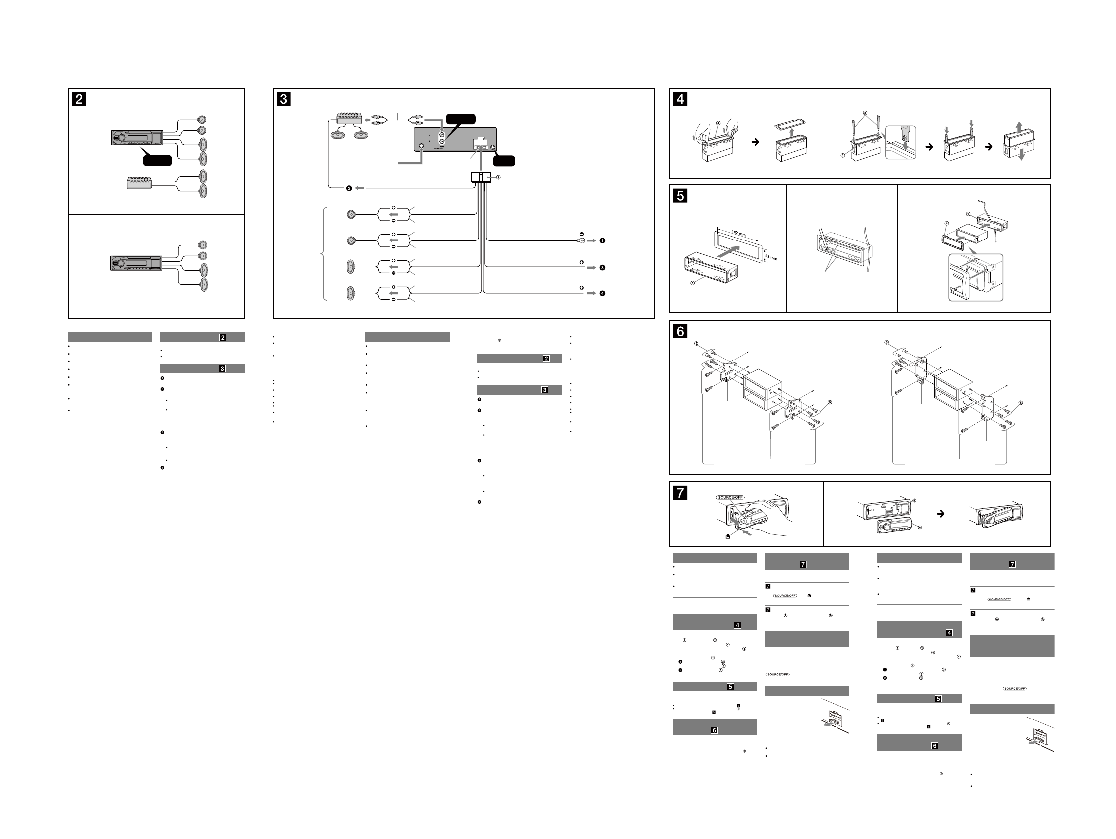
(E, Saudi Arabia, Mexican and Indian models)
A
REAR
AUDIO OUT
B
DSX-A30/A30E
1
*1 Speaker impedance: 4 – 8 ohms × 4
2
*
RCA pin cord (not supplied).
3
*
Black
Negro
Red
Rojo
Yellow
Amarillo
REMOTE
*
IN
3
Separate adaptor may be required.
2
*
from car antenna (aerial)
desde la antena del automóvil
Blue/white striped
REM OUT
Max. supply current 0.4 A
Corriente máx. de alimentación de 0,4 A
Left
Izquierdo
Right
Derecho
1
*
Left
Izquierdo
Right
Derecho
Con rayas azules y blancas
White
Blanco
White/black striped
Con rayas blancas y negras
Gray
Gris
Gray/black striped
Con rayas grises y negras
Green
Verde
Green/black striped
Con rayas verdes y negras
Purple
Morado
Purple/black striped
Con rayas moradas y negras
REAR
AUDIO OUT
Fuse (10 A)
Fusible (10 A)
Impedancia de los altavoces: de 4 a 8 Ω × 4
*
2
*
Cable con terminales RCA (no suministrado).
3
*
Puede requerirse un adaptador independiente.
ACC
BATTERY
Claws
Uñas
2
Face the hook inwards.
El gancho debe
encontrarse en la parte
interior.
Dashboard
Tablero
1
1 23
Cautions
is unit is designed for negative ground (earth) 12 V
DC operation only.
Do not get the leads under a screw, or caught in moving
parts (e.g. seat railing).
Before making connections, turn the car ignition off to
avoid short circuits.
Connect the yellow and red power input leads only
after all other leads have been connected.
Run all ground (earth) leads to a common ground
(earth) point.
Be sure to insulate any loose unconnected leads with
electrical tape for safety.
Notes on the power supply lead (yellow)
When connecting this unit in combination with other
stereo components, the connected car circuit’s rating
must be higher than the sum of each component’s fuse.
When no car circuits are rated high enough, connect
the unit directly to the battery.
DSX-A30/A30E
Connection example
Notes
Be sure to connect the ground (earth) lead before connecting the
amplier.
The alarm will only sound if the built-in amplier is used.
Connection diagram
To a metal surface of the car
First connect the black ground (earth) lead, then connect the
yellow, and red power supply leads.
To the power antenna (aerial) control lead or
power supply lead of antenna (aerial) booster
Notes
It is not necessary to connect this lead if there is no power
antenna (aerial) or antenna (aerial) booster, or with a
manually-operated telescopic antenna (aerial).
When your car has a built-in FM/AM antenna (aerial) in the rear/
side glass, see “Notes on the control and power supply leads.”
To AMP REMOTE IN of an optional power
amplier
This connection is only for ampliers. Connecting any other system
may damage the unit.
To the +12 V power terminal which is energized
in the accessory position of the ignition key
switch
Notes
If there is no accessory position, connect to the +12 V power
(battery) terminal which is energized at all times.
Be sure to connect the black ground (earth) lead to a metal
surface of the car rst.
When your car has a built-in FM/AM antenna (aerial) in the rear/
side glass, see “Notes on the control and power supply leads.”
To the +12 V power terminal which is energized
at all times
Be sure to connect the black ground (earth) lead to a metal surface
of the car rst.
Notes on the control and power supply leads
REM OUT lead (blue/white striped) supplies +12 V DC when you turn
on the unit.
When your car has built-in FM/AM antenna (aerial) in the rear/side
glass, connect REM OUT lead (blue/white striped) or the accessory
power supply lead (red) to the power terminal of the existing antenna
(aerial) booster. For details, consult your dealer.
A power antenna (aerial) without a relay box cannot be used with this
unit.
Memory hold connection
When the yellow power input lead is connected, power will always be
supplied to the memory circuit even when the ignition switch is turned
o.
Notes on speaker connection
Before connecting the speakers, turn the unit o.
Use speakers with an impedance of 4 to 8 ohms, and with adequate
power handling capacities to avoid its damage.
Do not connect the speaker terminals to the car chassis, or connect the
terminals of the right speakers with those of the left speaker.
Do not connect the ground (earth) lead of this unit to the negative (–)
terminal of the speaker.
Do not attempt to connect the speakers in parallel.
Connect only passive speakers. Connecting active speakers (with
built-in ampliers) to the speaker terminals may damage the unit.
To avoid a malfunction, do not use the built-in speaker leads installed
in your car if the unit shares a common negative (–) lead for the right
and left speakers.
Do not connect the unit’s speaker leads to each other.
Note on connection
If speaker and amplier are not connected correctly, “ERROR-01” appears
in the display. In this case, make sure the speaker and amplier are
connected correctly.
Precauciones
Esta unidad ha sido diseñada para alimentarse sólo con
cc de 12 V de masa negativa.
No coloque los cables debajo de ningún tornillo, ni los
aprisione con partes móviles (p. ej. los rieles del
asiento).
Antes de realizar las conexiones, apague el automóvil
para evitar cortocircuitos.
Conecte los cables de fuente de alimentación amarillo
y rojo solamente después de haber conectado los
demás.
Conecte todos los cables de conexión a masa a un
punto común.
Por razones de seguridad, asegúrese de aislar con cinta
aislante los cables sueltos que no estén conectados.
Notas sobre el cable de fuente de alimentación
(amarillo)
Cuando conecte esta unidad en combinación con otros
componentes estéreo, la capacidad nominal del circuito
conectado del automóvil debe ser superior a la suma del
fusible de cada componente.
Si no hay circuitos del automóvil con capacidad
nominal suficientemente alta, conecte la unidad
directamente a la batería.
Nota
Antes de instalar la unidad, compruebe que los enganches de ambos
lados del soporte
estén doblados hacia adentro 2 mm. Si no lo están
o están doblados hacia afuera, la unidad no se instalará correctamente
y puede saltar.
Ejemplo de conexiones
Notas
Asegúrese de conectar primero el cable de conexión a masa antes de
realizar la conexión del amplicador.
La alarma sonará únicamente si se utiliza el amplicador incorporado.
Diagrama de conexión
A una supercie metálica del automóvil
Conecte primero el cable de conexión a masa negro, y después los
cables amarillo y rojo de fuente de alimentación.
Al cable de control de la antena motorizada o al
cable de fuente de alimentación del
amplicador de señal de la antena
Notas
Si no se dispone de antena motorizada ni de amplicador de
señal de la antena, o se utiliza una antena telescópica accionada
manualmente, no será necesario conectar este cable.
Si el automóvil tiene una antena de FM/AM incorporada en el
cristal trasero o lateral, consulte “Notas sobre los cables de
control y de fuente de alimentación”.
A AMP REMOTE IN de un amplicador de
potencia opcional
Esta conexión es sólo para amplicadores. La conexión de cualquier
otro sistema puede dañar la unidad.
Al terminal de alimentación de +12 V que recibe
energía en la posición de accesorio del
interruptor de encendido
Notas
Si no hay posición de accesorio, conéctelo al terminal de
alimentación (batería) de +12 V que recibe energía sin
interrupción.
Asegúrese de conectar primero el cable de conexión a masa
negro a una supercie metálica del automóvil.
Si el automóvil tiene una antena de FM/AM incorporada en el
cristal trasero o lateral, consulte “Notas sobre los cables de
control y de fuente de alimentación”.
Al terminal de alimentación de +12 V que recibe
energía sin interrupción
Asegúrese de conectar primero el cable de conexión a masa negro a
una supercie metálica del automóvil.
Notas sobre los cables de control y de fuente de alimentación
El cable REM OUT (rayado azul y blanco) suministra cc +12 V al
encender la unidad.
Si el automóvil dispone de una antena de FM/AM incorporada en el
cristal trasero o lateral, conecte el cable REM OUT (rayado azul y
blanco) o el cable de fuente de alimentación auxiliar (rojo) al terminal
de alimentación del amplicador de señal de la antena existente. Para
obtener más detalles, consulte a su distribuidor.
Con esta unidad no es posible utilizar una antena motorizada sin caja
de relé.
Conexión para protección de la memoria
Si conecta el cable de fuente de alimentación amarillo, el circuito de la
memoria recibirá siempre alimentación, aunque apague el interruptor
de encendido.
Notas sobre la conexión de los altavoces
Antes de conectar los altavoces, desconecte la alimentación de la
unidad.
Utilice altavoces con una impedancia de 4 a 8 Ω con la capacidad de
potencia adecuada para evitar que se dañen.
No conecte los terminales de altavoz al chasis del automóvil, ni
conecte los terminales del altavoz derecho con los del izquierdo.
No conecte el cable de conexión a masa de esta unidad al terminal
negativo (–) del altavoz.
No intente conectar los altavoces en paralelo.
Conecte solamente altavoces pasivos. Si conecta altavoces activos
(con amplicadores incorporados) a los terminales de altavoz, puede
dañar la unidad.
Para evitar fallas de funcionamiento, no utilice los cables de altavoz
incorporados instalados en el automóvil si la unidad comparte un
cable negativo común (–) para los altavoces derecho e izquierdo.
No conecte los cables de altavoz de la unidad entre sí.
Nota sobre la conexión
Si el altavoz y el amplicador no están conectados correctamente,
aparecerá “ERROR-01” en la pantalla. Si es así, compruebe la conexión
de ambos dispositivos.
55
A TOYOTA B NISSAN
size
5 × max. 8 mm
7
/32 × max. 5/16 in)
(
Tamaño
5 × 8 mm máx.
Bracket
Soporte
Existing parts supplied with your car
Piezas existentes suministradas con su automóvil
to dashboard/center console
al tablero o consola central
Bracket
Soporte
size
5 × max. 8 mm
7
/32 × max. 5/16 in)
(
Tamaño
5 × 8 mm máx.
size
5 × max. 8 mm
7
/32 × max. 5/16 in)
(
Tamaño
5 × 8 mm máx.
Bracket
Soporte
Existing parts supplied with your car
Piezas existentes suministradas con su automóvil
AB
Precautions
Choose the installation location carefully so that the
unit will not interfere with normal driving operations.
Avoid installing the unit in areas subject to dust, dirt,
excessive vibration, or high temperatures, such as in
direct sunlight or near heater ducts.
Use only the supplied mounting hardware for a safe and
secure installation.
Mounting angle adjustment
Adjust the mounting angle to less than 45°.
Removing the protection
collar and the bracket
Before installing the unit, remove the protection
and the bracket from the unit.
collar
Remove the protection collar .
1
Pinch both edges of the protection collar , then
pull it out.
Remove the bracket .
2
Insert both release keys together between
the unit and the bracket
Pull down the bracket , then pull up the unit
to separate.
until they click.
Mounting example
Installation in the dashboard
Notes
Bend these claws outward for a tight t, if necessary ( -2).
Make sure that the 4 catches on the protection collar are properly
engaged in the slots of the unit (
Mounting the unit in a
Japanese car
You may not be able to install this unit in some makes of
Japanese cars. In such a case, consult your Sony dealer.
Note
To prevent malfunction, install only with the supplied screws
-3).
.
How to detach and attach the
front panel
Before installing the unit, detach the front panel.
-A To detach
Before detaching the front panel, be sure to press and
hold
you.
Engage part of the front panel with part of the unit,
as illustrated, and push the le side into position until it
clicks.
Be sure to set the Auto Off function. For details, see the
supplied Operating Instructions.
e unit will shut off completely and automatically in the
set time aer the unit is turned off, which prevents
battery drain.
If you do not set the Auto Off function, press and hold
you turn the ignition off.
. Press and pull it off towards
-B To attach
Warning if your car’s ignition
has no ACC position
until the display disappears each time
Fuse replacement
When replacing the fuse, be sure to
use one matching the amperage
rating stated on the original fuse. If
the fuse blows, check the power
connection and replace the fuse. If
the fuse blows again after
replacement, there may be an
internal malfunction. In such a case,
consult your nearest Sony dealer.
Notes on the tuning step
For how to set the tuning step, see the supplied
Operating Instructions.
If replacing the car battery or changing the connections,
the tuning step setting will be erased.
Fuse (10 A)
Precauciones
Elija cuidadosamente el lugar de montaje de forma que
la unidad no interera con las funciones normales de
conducción.
Evite instalar la unidad donde pueda quedar expuesta a
polvo, suciedad, vibraciones excesivas o altas
temperaturas, por ejemplo, a la luz solar directa o cerca
de conductos de calefacción.
Para realizar una instalación segura y rme, utilice
solamente elementos de instalación suministrados.
Ajuste del ángulo de montaje
Ajuste el ángulo de montaje a menos de 45°.
Extracción del marco de
protección y del soporte
Antes de instalar la unidad, retire el marco de
y el soporte de la misma.
protección
Retire el marco de protección .
1
Apriete ambos bordes del marco de protección
y, a continuación, tire de él hacia fuera.
Retire el soporte .
2
Inserte ambas llaves de liberación entre la
unidad y el soporte
Presione el soporte y, a continuación,
levante la unidad para separar ambos
elementos.
Ejemplo de montaje
Instalación en el tablero
Notas
Si es necesario, doble las uñas hacia fuera para que encaje rmemente
-2).
(
Compruebe que los 4 enganches del marco de protección estén
bien jados en las ranuras de la unidad (
Montaje de la unidad en un
automóvil japonés
Es posible que no pueda instalar esta unidad en algunos
automóviles japoneses. En tal caso, consulte a su
distribuidor Sony.
Nota
Para evitar que se produzcan fallas de funcionamiento, realice la
instalación solamente con los tornillos suministrados
hasta que encajen.
-3).
.
to dashboard/center console
al tablero o consola central
size
5 × max. 8 mm
7
/32 × max. 5/16 in)
(
Tamaño
5 × 8 mm máx.
Bracket
Soporte
Forma de extraer e instalar el
panel frontal
Antes de instalar la unidad, extraiga el panel
frontal.
-A Para extraerlo
Antes de extraer el panel frontal, asegúrese de mantener
presionado
extráigalo hacia usted.
-B Para instalarlo
Coloque la parte del panel frontal en la parte de la
unidad, como se muestra en la ilustración, y después
presione la parte izquierda hasta que encaje.
Advertencia: si el encendido
del automóvil no dispone de
una posición ACC
Asegúrese de ajustar la función de desconexión
automática. Para obtener más información, consulte el
manual de instrucciones suministrado.
La unidad se apagará completa y automáticamente en el
tiempo establecido después de que se desconecte la
unidad, lo que evita que se desgaste la batería.
Si no ha ajustado la función de desconexión automática,
mantenga presionado
apague el interruptor de encendido, hasta que la pantalla
desaparezca.
. Presione y luego
cada vez que
Sustitución del fusible
Al sustituir el fusible, asegúrese de
utilizar uno cuyo amperaje coincida
con el especicado en el original. Si
el fusible se funde, verique la
conexión de alimentación y
sustitúyalo. Si el fusible vuelve a
fundirse después de sustituirlo, es
posible que exista alguna falla de
funcionamiento interno. En tal caso,
consulte con el distribuidor Sony
más cercano.
Notas acerca de la sintonización
Para obtener información sobre cómo ajustar la
sintonización, consulte el manual de instrucciones
suministrado.
Si se reemplaza la batería del auto o se cambian las
conecciones, la configuración de la sintonización se va
a borrar.
Fusible (10 A)
DSX-A30/A30E
Ver. 1.2
(Argentina model)
A
B
REAR
AUDIO OUT
Nota
*1 Note for the antenna (aerial) connecting
If your car antenna (aerial) is an ISO (International
Organization for Standardization) type, use the supplied
adaptor
to connect it. First connect the car antenna
(aerial) to the supplied adaptor, then connect it to the
antenna (aerial) jack of the master unit.
2
*
RCA pin cord (not supplied).
3
*
Separate adaptor may be required.
2
*
*1 from car antenna (aerial)
desde la antena del automóvil
Max. supply current 0.3 A
Corriente máx. de alimentación
de 0,3 A
AMP REM
Blue/white striped
Con rayas azules y blancas
See “Power connection diagram” on the reverse side for details.
Para obtener más información, consulte el “Diagrama de
conexión de la alimentación” que encontrará al dorso.
REAR
AUDIO OUT
Fuse (10 A)
Fusible (10 A)
REMOTE
*
IN
3
1
Purple
Morado
2–
3
4–
Negative polarity positions 2, 4, 6, and 8 have striped leads.
Los cables de las posiciones de polaridad negativa 2, 4, 6 y 8 son rayados.
Yellow
4
Amarillo
Blue
5
Azul
Positions 1, 2, 3 and 6 do not have pins.
Las posiciones 1, 2, 3 y 6 no tienen pines.
Speaker, Rear, Right
+
Altavoz, posterior, derecho
Speaker, Rear, Right
Altavoz, posterior, derecho
Speaker, Front, Right
+
Altavoz, frontal, derecho
Gray
Gris
Speaker, Front, Right
Altavoz, frontal, derecho
continuous power supply
fuente de alimentación continua
power antenna (aerial) control
control de la antena motorizada
1
Nota sobre la conexión de la antena
*
Si la antena del automóvil es del tipo ISO (International
Organization for Standardization), emplee el adaptador
suministrado
la antena del automóvil al adaptador suministrado y, a
continuación, a la toma de antena de la unidad principal.
2
*
Cable con terminales RCA (no suministrado)
3
*
Puede requerirse un adaptador independiente.
5
6–
7
8–
from the car’s speaker connector
desde un conector de altavoces
del automóvil
from the car’s power connector
desde un conector de
alimentación del automóvil
7
8
para conectarla. En primer lugar, conecte
Speaker, Front, Left
+
Altavoz, frontal, izquierdo
White
Blanco
Red
Rojo
Black
Negro
Green
Verde
Speaker, Front, Left
Altavoz, frontal, izquierdo
Speaker, Rear, Left
+
Altavoz, posterior, izquierdo
Speaker, Rear, Left
Altavoz, posterior, izquierdo
switched power supply
fuente de alimentación conmutada
earth
masa
Cautions
is unit is designed for negative ground (earth) 12 V
DC operation only.
Do not get the leads under a screw, or caught in moving
parts (e.g. seat railing).
Before making connections, turn the car ignition off to
avoid short circuits.
Connect the power connecting lead to the unit and
speakers before connecting it to the auxiliary power
connector.
Run all ground (earth) leads to a common ground
(earth) point.
Be sure to insulate any loose unconnected leads with
electrical tape for safety.
Notes on the power supply lead (yellow)
When connecting this unit in combination with other
stereo components, the connected car circuit’s rating
must be higher than the sum of each component’s fuse.
When no car circuits are rated high enough, connect
the unit directly to the battery.
Connection example
Notes
Be sure to connect the ground (earth) lead before connecting the
amplier.
The alarm will only sound if the built-in amplier is used.
Connection diagram
To AMP REMOTE IN of an optional power
amplier
This connection is only for ampliers. Connecting any other system
may damage the unit.
Warning
If you have a power antenna (aerial) without a relay box,
connecting this unit with the supplied power connecting
may damage the antenna (aerial).
lead
Notes on the control and power supply leads
The power antenna (aerial) control lead (blue) supplies +12 V DC when
you turn on the tuner.
When your car has built-in FM/AM antenna (aerial) in the rear/side
glass, connect the power antenna (aerial) control lead (blue) or the
accessory power supply lead (red) to the power terminal of the existing
antenna (aerial) booster. For details, consult your dealer.
A power antenna (aerial) without a relay box cannot be used with this
unit.
Memory hold connection
When the yellow power input lead is connected, power will always be
supplied to the memory circuit even when the ignition switch is turned
o.
Notes on speaker connection
Before connecting the speakers, turn the unit o.
Use speakers with an impedance of 4 to 8 ohms, and with adequate
power handling capacities to avoid its damage.
Do not connect the speaker terminals to the car chassis, or connect the
terminals of the right speakers with those of the left speaker.
Do not connect the ground (earth) lead of this unit to the negative (–)
terminal of the speaker.
Do not attempt to connect the speakers in parallel.
Connect only passive speakers. Connecting active speakers (with
built-in ampliers) to the speaker terminals may damage the unit.
To avoid a malfunction, do not use the built-in speaker leads installed
in your car if the unit shares a common negative (–) lead for the right
and left speakers.
Do not connect the unit’s speaker leads to each other.
Note on connection
If speaker and amplier are not connected correctly, “ERROR-01” appears
in the display. In this case, make sure the speaker and amplier are
connected correctly.
Precauciones
Esta unidad ha sido diseñada para alimentarse sólo con
cc de 12 V de masa negativa.
No coloque los cables debajo de ningún tornillo, ni los
aprisione con partes móviles (p. ej. los rieles del
asiento).
Antes de realizar las conexiones, apague el automóvil
para evitar cortocircuitos.
Conecte el cable de conexión de alimentación a la
unidad y a los altavoces antes de conectarlo al conector
de alimentación auxiliar.
Conecte todos los cables de conexión a masa a un
punto común.
Por razones de seguridad, asegúrese de aislar con cinta
aislante los cables sueltos que no estén conectados.
Notas sobre el cable de fuente de alimentación
(amarillo)
Cuando conecte esta unidad en combinación con otros
componentes estéreo, la capacidad nominal del circuito
conectado del automóvil debe ser superior a la suma del
fusible de cada componente.
Si no hay circuitos del automóvil con capacidad
nominal suficientemente alta, conecte la unidad
directamente a la batería.
Antes de instalar la unidad, compruebe que los enganches de ambos
lados del soporte
estén doblados hacia adentro 2 mm. Si no lo están
o están doblados hacia afuera, la unidad no se instalará correctamente
y puede saltar.
Ejemplo de conexiones
Notas
Asegúrese de conectar primero el cable de conexión a masa antes de
realizar la conexión del amplicador.
La alarma sonará únicamente si se utiliza el amplicador incorporado.
Diagrama de conexión
A AMP REMOTE IN de un amplicador de
potencia opcional
Esta conexión es sólo para amplicadores. La conexión de cualquier
otro sistema puede dañar la unidad.
Advertencia
Si la antena motorizada no dispone de caja de relé, es
posible que la conexión de esta unidad mediante el cable
de conexión de alimentación suministrado
daños en la antena.
Notas sobre los cables de control y de fuente de alimentación
El cable de control de la antena motorizada (azul) suministrará cc de +
12 V cuando conecte la alimentación del sintonizador.
Si el automóvil dispone de una antena de FM/AM incorporada en el
cristal trasero o lateral, conecte el cable de control de antena
motorizada (azul) o el cable de fuente de alimentación auxiliar (rojo)
al terminal de alimentación del amplicador de señal de la antena
existente. Para obtener más información, consulte a su distribuidor.
Con esta unidad no es posible utilizar una antena motorizada sin caja
de relé.
Conexión para protección de la memoria
Si conecta el cable de fuente de alimentación amarillo, el circuito de la
memoria recibirá siempre alimentación, aunque apague el interruptor
de encendido.
Notas sobre la conexión de los altavoces
Antes de conectar los altavoces, desconecte la alimentación de la
unidad.
Utilice altavoces con una impedancia de 4 a 8 Ω con la capacidad de
potencia adecuada para evitar que se dañen.
No conecte los terminales de altavoz al chasis del automóvil, ni
conecte los terminales del altavoz derecho con los del izquierdo.
No conecte el cable de conexión a masa de esta unidad al terminal
negativo (–) del altavoz.
No intente conectar los altavoces en paralelo.
Conecte solamente altavoces pasivos. Si conecta altavoces activos
(con amplicadores incorporados) a los terminales de altavoz, puede
dañar la unidad.
Para evitar fallas de funcionamiento, no utilice los cables de altavoz
incorporados instalados en el automóvil si la unidad comparte un
cable negativo común (–) para los altavoces derecho e izquierdo.
No conecte los cables de altavoz de la unidad entre sí.
Nota sobre la conexión
Si el altavoz y el amplicador no están conectados correctamente,
aparecerá “ERROR-01” en la pantalla. Si es así, compruebe la conexión
de ambos dispositivos.
provoque
Precautions
Choose the installation location carefully so that the
unit will not interfere with normal driving operations.
Avoid installing the unit in areas subject to dust, dirt,
excessive vibration, or high temperatures, such as in
direct sunlight or near heater ducts.
Use only the supplied mounting hardware for a safe and
secure installation.
Mounting angle adjustment
Adjust the mounting angle to less than 45°.
Removing the protection
collar and the bracket
Before installing the unit, remove the protection
collar
1
2
Mounting example
Installation in the dashboard
Notes
Bend these claws outward for a tight t, if necessary ( -2).
Make sure that the 4 catches on the protection collar are properly
engaged in the slots of the unit (
Mounting the unit in a
Japanese car
You may not be able to install this unit in some makes of
Japanese cars. In such a case, consult your Sony dealer.
Note
To prevent malfunction, install only with the supplied screws
DSX-A30/A30E
1
1
and the bracket from the unit.
Remove the protection collar .
Pinch both edges of the protection collar , then
pull it out.
Remove the bracket .
Insert both release keys together between
the unit and the bracket
Pull down the bracket , then pull up the unit
to separate.
until they click.
-3).
.
2
Face the hook inwards.
El gancho debe
encontrarse en la parte
interior.
23
Claws
Uñas
How to detach and attach the
front panel
Before installing the unit, detach the front panel.
-A To detach
Before detaching the front panel, be sure to press and
hold
you.
Engage part of the front panel with part of the unit,
as illustrated, and push the le side into position until it
clicks.
Warning if your car’s ignition
has no ACC position
Be sure to set the Auto Off function. For details, see the
supplied Operating Instructions.
e unit will shut off completely and automatically in the
set time aer the unit is turned off, which prevents
battery drain.
If you do not set the Auto Off function, press and hold
you turn the ignition off.
. Press and pull it off towards
-B To attach
until the display disappears each time
Fuse replacement
When replacing the fuse, be sure to
use one matching the amperage
rating stated on the original fuse. If
the fuse blows, check the power
connection and replace the fuse. If
the fuse blows again after
replacement, there may be an
internal malfunction. In such a case,
consult your nearest Sony dealer.
Fuse (10 A)
Precauciones
Elija cuidadosamente el lugar de montaje de forma que
la unidad no interera con las funciones normales de
conducción.
Evite instalar la unidad donde pueda quedar expuesta a
polvo, suciedad, vibraciones excesivas o altas
temperaturas, por ejemplo, a la luz solar directa o cerca
de conductos de calefacción.
Para realizar una instalación segura y rme, utilice
solamente elementos de instalación suministrados.
Ajuste del ángulo de montaje
Ajuste el ángulo de montaje a menos de 45°.
Extracción del marco de
protección y del soporte
Antes de instalar la unidad, retire el marco de
y el soporte de la misma.
protección
Retire el marco de protección .
1
Apriete ambos bordes del marco de protección
y, a continuación, tire de él hacia fuera.
Retire el soporte .
2
Inserte ambas llaves de liberación entre la
unidad y el soporte hasta que encajen.
Presione el soporte y, a continuación,
levante la unidad para separar ambos
elementos.
Ejemplo de montaje
Instalación en el tablero
Notas
Si es necesario, doble las uñas hacia fuera para que encaje rmemente
( -2).
Compruebe que los 4 enganches del marco de protección estén
bien jados en las ranuras de la unidad ( -3).
Montaje de la unidad en un
automóvil japonés
Es posible que no pueda instalar esta unidad en algunos
automóviles japoneses. En tal caso, consulte a su
distribuidor Sony.
Nota
Para evitar que se produzcan fallas de funcionamiento, realice la
instalación solamente con los tornillos suministrados
.
Dashboard
Tablero
Forma de extraer e instalar el
panel frontal
Antes de instalar la unidad, extraiga el panel
frontal.
-A Para extraerlo
Antes de extraer el panel frontal, asegúrese de mantener
presionado
extráigalo hacia usted.
-B Para instalarlo
Coloque la parte del panel frontal en la parte de la
unidad, como se muestra en la ilustración, y después
presione la parte izquierda hasta que encaje.
Advertencia: si el encendido
del automóvil no dispone de
una posición ACC
Asegúrese de ajustar la función de desconexión
automática. Para obtener más información, consulte el
manual de instrucciones suministrado.
La unidad se apagará completa y automáticamente en el
tiempo establecido después de que se desconecte la
unidad, lo que evita que se desgaste la batería.
Si no ha ajustado la función de desconexión automática,
mantenga presionado
apague el interruptor de encendido, hasta que la pantalla
desaparezca.
. Presione y luego
cada vez que
Sustitución del fusible
Al sustituir el fusible, asegúrese de
utilizar uno cuyo amperaje coincida
con el especicado en el original. Si
el fusible se funde, verique la
conexión de alimentación y
sustitúyalo. Si el fusible vuelve a
fundirse después de sustituirlo, es
posible que exista alguna falla de
funcionamiento interno. En tal caso,
consulte con el distribuidor Sony
más cercano.
Fusible (10 A)
A TOYOTA B NISSAN
size
5 × max. 8 mm
7
/32 × max. 5/16 in)
(
Tamaño
5 × 8 mm máx.
to dashboard/center console
al tablero o consola central
Bracket
Soporte
Existing parts supplied with your car
Piezas existentes suministradas con su automóvil
Bracket
Soporte
size
5 × max. 8 mm
7
/32 × max. 5/16 in)
(
Tamaño
5 × 8 mm máx.
size
5 × max. 8 mm
7
/32 × max. 5/16 in)
(
Tamaño
5 × 8 mm máx.
Existing parts supplied with your car
Piezas existentes suministradas con su automóvil
AB
Después de hacer coincidir correctamente las conexiones
Power connection diagram
Auxiliary power connector may vary depending on the
car. Check your car’s auxiliary power connector diagram
to make sure the connections match correctly. ere are
three basic types (illustrated below). You may need to
switch the positions of the red and yellow leads in the car
stereo’s power connecting lead.
Aer matching the connections and switched power
supply leads correctly, connect the unit to the car’s power
supply. If you have any questions and problems
connecting your unit that are not covered in this manual,
please consult the car dealer.
Auxiliary power connector
Conector de alimentación auxiliar
Red
Rojo
Yellow
Amarillo
Yel l o w
Amarillo
fuente de alimentación continua
continuous power supply
4
66
Diagrama de conexión de la
alimentación
El conector de alimentación auxiliar puede variar en
función del automóvil. Compruebe el diagrama del
conector de alimentación auxiliar del automóvil para
asegurarse de que las conexiones coinciden
correctamente. Existen tres tipos básicos, ilustrados a
continuación. Es posible que sea necesario cambiar las
posiciones de los cables rojo y amarillo del cable de
conexión de alimentación del sistema estéreo del
automóvil.
Red
Rojo
Yellow
Amarillo
Red
7
switched power supply
fuente de alimentación conmutada
Rojo
y los cables de alimentación conmutada, conecte la
unidad al suministro de alimentación del automóvil. Si
desea realizar alguna consulta o solucionar algún
problema referentes a la conexión de la unidad que no
aparezcan en este manual, consulte con el concesionario
automovilístico.
Yellow
fuente de alimentación conmutada
Amarillo
switched power supply
4
Bracket
Soporte
Red
Rojo
Yellow
Amarillo
7
Red
Rojo
Yellow
Amarillo
the car without ACC position
automóvil sin posición ACC
to dashboard/center console
al tablero o consola central
Bracket
Soporte
Red
Rojo
Yellow
Amarillo
Red
continuous power supply
Rojo
fuente de alimentación continua
Red
Rojo
Yellow
Amarillo
size
5 × max. 8 mm
7
(
/32 × max. 5/16 in)
Tamaño
5 × 8 mm máx.
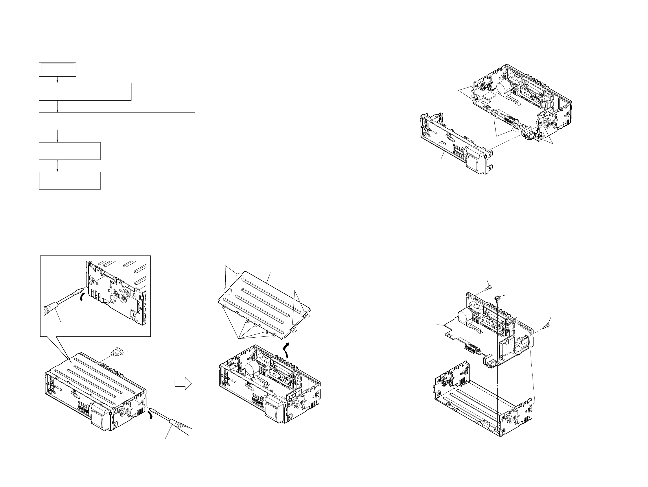
SECTION 3
DISASSEMBLY
DSX-A30/A30E
• This set can be disassembled in the order shown below.
3-1. DISASSEMBLY FLOW
SET
FRONT PANEL SECTION
Illustration of disassembly is omitted.
Note:
3-2. FUSE (BLADE TYPE) (AUTO FUSE) (10A/32V) (FU101), COVER
(Page 7)
3-3. SUB PANEL BLOCK
(Page 7)
3-4. MAIN BOARD
(Page 7)
3-3. SUB PANEL BLOCK
1 two claws
1 two claws
1 two claws
2 sub panel block
Note: Follow the disassembly procedure in the numerical order given.
3-2. FUSE (BLADE TYPE) (AUTO FUSE) (10A/32V) (FU101), COVER
3 two bosses
2 Insert a flathead screwdriver between the
cover and the chassis and raise the cover.
4 five claws
1 fuse (blade type) (auto fuse)
(10A/32V) (FU101)
5 cover
3 two bosses
3-4. MAIN BOARD
3 MAIN board
1 screw
(PTT2.6 u 8)
2 two ground point screws
(PTT2.6 u 6)
1 screw
(PTT2.6 u 8)
DSX-A30/A30E
2 Insert a flathead screwdriver between the
cover and the chassis and raise the cover.
77
DSX-A30/A30E
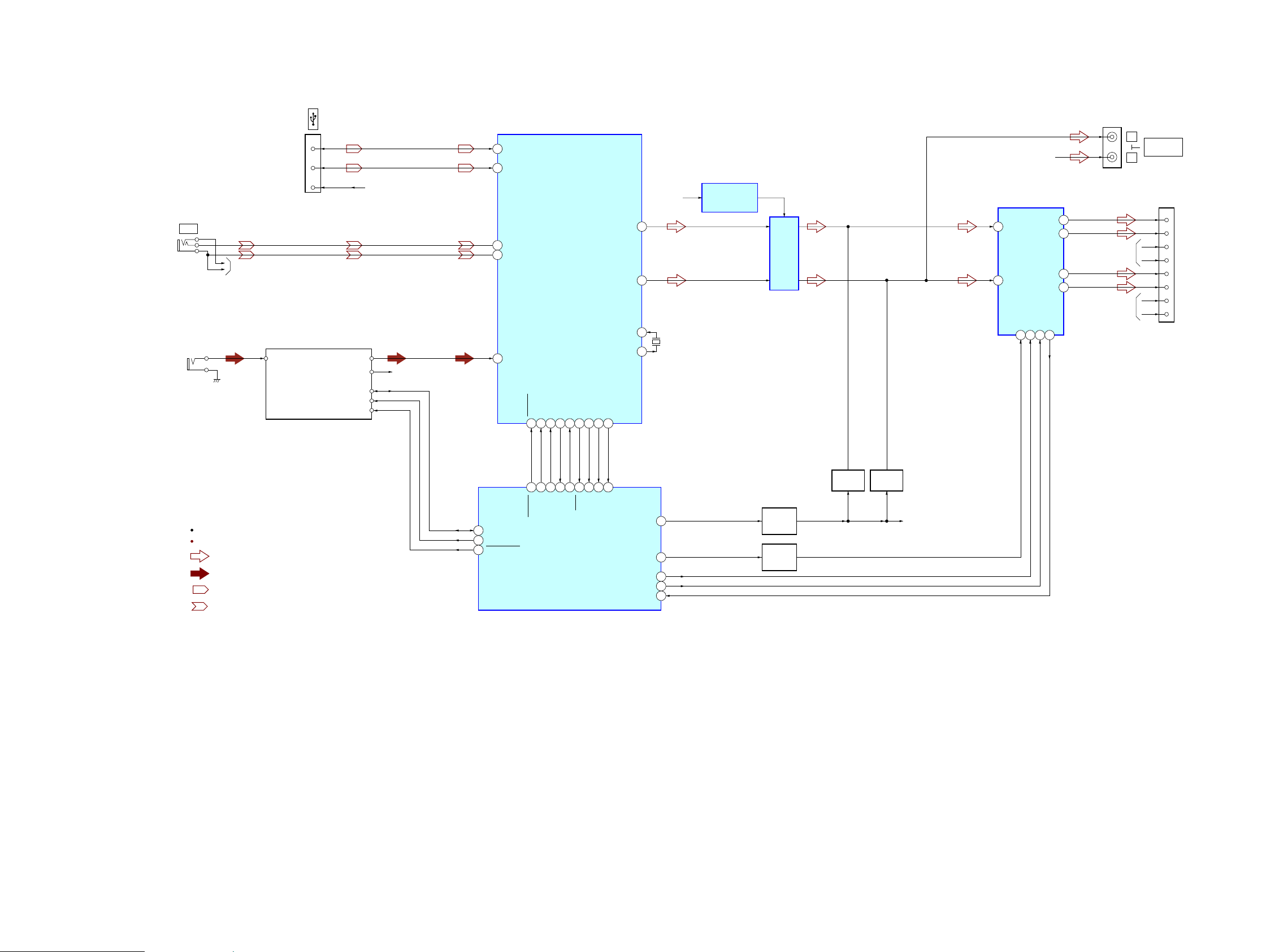
SECTION 4
DIAGRAMS
4-1. BLOCK DIAGRAM - MAIN Section -
CN201
3
D+
2
D–
1
J304
AUX
J303
(ANTENNA IN)
R-CH
TU251
TUX-DSP02 (TUNER UNIT)
RF_ANT_IN
VBUS
AUDIO_OUT_L
AUDIO_OUT_R
USB_VBUS
R-CH
69
68
13
14
9
UDP1
UDM1
L3_IN_P
L3_IN_N
L1_IN
USB CONTROLLER,
INPUT SELECTOR,
AUDIO DSP,
ELECTRICAL VOLUME
IC201
LFOUT
LROUT
X12IN
X12OUT
J302
L
REAR
R-CH
R-CH
R
AUDIO OUT
CN102 (1/2)
1
9
4
12
2
10
3
11
FL+
FL–
FR+
FR–
RL+
RL–
RR+
RR–
R-CH
CENTER VOLTAGE
+8.5V
1
2
74
X201
12MHz
75
GENERATOR
IC303
LINE AMP
IC302
IN_FL
12
IN-RL
11
POWER AMP
IC304
MUTE22STBY4AC_GND16OFFSET
FL+
RL+
5
FL-
3
9
RL-
7
25
R-ch is omitted due to same as L-ch.
SIGNAL PATH
: AUDIO
: TUNER
: USB
: AUX
SDA
SCL
RSTN
45 HIT2_SDA
46 HIT2_SCL
47 HIT2_RESET
RESETB
SIFCK52SIFDI53SIFCE
51
18
SIFDO
55
54
21
22
19
20
SDI
SCK
SDO
SYSRST
SYSTEM CONTROLLER
IC101 (1/2)
BUSYB
CMD_ERR
USB_IN
WDT_MON
56
57
60
61
MUTING
17
23
25
16
CE
BUSY
USB_IN
WDT_MON
CMD_ERR
AMP_MUTE
ATT
AMPSTB
BEEP
PIC_ERR
56
57
58
26
63
MUTING
CONTROL
Q109, 110
MUTING
SWITCH
Q304
Q305
MUTING
Q303
R-CH
DSX-A30/A30E
88
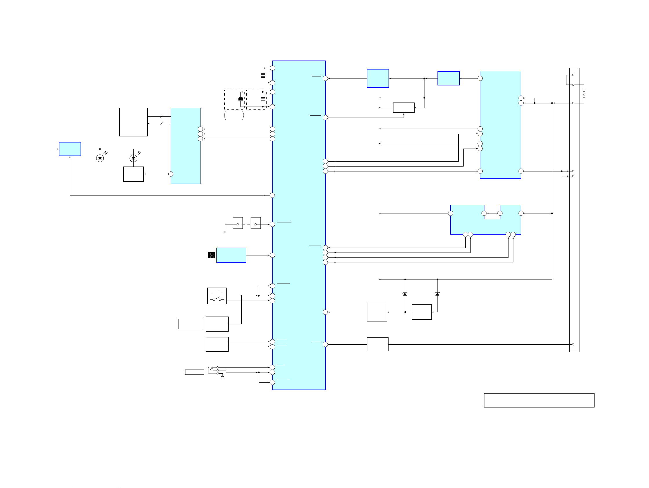
4-2. BLOCK DIAGRAM - DISPLAY/POWER SUPPLY Section -
B/U B+
+9V
REGULATOR
IC402
LED902 – 907
(Former type, A30E (New type)),
LED902, 903, 906 – 908
(A30 (New type)),
LSW901 – 906 (1/2)
(ILLUMINATION)
LIQUID CRYSTAL DISPLAY
LCD901
SEG1 – SEG32
COM1 – COM4
(LCD BACK LIGHT)
DIMMER
CONTROL
Q901
LIQUID CRYSTAL DISPLAY DRIVER
32
4
LED901
2
IC901
SEG1 – SEG32
COM1 – COM4
DIMMER
48
DI
47
CL
46
CE
X102
7.92MHz
Except
Saudi Arabia
X101
32.768kHz
X102
7.92MHz
(Saudi Arabia)
SYSTEM CONTROLLER
9
XOUT
8
XIN
11
OSCOUT
13
OSCIN
99
LCD_SO
100
LCD_CLK
98
LCD_CE
ILL_ON
59
IC101 (2/2)
RESET
SYS_ON
SYS_EN
AUDIO_EN
AMP_REM
DSX-A30/A30E
Ver. 1.3
REGULATOR
VDD (BACKUP5V)
5
REG 3.3V
15
REG_EN
10
AUDIO 8.5V
3
AUDIO_EN
2
AMP_EN
12
IC501
IC401
VCC1
VCC2
AMP12V
9
8
13
RESET
10
87
73
74
72
GENERATOR
BU +3.3V
SYS_3.3V
VDD_3.3V
+8.5V
SIGNAL
IC105
B+ SWITCH
Q106
+3.3V
REGULATOR
IC102
DC/DC CONVERTER
CN102 (2/2)
16
18
19
5
6
+B
FU101
AMP-REM
ANT-REM
PUSH ENTER/
SELECT
(VOLUME)
J101
REMOTE IN
REMOTE CONTROL
RECEIVER
LSW901 – 906 (2/2),
S901 – 906
(FRONT PANEL KEY)
ROTARY
ENCODER
S907 (1/2)
ROTARY
ENCODER
S907 (2/2)
CN001 CN103
IC902
USB_VBUS
1212
1
90
93
92
79
80
88
95
NOSE_SW
SIRCS2
KEYACK1
KEYIN0
KEYIN1
RE_IN0
RE_IN1
RCIN1
RC_IN0
FLT_USB
EN_USB
SYNC_OUT
EN_SYS
BU_IN
ACC_IN
50
48
24
51
B/U B+
D106
BACK UP
66
55
VOLTAGE
DETECT
Q101, 104
ACCESSORY
CHECK
Q106
BATTERY
CHECK
Q103
5 USBOUT
9
D107
FLT_USB
12
EN_USB
7
2LXUSBIN
3
VIN
SYNC8EN_SYS
4
ACC
7
DSX-A30/A30E
89
KEYACK0
Note: Refer to “NEW/FORMER DISCRIMINATION”
(page 2 on supplement-1) for New/Former types.
99
DSX-A30/A30E
Ver. 1.2
THIS NOTE IS COMMON FOR PRINTED WIRING BOARDS AND SCHEMATIC DIAGRAMS.
(In addition to this, the necessary note is printed in each block.)
For Printed Wiring Boards.
Note:
• X : Parts extracted from the component side.
• Y : Parts extracted from the conductor side.
• f : Internal component.
• : Pattern from the side which enables seeing.
(The other layers’ patterns are not indicated.)
Caution:
Pattern face side:
(Conductor Side)
Parts face side:
(Component Side)
• Indication of transistor.
C
Q
B
E
• Abbreviation
AR : Argentina model
EA : Saudi Arabia model
IND : Indian model
MX : Mexican model
RU : Russian model
Note: When the MAIN board in this unit is replaced, the destination
setting is necessary. Refer to “NOTE THE MAIN BOARD OR
SYSTEM CONTROLLER (IC101) REPLACING” (page 4).
Parts on the pattern face side seen
from the pattern face are indicated.
Parts on the parts face side seen from
the parts face are indicated.
These are omitted.
For Schematic Diagrams.
Note:
• All capacitors are in μF unless otherwise noted. (p: pF)
50 WV or less are not indicated except for electrolytics
and tantalums.
• All resistors are in and 1/4 W or less unless otherwise
specifi ed.
• f : internal component.
• C : panel designation.
• A : B+ Line.
• Power voltages is dc 14.4V and fed with regulated dc
power supply from ACC and BATT cords.
• Voltages and waveforms are dc with respect to ground
under no-signal (detuned) conditions.
no mark
• Voltages are taken with a VOM (Input impedance 10 M).
Voltage variations may be noted due to normal production
• Waveforms are taken with a oscilloscope.
Voltage variations may be noted due to normal production
• Circled numbers refer to waveforms.
• Signal path.
F : AUDIO
f : TUNER
d : USB
E : AUX
• Abbreviation
AR : Argentina model
EA : Saudi Arabia model
IND : Indian model
MX : Mexican model
RU : Russian model
: TUNER
tolerances.
tolerances.
Note: When the MAIN board in this unit is replaced, the destination
setting is necessary. Refer to “NOTE THE MAIN BOARD OR
SYSTEM CONTROLLER (IC101) REPLACING” (page 4).
• Waveforms
– MAIN Board –
IC101 9 (XOUT)
1
1 V/DIV, 20 Ps/DIV
IC101 qa (OSCOUT)
2
126 ns
1 V/DIV, 50 ns/DIV
IC501 1 (BST), 2 (LX)
3
2.4 Ps
5 V/DIV, 1 Ps/DIV
IC501 8 (SYNC)
4
30.5 Ps
2.5 Vp-p
3.5 Vp-p
18.2 Vp-p
– KEY Board –
IC901 rf (OSC)
qa
28.4 Ps
1 V/DIV, 10 Ps/DIV
2.6 Vp-p
DSX-A30/A30E
IC201 ug (X12OUT)
5
1010
2.4 Ps
3.3 Vp-p
1 V/DIV, 1 Ps/DIV
3.2 Vp-p
83 ns
1 V/DIV, 50 ns/DIV
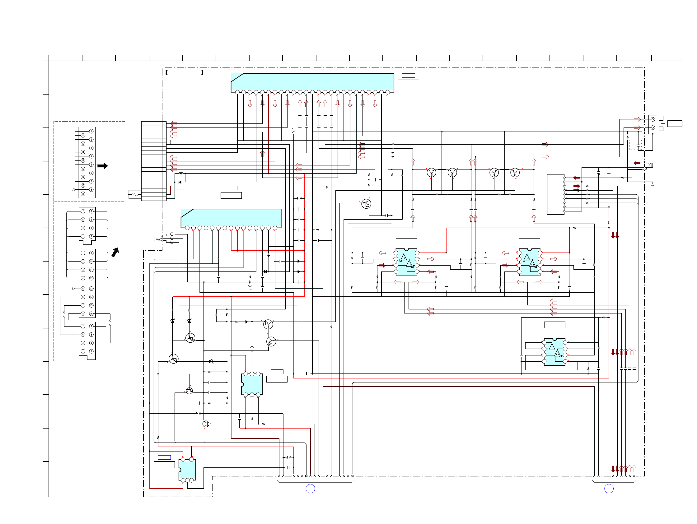
DSX-A30/A30E
Ver. 1.2
4-3. SCHEMATIC DIAGRAM - MAIN Board (1/3) -
A
B
C
D
E
F
G
H
K
L
M
I
J
(E, EA, MX, IND)
FRONT LCH+
FRONT LCH-
REAR LCH+
REAR LCHREAR RCH+
REAR RCH-
FRONT RCH+
FRONT RCH-
REM OUT
MAX 0.4A
ACC
GND
BATT
(AEP, RU, UK, AR)
AMP REM
MAX 0.3A
AMT REM
AMT REM
PW1
TO
CN102
FU101
10A
32V
RL+
FL+
FR+
RR+
RL+
ACC
ACC
RL-
FL-
FR-
RR-
TO
PW1
CN102
FL-FL+
RL-
RR-RR+
FR-FR+
BATTGND
GND
BATT
J101
(REMOTE IN)
MAIN BOARD (1/3)
CN102
16P
1FL+
2RL+
3RR+
4FR+
5AMP-REM
6ANT-REM
7ACC
8GND
9FL–
10RL–
11RR–
12FR–
13TEL-ATT
L401
14ILL
140uH
15TEST
D402
16+B
GN1G
17+B
(AEP, UK)
18+B
19+B
FB103
FB102
FB101
AUDIO_EN
SYS_EN
AMP_REM
R106
1k
D106
RKZ7.5B2KGP1
6.5
6.5
BATTERY CHECK
0
Q101
DRC5144E0L
Q104
2SC4154TP-1EF
3.3
2SC3052EF-T1-LEF
ACCESSORY CHECK
R105
220k
BUIN
4.9 3.3
IC B/D
IC102
+3.3V REGULATOR
IC102
MM1836A33NRE
4.9
D107
DRC5114E0L
5
VIN
CONT2GND3NOISE
1
• See page 20 for IC Block Diagrams.
5
TAB2PW_GND2(FL)3FL–4STBY5FL+6VCC27RL–8PW_GND1(RL)9RL+10RIPPLE11IN_RL12IN_FL13PRE_GND(BEEP?)14IN_FR15IN_RR16AC_GND17RR+18PW_GND3(RR)19RR–20VCC121FR+22MUTE23FR–24PW_GND4(FR)25OFFSET
1
IC B/D
IC401
REGULATOR
IC401
LV56831P-E
NC2AUDIO_EN3AUDIO 8.5V4NC5VDD(BACKUP5V)6IKVDD7NC8VCC9VCC110REG_EN11IKREG12AMP_EN13AMP12V14GND15REG 3.3V
1
3.3
8.5
4.9
R107
1k
RKZ18B2KGP1
0
Q103
0
Q106
4
C110
0.01
C106
1000
6.3V
ACC_IN
BACK UP VOLTAGE DETECT
VOUT
C403
R114
10k
D114
RKZ18B2KGP1
R111
47k
C101
0.47
C102
0.47
R112
4.7k
0
10
0.5
Q101, 104
4.9
R403
10k
R117
10k
R116
47k
3.3
14.1
14.1
R404
10k
C411
220
16V
R118
22
D116
DA2J10100L
C105
47
25V
14.1
6
1
8.9
C409
1
7
2.4
TO
CN301
0
3.3
C407
10
C410
10
13.9
MUTING CONTROL
4
5
NC
VIN
VSS
VOUT2VSS3ON/OFF
3.3
R407
100k
R405
7
7
12
D405
D404
GN1G
Q109
DRA5114E0L
13.9
Q109, 110
10k
14.1
GN1G
IC402
+9V REGULATOR
S-1142B90I-E6T1U
7
3.3
C408
0
DRC5114Y0L
IC B/D
IC402
9
101
13
142 1512
168
176113
18 194
IC B/D
IC304
POWER AMP
IC304
7
7
7
777
7
7
7
8.5
1
1
C3201C322
C3231C321
C319
22
16V
C401
3300
16V
C406
1
C412
0.22
C330
0.22
C318
0.22
D403
GN1G
10
D401
GN1G
C404
1
0
Q110
C122
100
16V
C119
1
1
3
2
16
1
1
C324
C326
C328
1
1
1
1
C327
C325
C349
R334
10k
R336
150
C329
47p
R335
47k
C340
1
9
8
6
5274
7
10
MAIN
BOARD
(Page 12) (Page 13)
1
(2/3)
111914
13
14.1
Q304
DRC5114E0L
MUTING
SWITCH
R301
12k
R302
10k
7
4.1
R356
C332
100
1
R337
220
4.1
0
C331
C301
220p
R305
4.7k
R304
100k
LV47011P-E
3.3
J302
2P
L
REAR
AUDIO OUT
R
R339
R259
0
C231 1
24
23
221225
MAIN
BOARD
(3/3)
C233 1
(EA)
HIT2_RST
HIT2_SCL
HIT2_SDA
C237 1
0
C355
0.1
J303
(ANTENNA IN)
CAM251
(CHASSIS)
C239 1
26
R322
220
220R323
220R324
R325
220
R346
R338
4.7k
100
R326
220
C310
3
3
3
IC301
BA4560RFVM-TR
1
2
3
4
V-
LINE AMP
IC301
10
0.1
Q301
LTC614TUFP8T106
MUTING MUTING MUTING MUTING
0000
0000
8.4
8
V+
3
7
3
6
3
5
R307
100k
R327
10k
R306
4.7k
C302
0.1
Q302
LTC614TUFP8T106
R328
10k
C303
220p
R329
220
C313
10
R308
12k
R309
10k
R330
220
C314
R310
12k
R311
10k
10
Q303
LTC614TUFP8T106
C304
220p
R313
R312
Q305
LTC614TUFP8T106
R331
R332
10k
10k
4.7k
100k
C306
3
3
3
10
IC302
BA4560RFVM-TR
1
2
3
4
V-
R333
220
C317
10
LINE AMP
IC302
TU251
TUX-DSP02
(TUNER UNIT)
RF_ANT_IN
RF_GND
AUDIO_OUT_L
AUDIO_OUT_R
POWER_GND
8.4
8
V+
3
7
3
6
3
5
R315
100k
IC303
CENTER VOLTAGE GENERATOR
IC303
BA4560RFVM-TR
3
1
3
2
3
3
4
V-
C255
C257
0.1
47
0
1
2
2
3
2
4
3.3
RSTN
5
2.6
SCL
6
2.4
SDA
7
8.4
+8.5V
8
9
R318
R314
4.7k
C305
10
8.4
8
V+
3
7
3
6
3
5
25V
R252
0
0R257
0R260
0R262
0R263
L251
4.7uH
10
R319
C308
12k
220p
R320
10k
R321
10
R316
10k
C309
R317
10
12k
18
2
DSX-A30/A30E
1111
 Loading...