

Sony DSX-A30 SERVICE MANUAL
DSX-A30
SERVICE MANUAL
Ver. 1.0 2011.12
• This model is not equipped with a mechanism deck.
SPECIFICATIONS
Tuner section
(E, Mexican and Indian models) (Saudi Arabia model)
FM
Tuning range:
87.5 – 108.0 MHz (at 50 kHz step)
87.5 – 108.0 MHz (at 100 kHz step)
87.5 – 107.9 MHz (at 200 kHz step)
FM tuning step:
50 kHz/100 kHz/200 kHz switchable
Antenna (aerial) terminal:
External antenna (aerial) connector
Intermediate frequency: 25 kHz
Usable sensitivity: 8 dBf
Selectivity: 75 dB at 400 kHz
Signal-to-noise ratio: 80 dB (stereo)
Separation: 50 dB at 1 kHz
Frequency response: 20 – 15,000 Hz
AM
Tuning range:
531 – 1,602 kHz (at 9 kHz step)
530 – 1,710 kHz (at 10 kHz step)
AM tuning step:
9 kHz/10 kHz switchable
Antenna (aerial) terminal:
External antenna (aerial) connector
Intermediate frequency:
9,124.5 kHz or 9,115.5 kHz/4.5 kHz
(at 9 kHz step)
9,115 kHz or 9,125 kHz/5 kHz (at 10 kHz step)
Sensitivity: 26 μV
Tuner section
FM
Tuning range: 87.5 – 108.0 MHz
Antenna (aerial) terminal:
External antenna (aerial) connector
Intermediate frequency: 25 kHz
Usable sensitivity: 8 dBf
Selectivity: 75 dB at 400 kHz
Signal-to-noise rat io: 80 dB (stereo)
Separation: 50 dB at 1 kHz
Frequency response: 20 – 15,000 Hz
MW
Tuning range: 531 – 1,602 kHz
Antenna (aerial) terminal:
External antenna (aerial) connector
Intermediate frequency:
9,124.5 kHz or 9,115.5 kHz/4.5 kHz
y: 26 μV
Sensitivit
SW
Tuning range:
SW1: 2,940 – 7,735 kHz
SW2: 9,500 – 18,135 kHz
(except for 10,140 – 11,575 kHz)
Antenna (aerial) terminal:
External antenna (aerial) connector
Intermediate frequency:
9,124.5 kHz or 9,115.5 kHz/4.5 kHz
Sensitivity: 26 μV
E Model
USB Player section
Interface: USB (Full-speed)
Maximum current: 500 mA
Power amplier section
Output: Speaker outputs
Speaker impedance: 4 – 8 ohms
Maximum power output: 50 W × 4 (at 4 ohms)
General
Outputs:
Audio outputs terminal (rear)
Power antenna (aerial)/Power amplier control
terminal (R
Inputs:
Remote controller input terminal
Antenna (aerial) input terminal
AUX input jack (stereo mini jack)
USB signal input connector
Power requirements: 12 V DC car battery
(negative ground (earth))
Dimensions: Approx. 178 × 50 × 120 mm
(7
Mounting dimensions: Approx. 182 × 53 × 103 mm
(7
Mass: Approx. 0.7 kg (1 lb 9 oz)
Supplied accessories:
Remote commander: RM-X211
Parts for installation and connections (1 s
Design and specications are subject to change
without notice.
EM OUT)
1
/8 × 2 × 47/8 in) (w/h/d)
1
/4 × 21/8 × 41/8 in) (w/h/d)
et)
9-893-394-01
2011L33-1
2011.12
©
E, Mexican, Indian models
FM/AM DIGITAL MEDIA PLAYER
Saudi Arabia model
FM/MW/SW DIGITAL MEDIA PLAYER
Sony Corporation
Published by Sony Techno Create Corporation

DSX-A30
Windows Media is either a registered
trademark or trademark of Microso
Corporation in the United States and/or
other countries.
is product contains technology subject
to certain intellectual property rights of
Microso. Use or distribution of this
technology outside of this product is
prohibited without the appropriate
license(s) from Microso.
MPEG Layer-3 audio coding technology
and patents licensed from Fraunhofer IIS
and omson.
TABLE OF CONTENTS
1. SERVICING NOTES ............................................. 3
2. GENERAL .................................................................. 5
3. DISASSEMBLY
3-1. Disassembly Flow ........................................................... 7
3-2. Fuse (Blade Type) (Auto Fuse) (10A/32V) (FU101),
Cover ............................................................................... 7
3-3. Sub Panel Block .............................................................. 7
3-4. MAIN Board ................................................................... 7
4. DIAGRAMS
4-1. Block Diagram - MAIN Section - ................................... 8
4-2. Block Diagram
- DISPLAY/POWER SUPPLY Section - ........................ 9
4-3. Schematic Diagram - MAIN Board (1/3) - ..................... 11
4-4. Schematic Diagram - MAIN Board (2/3) - ..................... 12
4-5. Schematic Diagram - MAIN Board (3/3) - ..................... 13
4-6. Printed Wiring Board - MAIN Board
(Component Side) (E, Mexican and Indian models) - .... 14
4-7. Printed Wiring Board - MAIN Board
(Conductor Side) (E, Mexican and Indian models) - ...... 15
4-8. Printed Wiring Board - MAIN Board
(Component Side) (Saudi Arabia model) - ..................... 16
4-9. Printed Wiring Board - MAIN Board
(Conductor Side) (Saudi Arabia model) - ....................... 17
4-10. Printed Wiring Board - KEY Board -.............................. 18
4-11. Schematic Diagram - KEY Board - ................................ 19
5. EXPLODED VIEWS
5-1. Main Section ................................................................... 25
5-2. Front Panel Section ......................................................... 26
6. ELECTRICAL PARTS LIST .............................. 27
Accessories are given in the last of the electrical parts list.
NOTES ON CHIP COMPONENT REPLACEMENT
• Never reuse a disconnected chip component.
• Notice that the minus side of a tantalum capacitor may be dam-
aged by heat.
2

SECTION 1
SERVICING NOTES
DSX-A30
UNLEADED SOLDER
Boards requiring use of unleaded solder are printed with the leadfree mark (LF) indicating the solder contains no lead.
(Caution: Some printed circuit boards may not come printed with
the lead free mark due to their particular size)
: LEAD FREE MARK
Unleaded solder has the following characteristics.
• Unleaded solder melts at a temperature about 40 °C higher
than ordinary solder.
Ordinary soldering irons can be used but the iron tip has to be
applied to the solder joint for a slightly longer time.
Soldering irons using a temperature regulator should be set to
about 350 °C.
Caution: The printed pattern (copper foil) may peel away if
the heated tip is applied for too long, so be careful!
• Strong viscosity
Unleaded solder is more viscous (sticky, less prone to fl ow)
than ordinary solder so use caution not to let solder bridges
occur such as on IC pins, etc.
• Usable with ordinary solder
It is best to use only unleaded solder but unleaded solder may
also be added to ordinary solder.
NOTE FOR THE 15-PIN CONNECTOR (CN001)
Do not use alcohol to clean the 15-pin connector (CN001) connecting the front panel with the main body.
Do not touch the connector directly with your bare hand. Poor contact may be caused.
ABOUT CHECKING THE OPERATION
When checking the operation of this unit, connect a USB device
to this unit.
Refer to the support site written in the operating instruction for the
details about the compatibility of a USB device.
3
DSX-A30
NOTE THE MAIN BOARD OR SYSTEM CONTROLLER
(IC101) REPLACING
When the MAIN board or system controller (IC101) is replaced,
the destination setting is necessary.
1. Destination Setting
Set destination according to the procedure below.
1-1. Setting the Destination Code
1. In the state of source off (the clock is displayed), enter the
test mode by pressing the buttons on the remote commander in
order of the [4] t [5] t [6] (press only the [6] button for two
seconds).
2. In the state in which the system controller version is displayed
on the liquid crystal display, enter the destination setting mode
by pressing the buttons on the main unit in order of the [SEEK
+] t [SEEK –] t [PUSH ENTER/SELECT].
3. Input the alphanumeric character of 6 digits of “F XXXXXX”
displayed on the liquid crystal display, and execute the destination setting.
Note: Refer to following “1-3. Entering the Destination Code” for opera-
tion method.
4. The resetting operation is executed by pressing the [SOURCE/
OFF] button for 1 second after the setting ends, and the unit
returns to the normal condition.
1-2. Display in Destination Setting Mode
OP0OP2 OP1OP3OP4OP5
8 digits
F
XXXXXX
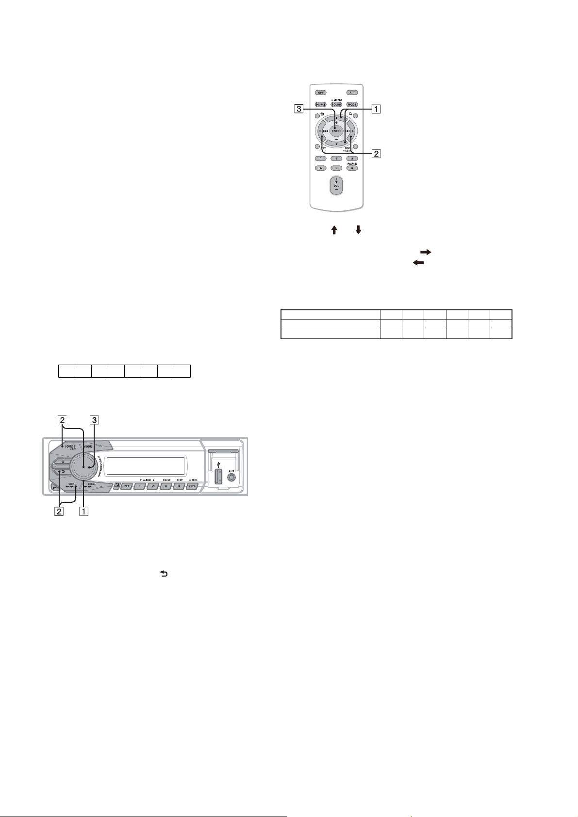
1-3. Entering the Destination Code
• Method of operation by main unit
1. Rotate the control dial, and select the alphanumeric character
of “0 to F”.
2. The digit advances by pressing the [PUSH ENTER/SELECT]
or [SEEK +] button.
The digit returns by pressing the [ ] or [SEEK –] button.
3. The setting is completed by pressing the [PUSH ENTER/
SELECT] button, and the initialization operation is done.
• Method of operation by remote commander
1. Press the [ ] or [ ] button, and select the alphanumeric character of “0 to F”.
2. The digit advances by pressing the [ ] button.
The digit returns by pressing the [ ] button.
3. The setting is completed by pressing the [ENTER] button, and
the initialization operation is done.
1-4. Destination Code
Destination OP5 OP4 OP3 OP2 OP1 OP0
E, Mexican, Indian 0 0 4 A 0 0
Saudi Arabia 0 0 4 A 0 4
2. Confi rmation After Destination Setting
Execute the following operation after completing the destination
setting, and confi rm a correct destination was set.
Destination setting checking method:
1. In the state of source off (the clock is displayed on the liquid
crystal display), enter the test mode by pressing the buttons on
the remote commander in order of the [4] t [5] t [6] (press
only the [6] button for two seconds).
2. In the state in which the system controller version is displayed
on the liquid crystal display, enter the destination setting value
display mode by pressing the [DSPL] button on the main unit.
3. Confi rm the alphanumeric character of 6 digits of “F
XXXXXX” displayed in liquid crystal display is an value correctly input.
4. The resetting operation is executed by pressing the [SOURCE/
OFF] button on the main unit for 1 second after the confi rming
ends, and the unit returns to the normal condition.
4

DSX-A30
SECTION 2
GENERAL
*1 Speaker impedance: 4 – 8 ohms × 4
2
*
RCA pin cord (not supplied).
3
*
Black
Negro
Red
Rojo
Yellow
Amarillo
REMOTE
IN
3
*
Separate adaptor may be required.
2
A
REAR
AUDIO OUT
Left
Izquierdo
from car antenna (aerial)
desde la antena del automóvil
B
Right
Derecho
1
*
Left
Izquierdo
Right
Derecho
*
Blue/white striped
REM OUT
Max. supply current 0.4 A
Corriente máx. de alimentación de 0,4 A
Con rayas azules y blancas
White
Blanco
White/black striped
Con rayas blancas y negras
Gray
Gris
Gray/black striped
Con rayas grises y negras
Green
Verde
Green/black striped
Con rayas verdes y negras
Purple
Morado
Purple/black striped
Con rayas moradas y negras
REAR
AUDIO OUT
Fuse (10 A)
Fusible (10 A)
This section is extracted
from instruction manual.
1
Impedancia de los altavoces: de 4 a 8 Ω × 4
*
2
*
Cable con terminales RCA (no suministrado).
3
*
Puede requerirse un adaptador independiente.
ACC
BATTERY
Cautions
is unit is designed for negative ground (earth) 12 V
DC operation only.
Do not get the leads under a screw, or caught in moving
parts (e.g. seat railing).
Before making connections, turn the car ignition off to
avoid short circuits.
Connect the yellow and red power input leads only
after all other leads have been connected.
Run all ground (earth) leads to a common ground
(earth) point.
Be sure to insulate any loose unconnected leads with
electrical tape for safety.
Notes on the power supply lead (yellow)
When connecting this unit in combination with other
stereo components, the connected car circuit’s rating
must be higher than the sum of each component’s fuse.
When no car circuits are rated high enough, connect
the unit directly to the battery.
Connection example
Notes
Be sure to connect the ground (earth) lead before connecting the
amplier.
The alarm will only sound if the built-in amplier is used.
Connection diagram
To a metal surface of the car
First connect the black ground (earth) lead, then connect the
yellow, and red power supply leads.
To the power antenna (aerial) control lead or
power supply lead of antenna (aerial) booster
Notes
It is not necessary to connect this lead if there is no power
antenna (aerial) or antenna (aerial) booster, or with a
manually-operated telescopic antenna (aerial).
When your car has a built-in FM/AM antenna (aerial) in the rear/
side glass, see “Notes on the control and power supply leads.”
To AMP REMOTE IN of an optional power
amplier
This connection is only for ampliers. Connecting any other system
may damage the unit.
To the +12 V power terminal which is energized
in the accessory position of the ignition key
switch
Notes
If there is no accessory position, connect to the +12 V power
(battery) terminal which is energized at all times.
Be sure to connect the black ground (earth) lead to a metal
surface of the car rst.
When your car has a built-in FM/AM antenna (aerial) in the rear/
side glass, see “Notes on the control and power supply leads.”
To the +12 V power terminal which is energized
at all times
Be sure to connect the black ground (earth) lead to a metal surface
of the car rst.
Notes on the control and power supply leads
REM OUT lead (blue/white striped) supplies +12 V DC when you turn
on the unit.
When your car has built-in FM/AM antenna (aerial) in the rear/side
glass, connect REM OUT lead (blue/white striped) or the accessory
power supply lead (red) to the power terminal of the existing antenna
(aerial) booster. For details, consult your dealer.
A power antenna (aerial) without a relay box cannot be used with this
unit.
Memory hold connection
When the yellow power input lead is connected, power will always be
supplied to the memory circuit even when the ignition switch is turned
o.
Notes on speaker connection
Before connecting the speakers, turn the unit o.
Use speakers with an impedance of 4 to 8 ohms, and with adequate
power handling capacities to avoid its damage.
Do not connect the speaker terminals to the car chassis, or connect the
terminals of the right speakers with those of the left speaker.
Do not connect the ground (earth) lead of this unit to the negative (–)
terminal of the speaker.
Do not attempt to connect the speakers in parallel.
Connect only passive speakers. Connecting active speakers (with
built-in ampliers) to the speaker terminals may damage the unit.
To avoid a malfunction, do not use the built-in speaker leads installed
in your car if the unit shares a common negative (–) lead for the right
and left speakers.
Do not connect the unit’s speaker leads to each other.
Note on connection
If speaker and amplier are not connected correctly, “ERROR-01” appears
in the display. In this case, make sure the speaker and amplier are
connected correctly.
Precauciones
Esta unidad ha sido diseñada para alimentarse sólo con
cc de 12 V de masa negativa.
No coloque los cables debajo de ningún tornillo, ni los
aprisione con partes móviles (p. ej. los rieles del
asiento).
Antes de realizar las conexiones, apague el automóvil
para evitar cortocircuitos.
Conecte los cables de fuente de alimentación amarillo
y rojo solamente después de haber conectado los
demás.
Conecte todos los cables de conexión a masa a un
punto común.
Por razones de seguridad, asegúrese de aislar con cinta
aislante los cables sueltos que no estén conectados.
Notas sobre el cable de fuente de alimentación
(amarillo)
Cuando conecte esta unidad en combinación con otros
componentes estéreo, la capacidad nominal del circuito
conectado del automóvil debe ser superior a la suma del
fusible de cada componente.
Si no hay circuitos del automóvil con capacidad
nominal suficientemente alta, conecte la unidad
directamente a la batería.
Nota
Antes de instalar la unidad, compruebe que los enganches de ambos
lados del soporte
estén doblados hacia adentro 2 mm. Si no lo están
o están doblados hacia afuera, la unidad no se instalará correctamente
y puede saltar.
Ejemplo de conexiones
Notas
Asegúrese de conectar primero el cable de conexión a masa antes de
realizar la conexión del amplicador.
La alarma sonará únicamente si se utiliza el amplicador incorporado.
Diagrama de conexión
A una supercie metálica del automóvil
Conecte primero el cable de conexión a masa negro, y después los
cables amarillo y rojo de fuente de alimentación.
Al cable de control de la antena motorizada o al
cable de fuente de alimentación del
amplicador de señal de la antena
Notas
Si no se dispone de antena motorizada ni de amplicador de
señal de la antena, o se utiliza una antena telescópica accionada
manualmente, no será necesario conectar este cable.
Si el automóvil tiene una antena de FM/AM incorporada en el
cristal trasero o lateral, consulte “Notas sobre los cables de
control y de fuente de alimentación”.
A AMP REMOTE IN de un amplicador de
potencia opcional
Esta conexión es sólo para amplicadores. La conexión de cualquier
otro sistema puede dañar la unidad.
Al terminal de alimentación de +12 V que recibe
energía en la posición de accesorio del
interruptor de encendido
Notas
Si no hay posición de accesorio, conéctelo al terminal de
alimentación (batería) de +12 V que recibe energía sin
interrupción.
Asegúrese de conectar primero el cable de conexión a masa
negro a una supercie metálica del automóvil.
Si el automóvil tiene una antena de FM/AM incorporada en el
cristal trasero o lateral, consulte “Notas sobre los cables de
control y de fuente de alimentación”.
Al terminal de alimentación de +12 V que recibe
energía sin interrupción
Asegúrese de conectar primero el cable de conexión a masa negro a
una supercie metálica del automóvil.
Notas sobre los cables de control y de fuente de alimentación
El cable REM OUT (rayado azul y blanco) suministra cc +12 V al
encender la unidad.
Si el automóvil dispone de una antena de FM/AM incorporada en el
cristal trasero o lateral, conecte el cable REM OUT (rayado azul y
blanco) o el cable de fuente de alimentación auxiliar (rojo) al terminal
de alimentación del amplicador de señal de la antena existente. Para
obtener más detalles, consulte a su distribuidor.
Con esta unidad no es posible utilizar una antena motorizada sin caja
de relé.
Conexión para protección de la memoria
Si conecta el cable de fuente de alimentación amarillo, el circuito de la
memoria recibirá siempre alimentación, aunque apague el interruptor
de encendido.
Notas sobre la conexión de los altavoces
Antes de conectar los altavoces, desconecte la alimentación de la
unidad.
Utilice altavoces con una impedancia de 4 a 8 Ω con la capacidad de
potencia adecuada para evitar que se dañen.
No conecte los terminales de altavoz al chasis del automóvil, ni
conecte los terminales del altavoz derecho con los del izquierdo.
No conecte el cable de conexión a masa de esta unidad al terminal
negativo (–) del altavoz.
No intente conectar los altavoces en paralelo.
Conecte solamente altavoces pasivos. Si conecta altavoces activos
(con amplicadores incorporados) a los terminales de altavoz, puede
dañar la unidad.
Para evitar fallas de funcionamiento, no utilice los cables de altavoz
incorporados instalados en el automóvil si la unidad comparte un
cable negativo común (–) para los altavoces derecho e izquierdo.
No conecte los cables de altavoz de la unidad entre sí.
Nota sobre la conexión
Si el altavoz y el amplicador no están conectados correctamente,
aparecerá “ERROR-01” en la pantalla. Si es así, compruebe la conexión
de ambos dispositivos.
5
DSX-A30
Claws
Uñas
2
size
5 × max. 8 mm
7
/32 × max. 5/16 in)
(
Tamaño
5 × 8 mm máx.
size
5 × max. 8 mm
7
/32 × max. 5/16 in)
(
Tamaño
5 × 8 mm máx.
Face the hook inwards.
El gancho debe
encontrarse en la parte
interior.
Bracket
Soporte
Existing parts supplied with your car
Piezas existentes suministradas con su automóvil
Dashboard
Tablero
1
1 23
A TOYOTA B NISSAN
size
5 × max. 8 mm
7
/32 × max. 5/16 in)
(
Tamaño
5 × 8 mm máx.
Bracket
Soporte
Existing parts supplied with your car
Piezas existentes suministradas con su automóvil
to dashboard/center console
al tablero o consola central
Bracket
Soporte
to dashboard/center console
al tablero o consola central
Bracket
Soporte
size
5 × max. 8 mm
7
/32 × max. 5/16 in)
(
Tamaño
5 × 8 mm máx.
AB
Precautions
Choose the installation location carefully so that the
unit will not interfere with normal driving operations.
Avoid installing the unit in areas subject to dust, dirt,
excessive vibration, or high temperatures, such as in
direct sunlight or near heater ducts.
Use only the supplied mounting hardware for a safe and
secure installation.
Mounting angle adjustment
Adjust the mounting angle to less than 45°.
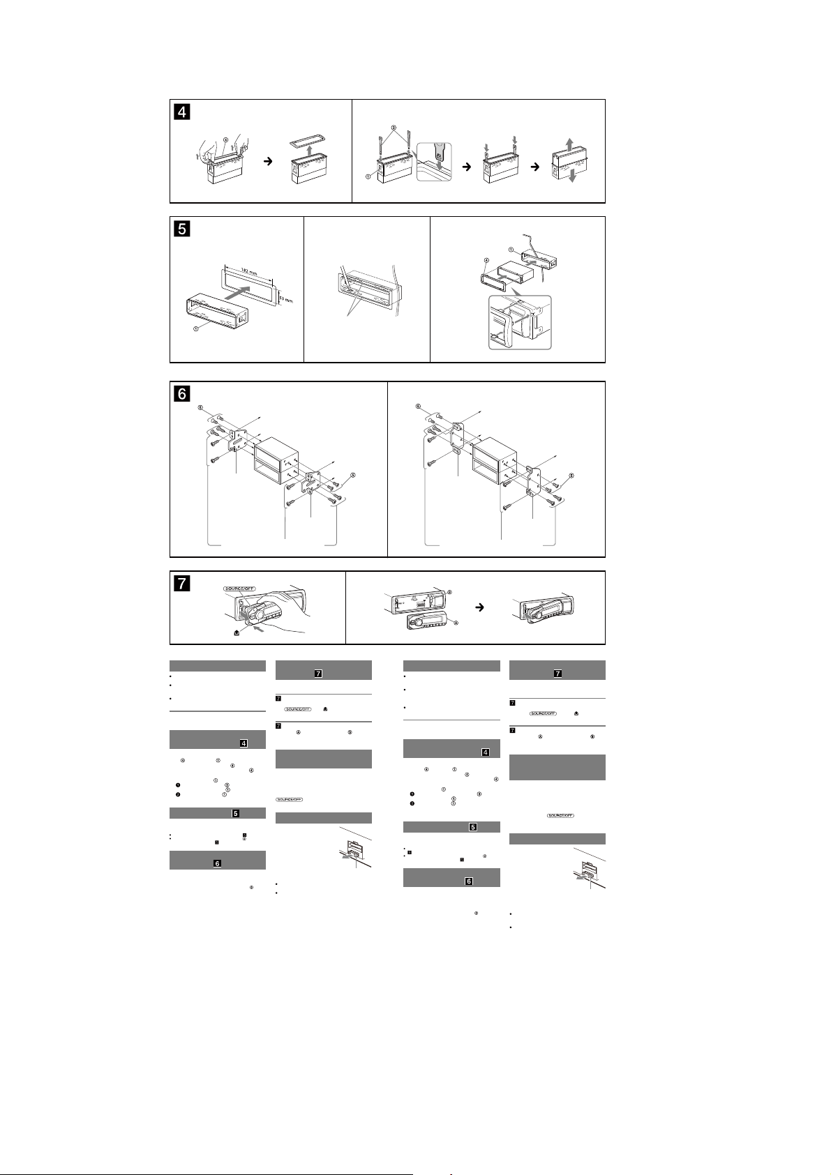
Removing the protection
collar and the bracket
Before installing the unit, remove the protection
and the bracket from the unit.
collar
Remove the protection collar .
1
Pinch both edges of the protection collar , then
pull it out.
Remove the bracket .
2
Insert both release keys together between
the unit and the bracket
Pull down the bracket , then pull up the unit
to separate.
until they click.
Mounting example
Installation in the dashboard
Notes
Bend these claws outward for a tight t, if necessary ( -2).
Make sure that the 4 catches on the protection collar are properly
engaged in the slots of the unit (
Mounting the unit in a
Japanese car
You may not be able to install this unit in some makes of
Japanese cars. In such a case, consult your Sony dealer.
Note
To prevent malfunction, install only with the supplied screws
-3).
.
How to detach and attach the
front panel
Before installing the unit, detach the front panel.
-A To detach
Before detaching the front panel, be sure to press and
. Press and pull it off towards
hold
you.
-B To attach
Engage part of the front panel with part of the unit,
as illustrated, and push the le side into position until it
clicks.
Warning if your car’s ignition
has no ACC position
Be sure to set the Auto Off function. For details, see the
supplied Operating Instructions.
e unit will shut off completely and automatically in the
set time aer the unit is turned off, which prevents
battery drain.
If you do not set the Auto Off function, press and hold
until the display disappears each time
you turn the ignition off.
Fuse replacement
When replacing the fuse, be sure to
use one matching the amperage
rating stated on the original fuse. If
the fuse blows, check the power
connection and replace the fuse. If
the fuse blows again after
replacement, there may be an
internal malfunction. In such a case,
consult your nearest Sony dealer.
Notes on the tuning step
For how to set the tuning step, see the supplied
Operating Instructions.
If replacing the car battery or changing the connections,
the tuning step setting will be erased.
Fuse (10 A)
Precauciones
Elija cuidadosamente el lugar de montaje de forma que
la unidad no interera con las funciones normales de
conducción.
Evite instalar la unidad donde pueda quedar expuesta a
polvo, suciedad, vibraciones excesivas o altas
temperaturas, por ejemplo, a la luz solar directa o cerca
de conductos de calefacción.
Para realizar una instalación segura y rme, utilice
solamente elementos de instalación suministrados.
Ajuste del ángulo de montaje
Ajuste el ángulo de montaje a menos de 45°.
Extracción del marco de
protección y del soporte
Antes de instalar la unidad, retire el marco de
y el soporte de la misma.
protección
Retire el marco de protección .
1
Apriete ambos bordes del marco de protección
y, a continuación, tire de él hacia fuera.
Retire el soporte .
2
Inserte ambas llaves de liberación entre la
unidad y el soporte
Presione el soporte y, a continuación,
levante la unidad para separar ambos
elementos.
Ejemplo de montaje
Instalación en el tablero
Notas
Si es necesario, doble las uñas hacia fuera para que encaje rmemente
-2).
(
Compruebe que los 4 enganches del marco de protección estén
bien jados en las ranuras de la unidad (
Montaje de la unidad en un
automóvil japonés
Es posible que no pueda instalar esta unidad en algunos
automóviles japoneses. En tal caso, consulte a su
distribuidor Sony.
Nota
Para evitar que se produzcan fallas de funcionamiento, realice la
instalación solamente con los tornillos suministrados .
hasta que encajen.
-3).
Forma de extraer e instalar el
panel frontal
Antes de instalar la unidad, extraiga el panel
frontal.
-A Para extraerlo
Antes de extraer el panel frontal, asegúrese de mantener
presionado
extráigalo hacia usted.
Coloque la parte del panel frontal en la parte de la
unidad, como se muestra en la ilustración, y después
presione la parte izquierda hasta que encaje.
Advertencia: si el encendido
del automóvil no dispone de
una posición ACC
Asegúrese de ajustar la función de desconexión
automática. Para obtener más información, consulte el
manual de instrucciones suministrado.
La unidad se apagará completa y automáticamente en el
tiempo establecido después de que se desconecte la
unidad, lo que evita que se desgaste la batería.
Si no ha ajustado la función de desconexión automática,
mantenga presionado
apague el interruptor de encendido, hasta que la pantalla
desaparezca.
Sustitución del fusible
Al sustituir el fusible, asegúrese de
utilizar uno cuyo amperaje coincida
con el especicado en el original. Si
el fusible se funde, verique la
conexión de alimentación y
sustitúyalo. Si el fusible vuelve a
fundirse después de sustituirlo, es
posible que exista alguna falla de
funcionamiento interno. En tal caso,
consulte con el distribuidor Sony
más cercano.
Notas acerca de la sintonización
Para obtener información sobre cómo ajustar la
sintonización, consulte el manual de instrucciones
suministrado.
Si se reemplaza la batería del auto o se cambian las
conecciones, la configuración de la sintonización se va
a borrar.
. Presione y luego
-B Para instalarlo
cada vez que
Fusible (10 A)
6
SECTION 3
DISASSEMBLY
DSX-A30
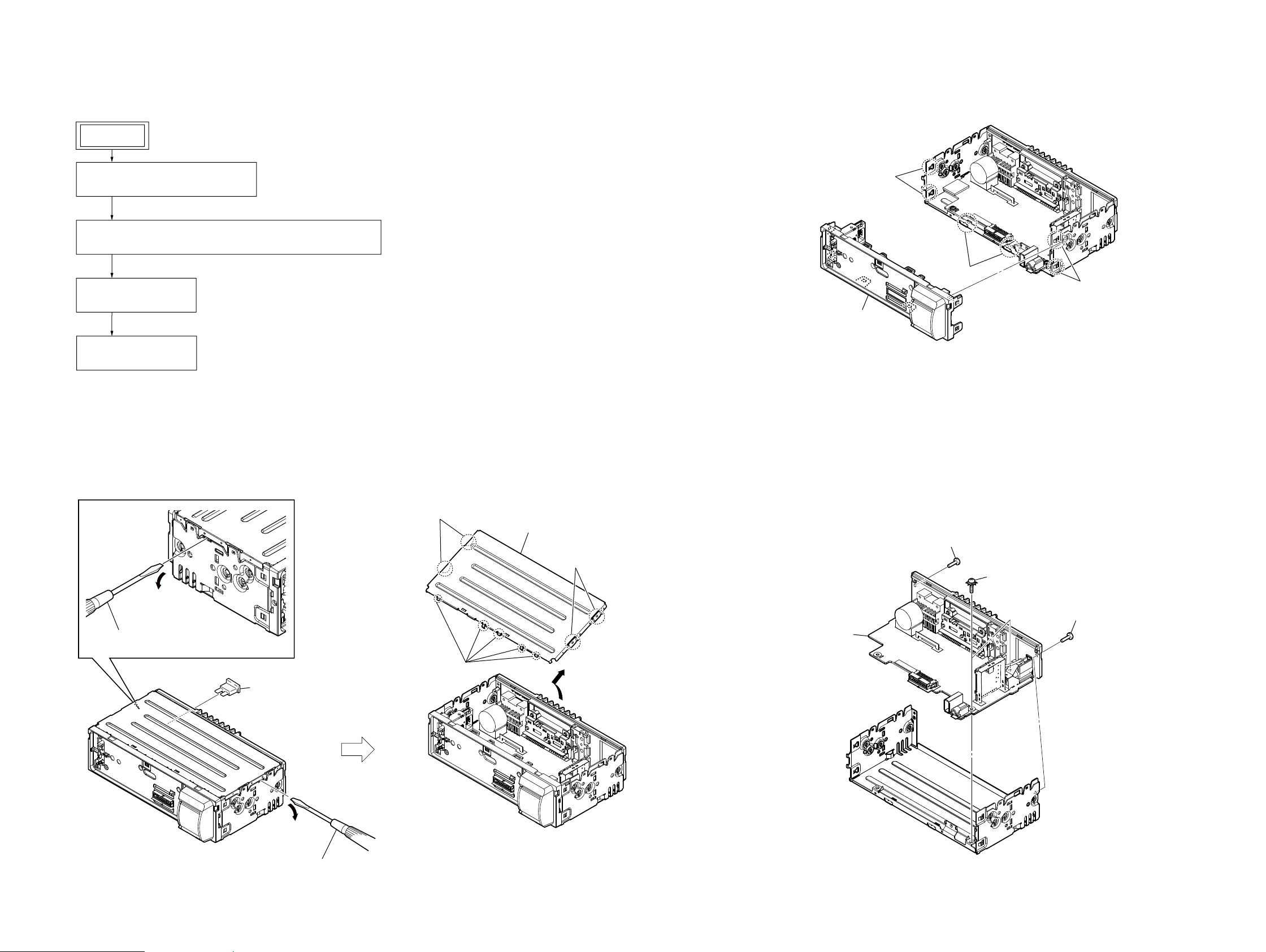
• This set can be disassembled in the order shown below.
3-1. DISASSEMBLY FLOW
SET
FRONT PANEL SECTION
Illustration of disassembly is omitted.
Note:
3-2. FUSE (BLADE TYPE) (AUTO FUSE) (10A/32V) (FU101), COVER
(Page 7)
3-3. SUB PANEL BLOCK
(Page 7)
3-4. MAIN BOARD
(Page 7)
3-3. SUB PANEL BLOCK
1 two claws
1 two claws
1 two claws
2 sub panel block
Note: Follow the disassembly procedure in the numerical order given.
3-2. FUSE (BLADE TYPE) (AUTO FUSE) (10A/32V) (FU101), COVER
3 two bosses
2 Insert a flathead screwdriver between the
cover and the chassis and raise the cover.
4 five claws
1 fuse (blade type) (auto fuse)
(10A/32V) (FU101)
5 cover
3 two bosses
3-4. MAIN BOARD
3 MAIN board
1 screw
(PTT2.6 u 8)
2 two ground point screws
(PTT2.6 u 6)
1 screw
(PTT2.6 u 8)
DSX-A30
2 Insert a flathead screwdriver between the
cover and the chassis and raise the cover.
77
DSX-A30
SECTION 4
DIAGRAMS
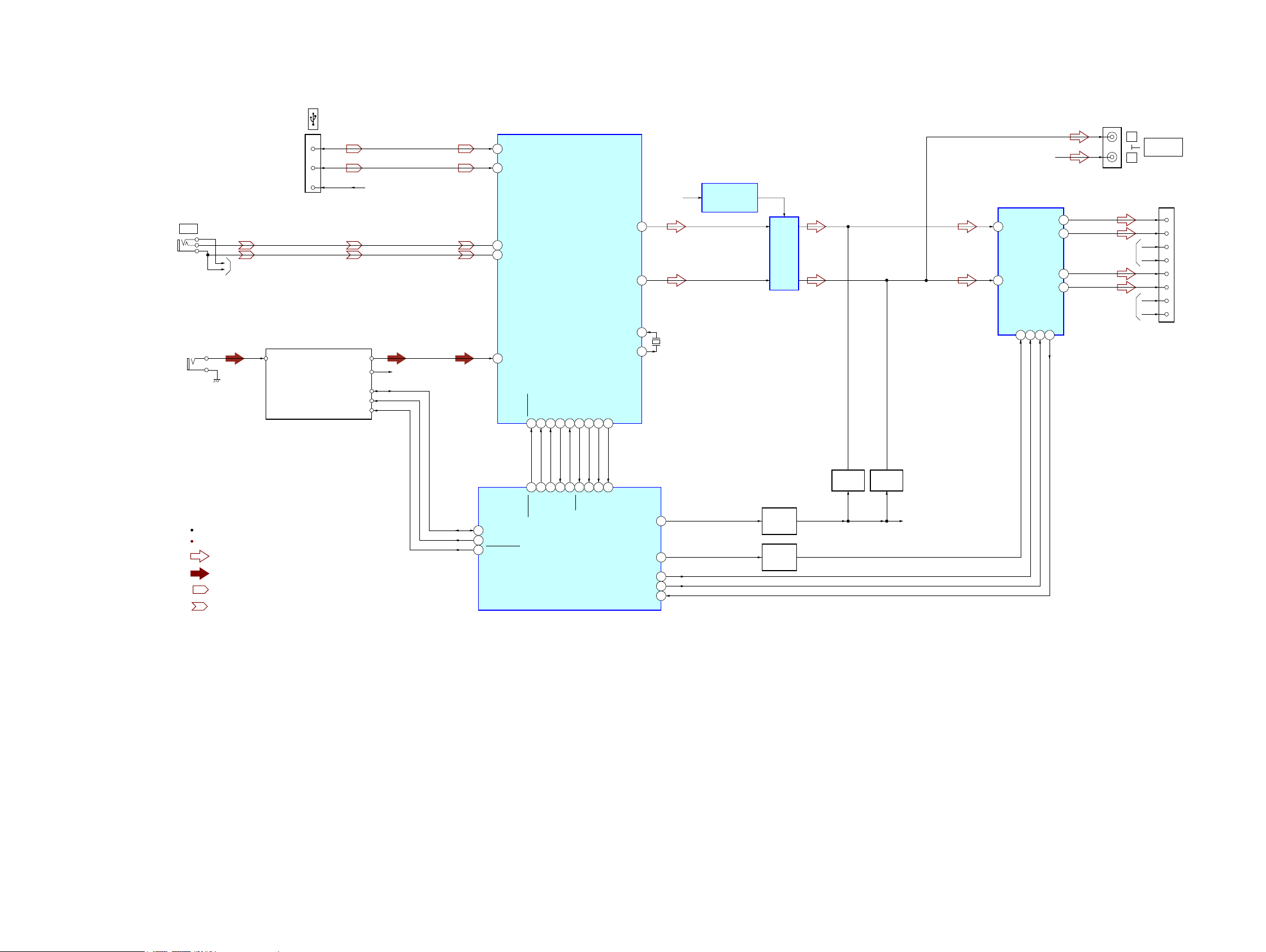
4-1. BLOCK DIAGRAM - MAIN Section -
CN201
3
D+
2
D–
1
J304
AUX
J303
(ANTENNA IN)
R-CH
VBUS
TUX-DSP02 (FM/AM TUNER UNIT)
RF_ANT_IN
TU251
AUDIO_OUT_L
AUDIO_OUT_R
USB_VBUS
R-CH
69
68
13
14
9
UDP1
UDM1
L3_IN_P
L3_IN_N
L1_IN
USB CONTROLLER,
INPUT SELECTOR,
AUDIO DSP,
ELECTRICAL VOLUME
IC201
LFOUT
LROUT
X12IN
X12OUT
J302
L
REAR
R-CH
R-CH
R
AUDIO OUT
CN102
1
9
4
12
2
10
3
11
FL+
FL–
FR+
FR–
RL+
RL–
RR+
RR–
R-CH
CENTER VOLTAGE
+8.5V
1
2
74
X201
12MHz
75
GENERATOR
IC303
LINE AMP
IC302
IN_FL
12
IN-RL
11
POWER AMP
IC304
MUTE22STBY4AC_GND16OFFSET
FL+
RL+
5
FL-
3
9
RL-
7
25
R-ch is omitted due to same as L-ch.
SIGNAL PATH
: AUDIO
: TUNER
: USB
: AUX
SDA
SCL
RSTN
45 HIT2_SDA
46 HIT2_SCL
47 HIT2_RESET
RESETB
SIFCK52SIFDI53SIFCE
SIFDO
51
18
55
54
21
22
19
20
SDI
SCK
SDO
SYSRST
SYSTEM CONTROLLER
IC101 (1/2)
CE
56
17
BUSYB
USB_IN
57
23
BUSY
USB_IN
WDT_MON
60
61
25
16
WDT_MON
CMD_ERR
CMD_ERR
AMP_MUTE
ATT
AMPSTB
BEEP
PIC_ERR
MUTING
Q305
MUTING
56
57
58
26
63
CONTROL
Q109, 110
MUTING
SWITCH
Q304
MUTING
Q303
R-CH
DSX-A30
88
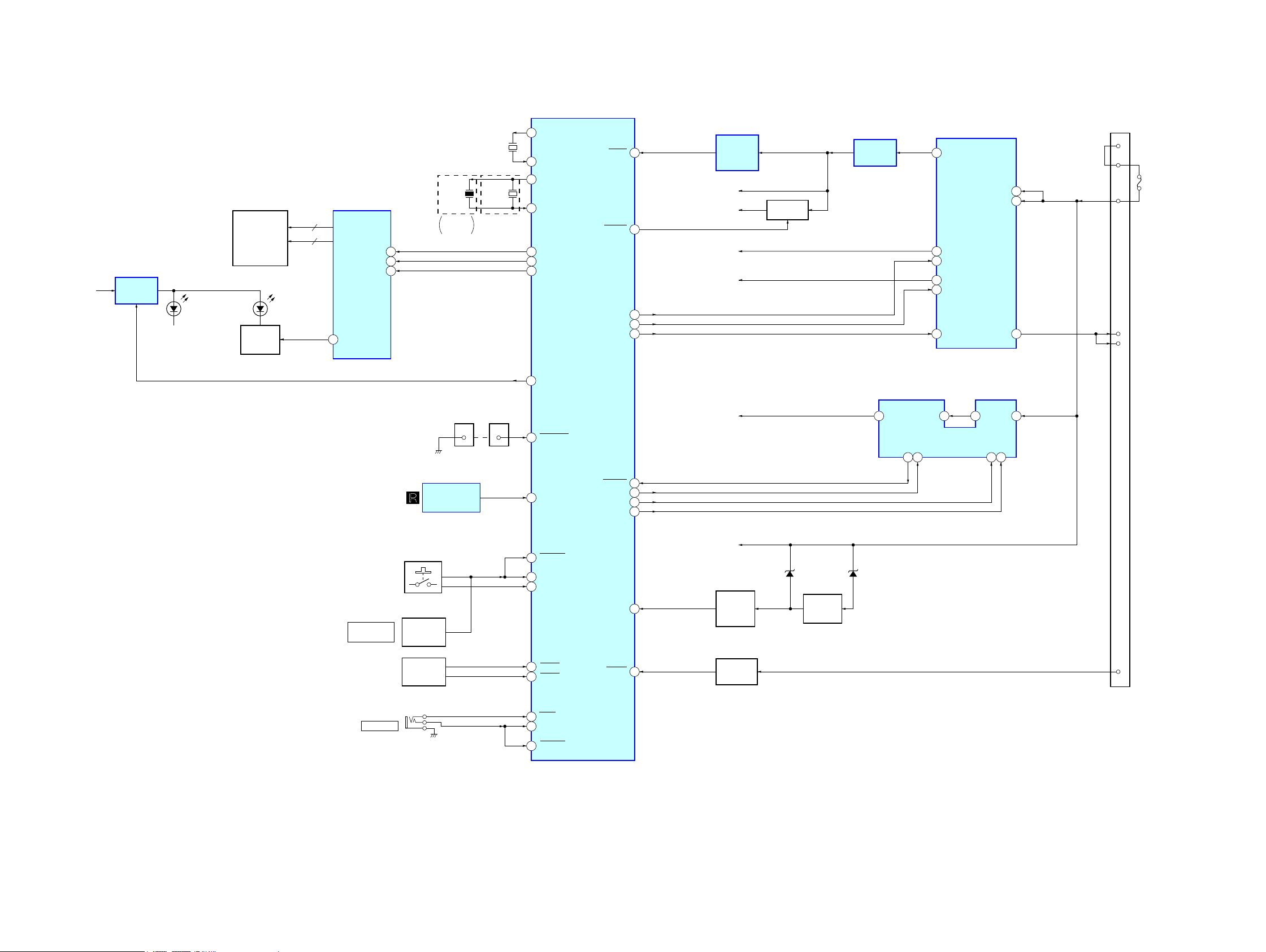
4-2. BLOCK DIAGRAM - DISPLAY/POWER SUPPLY Section -
B/U B+
+9V
REGULATOR
IC402
LED902 – 907,
LSW901 – 906 (1/2)
(ILLUMINATION)
LIQUID CRYSTAL DISPLAY
LCD901
SEG1 – SEG32
COM1 – COM4
(LCD BACK LIGHT)
DIMMER
CONTROL
Q901
LIQUID CRYSTAL DISPLAY DRIVER
32
4
LED901
2
IC901
SEG1 – SEG32
COM1 – COM4
DIMMER
48
DI
47
CL
46
CE
X102
7.92MHz
E, Mexican,
Indian
X101
32.768kHz
X102
7.92MHz
(Saudi Arabia)
9
8
11
13
99
100
98
XOUT
XIN
OSCOUT
OSCIN
LCD_SO
LCD_CLK
LCD_CE
SYSTEM CONTROLLER
IC101 (2/2)
RESET
SYS_ON
SYS_EN
AUDIO_EN
AMP_REM
DSX-A30
REGULATOR
VDD (BACKUP5V)
5
REG 3.3V
15
REG_EN
10
AUDIO 8.5V
3
AUDIO_EN
2
AMP_EN
12
IC401
VCC1
VCC2
AMP12V
9
8
13
RESET
10
87
73
74
72
GENERATOR
BU +3.3V
SYS_3.3V
VDD_3.3V
+8.5V
SIGNAL
IC105
B+ SWITCH
Q106
+3.3V
REGULATOR
IC102
CN102
16
18
19
5
6
+B
FU101
AMP-REM
ANT-REM
PUSH ENTER/
SELECT
(VOLUME)
REMOTE CONTROL
RECEIVER
LSW901 – 906 (2/2),
S901 – 906
(FRONT PANEL KEY)
ROTARY
ENCODER
S907 (1/2)
ROTARY
ENCODER
S907 (2/2)
CN001 CN103
IC902
ILL_ON
59
USB_VBUS
1212
1
90
93
92
79
80
NOSE_SW
SIRCS2
KEYACK1
KEYIN0
KEYIN1
RE_IN0
RE_IN1
FLT_USB
EN_USB
SYNC_OUT
EN_SYS
BU_IN
ACC_IN
50
48
24
51
B/U B+
D106
BACK UP
66
55
VOLTAGE
DETECT
Q101, 104
ACCESSORY
CHECK
Q106
BATTERY
CHECK
Q103
5 USBOUT
D107
DC/DC CONVERTER
EN_USB
FLT_USB
12
9
7
IC501
2LXUSBIN
3
VIN
SYNC8EN_SYS
4
ACC
7
DSX-A30
J101
REMOTE IN
88
95
89
RCIN1
RC_IN0
KEYACK0
99
DSX-A30
THIS NOTE IS COMMON FOR PRINTED WIRING BOARDS AND SCHEMATIC DIAGRAMS.
(In addition to this, the necessary note is printed in each block.)
For Printed Wiring Boards.
Note:
• X : Parts extracted from the component side.
• Y : Parts extracted from the conductor side.
• f : Internal component.
• : Pattern from the side which enables seeing.
(The other layers’ patterns are not indicated.)
Caution:
Pattern face side:
(Conductor Side)
Parts face side:
(Component Side)
• Indication of transistor.
C
Q
B
E
• Abbreviation
EA : Saudi Arabia model
IND : Indian model
MX : Mexican model
Note: When the MAIN board in this unit is replaced, the destination
setting is necessary. Refer to “NOTE THE MAIN BOARD OR
SYSTEM CONTROLLER (IC101) REPLACING” (page 4).
Parts on the pattern face side seen
from the pattern face are indicated.
Parts on the parts face side seen from
the parts face are indicated.
These are omitted.
For Schematic Diagrams.
Note:
• All capacitors are in μF unless otherwise noted. (p: pF)
50 WV or less are not indicated except for electrolytics
and tantalums.
• All resistors are in and 1/4 W or less unless otherwise
specifi ed.
• f : internal component.
• C : panel designation.
• A : B+ Line.
• Power voltages is dc 14.4V and fed with regulated dc
power supply from ACC and BATT cords.
• Voltages and waveforms are dc with respect to ground
under no-signal (detuned) conditions.
no mark
• Voltages are taken with a VOM (Input impedance 10 M).
Voltage variations may be noted due to normal production
• Waveforms are taken with a oscilloscope.
Voltage variations may be noted due to normal production
• Circled numbers refer to waveforms.
• Signal path.
F : AUDIO
f : TUNER
d : USB
E : AUX
• Abbreviation
EA : Saudi Arabia model
IND : Indian model
MX : Mexican model
: TUNER
tolerances.
tolerances.
Note: When the MAIN board in this unit is replaced, the destination
setting is necessary. Refer to “NOTE THE MAIN BOARD OR
SYSTEM CONTROLLER (IC101) REPLACING” (page 4).
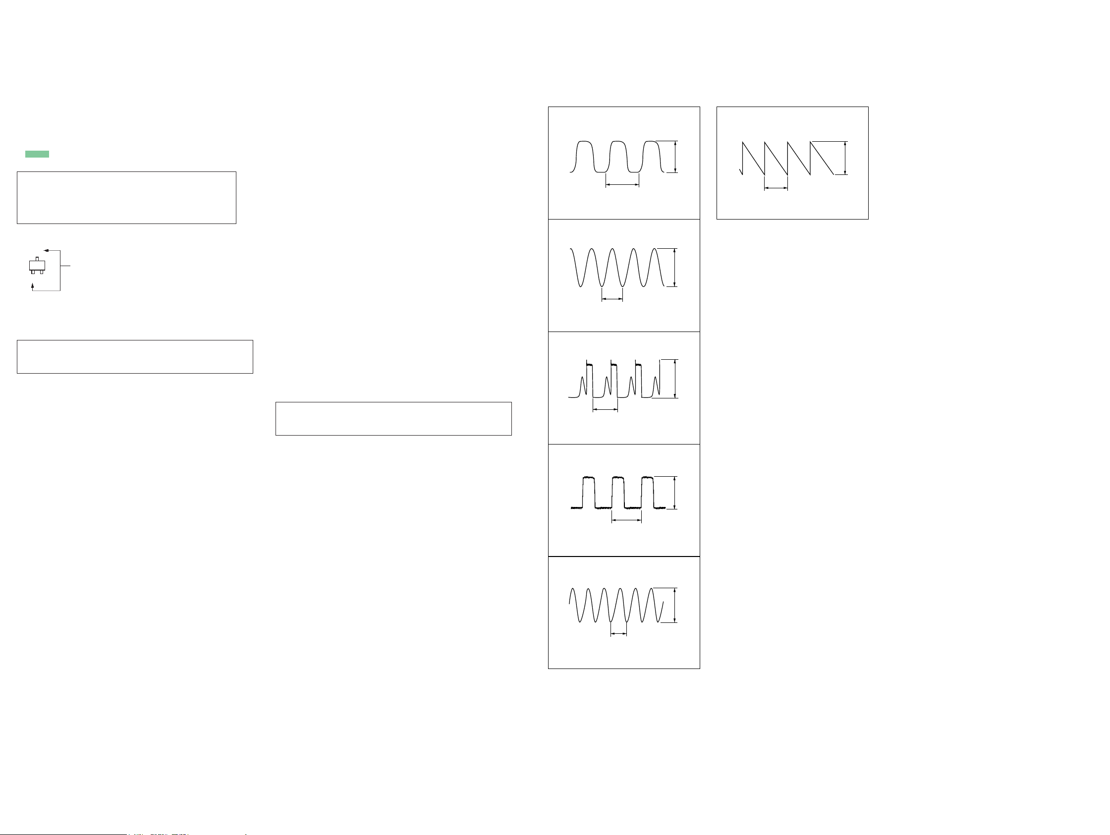
• Waveforms
– MAIN Board –
IC101 9 (XOUT)
1
1 V/DIV, 20 Ps/DIV
IC101 qa (OSCOUT)
2
126 ns
1 V/DIV, 50 ns/DIV
IC501 1 (BST), 2 (LX)
3
2.4 Ps
5 V/DIV, 1 Ps/DIV
30.5 Ps
2.5 Vp-p
3.5 Vp-p
18.2 Vp-p
– KEY Board –
IC901 rf (OSC)
qa
28.4 Ps
1 V/DIV, 10 Ps/DIV
2.6 Vp-p
IC501 8 (SYNC)
4
1 V/DIV, 1 Ps/DIV
IC201 ug (X12OUT)
5
1 V/DIV, 50 ns/DIV
2.4 Ps
3.3 Vp-p
3.2 Vp-p
83 ns
DSX-A30
1010
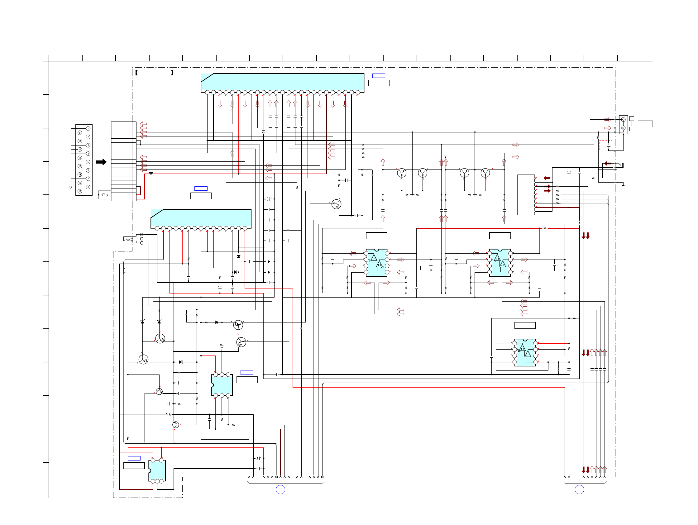
DSX-A30
4-3. SCHEMATIC DIAGRAM - MAIN Board (1/3) -
A
B
PW1
FRONT LCH+
FRONT LCH-
REAR LCH+
REAR LCH-
REAR RCH+
C
REAR RCH-
FRONT RCH+
FRONT RCH-
REM OUT
MAX 0.4A
D
ACC
GND
BATT
CN102
TO
FU101
10A
32V
E
J101
(REMOTE IN)
F
G
MAIN BOARD (1/3)
CN102
16P
1FL+
2RL+
3RR+
4FR+
5AMP-REM
6ANT-REM
7ACC
8GND
9FL–
10RL–
11RR–
12FR–
13TEL-ATT
L401
14ILL
140uH
15TEST
16+B
17+B
18+B
19+B
FB103
FB102
FB101
AUDIO_EN
SYS_EN
AMP_REM
NC2AUDIO_EN3AUDIO 8.5V4NC5VDD(BACKUP5V)6IKVDD7NC8VCC9VCC110REG_EN11IKREG12AMP_EN13AMP12V14GND15REG 3.3V
1
3.3
8.5
4.9
C403
10
• See page 20 for IC Block Diagrams.
5
TAB2PW_GND2(FL)3FL–4STBY5FL+6VCC27RL–8PW_GND1(RL)9RL+10RIPPLE11IN_RL12IN_FL13PRE_GND(BEEP?)14IN_FR15IN_RR16AC_GND17RR+18PW_GND3(RR)19RR–20VCC121FR+22MUTE23FR–24PW_GND4(FR)25OFFSET
1
7
7
7
2.4
14.1
IC B/D
IC401
REGULATOR
IC401
LV56831P-E
0
4.9
R403
10k
3.3
14.1
14.1
C411
220
16V
12
3.3
3.3
D405
GN1G
R404
10k
D404
C407
GN1G
10
C410
10
7
7
7
8.5
1
C3201C322
C319
22
16V
C401
3300
16V
C406
1
C412
0.22
C330
0.22
C318
0.22
D403
C408
GN1G
10
D401
GN1G
C404
1
9
101
13
142 1512
168
176113
184
IC B/D
IC304
POWER AMP
IC304
7
777
7
7
7
7
4.1
14.1
1
1
1
C324
C326
C328
1
1
1
1
C327
C3231C321
C325
C349
R356
C332
100
1
R337
0
Q304
DRC5114E0L
MUTING
SWITCH
R301
12k
R302
10k
220
4.1
C331
C301
220p
R305
4.7k
R304
100k
R334
10k
R336
150
C329
47p
LV47011P-E
3.3
J302
2P
L
REAR
AUDIO OUT
R
R339
R322
220
220R323
220R324
R325
220
R346
R338
4.7k
100
R326
220
C310
3
3
3
IC301
BA4560RFVM-TR
1
2
3
4
V-
LINE AMP
IC301
10
0.1
Q301
LTC614TUFP8T106
MUTING MUTING MUTING MUTING
0000
0000
8.4
8
V+
3
7
3
6
3
5
R307
100k
R327
10k
R306
4.7k
C302
0.1
Q302
LTC614TUFP8T106
R328
10k
C303
220p
R329
220
C313
10
R308
12k
R309
10k
R330
220
C314
R310
12k
R311
10k
10
Q303
LTC614TUFP8T106
C304
220p
R313
R312
100k
Q305
LTC614TUFP8T106
R331
R332
10k
10k
4.7k
3
3
3
IC302
BA4560RFVM-TR
1
2
3
4
V-
R333
220
C317
10
LINE AMP
IC302
TU251
TUX-DSP02
(TUNER UNIT)
0
RF_ANT_IN
1
RF_GND
2
POWER_GND
R315
100k
2
3
2
4
3.3
RSTN
5
2.6
SCL
6
2.4
SDA
7
8.4
+8.5V
8
9
R318
10
C308
220p
R314
4.7k
C305
10
AUDIO_OUT_L
AUDIO_OUT_R
8.4
8
V+
3
7
3
6
3
5
C255
C257
0.1
47
25V
R252
0
0R257
0R260
0R262
0R263
L251
4.7uH
R319
12k
R320
10k
0
C355
0.1
(EA)
J303
(ANTENNA IN)
R259
10
CAM251
HIT2_RST
HIT2_SCL
HIT2_SDA
(CHASSIS)
R106
R107
1k
D107
RKZ18B2KGP1
6.5
Q103
DRC5114E0L
BATTERY CHECK
3.3
Q106
2SC3052EF-T1-LEF
ACCESSORY CHECK
4.9 3.3
4
5
VIN
CONT2GND3NOISE
1
4.9
1k
0
0
C110
0.01
C106
1000
6.3V
BACK UP VOLTAGE DETECT
VOUT
RKZ18B2KGP1
R111
47k
C101
0.47
C102
0.47
R112
4.7k
0
ACC_IN
R405
5
100k
13.9
4
VSS
3.3
Q109
DRA5114E0L
13.9
Q109, 110
MUTING CONTROL
NC
+9V REGULATOR
S-1142B90I-E6T1U
R407
10k
0
DRC5114Y0L
IC B/D
IC402
IC402
R321
R335
47k
0
Q110
C306
10
C340
1
C122
100
16V
C119
1
1
3
2
5274
16
1
9
8
6
7
BOARD
MAIN
(2/3)
10
(Page 12)
111914
13
IC303
CENTER VOLTAGE GENERATOR
IC303
BA4560RFVM-TR
3
1
3
2
3
3
4
8
V+
7
6
5
V-
8.4
3
3
3
R317
12k
10
R316
10k
C231 1
C233 1
C237 1
24
23
221225
MAIN
BOARD
(3/3)
C239 1
26
(Page 13)
C309
10
18
2
R117
R114
10k
10k
D114
0.5
Q101, 104
R118
22
D116
DA2J10100L
C105
47
25V
14.1
6
VIN
VOUT2VSS3ON/OFF
R116
47k
1
8.9
C409
1
H
D106
RKZ7.5B2KGP1
I
6.5
0
Q101
DRC5144E0L
J
Q104
2SC4154TP-1EF
K
R105
220k
BUIN
L
IC B/D
IC102
+3.3V REGULATOR
IC102
M
MM1836A33NRE
DSX-A30
1111
 Loading...