

Page 1
DSR-PD150/PD150P
RMT-811
Ver 1.1 2000. 11
SERVICE MANUALSERVICE MANUAL
NTSC model : DSR-PD150
PAL model : DSR-PD150P
With SUPPLEMENT-1 (9-929-824-81)
Photo : DSR-PD150
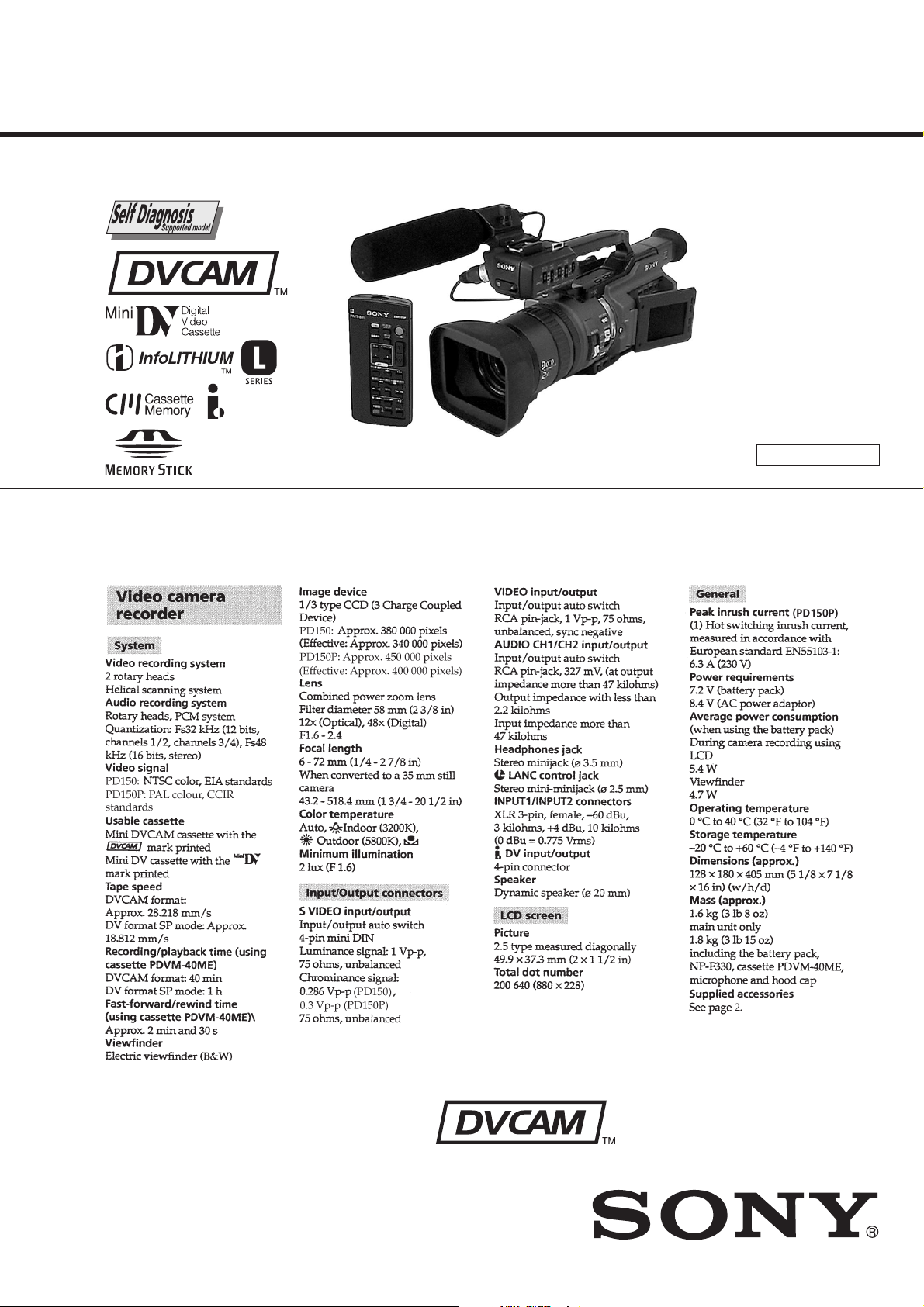
SPECIFICATIONS
US Model
Canadian Model
DSR-PD150
AEP Model
DSR-PD150P
C MECHANISM
— Continued on next page —
DIGITAL CAMCORDER
Page 2
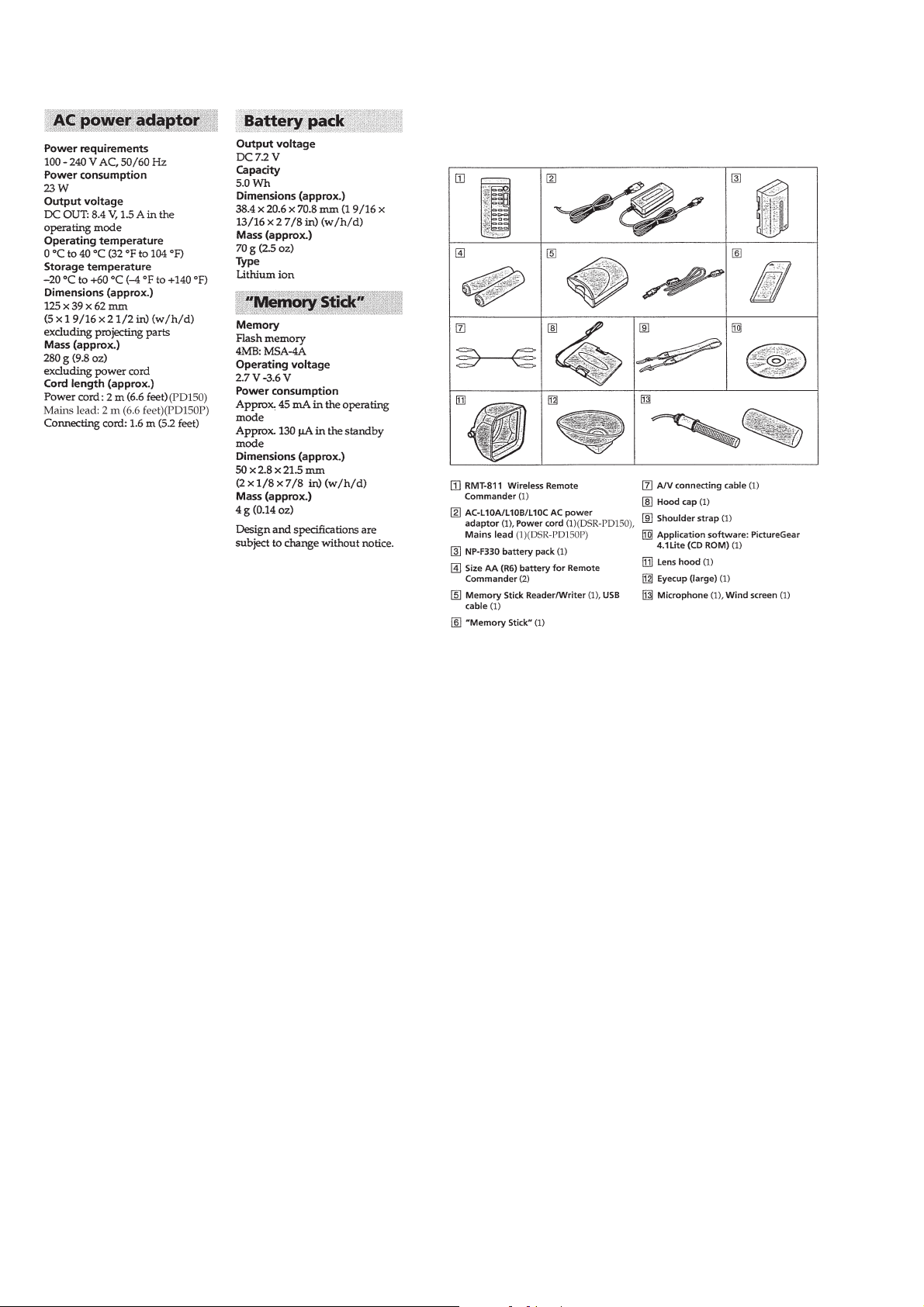
• SUPPLIED ACCESSORIES
Check that the following accessories are supplied with your
camcorder.
SAFETY-RELATED COMPONENT WARNING!!
COMPONENTS IDENTIFIED BY MARK 0 OR DOTTED LINE WITH
MARK 0 ON THE SCHEMATIC DIAGRAMS AND IN THE PARTS
LIST ARE CRITICAL TO SAFE OPERATION. REPLACE THESE
COMPONENTS WITH SONY PARTS WHOSE PART NUMBERS
APPEAR AS SHOWN IN THIS MANUAL OR IN SUPPLEMENTS
PUBLISHED BY SONY.
SAFETY CHECK-OUT
After correcting the original service problem, perform the following
safety checks before releasing the set to the customer.
1. Check the area of your repair for unsoldered or poorly-soldered
connections. Check the entire board surface for solder splashes
and bridges.
2. Check the interboard wiring to ensure that no wires are
"pinched" or contact high-wattage resistors.
3. Look for unauthorized replacement parts, particularly
transistors, that were installed during a previous repair . Point
them out to the customer and recommend their replacement.
ATTENTION AU COMPOSANT AYANT RAPPORT
À LA SÉCURITÉ!
LES COMPOSANTS IDENTIFÉS P AR UNE MARQUE 0 SUR LES
DIAGRAMMES SCHÉMA TIQUES ET LA LISTE DES PIÈCES SONT
CRITIQUES POUR LA SÉCURITÉ DE FONCTIONNEMENT. NE
REMPLACER CES COMPOSANTS QUE PAR DES PIÈSES SONY
DONT LES NUMÉROS SONT DONNÉS DANS CE MANUEL OU
DANS LES SUPPÉMENTS PUBLIÉS PAR SONY.
4. Look for parts which, through functioning, show obvious signs
of deterioration. Point them out to the customer and
recommend their replacement.
5. Check the B+ voltage to see it is at the values specified.
6. Flexible Circuit Board Repairing
• Keep the temperature of the soldering iron around 270˚C
during repairing.
• Do not touch the soldering iron on the same conductor of the
circuit board (within 3 times).
• Be careful not to apply force on the conductor when soldering
or unsoldering.
— 2 —
Page 3

TABLE OF CONTENTS
SERVICE NOTE
1. POWER SUPPLY DURING REPAIRS····························· 7
2. TO TAKE OUT A CASSETTE WHEN NOT EJECT
(FORCE EJECT) ································································ 7
SELF-DIAGNOSIS FUNCTION
1. SELF-DIAGNOSIS FUNCTION······································· 8
2. SELF-DIAGNOSIS DISPLAY ·········································· 8
3. SERVICE MODE DISPLAY ············································· 8
3-1. Display Method ··································································8
3-2. Switching of Backup No. ··················································· 8
3-3. End of Display···································································· 8
4. SELF-DIAGNOSIS CODE TABLE··································· 9
1. GENERAL
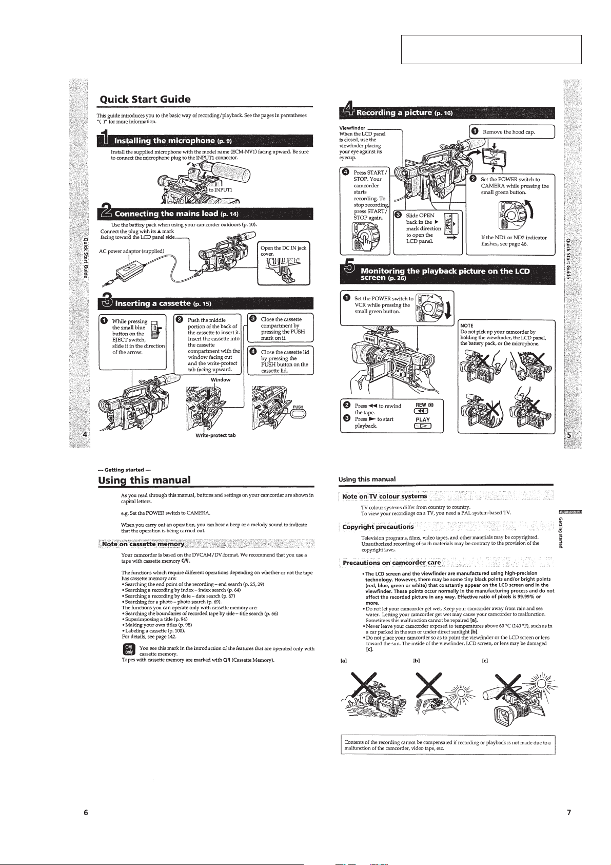
Quick Start Guide ······································································1-1
Getting started ···········································································1-1
Using this manual ··································································1-1
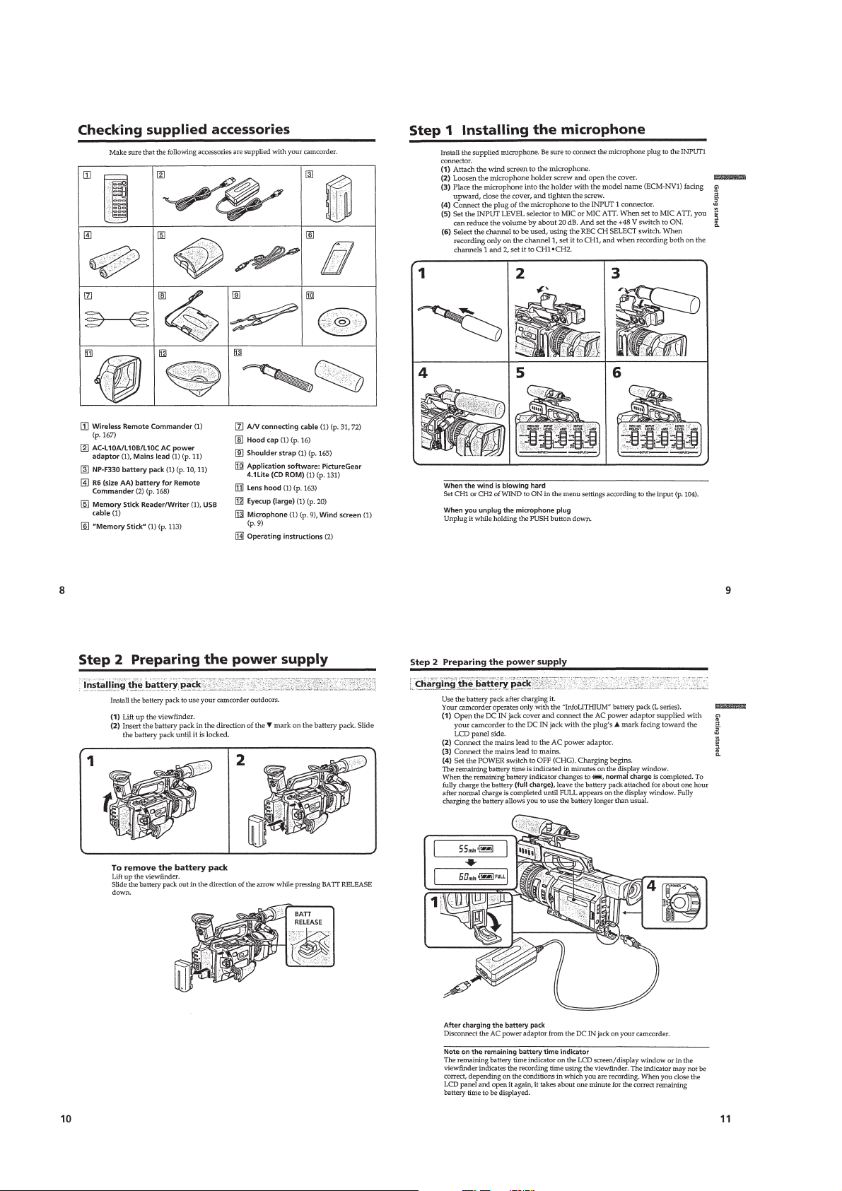
Checking supplied accessories ··············································1-2
Step 1 Inserting the microphone ············································1-2
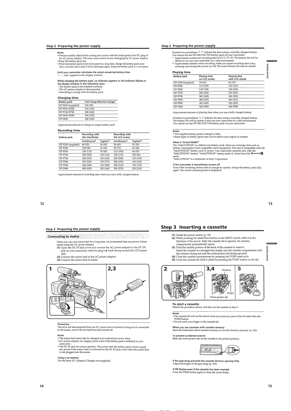
Step 2 Preparing the power supply ········································1-2
Step 3 Inserting a cassette······················································1-3
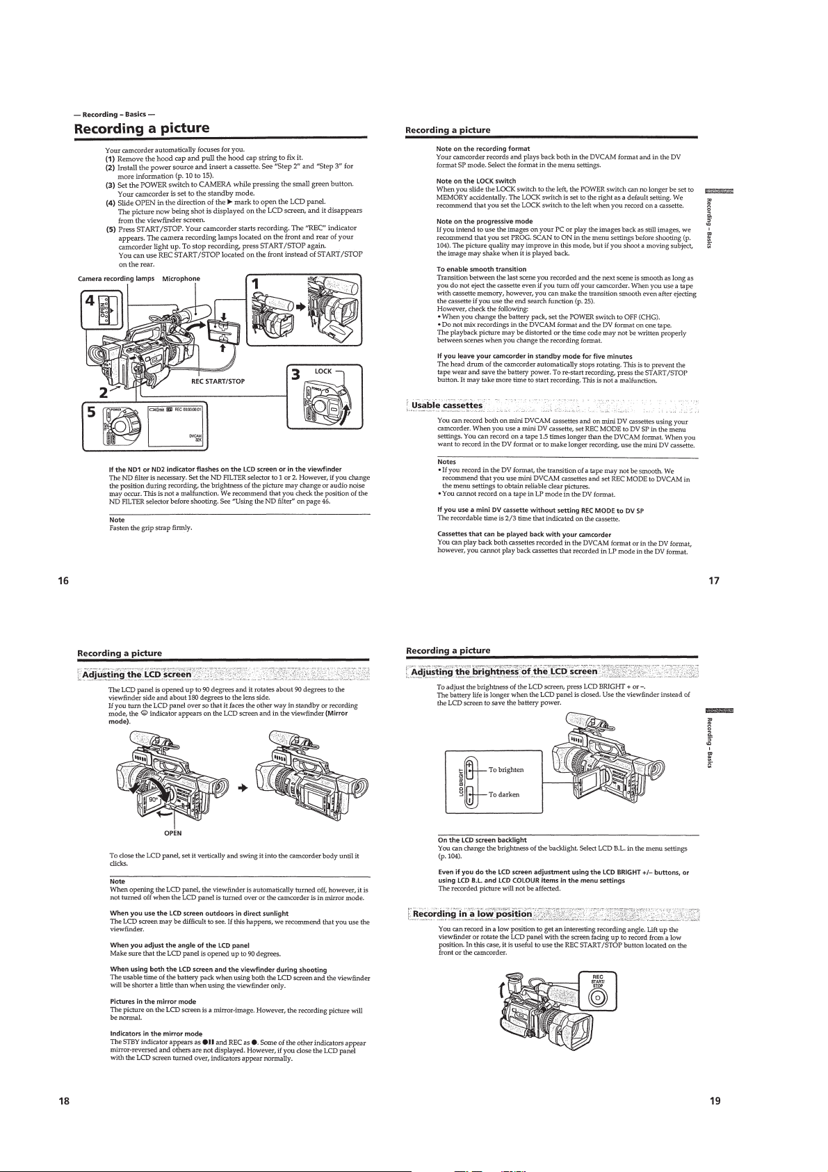
Recording –Basics ·····································································1-4
Recording a picture································································1-4
Shooting backlit subjects (BACK LIGHT)··························1-5
Spot light··············································································1-6
Checking the recording – END SEARCH/
EDIT SEARCH/Rec Review ···············································1-6
Playback –Basics ·······································································1-6
Playing back a tape ································································1-6
Viewing the recording on TV ················································1-7
Advanced Recording Operations···············································1-8
Recording a still image on a tape –Tape Photo recording ·····1-8
Shooting with all the pixels –PROG. SCAN ·························1-8
Using the guide frame····························································1-8
Using the wide mode ·····························································1-9
Using the fader function ························································1-9
Using special effects –Digital effect······································1-9
Shooting with manual adjustment ······································· 1-10
Adjusting the white balance·················································1-12
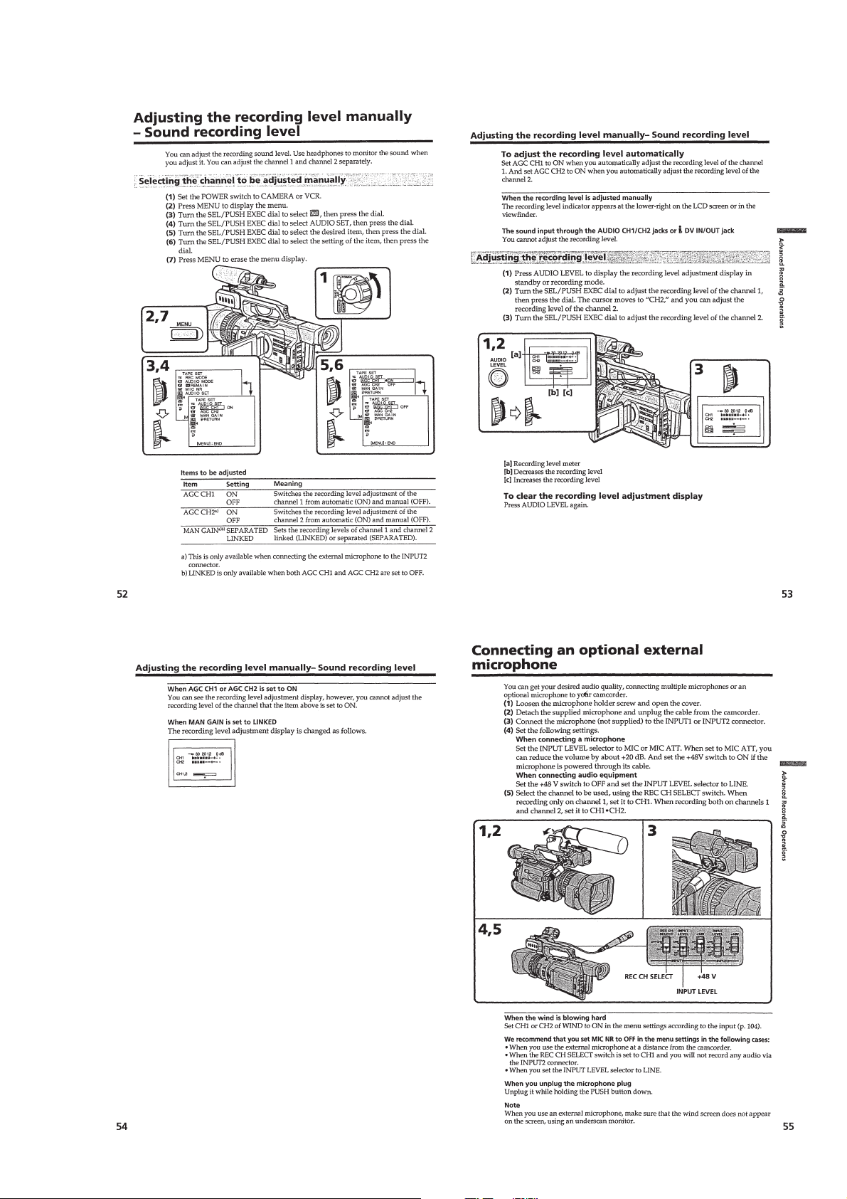
Adjusting recording level manually –Sound recording level ··
Connecting an optional external microphone ·························· 1-13
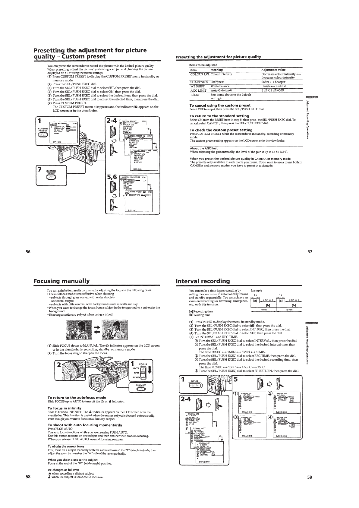
Presetting the adjustment for picture quality –Custom preset ··
Focusing manually·······························································1-14
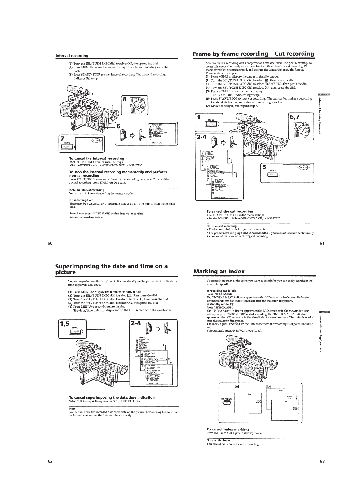
Interval recording·································································1-14
Frame by frame recording –Cut recording ··························1-15
Superimposing the date and time on a picture·····················1-15
Marking an Index·································································1-15
Advanced Playback Operations··············································· 1-16
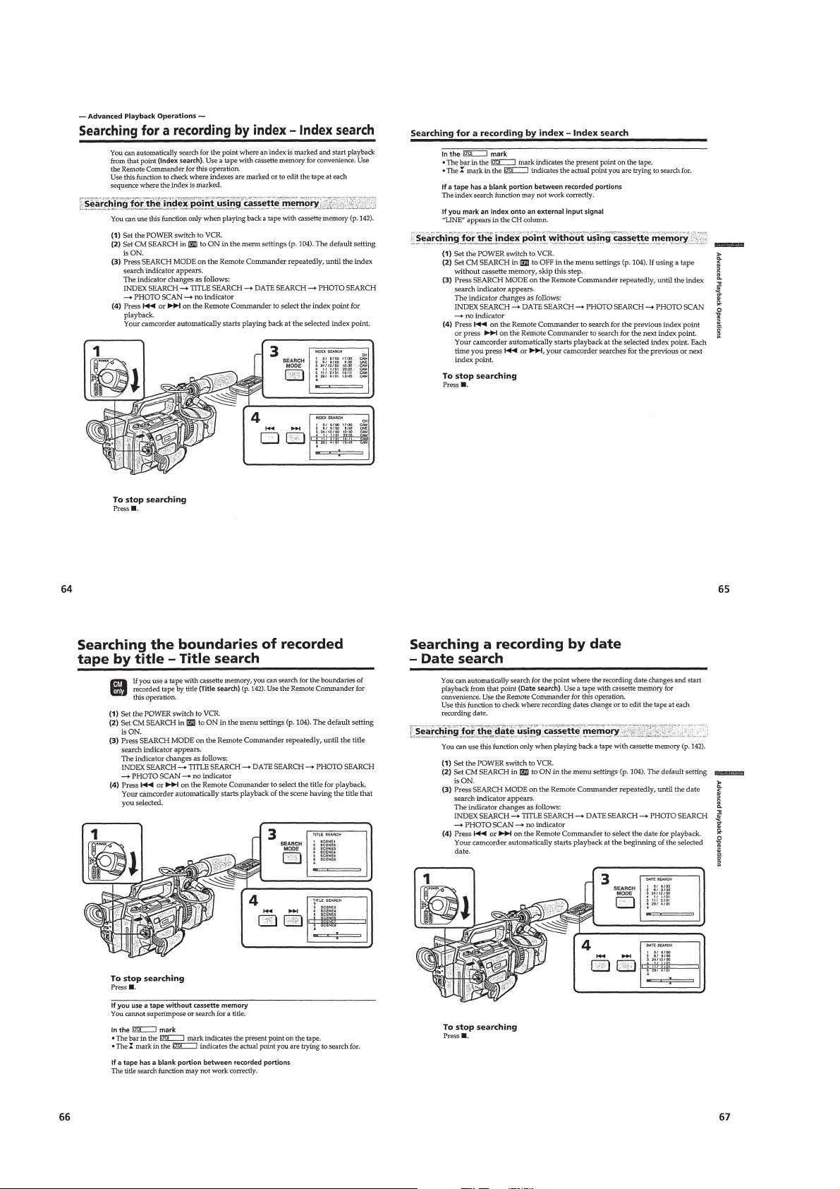
Searching for a recording by index –Index search ·············· 1-16
Searching the boundaries of recorded tape by title
–Title search·········································································1-16
Searching a recording by date –Date search························1-16
Searching for a photo –Photo search/Photo scan················· 1-17
Playing back a tape with digital effects ······························· 1-17
Editing ·····················································································1-18
Dubbing a tape ·····································································1-18
Dubbing only desired scenes –Digital program editing ·········1-18
Using with analog video unit and a PC
– Signal convert function·····················································1-20
Recording video or TV programs ········································1-20
Audio dubbing ·····································································1-21
Setting time values······························································· 1-22
Superimposing a title ··························································· 1-23
Making your own titles ························································1-24
Labeling a cassette ·······························································1-25
Erasing the cassette memory data········································1-25
1-13
1-14
Customizing Y our Camcorder ················································· 1-26
Changing the menu settings·················································1-26
Resetting the date and time··················································1-28
“Memory Stick” Operations ····················································1-28
Using a “Memory Stick” –introduction ·······························1-28
Recording still images on a “Memory Stick”
–Memory Photo recording ···················································1-29
Superimposing a still picture in a “Memory Stick”
on a moving picture –MEMORY MIX································1-30
Recording an image from a tape as a still image ·················1-31
Copying still images from a tape –Photo save·····················1-31
Viewing a still picture –Memory photo playback················ 1-32
Copying an image recorded on a “Memory Stick” to tapes ···1-33
Playing back images continuously –SLIDE SHOW···············
Preventing accidental erasure –Image protection ················1-33
Deleting images ···································································1-34
Writing a print mark –Print mark ········································1-34
Additional Information ····························································1-35
Compativility of DVCAM and DV formats ························1-35
Usable cassettes ···································································1-35
About i.LINK·······································································1-36
Troubleshooting ···································································1-36
Self-diagnosis display ··························································1-37
Warning indicators and messages ········································1-38
Using your camcorder abroad·············································· 1-38
Maintenance information and precautions···························1-38
Quick Reference ······································································1-40
Identifying the parts and controls ········································1-40
Quick Function Guide ·························································1-42
Auto Logo Insert for Copyright Protection ·····························1-43
Introduction –Auto Logo Insert ···········································1-43
Preparing a logo file·····························································1-43
Registering your password ··················································1-43
Registering a still image to be used as a logo ······················1-44
Deactivating the auto logo insert function···························1-44
Changing or resetting the setup ···········································1-45
Precautions concerning the auto logo insert function··········1-45
1-33
2. DISASSEMBLY
2-1. LCD SECTION (HL-011, PD-126 BOARDS,
INVERTER TRANSFORMER UNIT) ···························2-2
2-2. EVF SECTION (LB-065D BOARD)······························2-3
2-3. UPPER HANDLE BLOCK ASSEMBLY ·······················2-4
2-4. FK-076, MA-386D BOARDS·········································2-4
2-5. XD-001, XS-001, XM-001 BOARDS·····························2-5
2-6. CABINET (L) BLOCK ASSEMBLY, MECHANISM
DECK, VC-242D, DD-138D, JK-190 BOARDS
(FOR FORCE EJECT OF CASSETTE AND VTR
SECTION CHECK) ························································2-6
2-7. CABINET (R) BLOCK ASSEMBLY ·····························2-8
2-8. CABINET BOTTOM (D) ASSEMBLY··························2-8
2-9. BATTERY PANEL BLOCK ASSEMBLY
(MK-014, KP-010, MS-049 BOARDS)··························2-9
2-10. EVF BLOCK ASSEMBLY ·············································2-9
2-11. LA-026, DD-138D, VC-242D, JK-190 BOARDS,
MECHANISM DECK···················································2-10
2-12. LENS BLOCK ASSEMBLY, CENTER FRAME
ASSEMBLY ··································································2-11
2-13. CD-254, SE-108 BOARDS, ZOOM LENS
ASSEMBLY ··································································2-12
2-14. CONTROL SWITCH BLOCK (PS-4980),
CONTROL SWITCH BLOCK (CF-4980) ···················2-12
2-15. CK-093 BOARD ···························································2-13
2-16. CONTROL SWITCH BLOCK (ED-4980),
HINGE ASSEMBL Y·····················································2-14
2-17. CIRCUIT BOARDS LOCATION ·································2-15
2-18. FLEXIBLE BOARDS LOCATION ······························2-16
— 3 —
Page 4

3. BLOCK DIAGRAMS
3-1. OVERALL BLOCK DIAGRAM (1/4) ···························3-1
3-2. OVERALL BLOCK DIAGRAM (2/4) ···························3-3
3-3. OVERALL BLOCK DIAGRAM (3/4) ···························3-5
3-4. OVERALL BLOCK DIAGRAM (4/4) ···························3-7
3-5. POWER BLOCK DIAGRAM (1/3) ································3-9
3-6. POWER BLOCK DIAGRAM (2/3) ······························3-11
3-7. POWER BLOCK DIAGRAM (3/3) ······························3-13
4. PRINTED WIRING BOARDS AND
SCHEMATIC DIAGRAMS
4-1. FRAME SCHEMATIC DIAGRAM (1/3) ·······················4-1
FRAME SCHEMATIC DIAGRAM (2/3) ·······················4-3
FRAME SCHEMATIC DIAGRAM (3/3) ·······················4-5
4-2. PRINTED WIRING BOARDS AND
SCHEMATIC DIAGRAMS ············································4-8
• CD-254 (CCD IMAGER)
SCHEMATIC DIAGRAM ······························ 4-9
• CD-254 (CCD IMAGER)
PRINTED WIRING BOARD ·······················4-11
• VC-242D (S/H AGC, TG)(1/18)
SCHEMATIC DIAGRAM ···························· 4-13
• VC-242D (CAMERA SIGNAL PROCESS)(2/18)
SCHEMATIC DIAGRAM ···························· 4-15
• VC-242D (MS I/F)(3/18)
SCHEMATIC DIAGRAM ···························· 4-17
• VC-242D (RS 232C I/F, STILL CONTROL)(4/18)
SCHEMATIC DIAGRAM ···························· 4-19
• VC-242D (MS DRIVE)(5/18)
SCHEMATIC DIAGRAM ···························· 4-21
• VC-242D (DV SIGNAL PROCESS)(6/18)
SCHEMATIC DIAGRAM ···························· 4-23
• VC-242D (DV INTERFACE)(7/18)
SCHEMATIC DIAGRAM ···························· 4-25
• VC-242D (REC/PB AMP)(8/18)
SCHEMATIC DIAGRAM ···························· 4-27
• VC-242D (LINE IN/OUT)(9/18)
SCHEMATIC DIAGRAM ···························· 4-29
• VC-242D (LINE A/D)(10/18)
SCHEMATIC DIAGRAM ···························· 4-31
• VC-242D (RGB DRIVE/TG)(11/18)
SCHEMATIC DIAGRAM ···························· 4-33
• VC-242D (CAMERA CONTROL)(12/18)
SCHEMATIC DIAGRAM ···························· 4-35
• VC-242D (MECHANISM CONTROL)(13/18)
SCHEMATIC DIAGRAM ···························· 4-37
• VC-242D (DRUM/CAPSTAN MOTOR DRIVE)(14/18)
SCHEMATIC DIAGRAM ···························· 4-39
• FP-594 (LOADING MOTOR, S/T REEL SENSOR)
PRINTED WIRING BOARD ·······················4-41
• VC-242D (HI CONTROL)(15/18)
SCHEMATIC DIAGRAM ···························· 4-43
• VC-242D (AU LINE A/D, D/A)(16/18)
SCHEMATIC DIAGRAM ···························· 4-45
• VC-242D (LINE AMP)(17/18)
SCHEMATIC DIAGRAM ···························· 4-47
• VC-242D (CONNECTOR)(18/18)
SCHEMATIC DIAGRAM ···························· 4-49
• VC-242D (S/H AGC, TG, CAMERA SIGNAL
PROCESS, MS I/F, RS232C I/F, STILL CONTROL,
MS DRIVE, DV SIGNAL PROCESS, REC/PB AMP,
LINE IN/OUT, LINE A/D, RGB DRIVE/TG,
CAMERA CONTROL, MECHANISM CONTROL,
DRUM/CAPSTAN MOTOR DRIVE, HI CONTROL,
AU LINE A/D, D/A, LINE AMP)
PRINTED WIRING BOARD ·······················4-51
• JK-190 (JACK BOARD)
PRINTED WIRING BOARD ·······················4-55
• JK-190 (JACK BOARD)
SCHEMATIC DIAGRAM ···························· 4-57
• CK-093 (KEY IN)
PRINTED WIRING BOARD ·······················4-59
• CK-093 (KEY IN)
SCHEMATIC DIAGRAM ···························· 4-61
• PD-126 (RGB DRIVE/TG)
PRINTED WIRING BOARD ·······················4-63
• PD-126 (RGB DRIVE/TG)
SCHEMATIC DIAGRAM ···························· 4-65
• LA-026 (ZOOM/FOCUS DRIVE, VAP DRIVE,
KEY IN/CONNECTOR)
PRINTED WIRING BOARD ·······················4-67
• LA-026 (ZOOM/FOCUS DRIVE)(1/3)
SCHEMATIC DIAGRAM ···························· 4-69
• LA-026 (VAP DRIVE)(2/3)
SCHEMATIC DIAGRAM ···························· 4-71
• LA-026 (KEY IN/CONNECTOR)(3/3)
SCHEMATIC DIAGRAM ···························· 4-73
• SE-108 (VAP SENSOR)
PRINTED WIRING BOARD ·······················4-75
• MS-049 (MS CONNECTOR)
PRINTED WIRING BOARD ·······················4-77
• KP-010 (SELECT DIAL)
PRINTED WIRING BOARD ·······················4-79
• MK-014 (CONTROL KEY)
PRINTED WIRING BOARD ·······················4-79
• KP-010 (LCD DRIVE), MK-014 (CONTROL KEY),
MS-049 (MS CONNECTOR)
SCHEMATIC DIAGRAM ···························· 4-81
• FK-076 (CONTROL SWITCH)
PRINTED WIRING BOARD ·······················4-83
• FK-076 (CONTROL SWITCH)
SCHEMATIC DIAGRAM ···························· 4-85
• XD-001 (DC/DC CONVERTER SIRCS),
XS-001 (MIC SELECT)
PRINTED WIRING BOARDS ·····················4-87
• XD-001 (DC/DC CONVERTER SIRCS),
XS-001 (MIC SELECT)
SCHEMATIC DIAGRAM ···························· 4-89
• XM-001 (MIC AMP)
PRINTED WIRING BOARD ·······················4-91
• XM-001 (MIC AMP)
SCHEMATIC DIAGRAM ···························· 4-93
• LB-065D (BACK LIGHT)
PRINTED WIRING BOARD ·······················4-96
• LB-065D (BACK LIGHT)
SCHEMATIC DIAGRAM ···························· 4-97
• HL-011 (LCD DRIVE)
PRINTED WIRING BOARD ·······················4-99
• HL-011 (LCD DRIVE)
SCHEMATIC DIAGRAM ·························· 4-101
• MA-386D (AUDIO AMP)
PRINTED WIRING BOARD ·····················4-103
• MA-386D (AUDIO AMP)
SCHEMATIC DIAGRAM ·························· 4-105
• DD-138D (DC/DC CONVERTER, DC REGURATOR)
PRINTED WIRING BOARD ·····················4-107
• DD-138D (DC/DC CONVERTER)(1/2)
SCHEMATIC DIAGRAM ·························· 4-109
• DD-138D (DC REGURATOR)(2/2)
SCHEMATIC DIAGRAM ·························· 4-111
4-3. WAVEFORMS ····························································4-113
4-4. MOUNTED PARTS LOCATION ·······························4-118
— 4 —
Page 5

5 ADJUSTMENTS
1. Before starting adjustment···············································5-1
1-1. Adjusting items when replacing main parts and boards.·5-2
5-1. CAMERA SECTION ADJUSTMENT···························5-4
1-1. PREPARATIONS BEFORE ADJUSTMENT
(CAMERA SECTION) ···················································5-4
1-1-1.List of Service Tools························································5-4
1-1-2.Preparations ····································································· 5-6
1-1-3.Precaution ········································································5-8
1. Setting the Switch···························································· 5-8
2. Order of Adjustments ······················································5-8
3. Subjects ···········································································5-8
1-2. INITIALIZATION OF A, B, C, D, E, F, 8 PAGE DATA···5-9
1-2-1.INITIALIZATION OF A, C, D, 8 PAGE DATA ·············5-9
1. Initializing the C, D, 8 Page Data····································5-9
2. Modification of C, D, 8 Page Data ··································5-9
3. C Page Table ····································································5-9
4. D Page Table ··································································5-11
5. 8 Page Table···································································5-12
6. Initializing the A Page Data··········································· 5-12
1-2-2.INITIALIZATION OF B PAGE DATA ·························5-13
1. Initializing the B Page Data···········································5-13
2. Modification of B Page Data·········································5-13
3. B Page Table ··································································5-13
1-2-3.INITIALIZATION OF E, F PAGE DATA·····················5-14
1. Initializing the E, F Page Data·······································5-14
2. Modification of E, F Page Data ·····································5-14
3. Modification of E Page Data ········································· 5-14
4. F Page Table ··································································5-15
5. E Page Table ·································································· 5-16
1-3. CAMERA SYSTEM ADJUSTMENTS························ 5-17
1. 27MHz Origin Oscillation Adjustment
(VC-242D board) ··························································5-17
2. Zoom Key Center Adjustment ·······································5-17
3. HALL Adjustment ·························································5-18
4. Offset Adjustment··························································5-18
5. Flange Back Adjustment (Using Minipattern Box)·······5-19
6. Flange Back Adjustment
(Using Flange Back Adjustment Chart and Subject
More Than 500m Away) ··············································· 5-20
6-1. Flange Back Adjustment (1)··········································5-20
6-2. Flange Back Adjustment (2)··········································5-20
7. Flange Back Check························································ 5-21
8. Picture Frame Setting ····················································5-21
9. Pre White Balance Data Input ·······································5-22
10. Auto White Balance Standard Data Input ·····················5-22
11. MAX GAIN Adjustment ···············································5-23
12. LV Standard Da ta Input·················································5-23
13. White Balance ND Filter 1 Compensation ····················5-24
14. White Balance ND Filter 2 Compensation ····················5-24
15. Auto White Balance Adjustment ··································· 5-25
16. Color Reproduction Adjustment (ND Filter OFF) ········5-25
17. Color Reproduction Adjustment (ND Filter 1)··············5-26
18. Color Reproduction Adjustment (ND Filter 2)··············5-26
19. White Balance Check ····················································5-27
20. Steady Shot Adjustment ················································5-28
20-1. Steady Shot Adjustment (1)···········································5-29
20-2. Steady Shot Adjustment (2)···········································5-30
1-4. ELECTRONIC VIEWFINDER SYSTEM
ADJUSTMENT·····························································5-31
1. VCO Adjustment (VC-242D board)······························ 5-31
2. Bright Adjustment (1) (VC-242D board) ······················5-32
3. Bright Adjustment (2) (VC-242D board) ······················5-32
4. Contrast Adjustment (VC-242D board) ························5-33
5. Backlight Consumption Current Adjustment
(VC-242D board) ··························································5-33
1-5. LCD SYSTEM ADJUSTMENT ···································5-34
1. VCO Adjustment (PD-126 board)································· 5-34
2. Bright Adjustment (PD-126 board) ·······························5-35
3. Black Limit Adjustment (PD-126 board) ······················5-35
4. Contrast Adjustment (PD-126 board)····························5-36
5. Center Level Adjustment (PD-126 board)····················· 5-36
6. V-COM Adjustment (PD-126 board) ····························5-37
7. White Balance Adjustment (PD-126 board)··················5-37
5-2. MECHANICAL SECTION ADJUSTMENT ···············5-38
2-1. PARTS REPLACEMENT AND PREPARATION
FOR ADJUSTMENT ····················································5-38
2-1-1.Outline ···········································································5-38
1. Manual test ····································································5-38
2. Step test ········································································· 5-38
3. Auto test ········································································5-38
2-1-2.Mechanism Condition (Position) Shifting Order List ···5-38
2-1-3.Mode Selector II (A-6082-282-A) Connection ·············5-38
2-1-4.The Mechanical Adjustment Requires the Following
Tools ··············································································5-39
2-2. P ARTS REPLACEMENT ·············································5-40
2-2-1.Tape Fall Stopper, HC Roller and HC Arm ···················5-40
2-2-2.Drum Assembly and Drum Base Block Assembly········5-40
2-2-3.Damper Assembly, Cassette Compartment Assembly
and Extension Spring·····················································5-41
2-2-4.Reel Table (S) / Reel Table (T) Assembly ····················· 5-42
2-2-5.Cassette Base Block Assembly, Gooseneck Gear
Assembly and Relay Gear ·············································5-42
2-2-6.TG1 Adjustment Plate Assembly, Tension Coil Spring
(TG1), TG1 Arm Assembly, TG7 Retainer Spring and
TG7 Arm Block Assembly ············································5-43
2-2-7.Brake Slider Assembly, Pinch Slider Assembly and
Cam Gear·······································································5-43
2-2-8.Pinch Arm Assembly, Torsion Spring (TG7LD), Pinch
Press Arm and Eject Arm ··············································5-44
2-2-9.GL Block Assembly, GL Driving Gear and HC Driving
Arm················································································5-44
2-2-10. Capstan Motor, Conversion Pulley, Timing Belt and
Holder ··········································································5-45
2-2-11. L Motor Block Assembly and FP-594 Flexible Board ·· 5-46
2-2-12. Reset Arm (S), Brake (S), Brake Rack (S), Brake (T),
Brake Gear (T), Brake Spring (T) and
Extension Spring ·························································5-47
2-2-13. Coaster (S) / (T) Assembly, GL Arm (S) / (T) Assembly,
Guide Rail, GL Gear (S) / (T) and Torsion Spring
(GLS) / (GLT) ······························································5-48
2-2-14. L Motor Assembly, Motor Shield, FP-248 Flexible Board,
TG1 Spring Hook, Spring Hook Fulcrum Base,
Spring Hook Driving Arm, Worm Shaft, Deceleration
Gear and Motor Holder ···············································5-49
2-3. CHECK AND ADJUSTMENT ·····································5-50
2-3-1.FWD Position Checking and Adjustment ····················· 5-51
2-3-2.FWD Back Tension Checking and Adjustment ·············5-51
2-2-3.Reel Table (S) / Reel Table (T) Torque Check ··············5-52
2-3-4.Preparation for Tape Path Checking and Adjustment····5-53
2-3-5.Track Checking and Adjustment ···································5-54
2-3-6.TG7 Slack Checking and Adjustment ···························5-54
2-3-7.Curl Checking and Adjustment ·····································5-55
2-3-8.CUE / REV Check·························································5-55
2-3-9.Rising Check ·································································5-55
2-4. PERIODIC CHECK ······················································5-56
2-4-1.Cleaning of Rotary Drum Assembly ·····························5-56
2-4-2.Cleaning of Tape Path System·······································5-56
2-4-3.Periodic Checks ·····························································5-56
5-3. VIDEO SECTION ADJUSTMENTS ···························5-57
3-1. PREPARATIONS BEFORE ADJUSTMENTS ············5-57
3-1-1.Equipment Required ······················································5-57
— 5 —
Page 6

3-1-2.Precautions on Adjusting···············································5-58
3-1-3.HOW TO ENTER RECORD MODE WITHOUT
CASSETTE ···································································5-58
3-1-4.HOW TO ENTER PLAYBACK MODE WITHOUT
CASSETTE ···································································5-58
3-1-5.Adjusting Connectors ···················································· 5-59
3-1-6.Connecting the Equipment ············································5-59
3-1-7.Alignment Tapes····························································5-60
3-1-8.Input/Output Level and Impedance ·······························5-60
3-2. SYSTEM CONTROL SYSTEM ADJUSTMENT ········5-61
1. Initialization of A, B, C, D, E, F, 8 Page Data···············5-61
2. Serial No. Input ·····························································5-61
2-1. Company ID Input·························································5-61
2-2. Serial No. Input ·····························································5-61
3. Battery End Adjustment ················································5-63
3-3. SERVO AND RF SYSTEM ADJUSTMENT ···············5-64
1. Cap FG Duty Adjustment (VC-242D board) ················5-64
2. T reel FG Duty Adjustment (VC-242D board) ·············5-64
3. PLL f0 & LPF f0 Adjustment (VC-242D board)············ 5-64
4. Switching Position Adjustment (VC-242D board)········5-65
5. AGC Center Level and APC & AEQ Adjustment ·········5-65
5-1. Preparations before adjustments····································5-65
5-2. AGC Center Level Adjustment (VC-242D board) ········5-65
5-3. APC & AEQ Adjustment (VC-242D Board) ················5-66
5-4. Processing after Completing Adjustments ····················5-66
6. PLL f0 & LPF f0 Final Adjustment (VC-242D board)···5-66
3-4. VIDEO SYSTEM ADJUSTMENTS·····························5-67
3-4-1.Base Band Block Adjustments ······································5-67
1. Chroma BPF f0 Adjustment (VC-242D board) ·············5-67
2. S VIDEO OUT Y Level Adjustment (VC-242D board) ·· 5-67
3. S VIDEO OUT Chroma Level Adjustment
(VC-242D board) ··························································5-68
VIDEO OUT Y , Chroma Level Check (VC-242D board)··
4.
3-4-2. BIST Check ··································································5-69
1. Playback System Check ················································5-69
1-1. Preparations for Playback··············································5-69
1-2. IC301 TRX (RF) PB BIST Check·································5-69
1-3. IC301 AUD (ABUS) PB BIST Check ···························5-69
1-4. IC301 VFD PB BIST Check ·········································5-69
1-5. IC301 ENCODER BIST Check ····································5-70
1-6. Processing after Completing Playback System Check··5-70
3-5. AUDIO SYSTEM ADJUSTMENTS ····························5-71
1. Playback Level Check ···················································5-72
2. Overall Level Characteristics Check ·····························5-72
3. Overall Distortion Check···············································5-72
4. Overall Noise Level Check············································ 5-72
5. Overall Separation Check·············································· 5-72
5-4. SERVICE MODE ··························································5-73
4-1. ADJUSTMENT REMOTE COMMANDER ················5-73
1. Using the adjustment remote commander ·····················5-73
2. Precautions upon using the adjustment remote
commander ····································································5-73
4-2. DATA PROCESS···························································5-74
4-3. SERVICE MODE ··························································5-75
1. Setting the Test Mode ····················································5-75
2. Emergence Memory Address ········································ 5-75
2-1. EMG Code (Emergency Code) ·····································5-75
2-2. MSW Code ····································································5-76
3. Bit value discrimination ················································5-77
4. Switch check (1) ····························································5-77
5. Switch check (2) ····························································5-78
6. Record of Use check······················································5-78
7. Record of Self-diagnosis check ·····································5-79
8. HRS METER (Hours meter) ·········································5-80
5-68
6. REPAIR PARTS LIST
6-1. EXPLODED VIEWS ······················································6-1
6-1-1.OVERALL SECTION-1 ·················································6-1
6-1-2.OVERALL SECTION-2 ·················································6-2
6-1-3.CABINET (L) SECTION················································6-3
6-1-4.CABINET (R) SECTION-1 ············································6-4
6-1-5.CABINET (R) SECTION-2 ············································6-5
6-1-6.UPPER HANDLE SECTION ·········································6-6
6-1-7.BATTERY PANEL SECTION ········································6-7
6-1-8.EVF SECTION································································6-8
6-1-9.CENTER FRAME SECTION ·········································6-9
6-1-10. LENS BLOCK SECTION ··········································6-10
6-1-11. CASSETTE COMPARTMENT, DRUM AND
REEL TABLE ASSEMBLY ········································ 6-11
6-1-12. TAPE GUIDE, PINCH SLIDER ASSEMBLY AND
BRAKE SLIDER ASSEMBLY···································6-12
6-1-13. EACH GEARS AND LOADING/CAPSTAN MOTOR
ASSEMBLY ································································6-13
6-2. ELECTRICAL PARTS LIST ········································6-14
* Color reproduction frame is shown on page 329.
— 6 —
Page 7
SERVICE NOTE
1. POWER SUPPLY DURING REPAIRS
In this unit, about 10 seconds after power is supplied to the battery terminal using the regulated power supply (8.4V), the po wer is shut of f so
that the unit cannot operate.
These following two methods are available to prevent this. Take note of which to use during repairs.
Method 1.
Connect the servicing remote commander RM-95 (J-6082-053-B) to the LANC jack, and set the commander switch to the “ADJ” side.
Method 2.
Use the DC IN terminal. (Use the AC power adaptor. (AC-L10, AC-VQ800 etc. ))
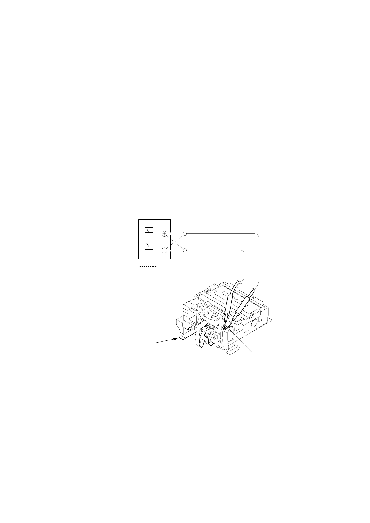
2. TO TAKE OUT A CASSETTE WHEN NOT EJECT (FORCE EJECT)
1 Refer to 2-3. to remove the upper handle block assembly.
2 Refer to 2-5. to remove the cabinet (L) assembly.
3 Refer to 2-5. to remove the mechanism deck (Including VC-242D board and DD-138D board).
4 Remove DD-138D board from the mechanism deck (Including VC-242D board).
5 Remove the CN022 (27P 0.3 mm) of VC-242D board.
6 Supply +4.5V from the DC power supply to the loading motor and unload with a pressing the cassette compartment.
DC power supply (+4.5V)
: loading
: unloading
Disconnect from CN022 (27P)
of VC-242D board.
Loading motor
What to do when a user forgets a password
This camcorder has the forced log insertion function. A passw ord is inputted, and this function is set up. When this function was set up, this
camcorder doesn’t move if the memory stick which memorize a correct logo isn’t inserted. To release the for ced logo function, the correct
password must be input.
This password is memorized in the IC1105 (EEPROM) on VC-242D board. Therefore, when a user for gets the password, replace the IC1105.
This IC1105 memorizes the HRS METER data (Hour meter data: page A, address 00 to 13), too. Therefore, replace the IC1105 in the
following order to copy the HRS METER data.
Replacing procedure:
1) Note down the data of page A, address 00 to 13.
2) Replace IC1105 (EEPROM) on VC-242D board.
3) To page A, address 00 to 13, input the data noted down.
(Refer to “HRS METER (Hours meter)” of “5-4. SERVICE MODE”)
— 7 —
Page 8
SELF-DIAGNOSIS FUNCTION
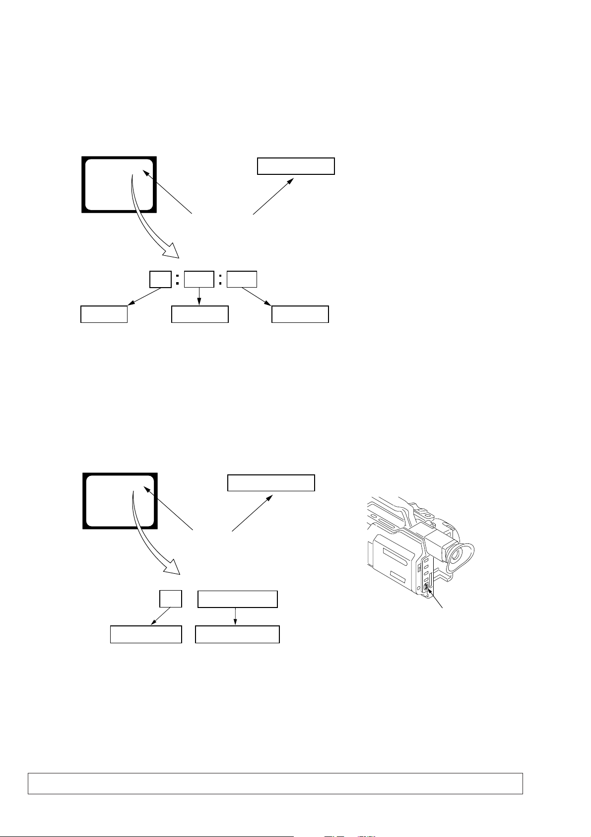
Control dial
1. SELF-DIAGNOSIS FUNCTION
When problems occur while the unit is operating, the self-diagnosis
function starts working, and displays on the viewfinder , LCD screen
or LCD window what to do. This function consists of two display;
self-diagnosis display and service mode display.
Details of the self-diagnosis functions are provided in the Instruction
manual.
Viewfinder or LCD screen LCD window
C : 3 1 : 1 1
Blinks at 3.2Hz
1 1
Repaired by:
C : Corrected by customer
H : Corrected by dealer
E : Corrected by service
engineer
C
Indicates the appropriate
step to be taken.
E.g.
31 ....Reload the tape.
32 ....Tu r n o n power again.
3 1
Block
2. SELF-DIAGNOSIS DISPLAY
When problems occur while the unit is operating, the counter of the
viewfinder, LCD screen or LCD window consists of an alphabet
and 4-digit numbers, which blinks at 3.2 Hz. This 5-character display
indicates the “repaired by:”, “block” in which the problem occurred,
and “detailed code” of the problem.
C : 3 1 : 11
Detailed Code
Refer to page 9.
Self-diagnosis Code Table.
3. SER VICE MODE DISPLAY
The service mode display shows up to six self-diagnosis codes shown in the past.
3-1. Display Method
While pressing the “STOP” key, set the switch from OFF to “VCR or PLAYER”, and continue pressing the “STOP” key for 5 seconds
continuously. The service mode will be displayed, and the counter will show the backup No. and the 5-character self-diagnosis codes.
Viewfinder or LCD screen
[3] C : 3 1 : 1 1
Lights up
[3]
Backup No.
Order of previous errors
C : 3 1 : 1 1
Self-diagnosis Codes
3-2. Switching of Backup No.
By rotating the control dial, past self-diagnosis codes will be shown in order. The backup No. in the [] indicates the order in which the
problem occurred. (If the number of problems which occurred is less than 6, only the number of problems which occurred will be shown.)
[1] : Occurred first time [4] : Occurred fourth time
[2] : Occurred second time [5] : Occurred fifth time
[3] : Occurred third time [6] : Occurred the last time
LCD window
3 C : 3 1 : 11
3-3. End of Display
Turning OFF the power supply will end the service mode display.
Note: The “self-diagnosis display” data will be backed up by the coin-type lithium battery of CK-093 board BT250. When CK-093 board is removed,
the “self-diagnosis display” data will be lost by initialization.
— 8 —
Page 9

4. SELF-DIAGNOSIS CODE TABLE
Self-diagnosis Code
Function
Repaired by:
C
C
C
C
C
C
C
C
C
C
C
C
C
C
C
C
C
C
C
C
C
C
C
E
E
E
E
Block
04
21
22
31
31
31
31
31
31
31
31
31
31
31
31
32
32
32
32
32
32
32
32
61
61
62
62
Detailed
Code
00
00
00
10
11
20
21
22
23
24
30
40
42
10
11
20
21
22
23
24
30
40
42
00
10
00
01
Symptom/State
Non-standard battery is used.
Condensation.
Video head is dirty.
LOAD direction. Loading does not
complete within specified time
UNLOAD direction. Loading does not
complete within specified time
T reel side tape slacking when unloading
Winding S reel fault when counting the
rest of tape.
T reel fault.
S reel fault.
T reel fault.
FG fault when starting capstan.
FG fault when starting drum.
FG fault during normal drum operations.
LOAD direction loading motor time-
out.
UNLOAD direction loading motor
time-out.
T reel side tape slacking when
unloading.
Winding S reel fault when counting the
rest of tape.
T reel fault.
S reel fault.
T reel fault.
FG fault when starting capstan.
FG fault when starting drum
FG fault during normal drum
operations
Difficult to adjust focus
(Cannot initialize focus.)
Zoom operations fault
(Cannot initialize zoom lens.)
Steadyshot function does not work well.
(With pitch angular velocity sensor output
stopped.)
Steadyshot function does not work well.
(With yaw angular v elocity sensor output
stopped.)
Correction
Use the info LITHIUM battery.
Remove the cassette, and insert it again after one hour.
Clean with the optional cleaning cassette.
Load the tape again, and perform operations from the beginning.
Load the tape again, and perform operations from the beginning.
.
Load the tape again, and perform operations from the beginning.
Load the tape again, and perform operations from the beginning.
Load the tape again, and perform operations from the beginning.
Load the tape again, and perform operations from the beginning.
Load the tape again, and perform operations from the beginning.
Load the tape again, and perform operations from the beginning.
Load the tape again, and perform operations from the beginning.
Load the tape again, and perform operations from the beginning.
Remove the battery or power cable, connect, and perform
operations from the beginning.
Remove the battery or power cable, connect, and perform
operations from the beginning.
Remove the battery or power cable, connect, and perform
operations from the beginning.
Remove the battery or power cable, connect, and perform
operations from the beginning.
Remove the battery or power cable, connect, and perform
operations from the beginning.
Remove the battery or power cable, connect, and perform
operations from the beginning.
Remove the battery or power cable, connect, and perform
operations from the beginning.
Remove the battery or power cable, connect, and perform
operations from the beginning.
Remove the battery or power cable, connect, and perform
operations from the beginning.
Remove the battery or power cable, connect, and perform
operations from the beginning.
Inspect the lens block focus reset sensor (Pin wg of LA-026 board)
when focusing is performed when the control dial is rotated in the
focus manual mode, and the focus motor drive circuit (IC140 of
LA-026 board) when the focusing is not performed.
Inspect the lens block zoom reset sensor (
when zooming is performed when the zoom lens is operated and
the zoom motor drive circuit (IC140 of LA-026 board) when
zooming is not performed.
Inspect pitch angular velocity sensor (SE601 or SE602 of SE-108
board) peripheral circuits.
Inspect yaw angular velocity sensor (SE600 or SE603 of SE-108
board) peripheral circuits.
Pin ws of LA-026 board
)
— 9 —
Page 10
SECTION 1
GENERAL
DSR-PD150/PD150P
This section is extracted from instruction
manual. (DSR-PD150P)
1-1
Page 11
1-2
Page 12
1-3
Page 13
1-4
Page 14
1-5
Page 15
1-6
Page 16
1-7
Page 17
1-8
Page 18
1-9
Page 19
1-10
Page 20
1-11
Page 21
1-12
Page 22
1-13
Page 23
1-14
Page 24
1-15
Page 25
1-16
Page 26
1-17
Page 27
1-18
Page 28
1-19
Page 29
1-20
Page 30

1-21
Page 31

1-22
Page 32

1-23
Page 33

1-24
Page 34

1-25
Page 35

1-26
Page 36

1-27
Page 37

1-28
Page 38

1-29
Page 39

1-30
Page 40

1-31
Page 41

1-32
Page 42

1-33
Page 43

1-34
Page 44

1-35
Page 45

1-36
Page 46

1-37
Page 47

1-38
Page 48

1-39
Page 49

1-40
Page 50

1-41
Page 51

1-42
Page 52

This section is extracted from instruction manual.
(Auto Logo Insert for Copyright Protection)
1-43
Page 53

1-44
Page 54

1-45E
Page 55

SECTION 2
DISASSEMBLY
The following flow chart shows the disassembly procedure.
DSR-PD150/PD150P
2-1. LCD section
(HL-011, PD-126 boards, Inverter transformer unit)
2-2. EVF section (LB-065D board)
2-3. Upper handle block assembly
2-6. Cabinet (L) block assembly, Mechanism deck,
VC-242D, DD-138D, JK-190 boards
(for force eject of cassette and VTR section check)
2-14. Control switch block (PS-4980),
Control switch block (CF-4980)
2-7. Cabinet (R) block assembly
DSR-PD150/PD150P
2-8. Cabinet bottom (D) assembly 2-15. CK-093 board
HL-011, PD-126 boards service position
LB-065D board service position
2-4. FK-076, MA-386D boards
2-5. XD-001, XS-001, XM-001 boards
FK-076, XD-001, XS-001, XM-001, MA-386D boards
service position
Mechanism deck service position-1
Service position to check the VTR section
CK-093 board service position
2-9. Battery panel block assembly
(MK-014, KP-010, MS-049 boards)
2-10. EVF block assembly
2-11. LA-026, DD-138D, VC-242D, JK-190 boards,
Mechanism deck
2-12. Lens block assembly, Center frame assembly
[Connection diagram for service position (Mainly for voltage measurement and check)]
(CK-093, VC-242D, JK-190, CD-254, DD-138D, LA-026, KP-010, MK-014, MS-049 boards, Mechanism deck-2)
2-16. Control switch block (ED-4980),
Hinge assembly
2-13. CD-254, SE-108 boards, Zoom lens assembly
2-1
Page 56

NOTE: F ollo w the disassembly procedure in the numerical order given.
2-1. LCD SECTION (HL-011, PD-126 BOARDS, INVERTER TRANSFORMER UNIT)
REMOVING THE PD-126 BOARD,
INVERTER TRANSFORMER UNIT
4
Harness
(CP-093) (8P)
6
LCD frame,
BL retainer,
FP-196 flexible
board
5
(CP-094) (14P)
qa
Remove the
three solderings
qh
Inverter transformer
unit
1
FP-195 flexible
board (7P)
q;
Screw
(M1.7 × 2.5),
lock ace
qj
PD-126 board
PCB clip
7
T wo screws
(M1.7 × 2.5), lock ace
qs
Back light
Cold cathode
fluorescent tube
Liquid crystal
P cabinet (M) assembly
qd
PCB clip
PD-126
Board
qf
qg
Remove the
six solderings
9
indicator module (24P)
8
2
T wo screws
(M2 × 3),
spring bolt
Harness
qa
Screw
(M2 × 3),
spring bolt
5
FP-196 flexible
board (5P)
3
P cabinet (C) assembly
q;
9
B
6
2
-1
D
rd
P
a
o
B
slide the HL-011 board in
the direction of the arrow
HL-011 board
Release the two claws and
qs
T wo screws
(M2 × 3), spring bolt
qd
Panel holder
7
Release the two claws and
slide the indication panel
block assembly in the
direction of the arrow A.
A
8
Indication panel
block assembly
6
FP-205 flexible
board (21P)
B
.
3
Three claws
[HL-011, PD-126 BOARDS SERVICE POSITION]
HL-011 board
Indication panel
block assembly (21P)
Adjustment remote
commander (RM-95)
FP-196
flexible board (5P)
6
2
-1
D
rd
P
a
o
B
FP-195
flexible board (7P)
Inverter transformer unit
PD-126 board
2
(M2 × 5),
spring bolt
LANC
jack
AC POWER
ADAPTOR
T wo screws
CPC-13 jig
(J-6082-443-A)
AC IN
4
FP-195 flexible
board (7P)
2
1
T wo screws
(M2 × 5), spring bolt
CN007
20
1
Claw
3
CPC cover
1
Screw
(M2 × 5),
spring bolt
2-2
Page 57

2-2. EVF SECTION (LB-065D BOARD)
A
B
1
Push the lock knob
in the direction of the
arrow A and remove the
EVF rear cabinet assembly
in the direction of the
arrow B.
2
EVF rear
cabinet assembly
4
EVF front cabinet (upper)
6
5
EVF front cabinet
(lower) assembly
3
T wo tapping
screws (M1.7 × 8)
1
FP-193
flexible board (27P)
2
LCD (LCX033AL-J)(16P)
8
LCD (LCX033AL-J)
3
Two claws
4
LB-065D board
5
LCD cushion (498)
6
Illuminator (498)
7
LCD cushion (498)
9
Light interception sheet
q;
LCD holder
assembly
REMOVING THE LB-065D BOARD
LB-065D board
LCD holder assembly
Adjustment remote
commander (RM-95)
LANC
jack
AC POWER
ADAPTOR
AC IN
CPC-13 jig
(J-6082-443-A)
[LB-065D BOARD SERVICE POSITION]
2-3
Page 58

2-3. UPPER HANDLE BLOCK ASSEMBLY
)
4
Tilt up the finder.
2
T wo screws
(M2 × 5),
spring bolt
3
Screw (M2 × 5),
spring bolt
1
Two screws (M2 × 5),
spring bolt
5
Screw
×
(M2
spring bolt
5),
9
Upper handle block assembly
7
6
the finder.
8
FP-200 flexible
board (36P)
Tilt down
2-4. FK-076, MA-386D BOARDS
5
T wo screws
×
(M2
5), spring bolt
4
FK frame
(D) assembly
6
Handle cover (D) assembly
7
Screw (M2 × 3),
spring bolt
9
MA-386D board
8
FP-216 flexible board (20P
1
FP-202 flexible
board (27P)
3
FK-076 board
2
Four screws
(M2 × 3), spring bolt
2-4
Page 59

2-5. XD-001, XS-001, XM-001 BOARDS
7
Screw (M2.6)
8
Cable holder
6
Four screws
(M2.6)
3
T wo screws
(M2 × 5), spring bolt
qa
1
T wo screws
(B3
×
10)
A
2
Microphone holder
assembly
Handle cabinet (R)
qd
T apping screw
(B2 × 5)
qs
FP-218 flexible
board (13P)
qf
XD-001 board,
DD bracket
Remove the XM-001 board
and XLR sheet metal in the
direction of the arrow.
5
Two FP-217 flexible
boards (16P)
A
4
T wo screws
×
(M2
qg
Three T apping screws
(M2
5), spring bolt
×
5)
When installing it, align the five switch
positions as arrow.
0
XM-001 board,
XLR sheet metal
qk
XS-001 board
9
w;
Handle (D) assembly,
(Upper) cabinet
qh
Two tapping screws (B2 × 5)
qj
SW insulated plate
ql
Handle cabinet (L)
assembly
PRECAUTION DURING INSTALLATION
[FK-076, XD-001, XS-001, XM-001, MA-386D BOARDS SERVICE POSITION]
MA-386D board
FP-217 flexible
board (16P)
XM-001 board
FP-218 flexible
board (13P)
XD-001 board
Adjustment remote
commander (RM-95)
LANC
jack
FP-216 flexible
board (20P)
XS-001 board
FP-202 flexible board (27P)
FK-076 board
AC POWER
ADAPTOR
CPC-13 jig
(J-6082-443-A)
AC IN
2-5
Page 60

2-6. CABINET (L) BLOCK ASSEMBLY, MECHANISM DECK,
VC-242D, DD-138D, JK-190 BOARDS
(FOR FORCE EJECT OF CASSETTE AND VTR SECTION CHECK)
(FOR FORCE EJECT OF CASSETTE)
4
Screw
(M2 × 3),
spring bolt
5
Flexible retainer
2
FP-200 flexible
board (10P)
1
FP-193 flexible
board (27P)
3
Screw
(M2 × 3),
spring bolt
6
FP-187 flexible
board (50P)
q;
Claw
3
Screw
(M2 × 5),
spring bolt
6
block assembly
4
T wo screws
(M2 × 3),
spring bolt
Cabinet (L)
1
Screw
(M2 × 5),
spring bolt
2
Screw
(M2 × 5),
spring bolt
5
Three screws
(M2 × 5),
spring bolt
7
FP-186 flexible
board (80P)
qa
CD-254 board
(50P)
qd
DC-IN connector (3P)
qs
Battery terminal board (4P)
(FOR VTR SECTION CHECK)
8
JK-190 board (40P)
qf
VC-242D, DD-138D board,
MD frame assembly
1
T wo screws
(M2 × 5),
spring bolt
9
Four screws
(M2 × 3),
spring bolt
Mechanism deck,
-242D
C
V
oard
B
6
Mechanism deck,
VC-242D board,
MD frame assembly
4
FP-191 flexible
board (60P)
2
JK-190 board,
JK frame
2-6
DD138D
5
DD-138D board
3
T wo screws
(M2 × 3),
spring bolt
Page 61

[MECHANISM DECK SERVICE POSITION-1]
Note: Use the parts only which can be removed easily from outside of the mechanism deck.
Adjustment remote
commander (RM-95)
LANC jack
Mechanism deck
CPC-13 jig
(J-6082-443-A)
Cabinet (L) block assembly
AC POWER
ADAPTOR
AC IN
[SERVICE POSITION TO CHECK THE VTR SECTION]
Connection to Check the VTR Section
To check the VTR Section, set the VTR to the "forced VTR power ON" mode.
Operate the VTR functions using the adjustment remote commander (with the HOLD switch set in the OFF position)
(However, connect the cabinet (L) assembly when cassette is going to be ejected only.)
Setting the “Forced VTR Power ON” mode
1) Select page: 0, address: 01, and set data: 01.
2) Select page: D, address: 10, set data: 02, and press
the PAUSE button of the adjustment remote
commander.
AC IN
AC POWER
ADAPTOR
DC-IN
connector (3P)
(1-794-637-11)
DD-138D board
Exiting the “Forced VTR Power ON” mode
1) Select page: 0, address: 01, and set data: 01.
2) Select page: D, address: 10, set data: 00, and press
the PAUSE button of the adjustment remote
commander.
3) Select page: 0, address: 01, and set data: 00.
FP-191 flexible board (60P)
Insert the FP-191 flexible board in the opposite
direction to the normal insertion direction.
CPC-13 jig (J-6082-443-A)
Connect here when the tape path
check is going to be performed.
Cabinet (L) block assembly
Mechanism deck
2-7
VC-242D board
VC-242D
Board
LANC jack
Control switch block (CF-4980) (14P)
(Connect here when cassette is going to be ejected.)
JK-190 board
VIDEO jack
Adjustment remote
commander (RM-95)
Monitor TV
Page 62

2-7. CABINET (R) BLOCK ASSEMBLY
)
4
T wo screws
(M2 × 5),
spring bolt
5
Screw
(M2 × 5),
spring bolt
7
Cabinet (R) block assembly
2
6
T wo screws
(M2 × 5),
spring bolt
1
Screw
(M2 × 5),
spring bolt
3
CF ornamental plate
Claw
[CK-093 BOARD SERVICE POSITION]
Adjustment remote
commander (RM-95)
LANC
jack
2-8. CABINET BOTTOM (D) ASSEMBLY
CK-093
Cabinet (R) block assembly
REMOVING THE FBS COVER ASSEMBLY
Board
CK-093 board
AC POWER
ADAPTOR
CPC-13 jig
(J-6082-443-A
AC IN
3
T ripod table
2
Four screws
×
(M2
spring bolt
5),
1
FP-189
flexible board (6P)
5
Cabinet bottom
(D) assembly
4
Two screws
(M2 × 5),
spring bolt
2-8
1
Two tapping screws
×
(B2
2
FP-189
flexible board
5)
3
Two tapping screws
×
(B2
5)
5
FBS cover
assembly
4
Cabinet (bottom)
Page 63

LA-026
board
MS-049
Board
A
A
1
FP-190
flexible board (20P)
2
DC-IN connector (3P)
3
Battery terminal board (4P)
5
Screw (M2 × 5),
spring bolt
8
Screw (M2 × 5),
spring bolt
9
CPC cover
q;
Battery panel block assembly
4
Screw (M2 × 3),
spring bolt
6
T wo screws
(M2 × 5),
spring bolt
7
T wo screws
(M2
×
5),
spring bolt
1
Two tapping screws (B2 × 5)
8
T wo tapping
screws (B2
×
5)
q;
T wo tapping
screws (B2
×
5)
qa
DC jack retainer
qs
DC-IN connector
9
MS holder assembly
2
MK retainer
3
MK-014 board
When installing it,
align the switch position
as shown.
5
KP-010 board
7
MS-049 board
4
Screw (M2 × 3),
spring bolt
6
T wo screws
(M2
×
3),
spring bolt
PRECAUTION DURING
INSTALLATION
2-9. BATTERY PANEL BLOCK ASSEMBLY (MK-014, KP-010, MS-049 BOARDS)
2-10.EVF BLOCK ASSEMBLY
1
FP-193
flexible board (27P)
6
T wo screws
×
(M2
spring bolt
3),
6
2
-0
A
L
rd
a
o
b
4
Peel off the area
shown by shading.
3
Claw
5
Flexible clamp
7
EVF block assembly
2
Screw (M2 × 3),
spring bolt
2-9
Page 64

2-11.LA-026, DD-138D, VC-242D, JK-190 BOARDS, MECHANISM DECK
1
Screw (M2 × 3),
spring bolt
2
8
Screw (M2 × 3),
spring bolt
3
FP-188
flexible board (6P)
LA-026
Board
1
Flexible retainer
9
LA joint
7
LA-026 board
6
Three screws
(M2 × 3),
spring bolt
5
Flexible board (27P)
(from VAP assembly)
4
Flexible board (39P)
(from zoom lens assembly)
CD-254 board (50P)
8
Two screws (M2 × 2),
lock ace
q;
Mechanism deck
qg
JK-190 board
qs
T wo screws
(M2 × 3),
spring bolt
qd
Two claws
6
Step
screw (M2)
9
LD outer lid
A
B
C
D
5
T wo step
screws (M2)
qa
T wo screws
(M2 × 3),
spring bolt
7
MD frame assembly
VC-242DD
Board
A
D
B
C
LA-026
Board
5
4
VC-242D board
2
T wo screws
(M2 × 3),
spring bolt
3
Three screws
(M2 × 3), spring bolt
1
T wo screws
(M2 × 3),
spring bolt
DD138D
LA-026
Board
2
DD-138D board
4
T wo screws
×
(M2
spring bolt
5),
3
T wo screws
(M2 × 3),
spring bolt
(LA-026 board)
qf
JK frame
2-10
Page 65

2-12.LENS BLOCK ASSEMBLY, CENTER FRAME ASSEMBLY
1
Screw (M2 × 3),
spring bolt
q;
Two screws (M2 × 4),
lock ace
qa
Two screws (M2 × 3),
spring bolt
qs
FP-188 flexible board (6P)
FP-188 flexible board
qd
Center frame assembly
Center frame assembly
6
Screw
(M2 × 3),
spring bolt
7
T wo screws
(M2 × 5),
spring bolt
8
T wo screws
(M2 × 5),
spring bolt
4
Screw (M2 × 3),
spring bolt
5
CJ-064 harness
9
Lens block assembly
Lens block assembly
2
T apping screw
(B2 × 5)
3
CCD cover
When installing it.
Align the swich position.
PRECAUTION DURING INSTALLATION
y
[SERVICE POSITION TO CHECK THE CAMERA SECTION]
Connection to Check the CAMERA Section
To check the CAMERA Section, set the CAMERA to the "forced CAMERA power ON" mode.
Setting the “Forced CAMERA Power ON” mode
1) Select page: 0, address: 01, and set data: 01.
2) Select page: D, address: 10, set data: 01, and press
the PAUSE button of the adjustment remote
commander.
FP-191 flexible board (60P)
Insert the FP-191 flexible board in the opposite
direction to the normal insertion direction.
AC IN
AC POWER
ADAPTOR
DC-IN
connector (3P)
(1-794-637-11)
DD-138D board
Extension cable
(J-6082-496-A) (50P)
VC-242D
Mechanism deck
LANC jack
Adjustment remote
commander (RM-95)
2-11
Exiting the “Forced CAMERA Power ON” mode
1) Select page: 0, address: 01, and set data: 01.
2) Select page: D, address: 10, set data: 00, and press
the PAUSE button of the adjustment remote
commander.
3) Select page: 0, address: 01, and set data: 00.
FP-186 flexible board (80P)
Insert the FP-186 flexible board in the opposite
direction to the normal insertion direction.
LA-026
Board
LA-026 board
Board
VC-242D board
JK-190 board
VIDEO jack
Flexible board (39P)
(from zoom lens assembly)
CD-254 board (50P)
Flexible board (27P)
(from VAP assembly)
Monitor TV
Lens block assembl
Page 66

2-13.CD-254, SE-108 BOARDS, ZOOM LENS ASSEMBLY
4
Three tapping screws
(B2 × 5)
5
SE-108 board
3
Flexible board (6P)
(from zoom lens assembly)
REMOVING THE CD-254 BOARD
9
Zoom lens
(VCL-6012WB)
6
CCD emblem
7
Rubber foot (A)
8
Name ring
REMOVING THE ZOOM LENS ASSEMBLY
4
Ornamental ring assembly
Rotate it in the direction of
the arrow C and remove it
in the direction of the arrow D.
C
D
B
A
1
Tapping screw (M1.7 × 4)
5
VAP assembly
8
Remove the soldering.
9
CJ-064 harness
3
Remove the
sixteen solderings.
2
T wo tapping
screws (B2 × 7)
3
Zoom lens assembly
Rotate it in the direction of
the arrow A and remove it
in the direction of the arrow B.
2
(CCD) flexible
block assembly
6
Prism
assembly
1
Three tapping
screws (M1.7 × 7)
q;
CD-254 board
4
Remove the
sixteen solderings.
5
Remove the
sixteen solderings.
2
Prism cover
1
CCD
heat sink
7
Sheet (CD)
2-14.CONTROL SWITCH BLOCK (PS-4980), CONTROL SWITCH BLOCK (CF-4980)
6
Push the eject knob in
the direction of the arrow,
and open the cassette lid.
Eject knob
q;
Control switch block (CF-4980)
Be careful not to damage
the control switch block's
(CF-4980) flexible.
Cassette lid
9
T wo tapping
screws
(B2
×
5)
5
Control switch block
(PS-4980)
3
(CF-4980)
2
Control switch block (PS-4980)
(8P)
7
Four tapping screws
(B2
×
5)
8
Slider assembly
Control switch block
1
T apping screw
(B2
×
5)
4
Two tapping screws
×
(B2
5)
PRECAUTION DURING
INSTALLATION
Install the slider assembly
while pushing the eject lever
fully to the left (CCW).
Eject lever
2-12
Page 67

VC-242D
Board
LA-026
Board
A
A
B
B
Adjustment remote
commander (RM-95)
AC POWER
ADAPTOR
AC IN
Cabinet (R) block assembly
CK-093 board
FP-187 flexible board (50P)
DC-IN
connector (3P)
(1-794-637-11)
Battery panel assembly
Battery terminal board (4P)
KP-010 board
MS-049 board
MK-014 board
EVF block assembly
FP-193
flexible board (27P)
Mechanism deck
DD-138D board
LA-026 board
VC-242D board
JK-190 board
CD-254 board (50P)
Extension cable
(J-6082-496-A) (50P)
Flexible board (39P)
from zoom lens
assembly
Flexible board (27P)
(from VAP assembly)
Lens block assembly
Control switch block
(PS-4980) (8P)
Control switch block
(CF-4980) (14P)
[CONNECTION DIAGRAM FOR SERVICE POSITION (Mainly for voltage measurement and check)]
CK-093, VC-242D, JK-190, CD-254, DD-138D, LA-026, KP-010, MK-014, MS-049 BOARDS,
MECHANISM DECK-2
CPC-13 jig
(J-6082-443-A)
1
Control switch block
(ED-4980) (6P)
2
FP-197 flexible board (6P)
9
FP-194 flexible board (5P)
3
R flexible
protection sheet
5
T wo screws
(M2
×
3),
spring bolt
q;
Seven screws
(M2 × 3),
spring bolt
qa
Claw
6
SP retainer
plate assembly
4
Speaker (2P)
7
Speaker
8
Speaker holder
qd
Harness (CP-094) (14P)
qs
Harness (CP-093) (8P)
qf
CK-093 board
When installing it.
Align the switch position.
PRECAUTION DURING
INSTALLATION
2-15.CK-093 BOARD
2-13
Page 68

2-16.CONTROL SWITCH BLOCK (ED-4980), HINGE ASSEMBLY
Start the removal work after the LCD section has been removed referring section 2-1.
2
Control switch block
(ED-4980)
1
Bright
button
3
Blind door (D) assembly
2
Hinge lid
1
Three screws
(M2 × 3),
spring bolt
6
Three screws
(M2 × 3),
spring bolt
4
Harness (CP-093) (8P)
5
Harness (CP-094) (14P)
8
Three screws
(M2 × 5),
spring bolt
7
9
A
qa
FP-197
flexible board
9
Screw
(M1.7 × 2.5),
lock ace
5
(front)
q;
Screw
(M1.7 × 2.5),
lock ace
Hinge cover
1
T wo screws
(M1.7 × 2.5),
lock ace
3
Three claws
qs
Hinge
assembly
A
2
Screw
(M1.7 × 2.5),
lock ace
4
(rear)
6
fixed tapes
7
Harness
(CP-093)
Hinge cover
T wo harness
8
Harness
(CP-094)
2-14
Page 69

2-17.CIRCUIT BOARDS LOCATION
R
The circuit boards contained in the zoom lens are not shown.
XM-001
(MIC AMP)
XD-001
(DC/DC CONVERTER SIRCS)
XS-001
(MIC SELECT)
SE-108
(VAP SENSOR)
MA-386D
(AUDIO AMP)
FK-076
(CONTROL SWITCH)
LB-065D
(BACK LIGHT)
CD-254
(CCD IMAGER)
CK-093
(KEY IN)
PD-126
(RGB DRIVE/TG)
INVERTER TRANSFORME
UNIT
HL-011
(LCD DRIVE)
VC-242D
S/H AGC, TG, CAMERA SIGNAL PROCESS,
MS I/F, RS232C I/F, STILL CONTROL, MS DRIVE,
DV SIGNAL PROCESS, REC/PB AMP,
LINE IN/OUT, LINE A/D, RGB DRIVE/TG,
CAMERA CONTROL, DRUM/CAPSTAN MOTOR DRIVE,
HI CONTROL, AU LINE A/D, D/A, LINE AMP
JK-190
(JACK BOARD)
DD-138D
(DC/DC CONVERTER, DC REGULATOR)
LA-026
200m/FOCUS DRIVE, VAP DRIVE,
KEY IN/CONNECTOR
MK-014
(CONTROL KEY)
KP-010
(SELECT DIAL)
MS-049
(MS CONNECTOR)
2-15
Page 70

4
2-18.FLEXIBLE BOARDS LOCATION
The flexible boards contained in the mechanism deck and that in the zoom lens are not shown.
FP-193
FP-202
FP-216
FP-218
FP-217
FP-189
FP-190
FP-196
FP-195
FP-191
FP-200
FP-19
FP-188
CONTROL SWITCH BLOCK
(ED-4980)
CONTROL SWITCH BLOCK
(PS-4980)
FP-187
CONTROL SWITCH BLOCK
(CF-4980)
FP-186
FP-197
FP-205
2-16E
Page 71

SECTION 3
BLOCK DIAGRAMS
DSR-PD150/PD150P
3-1. OVERALL BLOCK DIAGRAM (1/4)
LENS BLOCK
IRIS
ZOOM RESET SENSOR
ZOOM
MOTOR
FOCUS
MOTOR
FOCUS RESET SENSOR 25
ACTIVE PRISM
ACTUATOR
ZOOM
FOCUS
SE601,602
SENSOR
SE600,603
SENSOR
SE-108
BOARD
16
(SEE PAGE
4-69)
M
M
VAP LOCK
RING
RING
PITCH
YAW
DICHROIC
PRISM
IRIS
METER
M
CD-254 BOARD
(4-9)
IC101
G-CH CCD
IMAGER
11,14-16 1-4
(4-9)
IC102
R-CH CCD
IMAGER
1-411,14-16
(4-9)
IC100
B-CH CCD
IMAGER
11,14-16 1-4
(4-9)
IC103
8
31
V1,V2A,V2B,V3
H1,H2,RG,SUB
IC104
(4-9)
8
31
V1,V2A,V2B,V3
H1,H2,RG,SUB
IC105
(4-9)
8
13
V1,V2A,V2B,V3
H1,H2,RG,SUB
(4-70)
DRIVE-
20
17
22
34
36
38
39
28
27ND FILTER SW
29
21
20
15
14
12
22
1
2
4
6
HALL-
ZM RST SENS
ZOOM A,B
FOCUS A,B
FC RST SENS
ND A,B,C
CN050
P DRIV A,B
Y DRIV A,B
P OUT
Y OUT
H
P
Y
IC141
8
IRIS DRIVE
HALL AMP
5
ZOOM MOTOR
DRIVE
IC140
FOCUS MOTOR
DRIVE
(4-71,72)
IC070,071
073-076
ACTIVE PRISM
ACTUATOR DRIVE
10
7
(4-70)
(4-72)
25
20
23
VAP LOCK +,-
VP LOCK SENS
IC072
VAP LOCK DRIVE
(4-70)
MZ F0,F1
3
5
IC144
1,2 8,13
DETECTOR
(4-70)
MF F0,F1
8
9
CN052
IC143
1,2
DETECTOR
8,13 49
(4-72)
CN600
PSD OUT
12
5
YSD OUT
10
3
CN050
IC200
8
PITCH/YAW
SENSOR AMP
12 18
2
LA-026 BOARD(1/4)
VC-242D BOARD(1/4)
CN025
35
35
40
40
43
43
44
44
47
47
19
19
25
25
28
28
29
29
32
32
9
9
3
3
6
6
13
13
18
18
CN100
54
53
41
42
61
62
63
64
65
66
67
68
64
63
66
65
68
67
59
60
53
54
55
56
57
58
56
55
58
57
44
43
46
45
36
35
38
37
48
47
50
49
47
48
50
45
46
43
44
CN051
( ) : Page No. shown in ( ) indicates the page to refer on the schematic diagram.
AGC CONT 1,2
R,B GAIN
R,G,B OFFSET
G
7
R
5
B
9
2111 4814
47
45
46
39
38
IC803
EVR
(4-36)
243
IC801
EEPROM
(4-35)
XM-001 BOARD
(4-93,94)
IC200
IC201
MIC/LINE AMP
IC300
IC301
MIC/LINE AMP
19
IC706
A/D
CONVERTER
21
17
14
SPCK
17
16
(4-94)
IC202
2
LOW
CUT
7
AMP
(4-94)(4-93,94)
IC302
2
LOW
CUT
7
AMP
IRIS PWM
HALL AD
EN1
DIR 1A,1B
EN0
DIR 0A,0B
P PWM
Y PWM
VP LOCK DR
MZ A,B
MF A,B
PS OUT
YS OUT
CN023
V1,V2A,V2B,V3
G CCD OUT
R CCD OUT
B CCD OUT
H1,H2,RG
SUB
IC701,702
CCD
V DRIVE
(4-13)
43
(4-35)
66
IC802
19
20
CONTROL
17
18
82
45
44
61
60
7
10
24
25
22
23
59
58
CAMERA
33
35
48
50
62
X701
27MHz
CAM SO,SI,SCK
HI SO,SI,SCK
ZOOM VR AD
40
31
32
29
28
35
34
31
32
17
29
10
5
9
CH1
MIC/LINE
CH2
MIC/LINE
42 1 3
(4-13) (4-14) (4-16)
IC704
S/H,AGC
2526 19 3837 44
XSHD
CLPDM
XSHP
PBLK
XRS
CLP OB
IC705
TIMING
GENERATOR
(4-14)
CN200
MIC
L
MIC
R
CN300
38
47
26
36
11
1
48
G
D0-09
R
D0-09
B
D0-09
HD,VD
EN1
DIR 1A,1B
EN0
DIR 0A,0B
ZM RST SENS
FC RST SENS
5
CN301
5
CN201
11
2
83
79
99
90
47
77
70
71
62
63
64
59
60
61
58
57
14
15
66
14
3
1
16
11
6
14
3
1
16
11
6
IC771
(U-CORE)
CAMERA
SIGNAL
PROCESS
XS-001 BOARD
(1/2)
CN101
S103
CH1
AUDIO
SLECT
SW
S104
CH2
AUDIO
SLECT
SW
CN102
S102
REC
SELECT
CH1
CH1+CH2
(IC705)SPCK
38
Y0-Y7
45
29
C0-C7
36
49
HD,VD,OE
50
51
HI SO,SI,SCK
ZOOM VR AD
FK-076
BOARD
(1/2)
27
1
26
2
CN1103
CN500 CN501
TO
OVERALL
BLOCK
DIAGRAM
(2/4)
(SEE PAGE
3-3)
36
35
LA-026
BOARD
(2/4)
27
26
CN053
CN051
CH1
2
1
TO
OVERALL
BLOCK
DIAGRAM
CH2
(2/4)
(VC-242D)
(SEE PAGE
3-3)
XD-001
BOARD
(1/2)
CN401
6
CN100
7
7
8
5
6
IC401
DC/DC
8
CONV.
9
(4-89)
SHOE UNREG
CH1 MIC 48V
CH2 MIC 48V
3-1 3-2
Page 72

DSR-PD150/PD150P
3-2. OVERALL BLOCK DIAGRAM (2/4)
VC-242D BOARD(2/4)
SPCK
YO-Y7
Q1008,1004
(4-48)
IC1007
2
2
(4-48)
IC1006
CO-C7
HD,VD,OE
HI SO,SI,SCK
ZOOM VR AD
ZOOM VR AD
HI SO,SI,SCK
SP+,-
OSD CS,SO,SCK
PANEL R,G,B,EVF R,G,B,HD,VD
LANC SIG
CH1
VCA
CH2
VCA
232C ON
(4-46)
IC1001
31
57
(4-48)
IC1008
31
1
1
(4-19)
IC1404
RS232C
Q111
12 9
14 7
HP L
HP R
CH1
CH2
CH1
CH2
CH1
CH1
CH2
75
CH2
JK-190
BOARD(1/2)
J301
S VIDEO
G
J300
VIDEO
J303
LANC
J302
(HEADPHONE)
CH1
J300
AUDIO
CH2
OVERALL
BLOCK
DIAGRAM
(1/4)
(LA-026)
(SEE PAGE
3-2)
TO
OVERALL
BLOCK
DIAGRAM
(1/4)
(SEE PAGE
3-2)
Y
YC
TO
20
20
C
G
22
22
17
17
V
TO OVERALL
BLOCK DIAGRAM
(4/4)
(SEE PAGE
3-8)
LANC SIG/232C RD
35
35
LANC GND/232C TD
37
37
26
26
28
28
CH1
12
12
CH2
9
9
CN006
CN301
CH1
1
CH2
2
CN023
16
( ) : Page No. shown in ( ) indicates the page to refer on the schematic diagram.
SPCK
Y0-Y7 |
C0-C7
HD,VD,DE
IC1301
(TAKO)
39
LINE IN
LINE OUT
48
AGC
ACC
42
Y
18
C
14
V
22
28
X1301
13.5MHz
IF
RXD
TXD
64
IC1001
2
54
55
51
46
(4-46)
(XYZ)
AUDIO
(4-30)
30
910
8
SP+,-
10
I/O
CH1
19
CH2
17
CH1
25
Y
36
C
34
TAKO CK
26
Y
46
C
7
(4-46)
IC1010
2
0dbB
-7odB
7
ATT
SPCK
IC903
68
(ALIGN)
59
A/D
CONVERTER
2
6
25
(4-32)
63
Y0-Y7
52
49
C0-C7
42
38
HD,VD,DE
37
36
34
66
(4-17)
IC1403
16Mbit DRAM
20
|
31
1
13
38
48
AFCK
A0-A8
D0-D15
VSP SO,SCK
(4-46)
IC1002
(ADC&DAC)
D/A CONV.
A/D CONV.
15
16
5
3
2
9
8
12
DATA FROM SFD
DATA TO SFD
SFD BCK
IC1012
58
(4-47)
IC1004
53
49
(XYZ)
AUDIO
60
CHZ
INPUT
(4-48)
250dbB
-7odB
7
ATT
14
15
KASHAON
4
CH2
23
14
15
IC1005
(4-48)
VSP SO,SCK
14
13
EVR
IC1407
37
60
51
46
|
38
49
48
47
82
97
|
106
129
|
111
141
•
142
140 132
(4-17)
(HONEY)
DIGITAL
STILL
PROCESS
41
CN300
(4-23)
199
201
77
|
Y0-Y7
70
68
|
C0-C3
64
63
HD,VD OE
62
61
96
|
Y0-Y7
87
86
C4-C7
|
83
80
HD,VD,OE
79
78
7
SYSCLK(IC1401)
AFCK(IC903)
SPCK(IC705)
(4-25)
8
31
OSD CS
OSD SO
OSD SCK
SYSCLK
20
19
18
•
|
17
COL3
•
•
1416190
VSP SO, SCK
HI SO,SI SCK
34
41
IC302
CHARACTER
GENERATOR
12
|
JID0-JID7
21
144143
JID0-JID7
203
207
213
57
17
21
23
200
208
214
4
2
11
9
18
22
24
196
48
HD
184
VD
••
183
195COL0
•
194
•
191
•
IC1409
JPEG
18
205
211
215
31
202
206204
212
216
6
13 15
27
2,9-16
58-64
8
(4-17)
IC301
X1401
7.375MHz
DV SIGNAL
PROCESS
(CAIN)
77
79
88
138
139
142
|
145
51
141
152
153
156
133
132
127
99
97
83
|
88
81
79
170
|
179
159
|
161
75
73
71
105
•
106
67
65
63
55
59
54-52
(4-19)
IC1401
DIGITAL
STILL
CONTROL
5-15 55-75
A0-A10
D0-D15
(4-22)
X301
24.576MHz
L BUS
TRCK
FRRV,TRRV,TRRT
DATA FROM SFD
6
PANEL G
PANEL R
PANEL B
HD,VD
EVF G
EVF R
EVF B
Y
C
19
21
109
112
50
51
LCK
DATA TO SFD
SFD BCK
TXD
RXD
IC1411
XTAL OSC
45
42
47
49
2
4
IC1408
20-31
IC361
DV INTERFACE
(4-20)
IC1406
EEPROM
DI,CI
16Mbit DRAM
2
4
1-13
38-48
(4-26)
(LIP)
X1411
20MHz
(4-21)
CN006
CN023
CN301
626
2
31
31
30
30
33
33
TPA+,-
6
TPB+,-
9
29
MC BUS
37
REC CK
REC DT
AD DT
6
TO
OVERALL
BLOCK DIAGRAM
PB CK
(3/4)
ATF ERR
(SEE PAGE
3-5)
MC BUS
FRRV,TRRV,TRRT
VSP SO,SI,SCK
SPCK1(IC705)
(4-19)
6
IC1412
1
SHUTTER
2
SOUND
SYSCLK(IC1401)
28
36
(4-22)
|
38
IC1410
10
|
MEMORY
1
STICK
•
I/F
48
|
40
SCK
13
4
15
|
17
DV IN/OUT
JK-190
BOARD
(2/2)
MS-049
BOARD
CN051
18
20
17
CN056
LA-026
BOARD(3/4)
MEMORY
STICK
CN776
SLOT
4
8
25
CN775
6
8
3-3 3-4
Page 73

DSR-PD150/PD150P
3-3. OVERALL BLOCK DIAGRAM (3/4)
VC-242D BOARD(3/4)
TO
OVERALL
BLOCK DIAGRAM
(2/4)
(SEE PAGE
3-4)
TO
OVERALL
BLOCK DIAGRAM
(4/4)
(SEE PAGE
3-8)
16
REC CK
REC DT
AD DT
6
PB CK
ATF ERR
MC BUS
FRRV TRRT,TRRV
VSP SO,SI,SCK
HI SO,SI,SCK
CHIME SDA,CHIME SCK,CHIME VDD
XCC DOWN
(4-38)
IC502
EEPROM
2-4
20MHz
FRRV
TRRT
TRRV
95
26
|
37
106
|
108
74
|
76
1
2
X501
83
82
81
( ) : Page No. shown in ( ) indicates the page to refer on the schematic diagram.
CN007
FOR ADJUSTMENTS
32
SWP
RF MON
REC CK
REC DT
(4-37)
IC501
MECHA
CONTROL
60
78
|
80
CAP FG
115
CAP ON,CAP FWD
45
46
CAP PWM
69
DRUM PWM
68
47
DRUM ON,DRUM FWD,DRUM START
48
63
DRUM FG
116
DRUM PG
117
LOAD,UNLOAD
49
50
TREEL FG
114
SREEL FG
113
TAPE END
54
TAPE TOP
53
DEW DET
96
TAPE LED ON
55
REC PROOF SW
44
39
MODE SW A - MODE SW D
|
42
15
20
13
34 31
(2/2)
(4-27)
IC101
(TRF)
EQ
A/D CONV.
PLL
22 24
61
58
Q310
SWITCHING
Q311
SWITCHING
AD DT
6
PB CK
SWP
DRP SO,XDRP SCK
(4-39)
56
IC401
(RABI)
LPF
53
LPF
(2/2)
CN021 CN450
54
454746
52
48
CAP ERROR
DRUM ERROR
(4-109)
18
IC300
PWM
DRIVE
22
DD-138D BOARD(1/2)
PB Y OUT
42
SWP
CN450
393740
38
CN021
C MECHA DECK
(4-28)
IC102
40
(TRW)
42
REC/PB
AMP
27
32
2,3
(4-40)
CAP VS
18.22
DRUM VS
11
(4-39)
16,6,3
1
59
26,25
40
48
34
37
6
7
2
1
CAPSTAN
FG AMP
IC402
CAPSTAN
MOTOR
DRIVE
IC401
(RABI)
DRUM
MOTOR
DRIVE
DRUM FG AMP
DRUM PG AMP
LOADING MOTOR
DRIVE
REEL FG AMP
TAPE END DETECT
TAPE TOP DETECT
CN101
ODD
EVEN 8
(1/2)
5
6
9
14,15
21,23,19
20,22,24
64
61
28,30
42,43
45,46
35
36
(SEE PAGE 4-39)
CN024
CN020
CN022
XCC DOWN
DRUM
24
25
17
|
20
7
|
10
11
|
14
6
|
1
10
11
27
|
24
23
8
9
12
11
21
1
14
3
5
|
7
4
19
|
16
M902
CAPSTAN
M
M
DRUM FG
DRUM PG
M
DEW
SENSOR
T REEL
SENSOR
S REEL
SENSOR
Q901
TAPE END SENSOR
Q902
TAPE TOP SENSOR
D901
TAPE LED
REC PROOF
4PIN
CONNECTOR
C IN
MODE
SWITCH
S903
FG
CAPSTAN
MOTOR
M901
DRUM
MOTOR
M903
LOADING
MOTOR
S902
CN901
S901
3-5 3-6
Page 74

DSR-PD150/PD150P
3-4. OVERALL BLOCK DIAGRAM (4/4)
CN001
CN401
1
2
4
CN255
CN256
2
4
CN254
2
ZOOM VR
START/STOP SW
EJECT SW
LID OPEN SW
CN054
2
3
5
1
6
CN055
3
10
CN056
10
4
CK-093 BOARD(1/2)
S251,253,261
DISPLAY SW
TC/U-BIT SW
DATA CODE SW
S250,255,258,260,263
ZEBRA SW,TITLE SW,
DIGITAL EFECT SW,
MENU SW,
MEMORY MIX SW
S252,254,257,259,262
MEMORY FUNCTION SW
S256
RESET
PHOTO SW
POWER SW
START/STOP SW
(LOW ANGLE)
LA-026 BOARD(4/4)
KP-010
BOARD
XS-001
BOARD(2/2)
CN001
S100,105
+48V
CN103
SW
17
9
BT250
LITHIUM
BATTERY
ZOOM VR AD
XPHOTO FREEZE
XPHOTO REC
XS/S SW
XVTR MODE SW
XCAM+STBY SW
PHOTO STBY SW
XEJECT SW
LID OPEN
MA-386D
BOARD(2/2)
(4-106)
IC1102
COMMANDER
RECEIVER
CN1106
5
SHOE ID1
13
REMOTE
(REAR)
CN250
SEL/PUSH
EXEC
DIAL
PRESET SW
S1101
CUSTUM
40
42
36
34
38
32
46
ED-4980
BOARD
FP-197
(FLEXIBLE)
FP-194
(FLEXIBLE)
CONTROL
SWITCH BLOCK
(CF4980)
(SEE PAGE 4-86)
FP-189
(FLEXIBLE)
FP-188
(FLEXIBLE)
MK-014
BOARD
XD-001
BOARD(2/2)
16
IRIS
DIAL
IRIS SW
PANEL OPEN/
CLOSE SW
PANEL
REVERSE SW
REC LEVEL SW
FADER SW
BACK LIGHT SW
STOP LIGHT SW
INDEX SW
FOCUS SW
S001-005
AE SHIFT SW
AUTO WHITE BALANCE SW
SHUTTER SW
GAIN SW
AUTO LOCK SW
IC400
REMOTO
COMMANDER
RECEIVER
(FRONT)
(4-90)
1
( ) : Page No. shown in ( ) indicates the page to refer on the schematic diagram.
DIAL C
KEY AD5
20MHz OUT
20MHz IN
32KHz IN
32KHz OUT
KEY AD4
KEY AD6
XRESET
VDD
XPHOTO FREEZE
KEY AD8
XS/S SW
XVTR MODE SW14
XCAM+STBY SW
XPHOTO STBY SW
XEJECT SW
LID OPEN
KEY AD2
KEY AD3
DIAL B
MELODY
SIRCS ENV
HOT SHOE ID1
XSIRCS IN
KEY AD0
IB SI
IB SO49
LANC I/O
(4-43)
(4-44)
IC1104
HI CONTROL
BATT/EXT SW
FAST CHARGE
CAM DD ON
Q1104
I/F
10
12
VC-242D BOARD(4/4)
DIAL C,D
40
42
KEY AD5
36
KEY AD4
34
KEY AD6
38
HI XRESET
32
LI 3V
46
CN008
CN009
3
4
5
6
7
8
9
10
12
13
CN550
CN1103
1
1
6S550
2
22
10
8
24
21
VTR UNREG
BATT UNREG
1
6
2
CN056
FK-076
BOARD(2/2)
LANC SIG
6
18
20
SIRCS SIG
4
7
CN500
S500-511
VTR
FUNCTION SW
CN501
3
7
EXCUTE(DIAL)
15
27
29
13
16
17
6
7
IC1102
KEY AD2
KEY AD3
DIAL A,B
6
18
20
4
7
8
CN053
RESET
VDD SWITCH
(4-43)
CN051
82
83 DIAL D
98
40
X1101
20MHz
41
52
X1102
32.768KHz
53
97
99
5
6
29
30
24
23
27
28
25
26
28
27
22
21
9
10
7
8
22
24
19
20
20
19
CN023
7
8
CN004
Q1102,1105
LANC
SIG
38
42
51
77
87
19
92
16
15
20
17
31
95
96
9798DIAL A
36
59
80
70 HOT SHOE ID2
4
93
94 KEY AD1
48
IC1103
11
KEY AD7
CHIME SDA
CHIME SCL
CHIME AD0
CHIME AD2
XCC DOWN
HI SCK 35
OSD SI
OSD SO
OSD SCK
VTR DD ON
SHOE ONMOD
LANC OUT
CK-093
BOARD(2/2)
HL-011 BOARD
CN1702
(4-102)
100
5
6
71
73
18
HI SO
33
HI SI
34
HI SO,SI,SCK
CHIME SDA
CHIME SCK
CHIME VDD
XCC DOWN
TO
OVERALL
BLOCK
DIAGRAM
(3/4)
(SEE PAGE
3-5)
HI SO,SCK
IC1105
EEPROM4
3
2
HI SO,SCK
EVF R,G,B
XHD
XVD
(4-44)
BATT SIG
44
45
46
66
50
29
28
81
12LANC IN
22
20
16
18
29
31
35
37
9
11
41
43
CN008
PANEL R,G,B
XHD,XVD,SP+,SP-
OSD,CS,SO,SCK
HI,SO,SI,SCK
ZOOM VR AD
SHOE UNREG
P UNREG
VTR UNREG
BATT UNREG
22
20
16
18
29
31
35
37
9
11
41
43
48
47
46
40
39
46
45
42
1
48
EVF R,G,B
LANC SIG
CN250
SP+,-
CN253
(4-34)
IC1802
RGB
DRIVE
(4-34)
IC1803
TIMING
GENERATOR
TO
OVERALL
BLOCK
DIAGRAM
(2/4)
(SEE
PAGE
3-3)
SHOE ON
KEY AD7
OSD SO,SCK
PANEL R,G,B
1
2
XHD
XVD
91
CN021 CN450
CN252
CN251
20
22
24
12
24
14
SP901
SPEAKER
26
24
36
38
34
5
6
30
32
49
51
50
41
46
44
CN1701
5
6
4
5
3
4
PD-126 BOARD
3
3
2
2
1
1
10
10
8
8
13
13
12
12
CN2100
EVF BL-
EVF BL+
25
23
R391,392
35
37
33
Q339
5
6
29
31
50
52
49
42
45
43
VCO
XHD
VR
VG
VB
CAM DD ON
VTR DD ON
14
18
13
12
17
20
EVF BL 4.6V
PANEL 2.8V
PANEL 4.6V
PANEL 13.5V
VTR UNREG
BATT UNREG
FAST CHARGE
BATT/EXT SW
BATT SIG
CN007
FOR
ADJUSTMENTS
EVF 2.8V
EVF 13.5V
D 1.5V
D 1.9V
A 2.8V
AU 2.8V
D 2.8V
TRF 2.8V
D 3.1V
MS 3.1V
A 4.6V
AU 4.6V
RP 4.6V
MT 5.2V
AU 8.0V
CAM 12V
CAM -7V
48
47
46
40
39
46
45
42
48
PANEL 4.6V
1
CN00215
8
7
IC2101
RGB
DRIVE
(4-65)
IC2103
TIMING
GENERATOR
249
25
26
24
27
23
3
8
7
(4-109)
IC300
CONVERTER
IC1701
BL ON
Q2182
3
2
4
1
5
1414
25
20
21
CN200
DC/DC
11 2
LCD
DRIVE
30
20
VR,VG,VB
22
24
PSIG
27
COM
12
10
24
(4-65)
PWMHD OUT
LB-065D BOARD
R,G,B
COM
(4-97)
IC200
Q200
INVERTER
PWM
BACK LIGHT
DRIVE
EVF BL 4.6V
DD-138D
BOARD(2/2)
P UNREG
CN1703
PSIG
COM
CN2104
CN201
Q301
FP-196
(FLEXIBLE)
1
VOLUME SW
LCD BRIGHT SW
5
COM1-4
SEG1-16
LCD
5
4
2
1
4
5
3
6
7
3
2
4
1
5
CN2105
FOR
ADJUSTMENTS
INVERTER
BLOCK
1
2
3
1
3
4
INDICATOR
LCD
UNIT
ND901
J902
DC IN
J901
BATTERY
TERMINAL
BACK
LIGHT
BACK
LIGHT
DRIVE
LCD
UNIT
S
21
HSY
VG
23
15
19
22
14
ND200
BACK
LIGHT
CN301
CN300
3-7 3-8
Page 75

DSR-PD150/PD150P
3-5. POWER BLOCK DIAGRAM (1/3)
DD-138D BOARD
Q329,
CHARGE
SWITCH
CHARGE INH
Q302-304
339
F300
F301
F305
F304
F303
F302
INIT CHARGE ON
J901
BATTERY
TERMINAL
S
J902
DC IN
1
2
3
4
1
2
3
CN301
BATT UNREG
DCPACK SW
BATT SIG
ACV UNREG
BATT/XEXT
CN300
Q300,
301
BATT FET ON
SHOE ON
( ) : Page No. shown in ( ) indicates the page to refer on the schematic diagram.
BATT UNREG
4
1
Q305
SWITCHING
Q306,
307
EMERGENCY
T300
5
7
8
2
3
DETECT
D306
RECT
D307
RECT
D305
RECT
VREF
VTR DD ON
D308
55
28
46
57
49
60
8
7
3
27
33
34
35
29
30
VCC(0)1234
VCC(0)5678
VCC
VSS(0)1234
VSS(0)567
VDD(0)123
VDD(0)567
+IN8
-IN8
OUT8
VREF
VB
RT
CT
CTL1-6,8
CTL7
IC300
DC/DC CONVERTER
(4-109)
OUT7-1
OUT7-2
-IN7
OUT3-1
OUT3-2
-IN3
OUT2-1
OUT2-2
-IN2
OUT4
-IN4
COMP
OUT1-1
OUT1-2
-IN1
OUT6-1
OUT6-2
+IN6
OUT5-1
OUT5-2
+IN5
Q312
SWITCHING
64
12
13
Q313
SWITCHING
53
54
40
Q314
SWITCHING
50
51
43
Q308
SWITCHING
56
37
11
47
48
44
61
62
18
58
59
22
Q309
SWITCHING
Q310
SWITCHING
Q311
SWITCHING
4
1
CHARGE INH
44
SHOE ON
33
BATT SIGSHOE UNREG
43
INIT CHARGE ON
27
VTR DD ON
31
CAM DD ON
29
FAST CHARGE
42
BATT/XEXT SW
45
BATT UNREG
R391,392
49
54
MT 5.2V
56
VTR UNREG
50
52
35
SHOE UNREG
37
P UNREG
5
6
PANEL 2.8V
17
PANEL 13.5V
20
PANEL 4.6V
19
AU 4.6V
30
D 1.9V
51
53
A 2.8V
47
AU 2.8V
28
32
D 2.8V
34
24 D 1.5V
26
AU 8.0V
16
39
D 3.1V
41
A 4.6V
22
RP 4.6V
55
TRF 2.8V
18
CAP VS
40
CAP ERROR
46
DRUM VS
38
DRUM ERROR
48
CAM 12V
13
CAM -7V
15
MS 3.1V
14
EVF 2.8V
21
EVF 13.5V
36
EVF BL-
23
EVF BL+
25
CN450
TO
POWER
BLOCK
DIAGRAM
(2/3)
(VC-242D)
(SEE
PAGE
3-11)
Q315-317,324
MT 5.2V
5.2V
REG
TRF 2.8V
L303
Q321
SWITCHING
L304
Q322
SWITCHING
L305
Q323
SWITCHING
T301
5
6
7
8
2
3
L302
Q318
SWITCHING
L300
Q319
SWITCHING
CAP ERROR
L301
Q320
SWITCHING
DRUM ERROR
D311
RECT
D312
RECT
D309
RECT
CAP VS
DRUM VS
L312
L314
L315
L309
Q325
EMERGENCY
DETECT
D313
RECT
L316
L311
L313
L310
L319
Q333-335,338
Q326,328,336
L307
L306
L308
Q340,341
1.5V REG
IC301
Q327,331,332,337
13.5V REG
Q344,348,349,351
12V REG
-7V REG
8V REG
MS 3.1V
D 3.1V
D 1.9V
D 1.5V
AMP
IC301
AU 8.0V
(4-111)
D 2.8V
AU 2.8V
A 2.8V
PANEL 2.8V
EVF 2.8V
L317
EVF 13.5V
L318
PANEL 13.5V
CAM 12V
CAM -7V
PANEL 4.6V
A 4.6V
RP 4.6V
AU 4.6V
EVF BL 4.6V
16
3-9 3-10
Page 76

DSR-PD150/PD150P
3-6. POWER BLOCK DIAGRAM (2/3)
VC-242D BOARD
SHOE ON
BATT SIG
VTR DD ON
CAM DD ON
MT 5.2V
P UNREG
AU 4.6V
D 1.9V
AU 2.8V
D 2.8V
D 1.5V
AU 8.0V
D 3.1V
RP 4.6V
TRF 2.8V
CAP VS
DRUM VS
CAM 12V
CAM -7V
MS 3.1V
EVF 2.8V
EVF 13.5V
EVF BL-
EVF BL+
A 2.8V
A 4.6V
CN021
43
34
44
28
32
30
41
46
50
53
55
49
51
36
38
5
6
18
19
20
(4-46)
IC1010
CH1
ATT
Q1011
D1103
D1102
SHOE UNREG
VTR UNREG
REG
LANC DC
AU 4.6V
IC1001 IC1002
29
52
54
48
27
31
33
23
25
15
40
42
21
56
17
37
45
39
47
14
16
13
22
L1073
L1801
(4-34)
35
24
26
2017CN007
FOR
D 2.8V
MS 3.1V
16
(XYZ)
A 2.8V
AU 2.8V
D 2.8V
A 4.6V
D 3.1V
RP 4.6V
MT 5.2V
D 1.9V
D 2.8V
FB901
L1001
AUDIO I/O
(ALIGN)
A/D CONV.
L1002
FB1002
L902
(4-32) (4-30)
L802
(4-36)
IC803 IC802 IC801 IC771 IC704 IC706
EVR CAMERA EEPROM
L1803
RGB
DRIVE
(4-19) (4-17) (4-21)(4-17) (4-20)
RS232C 16M SHUTTERDIGITALJPEG EEPROM16M DRAM
FB1401
TO
POWER
BLOCK
DIAGRAM
(1/3)
(DD-138)
(SEE
PAGE
3-10)
CHARGE INH
INIT CHARGE ON
FAST CHARGE
BATT XEXT SW
BATT UNREG
VTR UNREG
SHOE UNREG
PANEL 2.8V
PANEL 13.5V
PANEL 4.6V
CAP ERROR
DRUM ERROR
ADJUSTMENTS
( ) : Page No. shown in ( ) indicates the page to refer on the schematic diagram.
2
1
14
IC1101
IC1103
UNREG
LANC DC
AUDIO
ADC&DAC
FB1301
(4-46)
REG
LANC I/O
3
D1104
3
7
(4-43)
POWER
4
VCC
8
IC1105
(4-43)(4-46)
(4-48) (4-48)
IC1006
-1008
VCA,AMP
REG
EEP ROM
IC1005
EVR
IC1102
BATTER IN
DETECT
Q1106
(4-44)
BTT LI 3V
RESET
L1803
(4-46)
IC1004
(XYZ)
CH2
AUDIO
INPUT
L1004
(4-47)
IC1301IC903 IC301 IC361 IC302
(4-17)
(HONEY)
DIGITAL
STILL
PROCESS
FB1404
(LIP)
DV
FB771 FB772
(U-CORE)
CAMERA
SIGNAL
PROCESS
L102
L103
IC102 IC101
(TRW) (TRF)
AMP A/D CONV.
(TAKO)
VIDEO
LINE IN/OUT
AMP
L1301,1304
L801
(4-35) (4-35)
CONTROL
FB1801
IC1803IC1802
TIMING
GENERATOR
(4-34)
EVF BL 4.6V
EVF VCC
EVF 13.5V
(CAIN)
DV
PROCESS
(4-23) (4-26) (4-25)
IC1407
IC1104
HI CONTROL
BATT SENS
90
ACV SENS
91
5
6
4
8
38
42 51
86 87
61
12
XRESET
VDD
BATT IN
XLANC ON
IC1012
CH2 ATT
(4-38) (4-37)
EEPROM
EVER 3.0V
IC1003
AUDIO
FB101
LINE OUT
AMP
CHARACTER
GENERATERINTERFACESIGNAL
L701
S/H
AGC
(4-16) (4-13) (4-14)
L101
EQ,REC/PB
PLL
(4-27)(4-28)
(4-45)
FB707
CONV.
IC501IC502
FB706
A/D
INIT CHARGE ON
VTR DD ON
CAM DD ON
FAST CHARGE
CHARGE INH
BATT/XEXT
XVTR MODE SW
XCAM+STBY SW
XPHOTO STBY SW
CHIME PWR CONT
(4-48)
MECHA
CONTROL
FB501
L702
MS VCC ON
(4-44)
SHOE ON
IC1403IC1404 IC1409 IC1408 IC1406 IC1401 IC1412
(4-19)
DRAMI/F
FB1402 FB1406 FB1405
FB1403
CONTROL
118
IB SO
IB SI
R1455
FB1407
105
RP 4.6V
D 1.9V
SOUND
81
49
48
25
29
28
50
47
66
14
15
20
7
(4-19)
XREEL
HALL ON
Q1104
JK-190 BOARD
LANC DC
32 32
CN006
CN009
CN301
EVF VCC
11
8
EVF BL 4.6V
9
CN002
D 2.8V
2
7
8
9
ZOOM VR
POWER
VTR
OFF
CAMERA
PHOTO
BATT SIG
I/F
J303
LANC
CONTROL
SWITCH
BLOCK
(CF-4980)
LB-065D
BOARD
CN200 CN201
17
20
21
(4-97)
IC200
INVERTER
BACK
LIGHT
DRIVE
LCD
UNIT
16
(SEE PAGE 4-86)
CN008
44
32
46
8
6
10
2
4
14
CAP_VS
D 2.8V
VTR UNREG
MT 5.2V
CK-093 BOARD
44
32
46
PANEL 4.6V
8
PANEL 2.8V
6
PANEL 13.5V
10
2
P UNREG
4
EVER 3.0V
14
CN250
18
22
IC402
L402
EVF 13.5V
S256
RESET
BT250
LITHIUM BATTERY
D 2.8V
VTR UNREG
SHOE UNREG
AU 2.8V
AU 4.6V
VCC
D 3.1V
D 2.8V
A 4.6V
MT 5.2V
(4-40)
CAPSTAN MOTOR
DRIVE,
CAP FG AMP
CN255
CN251
CN252
CN023
13
25
3
CONTROL SWITCH
BLOCK(ED-4980)
7
5
6
7
6
CN004
6
1
2
15
16
12
14
36
70
72
73
75
78
80
MR VCC
HE VCC
DRUM ERROR
D 2.8V
(SEE PAGE 4-62)
TO
POWER BLOCK
DIAGRAM
(3/3)
(PD-126)
(SEE PAGE 3-13)
TO
POWER BLOCK
DIAGRAM
(3/3)
(FK-076)
(SEE PAGE 3-13)
TO
POWER BLOCK
DIAGRAM
(3/3)
(LA-026)
(SEE PAGE 3-13)
CAP ERROR
DRUM VS
IRIS DIAL
52
54
11
DRUM,CAP ERROR AMP
L401
IC401
(RABI)
DRUM
MOTOR DRIVE
DRUM FG,PG AMP
LOADING
MOTOR DRIVE
REEL FG AMP
TAPE TOP,END DET
(4-39)
HE VCC
MR VCC
Q1109,1108
R424
CHIME PWR CONT
Q402
XREEL HALL ON
R024
CHIME VDD
SENSOR VCC
TAPE LED A
CN024
CN022
15
26
27
7
13
15
CAPSTAN
MOTOR
4PIN
CONNECTOR
T REEL,
S REEL
SENSOR
TAPE LED
C MECHA DECK
(SEE PAGE 4-39)
CD-254 BOARD
(4-9)
L100
(4-9)
L101
(4-9)
L107
IC101
CCD IMAGER
(G-CH)
IC102
CCD IMAGER
(R-CH)
IC100
CCD IMAGER
(B-CH)
(4-9)
(4-9)
(4-9)
(4-22)
IC1410
IC1411
MEMORY
STICK I/FSTILL
Q1404,1405
D 2.8V
(4-14)
IC705
GENERATOR
FB704
TIMING
A 4.6V
CAM DD ON
CAM 12V
CAM -7V
(4-13)
IC701
IC702
CCD
V DRIVE
Q701,702
L710
CN025
L106
CN100
IC103
AMP(G-CH)
L104
IC104
AMP(R-CH)
L105
IC105
AMP(B-CH)
39
39
48
48
38
38
2323
341234
24
24
14
14
88
12
3-11 3-12
Page 77

DSR-PD150/PD150P
3-7. POWER BLOCK DIAGRAM (3/3)
PD-126 BOARD
PANEL 4.6V
7
PANEL 2.8V
5
PANEL 13.5V
MEMORY
STICK
SLOT
POWER BLOCK
(SEE PAGE
3-12)
POWER BLOCK
(SEE PAGE
3-12)
MK-014
BOARD
3 VCC
CN776 CN775
MS-049
BOARD
16
DIAGRAM
(CK-093)
DIAGRAM
(VC-242D)
D003
ACCESS
LED
6
CN2100
TO
(2/3)
P UNREG
7
EVER 3.0V
6
CN2101 7
D 2.8V
UNREG VTR FUNCTION KEY
15
SHOE UNREG
16
AU 2.8V
11
TO
(2/3)
CN001
13
35
69
71
74
76
77
79
49
3
15
49
16
CN051
CN056
AU 4.6V
VCC
D 3.1V
D 2.8V
A 4.6V
MT 5.2V
D 2.8V
LA-026 BOARD
L2103
L2101
L2102
IC2101
RGB DRIVE
(4-65) (4-65)
L2182
L2181
CN053
CN501
5
1
2
12
21
13
22
17
26
15
24
D 3.1V
11
20
MT 5.2V
1
10
D500-511
ILLUMINATION
LED
FK-076 BOARD
(4-70) (4-70) (4-70)
IC143
FOCUS RING
PHASE
DETECTOR
Q073,074
Q076,078
FB140
L140
IC140 IC070-072
ZOOM MOTOR
FOCUS MOTOR
DRIVE
( ) : Page No. shown in ( ) indicates the page to refer on the schematic diagram.
XD-001 BOARD
Q2102,2104
IC2103
TIMING
GENERATOR
4
BL ON
R186R178
IC144
ACTIVE PRISM
ACTUATOR DRIVE
VAP LOCK DRIVE
(4-71,72)(4-70)
14
Q2181,2182
CN500
ZOOM RING
PHASE
DETECTOR
L070
P OFF
12
13
15
14
11
1
CN2104
CN2103
16
15
12
14
17
27
VDD
18
IC1102
CN1103
MA-386D BOARD
L142
IC141
IC142
IRIS DRIVE,
V REF
IC075
IC076
P PWM
Y PWM
AMP
(4-72)
LCD
UNIT
INVERTER
BLOCK
BACK
LIGHT
DRIVE
REMOTE
COMMANDER
RECEIVER
(REAR)
(4-105)
L071
HL-011 BOARD
7
CN1701
D1105
TALLY
LED
(REAR)
R1121R1125
Q200,201
IC073,074
ACTIVE PRISM
ACTUATOR
PRE DRIVE
(4-102)
IC1701
LCD
INDICATOR
DRIVE
CN1106
L200
IC200
PITCH/YAW
SENSOR AMP
L143
L141
L072
L073
(4-72)
D401
TALLY
LED
(FRONT)
R401
67 5 1 98
8
14
9
13
10
12
7
15
1
20
2
CN103
IC400
REMOTE
COMMANDER
RECEIVER
(FRONT)
R408
13 6 5879
S100
CH1 +48V
ON OFF
S105
CH2 +48V
XS-001 BOARD XM-001 BOARD
SE VCC
11
4
CN600
LENS BLOCK
Q140,141
R187
Q072,075
Q077
(4-72)
CN050
CN052
26
32
21
2
10
11
ZMFC SENS VCC
ND SENS VCC
DRIVE +
MZ VCC
MF VCC
VAP VCC
(4-89)
IC401
Q402-411
DC/DC
CONV.
(4-90)
CH2
MIC 48V
LINE
CH1
MIC
AUDIO
SELECT
MIC ATT ON
S104
CH2
AUDIO
SELECT
SE-108 BOARD
PITCH/YAW
SENSOR
ZOOM RESET SENSOR
FOCUS RESET SENSOR
ND FILTER SW
IRIS METER
ZOOM RING
FOCUS RING
ACTIVE PRISM
ACTUATOR
CH1
MIC 48V
S103
CN401
CN100
CN102
CN101
125
413
CN201
5
12
413
CN301
(4-93,94)
XLS 48V
L203
IC200
IC203
CH1
MIC/LINE
AMP
(4-93,94)
XLS 48V
L303
IC300
IC303
CH2
MIC/LINE
AMP
3-13 3-14E
Page 78

SECTION 4
PRINTED WIRING BOARDS AND SCHEMATIC DIAGRAMS
4-1. FRAME SCHEMATIC DIAGRAM (1/3)
DSR-PD150/PD150P
FLEXIBLE
FLEXIBLE
1
2
3
4
5
6
7
8
9
10
11
12
13
1
2
3
4
5
6
7
8
9
10
11
12
13
14
15
16
17
18
19
20
21
22
23
24
25
26
27
16
XM-001 BOARD
16P
CN301
CH2_(+)_ATT
CH2_(+)_COM
CH2_(+)_THR
12345
CH2_(+)_ATT
CH2_(+)_THR
CH2_(+)_COM
CN101
16P
13PCN100
REG__GND
REG__GND
REG__GND
F_TALLY_LED
CH2_MIC48V
CH1_MIC48V
SHOE_UNREG
SHOE_UNREG
D_3.1V
SICS_SIG1
MT_GND
MT_GND
MT_5.2V
27P
CN103
L(CH1)OUT
R(CH2)OUT
REG_GND
REG_GND
EXT_MIC_DET
EXT_MIC_MONO
ZOOM_MIC_CONT
SHOE_ID2
N.C.
SHOE_ID1
N.C.
AU_2.8V
F_TALLY_LED
AU_4.6V
SHOE_UNREG
SHOE_UNREG
D_3.1V
SIRCS_SEL1
TALLY_LED
SIRCS_PWM
XCUSTOM_PRESET
LANC_SIG
SIRCS_SEL2
SIRCS_SIG
MT_GND
MT_GND
MT_5.2V
CN200 CN300
MIC1 MIC2
16PCN201
CH2_(-)_ATT
REG_GND
CH2_GAIN_HIGH
CH2_(-)_COM
REG_GND
CH2_(-)_THR
789
6
FP-217 FP-217
FLEXIBLE
10111213141516
REG_GND
REG_GND
CH2_(-)_ATT
CH2_(-)_THR
CH2_(-)_COM
CH2_GAIN_HIGH
A_4.6V
XLS_48V
CH2_GAIN_LINE
CH2_SIG_OUT
CH2_GAIN_LOW
10111213141516
A_4.6V
CH2_SIG_OUT
XLR_48V_CH2
CH2_GAIN_LINE
CH2_GAIN_LOW
REG_GND
LOW_CUT_ON_CH2
123456789
REG_GND
LOW_CUT_ON_CH2
CN102
16P
XS-001 BOARD
S100
INPUT1
+48V
S103
INPUT1
LEVEL
20PCN103
LOWCUT_ON_CH1
SHOE_ID1
REG_GND
REG_GND
REG_GND
R(CH2)OUT
REG_GND
L(CH1)OUT
123456789
21
REG_GND
REG_GND
REG_GND
L(CH1)OUT
R(CH2)OUT
21P
CN106
LOWCUT_ON_CH2
REG_GND
1011121314151617181920
FP-216
FLEXIBLE
REG_GND
REG_GND
SHOE_ID1
LOWCUT_ON_CH2
LOWCUT_ON_CH1
F_TALLY_LED
MA-386D BOARD
CN102 15P
SHOE_UNREG_GND
SHOE_UNREG_GND
SHOE_UNREG_GND
SHOE_UNREG_GND
13PCN401
REG__GND
REG__GND
REG__GND
F_TALLY_LED
CH2_MIC48V
CH1_MIC48V
SHOE_UNREG
SHOE_UNREG
SIRCS_SIG1
REG_GND
REG_GND
SHOE_ID2
SHOE_ID1
AU_2.8V
AU_4.6V
D_3.1V
LANC_SIG
MT_GND
MT_GND
MT_5.2V
D_3.1V
MT_GND
MT_GND
MT_5.2V
N.C.
N.C.
154
13
12
11
10
9
8
7
6
5
FP-128
4
3
2
1
27
26
25
24
23
22
21
20
19
18
17
16
15
14
13
12
FP-202
11
10
9
8
7
6
5
4
3
2
1
ZOOM_B
10
123456789
NC
ZOOM_A
ZOOM_B-
39PCN050
1
26 18
A
LENS
UNIT
B
C
Y_DRIV_A
Y_DRIV_B
VAP_GND
1011121314151617181920212223242526
MF_F1
MF_F0
MF_GND
TEMP_OUT
MZ_F0
MZ_F1
MZ_GND
P_OUT
MF_VCC
VAP_VCC
D
27
NC
LOCK+
Y_OUT
LOCK-
LOCK_SENS_IN
LOCK_SENS_OUT
P_DRIV_A
P_DRIV_B
P_DUMP_A
P_DUMP_B
Y_DUMP_A
Y_DUMP_B
MZ_VCC
5
CCD
IMAGER
CCD
IMAGER
CCD
IMAGER
123456789
39
NC
FOCUS_A-
27P
CN052
FOCUS_B
NC
NC
FOCUS_B-
FOCUS_A
NC
ND_SENS_VCC
NDC
GND
GND
NDA
NDB
FC_RST_SENS
FZ_SENS_VCC
TEMP_OUT
DRIVE+
ZM_RST_SENS
DRIVE-
NC
NC
NC
HALL-
8
CD-254 BOARD
SE-108
BOARD
BIAS+
BIAS-
HALL+
PS_REF
SE_VCC
PSD_OUT
1011121314151617181920212223242526272829303132333435363738
YSD_OUT
YS_REF
6P
CN600
GND2YS_REF3YSD_OUT4SE_VCC5PSD_OUT6PS_REF
1
NC
NC
GND
ZOOM_A-
E
MS-049 BOARD
F
MEMORY
STICK
CONNECTOR
G
CN776
10VSS
9VCC
8SCLK
7N.C.
6INS
5N.C.
4DIO
3VCC
2BS
1VSS
10P
SCLK
8
MS_IN
7
DIO
6
BS
5
VCC
4
VCC
3
REG_GND
2
REG_GND
CN775
1
8P
MK-014 BOARD
H
I
J
K
L
M
N
O
16
S001
GAIN
S002
SHUTTER
SPEED
S003
WHT BAL
S004
AE SHIFT
S005
AUTO LOCK
HOLD
KP-010 BOARD
S550
SEL/PUSH EXEC
FP-189
FLEXIBLE
S501
FADER
S502
BACK LIGHT
S503
SPOTLIGHT
FP-188
FLEXIBLE
FOCUS
S550
INDEX MARK
S551
PUSH AUTO
S552
AUTO
MAN
INFINITY
CN001
CN550
6
5
4
3
2
1
6
5
4
3
2
1
XACCESS_LED
KEY_AD3
D_2.8V
6P
6P
N.C.
SPOT_LIGHT
GND
BACK_LIGHT
GND
N.C.
INFINITY
GND
AUTO/PUSH_AUTO
GND
INDEX
LA-026 BOARD
(1/3) LA BLOCK
N.C
1
2
3
4
GND
5
GND
6
FP-190
FLEXIBLE
6DIAL_B
5GND
4GND
3GND
2EXECUTE
1DIAL_A
6P
CN054
6PCN055
20 SCLK
19 MS_IN
18 DIO
17 BS
16 VCC
15 VCC
14 GND
13 GND
12 N.C
11 XACCESS_LED
10 KEY_AD3
9 D_2.8V
8 GND
7 GND
6 DIAL_B
5 GND
4 GND
3 GND
2 EXECUTE
1 DIAL_A
20PCN056
(2/3) LD BLOCK
(3/3) CN BLOCK
CN053
XCUSTOM_PRESET
LOW_CUT_ON_CH2
LOW_CUT_ON_CH1
27P
MT_5.2V
MT_GND
MT_GND
SIRCS_SIG
SIRCS_SEL2
LANC_SIG
SIRCS_PWM
TALLY_LED
SIRCS_SEL1
SHOE_UNREG
SHOE_UNREG
F_TALLY_LED
AU_4.6V
AU_2.8V
SHOE_ID1
SHOE_ID2
ZOOM_MIC_CONT
EXT_MIC_MONOFADER
EXT_MIC_DET
REG_GND
REG_GND
R(CH2)IN
L(CH1)IN
D_3.1V
11
CN100 50P
1
GND
3
H1B
5
SUBB
7
GND
9
B_CCD_OUT
11
GND
13
V2BB
15
V3B
17
GND
19
R_CCD_OUT
21
GND
23
VDD2R
25
V2AR
27
V1R
29
H1R
31
SUBR
33
GND
35
G_CCD_OUT
37
GND
39
VDD2G
41
V2AG
43
V1G
45
H1G
47
SUBG
49
GND
CN051
80P
R(CH2)IN
1
REG_GND
3
EXT_MIC_MONO
5
SHOE_ID2
7
SHOE_ID1
9
AU_2.8V
11
AU_4.6V
13
SHOE_UNREG
15
TALLY_LED SIRCS_SEL1
17
XCUSTOM_PRESET
19
SIRCS_SEL2
21
SIRCS_SIG
23
CTRL_B
25
CTRL_A
27
KEY_AD2
29
DIO
31
BS
33
VCC
35
C_RST
37
TEMP_OUT
39
HALL_AD
41
PS_OUT
43
YS_OUT
45
MF_A
47
MF_B
49
MF_LED
51
ND_SW1
53
ND_SW2
55
ND_SW3
57
FC_RST_SENS
59
ZM_RST_SENS
61
EN1
63
DIR_1A
65
DIR_1B
67
D_3.1V
69
D_3.1V
71
MT_GND
73
MT_GND
75
MT_5.2V
77
MT_5.2V
79
1
2
3
4
5
6
7
8
9
10
11
12
13
14
15
16
FP-200
FLEXIBLE
17
18
19
20
21
22
23
24
25
26
27
REG_GND
EXT_MIC_DET
ZOOM_MIC_CONT
LOW_CUT_ON_CH1
LOW_CUT_ON_CH2
F_TALLY_LED
SHOE_UNREG
SIRCS_PWM
LANC_SIG
MS_LED_ON
EXECUTU(DIAL)
REG_GND
VP_LOCK_DR
VP_LOCK_SENS
VAP_DD_ON
IRIS_COM
IRIS_PWM
ZM_FC_LED
ND_MZ_LED
IRIS_GAIN
IRIS_OFFSET
REG_GND
REG_GND
CN501
1 UNREG
2 UNREG
3 XSW_LED_VTR
4 XSW_LED_VTR
5 D_2.8V
6 KEY_AD0
7 KEY_AD1
8GND
9GND
10 MT_5.2V
11 MT_GND
12 MT_GND
13 SIRCS_SIG
14 SIRCS_SEL2
15 LANC_SIG
16 XCUSTOM_PRESET
17 SIRCS_PWM
18 TALLY_LED
19 SIRCS_SEL1
20 D_3.1V
21 SHOE_UNREG
22 SHOE_UNREG
23 F_TALLY_LED
24 AU_4.6V
25 LOW_CUT_ON_CH2
26 AU_2.8V
27 SHOE_ID1
28 LOW_CUT_ON_CH1
29 SHOE_ID2
30 ZOOM_MIC_CONT
31 EXT_MIC_MONO
32 EXT_MIC_DET
33 REG_GND
34 REG_GND
35 R(CH2)OUT
36 L(CH1)OUT
CONTINUED ON
(SEE PAGE 4-3)
12 13
CN025
2
GND
4
H2B
6
RGB
8
VDDB
10
GND
12
VLB
14
VDD2B
16
V2AB
18
V1B
20
GND
22
GND
24
VLR
26
V2BR
28
V3R
30
H2R
32
RGR
34
VDDR
36
GND
38
VLG
40
V2BG
42
V3G
44
H2G
46
RGG
48
VDDG
50
GND
L(CH1)IN
2
4
6
8
10
12
14
16
18
20
22
KEY_AD3
24
26
28
SCLK
30
MS_IN
32
34
36
38
40
VP_TEMP
42
P_OUT
44
Y_OUT
46
MZ_A
48
MZ_B
50
52
54
P_PWM
56
Y_PWM
58
60
62
EN0
64
DIR_0A
66
DIR_0B
68
70
72
D_2.8V
74
A_4.6V
76
78
80
36P
FK-076 BOARD
CONTINUED ON
(SEE PAGE 4-3)
XD-001
BOARD
CONTINUED ON
(SEE PAGE 4-3)
S500
STOP
S501
PAUSE
S502
REW
S503
FF
S504
PLAY
S505
SLOW
S506
REC
S507
REC
S508
AUDIO DUB
S509
EDIT SEARCH +
S510
END SEARCH
S511
EDIT SEARCH -
1473
CN500
XCUSTOM_PRESET
27P
L(CH1)OUT
R(CH2)OUT
EXT_MIC_DET
EXT_MIC_MONO
ZOOM_MIC_CONT
F_TALLY_LED
SHOE_UNREG
SHOE_UNREG
SIRCS_SEL1
TALLY_LED
SIRCS_PWM
SIRCS_SEL2
SIRCS_SIG
19
CH1_(-)_ATT
REG_GND
CH1_(+)_COM
CH1_(+)_THR
CH1_(-)_COM
CH1_(+)_ATT
123456789
FLEXIBLE
REG_GND
CH1_(-)_ATT
CH1_(+)_ATT
CH1_(+)_THR
CH1_(-)_COM
CH1_(+)_COM
S102
REC CH
SELECT
S104
INPUT2
LEVEL
AU_4.6V
F_TALLY_LED
SIRCS_PWM
SHOE_UNREG
SHOE_UNREG
D_3.1V
SIRCS_SIG1
1011121314151617181920
N.C.
D_3.1V
AU_4.6V
SIRCS_SIG1
SHOE_UNREG
SHOE_UNREG
1
SHOE_UNREG
2
SHOE_UNREG
3
SHOE_UNREG
4
SHOE_UNREG
5
LANC_SIG
6
SHOE_ID1
7
SHOE_ID2
8
SHOE_MIC_GND
9
SHOE_MIC_GND
10
SHOE_MIC_GND
11
SHOE_MIC_L
12
13
14
15
REG_GND
CH1_(-)_THR
10111213141516
REG_GND
CH1_(-)_THR
MT_GND
MT_GND
MT_GND
FLEXIBLE
FP-201
CH1_GAIN_HIGH
CH1_GAIN_HIGH
MT_GND
MT_5.2V
209 17
CH1_GAIN_LOW
CH1_GAIN_LINE
XLS_48V
A_4.6V
10111213141516
A_4.6V
XLR_48V_CH1
CH1_GAIN_LINE
CH1_GAIN_LOW
S105
INPUT2
+48V
MT_5.2V
123456789
MT_5.2V
INTELLGENT
ACCESSSORY
SHUE
CH1_SIG_OUT
REG_GND
REG_GND
CH1_SIG_OUT
LOW_CUT_ON_CH1
123456789
LOW_CUT_ON_CH1
FRAME SCHEMATIC DIAGRAM (1/3)
4-1 4-2
Page 79

DSR-PD150/PD150P
FRAME SCHEMATIC DIAGRAM (2/3)
J301
S-VIDEO
LANC_SIG/232C_RD
LANC_GND/232C_TD
GND
GND
LANC_SIG/232C_RD
LANC_GND/232C_TD
14P
CN009
D_2.8V
ZOOM_VR_AD
GND
123456789
XLANC_JACK_IN
GND
GND
XLANC_JACK_IN
6
LANC_DC
LANC_DC
GND
GND
7
J300
VIDEO
CH1
CH2
HP_JACK_IN
HP_L_OUT
HP_R_OUT
GND
GND
HP_R_OUT
HP_L_OUT
1/18 CA(CH) BLOCK
2/18 CA(U-C) BLOCK
3/18 MS-1 BLOCK
4/18 MS-2 BLOCK
5/18 MS-3 BLOCK
6/18 JC-1 BLOCK
7/18 JC-2 BLOCK
8/18 RF BLOCK
9/18 IO BLOCK
GND
XSDL
XODD
YODD
GND
XSDL
YODD
XODD
VIDEO
HEAD
VIDEO HEAD
GND
GND
GND
GND
GND
YEVEN
GND
YEVEN
ODD
CH
GND
GND
HP_JACK_IN
GND
YSDL
123456789
123456789
GND
YSDL
EVEN
CH
AUDIO
CN300
DV IN/OUT
S_C_I/O
S_Y_I/O
XS_JACK_IN
XS_JACK_IN
S_C_I/O
V_JACK_IN
GND
GND
GND
GND
S_Y_I/O
V_JACK_IN
VC-242D BOARD
10P
11PCN020
CN101
GND
DRUM_W
XEVEN
123456789
10
123456789
10
10P
GND
11P
XEVEN
DRUM_W
VIDEO_I/O
VIDEO_I/O
DRUM_W
DRUM_W
8
9
10
11
12
13
LB-065D BOARD
AUDIO_R_I/O
RCH_DET
10111213141516171819202122232425262728293031323334353637383940
10111213141516171819202122232425262728293031323334353637383940
RCH_DET
AUDIO_R_I/O
SENSOR_VCC
FG
10
10
FG
SENSOR_VCC
J303
LANC
TPA-
TPA+
GND
GND
GND
GND
TPA-
TPA+
27P
CN022
TOP_SENS
PG
123456789
11
123456789
11
PG
27P
TOP_SENS
TPB+
GND
GND
TPB+
GND
REC_PRF_SW
GND
REC_PRF_SW
FP-594
TPB-
TPB-
C_IN_SW
C_IN_SW
GND
123456789
123456789
GND
MIC_SCK
MIC_SCK
40P
CN301
40PCN006
MIC_SDA
MIC_SDA
MIC_VDD
MIC_VDD
REEL_T+
REEL_T+
REEL_T-
REEL_T-
MODE SWITCH
27P
CN200
CN200
27P
MSW_D
LED_K
REEL_S+
REEL_S-
HALL_COM
1011121314151617181920212223242526
1011121314151617181920212223242526
HALL_COM
LED_A
HALL_VCC
LED_K
LED_A
REEL_S+
HALL_VCC
MSW_D
REEL_S-
S903
FLEXIBLE
25
PWM26N.C27N.C
MSW_C
MSW_C
23
24
DET
LED_K
MSW_B
MSW_A
MSW_B
MSW_A
M903
LOADING MOTOR
XTALLY_LED23DET24LED_K25PWM26N.C27N.C
XTALLY_LED
22
22
GND
GND
M
EVF_BL_4.75V
EVF_BL_4.75V
20
21
20
21
EVF_BL_4.75V
EVF_BL_4.75V
MT_4.75V
1
XDS_FLASH
2
CAM_XRESET
3
4
CAM_RXD
CAM_TXD
5
CAM_TEST_A
6
XCS_MC_FLASH
7
XDRP_SCK
8
DRP_SO
9
DRP_SI
10
MC_F_BUSY
11
REG_GND
12
HI_XRESET
13
HI_RXD
14
HI_TXD
15
HI_TEST_A
16
GND
END_SENS
GND
END_SENS
EVF_BL_GND
19
FP-193
18
19
EVF_BL_GND
EVF_BL_GND
DEW+
UNLOAD
UNLOAD
DEW+
UNLOAD
UNLOAD
FLEXIBLE
14
VST15VSS16VDD17VSS
XXCN003
LOAD
LOAD
27
27
LOAD
LOAD
8
10
11EN12
13
HST9RGT
STB
VCK2
DCG/CLR
GND
1
RF_MON
2
SWP
3
RF_IN/LANC_JACK_IN
4
5
TDO
6
GND
TCK
7
TDI
8
9
TMS
10
H_START
11
XHD/PSIG
12
PD_VG
13
14
PD_VCO
EVF_VCO
15
GND
16
EFN_BL-
17
EVF_VG
18
LANC_SIG
19
EVF_BL+
20
27PCN024
VHE(+)
VHE(-)
UHE(-)
WHE(-)
WHE(+)
123456789
123456789
27P
VHE(+)
UHE(-)
WHE(+)
WHE(-)
VHE(-)
UHE(+)
UHE(+)
J302
AUDIO_L_I/O
LCH_DET
GND
GND
GND
GND
GND
DRUM_V
DRUM_V
GND
GND
GND
LCH_DET
AUDIO_L_I/O
10/18 IN BLOCK
11/18 VF BLOCK
12/18 CA(MC) BLOCK
13/18 MC BLOCK
14/18 MD BLOCK
15/18 HI BLOCK
16/18 AU-1 BLOCK
17/18 AU-2 BLOCK
18/18 CN BLOCK
GND
GND
DRUM_U
DRUM_V
DRUM_U
GND
GND
DRUM_U
DRUM_U
DRUM_V
FG
M M
PG
M901
DRUM MOTOR
COM2G3R4B5BLK6HCK17HCK28HST9RGT10DCG/CLR11EN12STB13VCK214VST15VSS16VDD17VSS18EVF_BL_GND
1
1
COM
CAP_W
CAP_W
FG
PG
15
13B14R15G16
COM
16P
CN201
CPC
CAP_W
CAP_W
CAP_W
CAP_W
HE_VCC
HE_VCC
HE_GND
HE_GND
CAP_U
CAP_U
CAP_U
CAP_U
CAP_U
CAP_U
14
ND200
BACK
LIGHT
2G3R4B5
6
BLK
HCK17HCK2
20PCN007
CAP_W
CAP_V
CAP_V
CAP_V
CAP_V
1011121314151617181920212223242526
1011121314151617181920212223242526
CAP_W
CAP_V
CAP_V
CAP_V
CAP_V
M902
CAPSTAN MOTOR
12
BLK
LCD903
CAP_U
CAP_U
16
LCD
UNIT
4
6EN7
8
9
10
CLR
HST
RGT
(12.0V)
MR_GND
MR_GND
VCK25VCK1
FG_VCC
FG2
FG1
27 FG_VCC
27FG_VCC
FG2
FG1
FG_VCC
HCK211HCK1
MR_GND
MR_GND
17
1
2
3
VST
VSS
VVDD
(12.0V)
CN008
P_UNREG_GND
1
P_UNREG_GND
3
GND
5
GND
7
PANEL_XHD
9
PANEL_XVD
11
N.C
13
GND
15
GND
17
GND
19
N.C.
21
LCD_COM/XDATA
23
XCS_LCD_DRIVER
25
XCS_LCD_PANEL
27
OSD_SO
29
XOSD_SCK
31
N.C.
33
HI_SO
35
XHI_SCK
37
NC
39
SP+
41
SP-
43
NC
45
GND
47
GND
49
CN021
REG_GND
1
3
REG_GND
P_UNREG
5
7
P_UNREG_GND
MT_GND
9
11
MT_GND
MS_3.1V
13
AU_8.0V
15
N.C
17
PANEL_13.5V
19
A_4.6V
21
23
D_1.5V
D_1.5V
25
AU_2.8V
27
29
AU_4.6V
D_2.8V
31
D_2.8V
33
EVF_13.5V
35
DRUM_VS
37
CAP_VS
39
41
FAST_CHARGE
CHARGE_INH
43
CAP_ERROR
45
47
DRUM_ERROR
VTR_UNREG
49
VTR_UNREG
51
MT_5.2V
53
55
MT_5.2V
REG_GND
57
REG_GND
59
18
50P
60P
P_UNREG
P_UNREG
PANEL_2.8V
PANEL_4.6V
PANEL_13.5V
EVER_3.0V
PANEL_G
PANEL_B
PANEL_R
KEY_AD7
HI_XRESET
KEY_AD4
KEY_AD5
KEY_AD6
REG_GND
REG_GND
P_UNREG
P_UNREG_GND
MT_GND
MT_GND
CAM_12V
CAM_-7V
PANEL_2.8V
PANEL_4.6V
EVF_2.8V
EVF_BL-
EVF_BL+
INIT_CHARGE_ON
CAM_DD_ON
VTR_DD_ON
SHOE_ON
SHOE_UNEREG
SHOE_UNEREG
BATT_SIG
BATT/XEXT_SW
BATT_UNREG
RP_4.6V
REG_GND
REG_GND
DIAL_C
DIAL_D
D_2.8VPANEL_COM
D_3.1V
D_3.1V
A_2.8V
D_1.9V
D_1.9V
1
A
B
CONTINUED ON
(SEE PAGE
4-2)
C
D
E
F
CONTINUED ON
(SEE PAGE
G
4-2)
H
I
J
CONTINUED ON
(SEE PAGE
4-2)
2
1
3
5
7
9
11
13
15
17
19
21
23
25
27
29
31
33
35
37
39
41
43
45
47
49
1
3
5
7
9
11
13
15
17
19
21
23
25
27
29
31
33
35
37
39
41
43
45
47
49
51
53
55
57
59
61
63
65
67
69
71
73
75
77
79
10
9
8
7
6
5
4
FLEXIBLE
FP-200
3
2
1
GND
H1B
SUBB
GND
B_CCD_OUT
GND
V2BB
V3B
GND
R_CCD_OUT
GND
VDD2R
V2AR
V1R
H1R
SUBR
GND
G_CCD_OUT
GND
VDD2G
V2AG
V1G
H1G
SUBG
GND
L(CH1)IN
REG_GND
EXT_MIC_DET
ZOOM_MIC_CONT
LOW_CUT_ON_CH1
LOW_CUT_ON_CH2
F_TALLY_LED
SHOE_UNREG
SIRCS_SEL1
SIRCS_PWM
LANC_SIG
KEY_AD3
MS_LED_ON
EXECUTU(DIAL)
SCLK
MS_IN
REG_GND
VP_LOCK_DR
VP_LOCK_SENS
VAP_DD_ON
VP_TEMP
P_OUT
Y_OUT
MZ_A
MZ_B
IRIS_COM
IRIS_PWM
P_PWM
Y_PWM
ZM_FC_LED
ND_MZ_LED
EN0
DIR_0A
DIR_0B
IRIS_GAIN
IRIS_OFFSET
D_2.8V
A_4.6V
REG_GND
REG_GND
GND
GND
KEY_AD1
KEY_ADO
D_2.8V
XSW_LED_VTR
NC
UNREG
UNREG
K
CONTROL SWITCH BLOCK
(PS-4980)
S806
EJECT
L
START/STOP
S812
S810
XSW_LED_VTR
POWER
VTR
OFF
CAMERA
PHOTO
CN100 50P
CN023
CN004
3
80P
10P
R(CH2)IN
REG_GND
EXT_MIC_MONO
SHOE_ID2
SHOE_ID1
AU_2.8V
AU_4.6V
SHOE_UNREG
TALLY_LED
XCUSTOM_PRESET
SIRCS_SEL2
SIRCS_SIG
KEY_AD2
TEMP_OUT
HALL_AD
ND_SW1
ND_SW2
ND_SW3
FC_RST_SENS
ZM_RST_SENS
MT_GND
MT_GND
MT_5.2V
MT_5.2V
4
CN025
2
GND
4
H2B
6
RGB
8
VDDB
10
GND
12
VLB
14
VDD2B
16
V2AB
18
V1B
20
GND
22
GND
24
VLR
26
V2BR
28
V3R
30
H2R
32
RGR
34
VDDR
36
GND
38
VLG
40
V2BG
42
V3G
44
H2G
46
RGG
48
VDDG
50
GND
2
4
6
8
10
12
14
16
18
20
22
24
CTRL_B
26
CTRL_A
28
30
DIO
32
BS
34
VCC
36
C_RST
38
40
42
PS_OUT
44
YS_OUT
46
MF_A
48
MF_B
50
MF_LED
52
54
56
58
60
62
EN1
64
DIR_1A
66
DIR_1B
68
D_3.1V
70
D_3.1V
72
74
76
78
80
XS/S_SW(LOW_ANGLE)
LID_OPEN
GND
CONTROL SWITCH BLOCK
(CF-4980)
1GND
2XEJECT_SW
3PHOTO_STBY_SW
4XCAM+STBY_SW
5XVTR_MODE_SW
6XS/S_SW
7GND
8GND
GND
XEJECT_SW
PHOTO_STBY_SW
1011121314
5
JK-190 BOARD
NC
NC
NC
NC
XS/S_SW
XPHOTO_REC
XCAM+STBY_SW
XVTR_MODE_SW
S811
PHOTO FREEZE
GND
GND
XPHOTO_FREEZE
M
16
19
2
4
6
8
10
N.C
12
14
16
18
20
22
FLEXIBLE
N.C
24
N.C
26
N.C
28
N.C
30
32
34
36
38
40
42
44
LI_3V
46
GND
48
GND
50
2
4
6
8
10
12
14
16
18
20
22
24
26
28
30
32
34
36
38
40
42
44
46
48
50
52
54
56
58
60
FP-187
CONTINUED ON
(SEE PAGE
4-5)
CONTINUED ON
(SEE PAGE
4-5)
FRAME SCHEMATIC DIAGRAM (2/3)
C-MECHANISM
4-3 4-4
Page 80

FRAME SCHEMATIC DIAGRAM (3/3)
DSR-PD150/PD150P
7
HCK1/GUD
LCD902
CARACTOR
DISPLAY
6
PSIG/PVID
16
1
2
3
4
B/VB
R/VR5G/VG
RGT/SLR
TEST2/SMON1
COLOR
LCD
UNIT
15
VVSSG/GSP
N.C
14
CS/GSPB
1
2
3
4
5
6
7
8
9
10
11
12
13
14
15
16
17
18
19
20
21
12
13
HST/GCK
WIDE/GCKB
154
10
11
REF/GPWCB
SOUT/GPWC
FLEXIBLE
FP-205
8
9
HCK2/PCTL
CRext/PCTLB
10 12 13
11
BL_HI
BL_LOW
BL_GND
DUMMY_LAND
INVERTER UNIT
DET
VDD
BL_PWM
UNREG_GND
2 XCS_LCD_DRIVER
3 LCD_COM/XDATA
FLEXIBLE
2
3
LCD_COM/XDATA
XCS_LCD_DRIVER
PANEL_UNREG
PD-126 BOARD
7P
CN2103
1 REG_GND
1
REG_GND
7P
CN1701
CN2100
1 PANEL_B
2 PANEL_G
3 PANEL_R
4 REG_GND
5 PANEL_2.8V
6 PANEL_13.5V
7 PANEL_4.6V
8 XHI_SCK
9 XCS_PANEL
10 HI_SO
11 REG_GND
12 XVD
13 XHD
14 PANEL_15.5V
CN2101 8P
1 XCS_LCD_DRIVER
2 LCD_COM/XDATA
3 XOSD_SCK
4 OSD_SO
5 KEY_AD7
6 EVER_3.0V
7 UNREG
8 UNREG_GND
KEY_AD7
1
KEY_AD7_S1
2
REG_GND
3
KEY_AD7_S2
4
KEY_AD7_S3
5
14P
4 XOSD_SCK
5 OSD_SO
6 KEY_AD7
7 EVER_3.0V
FP-195
4XOSD_SCK
5
6
7
OSD_SO
KEY_AD7
EVER_3.0V
5PCN1702
HL-011 BOARD
24
24P
CN2104
23
COM/SMON2
TEST1/COMCNT
4 PSIG
5 HSY
CPC
22
VST/SSP
3 GND
21
VCK/SSPB
2 COM
20
EN/SCK
1VG
1473
ND901 BACK-LIGHT
LCD901
18
19
DWN/SCKB
VVDD/SVDD
5PCN2105
21PCN1703
17
VSS/GND
16
HVDD/GVCC
COM4
COM3
SEG15
SEG16
SEG1
SEG14
SEG13
SEG12
SEG11
SEG10
SEG9
SEG8
SEG7
SEG6
SEG5
SEG4
SEG3
SEG2
COM2
COM1
12345
REG_GND
PANEL_B
PANEL_G
PANEL_R
REG_GND
PANEL_2.8V
PANEL_4.6V
XHI_SCK
XCS_PANEL
HI_SO
REG_GND
XOSD_SCK
OSD_SO
KEY_AD7
EVER_3.0V
UNREG
5PCN254
9
1
2
3
4
5
CP-094
6
HARNESS
7
8
9
10
11
12
XVD
13
XHD
14
N.C
1
2
CP-093
3
HARNESS
4
5
6
7
8
1
26
A
B
CN253
1
1
P_UNREG_GND
3
P_UNREG_GND
5
GND
7
GND
9
PANEL_XHD
11
PANEL_XVD
13
N.C
15
GND
17
GND
19
GND
21
N.C.
23
LCD_COM/XDATA
25
XCS_LCD_DRIVER
27
XCS_LCD_PANEL
29
OSD_SO
31
XOSD_SCK
33
N.C.
35
HI_SO
37
XHI_SCK
39
NC
41
SP+
43
SP-
45
NC
47
GND
49
GND
CN250
SP901
SPEAKER
50P
C
D
E
CONTINUED ON
(SEE PAGE
4-4)
F
FLEXIBLE
FP-187
P_UNREG
P_UNREG
PANEL_2.8V
PANEL_4.6V
PANEL_13.5V
EVER_3.0V
PANEL_G
PANEL_B
PANEL_R
KEY_AD7
HI_XRESET
KEY_AD4
KEY_AD5
KEY_AD6
DIAL_C
DIAL_D
D_2.8V
SP+
2
SP-
2
4
6
8
10
12
N.C
14
16
18
20
22
24
N.C
26
N.C
28
N.C
30
N.C
32
34
36
38
40
42
44
46
LI_3V
48
GND
50
GND
2P
5
CONTROL SWITCH
BLOCK(ED-4980)
CONTROL
DIAL
6
REG_GND
REG_GND
EXPOSURE/IRIS
S250
TITLE
S251
DISPLAY
S252
MEMORY
INDEX
TC/U-BIT
MEMORY +
S255
DIGITAL
EFFECT
S256
RESET
MEMORY -
12345
6PCN255
2.8V(DIAL)
DIAL_D(EXP/IRIS)
DIAL_C(EXP/IRIS)
CK-093 BOARD
S253
S254
S257
FP-197
FLEXIBLE
6
REG_GND
REG_GND
PICTURE EFFECT
MEMORY DELETE
MEMORY MIX
DATA CODE
MEMORY PLAY
ZEBRA
S001
(RVS)
S002
(OPEN/CLOSE)
PANEL_RVS
S258
S259
S260
S261
S262
S263
OFF
70
100
REG_GND
PANEL_OPEN/CLOSE
12345
REG_GND
6PCN256
8
FP-194
FLEXIBLE
NC
REG_GND
CN251 14P
CN252 8P
S001
MENU
REG_GND
MENU/REC LEVEL
PANEL_13.5V
XCS_LCD_DRIVER
LCD_COM/XDATA
UNREG_GND
G
1
REG_GND
3
REG_GND
5
H
I
CONTINUED ON
(SEE PAGE
4-4)
J
K
16
7
9
11
13
15
17
19
21
23
25
27
29
31
33
35
37
39
41
43
45
47
49
51
53
55
57
59
P_UNREG
P_UNREG_GND
MT_GND
MT_GND
CAM_12V
CAM_-7V
PANEL_2.8V
PANEL_4.6V
EVF_2.8V
EVF_BL-
EVF_BL+
INIT_CHARGE_ON
CAM_DD_ON
VTR_DD_ON
SHOE_ON
SHOE_UNEREG
SHOE_UNEREG
D_3.1V
D_3.1V
BATT_SIG
BATT/XEXT_SW
A_2.8V
BATT_UNREG
D_1.9V
D_1.9V
RP_4.6V
REG_GND
REG_GND
60PCN450
REG_GND
REG_GND
P_UNREG
P_UNREG_GND
MT_GND
MT_GND
MS_3.1V
AU_8.0V
PANEL_13.5V
AU_2.8V
AU_4.6V
EVF_13.5V
DRUM_VS
CAP_VS
FAST_CHARGE
CHARGE_INH
CAP_ERROR
DRUM_ERROR
VTR_UNREG
VTR_UNREG
MT_5.2V
MT_5.2V
REG_GND
REG_GND
A_4.6V
D_1.5V
D_1.5V
D_2.8V
D_2.8V
2
4
6
DD-138D BOARD
8
10
12
14
16
18
N.C
20
22
24
26
28
30
32
34
36
38
40
42
44
46
48
50
52
54
56
58
60
(1/2) DD-1 BLOCK
(2/2) DD-2 BLOCK
CN301
CN300
3P
ACV_UNREG
ACV_GND
BATT_XEXT
4P
BATT_UNREG
DCPACK_SW
BATT_SIG
BATT_GND
1
2
3
1
2
3
4
BATTERY
TERMINAL
DC IN
FP-196
FLEXIBLE
S001
LCD BRIGHT +
S002
LCD BRIGHT -
S003
VOLUME +
S004
VOLUME -
4-5 4-6
FRAME SCHEMATIC DIAGRAM (3/3)
Page 81

DSR-PD150/PD150P
DSR-PD150/PD150P
4-2. PRINTED WIRING BOARDS AND SCHEMATIC DIAGRAMS
THIS NOTE IS COMMON FOR WIRING BOARDS AND SCHEMATIC DIAGRAMS
(In addition to this, the necessary note is printed in each block)
(For printed wiring boards)
• b: Pattern from the side which enables seeing.
(The other layers' patterns are not indicated.)
• Through hole is omitted.
• Circled numbers refer to waveforms.
• There are few cases that the part printed on diagram
isn’t mounted in this model.
• Chip parts.
Transistor Diode
C
5
BE
64
2
13
5
46
2
31
45
2
31
12
4
53
3
21321321
(For schematic diagrams)
• All capacitors are in mF unless otherwise noted. pF : m mF. 50V
or less are not indicated except for electrolytics and tantalums.
• Chip resistors are 1/10W unless otherwise noted.
kW=1000W, MW=1000kW.
• Caution when replacing chip parts.
New parts must be attached after removal of chip.
Be careful not to heat the minus side of tantalum capacitor, Because it is damaged by the heat.
• Some chip part will be indicated as follows.
Example C541 L452
22U 10UH
TA A 2520
Kinds of capacitor
Temperature characteristics
External dimensions (mm)
(Measuring conditions voltage and waveform)
• Voltages and waveforms are measured between the measurement points and ground when camera shoots color bar chart of
pattern box. They are reference values and reference waveforms. *
(VOM of DC 10 MΩ input impedance is used.).
• Voltage values change depending upon input impedance of V OM
used.) *
1. Connection
Pattern box
95 cm
Front of the protection glass
• Constants of resistors, capacitors, ICs and etc with XX indicate
that they are not used.
In such cases, the unused circuits may be indicated.
• All variable and adjustable resistors have characteristic curve B,
unless otherwise noted.
• Signal name
XEDIT→ EDIT PB/XREC → PB/REC
• 2 : non flammable resistor
• 1 : fusible resistor
• C : panel designation
• A : B+ Line *
• B : B– Line *
• J : IN/OUT direction of (+,–) B LINE. *
• C : adjustment for repair. *
• Circled numbers refer to waveforms. *
*Indicated by the color red.
Note :
The components identified by
mark 0 or dotted line with mark
0 are critical for safety.
Replace only with part number
specified.
Note :
Les composants identifiés par
une marque 0 sont critiques
pour la sécurité.
Ne les remplacer que par une
pièce portant le numéro spécifié.
2. Adjust the distance so that the output waveform of Fig. a and
the Fig. b can be obtain.
H
Yellow
Cyan
White
Magenta
Green
Red
Blue
AABBA=B
Fig. a (Video output terminal output waveform)
Electron beam
scanned frame
Red
Cyan
White
Green
Yellow
Magenta
Blue
CRT picture frame
Fig.b (Picture on monitor TV)
When indicating parts by reference number, pleas include
the board name.
4-8
Page 82

For Schematic Diagram
• Refer to page 4-11 for printed wiring board.
• Refer to page 4-113 for waveforms.
1
26
DSR-PD150/PD150P
4
5
73
8
109
CD-254 BOARD
CCD IMAGER
A
-REF.NO.:1000 SERIESXX MARK:NO MOUNT
B
C
D
E
IC102
F
G
H
IC100
B-CH CCD
IMAGER
I
J
16
R-CH CCD
IMAGER
IC101
G-CH CCD
IMAGER
4
7
NO MARK:REC/PB MODE
R :REC MODE
P :PB MODE
SIGNAL PATH
VIDEO SIGNAL
VDDG
V2BG
VDDR
V2BR
V2AB
VDD2B
VDDB
Y
Y/CHROMA
GND
50
48
RGG
H2G
V3G
VLG
GND
RGR
H2R
V3R
VLR
GND
GND
V1B
VLB
GND
RGB
H2B
GND
RGG
46
H2G
44
V3G
42
V2BG
40
38
36
34
RGR
32
H2R
30
V3R
28
V2BR
26
24
22
20
V1B
18
V2AB
16
14
12
10
8
RGB
6
H2B
4
2
C100
C102
22u
L100
16V
100uH
B
0.1u
B
3
9
10
11
VDD
GND
R12.1/P0
R6.4/P1.1
R9.5/P0
6
L101
B
B
9
10
11
VDD
GND
R12.1/P0
R6.8/P1.1
R9.5/P0
V1B
V3B
V2AB
C101
C103
16V
0.1u
22u
1
1V12V33
R-6.7/P0
R-6.7/P0
R-0.4/P0
IC100
R112
200k
B
C131
2200p
12VL13NC14RG15H116
-7.1
SUB
R10.9/P0
R-0.4/
P0
R-0.4/
P0
V2BG
V2AG
100uH
C133
2200p
B
R113
200k
12VL13NC14RG15H116
-7.1
SUB
R11.0/P0
3
21
R-0.4/
P0
R-0.4/
P0
V2AR
V2BR
V2BB
2
5NC6
V2A4V2B
R-0.4/P0
3
C130
0.1u
B
RGG
R1.2/P0
12
V2A4V2B5GND6VDD27VL28VOUT
R-6.7/
P0
V3G
0.1uC132
RGR
R1.2/P0
V2A4V2B5NC6GND7GND8VOUT
R-6.7/
P0
V3R
GND7GND
H1G
H2G
45
H2
R1.9/P0
1V12V33
R-6.7/
P0
C104
V1G
4.7u
B
B
H1R
H2R
R1.9/
P0
H2
1V12V33
R-6.7/
P0
C105
4.7u
V1R
B
C108
10u
6.3V
P
8
VOUT
R9.5/P0
IC101
IC102
R100
5600
R102
5600
C110
C112
4.7u
16V
A
IC103
BUFFER
IC103
AD8014ART-REEL7
C113
2.4
10u
6.3V
C114
4.7u
16V
5
C115
10u
6.3V
R103
4700
R105
4.7u
B
5600
P
4700
R101
A
P
C111
C117
0.1u
IC104
BUFFER
AD8014ART-REEL7
2.4
C118
0.1u
B
0.1u
4700
R104
123
2.5
B
IC104
123
2.5
B
2.4
12
2.5
3
IC105
8
BUFFER
IC105
AD8014ART-REEL7
4.6
45
2.4
R109
82
R107
82
1k
4.6
R108
45
2.4
L104
100uH
4.6
45
2.4
1k
R106
L105
L106
R111
R110
100uH
82
1k
100uH
IC100.101.102
ICX246AL-13:NTSC MODEL
ICX247AL-13:PAL MODEL
GND
49
SUBG
H1B
V1G
V2AG
H1R
V1R
V2AR
V3B
V2BB
47
45
43
41
39
37
35
33
31
29
27
25
23
21
19
17
15
13
11
9
7
5
3
1
H1G
V1G
V2AG
VDD2G
GND
G_CCD_OUT
GND
SUBR
H1R
V1R
V2AR
VDD2R
GND
R_CCD_OUT
GND
V3B
V2BB
GND
B_CCD_OUT
GND
SUBB
H1B
GND
H1G
Precautions Upon Replaching CCD imager
•
The CD-254 board mounted as a repair part is not equipped
with a CCD imager.
CN100
TO VC-242D BOARD(1/18)
CN025
NTSC MODEL:DSR-PD150
PAL MODEL :DSR-PD150P
CHROMA
REC
PB
50P
(SEE PAGE 4-13)
When replaching this board, remove the CCD imager from the
C119
R1.9/P0
R1.2/P0
R10.8/P0
5
4
H2B
H1B
RGB
-7.1
200k
R114
R6.7/P1.1
R12.1/P0
VDD10GND11SUB12VL13NC14RG15H116H2
9
C134
2200p
B
C135
C109
4.7u
16V
A
0.1u
B
C120
22u
0.1u
16V
B
B
L107
100uH
old one and mount it onto the new one.
•
If the CCD imager has been replaced, carry out all the
adjustments for the camera section.
As the CCD imager may be damaged by static electrictiy from•
its structure, handle it carefully like for the MOS IC.
In addition, ensure that the receiver is not covered with dusts
nor exposed to strog light.
4-9 4-10
CCD IMAGER
CD-254
Page 83

DSR-PD150/PD150P
CD-254 (CCD IMAGER) PRINTED WIRING BOARD
— Ref. No. CD-254 Board; 1,000 Series —
For printed wiring board
• Refer to page 4-118 for parts location.
• This board is four-layer print board. How e ver, the patterns of layers two and three have not been included
in the diagram.
There are few cases that the part printed on this
diagram isn’t mounted in this model.
XM-001
(MIC AMP)
XD-001
(DC/DC CONVERTER SIRCS)
XS-001
(MIC SELECT)
SE-108
(VAP SENSOR)
MA-386D
(AUDIO AMP)
FK-076
(CONTROL SWITCH)
LB-065D
(BACK LIGHT)
CD-254
(CCD IMAGER)
HL-011
(LCD DRIVE)
CK-093
(KEY IN)
PD-126
(RGB DRIVE/TG)
INVERTER
TRANSFORMER
UNIT
CCD IMAGER
CD-254
4-11 4-12
Page 84

For Schematic Diagram
• Refer to page 4-51 for printed wiring board.
• Refer to page 4-113 for waveforms.
1
26 18
VC-242D BOARD(1/18)
A
S/H AGC,TG(CA(CH)BLOCK)
-REF.NO.:10000 SERIESXX MARK:NO MOUNT
NO MARK:REC/PB MODE
R :REC MODE
P :PB MODE
B
C
D
E
F
G
50PCN025
1
GND
3
H1B
5
SUBB
7
GND
9
B_CCD_OUT
11
GND
13
V2BB
15
V3B
17
GND
19
R_CCD_OUT
21
GND
23
VDD2R
25
V2AR
27
V1R
29
H1R
31
SUBR
33
GND
35
G_CCD_OUT
37
GND
39
VDD2G
41
V2AG
43
V1G
45
H1G
47
SUBG
49
GND
TO CD-254 BOARD CN100
(SEE PAGE 4-10)
H
I
J
K
SIGNAL PATH
VIDEO SIGNAL
YCHROMA Y/CHROMA
REC
PB
L
16
VDD2B
DSR-PD150/PD150P
5
2
GND
4
H2B
6
RGB
8
VDDB
10
GND
12
VLB
14
16
V2AB
18
V1B
20
GND
22
GND
24
VLR
26
V2BR
28
V3R
30
H2R
32
RGR
34
VDDR
36
GND
38
VLG
40
V2BG
42
V3G
44
H2G
46
RGG
48
VDDG
50
GND
V2BR
V2AB
V2BG
V2AG
V2BB
V2AR
FB703
BLM11A601SPT
FB702
BLM11A601SPT
H1G
H1B
H1R
H2B
RGB
H2R
RGR
H2G
RGG
V1B
V3R
V3G
V1G
V1R
V3B
8
XSHP
XSHD
C707
1u
C708
1u
C709
C765
1u
CH
8p
C710
1u
C711
C766
1u
XX
C712
1u
C767
3p
CJ
V1R
V1B
V2AB
V2BB
V3R
V3B
C701
1u
35V
A
R701
100k
V1G
V3G
V2AG
V2BG
V2AR
V2BR
C702
1u
35V
A
D702
MA2S111-TX
R761
XX
1608
R2.6/P0
R705
XX
B
B
XX
R760
B
B
B
B
C706
B
1u
C704
0.1u
B
C716
0.1u
B
C760
0.1u
B
C761
B0.1u
1608
C717
22u
16V
B
C705
33u
10V
B
R12.1/P0
R2.4/P0
R2.2/P0
R2.2/P0
R2.1/P0
R2.2/P0
R2.1/P0
R2.2/P0
R-6.7/P0
R-6.7/P0
R-0.4/P0
R-0.4/P0
R-6.7/P0
R-6.7/P0
R-6.7/P0
R-6.7/P0
R-0.4/P0
R-0.4/P0
R-0.4/P0
R-0.4/P0
R7.1/P12.2
3.1
0.4
3.1
C713
0.1u
B
12.2
-7.1
R-7.1/
P12.2
12.2
-7.1
R-7.1/
P12.2
UN911FJ-(K8).SO
C703
33u
10V
B
C714
0.1u
Q701
25
26
27
28
29
30
31
32
33
34
35
36
B
11
12
13
14
15
16
17
18
19
20
11
12
13
14
15
16
17
18
19
20
Q701,702
SWITCH
10 12 13
R708
21
22
24
GND
B TP
G TP23R TP
XSHP
XSHD
VCC
RPIN
1
RDIN
SHI
GDIN
2
GPIN
VCC
BPIN
BDIN
GND
3.1
R2.6/P3.2
3.1
R1.4/P0
3
CLP DM38PBLK39VCC40AGC CONT41R GAIN42B GAIN43GND44CLP OB45VCC46CLP C R47CLP C G48CLP C B
37
C715
0.1u
B
R707
0
PBLK
CLPDM
IC701
V DRV
IC701
GND
V2
V4
V1A
VH
V1B
V3A
VL
V3B
SHT
IC702
CXD3400N-T4
GND
V2
V4
V1A
VH
V1B
V3A
VL
V3B
SHT
L710
22uH
2520
R2.9/P0
XV2
10
R2.9/P0
XV4
9
3.1
XSG1A
8
3.1
XSG1B
7
R0.2/P0
XV1
6
3.1
XSG3A
5
3.1
XSG3B
4
R2.9/P0
XV3
3
R3.1/P0
XSHT
2
3.1
VDD
1
C763
0.1u
B
V DRV
IC702
R2.9/P0
10
XV2
R2.9/P0
9
XV4
3.1
8
XSG1A
3.1
XSG1B
7
R0.2/P0
6
XV1
3.1
5
XSG3A
3.1
4
XSG3B
R0.2/P0
3
XV3
R3.1/P0
2
XSHT
3.1
1
VDD
Q702
UN9213J-(K8).SO
R762
7500
C762
B1u
1608
12.2
XRS
0
19
20
XRS
RSHI
R2.3/P0
IC704
S/H AGC
IC704
CXA2107R-T4
0.3
0.2
R_GAIN
R709
±0.5%
R710
R0.1/P12.2
3.1
B_GAIN
±0.5%
0.1u
11
C720
C719
B
1u
0.1u
B
1608
C725
C723
0.1u
0.1u
B
B
15
16
17
13
VRT
VCC18VCC
VRB
GND14GND
3.1
2.4
R1.3/P1.7
3.1
R1.3/P0
R3.0/P3.2
C718
C721
XX
0.1u
B
1k
16k
XSG1
C764
B
R2.9/P0
5
R0.6/P0
R0.9/P0
R0.8/P0
R1.4/P0
C722
0.1u
AGC_CONT2
AGC_CONT1
XV1
XV2
XV3
B
R1.4/P0
DRVI
12
R2.7/P0
±0.5%
STBY_S/H
11
10
R1.4/P0
9
3.1
8
R1.4/P0
7
6
R1.4/P0
5
4
3
2
1
R714
18k
±0.5%
R711
18k
±0.5%
R718
18k
B_OFFSET
G_OFFSET
R_OFFSET
C731
0.1u
B
C732
0.1u
B
C733
B
0.1u
18k
R719
±0.5%
R720
18k
±0.5%
C738
18k
R721
0.1u
±0.5%
B
C739
33u
4V
L701
A
10uH
2520
PS
GND
6
B OUT
VCC
G OUT
GND
4
R OUT
GND
B offset
G offset
R offset
C724
B
0.1u
CLPOB
19
18
VSS1
XSHD
C734
0.1u
B
C726
RGG
B0.1u
C727
RGR
B0.1u
C728
RGB
0.1u
B
R712
R735
27
0
H1G
H2G
R736
R713
0
27
H1R
H2R
H1B
H2B
13
R2.5/P0
3.1
3.1
R0.8/P0
R0.8/P0
R0.8/P0
R1.2/P0
R1.9/P0
3.1
R722
1608
27
R724
1608
27
R723
27
1608
R725
1608
27
20
XSHD
14
AVD1
15
AVD2
16
RGG
17
21
RGR
18
RGB
19
VSS2
20
VSS3
22
21
H1G
22
H2G
23
AVD3
24
R737
0
R738
0
R739
0
R740
0
14 2173
C748
0.1u
B
C735
R715
33
10p
R716
33
C736
R717
10p
33
C737
10p
XV1
XRS
XSHP
R2.7/P0
R2.3/P0
R3.1/P0
R3.0/P0
910
11
12
XRS
XSUB
XSHP
17
16
TIMING GENERATOR
22
H1R25H2R26AVD427H1B28H2B29VSS430OSCO31OSCI32VDD133CKIN34DSGAT35TEST
1.2
1.9
3.1
1.2
C742
0.1u
B
XV2
R0.2/P0
3.1
7
XV28XV1
VDD1
IC705
IC705
CXD2484R-T4
1.9
1u
C750
1608
B
C751 1u
1608B
C752 1u
1608B
C756
1u
B
1608
XV3
XSG1
R728
0
R3.0/P0
3.1
4
5
6
XV3
XSG2
XSG1
14
15
23
1.4
1.6
3.1
1.4
X701
27MHz
C745
0.001u
B
CLPOB
2NC3
10
2.9
CLPOB
8
PBLK
R3.0/P3.2
36
0.001u
R0/P2.7
1.1
3.1
R1.6/P0.1
R1.5/P0.4
R1.6/P0.1
R1.2/P0.4
R1.6/P0.1
R1.0/P0.4
R2.4/P2.3
R1.3/P1.7
C757
22u
4V
P
XV1
XSG1
12
R2.6/P3.2
1
PBLK
13
CLPDM
MCK0
ADVD
ADHD
9
VGAT
VSS5
RST
VDD2
SEN
SSI
SSCK
WEN
C746
B
C747
12p
16
C758
BAD2
BAD3
R1.3/P0
R1.2/P0
IC706
A/D CONVERTER
R1.2/P0
R1.2/P0
RAD3
FB706
BLM11A601SPT
VGAT
TG_HD
BAD4
R1.2/P0
IC706
AK5483-L
R1.2/P0
RAD4
BAD5
R1.4/P0
R1.3/P0
RAD5
BAD6
5
DA66DA57DA48DA39DA210DA111DA0
R1.2/P0
R1.3/P0
RAD6
0.1u
BAD7
BAD8
B
3
4
1
DA82DA7
DVSS
DVDD
3.2
R0.7/P0
R0.3/P0
R0.8/P0
DA9
48
R0.6/P0
DB9
47
R0.6/P0
DB8
46
R1.3/P0
DB7
45
R1.2/P0
DB6
44
R1.4/P0
DB5
43
R1.4/P0
DB4
42
R1.3/P0
DB3
41
R1.3/P0
DB2
40
R1.3/P0
DB1
39
R1.5/P0
DB0
38
R0.6/P0
DC9
37
3.2
R0.9/P0
R0.2/P0
RAD7
RAD8
C759
0.1u
B
BLM11A601SPT
BAD0
BAD1
12
SEL
7
R1.4/P0
CEN
13
CKI
14
AVDD
15
AVSS
16
AINA(B)
17
VREFP
18
AINB (G)
19
VCOM
20
AINC (R)
21
VREFN
22
VTP
23
BVT
24
R1.3/P0
6
5
4
3.1
R1.4/P0
R1.2/P0
AVDD26DC027DC128DC229DC330DC431DC532DC633DVSS34DVDD35DC736DC8
25
RAD2
RAD1
RAD0
L702
22uH
2520
TG_VD
CLPDM
11
3.1
48
1.1
47
46
45
44
43
42
41
40
39
38
37
2.6
2.4
0
2.5
3.1
R2.3/P2.5
R0.4/P0.1
2.5
3.1
C749
0.1u
B
D701
1T379-01-T8A
R763
XX
CORE_RST
C754
0.1u
B
CS_CAM
CAM_SO
CAM_SCK
TS_WEN
FB704
BLM11A601SPT
C753
100u
6.3V
B
R729
XX
R730
470k
R731
FB705
47
LL241
TA75S01F(TE85R)
0.7 2.5
R733
R734
5600
10k
19154
RAD0
RAD1
RAD2
RAD3
12.20.7
45
RAD4
RAD5
RAD6
RAD7
RAD8
RAD9
BAD0
BAD1
BAD2
BAD3
BAD4
BAD5
BAD6
BAD7
BAD8
BAD9
GAD0
GAD1
GAD2
GAD3
GAD4
GAD5
GAD6
GAD7
GAD8
GAD9
CLPOB
TG_VD
TG_HD
VGAT
PBLK
XV1
XSG1
AGC_CONT1
AGC_CONT2
R_GAIN
B_GAIN
R_OFFSET
G_OFFSET
B_OFFSET
TS_WEN
CAM_SCK
CAM_SO
CS_CAM
CORE_RST
STBY_S/H
R764
3300
BAD9
GAD9
GAD8
GAD7
GAD6
GAD5
GAD4
GAD3
GAD2
GAD1
GAD0
RAD9
FB707
IC707
123
IC707
BUFFER
209 17
RAD0
RAD1
RAD2
RAD3
RAD4
RAD5
RAD6
RAD7
RAD8
RAD9
BAD0
BAD1
BAD2
BAD3
BAD4
BAD5
BAD6
BAD7
BAD8
BAD9
GAD0
GAD1
GAD2
GAD3
GAD4
GAD5
GAD6
GAD7
GAD8
GAD9
SPCK
CLPOB
TG_VD
TG_HD
VGAT
PBLK
XV1
XSG1
AGC_CONT1
AGC_CONT2
R_GAIN
B_GAIN
R_OFFSET
G_OFFSET
B_OFFSET
TS_WEN
CAM_SCK
CAM_SO
CS_CAM
CORE_RST
STBY_S/H
UCORE_STBY
FRQ
REG_GND
D_3.1V
ALIGN_APC_ERROR
CAM_DD_ON
CAM_-7V
CAM_12V
A_4.6V
1
TO(2/18)
2
TO(12/18)
3
TO(12/18)
4
TO(2/18,12/18)
3
TO(12/18)
4
TO(2/18,12/18)
2
TO(12/18)
153
TO(18/18)
16
TO(12/18,18/18)
6
TO(9/18,10/18)
15
TO(15/18,18/18)
12
TO(18/18)
14
TO(9/18,10/18,18/18)
4-13 4-14
S/H AGC, TG
VC-242D (1/18)
Page 85

DSR-PD150/PD150P
For Schematic Diagram
• Refer to page 4-51 for printed wiring board.
• Refer to page 4-114 for waveform.
1
26
4
5
73
8
10 12 139
11
14
VC-242D BOARD(2/18)
A
CAMERA SIGNAL PROCESS(CA(U-C)BLOCK)
-REF.NO.:10000 SERIESXX MARK:NO MOUNT
NO MARK:REC/PB MODE
R :REC MODE
P :PB MODE
SIGNAL PATH
VIDEO SIGNAL
CHROMA
Y
Y/CHROMA
REC
PB
EN1
IRIS_COM
B
7
TO(18/18)
C
D
E
1
TO(1/18)
F
G
H
TO(1/18,
4
12/18)
I
5
TO(12/18)
DIR_0A
DIR_0B
DIR_1A
DIR_1B
ZM_RST_SENS
FC_RST_SENS
CLPOB
TG_VD
TG_HD
CAM_SCK
CAM_SO
CS_CAM
CORE_RST
UCORE_STBY
SOFT_V
CAM_SI
◊
XSG1
VGAT
PBLK
SPCK
RAD0
RAD1
RAD2
RAD3
RAD4
RAD5
RAD6
RAD7
RAD8
RAD9
BAD0
BAD1
BAD2
BAD3
BAD4
BAD5
BAD6
BAD7
BAD8
BAD9
GAD0
GAD1
GAD2
GAD3
GAD4
GAD5
GAD6
GAD7
GAD8
GAD9
EN0
EN1
XV1
IRIS_COM
DIR_0A
DIR_0B
DIR_1A
DIR_1B
ZM_RST_SENS
FC_RST_SENS
CORE_RST
UCORE_STBY
EN0
EN1
CLPOB
TG_VD
TG_HD
CAM_SCK
CAM_SO
CS_CAM
SOFT_V
CAM_SI
XSG1
VGAT
PBLK
RAD0
RAD1
RAD2
RAD3
RAD4
RAD5
RAD6
RAD7
RAD8
RAD9
BAD0
BAD1
BAD2
BAD3
BAD4
BAD5
BAD6
BAD7
BAD8
BAD9
GAD0
GAD1
GAD2
GAD3
GAD4
GAD5
GAD6
GAD7
GAD8
GAD9
DIR_1B
DIR_1A
XV1
PBLK
XSG1
XV1
R2.9/P0
3.1
73
74
75
XV1
XSG1
1.9
VDD
SPCK
RAD9
RAD8
RAD7
RAD6
RAD5
RAD4
RAD3
RAD2
RAD1
RAD0
BAD9
BAD8
BAD7
BAD6
BAD5
BAD4
BAD3
BAD2
BAD1
BAD0
FB771
BLM11A601SPT
FB772
BLM11A601SPT
C772
0.1u
C771
1608
76
1.1
MCK
77
78
0
79
0
80
R0.3/P0
81
R0.7/P0
82
R1.2/P0
83
R1.4/P0
84
R1.0/P0
85
R1.2/P0
86
R1.3/P0
87
R1.4/P0
88
1.9
89
0
90
R0.3/P0
91
R0.7/P0
92
R1.3/P0
93
0
94
R1.1/P0
95
R1.3/P0
96
R1.3/P0
97
R1.3/P0
98
R1.4/P0
99
100
B
1u
B
24
GND
RIN9
RIN8
RIN7
RIN6
RIN5
RIN4
RIN3
RIN2
RIN1
RIN0
VDD
BIN9
BIN8
BIN7
BIN6
BIN5
BIN4
BIN3
BIN2
BIN1
BIN0
GND
GIN9
VDD
1
2
1.9
R0.3/P00R0.7/P0
GAD9
GAD8
PBLK
GIN8
3
GAD7
TG_VD
R2.6/P3.2
71
72
GND
GIN74GIN65GIN5
R1.1/P0
GAD6
TG_HD
AVD
GAD5
2.6
70
AHD
6
R1.4/P0
VGAT
CLPOB
2.402.6
68
69
VGATE
GIN4
GIN38GIN2
7
R1.2/P0
R1.2/P0
GAD4
GAD3
R771
CLPOB
GAD2
XX
67
9
R1.4/P0
CAM_SI
SVD
10
R1.3/P0
GAD1
2.5
65SO66
SVDD
IC771
CXD3116AR-T6
GIN0
GIN1
11
R1.5/P0
GAD0
2.7
64
DIR1B
CAMERA
SIGNAL
PROCESS
IC771
GND
12
R0.4/P1.4
63
2.5
CORE_RST
DIR_0B
R0.4/P1.40R0/P1.4
61
62
EN1
DIR1A
XRST13SI
SCK
14
15
2.5
R0.4/P0
CAM_SO
CAM_SCK
DIR0B
DIR_0A
60
16
1.9
EN0
R1.2/P1.402.7
59
EN0
DIR0A
XCS
VDD
17
R2.3/P2.5
CS_CAM
FC_RST_SENS
ZM_RST_SENS
2.7
56
57
58
SENS0
SENS1
TENA3
SOFTV
18
19
20
2.5
2.6
1.9V
SOFT_V
IRIS_COM
55
GND
TRST
0
TCK
R1.3/P2.7
54
IRIS
TCK21TDI
22
1.9
TD_0-1
CAM_FLD
IFI_OE
IFI_VD
CAM_FLD
CAM_VD
1.9
R1.3/P0
51
52
53
CID
FLD
VDD
SYNC
R2.7/P0
VD
50
R2.5/P0
HD
49
GND
48
SVDD
YOUT7
YOUT6
YOUT5
YOUT4
YOUT3
YOUT2
YOUT1
YOUT0
COUT7
COUT6
COUT5
COUT4
COUT3
COUT2
COUT1
COUT0
OUTEN
1.1
BCK
47
2.7
46
R0.8/P0
45
R1.3/P0
44
R1.0/P0
43
R1.4/P0
42
R1.0/P0
41
R1.0/P0
40
R1.0/P0
39
R1.0/P0
38
GND
37
R0.6/P0
36
R0.6/P0
35
R0.6/P0
34
R0.6/P0
33
R0.6/P0
32
R0.7/P0
31
R0.9/P0
30
R1.0/P0
29
1.9
VDD
28
R0/P2.7
INEN
27
R0/P2.7
26
R772
XX
R773
0
24
TMS
TDO
VST
23
24
25
2.3
2.3
TMS
TD_1-2
CAM_VD
CAM_HD
SPCK
UCORE_STBY
CAM_Y7
CAM_Y6
CAM_Y5
CAM_Y4
CAM_Y3
CAM_Y2
CAM_Y1
CAM_Y0
CAM_C7
CAM_C6
CAM_C5
CAM_C4
CAM_C3
CAM_C2
CAM_C1
CAM_C0
CAM_HD
CAM_Y0
CAM_Y1
CAM_Y2
CAM_Y3
CAM_Y4
CAM_Y5
CAM_Y6
CAM_Y7
CAM_C0
CAM_C1
CAM_C2
CAM_C3
CAM_C4
CAM_C5
CAM_C6
CAM_C7
TD_0-1
TCK
TMS
TD_1-2
IFI_OE
IFI_VD
IFI_HD
IFI_Y0
IFI_Y1
IFI_Y2
IFI_Y3
IFI_Y4
IFI_Y5
IFI_Y6
IFI_Y7
IFI_C0
IFI_C1
IFI_C2
IFI_C3
IFI_C4
IFI_C5
IFI_C6
IFI_C7
TD_0-1
TCK
TMS
TD_1-2
5
TO(12/18)
8
TO(3/18,10/18)
◊
◊
10
TO(8/18)
9
TO(3/18)
CAMERA SIGNAL PROCESS
VC-242D (2/18)
J
153
TO(18/18)
D_1.9V
D_2.8V
REG_GND
16
4-15 4-16
Page 86

For Schematic Diagram
• Refer to page 4-51 for printed wiring board.
1
26 18
VC-242D BOARD(3/18)
MS I/F(MS-1 BLOCK)
A
-REF.NO.:10000 SERIESXX MARK:NO MOUNT
B
DRD15
DRD14
C
D
E
DRD12
DRD13
DRD4
DRD5
DRD6
DRD7
DRA0
DRA7
DRA6
DRA5
DRA4
IC1403
16Mbit DRAM
MSM51V18160DSL-6LFS1
DQ16
1
VCC
2
NC
3
DQ15
4
DQ13
5
DQ14
6
VSS
7
VCCQ
8
DQ5
9
DQ6
10
NC
11
DQ7
12
DQ8
13
NC
14
NC
15
NC
16
XRAS
17
A11
18
A10
19
A0
20
A7
21
A6
22
A5
23
A4
24
VCC
25
IC1403
XLCAS
XUCAS
VSS
49
DQ1
48
DQ2
47
NC
46
DQ3
45
DQ4
44
NC
43
DQ12
42
NC
41
DQ11
40
DQ9
39
DQ10
38
37
NC
36
35
XWE
34
XOE
33
NC
32
A8
31
A9
30
A2
29
A1
28
VSS
27
A3
26
F
SPCK
AFCK
G
VFI_Y0
VFI_Y1
VFI_Y2
VFI_Y3
VFI_Y4
VFI_Y5
VFI_Y6
VFI_Y7
H
VFI_C0
VFI_C1
VFI_C2
VFI_C3
VFI_VD
VFI_HD
VFI_OE
VFO_Y0
I
VFO_Y1
VFO_Y2
VFO_Y3
VFO_Y4
VFO_Y5
VFO_Y6
VFO_Y7
VFIO_C4
J
VFIO_C5
VFIO_C6
VFIO_C7
VFO_VD
VFO_HD
VFO_OE
TD_1-2
K
TD_2-3
TCK
TMS
TRST
L
16
SPCK
AFCK
VFI_Y0
VFI_Y1
VFI_Y2
VFI_Y3
VFI_Y4
VFI_Y5
VFI_Y6
VFI_Y7
VFI_C0
VFI_C1
VFI_C2
VFI_C3
VFI_VD
VFI_HD
VFI_OE
VFO_Y0
VFO_Y1
VFO_Y2
VFO_Y3
VFO_Y4
VFO_Y5
VFO_Y6
VFO_Y7
VFIO_C4
VFIO_C5
VFIO_C6
VFIO_C7
VFO_VD
VFO_HD
VFO_OE
TD_1-2
TD_2-3
TCK
TMS
XSYS_RST
XSYS_RST
VFI_VD
VFI_OE
34
33
32
9
35
9
37
36
31
TO(7/18,10/18)
TO(6/18,10/18)
TO(6/18)
TO(2/18)
TO(6/18)
TO(2/18)
TO(7/18,10/18,
11/18,12/18,
13/18,15/18,
18/18)
TO(4/18)
TO(4/18)
IFI_Y0
IFI_Y1
IFI_Y2
IFI_Y3
IFI_Y4
IFI_Y5
IFI_Y6
IFI_Y7
IFI_HD
IFI_VD
IFI_OE
IFI_C0
IFI_C1
IFI_C2
IFI_C3
IFI_C4
IFI_C5
IFI_C6
IFI_C7
DRD11
DRD10
DSR-PD150/PD150P
5
VFI_Y5
VFI_Y6
VFI_Y7
VFI_C0
VFI_C1
66
67
69
DRD0
DRD1
IFI_Y0
IFI_Y1
IFI_Y2
IFI_Y3
IFI_Y4
IFI_Y5
IFI_Y6
IFI_Y7
IFI_HD
IFI_VD
IFI_OE
IFI_C0
IFI_C1
IFI_C2
IFI_C3
IFI_C4
IFI_C5
IFI_C6
IFI_C7
VFI_Y4
VFI_Y3
VFI_Y2
VFI_Y1
VFI_Y0
VFO_OE
VFO_VD
VFO_HD
AFCK
C1409
0.1u
VFIO_C7
F
VFIO_C6
VFIO_C5
VFIO_C4
VFO_Y7
VFO_Y6
VFO_Y5
VFO_Y4
VFO_Y3
VFO_Y2
VFO_Y1
VFO_Y0
DRA8
DRA7
DRA6
DRA5
DRA4
DRA3
DRA2
DRA1
DRA0
8
TO(2/18,10/18)
YO4
73
YO3
74
YO2
75
YO1
76
YO0
77
NROE
78
NRVDI
79
NRHDI
80
VSS
81
AFCMCK
82
NRCI3
83
NRCI2
84
NRCI1
85
NRCI0
86
NRYI7
87
NRYI6
88
NRYI5
89
VDD
90
VSS
91
NRYI4
92
NRYI3
93
NRYI2
94
NRYI1
95
NRYI0
96
DRA8
97
DRA7
98
DRA6
99
DRA5
100
DRA4
101
VSS
102
DRA3
103
DRA2
104
DRA1
105
DRA0
106
RAS
107
LUCAS
108
DRD2
DRD3
DRD8
DRD9
DRA8
DRA2
DRA1
DRA3
C1408
10u
6.3V
P
FB1402
70
CO168CO0
YO771YO672YO5
LAMGO
DOE
DRD15
DRD14
DRD13
DRD12
110WE111
112
113
114
DRD14
DRD15
TO(4/18)
TO(4/18,5/18)
TO(7/18,9/18,
13/18,17/18)
TO(13/18)
TO(4/18)
TO(4/18)
TO(4/18)
DRD13
DRD12
115
DRD11
109
28
23
41
42
27
26
19
VSS
DRD11
VFI_C2
116
DRD10
DRD10
VFI_C3
64
CO365CO2
VSS
117
XCS_HONEY
VFI_HD
63
118
DRD9
VSP_SO
XVSP_SCK
8
IFI_Y2
IFI_Y3
IFI_Y4
IFI_Y0
IFI_Y1
VFI_OE
VFI_VD
61
62
OEO
VDO
HDO
IFI_Y5
IFI_Y6
IFI_Y7
51
54
55
56
VSS
VDD
CAMYI457CAMYI358CAMYI259CAMYI160CAMYI0
CAMYI752CAMYI653CAMYI5
IC1407
DIGITAL
STILL
PROCESS
IC1407
CXD3133AGA-T6
DRD9
DRD8
DRD7
DRD6
DRD5
DRD4
DRD3
DRD2
VDD
VSS
DRD1
119
120
121
122
123
124
DRD3
DRD4
DRD5
DRD6
DRD7
DRD8
C1414
0.1u
F
JRST
CK1
ACK
REQ
VDD1
A0
A1
A2
A3
A4
A5
DRD0
125
126
127
128
129
130CS131
DRD1
DRD2
DRD0
CARILLON_XCS
A0
A1
A2
A3
A4
A5
10 12 13
IFI_C0
IFI_C1
IFI_C2
IFI_OE
IFI_VD
IFI_HD
45
46
47
48
49
50
CAMHDI
UAD7
133
CAMVDI
UAD6
VSS
CAMOE
CAMCI0
UAD5
UAD4
UAD3
UAD2
VSS
134
135
136
137
138
139
LAMGI
RESET
132
D7D6D5D4D3D2D1
11
IFI_C3
SPCK
IFI_C4
IFI_C5
IFI_C6
IFI_C7
37
38
MCK
CAMCI739CAMCI640CAMCI541CAMCI442CAMCI343CAMCI244CAMCI1
VST
36
TDO
35
TENA1(TMS)
34
TDI
33
TCK
32
BC1
31
VSS
30
TENA3
29
TRST
28
TEST2
27
TEST1
26
TEST0
25
XCS_HONEY
24
JSTART
23
JMSEL
22
JID0
21
JID1
20
VSS
19
VDD
18
JID2
17
JID3
16
JID4
15
JID5
14
JID6
13
JID7
12
JIDCLK
11
JIEOD
10
9
VSS
8
JBUSY
7
SYSCLK
6
URD
5
UWR
4
UA0
3
UA1
2
UA2
1
UA3
UAD1
UAD0
MS_SO_VSP
XMS_SCK_VSP
UA5
UA4
140
141
142
143
144
A5
A4
D0
TD_2-3
TD_1-2
TMS
TRST
XRD
XWR
TCK
XSTART
MSEL
A0
A1
A2
A3
FB1404
C1416
10u
6.3V
P
JID0
JID1
JID2
JID3
JID4
JID5
JID6
JID7
1473
C1417
0.1u
B
1
D8
R1439
10k
R1440
10k
D7
D6
D5
D4
D3
D2
D1
D0
2
3
4
5
6
7
8
9
10
11
12
13
14
15
16
D0
D1
D2
D3
D4
D5
D6
D7
D8
D9
D10
D11
D12
D13
D14
D15
VCC
BD0
FCLK
BDSEL
FULL(EMPTY)
DACK
DREQ
GND
D7
D6
D5
D4
D3
D2
D1
D0
16
D9
VCC18A019WR20RD21CS22PLLON23TOUT24AVCC25AGND26GND27MCLK28GND29INT30START31RESET32MSEL
17
D0
D1
D2
D3
D4
D5
D6
D7
D8
D9
D10
D11
D12
D13
D14
D15
D15
D14
D13
D12
D11A0D10
55
57
58
BD759BD660BD561BD462BD363BD264BD1
GND
IC1409
JPEG
IC1409
RC5V834/E2
XWR
XRD
JPEG_XCS
17
TO(4/18,5/18)
50
BD956BD8
XIRQ2
XSTART
19154
49
VCC
BD1451BD1352BD1253BD1154BD10
XWR
XRD
XSTART
MSEL
JPEG_XCS
CARILLON_XCS
XIRQ2
R1442
C1419
10k
JID7
JID6
JID5
JID4
JID3
JID2
JID1
JID0
10u
6.3V
P
FB1406
48
BD15
47
TEST
46
IDACK
45
IBUSY
44
IEOD
43
IDCLK
42
GND
41
ID7
40
ID6
39
ID5
38
ID4
37
ID3
36
ID2
35
ID1
34
ID0
33
VCC
R1441
100k
MSEL
D_2.8V
SPCK
MS_3.1V
XWR
XRD
XSTART
MSEL
JPEG_XCS
CARILLON_XCS
XIRQ2
209 17
153
TO(18/18)
38
TO(4/18)
30
TO(4/18,5/18)
21
TO(4/18,5/18)
29
TO(4/18)
SIGNAL PATH
VIDEO SIGNAL
CHROMA
REC
Y
Y/CHROMA
PB
4-17 4-18
MS I/F
VC-242D (3/18)
Page 87

DSR-PD150/PD150P
For Schematic Diagram
• Refer to page 4-51 for printed wiring board.
• Refer to page 4-114 for waveform.
1
VC-242D BOARD(4/18)
A
RS-232C I/F STILL CONTROL
(MS-2 BLOCK)
-REF.NO.:10000 SERIESXX MARK:NO MOUNT
NO MARK:REC/PB MODE
R :REC MODE
P :PB MODE
B
C
43
85
44
D
36
E
F
G
H
45
TO(10/18,11/18,
12/18,13/18,
15/18,18/18)
46
I
47
TO(10/18,12/18,
13/18,15/18)
48
J
49
K
L
31
M
TO(15/18)
TO(9/18,
15/18)
TO(18/18)
TO(3/18)
TO(15/18)
TO(15/18)
TO(18/18)
TO(3/18)
26 18
IF_232C_RD
LANC_GND/232C_TD
XDS_FLASH
XSYS_RST
XHI_SCK
HI_SO
XCS_DS
HI_SI
XDS_WAKE_UP
232C_ON
DS_BUSY
A_LED_ON
VFI_VD
VFI_OE
XCS_SH
XSH_WAKE_UP
232C_ON
HI_SO
XEEP_CS
XEEP_SCK
EEP_DI
EEP_DO
EEP_RST
16
XSTART
MSEL
JPEG_XCS
CARILLON_XCS
XIRQ2
D0
D1
D2
D3
D4
D5
D6
D7
D8
D9
D10
D11
D12
D13
D14
D15
A1
A2
A3
A4
A5
A6
A7
A8
A9
A10
A0
S_INT
MS_XRST
C1415
S_REQ
S_ACK
NS_XCS
XWRH
XWR
XRD
0.1u
B
XCASH
XDMR
XCASL
XRAS
IC1406
R1437
100k
3.2
3.2
0
EEPROM
IC1406
AK6440BH-E2
1
XCS
2
XSCK
3
DI
4
DO
3.2
VCC
8
NC
7
RST
6
R3.2/P03.2
GND
5
<CONTROL:READ,WRITE,RAS,CAS>
R1438
100k
R1414
R1415
R1416
R1417
R1418
R1419
R1420
R1421
R1422
R1423
R1424
R1425
R1426
R1427
R1428
R1429
R1430
R1431
R1432
R1433
R1434
R1435
R1436
154
D0
100k
D1
100k
D2
100k
D3
100k
D4
100k
D5
100k
D6
100k
D7
100k
D8
100k
D9
100k
D10
100k
D11
100k
D12
100k
D13
100k
D14
100k
D15
100k
XWRH
100k
XRD
100k
XWR
100k
XRAS
100k
XCASL
100k
XCASH
100k
XDWR
100k
5
IC1404
RS232C
I/F
IC1404
B
RXD
C1401
0.1u
XRAS
XCASL
XCASH
XDWR
UPD4721GS-GJG-E2
1
3.2
2
3.2
3
0
4
3.2
5
0
6
3.2
7
8
3.2
9
10
2.4 3.2
3.2
3.2
A0
0
A1
0
A2
0
A3
0
A4
0
A5
0
A6
0
A7
0
A8
0
A9
0
A10
0
0
3.2
3.2
0
3.2
0
B
0
0
0
3.2
VDD
C1+
VCC
C1-
C3+
C3D_IN1
D_IN2
R_OUT1
R_OUT2
IC1402
TC7S08F(TE85R)
123
123456789101112131415161718192021222324252627282930
3.23.2
C4+
20
GND
19
0
C4-
18
0
VSS
17
0
STBY
16
3.2
VCHA
15
0
D_OUT1
14
D_OUT2
13
0
R_IN1
12
R_IN2
11
CL1401
2.8
45
EEP_RST
XEEP_CS
R3.2/P0
0
GND
5V ON
EEP RST
MS VCC ON
J-ACK
NC
GND
A0
A1
A2
A3
A4
A5
A6
A7
A8
A9
A10
A11
A12
232C_COM
XEEP SCK
XEEP DI
XEEP DO
VCC
LED ON
GND
XRAS
XCASL
XCASH
GND
XDWR
DVOE!WAIT
31 32 33 34 35 36 37 38 39 40 41 42 43 44 45 46 47 48 49 50 51 52 53 54 55 56 57 58 59 60
2.7
1.3
3.2
2.8
R1401
100k
XCS_SH
C1402
1u
C1403
1u
B
C1404
1u
B
FB1401
HI_SI
IC1402
XEEP_SCK
EEP_DI
EEP_DO
TXD
BUFFER
C1405
1u
MS_XRST
XEEP CS
XCS SH
C1406
1u
3.2
B
XSTART
3.2
MS XRST
GND
2.8
XRD
B
3.2
3.2
J RST
!XSTART
!XRDNC!XWRH
3.2
XWRH
R1444
3.2
IVOICE CI
3.2
47k
MSEL
3.2
3.2
3.2
NC
VCC
GND
AVCC
IVOICE DI
IC1401
DIGITAL
CONTROL
IC1401
HD6437044P13XSZ
VCC
!XWRL
GND
PEG XCS
HONEY XCS
0
0
2.8
3.2
CARILLON_XCS
JPEG_XCS
S_INT
XWR
R1446
STILL
8
47k
232C_ON
R1404
47k
232C_ON
0
0
232C ON
XCS FLASHNCTXD
3.2
0
0
0
RXD
HI SCK
2.9
3.2
3.2
R1403
470k
3.2
0
GND
MSEL
IMS INSERT
S INT
XIRQ2
MS XCS
3.2
3.2
R1402
470k
XIRQ2
MS_XCS
9 17
ML2201-100MBZ060
3.2 3.2
1
DI
3.2
2
CI
3
GND
1.7 2.6
4
AOUT
S_ACK
S_REQ
0
0
3.2
3.2
3.2
919293949596979899100101102103104105106107108109110111112113114115116117118119120
AN0
GND
S PACK
IVOICE RESET
JREQ
S REQD13
DRAK0
25
R1.2/P2.2
D14
D12
SI FROM HI
D15
3.2
D15
GND
3.2
3.2
3.2
D14
D13
D12
SO TO HI
HI_SO
10 12 13
IC1412
SHUTTER
SOUND
IC1412
RESET
8
XT
7
XT
6
VDD
5
C1407
0.1u
B
R1406
270
3.2
RESET
1.3
CK
R1405
2700
PLLVSS
PLLCAP
2.0
PLLVCC
3.1
GND
MD1
3.0
VCC
3.2
NMI
3.1
VCC
3.2
EXTAL
0
MD3
XTAL
0
GND
D0
D1
D2
D3
D4
VCC
D5
D6
D7
VSS
D8
D9
D10
D11
D0
D1
3.0
D2
3.0
D3
3.0
D4
3.0
3.0
D5
3.2
D6
3.0
D7
3.0
3.0
D8
D9
3.2
D10
3.2
D11
3.2
3.2
61 62 63 64 65 66 67 68 69 70 71 72 73 74 75 76 77 78 79 80 81 82 83 84 85 86 87 88 89 90
1.1
R1407
R1408
R1447
1k
XX
R1456
C1410
470p CH
11
R1450
100k
C1427
R1455
0.1u
56
B
C1428
10u
6.3V
P
C1426
0.1u
C1424
0.01u
B
C1412
10u
6.3V
P
1608
C1411
0.1u
B
R1410
18
R1409
180
470k
0
X1401
7.375MHz
B
GND
2.8
3.2
FB1403
R1411
47k
3.100
Q1401
UN9213J-(K8).SO
INV.
TC7W125FU-TE12R
1
G1-
2
A!
3
Y2
4
GND
D_2.8V
REG_GND
SPCK
KASHAON
XSH_WAKE_UP
CL1402
CL1403
CL1404
CL1406
CL1407
IC1405
IC1405
BUFFER
C1413
0.1u
B
(TXD)
(RXD)
(MD1)
(RESET)
(GND)
R1412
47k
3.2
Q1403
UN9113J-(K8).SO
3.2
Q1402
UN9213J-(K8).SO
INV.
Vcc
G2-
Y1
A2
1473
153
TO(18/18)
38
TO(3/18)
50
TO(16/18)
<CONTROL:MSEL,START>
<ADDRESS BUS 0-17>
<DATA BUS 0-15>
R1413
0
2.7
INV.
0
XCS_SH
2.7
8
2.7
7
HI_SI
6
2.3
5
2.7
19
XSTART
MSEL
JPEG_XCS
CARILLON_XCS
XIRQ2
MS_VCC_ON
ACK
REQ
MS_IN
JRST
D0
D1
D2
D3
D4
D5
D6
D7
D8
D9
D10
D11
D12
D13
D14
D15
CK1
MS_3.1V
VDD1
A1
A2
A3
A4
A5
A6
A7
A8
A9
A10
A5
A4
A3
A2
A1
A0
S_INT
MS_XRST
S_REQ
S_ACK
NS_XCS
XWRH
XWR
XRD
XRD
XCASH
XDMR
XCASL
XRAS
29
25
27
24
28
17
23
30
26
18
19
20
21
16
20
TO(3/18)
TO(5/18)
TO(3/18)
TO(5/18)
TO(3/18)
TO(3/18,5/18)
TO(3/18,5/18)
TO(3/18,5/18)
TO(3/18)
TO(5/18)
TO(3/18)
TO(5/18)
TO(3/18,5/18)
TO(5/18)
16
RS232C I/F, STILL CONTROL
VC-242D (4/18)
4-19 4-20
Page 88

For Schematic Diagram
• Refer to page 4-51 for printed wiring board.
• Refer to page 4-114 for waveform.
1
DSR-PD150/PD150P
4
8
10 12 139
11
1473265
VC-242D BOARD(5/18)
A
B
MS DRIVE(MS-3 BLOCK)
-REF.NO.:10000 SERIESXX MARK:NO MOUNT
22
TO(18/18)
25
TO(4/18)
30
TO(3/18,4/18)
24
TO(4/18)
23
TO(3/18,4/18)
C
20
TO(4/18)
21
17
TO(3/18,4/18)
TO(3/18,4/18)
D
E
F
18
TO(4/18)
G
MS_3.1V
MS_VCC_ON
MS_3.1V
MS_IN
S_INT
MS_XRST
S_REQ
S_ACK
NS_XCS
XWRH
XWR
XRD
X1402
20MHz
NO MARK:REC/PB MODE
R :REC MODE
P :PB MODE
CK1
S_INT
MS_XRST
S_REQ
S_ACK
NS_XCS
XWRH
XWR
XRD
D0
D1
D2
D3
D4
D5
D6
D7
D8
D9
D10
D11
D12
D13
D14
D15
A1
A2
A3
A4
A5
A6
A7
A8
A9
A10
D0
D1
D2
D3
D4
D5
D6
D7
D8
D9
D10
D11
D12
D13
D14
D15
A1
A2
A3
A4
A5
A6
A7
A8
A9
A10
D15
D14
D12
D13
D4
D5
D6
D7
XRAS
A1
A8
A7
A6
A5
IC1408
16M DRAM
FAST PAGE
MSM51V18160DSL-6LFS1
DQ16
1
VCC
2
NC
3
DQ15
4
DQ13
5
DQ14
6
VSS
7
VCCQ
8
DQ5
9
DQ6
10
NC
11
DQ7
12
DQ8
13
NC
14
NC
15
NC
16
XRAS
17
A11
18
A10
19
A0
20
A7
21
A6
22
A5
23
A4
24
VCC
25
IC1408
DQ12
DQ11
DQ10
XLCAS
XUCAS
VSS
49
DQ1
48
DQ2
47
NC
46
DQ3
45
DQ4
44
NC
43
42
NC
41
40
DQ9
39
38
XCASL
37
NC
36
XCASH
35
XWE
XOE
NC
A8
A9
A2
A1
VSS
A3
XDWR
34
33
32
31
30
29
28
27
26
FB1405
R1443
100k
A3
C1418
10u
6.3V
P
D0
D1
D2
D3
D11
D10
D8
D9
XRD
A9
A10
A3
A2
A4
A2
A1
D15
D14
D13
D12
D11
D10
D9
R0/P3.2
R0/P3.2
0.1
A2
373839404142434445464748
0.1
SEL
D15
D14
Vss
3.2
VDD
3.2
D13
3.2
D12
3.2
D11
3.2
D10
3.2
D9
XWR
MS_XCS
0.1
A3
XCS
D7
D8
123456789101112
3.2
3.0
D8D7D6D5D4D3D2D1D0
C1420
10p
CH
XRD
XWRH
3.2
3.2
2.8
2.7
XRD
XWRL
XWRH
IC1410
MS DRV
IC1410
MB86189PFV-G-BND-ER
D6
D5
D4D0Vss
3.0
3.0
3.0
R1445
Vss
1M
10p
S_ACK
3.0
C1421
XDAK
D3
CH
S_REQ
0
3.0
3.2
XDRQ
D2
3.0
1.5 3.2
3.2
252627282930313233343536
PO2
PO3
HCKI
XINT
D1
3.0
3.2
3.2
IC1411
MS DRV
IC1411
TC7SU04FU(TE85R)
123
PO1
SCKO
XRS
SDIO
SDIR
SCKI
PO0
VDD
Vss
PI3A1
PI2
PI1
PI0
C1422
BS
0.1u
45
1.4
B
13 14 15 16 17 18 19 20 21 22 23 24
26
C1425
0.01u
B
FB1407
R1449
100k
S_INT
R1453
4700
R1451
1k
0
Q1404
UN9213J-(K8).SO
D1401
MA2S111-(K8).SO
R1452
100
R1457
100
Q1405
2SB1462J-QR(K8).SO
3.2
3.2
R1454
3.2
FB1409
FB1408
1k
153
REG_GND
MS_IN
DIO
SCLK
BS
Q1404,1405
SWITCH
VCC
0.1
TO(18/18)
150
TO(18/18)
MS_XRST
C1423
10u
6.3V
P
3.2
3.2
3.2
0
0
0
1.5
R1448
100k
XRD
H
16
TO(4/18)
XCASH
XDMR
XCASL
XRAS
XCASH
XDMR
XCASL
XRAS
XRD
16
MS DRIVE
4-21 4-22
VC-242D (5/18)
Page 89

DSR-PD150/PD150P
For Schematic Diagram
• Refer to page 4-51 for printed wiring board.
• Refer to page 4-114 for waveforms.
1
26 18
5
8
10
11
12 13
1473
154
16
19
209 17
VC-242D BOARD(6/18)
DV SIGNAL PROCESS(JC-1 BLOCK)
A
-REF.NO.:10000 SERIESXX MARK:NO MOUNT
153
TO(18/18)
149
TO(10/18,
18/18)
B
153
TO(18/18)
C
139
TO(18/18)
D_1.9V
REG_GND
D
E
40
TO(7/18)
LIP_SLEEP
F
G
XRST_LINK
XRST_PHY
VSP_SO
XVSP_SCK
XRST_VSP
SCOD_WINDOW
XCS_SFD
XCS_VFD
H
33
TO(3/18,
10/18)
I
51
TO(12/18)
VFO_HD
VFO_VD
J
K
32
TO(3/18)
VFO_OE
VFO_Y0
VFO_Y1
VFO_Y2
VFO_Y3
VFO_Y4
VFO_Y5
VFO_Y6
VFO_Y7
L
VFIO_C4
VFIO_C5
M
N
16
VFIO_C6
VFIO_C7
A_2.8V
D_2.8V
D_1.5V
MCDA0
MCDA1
MCDA2
MCDA3
MCDA4
MCDA5
MCDA6
MCDA7
MCHA0
MCHA1
XDVCN
VSP_SI
XWEN
VFI_Y0
VFI_Y1
VFI_Y2
VFI_Y3
VFI_Y4
VFI_Y5
VFI_Y6
VFI_Y7
VFI_C0
VFI_C1
VFI_C2
VFI_C3
VFI_HD
VFI_VD
VFI_OE
NO MARK:REC/PB MODE
R :REC MODE
P :PB MODE
FB303
FB306
C303
0.1u
B
C301
0.1u
B
VSP_SO
XVSP_SCK
XRST_VSP
SCOD_WINDOW
XCS_SFD
XCS_VFD
VSP_SI
MCDA0
MCDA1
MCDA2
MCDA3
MCDA4
MCDA5
MCDA6
MCDA7
MCHA0
MCHA1
XDVCN
LIP_SLEEP
WRX
RDX
FRRV
TRRT
DRP
SWP
ALE
MCCE
LPS
OFR
XRST_LINK
XRST_PHY
VREF
TRRV
VFO_HD
VFO_VD
VFO_OE
VFO_Y0
VFO_Y1
VFO_Y2
VFO_Y3
VFO_Y4
VFO_Y5
VFO_Y6
VFO_Y7
VFI_Y0
VFI_Y1
VFI_Y2
VFI_Y3
VFI_Y4
VFI_Y5
VFI_Y6
VFI_Y7
VFI_C0
VFI_C1
VFI_C2
VFI_C3
VFIO_C4
VFIO_C5
VFIO_C6
VFIO_C7
VFI_HD
VFI_VD
VFI_OE
AFCK
XWEN
SSS
WRX
RDX
FRRV
TRRT
DRP
SWP
ALE
MCCE
LPS
OFR
VREF
TRRV
AFCK
SSS
C302
0.1u
B
C306
0.01u
B
FB301
XCS_SFD
WRX
RDX
DRP
SWP
ALE
MCCE
MCHA0
MCHA1
MCDA0
MCDA1
MCDA2
MCDA3
MCDA4
MCDA5
MCDA6
MCDA7
SCOD_WINDOW
XRST_VSP
D_2.8V
D_1.5V
C305
0.1u
B
OSDVD
OSDHD
OSDR
OSDL
OSDP
COL3
COL2
COL1
COL0
AFCK
VFI_Y0
VFI_Y1
VFI_Y2
VFI_Y3
VFI_Y4
VFI_Y5
VFI_Y6
VFI_Y7
VFO_Y0
VFO_Y1
VFO_Y2
VFO_Y3
VFO_Y4
VFO_Y5
VFO_Y6
VFO_Y7
DIR
FRL
FCLR
XENA
XACC
VREF
FRRV
TRRT
VFI_C2
TRRV
HVSS3
CO3
VFIO_C4
HVDD3
CI4
VREF
FRRV
XACC
TRRV
CI5
CI6
CO4
CO5
VFIO_C5
VFIO_C6
TRRT
LVSS4
LVDD4
CI3
CI2
CO2
VFI_C3
VSP_SI
VSP_SO
XCS_VFD
XVSP_SCK
MSI
MSO
MSSCK
MSCSV
MSCSS
163164165166167168169170171172173174175176177178179180181182183184185186187188189190191192193194195196197198199200201202203204205206207208209210211212213214215216
WRX
RDX
DRP
SWP
ALE
MCCE
MCHA0
MCHA1
MCDA0
MCDA1
MCDA2
MCDA3
MCDA4
MCDA5
MCDA6
MCDA7
SCWIN
XRST
F358
OSDVD
OSDHD
RVDD4
RVSS4
OSDR
OSDL
OSDP
COL3
COL2
HVDD4
HVSS4
COL1
COL0
R305
AFCKI
0
RVDD5
RVSS5
YI0
YO0
YI1
YO1
YI2
YO2
YI3
YO3
YI4
YO4
RVDD6
RVSS6
YI5
YO5
YI6
YO6
YI7
YO7
CI1
CI0
CO1
CO0
123456789101112131415161718192021222324252627282930313233343536 5354
VFI_C0
VFI_C1
XENA
CO6
VFIO_C7
LBUS2
LBUS3
LBUS0
LBUS1
145146147148149150151152153154155156157158159160161162
DIR
FRL
FCLR
CI7
CO7
VFI_HD
HI
VFO_HD
LBUS0
LBUS2
LBUS3
LBUS1
HVSS1
VI
HO
HVDD1
VFI_VD
C352
0.01u
B
VFO_VD
X301
24.576MHz
C307
10p
CH
XOO
LCKO
OVSS3
C308
10p
CH
R307
XX
DATA_TO_SFD
DATA_FROM_SFD
XOI
ECKI
ADAI1
ADAI2
ADAO2
OVDD3
29
IC301
(CAIN)
DV
SIGNAL
PROCESS
IC301
CAIN-CSP
OEO
OEI
VO
VFO_OE
VFI_OE
TESTD9
TESTD8
TESTD7
RVDD1
RVDD2
C309
0.01u
RVDD3
B
ADAO1
RVSS1
OCKI
RVSS2
R380
100
OCKO
RVSS3
SFD_FCK
FCKO
TESTD6
BCKI
TESTD5
C310
4.7u
B
SFD_BCK
BCKO
TESTD4
SFD_LRCK
LRCKI
TESTD3
C311
R312
L303
0.56uH
OVSS2
SPCKI
0.001u
0.001u B
PCOR
OSCIN
OVDD2
OSCOUT
HVSS5
TRCKO
TRCKI
TSCKO
R382
0
R326
0
C345
4.7u
B
R379
100
28
C312
0.01u
B
TCK
TMS
TD_2-3
TD_3-4
TDI
TCK
TDO
TMS
TEST
SCAN
LVSS3
LVDD3
LRCKO
TESTD0
TESTD2
TESTD1
LVDD1
LVSS1
0.01u
B
C343
PLLTES
PCO
POI
POO
OVDD1
OVSS1
44 5243 5142 5041 4940 4839 4738 4637 45
4.7u
B
R378
100
270
R320
R310
10k
HVSS2
HVDD2
LVDD2
MVDD2
RECCK
MVSS2
RECDT
RECA2
RECA1
PLLMSK
PLLSW
ADDT5
ADDT4
ADDT3
ADDT2
ADDT1
ADDT0
MVDD1
MVSS1
AVDD3
AVSS3
PYOUT
DVDD3
PCROUT
DVSS3
PCBOUT
AVDD2
AVSS2
EYOUT
DVDD2
ECROUT
DVSS2
ECBOUT
AVDD1
AVSS1
DVDD1
DVSS1
LVSS2
SWPS
CTRL0
CTRL1
ALLPS
2200
D301
HSM88WK-TL
KV1470TL1-3
C348
R377
4.7u
100
B
R381
100
XSWE
SSS
DPVD
DPHD
R313
R306
PBCK
R314
ATF
R315
IREFP
IREFE
R321
IREFC
COUT
IREFY
YOUT
55 56 57 58 59 60 61 62 63 64 65 66 67 68 69 70 71 72 73 74 75 76 77 78 79 80 81 82 83 84 85 86 87 88 89 90 91 92 93 94 95 96 97 98 99 100 101102 103 104105 106 107108
C315
0.001u
R318
10k
L304
1.8uH
R319
10k
C316
0.001u
B
C313
B
R311
10k
C314
C346
4.7u
B
109110111112113114115116117118119120121122123124125126127128129130131132133134135136137138139140141142143144
PVSS2
PVDD2
PVSS1
PVDD1
27
FB305
D_1.9V
A_2.8V
D_2.8V
D_1.5V
C322
0.47u
R322
B
100
C318
0.01u
B
C319
D302
0.001u
B
C320
10u
6.3V
P
TA
C321
0.01u
B
XWEN
SSS
C317
0.01u
B
0
0
0
C323
0.01u
3300
XXBC339
3300R316
3300
B
B
C353
1u B
C340
XX
B
C341
1u
B
C342
3300R317
1u
B
R323
330
R324
4700
D303
D304
KV1470TL1-3
HSM88WK-TL
XACC
XENA
DIR
FCLR
FRL
LBUS3
LBUS2
LBUS1
LBUS0
XACC
XENA
DIR
FCLR
FRL
LBUS3
LBUS2
LBUS1
LBUS0
52
TO(7/18)
SIGNAL PATH
VIDEO SIGNAL
REC
PB
Y/CHROMA SIGNAL
YCHROMA
AUDIO
SIGNAL PATH
REC/PB
58
TO(8/18)
60
TO(11/18,18/18)
61
TO(8/18,11/18,18/18)
59
TO(13/18)
62
TO(18/18)
64
TO(11/18)
65
TO(9/18)
53
TO(7/18)
PB
SW_PS
ALL_PS
CTRL1
CTRL0
RECA2
RECA1
RECCK
RECDT
PLLSW
PLLMSK
ADDT5
ADDT4
ADDT3
ADDT2
ADDT1
ADDT0
PBCK
DISP_VD
DISP_HD
ATF_ERR
PANEL_G
PANEL_R
PANEL_B
EVF_G
EVF_R
EVF_B
CAIN_Y_OUT
CAIN_C_OUT
OSC
18M
OSDL
OSDR
COL3
OSDP
COL2
COL1
COL0
OSDVD
OSDHD
REG_GND
REC
53
XI
SFD_FCK
SFD_LRCK
SFD_BCK
DATA_TO_SFD
DATA_FROM_SFD
TCK
TMS
TD_2-3
TD_3-4
L305
10uH
RECCK
RECDT
RECA2
RECA1
SW_PS
CTRL0
CTRL1
ALL_PS
PLLMSK
PLLSW
ADDT5
ADDT4
ADDT3
ADDT2
ADDT1
ADDT0
PBCK
L306
10uH
C327
C328
22u
0.01u
4V
FB307
TA
P
R327
820
2SB1462J-QR(K8).SO
C326
2.2u
R325
B
47
C324
0.047u
B
C325
0.001u
B
B
0
Q301
SFD_FCK
SFD_LRCK
SFD_BCK
DATA_TO_SFD
DATA_FROM_SFD
TCK
TMS
TD_2-3
TD_3-4
Q303
2SB1462J-QR(K8).SO
R329
4700
0.6 0.6
0
R332
820
Q301,303,305
BUFFER
2SB1462J-QR(K8).SO
2SB1462J-QR(K8).SO
TO(7/18)
54
TO(16/18)
55
TO(8/18,10/18)
35
TO(3/18)
56
TO(10/18)
2SB1462J-QR(K8).SO
Q302
R331
4700
0.2
0.8 0.8 0.8
R328
1k
R335
R341
4700
4700
0.6
0
R338
820
Q305
Q302,304,306
BUFFER
Q304
R336
4700
0.2
R334
1k
2SB1462J-QR(K8).SO
R343
4700
0.2
R340
1k
0
R351
270
Q307
2SB1462J-QR(K8).SO
Q306
R356
2200
0.6
Ref.signal
0
R358
150
SW_PS
ALL_PS
CTRL1
CTRL0
RECA2
RECA1
RECCK
RECDT
PLLSW
PLLMSK
ADDT5
ADDT4
ADDT3
ADDT2
ADDT1
ADDT0
PBCK
R384
XX
R360
2200
0.6
2SB1462J-QR(K8).SO
Q307,308
BUFFER
R385
XX
Q308
OSDL
OSDR
COL3
OSDP
COL2
COL1
COL0
OSDVD
OSDHD
DV SIGNAL PROCESS
VC-242D (6/18)
4-23 4-24
Page 90

For Schematic Diagram
• Refer to page 4-51 for printed wiring board.
1
26
DSR-PD150/PD150P
4
5
8
10 12 139
11
1473
VC-242D BOARD(7/18)
A
DV INTERFACE(JC-2 BLOCK)
-REF.NO.:10000 SERIESXX MARK:NO MOUNT
153
TO(18/18)
B
67
TO(8/18,13/18)
C
D
66
TO(13/18)
E
F
41
TO(3/18,9/18,
13/18,17/18)
68
TO(13/18)
G
D_1.9V
D_2.8V
MCDA0
MCDA1
MCDA2
MCDA3
MCDA4
MCDA5
MCDA6
MCDA7
MCHA0
MCHA1
XDVCN
LIP_SLEEP
XRST_LINK
XRST_PHY
VSP_SO
XVSP_SCK
XRST_VSP
SCOD_WINDOW
XCS_SFD
XCS_VFD
VSP_SI
FRRV
TRRT
MCCE
VREF
TRRV
NO MARK:REC/PB MODE
R :REC MODE
P :PB MODE
SIGNAL PATH
VIDEO SIGNAL
CHROMA
AUDIO
Y
Y/CHROMA
SIGNAL
REC
XDVCN
XRST_PHY
LIP_SLEEP
PB
TPA+
TPA+
TPA-
TPA-
TPB+
TPB-
70
TO(9/18)
R367
56
±0.5%
R368
±0.5%
C337
1u
TPB+
TPB-
56
B
R369
10k
±0.5%
R370
56
±0.5%
R371
10k
±0.5%
R372
56
±0.5%
C338
220p
CH
FB302
MCDA0
MCDA1
MCDA2
MCDA3
MCDA4
MCDA5
MCDA6
MCDA7
MCHA0
MCHA1
XDVCN
LIP_SLEEP
XRST_LINK
XRST_PHY
VSP_SO
XVSP_SCK
XRST_VSP
SCOD_WINDOW
XCS_SFD
XCS_VFD
VSP_SI
WRX
FRRV
TRRT
MCCE
VREF
TRRV
SWP
RDX
DRP
52
TO(6/18)
ALE
LPS
OFR
XACC
LBUS3
LBUS2
LBUS1
LBUS0
XENA
FCLA
DIR
FRL
LBUS3
LBUS2
LBUS1
LBUS0
XACC
XENA
FCLA
DIR
FRL
XENA
FRL
FCLR
D_2.8V
SWP
WRX
RDX
DRP
ALE
LPS
OFR
LBUS3
LBUS2
LBUS1
LBUS0
L307
10uH
C304
0.1u
D_1.9V
B
ALE
RDX
WRX
MCCE
MCDA1
MCDA0
25
26
27
29
DA030DA1
DA232DA3
TM1
XCS28VSS
XRD
VDD2
VSS
ENEC
PLLFLT
PLLVCC
71
72
73
74
75
76
24
XRW
PLLGND
77
ALE
VDD3
XRST_LINK
22
23
21
XINT
VDD2
XRESETL
VSS
20
CNA
19
XRESETP
18
PWD
17
VDD3
16
VDD2
15
AVS
14
AVD3
13
AVD3
12
12k
R361
R1
R0
TPA+
TPATPB+
TPB-
AVD3
TPBIAS
AVS
AVD3
AVS
XO
VSS79XI
78
80
±0.5%
11
R364
10
9
8
7
6
5
4
3
2
1
12k
±0.5%
DA637DA7
TMP1
MCDA5
TMP2
66
MCDA4
33
34
DA435DA5
VDD3
SN104266GGM-TEB
LPS
TMP3
67
68
MCDA3
MCDA2
31
IC361
DV INTERFACE
IC361
TM0
69
70
MCDA7
MCDA6
DIR
XACC
36
38
39
40
VSS
IDIR
XIACC
VDD2
41
ID3
42
ID2
43
ID1
44
ID0
45
VSS
46
ICLK
47
VSS
48
XINEN
49
FR
50
OFR
51
IFCLEAR
52
VDD3
53
TEST0
54
TEST1
55
TEST2
56
TEST3
57
TEST4
58
TEST5
59
TEST6
60
OFR
TMP0
VSS
TEST762VDD3
61
63
64
65
FB304
C331
C329
10u
0.01u
6.3V
B
TA
OSDL
OSDR
COL3
OSDP
COL2
COL1
COL0
OSDVD
OSDHD
P
18M
OSDL
OSDR
OSDP
OSDVD
OSDHD
COL3
COL2
COL1
COL0
XI
OSC
H
53
I
TO(6/18)
J
16
REG_GND
C332
0.01u
B
0
BLKC
11
NC
12
0
BLKB
13
0
VC3
14
0
VBLA
15
0
VC2
16
0
VC1
17
0
VC0
18
2.7
XVSYNC
19
2.5
XHSYNC
20
IC302
MB90099PFV-G-103-BND-ER
IC302
CHARACTOR
GENERATER
TEST
CMDCT
XPCL
DATA
XCLK
C333
0.01u
GND
OSC
OSC
VDD
XCS
C334
0.01u
LPS
13.5M
B
B
10
9
1.1
8
R383
7
0
6
3.0
5
2.7
4
0.1
3
2.7
2
2.8
1
C335
0.1u
B
LINE_OUT_V
SPCK
EVER_3.0V
XSYS_RST
XCS_OSD
XOSD_SCK
OSD_SO
XSYS_RST
69
34
13
147
37
TO(12/18,15/18)
TO(3/18,10/18)
TO(15/18)
TO(15/18,18/18)
TO(3/18,10/18,
11/18,12/18,
13/18,15/18,
18/18)
DV INTERFACE
4-25 4-26
VC-242D (7/18)
Page 91

DSR-PD150/PD150P
For Schematic Diagram
• Refer to page 4-51 for printed wiring board.
• Refer to page 4-114 for waveforms.
1
VC-242D BOARD(8/18)
REC/PB AMP(RF BLOCK)
A
-REF.NO.:10000 SERIESXX MARK:NO MOUNT
140
TO(18/18)
141
TO(18/18)
B
26
NO MARK:REC/PB MODE
R :REC MODE
P :PB MODE
TRF_2.8V
RP_4.6V
5
R126
0
1608
L101
10uH
C105
1u
10V
2012
R125
0
1608
L102
10uH
C107
22u
4V
P
L103
10uH
C109
10u
6.3V
P
8
10 12 139
11
1473
154
16
17 18
19
C106
R103
0.01u
C
BLM11A102S
DRP_SO
XDRP_SCK
XCS_TRF
REC_CRRT0
REC_CRRT1
FB101
SWP
SW_PS
ALL_PS
RECA2
RECA1
RECCK
RECDT
PLLSW
PLLMSK
CTRL1
CTRL0
SW_PS
ALL_PS
CTRL1
CTRL0
RECA2
D
58
TO(6/18)
E
153
F
TO(18/18)
71
TO(13/18)
G
72
TO(14/18)
H
TO(7/18,
67
13/18)
RECA1
RECCK
RECDT
PLLSW
PLLMSK
PBCK
ADDT0
ADDT1
ADDT2
ADDT3
ADDT4
ADDT5
REG_GND
D_1.9V
DRP_SO
XDRP_SCK
XCS_TRF
REC_CRRT0
REC_CRRT1
REEL_EVR
CFG_DUTY
SWP
2SB1462J-QR(K8).SO
R0/
P2.5
C102
0.01u
B
XDRP_SCK
DRP_SO
C104
0.1u
B
PROTECT
Q102
1.9
R0.1/P1.1
R0.1/P1.1
R0.1/P1.1
R0.1/P1.0
R0.1/P0.9
R0.1/P1.0
R0.1/P1.2
R0/P2.0
10k
B
C103
0.01u
R104
B
6800
R0/P2.5
10
11
12
VRT
VRB
AD A GND
CLK
13
4.6
AD D VCC
14
DATA0
15
DATA1
16
DATA2
17
DATA3
18
DATA4
19
DATA5
20
AD D GND
21
2.6
XSCK
22
1.9
VDD
23
SI
24
XCS26S IO GND27ATF328ATF229ATF130I/O VCC31JSWP32ATF OUT33BUF VCC34BUF OUT35AGC VCC36AGCTC1
25
2.6
1.5
XCS_TRF
2.8
9
1.0
C108
0.01u
4.6
8
AD A VCC
LOCK MON
IC101
CXA2071R-T4
R2.6/P1.5
PLLSW
0
7
(TRF)
A/D CONV
PLL
IC101
2.8
B
REC XP
EQ
SWP
RECDT
2.800
5
6
PLL VCC
1.3
REC DATA
C110
0.01u
R105
PLLMSK
4
4.6
B
0
3
PD HOLD
0
PLL GND
4.6
R2.3/P2.1
1
2
FAST ACCESS
R0/P2.7
R3.4/P2.7
0.01u
CP TC2
C112
C113
47p
B
CH
R107
150k
CP TC1
48
F GND
47
R REF2
46
R REF3
45
DECUP
44
F VCC
43
IN
42
TESTIN
41
DC_TC2
40
DC_TC1
39
AGC GND
38
AGCTC2
37
C111
470p
B
R2.3/P2.1
R0.1/P1.2
R0/P0.6
R2.3/P1.9
2.8
2.8
R3.4/P2.7
R127
68
0.033u
R106
C118
47p
CH
C116
B
1608
R110
470
C121
0.1u
R112
12k
R108
12k
R109
10k
C114
0.1u
B
C119
0.01u
B
C115
470p
B
C117
0.01u
1M
B
B
C122
0.1u
B
B
C123
C120
0.01u
0.01u
B
C124
0.01u
B
SWP
RECA2
RECA1
SW_PS
CTRL0
CTRL1
ALL_PS
RECCK
RECDT
C125
0.01u
B
R113
4700
R0/P2.0
R0/P2.0
R4.1/P2.3
4.6
R1.9/P0
2.8
R1.9/P0
R1.9/P0
0.8
1.9
SIGNAL PATH
I
REC
PB
CHROMA
VIDEO SIGNAL
AUDIO
Y
Y/CHROMA
SIGNAL
SIGNAL PATH
J
REC REC/PB
Ref.signal
PB
C126
R114
XX
10k
B
25
CO
26
CE
27
PBYOUT
28
VCC2
29
PB X OUT
30
GND
31
RECA2
32
VCC3
33
RECA1
34
PBSW_PS
35
CONT0
36
CONT1
32
0.5%9100
0.5%
±
±
REC_CRRT0
REC_CRRT1
22k
22kR118
8200
R117
R115
R116
0
2.6
2.6
2.7
1.3
1.9
2.7
17
18
19
20
21
22
23
24
CL
PB_IR
FBDP_R
RECI_IR
PEAKI_IR
PEAKT_IR
RECCONT_E
RECCONT_O
30
R2.3/P1.3
IC102
(TRW)
REC/PB
AMP
31
37
1.9
IC102
CXA2072R-T4
33
R0.7/P0
ALL_PS38TEST39VDD40CLK41GND42DATA43VCC144NC45GND46GND47GND48D1E
1.9
C127
0.1u
B
R0.6/P0
4.6
C128
0.1u
B
R119
XX
± 0.5%
1.3
14
13
D2L
GND15GND16GND
R3.2/P1.7
YL
12
R3.2/P1.7
XL
11
1.3
D1L
10
GND
9
R3.4/P1.7
D2O
8
R3.2/P1.7
YO
7
R3.2/P1.7
XO
6
R3.4/P1.7
DIO
5
GND
4
R3.4/P1.7
D2E
3
R3.2/P1.7
YE
2
R3.2/P1.7
XE
1
± 0.5%
± 0.5%
± 0.5%
± 0.5%
XXR121
220R122
220R123
220R124
10PCN101
1
GND
2
YSDL
3
XSDL
4
GND
5
YODD
6
XODD
7
GND
8
YEVEN
9
XEVEN
10
GND
VIDEO HEAD
SLD
ODD
EVEN
MD BLOCK(1/2)
(C MECHANISM)
CPC
R3.4/P1.7
± 0.5%
LND101
LND102
220R120
TO(2/18)
10
TO(10/18)
57
TO(6/18,
55
10/18)
61
TO(6/18,11/18,
18/18)
TO(11/18)
74
TO(11/18)
63
TO(11/18,
75
18/18)
TO(11/18)
73
TO(18/18)
76
TO(15/18)
77
TD_0-1
DISP_HD
EVF_BL_4.6V
LANC_SIG
EVF_BL+
XCPC_IN
TDO
TCK
TMS
B
R
HDO
G
0
R007
0
4700
A
LND103
A
GND
1
RF_MON
2
SWP
3
RF_IN/LANC_JACK_IN
4
TDO
5
GND
6
TCK
7
TDI
8
PANEL_COM
9
TMS
10
H_START
11
XHD/PSIG
12
EVF_VB
13
EVF_VR
14
EVF_VCO
15
GND
16
EFN_BL-
17
EVF_VG
18
LANC_SIG
19
EVF_BL+
20
20PCN007
K
16
Q004
UN9211J-(K8).SO
REC/PB AMP
VC-242D (8/18)
4-27 4-28
Page 92

For Schematic Diagram
• Refer to page 4-51 for printed wiring board.
• Refer to page 4-114 for waveforms.
1
DSR-PD150/PD150P
8
10 12 139
11
1473265
16154
17
A
B
C
D
E
F
G
H
VC-242D BOARD(9/18)
LINE IN/OUT(IO BLOCK)
-REF.NO.:10000 SERIESXX MARK:NO MOUNT
40PCN006
AUDIO_R_I/O
AUDIO_L_I/O
VIDEO_I/O
V_JACK_IN
(SEE PAGE 4-58)
TO JK-190 BOARD CN301
XS_JACK_IN
HP_L_OUT
HP_R_OUT
HP_JACK_IN
XLANC_JACK_IN
LANC_SIG/232C_RD
LANC_GND/232C_TD
SIGNAL PATH
CHROMA
REC
PB
16
RCH_DET
LCH_DET
S_Y_I/O
S_C_I/O
LANC_DC
GND
TPB-
TPB+
GND
TPA-
TPA+
GND
GND
GND
GND
GND
GND
GND
GND
GND
GND
GND
GND
GND
GND
GND
GND
GND
GND
VIDEO SIGNAL
NO MARK:REC/PB MODE
R :REC MODE
P :PB MODE
86
TO(10/18)
1
2
3
4
5
6
7
8
9
10
11
12
13
14
15
16
17
18
19
20
21
22
23
24
25
26
27
28
29
30
31
32
33
34
35
36
37
38
39
40
Y/CHROMA
Y
AUDIO
SIGNAL
TPB-
TPB+
TPA-
TPA+
AU_LINE_I/O_L
AU_LINE_I/O_R
RCH_DET
LCH_DET
XS_JACK_IN
V_JACK_IN
L_OUT
R_OUT
HP_JACK_IN
LANC_DC
XLANC_JACK_IN
LANC_SIG/232C_RD
LANC_GND/232C_TD
70
TO(7/18)
79
TO(16/18)
80
TO(12/18)
81
TO(15/18)
82
TO(16/18)
83
TO(13/18)
84
TO(15/18)
85
TO(4/18,
15/18)
TO(1/18,
6
10/18)
87
TO(13/18)
41
TO(3/18,7/18,
13/18,17/18)
88
TO(10/18)
65
TO(6/18)
TAKO_CK
TAKO_C_OUT
TAKO_Y_OUT
ALIGN_APC_ERROR
XVIDEO_IN
VSP_SO
XVSP_SCK
ACC_CONT
AGC_CONT
CAIN_Y_OUT
CAIN_C_OUT
2SD2216J-QR(K8).SO
BUFFER
SDC_IN
R1301
XCS_IO
Q1301
4700
4.6
0
XVSP_SCK
ACC_CONT
AGC_CONT
XCS_IO
VSP_SO
R1302
4700
C1301
0.01u
C1312
C1316
1u
B
L1301
L1302
10uH
10uH
R1320
33k
VIDEO_I/O
S_C_I/O
S_Y_I/O
R1304
100
0
R1305
220k
B
C1302
Q1302
XX
Q1303
XX
R1306
XX
Q1304
XX
R1307
XX
Q1305
XX
R1308
XX
XX
B
C1303
R1312
R1313
XX
B
33
33
S_C_I/O
R1314
R1315
DR_C_OUT
33
33
S_Y_I/O
DR_Y_OUT
R1316
R1317
33
33
VIDEO_I/O
DR_V_OUT
C1310
R1318
22k
±0.5%
C1306
1u B
1608
R1334
ACC_CONT
AGC_CONT
0
1.2
0
1.2
2.2
0
1.2
0.5
0
XX
C1313
10u
6.3V
P
C1311
B
2.2u
2012
C1308
2.2u
2012
2.2u
2012
C1307
0.01u
C1309
B
0.033u B
1608
C1304
0.22u B
1608
B
C1305
1u
B
1608
B
R1333
XX
R1319
1k
1608
R1321
47k
IR
373839404142434445464748
MAIN_GND1
Y_IN1
MAIN_GND2
SYNC_SEP_TC
Y_IN2
CLAMP_TC1
Y_IN3
CLAMP_TC2
Y_IN4
Y_GCA_CONT
C_IN1
1u
1608
R1323
33k
0
41
1 2 3 4 5 6 7 8 9 10 11 12
0.5
R1322
1k
C1315
0.01u
B
B
2.4
0
VREF
INPUT_Y_OUT
34
35
C_GCA_CONT
AGC_VOUT
0
C1314
1u
B
1608
C1319
1608
C1320
0.001u
C1318
1u
1608
PLL_GND
INPUT_C_OUT
IC1301
LINE IN/OUT AMP
AN2225FHQ-EB
C_IN2
MAIN_VCC
4.6
C1321
0.01u
B
150p
CH
B
B
1.604.6
BGT_OUT
(TAKO)
VIDEO
IC1301
C_IN3
APC_FIL
LQFP
36
D_GND
13.5MzH
EXTAL
C_IN4
2.700.7
L1303
1uH
2520
X1301
R1324
470
0
XTAL
PLL_VCC
40
D_VCCSIXSCK
2.6
VSP_SO
XVSP_SCK
0
MM_TC3
39
38
37
2.6
XCS_IO
C1323
XX
B
252627282930313233343536
MM_TC2
4FSC_OUT
XCS
C_GND
IR_V_OUT
DRV_V_OUT
DRV_Y_OUT
DRV_C_OUT
R1331
XX
C1322
0.1u
B
V_VCC
V_INV
V_GND
Y_GND
Y_INV
Y_VCC
C_VCC
4.6
1.3
1.3
1.3
1.3
4.6
4.6
0.1
SDC
13 14 15 16 17 18 19 20 21 22 23 24
0
L1305
XX
2520
C1329
0.01u
B
L1304
10uH
10u 10V
100u
C1328
C1344
XX
CH
C1332
C1333
C1341
C1330
100u
0.01u
R1325
10k
FB1301
P
XX
B
4V
4V
4V
R1332
DR_V_OUT
R1326
R1329
1k
B
1k
DR_Y_OUT
R1328
R1327
1k
1k
B
R1330
2200
C1343
22p
CH
DR_C_OUT
XX
4V
C1338
2.2u
2012
C1342
100u
C1340
100u
C1337
2.2u
2012
B
A_4.6V
D_2.8V
REG_GND
TAKO_Y_OUT2
14
153
86
TO(1/18,10/18,
18/18)
TO(18/18)
TO(10/18)
4-29 4-30
LINE IN/OUT
VC-242D (9/18)
Page 93

DSR-PD150/PD150P
For Schematic Diagram
• Refer to page 4-51 for printed wiring board.
• Refer to page 4-114 for waveforms.
1
VC-242D BOARD(10/18)
LINE A/D(IN BLOCK)
A
-REF.NO.:10000 SERIESXX MARK:NO MOUNT
B
TO(3/18,
34
7/18)
TO(6/18,
149
18/18)
153
TO(18/18)
TO(1/18,
14
9/18
18/18)
A_2.8V
REG_GND
A_4.6V
SPCK
NO MARK:REC/PB MODE
R :REC MODE
P :PB MODE
C
TAKO_Y_OUT2
TAKO_Y_OUT
86
D
E
TO(9/18)
TAKO_C_OUT
TAKO_CK
TO(1/18,
6
9/18)
88
TO(9/18)
ALIGN_APC_ERROR
AGC_CONT
ACC_CONT
F
G
SIGNAL PATH
VIDEO SIGNAL
H
REC
PB
16
CHROMA
Y/CHROMA
Y
R904
1005
±5%
R958
0.01u
0.01u
C903
C902
4
L902
10uH
XX
Q904
2SA2018H-T2L
L901
10uH
1k
C936
B
47p
B
R1.9/P0
CH
2SB1462J-QR(K8).SO
R956
3900
R2.5/P0
Q906
R957
2200
C904
10u
10V
TA
A
Q904,905
SWITCH
C901
10u
6.3V
P
R1.4/
P0.7
R916
470
R3.9/P4.6
R909
47k
Q905
UN9213J-(K8).SO
R907
R908
10k
10k
R2.0/P0
Q902
2SB1462J-QR(K8).SO
BUFFERBUFFER
C908
0.1u
4.6
R0/P4.6
2SD2216J-QR(K8).SO
BUFFER
R1.9/P0
Q903
R912
10k
R4.6/P0
R911
R4.6/P0
R2.7/P0
680
R1.3/P0
0.01u
0.01u
0.01u
C915
C916
1u
C919
C912
1u
C913
0.01u
C914
1u B
C917
1u
C918
1u B
C920
C910
10u
6.3V
P
C922
1u B
C911
1u B
B
B
B
B
B
B
B
C921
0.01u
R0.7/P0
R1.3/P0
R2.1/P0
R1.4/P0.1
R1.8/P1.2
R1.6/P0.5
R1.4/P0.7
R0/P0.5
R1.6/P0
R1.2/P0
B
73265
R930
0
R1.4/P0
R2.7/P0
79
80
ADATB
ADABOT
1
ADAIN
2
ADATOP
3
2.8
ADAVDD
4
ADAVSS
5
0
AD8IN
6
0
AD8BOT
7
2.8
AD8VDD
8
AD8VSS
9
0
AD8TOP
10
0
AD8TB
11
DAVSS
12
DAREF
13
APCVO
14
AGCVO
15
CLPVO
16
ACCVO
17
DATOP
18
DABOT
19
2.8
DAVDD
20
R924
0
C928
0.01u
42
21
2.7
B
XPLRST
22
DVSS4
PLLVSS
C926
0.1u
1608
78
23
2.8
B
0
77
PSCNTO
43
PLLVDD
24
2.7
RCKSEL
OSVDD
R932
XX
8
TCK
2.7
75
76
TRST
BCKI
25
26
R1.2/P2.4
TMS
2.302.7
74
TCK
TMS
VCXOI
OSVSS
27
TDO
0
IC903
VCXOO
28
R936
0
R953
0
C929
0.1u
TD_3-4
72
TDI73TDO
A/D CONV
IC903
DVDD0
29
2.7
B
R954
R955
100
100k
C935
22p
CH
2.3
1.2
2.9
R1.2/
P2.2
64SI65
66SO67
68
69
70
71
VERIFY
TS2
DVSS3
XCS
ZCKI
MZSEL
44
EXCKI
DVSS0
30
31
0
32
MCSEL
33
OSCSEL
34
ACLKO
35
R1.3/P2.7
XACLKE
36
AOE
R1.3/P0.1
AVD
37
R2.6/P0.1
2.4
63
XSCK
AHD
38
R2.5/P0.1
2.7
62
39
DVDD3
DVSS1
10 12 139
C931
0.1u
B
C932
0.01u
61
TS1
TS0
60
DYOUT0
59
DYOUT1
58
DYOUT2
57
DYOUT3
56
DYOUT4
55
DYOUT5
54
DYOUT6
53
DYOUT7
52
DVSS2
51
DVDD2
50
DCOUT0
49
DCOUT1
48
DCOUT2
47
DCOUT3
46
DCOUT4
45
DCOUT5
44
DCOUT6
43
DCOUT7
42
XRST
41
DVDD1
40
2.7
C930
0.1u
B
R1.3/P0.1
R1.0/P0.1
R1.0/P0.1
R0.2/P0.1
R1.4/P0.1
R1.0/P0.1
R0.8/P0.1
R0.8/P0.1
2.7
R1.1/P0.1
R1.0/P0.1
R1.0/P0.1
R1.1/P0.1
R1.0/P0.1
R1.0/P0.1
R1.0/P0.1
R1.7/P0.1
2.7
C933
11
TO(4/18,12/18,
HI_SI
XCS_ALIGN
HI_SO
XHI_SCK
XSYS_RST
FB901
10u
6.3V
P
C934
0.1u
B
R949
0
TCK
TMS
TD_3-4
TDO
D_2.8V
IFI_Y0
IFI_Y1
IFI_Y2
IFI_Y3
IFI_Y4
IFI_Y5
IFI_Y6
IFI_Y7
IFI_C0
IFI_C1
IFI_C2
IFI_C3
IFI_C4
IFI_C5
IFI_C6
IFI_C7
IFI_HD
IFI_VD
IFI_OE
AFCK
TCK
TMS
TD_3-4
TDO
IFI_OE
IFI_VD
47
13/18,15/18)
89
TO(15/18)
TO(4/18,11/18,12/18,
45
13/18,15/18,18/18)
TO(3/18,7/18,
37
11/18,12/18,
13/18,15/18,
18/18)
153
TO(18/18)
8
TO(2/18,3/18)
33
TO(3/18,6/18)
55
TO(6/18,8/18)
56
TO(6/18)
TO(8/18)
57
11
TO(13/18)
14
LINE A/D
VC-242D (10/18)
4-31 4-32
Page 94

For Schematic Diagram
• Refer to page 4-51 for printed wiring board.
• Refer to page 4-115 for waveforms.
1
26
VC-242D BOARD(11/18)
RGB DRIVE/TG(VF BLOCK)
A
-REF.NO.:10000 SERIESXX MARK:NO MOUNT
NO MARK:REC/PB MODE
R :REC MODE
P :PB MODE
B
C
D
73
TO(8/18)
64
TO(6/18)
63
61
60
90
45
148
91
153
37
TO(8/18)
TO(6/18,8/18,
18/18)
TO(6/18,18/18)
TO(15/18)
TO(4/18,10/18,
12/18,13/18,
15/18,18/18)
TO(14/18,18/18)
TO(18/18)
TO(18/18)
TO(3/18,7/18,
10/18,12/18,
13/18,15/18,
18/18)
E
F
G
EVF_R
EVF_G
EVF_B
DISP_HD
DISP_VD
XCS_EVF
XHI_SCK
EVF_13.5V
EVF_2.8V
REG_GND
XSYS_RST
HI_SO
G
XCS_EVF
XHI_SCK
HI_SO
HDO
XHD
XVD
HDO
H
I
J
K
L1801
22uH
C1801
R1831
R1832
R1833
DSR-PD150/PD150P
4
R1801
470k
22u
6.3V
TA
0
0
0
C1802
C1825
0.1u
C1827
XX
C1826
CH
XX
CH
FB1801
R1830
0
A
5
BGP
EXT_DA
SBLK
32
33
34
N.C
BGP
R1807
15k
R0.6/P0 R2.7/P0 0 R1.4/P0 13.6
35
36
2.8
2.8
R2.8/P0
R1.8/P0
R1.8/P0
R1.8/P0
R_INJECT
45
46
C1824
0.01u
B
1608
XC_SAVE
XHI_SCK
XTG_SO
XCS_EVF
C1804
XX B
R1802
XP_SAVE
C1805
C1806
0.01u
C1807
XX
C1803
B0.01u
B
B0.01u
B
R1.1/P0
N.C
37
R2.8/P0
XC.SAVE
38
2.4
XSCK
39
2.7
SI
40
2.9
XCS
R1804
XX
B
R1803
XX
41
2.8
0
R1805
Vcc1
42
TRAP_ADJ
43
LPF_ADJ
44
0
XP.SAVE
45
B_IN
46
G_IN
47
R_IN
48
47
XSH.SAVE2SH_R3SH_G4SH_B5SH_A6N.C7BIAS8OP_IN+9OP_IN-10OP_OUT11VCO12COM_DC
XCLP
TEST
SBLK
FRP
TEST
XSCK
VDD
XCS
SO
SI
VDO
XVD
1
2.8
R0.9/P0
R2.8/P0
R0.9/P0
SHR
SHG
SHB
SHA
SHA
SHB
SHG
SHR
60
2.7
32
34
36
SHG35SHR
XCLR
R2.8/P0
R0.9/P0
R0.9/P0
51
52
IC1803
TIMING GENERATOR
53
54
HD2HDO3XWRT4CMPO5DETIN6GND7TESTI8LED9PWM10-IN11+IN12TEST
1
2.5
R0.3/P0
R0/P2.8
Q1801
UN9213J-(K8).SO
LED DRIVE
XX
CH
C1808
0.1u
B
R1806
XX
C1809
XX
B
BGP
SBLK
FRP
XHI_SCK
XCS_EVF
XTG_SO
HI_SO
XVD
XHD
HDO
R2.7/P0
R1.4/P0
R1.2/P2.3
37
38
0
39
40
41
2.4
42
2.8
43
2.9
44
2.7
45
46
47
2.7
48
31
PRG
BLACK_IN
IC1802
R.G.B
DRIVE
IC1802
RB5P004AM1
R1808
R0.9/P0
31
SHA33SHB
GND
R0.9/P0
IC1803
CXD3501AR-T4
R0/P2.8
8
FRP
29
30
FRP
R1.4/P0.1
R1.4/P0.1
2700
R1809
47k
R1811
22k
R1.4/P0.1
29
30
TEST
0
MA2S784008S0
D1804
L1803
10uH
27VP28
PFRP
XVP.SAVE
68k
R1810
R1.4/P0.1
XC_SAVE
R2.8/P0
27
28
RPD
OSCI
XCSAVE
59
R0.2/P0
R1812
0
50
49
48
C1811
0.1u
B
C1810
560p
CH
1608
R1.4/P2.8
26
P_DC_DET
R1.5/P0.1
26
OSCO
2.6
2.1
R1818
25
R2.1/P0.1
XP_SAVE
25
R1.4/P2.8
58
57
56
55
82k
Vcc2
R1814
XSTBY
R6.5/P0
R1816
100k
68k
R2.8/P0
9
B_DC_DET
G_DC_DET
R_DC_DET
COM_OUT
R1815
DCG/CLR
C1812
3.3u
20V
TA
A
R6.8/P0
VB
R1.7/P0
R6.8/P0
VG
R1.7/P0
R6.8/P0
VR
R1.7/P0
GND2
GND1
VREF
Vcc3
COM_IN
C1813
1000p
1M
1608
BLK
HCK1
HCK2
HST
RGT
VDD
EN
STB
VCK
VST
N.C
D1803
MA2S784008S0
C1816
L1802
3.3uH
SL
0.1u
B
10 12 13
C1814
0.1u
B
1608
R1821
100
24
C1817
2.2u
2012
23
R1822
100
22
C1818
2.2u
2012
21
R1823
100
20
C1819
2.2u
2012
19
18
17
16
13.6
15
0.6
14
R1820
XX
13
R6.6/P0
R1819
0
1T369-01-T8A
C1815
82p
CH
0
24
R1.4/P0
23
R1.4/P0
22
0
21
R2.8/P0
20
2.8
19
R2.8/P0
18
R2.7/P0
17
R2.8/P0
16
R1.4/P0
15
0
14
13
R1824
27k
D1802
R1827
R1828
R1825
10k
C1820
R1826
C1821
XX
XX
2012
C1822
4.7u B
XX
0.1u
B
100k
11
F
3216
TG24
TG23
TG22
TG21
TG20
TG18
TG17
TG16
TG15
TG14
C1823
2.2u
2012
TO(8/18,
75
18/18)
92
TO(12/18)
TG24
TG23
TG22
TG21
TG20
TG18
TG17
TG16
TG15
TG14
EVF_BL_4.6V
XTALLY_LED
F
SIGNAL PATH
VIDEO SIGNAL
CHROMA
REC
PB
27 COM
26 G
25 R
24
B
23 BLK
HCK1
22
HCK2
21
HST
20
RGT
19
DCG/GLR
18
17 EN
STB
16
VCK2
15
14 VST
VSS
13
VSS
12
EVF_VCC
11
EVF_BL_GND
10
EVF_BL_GND
9
EVF_BL_4.6V
8
EVF_BL_4.6V
7
XTALLY_LED
6
5DET
LED_K
4
PWM
3
N.C
2
N.C
1
1473
B
74
TO(8/18)
R
27PCN002
TO
LB-065D BOARD
CN200
(THROUGH THE
FP-193 FLEXIBLE)
(SEE PAGE
4-97)
AUDIO
Y
Y/CHROMA
SIGNAL
L
16
RGB DRIVE, TG
4-33 4-34
VC-242D (11/18)
Page 95

DSR-PD150/PD150P
For Schematic Diagram
• Refer to page 4-51 for printed wiring board.
• Refer to page 4-115 for waveform.
1
VC-242D BOARD(12/18)
CAMERA CONTROL(CA(MC) BLOCK)
A
-REF.NO.:10000 SERIESXX MARK:NO MOUNT
93
TO(14/18,15/18,
16/18,18/18)
B
94
TO(15/18)
92
TO(11/18)
C
26
NO MARK:REC/PB MODE
R :REC MODE
P :PB MODE
VTR_UNREG
KEY_AD0
KEY_AD1
XTALLY_LED
Q003
UN9211J-(K8).SO
LED DRIVE
0
R2.7/
R008
P0
0
R009
XX
Q001
2SK2009(TE85L)
LED DRIVE
R001
100k
R0/P2.7
R5.8/P0
01BZA8.2(TE85L)
5
10PCN004
1
UNREG
2
UNREG
3
NC
4
XSW_LED_VTR
5
XSW_LED_VTR
6
D_2.8V
7
KEY_ADO
8
KEY_AD1
9
GND
10
D005
GND
8
TO
FK-076 BOARD
CN501
(THROUGH THE
FP-200 FLEXIBLE)
(SEE PAGE 4-85)
9 17
10 12 13
11
1473
154
16
XWEN
TALLY_LED
F_TALLY_LED
D
ND_MZ_LED
ZM_FC_LED
ZM_RST_SENS
FC_RST_SENS
HALL_AD
TEMP_OUT
E
95
TO(18/18)
F
G
80
H
TO(9/18)
96
TO(18/18)
IRIS_PWM
ND_SW1
ND_SW2
ND_SW3
Y_PWM
P_PWM
VAP_DD_ON
VP_LOCK_DR
VP_LOCK_SENS
VP_TEMP
PS_OUT
YS_OUT
MF_LED
RCH_DET
LCH_DET
EXT_MIC_DET
XMIC_MONO
Y_OUT
P_OUT
C_RST
MZ_B
MZ_A
MF_B
MF_A
I
3
TO(1/18)
J
4
TO(1/18,2/18)
5
K
TO(2/18)
97
TO(18/18)
STBY_S/H
TS_WEN
CAM_SCK
CAM_SO
CS_CAM
CORE_RST
UCORE_STBY
CAM_SI
SOFT_V
CAM_TEST_A
CAM_TXD
CAM_RXD
IFI_OE
IFI_VD
ND_MZ_LED
ZM_FC_LED
ZM_RST
HALL_AD
IRIS_PWM
ND_SW1
ND_SW2
ND_SW3
Y_PWM
P_PWM
VAP_DD_ON
VP_LOCK_DR
VP_LOCK_SENS
VP_TEMP
PS_OUT
YS_OUT
MF_LED
R_DET
L_DET
MIC_DET
XMIC_MONO
STBY_S/H
CORE_RST
UCORE_STBY
FC_RST
TEMP
Y_OUT
P_OUT
C_RST
MF_B
MF_A
MZ_B
MZ_A
TS_WEN
CAM_SCK
CAM_SO
CS_CAM
CAM_SI
SOFT_V
CAM_FLD
CAM_VD
TEST_A
CAM_SCK
CAM_SO
CAM_SI
TXD
RXD
R0.3/P0.1
2.7
2.5
2.5
TALLY_LED
XCS
1
SCK
2
DI
3
DO
4
BR9080RFV-E2
IC801
IC801
EEPROM
0
BUSY
VCC
RST
GND
3.1
Q801
UN9211J-(K8).SO
LED DRIVE
2.7
8
7
2.7
6
5
MF_LED
R801
100k
R802
100k
UCORE_STBY
STBY_S/H
VP_LOCK_DR
VAP_DD_ON
VP_LOCK_SENS
SOFT_V
ND_MZ_LED
ZM_FC_LED
ND_SW1
ND_SW2
ZM_RST
FC_RST
MF_A
MF_B
MZ_A
MZ_B
CA_XCS_EEPROM
XWEN_EEPROM
C_RST
R0/P2.7
R2.7/P0
R2.7/P0
R2.7/P0
R0/P2.7
R2.6/P0
R2.7/P0
R813
0
2.7
0
2.6
0
2.6
2.7
2.7
0
0
0
0
R803
100k
1
UCORE_STBY
234
STBY_S/H
5
SSS
6
XWEN
7
VP_LOCK_DR
8
VAP_DD_ON
9
C_RST
VP_LOCK_SENS
10
SOFT_V
1112
VSS
1314
ND_MZ_LED
15
ZM_FC_RST_LED
16
ND_SW1
17
R2.5/P2.7
ND_SW2
18
ZOOM_RST_SENSOR
19
FOCUS_RST_SENSOR
20
MF_LED
21
MF_A
22
MF_B
23
MZ_A
24
MZ_B
25
100kR812
100k
R2.7/P0.1
CORE_RST
2.5 2.3 0
100
CORE_RST
VD
26
27
100kR814
CAM_VD
CS_CAM
STRB_DA
100k
R852
R2.7/P0
97
9899
STRB_DA
XCS_CAM
2.7
XCS_EEPROM28XWEN_EEPROM29FLD30XWEN_MEM
IO_SYNC
2.7
2.7
XWEN_EEPROM
CA_XCS_EEPROM
CAM_FLD
31 32
R1.3/P0.1
TS_WEN
TALLY_LED
R2.6/
949596
TALLY_LED
3.1
CAM_SI
1k
R816
R815
R0/P2.7
P0
91
9293
SW_LED_ON
F_TALLY_LED
CAMERA CONTROL
CXP972048-019R-T6
R0.3/P0.1
CAM_SI33CAM_SO34CAM_SCK
35 36 37
2.5 2.7
2.5
CAM_SO
CAM_SCK
1k
R850
100k
R851
100k
2.7
2.7
86
87
888990
VSS
VDD
PWE
IC802
IC802
61
XRST38VSS39XTAL40EXTAL41VDD42IRIS_PWM43Y_PWM44P_PWM
1.3
1.3
R818
1k
XRST_FROM_HI
R819
1M
R820
TXD
RXD
ND_SW3
2.7
00 2.7
81
82
838485
TXD
TEST_C
ND_SW3
R0.1/P2.7
R0.6/P0
R1.3/P0
45 46
2.7
47k
IRIS_PWM
Y_PWM
P_PWM
X801
20MHz
80
RXD
R1.3/P0
2.8
TEST_A
XCS_CAM47HI_SI48HI_SO
XCS_CAMERA
DATA_FROM_HI1
76
777879
TEST_B
TEST_A
EXT_MIC_DET
LENS_THEMAL_AD
ZOOM_SW_AD
GENERAL_AD
R1.2/P2.2
HI_SCK
49
50
2.4
2.3
DATA_TO_HI1
XHI_SCK1
XMIC_MONO
L_CH_DET
R_CH_DET
R0.6/P0.2
I_HALL_AD
R1.3/P0
P_OUT
R1.3/P0
Y_OUT
R1.4/P0
PS_OUT
R1.3/P0
YS_OUT
R2.5/P0
VP_TEMP
AD_SI
AVSS
AVSS
L801
10uH
2520
C801
22u
4V
VDD
C802
0.1u
B
470k
470k
R838
100k
R843
470k
R841
R842
B
B
R854
1k
C807
2.7
74 75
0
73
0.2
72
0.2
71
2.7
70
2.7
68 69
1.2
67
66
1.4
62 63 64 65
1k
R826
61
60
59
58
57
56
0
55
0
52 53 54
51
C809
0.1u
0.1u
R822
1k
R836
470k
R837
470k
C803
0.1u
B
R831
C806
1k
0.1u
B
R835
1M
R830
1M
R828
1k
R829
1k
R827
100k
100k
R833
R839
C805
R840
0.01u
B
C808
B
0.01u
R832
XX
R853
4700
4700
1k
IC803
EVR
XMIC_MONO
MIC_DET
L_DET
R_DET
TEMP
HALL_AD
P_OUT
Y_OUT
PS_OUT
YS_OUT
VP_TEMP
FRQ
AGC_CONT1
0.7
0.1
19
20
FRQ
GND
IC803
MB88346LPFV-G-BND-ER
VSS2IRIS_GAIN3IRIS_OFFSET4ND_GAIN5ND_OFFSET6R_GAIN7B_GAIN8AGC_CONT29R_OFFSET10VDD
1
1.1
4V
CAM_SO
17DI18
AGC_CONT1
0.9
C810
22u
CAM_SCK
CLK
R0.3/P0.1 2.5
P
STRB_DA
0
0.3
XHI_SCK1
DATA_FROM_HI1
DATA_TO_HI1
XCS_CAMERA
XRST_FROM_HI
C811
0.1u
14DO15LD16
0.2
B
B_OFFSET
1.3
13
B_OFFSET
1.5
G_OFFSET
1.8
12
G_OFFSET
1.6
2520
10uH
L802
AGC_CONT2
AGC_CONT1
3.2
11
VCC
3.2
R_GAIN
B_GAIN
R_OFFSET
G_OFFSET
B_OFFSET
FRQ
IRIS_OFFSET
IRIS_GAIN
SSS
D_2.8V
REG_GND
D_3.1V
ZOOM_VR_AD
XHI_SCK
HI_SO
HI_SI
XCS_CAMERA
XSYS_RST
LINE_OUT_V
AGC_CONT2
AGC_CONT1
R_GAIN
B_GAIN
R_OFFSET
G_OFFSET
B_OFFSET
FRQ
IRIS_OFFSET
IRIS_GAIN
51
153
152
98
45
47
99
37
69
2
100
TO(6/18)
TO(18/18)
TO(18/18)
TO(15/18)
TO(4/18,10/18,
11/18,13/18,
15/18,18/18)
TO(4/18,10/18,
13/18,15/18)
TO(15/18)
TO(3/18,7/18,
10/18,11/18,
13/18,15/18,
18/18)
TO(7/18,15/18)
TO(1/18)
TO(18/18)
L
IRIS_GAIN
IRIS_OFFSET
R_GAIN
B_GAIN
AGC_CONT2
16
R_OFFSET
CAMERA CONTROL
VC-242D (12/18)
4-35 4-36
Page 96

For Schematic Diagram
• Refer to page 4-51 for printed wiring board.
• Refer to page 4-115 for waveform.
1
26
VC-242D BOARD(13/18)
MECHANISM CONTROL(MC BLOCK)
-REF.NO.:10000 SERIES-
A
XX MARK:NO MOUNT
68
TO(7/18)
TO(3/18,7/18,
41
B
C
D
E
9/18,17/18)
68
TO(7/18)
42
TO(3/18)
101
TO(17/18)
102
TO(16/18)
71
TO(8/18)
103
TO(14/18)
87
TO(9/18)
104
TO(18/18)
105
TO(16/18)
F
83
TO(9/18)
67
TO(7/18,8/18)
11
TO(10/18)
G
H
66
TO(7/18)
I
J
68
TO(7/18)
59
TO(6/18)
71
TO(8/18)
NO MARK:REC/PB MODE
R :REC MODE
P :PB MODE
XRST_VSP
XVSP_SCK
VSP_SO
VSP_SI
XCS_VFD
XCS_SFD
XCS_HONEY
XCS_EVR_DAC
XCS_AU2
XCS_AU1
XAUDIO_IN
XDRP_SCK
DRP_SO
XCS_TRF
FFREW_UP
SDC_IN
XVIDEO_IN
XCS_IO
XDRP_SCK
DRP_SO
DRP_SI
DEM0
DEM1
XPWAD
XPWDA
ANALOG_MUTE
HP_JACK_IN
SWP
IFI_VD
VFI_OE
VREF
TRRV
WRX
RDX
FRRV
TRRT
DRP
ALE
XDVCN
XRST_LINK
XRST_PHY
LIP_SLEEP
LPS
OFR
MCDA0
MCDA1
MCDA2
MCDA3
MCDA4
MCDA5
MCDA6
MCDA7
MCHA0
MCHA1
MCCE
SCOD_WINDOW
ATF_ERR
REC_CRRT0
REC_CRRT1
XCS_HONEY
XCS_EVR_DAC
XAUDIO_IN
ANALOG_MUTE
HP_JACK_IN
XRST_LINK
SCOD_WINDOW
K
16
XRST_VSP
XVSP_SCK
VSP_SO
VSP_SI
XCS_VFD
XCS_SFD
XCS_AU2
XCS_AU1
XDRP_SCK
DRP_SO
XCS_TRF
FFREW_UP
SDC_IN
XVIDEO_IN
XCS_IO
DRP_SI
DEM0
DEM1
XPWAD
XPWDA
IFI_VD
VFI_OE
VREF
TRRV
FRRV
TRRT
XDVCN
XRST_PHY
LIP_SLEEP
MCDA0
MCDA1
MCDA2
MCDA3
MCDA4
MCDA5
MCDA6
MCDA7
MCHA0
MCHA1
ATF_ERR
REC_CRRT0
REC_CRRT1
DSR-PD150/PD150P
REC/PB
16
REG_GND
D_2.8V
DRUM_FWD
MODE_SW_A
MODE_SW_B
MODE_SW_C
MODE_SW_D
REC_PROOF_SW
DEW_AD
CAP_FG
CAP_ON
CAP_FWD
CAP_PWM
DRUM_ON
DRUM_START
DRUM_PWM
DRUM_FG
DRUM_PG
LOAD
UNLOAD
LM_LIM_ON
LM_LIM_DET
TAPE_LED_ON
TAPE_TOP
TAPE_END
SREEL_FG
TREEL_FG
XREEL_HALL_ON
XHI_SCK
HI_SO
HI_SI
XCS_MECHA
XCS_MC_FLASH
MC_F_BUSY
XSYS_RST
PB
153
106
107
108
115
109
110
45
47
112
111
37
TO(18/18)
TO(14/18)
TO(14/18)
TO(14/18)
TO(14/18)
TO(14/18)
TO(14/18)
TO(4/18,10/18,
11/18,12/18,
15/18,18/18)
TO(4/18,10/18,
12/18,15/18)
TO(15/18)
TO(18/18)
TO(3/18,7/18,
10/18,11/18,
12/18,15/18
18/18)
5
OFR
IFI_VD
CAP_FG
DRUM_FG
TREEL_FG
SREEL_FG
DRUM_PG
C504
0.1u
B
8
VREF
TRRV
TRRT
CL501
FRRV
XREEL_HALL_ON
CL502
9 17
C509
1u
2012
C505
0.01u
B
CL503
62
97
98NC99
100
101
102
103
104
105
106
107
108
109
110
111
112
113
114
115
116
117
118
C502
10p
CH
R506
C503
10p CH
MD2
MD1
MD0
0.001u
100k
R501
100k
R502
100k
R503
R504
100k
470kR505
XDVCN
SWP
WRX
RDX
DRP
ALE
LPS
OFR
X501
20MHz
XX
C501
B
XPWAD
XPWDA
XRST_LINK
XRST_PHY
ANALOG_MUTE
ALE
WRX
RDX
XCS_VFD
XCS_IO
XCS_EVR_DAC
XAUDIO_IN
XCS_AU1
FFREW_UP
XCS_TRF
XCS_AU2
MCDA0
MCDA1
MCDA2
MCDA3
MCDA4
R507
1k
1
X0
2
X1
3
VSS
4
MD2
5
MD1
6
MD0
7
XSYS_RST
8
XPWAD
9
XPWDA
XRST_LINK
10
XRST_PHY
11
ANALOG_MUTE
12
ALE
13
XDVCN
14
WR01
15
RDX
16
XCS_VFD
17
XCS_AOI
18
XCS_DAC
19
AUDIO_IN
20
XCS_XYZ1
21
FFEEW_UP
22
XCS_TRF
23
XCS_XYZ2
24
VDD
25
MCDA0
26
MCDA1
27
MCDA2
28
MCDA3
29
MCDA4
30
119FP120
VDD
EXVSYNC
DRUM_FG
DRUM_PG
CAP_FG
TREEL_FG
SREEL_FG
VREF
CFG_COUNT
CFG_COUNT
DRUM_8PB/PLUG_DC_SW
TRRV
TRRT
FRRV
XREEL_HALL_ON
VSS
BBI_LINE_X8
AVSS
AVDD
AVRH
RF_ENV_DET
PLUG_DC_LEVEL
IC501
MECHA CONTROL
IC501
MB91192LGA-G-113-ER
MODE_SW_C
MCDA6
VSS
MCHA036MCHA137MCCE
35
38
XCS_SFD
39
MCDA5
MCDA7
31
32
33
34
MODE_SW_A40MODE_SW_B
41
42
VIDEO_IN
MODE_SW_D
43
44
REC_PROOF
CAP_ON46CAP_FWD47DRUM_ON48DRUM_FWD
45
LM+50LM-51LM_LIM_ON52LM_LIM_DET
49
53
TAPE_TOP
54
TAPE_END55TAPE_LED_ON56REC_CRRT0
10 12 13
C506
0.01u
B
VFI_OE
SDC_IN
DEW_AD
ATF_ERR
XRST_VSP
0
4700R514
R515
94
95
96
92
93
91
OOE
SDC_IN
ATF_ERR
DEW_DET
1k
R513
REC_CRRT1
57
XRST_VTR
XCASETTE_IN
XFE_ON/REEL_FWD
SCOD_WINDOW
58
59
EEP_RDY/BSY
EEP_RST
XCS_EEP
HP_JACK_IN
LIP_SLEEP
HI_SO(HI→MC)
HI_SI(MC→HI)
XDRP_SCK
XVSP_SCK
XCS_MC_FLASH
XHI_CS_MC
XCS_HONEY
REEL_PWM
CAP_PWM
DRUM_PWM
GND(EXTAL)
N.C.(XTAL)
DRUM_START
SWP_75Hz
SWP
60
XHI_SCK
DRP_SI
DRP_SO
VSP_SI
VSP_SO
DEM1
DEM0
11
R516
100k
47k
R517
R518
220k
90
89
88
87
86
85
84
83
82
81
80
79
78
LPS
77
76
75
74
73
72
71
70
69
68
VSS
67
66
65
VDD
64
63
62
61
DRP
R520
R521
R522
R523
R524
R525
DEM1
DEM0
1kR519
HP_JACK_IN
LIP_SLEEP
HI_SO
HI_SI
XHI_SCK
DRP-SI
150
DRP-SO
220
XDRP-SCK
VSP_SI
150
VSP_SO
220
XVSP_SCK
XCS_MECHA
XCS_HONEY
10k
CAP_PWM
47k
DRUM_PWM
DRUM_START
1473
IC502
EEPROM
IC502
AK6417AM-E2
2.7
1
XCS
2.6
XBUSY
2
XSCK
0.7
3
DI
2.4
4
DO
LPS
DRP
C507
0.01u
B
Vcc
8
2.7
7
2.7
RST
6
2.7
GND
5
R532
100k
R526
470k
R527
100k
R528
100k
R531
470k
154
C508
10u
FB501
6.3V
BLM11A102S
P
TA
DRUM_FWD
MODE_SW_A
MODE_SW_B
MODE_SW_C
MODE_SW_D
REC_PROOF_SW
DEW_AD
CAP_FG
CAP_ON
CAP_FWD
CAP_PWM
DRUM_ON
DRUM_START
DRUM_PWM
DRUM_FG
DRUM_PG
LOAD
UNLOAD
LM_LIM_ON
LM_LIM_DET
TAPE_LED_ON
TAPE_TOP
TAPE_END
SREEL_FG
TREEL_FG
XREEL_HALL_ON
SIGNAL PATH
REC
MCCE
MCDA5
MCDA6
MCDA7
MCHA0
MCHA1
MCCE
XCS_SFD
470k
R508
MODE_SW_A
MODE_SW_B
470k
470k
R509
R510
MODE_SW_C
MODE_SW_D
470k
R511
REC_PROOF_SW
XVIDEO_IN
470k
R512
CAP_ON
CAP_FWD
DRUM_FWD
DRUM_ON
LOAD
UNLOAD
LM_LIM_DET
LM_LIM_ON
TAPE_TOP
TAPE_END
REC_CRRT0
TAPE_LED_ON
SCOD_WINDOW
REC_CRRT1
SWP
Drum speed servo
Drum phase servo
Drum servo (speed and phase)
Capstan speed servo
Capstan phase servo
Capstan servo (speed and phase)
Ref.signal
4-37 4-38
MECHANISM CONTROL
VC-242D (13/18)
Page 97

DSR-PD150/PD150P
For Schematic Diagram
• Refer to page 4-51 for printed wiring board.
• Refer to page 4-115 for waveforms.
1
26 18
5
8
10 12 13
11
1473
154
16
19
209 17
VC-242D BOARD(14/18)
DRUM/CAPSTAN MOTOR DRIVE(MD BLOCK)
A
-REF.NO.:10000 SERIESXX MARK:NO MOUNT
93
TO(12/18,15/18,
16/18,18/18)
114
B
TO(18/18)
151
TO(18/18)
153
TO(18/18)
C
D
110
TO(13/18)
VTR_UNREG
MT_5.2V
MT_GND
UNLOAD
LM_LIM_ON
LM_LIM_DET
TAPE_END
TAPE_TOP
TAPE_LED_ON
TREEL_FG
D_2.8V
LOAD
E
SREEL_FG
XREEL_HALL_ON
F
116
TO(18/18)
115
TO(13/18)
DRUM_ERROR
CAP_ERROR
CAP_PWM
G
10uH
UNLOAD
LM_LIM_ON
LM_LIM_DET
TAPE_LED_ON
XREEL_HALL_ON
NO MARK:REC/PB MODE
R :REC MODE
P :PB MODE
XX B
C440
XX
LM_-
LOAD
LM_+
UNLOAD
C411
0.1u
F
LM_LIM_ON
LM_LIM_DET
R406 1 2012
L401
R402
R403
10k
10k
C401
0.001u
TAPE_END_C
TAPE_TOP_C
T_REEL_-
T_REEL_+
S_REEL_+
S_REEL_-
0.001u
B
C402
B
C406 2.2u
C407 0.1u
0.01u
NC
33343536373839404142434445464748
2.7 2.6
C404
0.047u B
C405
0.047u B
F
B
R401
R404
4700
68k
C403
B
END OUT
1.3
END IN
1.3
TOP IN
2.7
TOP OUT
5.2
VM
8.2
VCC2
2.7
RLDO2
RLO2
0.3
RLM2
0.3
RLP2
GND
0.3
RLP1
0.3
RLM1
RLO1
2.7
RLDO1
64
R405
68k
C408
0.022u
B
LOAD
R408 3300
R407 1 2012
100k
R409
RS
RFL
DEC1
OUT1
OUT2
LIMEN
LIM OUT
000
0
0
2.7
0
0.1
IC401
(RABI)
DRUM
MOTOR DRIVE
DRUM PG. AMP
LOADING
63
49 50 51 52 53 54 55 56 57 58 59 60 61 62 63 64
0.2
C410
0.022u
C409
6800p
B
MOTOR DRIVE
REEL FG AMP
TAPE TOP END DET
DRUM CAP ERROR AMP
IC401
CXA8099ER-TBM
0.7
CBOUT
CBLOUT
DBIN
DBOUT
ISNFNCRSB
0
0.3
0.2
0.7
B
R410
2200
R412 0
C413
R411
18k
XX
B
XX
XX
R415
R413
W IN
1.1
PG OUT2
C416
1u
B
0.2
C415
V OUT
PG OUT1
XX
B
B
R414
C418
470p
470p
17181920212223242526272829303132
V IN
AGC
U IN
COM
U OUT
1.1
1.1
1.1
1.1
1.6
STBY D
RF
OSC
SELSLP1
SELSLP2
VS
CSLP1
CSLP2
VCC1
BRAKE
FRC
FILTER
FC
66
RSAT
GND
0.9
1.3
PG IN
PGC
FGOUT
1.3
1.3
FG IN2
FG IN
VREF
R416
10k
C419
470p
B
R435
C420
1500
0.1u
B
2.6
2.1
2.1
0
12345678910111213141516
1.4
DRUM_FG_SENS
DRUM_PG_SENS
DRUM_ON
0
0.5
DRUM_START
0
2.2
0.3
0.3
2.7
DRUM_FWD
FG_PG_COM
C421
0.1u
B
R420
XX
B
C414
470p
DEC2
W OUT
1.1
1.1
65
CBEN
CBIN
0.2
2.6
C412
XX
B
DRUM_W
DRUM_V
DRUM_U
DRUM_COM
C423
C424
0.1u
0.1u
B
B
C422
0.1u
B
1 2012
R421
1
2012
R422
1 2012
R423
C427
0.1u B
0.1u
C428
B
C429
4700p B
4700p B
C430
0.1uBC431
C425
0.047u
B
C426
6.3V
3.3u
P
DRUM_FG
DRUM_PG
R424
180
R437
22
DRUM_FG
DRUM_PG
DRUM_ON
DRUM_START
DRUM_FWD
DRUM_FG
DRUM_PG
DRUM_ON
DRUM_START
DRUM_PWM
DRUM_FWD
109
TO(13/18)
106
TO(13/18)
C437
0.22u
B
C436
R432
0.1u
2.2
B
C434
R431
0.1u
2.2
B
R430
C433
2.2
0.1u
B
C432
0.1u
B
0.8
0.4
0.4
0.8
0.4
AGC
1718192021222324
VS
WOUT
P_GND
UOUT
VS
VOUT
P_GND
R433
XX
0.3
1.3
1.3
FG-
FG+
RCC
IC402
CAPSTAN MOTOR
DRIVE
CAP.FG AMP
IC402
SC111319FTBEB
HU-
VH
HU+
25 26 27 28 29 30 31 32
0.6
0.5
0.5
0.1
VMR
HW-
B
C439
2.7
3.4
1.4
1.4
11.0
910111213141516
C1L
C2L
C1H
C2H
11.71.3
VG
2.7
VCC1
2.7
VCC2
NC
GND
2.6
FRC
2.6
PSAVEB
1.3
12345678
OFFSET_ADJ
67
R429
FG_OUT
1M
HV+
HV-
HW+
0.1
0.3
0.3
1.3
R436
39k
100kR428
3300R434
C438
0.1u
B
L402
C435
0.47u
B
R426
100k
10uH
R427
100k
FFREW_UP
CFG_DUTY
EVF_13.5V
REG_GND
D_2.8V
CAP_FWD
CAP_ON
CAP_FG
DRUM_VS
CAP_VS
103
72
148
153
108
113
TO(13/18)
TO(8/18)
TO(11/18,18/18)
TO(18/18)
TO(13/18)
TO(18/18)
DRUM_V
LM_-
END_SENS
DEW_AD
GND
LM_+
27
LOAD
LOAD
DEW+
UNLOAD
UNLOAD
H
107
TO(13/18)
72
I
TO(8/18)
117
TO(15/18)
J
MODE_SW_A
MODE_SW_B
MODE_SW_C
MODE_SW_D
DEW_AD
REC_PROOF_SW
REEL_EVR
CHIME_VDD
CHIME_SDA
CHIME_SCK
XCC_DOWN
SIGNAL PATH
Drum speed servo
MODE_SW_A
MODE_SW_B
MODE_SW_C
MODE_SW_D
DEW_AD
TAPE_LED_ON
R417
4700
R418
100k
4.3
0
Q401
2SD2216J-QR(K8).SO
SWITCH
REC
R419
22k
XREEL_HALL_ON
2.5
Q402
2SA2018-H-T2L
REC/PB
TAPE_TOP_C
2.7
0.5
123456789
GND
27P
TOP_SENS
REC_PRF_SW
CN022
PB
27P
R425
C_IN_SW
T_REEL_-
S_REEL_-
S_REEL_+
T_REEL_+
12k
33
R023
1011121314151617181920212223242526
REEL_T+
MIC_VDD
REEL_T-
MIC_SDA
MIC_SCK
HALL_COM
REEL_S-
33
R024
REEL_S+
HALL_VCC
LED_K
MODE_SW_D
LED_A
MODE_SW_C
MSW_D
MSW_C
MODE_SW_B
MODE_SW_A
MSW_B
MSW_A
TAPE_END_C
GND
DRUM_U
DRUM_W
11P
CN020
11P
DRUM_COM
10k
10k
10k
R020
R021
R022
123456789
DRUM_V
DRUM_W
DRUM_V
DRUM_U
DRUM_U
DRUM_W
GND
FG_PG_COM
GND
DRUM_FG_SENS
DRUM_PG_SENS
10
11
FG
SENSOR_VCC
123456789
WHE(+)
VHE(-)
WHE(-)
UHE(-)
VHE(+)
27P
CN024
27P
UHE(+)
1011121314151617181920212223242526
CAP_W
CAP_W
CAP_U
CAP_U
CAP_V
CAP_V
CAP_VPGCAP_V
CAP_W
CAP_W
HE_VCC
HE_GND
CAP_U
CAP_U
MR_GND
MR_GND
27
FG2
FG1
FG_VCC
FG_VCC
Drum phase servo
Drum servo (speed and phase)
K
Capstan speed servo
Capstan phase servo
Capstan servo (speed and phase)
L
M
16
MD BLOCK
(C MECHANISM)(2/2)
REC_PRF_SW
GND
TOP_SENS
123456789
S901
Q902
TAPE TOP
S901,REC PROOF
S902,CIN
C_IN_SW
S902
CN901 4P
MIC_SCK
(MIC)
REEL_T-
MIC_VDD
HALL_COM
REEL_T+
MIC_SDA
1011121314151617181920212223242526
4324
H902
TREEL DETECT
1
REEL_S-
H901
3
HALL_VCC
REEL_S+
2
TREEL DETECT
1
LED_K
LED_A
D901
TAPE LED
MSW_D
MSW_C
MSW_B
Q901
TAPE END
MSW_A
GND
LOAD
UNLOAD
UNLOAD
END_SENS
GND
DEW+
LOAD
27
M
DEW SENSOR
(FP-248)
M903
LOADING
MOTOR
FP-594 FLEXIBLE
DRUM_V
GND
DRUM_U
DRUM_U
DRUM_W
DRUM_V
DRUM_W
123456789
M901
DRUM
MOTOR
GND
SENSOR_VCC
FG
10
FGPG
PG
11
VHE(-)
WHE(+)
VHE(+)
WHE(-)
123456789
HALL
UHE(-)
CAP_V
CAP_V
CAP_V
UHE(+)
CAP_W
CAP_V
1011121314151617181920212223242526
M902
CAPSTAN
MOTOR
CAP_W
CAP_W
CAP_W
HE_VCC
HE_GND
CAP_U
CAP_U
CAP_U
CAP_U
MR_GND
MR_GND
CAPSTAN
FG
FG_VCC
FG2
FG1
FG_VCC
27
DRUM/CAPSTAN MOTOR DRIVE
VC-242D (14/18)
4-39 4-40
Page 98

FP-594 (LOADING MOTOR, S/T REEL SENSOR) PRINTED WIRING BOARD
— Ref. No. FP-594 Flexible Board; 2,000 Series —
DSR-PD150/PD150P
DSR-PD150/PD150P
FP-594
M
BOARD
Q901
TAPE END
M902
LOADING
MOTOR
DEW
SENSOR
S903
MODE SW
Q902
TAP E TO P
H901
S REEL
SENSOR
S901
C IN
H902
T REEL
SENSOR
D901
TAPE
LED
S902
REC.P
CN901
MIC SW
4-41
LOADING MOTOR, S/T REEL SENSOR
FP-594
Page 99

DSR-PD150/PD150P
For Schematic Diagram
• Refer to page 4-51 for printed wiring board.
• Refer to page 4-115 for waveforms.
1
VC-242D BOARD(15/18)
A
HI CONTROL(HI BLOCK)
-REF.NO.:10000 SERIESXX MARK:NO MOUNT
B
117
TO(14/18)
118
TO(16/18)
90
TO(11/18)
112
C
TO(13/18)
99
TO(12/18)
37
TO(3/18,7/18,
10/18,11/18,
12/18,13/18,
18/18)
13
D
E
F
TO(7/18)
147
TO(7/18,18/18)
119
TO(18/18)
120
TO(18/18)
15
TO(1/18,18/18)
81
TO(9/18)
69
TO(7/18,12/18)
45
TO(4/18,10/18,
11/18,12/18,
13/18,18/18)
47
TO(4/18,10/18,
12/18,13/18)
93
TO(12/18,14/18,
16/18,18/18)
G
121
TO(18/18)
122
TO(18/18)
H
153
TO(18/18)
123
TO(18/18)
I
77
TO(8/18)
124
TO(18/18)
125
J
TO(18/18)
K
L
M
16
26 18
CHIME_SCK
CHIME_SDA
CHIME_VDD
XCC_DOWN
BEEP
XCS_EVF
XCS_MECHA
XCS_CAMERA
XSYS_RST
XSYS_RST
EVER_3.0V
XCS_OSD
OSD_SO
XOSD_SCK
INIT_CHARGE_ON
VTR_DD_ON
CAM_DD_ON
XS_JACK_IN
V_JACK_IN
LINE_OUT_V
XHI_SCK
HI_SO
HI_SI
VTR_UNREG
BATT_UNREG
SIRCS_SEL1
SIRCS_SEL2
SIRCS_PWM
SIRCS_SIG
D_2.8V
REG_GND
CHARGE_INH
BATT_SIG
SHOE_ON
FAST_CHARGE
BATT/XEXT_SW
XCPC_IN
HOTSHOE_ID1
HOTSHOE_ID2
BATT_LI_3V
NO MARK:REC/PB MODE
R :REC MODE
P :PB MODE
CHIME_SCK
CHIME_SDA
CHIME_VDD
XCC_DOWN
BEEP
XCS_EVF
XCS_MECHA
XCS_CAMERA
XSYS_RST
XCS_OSD
OSD_SO
XOSD_SCK
INIT_CHARGE_ON
VTR_DD_ON
CAM_DD_ON
XS_JACK_IN
V_JACK_IN
LINE_OUT_V
XHI_SCK
HI_SO
HI_SI
SIRCS_SEL1
SIRCS_SEL2
SIRCS_PWM
SIRCS_SIG
CHARGE_INH
BATT_SIG
SHOE_ON
FAST_CHARGE
BATT/XEXT_SW
XCPC_IN
HOTSHOE_ID1
HOTSHOE_ID2
MA111-(K8).S0
IC1101
S-81236SGU_P-DQ7-T1
GND2IN3OUT
1
3.6
7.5
0.1u
MELODY_ENV
R1103
47k
C1102
1u
F
Q1102,1103,1105
SIRCS I/F
2SD2216J-QR(K8).SO
SIRCS_ENV
R1104
4700
MELODY
R1105
XX
D1103
BATT_SIG
IC1101
D1104
MA728-(K8).S0
C1101
B
Q1102
R1112
D1102
MA111-(K8).S0
REG
R1106
100k
0
0
R1111
2200
470k
D1105
2.7
MA111-(K8).S0
5
Q1101
2SD2216J-QR(K8).SO
BUFFER
2.7
R1113
0
1k
R1110
1k
2.7
0
R1114
1k
0
0
IC1102
1
2.8
2
3.5
3
3.0
4
Q1104
HN1L02FU(TE85R)
Q1104
BATT-SIG I/F
3.0
451
36
0.2 2.6
R1115
100k
R1109
39
SIRCS_PWM
0
UN9213J-(K8).SO
XLI_PRE_END
RESET
VSS
PREEND
VBAT
RESET
CS
IC1102
S-8423YFS-T2
Q1103
UN9213J-(K8).SO
0
Q1105
VRO
VIN
VOUT
C1103
1u
B
0.2
2
R1221
R1231
470
Q1116
UN9210J-(K8).SO
2.6
R1225
100k
±0.5%
R1223
1k
R1224
1k
100k
16
1k
0.1
R1226
100k
±0.5%
C1122
0.01
B
KEY_AD8
D002
01BZA8.2(TE85L)
LANC_SIG/232C_RD
MA2S111-(K8).SO
LANC/232C I/F
(XPHOTO_REC)
01BZA8.2(TE85L)
LANC_SIG
IF_232C_RD
232C_ON
D1112
HOTSHOE_ID1
HOTSHOE_ID2
CHIME_SCK
CHIME_SDA
CHIME_VDD
BATT/XEXT_SW
DS_BUSY
LINE_OUT_V
V_JACK_IN
XCS_LCD_DRIVER
SIRCS_ENV
XCS_ALIGN
XCS_MECHA
MELODY_ENV
XRST_HI_EEPROM
D003
MS_IN
DIAL_B
DIAL_A
D004
01BZA8.2(TE85L)
KEY_AD0
KEY_AD1
KEY_AD2
KEY_AD3
KEY_AD4
KEY_AD5
KEY_AD6
KEY_AD7
DIAL_A
DIAL_B
DIAL_C
DIAL_D
XCS_LCD
XCS_LCD_DRIVER
LCD_COM/XDATA
EXECUTE_DIAL
XCUSTOM_PRESET
MS_IN
IF_232C_RD
LANC_GND/232C_TD
LANC_DC
XLANC_JACK_IN
LANC_SIG/232C_RD
XCS_ALIGN
232C_ON
DS_BUSY
XDS_WAKE_UP
XCS_DS
1
2
3
4
5
6
7
8
9
10
11
12
13
14
GND
D_2.8V
ZOOM_VR_AD
XPHOTO_FREEZE
XPHOTO_REC
XS/S_SW
XVTR_MODE_SW
XCAM+STBY_SW
PHOTO_STBY_SW
XEJECT_SW
GND
XS/S_SW(LOW_ANGLE)
LID_OPEN
GND
KEY_AD0
KEY_AD1
KEY_AD2
KEY_AD3
KEY_AD4
KEY_AD5
KEY_AD6
KEY_AD7
DIAL_A
DIAL_B
DIAL_C
DIAL_D
XCS_LCD
XCS_LCD_DRIVER
LCD_COM/XDATA
EXECUTE_DIAL
XCUSTOM_PRESET
MS_IN
IF_232C_RD
LANC_GND/232C_TD
LANC_DC
XLANC_JACK_IN
LANC_SIG/232C_RD
XCS_ALIGN
232C_ON
DS_BUSY
XDS_WAKE_UP
XCS_DS
14PCN009
Q1110,1111
SWITCH
Q1111
UN9113J-(K8).SO
3.0
Q1110
UN9213J-(K8).SO
3300
3300
R1216
R1217
IC1105
1
2
2.8
3
0.1
4
3.0
154
470k
470k
R1220
R1189
EEPROM
XCS
SCK
DI
DO5GND
IC1105
AK6440BH-E
ZOOM_VR_AD
0
D1113
MA8075-TX
C1131
0.01u
C1132
0.01u
B
VCC
BUSY
RST
01BZA8.2(TE85L)
B
8
3.03.0
7
R1191
6
3.0
D001
8
126
127
TO(18/18)
TO(18/18)
HI_TEST_A
HI_TXD
HI_RXD
C1107
2NC3C4
DATA
13NC14
0.3
D1106
33u
4V
TA
C1105
B
0.1u
8.2
1
UNREG
LANC_DC
5.5
C1106
10u
MA111-(K8).S0
TA
A
C1108
0.01u
R1129
R1130
R1131
R1132
R1116
R1133
R1134
2.7
0
R1153
100k
XLANC_JACK_IN
XCPC_IN
TL1596CPWR
IC1103
10V
A
B
1k
1k
1k
1k
1k
1k
1k
R1139
1M
HI_XRESET
Q1106
3.0
UN9111J-(K8).SO
BEEP
XLANC_ON
HI_TXD
HI_RXD
Q1115
UN9110J-(K8).SO
470k
470kR1119
470k
R1117
R1118
3.0
8
7.5
7
3.03.0
6
5
XS/S_SW
XEJECT_SW
XCC_DOWN
XPHOTO_FREEZE
XPHOTO_STBY_SW
XLANC_PWR_ON
HI_TXD
HI_RXD
LCD_COM/XDATA
INIT_CHARGE_ON
0
2.9
C1104
0.01u
B
IC1103
LANC_SIG
XLANC_PWR_ON
2.6
LANC_DC
470k
470k
R1121
R1120
LANC I/O
470k
R1122
HI_TEST_A
2.9
2.7
Q1115
LANC/232C
I/F
3.0
R1124
470k
R1123
SWITCH
7
NC
8
R1125
VCC
0.3
100k
100k
R1137
2700
2.9
5NC6
GND
POWER
DATA
WAKE
9
10
11
FB1101
XX
470kR1126
R1127
XCS_CAMERA
SIRCS_SIG
CHIME_SDA
CHIME_SCK
CHIME_PWR_CONT
XDS_WAKE_UP
XSYS_RST
SIRCS_SEL1
SIRCS_SEL2
XLANC_ON
XVTR_MODE_SW
XCAM+STBY_SW
2SD2216J-QR(K8).SO
0.1
LANC_SIG
12
3.0
4700
R1128
R1138
100k
Q1113
INV.
9 17
R004
R005
R006
3300
6800
XX
D007
MA8082-(K8).S0
EVER_3.0V
KEY_AD6
KEY_AD5
KEY_AD7
1k
1k
R1148
R1149
0.01u
BC1109
C1110
B
0.01u
C1111
B0.01u
C1112
0.01u
B
C1113
0.01u
B
0.01u
B
C1114
C1115
0.01u
B
C1116
B0.01u
C1121
0.01u
B
BC1119
0.01u
470k
R1140
±0.5%
C1118
0.01u B
R1141
470k
±0.5%
R1142
1M
±0.5%
1M
R1143
±0.5%
100
1
LANC_IN
LANC_OUT
23
XCS_CAMERA
XSIRCS_IN
4567
CHIME_SDA
CHIME_SCL
CHIME_PWR_CONT
XDS_WAKE_UP
8
XSYS_RST
9
SIRCS_SEL1
1011
SIRCS_SEL2
XLANC_ON
12
GND
13
XVTR_MODE_SW
14
XCAM+STBY_SW
15
XS/S_SW
16
XEJECT_SW
17
XCC_DOWN
18
XPHOTO_FREEZE
19
XPHOTO_STBY_SW
20
XLANC_POWER_ON
2122
TXD
RXD
2324
LCD_COM/XDATA
INIT_CHARGE_ON
25
XCS_LCD_TG
XCS_EVF_TG
26
27
28
R1144
100k
100kR1145
100k
R1146
R1108
470k
R1147
1k
XCS_EVF
XCS_LCD
10 12 13
R002
R003
1200
1500
KEY_AD8
XCUSTOM_PRESET
EXECUTE_DIAL
KEY_AD4
KEY_AD3
KEY_AD2
KEY_AD1
KEY_AD0
KEY_AD8
R1160
R1161
R1162
R1163
1k
R1154
1k
R1156
1k
R1157
R1164
R1165
R1166
R1167
1k
R1155
9192
KEY_AD8
KEY_AD093KEY_AD194KEY_AD295KEY_AD396KEY_AD497KEY_AD598KEY_AD699KEY_AD7
ACV_SENSE
1k
R1150
1k
R1151
1k
R1152
(XPHOTO_REC)
10k
10k
10k
10k
10k
10k
10k
10k
10kR1177
D1110
MA728-(K8).S0
89
90
232C_SENSE
BATT_SENSE
11
C1117
0.01u
88
VDD87GND
R1229
1M
B
86
PWE(VDD)
232C_ON
XS_JACK_IN
1k
R1176
85
XS_JACK_IN
DIAL_D
1k
R1135
232C_ON
DIAL_C
1k
R1136
EXPOSURE/IRIS_DIAL_DXCS_OSD
XCS_DS
SHOE_ON
7980
81828384
XCS_DS
SHOE_ON
HOT_SHOE_ID1
EXPOSURE/IRIS_DIAL_C
IC1104
HI CONTROL
IC1104
CXP921064A-013GA-T6
XLI_PRE_END32HI_SI
33
XLI_PRE_END
HI_SI
HI_SCK
HI_SO
34
35
HI_SO
XHI_SCK
MELODY/SIRCS_CARRIER
TEST_PORT
XRESET
GND
36
37
38
39
40
B
0.022u
MELODY
HI_TEST_A
C1120
20MHZ_IN
20MHZ_OUT
41
R1180
1M
X1101
20MHz
42 43
47k
R1179
OSD_SI
CHARGE_INH
XOSD_SCK
OSD_SO
VDD
44
45
46
47
1k
R1181
XCS_OSD
XOSD_SCK
OSD_SO
OSD_SI
CHARGE_INH
VTR_DD_ON
CAM_DD_ON
29
R1107
CAM_DD_ON
VTR_DD_ON
LANC_JACK_IN
LID_OPEN
30 31
1k
LID_OPEN
XRST_HI_EEPROM
LANC_GND/232C_TD
R1188
R1158
R1159
MA728-(K8).S0
150k
R1230
0.6
Q1114
R1219
47k
2SB1462J-QR(K8).SO
76
77
78
AVDD
AVREF_1
XRST_HI_EEPROM
HOT_SHOE_ID2
XCS_LCD_DRIVER
XCS_HI_EEPROM
IB_SI
IB_SO49FAST_CHARGE
48
50
R1192
R1193
100k
R1194
100k
R1195
100k
FAST_CHARGE
470k
470k
470k
R1228
4700
D1111
R1227
470k
2.3
R1204
10k
AVREF_0
CHIME_AD2
CHIME_AD1
CHIME_AD0
BATT/XEXT
DS_BUSY
V_JACK_IN
TEST_PORT
BATT_IN
SIRCS_ENV
XCS_BBI
XCS_MECHA
MELODY_ENV
32KHZ_OUT
32KHZ_IN
1M
68
MS_IN
DIAL B
DIAL A
SYS_V
GND
GND
VDD
R1196
5600
R1197
2200
75
74
R1222
69 70 71 72 73
68
67
R1205
66
65
C1127
64
C1130
0.1u
62 63
B
61
60
59
58
54 55 56 57
R1218
53
52
10M
51
R1203
XPHOTO_FREEZE
XS/S_SW
XVTR_MODE_SW
XCAM+STBY_SW
XPHOTO_STBY_SW
XEJECT_SW
2.0
1
R1206
2SB1462J-QR(K8).SO
2.1
2SB1462J-QR(K8).SO
R1198
R1199
R1200
1k
R1201
1k
R1202
1k
150k
C1128
12p
CH
C1129
12p
CH
2.7
2
UN9113J-(K8).SO
CHIME_PWR_CONT
1500
2.3
2.72.0
Q1112
SWITCH
2.7
2.1
Q1107
SWITCH
2.7
Q1109
2SA2018-H-T2L
SWITCH
100k
R1207
1k
1k
1k
1k
B6800p
R1211
69
X1102
32.768kHz
1473
Q1108
SWITCH
3
2.7
4700
R1213
R1212
3.3
1608
R1215
3300
2.7
3.0 0
3
2
2.0
1
470k
470kR1214
470k
470k
R1208
R1209
R1210
R1178
1k
470
XOSD_SCK
OSD_SO
OSD_SI
98
TO(12/18)
19
TO
CONTROL SWITCH
BLOCK
(SEE PAGE 4-86)
94
128
129
130
131
132
43
85
84
89
48
46
TO(12/18)
TO(18/18)
TO(18/18)
TO(18/18)
TO(18/18)
TO(18/18)
TO(4/18)
TO(4/18,9/18)
TO(9/18)
TO(10/18)
TO(4/18)
TO(4/18)
HI CONTROL
VC-242D (15/18)
4-43 4-44
Page 100

For Schematic Diagram
• Refer to page 4-51 for printed wiring board.
• Refer to page 4-115 for waveforms.
1
26
VC-242D BOARD(16/18)
A
B
AU LINE A/D,D/A
-REF.NO.:10000 SERIESXX MARK:NO MOUNT
138
TO(18/18)
AU_8.0V
NO MARK:REC/PB MODE
R :REC MODE
P :PB MODE
R1032
XX
C1025
XX
CH
C
D
133
TO(17/18)
134
TO(18/18)
E
F
79
TO(9/18)
RCH2IN
RCH2IN
AU_LINE_I/O_L
AU_LINE_I/O_R
LCH1IN
LCH1IN
Q1001
UN9210J-(K8).SO
MUTE
0
C1011
0.47u
C1012
XX
B
0.2
G
135
TO(17/18)
H
82
TO(9/18)
I
136
TO(18/18)
50
TO(4/18)
118
TO(15/18)
TO(17/18
137
J
K
18/18)
TO(12/18,
14/18,
93
15/18,
18/18)
153
TO(18/18)
16
VOL_OUT_LCH1
VOL_OUT_RCH2
KASHAON
AU_4.6V
AU_2.8V
VTR_UNREG
REG_GND
L_OUT
R_OUT
R1001
2200
SP+
SP-
BEEP
2SD2216J-QR(K8).SO
R1025
R1027
R1015
3900
B
R1003
0
Q1002
1k
22k
2SD1511-R/S(TX)
8.2
C1028
16V
0.2
0
Q1011
R1039
123
9.1
XX
TA
B
0
REG
Q1007
0
XX
4.5
R1020
9.1
9.1
C1034
4.7u
F
2012
R1016
47k
R1017
XX
Q1004
UN9115J-(K8).SO
MUTE
0
Q1003
UN9210J-(K8).SO
MUTE
R1007
47
0
Q1005
2SD2216J-QR(K8).SO
3.6
33k
R1004
0
0
R1002
C1035
XX
1u
B
1608
R1008
R1005
R1006
R1011
47
2200
Q1002,1005,1006,1009
MUTE
47k
R1028
XX
47k
C1041
1u
B
1608
0
R1019
XX
R1009
2200
Q1006
2SD2216J-QR(K8).SO
5
R1033
R1018
4700
C1039
10u
10V
A
TA
R1034
C1009
TA
C1003
0.47u
B
C1004
B
XX
R1021
2200
C1013
10u
6.3V
P
00
2SD2216J-QR(K8).SO
47k
47k
10u
6.3V
A
10u
R1012
R1013
IC1003
LINE AMP
4.5
5678
R1036
C1008
2.2u
R1024
6.3V
A
TA
C1010
10u
6.3V
P
C1007
10V
P
D0293
47
47
R1014
2200
00
Q1009
DSR-PD150/PD150P
16
G_CONT_VCC
X0DB/-7DBTR
X0DB/-7DB
REC_OUT_CH2
XPWDA
XPWAD
SFD_BCK
SFD_FCK
SFD_LRCK
DATA_FROM_SFD
DATA_TO_SFD
DEM1
DEM0
ANALOG_MUTE
ANALOG_MUTE
VSP_SO
XVSP_SCK
XCS_AU1
XAUDIO_IN
144
TO(17/18)
143
TO(17/18)
142
TO(17/18)
145
TO(17/18)
105
TO(13/18)
54
TO(6/18)
105
TO(13/18)
39
TO(17/18)
102
TO(13/18)
R0.6/P0
R0.7/P0
154
R1053
470
9
70
SDTI
IC1002
(ADC&DAC)
D/A CONV.
A/D CONV.
33u
4V
A
INT_MIC_Vcc
Vcc(D)
2.801.8
R1078
R1048
47k
INT_MIC(R)
EXT_MIC_Vcc
XCS_AU
XVSP_SCK
2.7
2.8
10 12 139
47k
33343536373839404142434445464748
MIC_CTL1(R)
MIC_CTL2(R)
VSP_SO
D_GND
0.8
3.0
3.0
5.0
Q1016
UN9213J-(K8).SO
EXT_MIC(R)
MIC_DET1
Vcc(M)
VREFM
XMIC_P_SAVE
ALC_OUT(L)
LPF_IN(L)
REC_OUT(L)
A_GND
REC_OUT(R)
LPF_IN(R)
ALC_OUT(R)
Vcc(L)
PB_IN(L)
A_GND
PB_IN(R)
TA75S01F(TE85R)
INV.
8
R1035
4700
R1038
Q1008,1010
SWITCH
UN9115J-(K8).SO
4.6
2.8
R1.9/P0
R1.0/P0
R1.9/P0
5.0
R1.9/P0
2.6
2.6
R1.9/P0
2.6
R1.9/P0
5.1
Q1008
0
0
XX
2.6
4.6
R1010
1k
C1002
10u
10V
TA
0
Q1010
UN9213J-(K8).SO
MIC_IN(R)
49505152535455565758596061626364
AGC_TC
LINE1_IN(L)
P.MUTE_TC
LINE1_IN(R)
LINE1_OUT(L)
LINE1_OUT(R)
POWER_MUTE
A_GND
LINE2_IN(L)
VREFH
LINE2_IN(R)
Vcc(H)
LINE2_OUT(L)
LINE2_OUT(R)
HP_OUT(L)
A
UN9213J-(K8).SO
4.5
4.5
9.1
-
+
4.6
4700
150k
C1042
0.47u
C1043
XX
R1026
TLC2272CDR
+
-
IC1003
1234
4.6
4.6
R1037
4700
C1044
10u
10V
TA
A
B
B
C1005
47u
6.3V
B
C1006
47u
6.3V
B
R1023
10k
R1022
L1073
10k
10uH
470
R1040
XX
C1030
4.6
EXT_MIC(L)
MIC_CTL1(L)
INT_MIC(L)
MIC_CTL2(L)
TA
MIC_GND
Q1014,1015
SWITCH
Q1015
MIC_OUT(R)
UN9115J-(K8).SO
4.6
2.8
R1.9/P0
MIC_IN(L)
MIC_EXT/INT
Q1014
0
0
MIC_MONO
MIC_OUT(L)
R1041
1k
C1045
10u
10V
A
MIC_DET2
IC1001
(XYZ)
AUDIO I/O
IC1001
LA74205FN-S-TBM
HP_COM
12345678910111213141516
C1014
15u
4V
C1015
0.01u
HP_OUT(R)
2.6
P
B
VREFS
2.0
BEEP_IN
R2.0/P1.7
C1016
0.01u
MIX_OUT
C1017
10u
6.3V
SP_IN
SP_Vcc
SP OUT+
SP_GND
MUTE
SP_OUT-
1.8
3.6
1.5
R2.0/P1.7
B
P
C1018
C1020
C1019
0.47u
0.1u
0.1u
B
1005
1005
B
B
11
IC1009
123
+
VCC
VEE
45
-
OUT
R1046
47k
0
2.8
2.3
29 30 31 32
R1.8/P0
1.5
1.4
24 25 26 27 28
1.4
1.5
R1.9/P0
2.8
20 21 22 23
1.5
1.5
17 18 19
IC1009
5.1
3.0
C1021
10u
6.3V
C1022
0.47u
C1023
0.47u
C1036
P
(XYZ)
AUDIOI/O
B
M5201FP-600D
22uH
10u
P
R1043
33k
± 0.5%
R1042
51k
± 0.5%
5.1
VCC
8
3.0
B+
7
3.0
B-
6
3.0
OUT
5
1.201.2
15
16
AOUTL
AOUTR
AK4550VT-E2
VCOM2AINR3AINL4VSS5VDD6DEMO7DEM18SDTO
IC1002
1
1.2
R1.2/P0
B
1u
C1078
C1047
C1040
C1038
0.01u
6800p
10u
B
1005
6.3V
P
B
R1030
10k
R1044
47k
C1031
B
1u
1608
5.0
3.0
3.0
10u
6.3V
P
C1024
10u
6.3V
TA
P
B
B
C1029
B1u
C1027
1u
B
C1026
0.47u
B
FB1002
1
2
3
4
R1047
R1045
L1001
10uH
R1031
R1052
C1046
1u
1608
IC1010
CTL
A+
A-
GND
47k
10k
XX
1005
XX
1005
L1002
C1037
6.3V
2.6
R1.2/P0
C1077
6800p
1473
IC1010
BUFFER
R1029
470
1.3
R0.8/P1.3
1.3
R2.6/P0
10
11
12
13
SCLK
LRCK
MCLK
XPWAD14XPWDA
72
71
0
2.8
2.7
B
1u
C1048
1005
B
SIGNAL PATH
AUDIO
SIGNAL
REC
PB
4-45 4-46
AU LINE A/D, D/A
VC-242D (16/18)
 Loading...