

Page 1

Digital
Videocassette
Recor der
3-865-064-13(1)
Operating Instructions
Before operating the unit, please read this manual
thoroughly and retain it for future reference.
DSR-70/70P
1998 by Sony Corporation
Page 2

Table of Contents
Owner’s Record
The model and serial numbers are located in the rear.
Record these numbers in the spaces provided below. Refer
to them whenever you call upon your Sony dealer regarding
this product.
Model No.
Serial No.
W ARNING
To prevent fire or shock hazard, do not
expose the unit to rain or moisture.
To avoid electrical shock, do not open
the cabinet. Refer servicing to qualified
personnel only.
For customers in the USA
This equipment has been tested and found to comply with the
limits for a Class A digital device, pursuant to Part 15 of the
FCC Rules. These limits are designed to provide reasonable
protection against harmful interference when the equipment
is operated in a commercial environment. This equipment
generates, uses, and can radiate radio frequency energy
and, if not installed and used in accordance with the
instruction manual, may cause harmful interference to radio
communications. Operation of this equipment in a residential
area is likely to cause harmful interference in which case the
user will be required to correct the interference at his own
expense.
You are cautioned that any changes or modifications not
expressly approved in this manual could void your authority
to operate this equipment.
The shielded interface cable recommended in this manual
must be used with this equipment in order to comply with the
limits for a digital device pursuant to Subpart B of Part 15 of
FCC Rules.
Caution
Television prograrms, films, video tapes and other materials
may be copyrighted.
Unauthorized recording of such material may be contrary to
the provisions of the copyright laws.
2 Table of Contents
Page 3

Table of Contents
Chapter1
Overview
Chapter2
Power Preparations
and Connections
Features............................................................................. 9
Location and Function of Parts..................................... 13
Display Panel .......................................................................14
Control Panel........................................................................16
Front Control Section...........................................................22
Top Panel..............................................................................23
Rear Panel ............................................................................24
Power Preparations........................................................ 29
Usable Batteries ...................................................................29
Using the BP-L60(A)/L90(A) Battery Pack ........................30
Using the BP-90(A) Battery Pack ........................................31
Using AC Power...................................................................32
System Configuration .................................................... 35
Connections for Cut Editing Using Two DSR-70/70P
Units —
Required)............................................................................. 36
i.LINK Connections (Optional DSBK-140
Chapter3
Editing
Sequence of Editing Operations ................................... 37
Settings for Editing ........................................................ 38
Recorder Settings .................................................................38
Player Settings......................................................................41
Handling Cassettes ........................................................ 43
Loading/Ejecting Cassettes ..................................................45
Selecting an Edit Mode .................................................. 47
Assemble Editing .................................................................47
Insert Editing........................................................................48
Finding Edit Points — Search ....................................... 49
(Continued)
Table of Contents 3
Page 4

Table of Contents
Chapter3
Editing (Continued)
Chapter4
Time Data and
Sub LCD Menu
Setting Edit Points.......................................................... 50
Setting Edit Points................................................................50
Checking Edit Points............................................................52
Cuing Up Edit Points ...........................................................53
Previewing Edit Results .......................................................54
Modifying Edit Points..........................................................55
Setting Edit Points Using the Recorder Only.......................56
Executing an Edit ........................................................... 57
Outline of Editing Operations ..............................................57
Starting an Edit.....................................................................58
Redoing an Edit....................................................................59
Setting Time Data............................................................ 61
Information Displayed on the LCD Monitor .......................61
Setting an Initial Value and Recording Timecode................63
Synchronizing the Internal Timecode Generator With an
External Signal — External Lock ...................................65
Sub LCD Menu Display and Settings –– Making
Operating Mode and Video/Audio Signal
Settings ..................................................................... 66
Sub LCD Menu Home Page and
Sub LCD Operation Buttons...........................................66
Sub LCD Menu Basic Operations........................................68
Input and Output Settings for Video and
Audio Signals ––
Making Settings in the Audio Settings Pages ......................70
Making Settings in the Audio Settings Subpages ................71
Making Settings in the Video Settings Pages .......................72
General Settings Pages of the Sub LCD Menu ............ 73
Sub LCD Menu ................................. 70
4 Table of Contents
Page 5

Chapter5
Special Editing and
Recording/Playback
Special Editing................................................................ 75
Quick Editing .......................................................................75
Continuous Editing ..............................................................77
Manual Editing.....................................................................78
Recording........................................................................ 79
Preparations for Recording ..................................................79
Recording Operation ............................................................79
Sequential Recording Using Two Units ...............................80
Parallel Recording Using Two Units....................................81
Two-Input Switched Video Recording
(Optional DSBK-180/180P Required).....................................82
Digitally Dubbing Signals in DVCAM Format
DSBK-140 or DSBK-150 Required) ................................. 85
Playback .......................................................................... 88
Preparations for Playback ....................................................88
Playback Operation ..............................................................88
Two-Unit Synchronous Playback.........................................89
(Optional
Chapter6
ClipLink Operation
Overview of ClipLink Operation .................................... 91
Displaying ClipLink Log Data........................................ 92
Detailed Data Display ..........................................................92
Cuing Up to Mark IN/OUT and Cue Points.................... 93
Cuing Up to Any Desired Position.......................................93
Cuing Up to Adjacent Mark IN/Cue Points .........................93
Rewriting ClipLink Log Data.......................................... 94
Changing the Reel Number..................................................94
Changing Mark IN/OUT Points...........................................94
Changing the OK/NG Status................................................95
Adding to/Deleting From ClipLink Log Data ................ 97
Adding Mark IN/OUT Points ..............................................97
Deleting Mark IN/OUT Points.............................................97
Automatically Creating New ClipLink Log Data........... 99
Table of Contents 5
Page 6

Table of Contents
Chapter7
Setup Menu
Chapter8
Connections and
Settings
Menu System Configuration........................................ 101
Basic Menu.................................................................... 101
Items in the Basic Menu.....................................................101
Basic Menu Operations......................................................104
Extended Menu ............................................................. 106
Items in the Extended Menu ..............................................106
Extended Menu Operations................................................112
Reference Video Signals for Analog Signal
Editing ..................................................................... 113
Connections for Cut Editing Using i.LINK Interface
(Optional DSBK-140 Required)...................................... 113
Connections for Digital Nonlinear Editing Using SDTI
(QSDI) Interface
Connections for Cut Editing Using SDI Interface
(Optional DSBK-160 Required)...................................... 115
(Optional DSBK-150 Required) ...... 114
Settings Required When Connecting an External
Editing Control Unit ............................................... 115
Timecode Settings on This Unit.........................................115
Settings on Editing Control Units ......................................116
Connections for Component Analog Recording
(Optional DSBK-170 Required)...................................... 117
Connections for Sequential Recording
Using Tw o Units...................................................... 118
Connections for Parallel Recording
Using Tw o Units...................................................... 120
Connections for Two-Unit Synchronous Playback .... 122
Connections for Two-Input Switched Video Recording
(Optional DSBK-180/180P Required) ............................ 123
Connections for Digitally Dubbing Signals in DVCAM
Format
Required)......................................................................... 124
Combining T wo VCRs ................................................... 125
Using the Shoulder Belt............................................... 126
(Optional DSBK-140 or DSBK-150
6 Table of Contents
Page 7

Chapter9
Maintenance and
Troubleshooting
Appendixes
Condensation................................................................ 127
Head Cleaning............................................................... 127
Periodic Maintenance................................................... 128
Troubleshooting............................................................ 129
Error Messages...................................................................131
Alarm Messages.................................................................131
Specifications ............................................................... 135
Glossary ........................................................................ 139
Index .............................................................................. 142
Table of Contents 7
Page 8

Page 9

Features
Chapter1
Chapter 1 Overview
Overview
The DSR-70/70P is a 1/4-inch digital videocassette
recorder using the DVCAM
It uses a component video system, with separate
luminance and chrominance signals and digital
processing to realize a stable, high image quality.
This unit is lightweight and compact, with a color
liquid crystal display and speakers, making it easy to
carry, yet ideal for on-the-spot checking of recorded
material.
By combining two units, you can easily assemble a cut
editing system.
The unit supports the Sony-developed ClipLink
function, improving operating efficiency when
combined with a Sony EditStation
A range of optional interface boards is available, with
support for both digital and analog systems.
The following are the principal features of the unit.
TM
digital recording format.
TM
TM
.
DVCAM Format
DVCAM is a professional 1/4-inch digital recording
format developed by Sony from the DV 4:1:1
component digital format for home use.
High image quality and high stability
The luminance and chrominance signals are encoded
separately, with a
quality video image.
Since this is a digital system, nth-generation copies
created by repeated dubbing show virtually no loss in
picture quality.
1
/5 compression, giving a stable high
Wide track
The recording track width is 15 µm, 50% wider than
the 10 µm of the DV format. This ensures adequate
reliability for professional use.
PCM digital audio for high sound quality
The PCM encoding method yields a high audio
quality, with wide dynamic range and high signal-tonoise ratio.
There are two recording modes: two-channel mode
(48-kHz sampling and 16-bit quantization), which
offers sound quality equivalent to the DAT (Digital
Audio Tape) format, or four-channel (32-kHz
sampling and 12-bit quantization).
Chapter 1 Overview 9
Page 10

Location and Function of Parts
Features
Playback compatibility with DV format
A DV cassette recorded on a DV format VCR can be
played back on this unit. (It is not possible, however,
to play back cassettes recorded in LP mode.)
Chapter 1 Overview
Support for two cassette sizes
There are two sizes of DVCAM cassette: standard and
mini. You can use either size with this unit.
•The reel mechanism automatically adjusts to the size
of cassette inserted.
•The capacity of a standard cassette is 184 minutes of
recording/playback, and that of a mini cassette is 40
minutes.
Variety of Interfaces
Digital interfaces (options)
The unit can use the following digital interfaces
provided by optional interface boards (see page 12).
• SDTI (QSDI)
This interface allows video, audio and timecode
signals in SDTI (QSDI) format to be transferred at
normal speed between this unit and the ES-7
EditStation. (Optional DSBK-150 board)
2)
• SDI
This interface allows the unit to input or output D1
(component) digital video and audio signals.
(Optional DSBK-160 board)
• i.LINK (DV)
The DV input/output connector using i.LINK
technology allows the unit to input and output digital
video and audio signals in DV format. (Optional
DSBK-140 board)
1)
3)
Analog interfaces
A wide range of analog interfaces is provided,
allowing this unit to be connected to various video and
audio devices.
•Analog video: Composite and S-video interfaces are
provided. There is also a component interface option
(DSBK-170).
•Analog audio: There are two input channels and two
output channels. There is also support for microphone
input.
Full Functionality for More
Efficient Editing
This unit has a number of functions which assist in
efficient and precise editing.
Support for ClipLink function
This unit accepts instructions from an EditStation, to
transfer to the EditStation ClipLink log data held in the
cassette memory or index pictures recorded on the
tape. On the EditStation you can use these images and
data to carry out editing operations efficiently.
•Displaying ClipLink log data
•Changing ClipLink log data OK/NG status
•Cuing up to Mark IN and cue points provided by
ClipLink log data
•For cut editing, copying Mark IN data from ClipLink
log data
For an overview of the ClipLink function, refer to the
separate ClipLink Guide.
.........................................................................................................................................................................................
1) SDTI (QSDI): SDTI (Serial Data Transport Interface) is
the name of a standard interface established as SMPTE
305M.
This unit uses SDTI to transmit DV data, and the input/
output connectors are labled “SDTI(QSDI)”.
In indicator and menu indications, however, the
“SDTI(QSDI)” name is shortened to “SDTI”.
2) SDI: Serial Digital Interface is used for transferring video
signals in component digital format (D1).
3) is a trademark of Sony Corporation and indicates that
this product is in agreement with IEEE1394-1995
specifications and their revisions.
10 Chapter 1 Overview
Page 11

Internal timecode generator and reader
An internal timecode generator and reader enables
timecode compliant with SMPTE/EBU format to be
recorded and played back. This allows editing to single
frame precision.
Outputting or inputting timecode (LTC) to or from an
external device is also possible.
High-speed search function
You can carry out a picture search while playing back
in color within the range +32 to –32 times normal
1)
speed
.
When controlling the unit in shuttle mode from an
editor or remote control unit, you can search at any
speed in the range +32 to –32 times normal speed. In
jog mode a frame by frame search is possible. During
playback in the range +10 to –10 times normal speed,
high-speed audio playback is also possible.
Digital slow motion playback
Using the frame memory function, noiseless slow
motion playback is possible at any speed in the range
1
/2 to –1/2 times normal speed.
+
Other Features
Two-Input Video Recording
Chapter 1 Overview
With the optional DSBK-180/180P Dual Video Input
Board installed, you can record, switching between the
composite video input to the VIDEO INPUT connector
and the composite video input to the REF. VIDEO IN
connector.
The ease of switching video inputs when recording
helps improve later editing efficiency.
Menu operations for functions and
operating settings
To make it easier to use this unit for any particular
purpose, various functions and operating settings are
provided in the menu system.
Superimposing function
Timecode, operating mode, error messages, and other
text information, can be superimposed on the color
liquid crystal display and the analog composite video
signal output.
Jog audio function
When searching in jog mode at speeds between +1 to
1
/30 and –1/30 to –1 times normal speed, you can
+
monitor the audio playback. The audio signal is saved
in temporary memory, and replayed according to the
search speed. This allows searching on the sound
track.
Functions for easy maintenance
•Self-diagnosis and alarm function: This
automatically detects incorrect operations or
connections, operating faults, and so forth, and
displays details of the problem, the cause, and the
action to be taken, in the color liquid crystal display
and the time data display.
•Digital hours meter: This keeps four cumulative
Internal TBC (time base corrector)
counts of the powered on time, the drum rotation
time, the tape transport time, and the number of tape
threadings and unthreadings, and displays them in the
This unit has an internal digital TBC, providing a
color liquid crystal display and the time data display.
jitter-free video output even for analog editing. There
are also video output level, chroma signal output level,
setup level (for DSR-70), black level (for DSR-70P),
and chroma phase adjustments.
.........................................................................................................................................................................................
1) The positive direction refers to forward movement of the
tape, and the negative direction to reverse movement.
Chapter 1 Overview 11
Page 12

Location and Function of Parts
Features
Sequential recording
Combining two DSR-70/70P units allows you to
perform sequential recording from one unit to another.
Chapter 1 Overview
Using two cassettes repeatedly, the last six hours of
recording is always available (using 184 minute tapes).
When you renew the cassette about every 3 hours,
endless recording is possible.
Compatible with wide screen aspect ratio
(16:9)
The unit can record and play back aspect ratio
information. When video accompanied by wide-screen
aspect ratio information is recorded or played back, the
unit’s LCD monitor automatically switches to 16:9
mode. The video signal output from the unit also
contains the aspect ratio information.
AC and DC power
This unit is equipped with V-shoe attachment, on
which BP-L60/L60A/L90/L90A or BP-90/90A battery
or an AC adaptor can be mounted. The unit can
operate for about 120 minutes (with no optional boards
installed) with BP-L90 battery mounted. For AC
operation, you can connect an AC-550/550CE or ACDN2/DN2A adaptor.
Options
Optional boards
The optional boards available are as follows.
You can use any and only one of the following boards
at the same time.
• DSBK-140 i.LINK/DV Input/Output Board
This board enables cut editing between two DSR-70/
70P units. This board also allows you to connect the
unit to other equipment provided with a Sony DV
connector to carry out editing or dubbing of digital
video and audio signals.
• DSBK-150 SDTI (QSDI) Input/Output Board
The unit fitted with this board can be connected to
the ES-7 EditStation to carry out digital nonlinear
editing. You can also connect the unit to the DSR-85/
85P/80/80P/60/60P Digital Videocassete Recorder or
Player and carry out digital editing or dubbing
operation.
• DSBK-160 SDI Input/Output Board
Using this board, you can connect the unit to the
DNW-A25/A25P Betacam SX Digital Videocassette
Recorder and carry out cut editing.
• DSBK-170 Analog Component Input/Output
Board
This board allows you to connect the unit to Betacam
SP VCRs and carry out editing and dubbing
operations.
Combination of two units
Using the optional BKNW-225 Docking Kit to
combine two DSR-70/70P units gives you a portable
editor.
Compact and lightweight
Even though it is equipped with an LCD monitor and a
speaker, the unit weighs only 5.8 kg (12 lb 12 oz). Its
compact design makes it easy to carry anywhere.
12 Chapter 1 Overview
The following board may be used in combination with
any one of the above four boards.
• DSBK-180/180P Dual Video Input Board
This board allows two video cameras to be connected
to the unit so that you may carry out video recording
switching between the signals from the two cameras.
BKNW-225 Docking Kit
Use to combine two DSR-70/70P units.
Page 13

Location and Function of Parts
This unit is comprised of the parts shown in the figure
below.
Slide the lock release switch and pick up
the display panel.
How to open the display panel
Top panel (see page 23)
Chapter 1 Overview
Rear panel (see page 24)
Display panel (see page 14)
Control panel (see page 16)
Front control section
(see page 22)
Chapter 1 Overview 13
Page 14
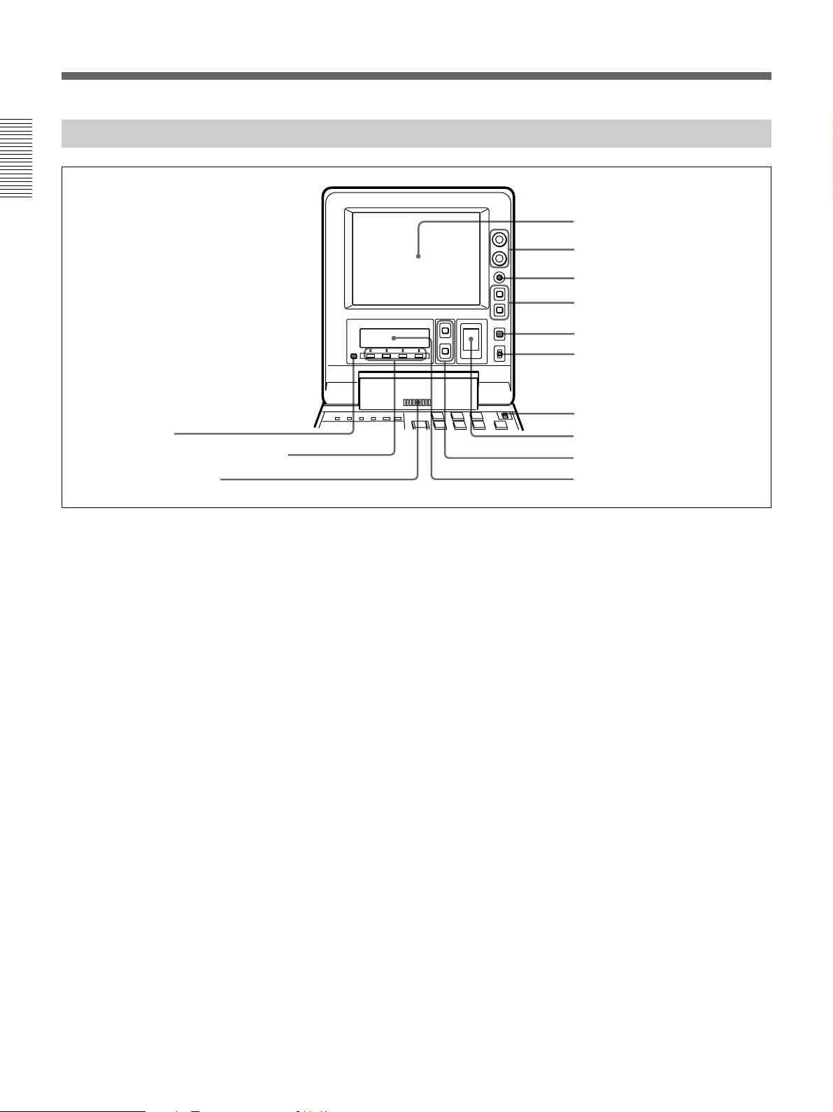
Location and Function of Parts
Display Panel
Chapter 1 Overview
!£ PAGE button
!™ Sub LCD operation buttons F1 to F4
!¡ Audio monitor speaker
1 LCD monitor
2 BRIGHT (brightness)/
CONTRAST knob
3 WARNING indicator
4 Timecode operation buttons
5 COUNTER SELECT button
6 LIGHT switch
7 METER switch
8 Audio level meter
9 UP and DOWN buttons
!º Sub LCD
1 LCD monitor
1)
Displays the playback or E-E pictures
. Time data,
status information, and setup menus, etc. are
superimposed on the LCD monitor.
2 BRIGHT (brightness)/CONTRAST knob
Adjusts the brightness and contrast of the LCD
monitor 1. Adjustments have no effect on the
recorded or output video.
3 WARNING indicator
Lights when the battery is exhausted or an error
occurs.
It flashes when the end of battery power is near.
4 Timecode operation buttons
HOLD button: Stops the progress of the timecode
generator. Press this button before setting
timecode or user bits to hold those values.
RESET button: Press this to reset the preset data of
CNT (counter value) or TC (timecode) or UB
(user bit) indication in the sub LCD !º. Resetting
the CNT value erases all edit points that have been
set.
Use this button also when resetting the setup menu
to its factory default settings.
For more information, see “Setting Time Data” on page 61.
For information about how to reset the setup menu to its
factory default settings, see the section “Resetting the menu
settings to their factory default values” page 105.
5 COUNTER SELECT button
Alternately selects CNT (counter value), TC
(timecode), and UB (user bits) as the time data used in
editing and displayed in the sub LCD !º.
6 LIGHT (backlight on/off) switch
Turns the backlights of the sub LCD !º and audio
level meter 8 on and off.
You can also use the LIGHTSW setting of the sub LCD menu
to turn the LCD monitor power on and off. For details, see
page 74.
7 METER switch
Selects the audio channel whose level is displayed by
the audio level meter 8.
CH-1/2: Display the recording, playback, and E-E
levels of audio channels 1 and 2.
CH-3/4: Display the recording, playback, and E-E
levels of audio channels 3 and 4.
.........................................................................................................................................................................................
1) E-E pictures: “E-E” stands for “Electric to Electric”. In
E-E mode, the video and audio signals that are input to
the VCR’s recording circuitry do not pass through any
magnetic conversion circuits but instead are output via
electric circuits only. The pictures output in E-E mode are
referred to as E-E pictures.
14 Chapter 1 Overview
Page 15

8 Audio level meter
Displays the recording and playback audio levels of
two (CH-1/2 or CH-3/4) of the four audio channels
(CH-1 to CH-4), as selected with the METER switch
7.
9 UP and DOWN buttons
Press to make settings in the sub LCD menu.
For more information about the sub LCD menu, see “Sub
LCD Menu Home Page and Sub LCD Operation Buttons”
on page 66.
!º Sub LCD
Displays time data, status information, remaining
battery capacity, remaining tape time, sub LCD menu,
setup menu and error messages.
For more information about the sub LCD menu, see “Sub
LCD Menu Home Page and Sub LCD Operation Buttons”
on page 66.
!¡ Audio monitor speaker
Plays the mixed audio signal of the audio channels
selected with the MONITOR item in the sub LCD
menu. Adjust the volume with the LEVEL knob on the
front control panel. You cannot monitor sound from
the speaker when headphones are connected to the
HEADPHONES jack.
Chapter 1 Overview
For more information about the MONITOR item, see page
71.
!™ Sub LCD operation buttons F1 to F4
Select items in the sub LCD menu.
For more information about the sub LCD menu, see “Sub
LCD Menu Home Page and Sub LCD Operation Buttons”
on page 66.
!£ PAGE button
Switches between pages in the sub LCD menu.
For more information about the sub LCD menu, see “Sub
LCD Menu Home Page and Sub LCD Operation Buttons”
on page 66.
Chapter 1 Overview 15
Page 16
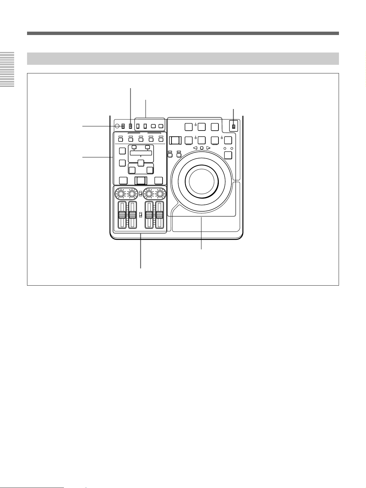
Location and Function of Parts
Control Panel
Chapter 1 Overview
REC INHI switch (tape
transport section)
Editing section
(see page 20)
REMOTE/LOCAL switch (see below)
Timecode, character and setup menu
section (see page 19)
TC CHARACTER
REC INHI
INT
EXT
AUDIO
CH1,1/2 CH2,3/4
TRIM
CLIP
LINK
ENTRY SHIFT
AUTO EDIT
AUDIO INPUT
PRESET
VARIABLE
PB
AUDIO
PRESET
VARIABLE
MENU
ON
SET
OFF
TC
PLAYER
OFF
LOCAL
REMOTE
ON
ASSEMBLE INSERT
VIDEO
AUDIO IN
–+
LIST MARK
DELETE
IN OUT
PREVIEW REVIEW
CH-1
CH-2 CH-3 CH-4
REC
PREROLL
REC SEQ EDIT
INHI
r
RECORDER
0
REVERSE
SERVO
4
)
FORWARD
EJECT REW PLAY F FWD
6
Tape transport section (see page 17)
METER switch (see “Display Panel” on page 14)
METER
CH-1/2
CH-3/4
STANDBY
STOP
p
SHUTTLE JOG
Audio control section (see page 21)
REMOTE/LOCAL switch
Selects the source for control of this unit. When two
DSR-70/70P units are connected, set this switch on the
player to REMOTE.
REMOTE: This unit is controlled from the device
connected to the REMOTE connector. In this
case, all VCR operations using this unit’s control
panel are disabled except the STOP and EJECT
buttons.
When combining two DSR-70/70P units as a pair
of recorder and player, set the REMOTE/LOCAL
switch of the player to REMOTE.
LOCAL: This unit is controlled from the control
panel. Normally set the switch to this position.
When the REMOTE is selected, you can determine which
tape transport control buttons on the control panel are
enabled. See setup menu item 006 on page 102.
16 Chapter 1 Overview
Page 17

Tape transport section
!∞ REC INHI switch
TC CHARACTER
REC INHI
OFF
LOCAL
INT
ON
REMOTE
ASSEMBLE INSERT
AUDIO IN
DELETE
PREVIEW REVIEW
!§ Cassette compartment
EXT
VIDEO
CH1,1/2 CH2,3/4
–+
TRIM
CLIP
LIST MARK
LINK
ENTRY SHIFT
IN OUT
AUTO EDIT
AUDIO INPUT
PRESET
VARIABLE
PB
AUDIO
PRESET
VARIABLE
CH-1
CH-2 CH-3 CH-4
AUDIO
1 PREROLL button
Chapter 1 Overview
2 REC INHI indicator
3 REC/SEQ button
4 EDIT button
REC
PREROLL
REC SEQ EDIT
0
REVERSE
SERVO
INHI
r
4
)
FORWARD
ON
MENU
SET
OFF
TC
EJECT REW PLAY F FWD
6
PLAYER
RECORDER
STANDBY
SHUTTLE JOG
p
STOP
METER
CH-1/2
CH-3/4
5 STOP button
6 Search button and indicators
7 STANDBY indicator
8 F FWD button
9 PLAY button
!º Jog and shuttle dials
!¡ SERVO indicator
!™ REW button
!£ PLAYER and RECORDER
buttons and indicators
!¢ EJECT button
1 PREROLL button
Press to run the tape up to the preroll point (located in
advance of the IN point by the amount of the preroll
time). You can set the preroll time using setup menu
item 001 (page 102). You can set the state of the unit
at the end of preroll by using setup menu item 401
(page 108).
By pressing this button at the same time as the IN/
OUT or AUDIO IN buttons in the editing section, you
can search for a timecode set in advance and stop at
that position. (The tape is cued up to the preset
timecode position.)
2 REC INHI (recording inhibit) indicator
Lights under the following situations.
•Set the REC INHI switch !∞ to ON.
•Set the REC/SAVE switch on the cassette to SAVE.
When the REC INHI switch !∞ is in the OFF position, then
it is possible to make the REC INHI indicator flash in this
state. For details, see setup menu item 107 on page 106.
3 REC/SEQ (recording/sequence) button
Press together with the PLAY button 9 to start
recording.
When two DSR-70/70P units are combined, this button
allows you to perform sequential recording from one
unit to another.
For details, see “Sequential Recording Using Two Units”
on page 80.
To monitor E-E mode
You can monitor input signals in E-E mode by
pressing this button from stop mode. The button lights
when pressed. To return to the original picture, press
the STOP button 5. You can view E-E video during
playback, search, fast forward, and rewind by pressing
this button.
The E-E video continues for as long as the button is
kept pressed.
Chapter 1 Overview 17
Page 18

Location and Function of Parts
4 EDIT button
Press together with the PLAY button 9 to perform
manual editing.
To monitor E-E mode
Chapter 1 Overview
You can monitor input signals in E-E mode by
pressing this button from stop mode. The button lights
when pressed, and the input signals selected with the
ASSEMBLE or INSERT buttons appear in E-E mode.
To return to the original picture, press the STOP
button 5. You can view E-E video during playback,
search, fast forward, and rewind by pressing this
button. The E-E video continues for as long as the
button is kept pressed.
5 STOP button
Press this button, lighting it, to stop playback or
recording. When you stop playback, the LCD monitor
displays E-E or still picture playback, depending on
the PB/EE setting in the sub LCD menu.
Setting setup menu item 105 to ON or LIMIT causes
this button to flash when the input video signal and the
reference video signal are asynchronous.
6 Search button and indicators
Press to enter search mode. (The JOG or SHUTTLE
indicator lights)
In shuttle mode, you can start playback at preset speed
by rotating the shuttle dial to the desired position and
pressing this button.
When setup menu item 128 is set to ON, this button
functions as a pause button. You can use the pause
button to make a pause during sequential recording
carried out using two DSR-70/70P units.
7 STANDBY indicator
Lights when the tape drum is rotating with tension
applied (standby on). It goes out when the drum stops
rotating and tension is released (standby off).
To protect the tape, the unit normally changes to
standby off when stop mode continues for longer than
8 minutes. If you operate a dial or any of the tape
transport buttons except STOP 5 while the unit is in
this state, the unit changes to standby on and enters the
mode of the button or dial that you pressed.
Press the ENTRY/SHIFT and STOP 5 buttons at the
same time to switch between standby on and standby
off manually.
8 F FWD (fast forward) button
Press this button, lighting it, to fast forward the tape.
By pressing the TRIM+/MARK button and this button
simultaneously, you can cue up to any Mark IN point
or cue point provided by ClipLink log data.
For details, see Chapter 6 “ClipLink Operation” on page
91.
9 PLAY button
Press this button, lighting it, to start playback.
Recording starts when you press this button together
with the REC/SEQ button 3, and manual editing
starts when you press this button together with the
EDIT button. If you press this button only during
recording or manual editing, recording or manual
editing stops and the unit returns to playback mode.
!º Jog and shuttle dials
To search in shuttle mode, rotate the outer ring (shuttle
dial). To search in jog mode, press the inner ring (jog
dial) until it clicks and then rotate. Rotate in the
clockwise direction to search in the forward direction
(the FORWARD indicator lights), and rotate in the
counterclockwise direction to search in the reverse
direction (the REVERSE indicator lights).
For more information about search, see “Finding Edit
Points — Search” on page 49.
!¡ SERVO indicator
Lights when the drum and capstan are servo-locked.
!™ REW (rewind) button
Press this button, lighting it, to rewind the tape.
Alternatively, by pressing the TRIM+/MARK button
and this button simultaneously, you can cue up to any
Mark IN point or cue point provided by ClipLink log
data.
For details, see Chapter 6 “ClipLink Operation” on page
91.
For more information about tape protection, see the setup
menu items in the 500s on page 108.
18 Chapter 1 Overview
Page 19
!£ PLAYER/RECORDER buttons and indicators
When two DSR-70/70P units are combined and
connected via the REMOTE (9-pin) connectors or DV
connector (when DSBK-140 is installed), press to
control one unit from another.
PLAYER button: The buttons of the editing and
tape transport sections on the recorder side of the
control panel work to control the player.
RECORDER button: The buttons of the editing and
tape transport sections on the recorder side of the
control panel work to control the recorder itself.
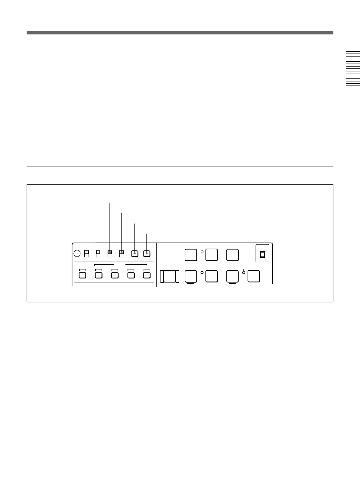
Timecode, character and setup menu section
1 TC INT/EXT switch
2 CHARACTER switch
3 MENU button
4 SET button
!¢ EJECT button
Press to eject the cassette or open the cassette
compartment !§. The button lights while the cassette is
being ejected.
Chapter 1 Overview
!∞ REC INHI switch
When on, recording to the tape is inhibited, regardless
of the setting of the cassette’s REC/SAVE switch.
(The REC INHI indicator 2 lights.)
!§ Cassette compartment
Insert a cassette here. Press the EJECT button !¢ to
open the compartment.
LOCAL
REMOTE
VIDEO
TC CHARACTER
ON
INT
OFF
EXT
AUDIO
CH1,1/2 CH2,3/4
MENU
SET
TC
REC INHI
OFF
ON
ASSEMBLE INSERT
1 TC INT/EXT (internal/external timecode)
switch
Selects the timecode to use.
INT: Use the timecode generated by this unit’s built-
in timecode generator.
EXT: The external timecode input to the TC IN
connector.
2 CHARACTER switch
Selects whether or not to display timecode and other
superimposed text data on the LCD monitor and the
output from the VIDEO OUTPUT 2 (SUPER)
connector.
REC
PREROLL
EJECT REW PLAY F FWD
6
0
REC SEQ EDIT
INHI
r
SERVO
4
)
3 MENU button
Use for setup menu operations. The setup menu
appears on the LCD monitor when you press this
button, and the original display appears when you
press it again.
For more information about setup menu operations, see
Chapter 7 “Setup Menu” on page 101.
4 SET button
Use to make setup menu settings, timecode settings,
and user bit settings.
For more information about setup menu operations, see
Chapter 7 “Setup Menu” on page 101. For more
information about timecode and user bit settings, see
“Setting Time Data” on page 61.
STANDBY
STOP
p
METER
CH-1/2
CH-3/4
Chapter 1 Overview 19
Page 20

Location and Function of Parts
Editing section
Use two DSR-70/70P units or one DSR-70/70P unit
and an editing player for editing.
Chapter 1 Overview
4 AUDIO IN button
5 ENTRY/SHIFT button
6 DELETE button
7 IN/OUT buttons
8 PREVIEW button
1 ASSEMBLE button and indicator
2 INSERT buttons and indicators
REC INHI
OFF
ON
ASSEMBLE INSERT
AUDIO IN
DELETE
PREVIEW REVIEW
TC CHARACTER
LOCAL
REMOTE
VIDEO
–+
LIST MARK
IN OUT
ON
INT
OFF
EXT
AUDIO
CH1,1/2 CH2,3/4
TRIM
CLIP
LINK
ENTRY SHIFT
AUTO EDIT
MENU
3 TRIM/CLIPLINK buttons
SET
TC
PLAYER
PREROLL
EJECT REW PLAY
6
0
REC
INHI
SERVO
REC SEQ
r
4
9 AUTO EDIT button
!º REVIEW button
1 ASSEMBLE button and indicator
Press this button, lighting the indicator, to carry out
assemble editing. Press the button again, turning the
indicator off, to leave assemble edit mode.
2 INSERT buttons and indicators
Press these buttons, turning the indicators on, to select
signals for insert editing. Press the buttons again,
turning the indicators off, to cancel the selection.
VIDEO button: Selects the video signal.
AUDIO CH1/CH-1,2 and CH2/CH-3,4 buttons:
When the AUDIO recording mode is 2 channel/48
kHz these select CH-1 (channel 1) or CH-2.
When the AUDIO recording mode is 4 channel/32
kHz, these select CH-1 and CH-2 (channels 1 and
2) or CH-3 and CH-4.
In this case it is not possible to select channels 1
to 4 individually.
TC button: Selects the timecode signal.
3 TRIM/CLIPLINK buttons
Press the +/MARK or –/LIST buttons while pressing
the IN/OUT buttons 7 or AUDIO IN button 4 to
adjust edit points in unit of 1 frame. The +/MARK
button advances 1 frame, and the –/LIST button
returns 1 frame.
By pressing the TRIM+/MARK button and the F FWD
or REW button simultaneously, you can cue up to any
Mark IN point or cue point provided by ClipLink log
data.
For details, see Chapter 6 “ClipLink Operation” on page
91.
During two-camera switched recording carried out
using the optional DSBK-180/180P board, you can
switch between the composite video signals from the
two video cameras by pressing the +/MARK button
and the –/LIST button at the same time.
20 Chapter 1 Overview
For more information about two-camera switched
recording, see the section “Two-Input Switched Video
Recording” on page 82.
Page 21
4 AUDIO IN button
In insert editing, press this button together with the
ENTRY/SHIFT button 5 to set audio IN point
separately from video IN point (audio split editing).
After setting audio IN points, you can press this button
alone to display them in the sub LCD.
7 IN/OUT (IN point/OUT point) buttons
Press these buttons, lighting them, together with the
ENTRY/SHIFT button 5 to set an IN point (edit start
point) or OUT point (end point). After setting edit
points, you can press either of these buttons alone to
display the IN or OUT point in the sub LCD.
Chapter 1 Overview
5 ENTRY/SHIFT button
Press together with the IN button, the OUT button, or
the AUDIO IN button to set edit points. The buttons
for the edit points that you set light.
Pressing this button together with a button with two
functions, such as the REC/SEQ button, selects the
function indicated in orange on the button.
6 DELETE button
Press together with the IN/OUT buttons 7 or the
AUDIO IN button 4 to delete edit points. The buttons
go out or flash. A flashing button indicates that the edit
point needs to be set again.
The DELETE button flashes to indicate contradictions
that will prevent previews and automatic editing, for
example when the durations are different on the player
and recorder, or when the IN and OUT points are equal
or reversed. In this case, set the edit points again.
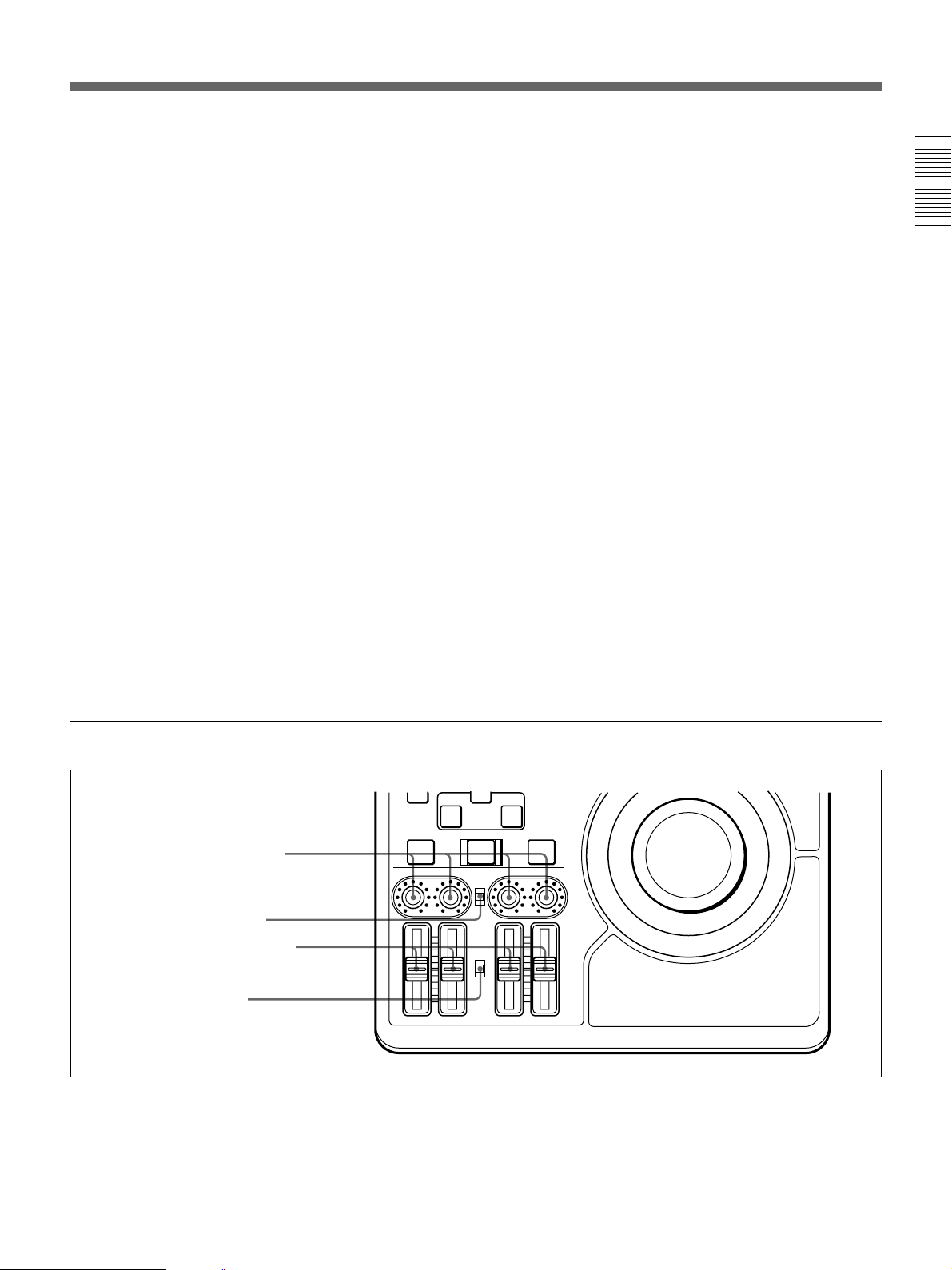
Audio control section
8 PREVIEW button
Press this button, lighting it, when you want to preview
editing results on the monitor after setting edit points
but before executing an edit. If an IN point has not
been set, the point where you press this button is used
as the IN point in the preview. This button lights
during the preview and goes out when the preview
finishes.
9 AUTO EDIT button
After setting edit points, press this button, lighting it to
execute an automatic edit (record to the recorder). If an
IN point has not been set, the point where you press
this button is used as the IN point in the automatic edit.
This button lights during execution and goes out when
execution finishes.
!º REVIEW button
After executing an automatic edit, press this button,
lighting it to review the results of the edit.
PREVIEW REVIEW
1 AUDIO INPUT CH-1 to CH-4
level adjustment knobs
2 AUDIO INPUT PRESET/
VARIABLE switch
3 PB AUDIO CH-1 to CH-4 level
adjustment sliders
4 PB AUDIO PRESET/
VARIABLE switch
CH-1
1 AUDIO INPUT CH-1 to CH-4 level adjustment
knobs
Adjust the levels for each channel of analog audio
signals input to the AUDIO INPUT CH-1/CH-2
connectors on the rear panel, or of the audio signals
input to the SDI, SDTI(QSDI), and DV IN/OUT
connectors of the optional boards.
IN OUT
AUTO EDIT
AUDIO INPUT
PRESET
VARIABLE
PB
AUDIO
PRESET
VARIABLE
CH-2 CH-3 CH-4
2 AUDIO INPUT PRESET/VARIABLE switch
Select the adjustment function for the levels of analog
audio signals input to the AUDIO INPUT CH-1/CH-2
connectors on the rear panel, or of the audio signals
input to the SDI, SDTI(QSDI), and DV IN/OUT
connectors of the optional boards.
Chapter 1 Overview 21
Page 22

Location and Function of Parts
PRESET: Preset to fixed levels. Levels cannot be
adjusted with the level adjustment knobs.
VARIABLE: Levels adjustable with level
adjustment knobs. This allows you to adjust the
Chapter 1 Overview
levels while viewing the audio level meters in E-E
mode.
For more information about switching to E-E mode, see the
descriptions of the REC/SEQ and EDIT buttons (pages 17
and 18)
Front Control Section
3 PB AUDIO CH-1 to CH-4 level adjustment
sliders
Make level adjustments by channel for playback audio
channels 1 to 4.
4 PB AUDIO PRESET/VARIABLE switch
Selects the level adjustment function for playback
audio.
PRESET: Preset to fixed levels. Levels cannot be
adjusted with the level adjustment sliders.
VARIABLE: Levels adjustable with the level
adjustment sliders. This allows you to adjust the
levels while viewing the audio level meter.
1 VIDEO knob
2 CHROMA knob
3 SET UP/BLACK LEVEL knob
4 CHROMA PHASE knob
5 POWER indicator
8 POWER switch
1 VIDEO knob
Adjusts the video signal output level. This knob is a
push switch. When you press it to bring it into the
raised position, the setting becomes VARIABLE.
When you press it again to depress it, the setting
returns to PRESET.
PRESET: This is the normal setting. Regardless of
the knob position, the video signal output level is
set to the standard value.
VARIABLE: The video signal output level can be
adjusted across a range of ±3 dB.
You can change the adjustment range by using setup menu
item 714. For details, see page 110.
6 LEVEL knob
7 HEADPHONES jack
2 CHROMA knob
Adjusts the chroma signal output level. This knob is a
push switch. When you press it to bring it into the
raised position, the setting becomes VARIABLE.
When you press it again to depress it, the setting
returns to PRESET.
PRESET: This is the normal setting. Regardless of
the knob position, the chroma signal output level
is set to the standard value.
VARIABLE: The chroma signal output level can be
adjusted across a range of ±3 dB.
You can change the adjustment range by using setup menu
item 714. For details, see page 110.
22 Chapter 1 Overview
Page 23

3 SET UP/BLACK LEVEL knob
Adjusts the setup level (for DSR-70) or the black level
(for DSR-70P). This knob is a push switch. When you
press it to bring it into the raised position, the setting
becomes VARIABLE. When you press it again to
depress it, the setting returns to PRESET.
PRESET: This is the normal setting. Regardless of
the knob position, the setup level (for DSR-70) or
the black level (for DSR-70P) is set to the
standard value.
VARIABLE: The setup level can be adjusted across
a range of ±30 IRE (for DSR-70) and the black
level can be adjusted across a range of ±210 mV
(for DSR-70P).
4 CHROMA PHASE knob
Adjusts the chroma phase (phase relative to burst).
This knob is a push switch. When you press it to bring
it into the raised position, the setting becomes
VARIABLE. When you press it again to depress it, the
setting returns to PRESET.
PRESET: This is the normal setting. Regardless of
the knob position, the chroma phase is set to the
standard value.
VARIABLE: The chroma phase can be adjusted
across a range of ±30˚.
5 POWER indicator
Lights green when the POWER switch 8 is turned on,
and changes to red when recording starts.
6 LEVEL (speaker/headphones level) knob
Adjusts the volume of the speaker or headphones
connected to the HEADPHONES jack 7.
7 HEADPHONES jack (stereo phone jack)
Connect headphones. The speaker is muted when
headphones are connected.
8 POWER switch
Powers the unit on and off. When the unit is powered,
the POWER indicator 5 lights.
Chapter 1 Overview
Top Panel
Slide the cover off while pressing the lever.
3 Shoulder belt attachment
fixture
1 Battery connector
Connect a BP-L60/L60A//L90/L90A Battery Pack,
DC-L90 Battery Adaptor, or AC-DN2/DN2A AC
Adaptor.
When the AC-550/550CE AC Adaptor or another
power supply has been connected to the DC IN
connector on the rear panel, the power from the DC IN
connector is used instead of the power from this
connector.
2 BREAKER button
1 Battery connector
For more information, see “Power Preparations” on page
29.
Note
The AC-DN1 AC Adaptor and the BP-L40 and NP-1B
Battery Packs cannot be used.
Chapter 1 Overview 23
Page 24
Location and Function of Parts
2 BREAKER button
When excess power flows inside the unit, the breaker
activates to protect the circuits by automatically
shutting down the power. After inspecting and
adjusting the unit, press this button. If there is no
Chapter 1 Overview
further trouble, the power will be restored.
For inspection and adjustment of the unit, consult your Sony
dealer.
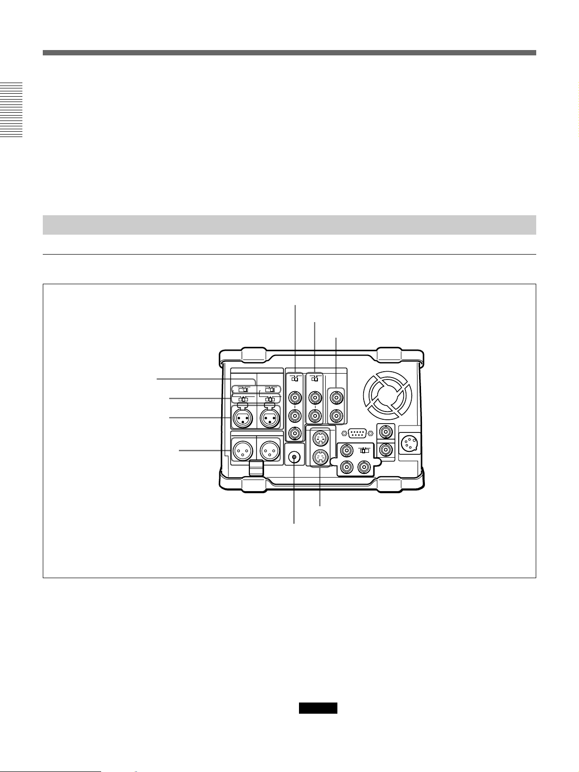
Rear Panel
Analog audio/video input and output section
1 48V ON/OFF switches
2 AUDIO INPUT CH-1/CH-2
level switches
3 AUDIO INPUT CH-1/CH-2
connectors
4 AUDIO OUTPUT CH-1/3 and
CH-2/4 connectors
AUDIO INPUT VIDEO
0
-60 +4dbu
CH-1 CH-2
AUDIO OUTPUT
1/3 2/4
0
-60 +4dbu
75Ω 75Ω
MONITOR
3 Shoulder belt attachment fixture
Attach the supplied shoulder belt.
For more information, see “Using the Shoulder Belt” page
126.
5 REF. VIDEO IN/OUT connectors and 75Ω termination switch
6 VIDEO INPUT connectors and 75Ω termination switch
7 VIDEO OUTPUT 1 and 2 (SUPER) connectors
ONOFF
ONOFF
REF. INPUT
IN
OUT
AUDIO
IN
OUT
S VIDEO
OUTPUT
1
2(SUPER)
REMOTE
Y
R-Y B-Y
DC IN
TC IN
OUTIN
TC OUT
This illustration shows the DSR-70/70P fitted with the optional DSBK-170.
1 48V ON/OFF switches
When the AUDIO INPUT CH-1/CH-2 level switches
are set to –60 dBu, setting these switches to ON causes
48-V power to be supplied to the AUDIO INPUT
connectors.
2 AUDIO INPUT CH-1/CH-2 level switches
Select the input level of the analog audio signals of
input channels 1 and 2.
24 Chapter 1 Overview
8 S VIDEO IN/OUT connectors
9 MONITOR AUDIO connector
–60 dBu: Microphone input
0 dBu: Line audio input
+4 dBu: Line audio input (0 dBu = 0.775 Vrms)
For microphone inputs, use 48-V microphones, and set
the AUDIO INPUT CH-1/CH-2 level switches 2 to
–60 dBu and the 48V ON/OFF switches 1 to ON,
respectively.
Caution
Using a microphone other than a 48-V microphone
may damage the microphone.
Page 25

3 AUDIO INPUT CH-1/CH-2 connectors (XLR 3pin, female)
Input the analog audio signals of input channels 1 and
2.
4 AUDIO OUTPUT CH-1/3 and CH-2/4
connectors (XLR 3-pin, male)
Output the audio signals of the channels selected with
the LINE OUT in the sub LCD menu. You can select
two combinations of output signals: channels 1 and 2,
or channels 3 and 4.
For more information about LINE OUT settings, see page
71.
Note
The level can be adjusted from the control panel, but
mixed signals cannot be output.
5 REF. VIDEO IN/OUT (reference video signal
input/output) connectors (BNC type) and 75Ω
termination switch
When using an external reference video signal, input it
to one of the REF. VIDEO IN connectors. Set the 75Ω
termination switch to OFF when the signal is bridged,
and to ON when the signal is not bridged.
The REF. VIDEO OUT connector outputs a reference
video signal.
8 S VIDEO IN/OUT connectors (4-pin)
Input an S-video signal with separated Y (luminance)
and C (chroma: 3.58 MHz for DSR-70 and 4.43 MHz
for DSR-70P) components to the S VIDEO IN
connector.
The S VIDEO OUT connector outputs an S-video
signal.
9 MONITOR AUDIO connector (phono jack)
Output the audio signals of the channels selected with
the MONITOR in the sub LCD menu. The level is
adjustable, and mixing is possible.
For more information about the MONITOR item, see page
71.
Chapter 1 Overview
6 VIDEO INPUT (analog composite video input)
connectors (BNC type) and 75Ω termination switch
Input an analog composite video signal. Set the 75Ω
termination switch to OFF when the signal is bridged,
and to ON when the signal is not bridged.
7 VIDEO OUTPUT (analog composite video
output) 1 and 2 (SUPER) connectors (BNC type)
Output analog composite video signals. When the
CHARACTER switch is set to ON, timecode, menu
settings, error messages and other information is
superimposed on the output of 2 (SUPER) connector.
For details about the superimposed information, see page
61.
Chapter 1 Overview 25
Page 26

Location and Function of Parts
Optional board/timecode/remote control/power input and output section
Chapter 1 Overview
AUDIO INPUT VIDEO
0
-60 +4dbu
CH-1 CH-2
AUDIO OUTPUT
1/3 2/4
0
-60 +4dbu
75Ω 75Ω
MONITOR
AUDIO
ONOFF
REF. INPUT
IN
OUT
S VIDEO
IN
OUT
ONOFF
OUTPUT
1
2(SUPER)
Cable clamp
1 REMOTE (9-pin remote control) connector
(D-sub 9-pin)
When editing with two DSR-70/70P units, connect this
connector on each unit using a 9-pin remote control
cable (not supplied). When editing with this unit and
external equipment, connect the external equipment.
2 TC IN (timecode input) connector (BNC type)
To record timecode from an external device, input the
timecode from the external device’s timecode output
connector.
1 REMOTE connector
REMOTE
Y
R-Y B-Y
DC IN
TC IN
OUTIN
TC OUT
2 TC IN connector
3 DC IN connector
4 TC OUT connector
5 Optional interface board fitting
a)
port
a) This illustration shows the DSR-70/70P fitted with the optional DSBK-170.
4 TC OUT (timecode output) connector
(BNC type)
Outputs the following types of timecode, depending on
the VCR operating status.
During playback: The playback timecode
During recording: The timecode generated by the
internal timecode generator, or the timecode input
through the TC IN connector.
For details of the timecode output during recording, see
setup menu item 611 (page 109).
3 DC IN (external power input) connector (XLR
4-pin, male)
To power this unit with AC power, connect to the DC
output connector of the AC-550/550CE AC adaptor.
You can also connect a BP-90/90A Battery Pack using
the DC-210 Battery Adaptor.
Power supplied through this connector is used on a
priority basis even when you have connected a battery
pack or AC-DN2/DN2A AC Adaptor to the battery
connector on the top panel.
For more information, see “Power Preparations” on page
29.
26 Chapter 1 Overview
5 Optional interface board fitting port
Install any one of the following optional interface
boards here:
•DSBK-140 i.LINK/DV Input/Output Board
•DSBK-150 SDTI (QSDI) Input/Output Board
•DSBK-160 SDI Input/Output Board
•DSBK-170 Analog Component Input/Output Board
The connectors provided by the optional boards are as
follows.
Page 27

Connector of the DSBK-140
Connectors of the DSBK-170
DV IN/OUT
DV IN/OUT (DV input/output) connector (6-
pin IEEE1394 connector): This connector is i.LINK
compatible. Connect to another DSR-70/70P unit
or a consumer DV camera to carry out such
operations as recording and editing.
Connectors of the DSBK-150
SDTI(QSDI)
IN
SDTI(QSDI)
OUT
SDTI(QSDI) IN/OUT (input/output) connectors
(BNC type): Use to input/output digital video/audio
signals in SDTI(QSDI) format.
Y
R-Y B-Y
OUTIN
IN/OUT switch
Y, R–Y, B–Y (luminance and color difference
signal) input/output connectors (BNC type): Use to
input or output analog component signals (Y,
R–Y, B–Y). When using as input connectors, set
the IN/OUT switch to IN. When using as output
connectors, set the IN/OUT switch to OUT.
Chapter 1 Overview
Connectors of the DSBK-160
SDI IN
12
SDI OUT
SDI IN/OUT 1, 2 (serial digital interface signal
input, output 1, 2) connectors (BNC type): Use to
input/output digital video/audio signals in SDI
(D1) format.
Chapter 1 Overview 27
Page 28

Page 29
Power Preparations and Connections
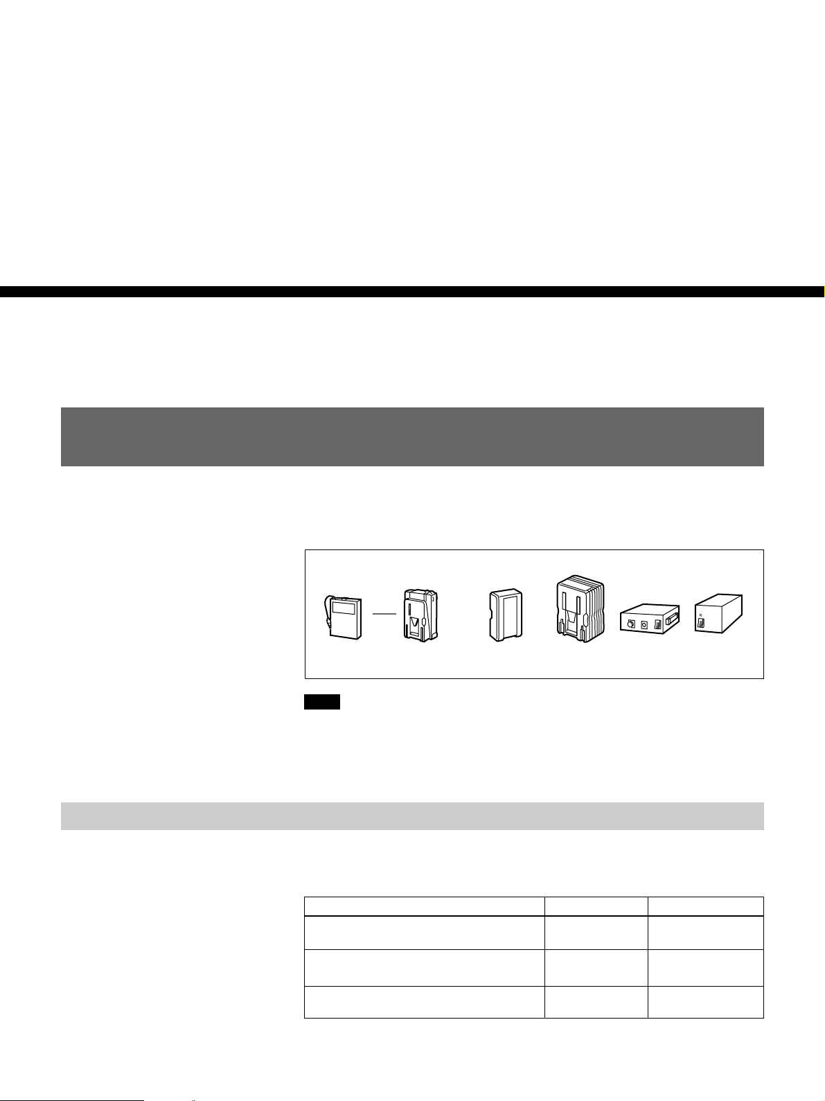
Power Preparations
This unit can be powered by batteries or AC power.
Example battery packs and AC adaptors that can be used are shown below.
Chapter2
Chapter 2 Power Preparations and Connections
Usable Batteries
Battery pack Battery
BP-90A DC-L90
Note
If you attach or remove batteries or AC adaptors incorrectly, they may fall
down and cause body injury.
Follow the procedures described below to attach or remove them.
Batteries that can be used with this unit are as follows. For each type of
battery, a special battery adaptor and battery charger is required.
Battery Battery Adaptor Battery Charger
BP-90/90A (mounted on this unit) DC-L90 BC-210/210CE/
BP-90/90A (connected to DC IN
connector)
BP-L60/L60A/L90/L90A Not needed BC-L100/L100CE/
adapter
Battery pack AC adaptor
BP-L60/BP-L60A/
BP-L90/BP-L90A
AC-DN2A AC-550/
550CE
410/410CE
DC-210 BC-210/210CE/
410/410CE
L50
CMA-8A/
8ACE
In the subsequent pages, the batteries such as the BP-90/90A and BP-L60/
L60A will also be referred to as the BP-90(A) and BP-L60(A).
Chapter 2 Power Preparations and Connections 29
Page 30

Power Preparations
Notes about battery usage
•Before using the batteries, be sure to charge them fully with the special
battery charger. Refer to the operating instructions of your battery charger
for more information about how to charge the batteries.
•Batteries may not be completely charged if you charge them immediately
after use when they are still warm. You should wait until the batteries
cool before charging them.
Using the BP-L60(A)/L90(A) Battery Pack
Chapter 2 Power Preparations and Connections
To attach the battery pack
This unit can be operated for about 120 minutes at normal temperature on
fully charged BP-L90 Battery Pack. (When no optional board is installed.)
To charge the battery pack
Before use, charge the battery pack with the BC-L100/L100CE Battery
Charger. It takes about 2.5 hours to charge the BP-L60(A) and about 3.5
hours to charge the BP-L90(A).
For more information about how to charge the battery pack, refer to the manual
for the BC-L100/L100CE.
Attach the BP-L60(A)/L90(A) as shown in the following figure. Before
attaching, remove the cover of the battery connector.
Remove the cover in the same way that you remove the battery pack. For details
see the next section “To remove the battery pack”.
1Align the groove on the top panel of
the BP-L60(A)/L90(A) with the
guides.
2Slide the BP-L60(A)/L90(A) in so
that its connector is firmly
connected to the unit’s battery
connector.
30 Chapter 2 Power Preparations and Connections
Page 31

To remove the battery pack
With the lever pushed in, slide the BP-L60(A)/L90(A) out.
BP-L60(A)/L90(A)
Using the BP-90(A) Battery Pack
Different battery adaptors are used when mounting the BP-90(A) on the
top panel of this unit and when connecting it the DC IN connector.
This unit can be operated for about 70 minutes at normal temperature on a
fully charged BP-90(A) Battery Pack. (When no optional board is
installed.)
To charge the battery pack
Before use, be sure to charge the battery pack with the BC-210/210CE/
410/410CE Battery Charger. It takes about 2 hours to charge the BP90(A).
For more information about how to charge the battery pack, refer to the manual
for the BC-210/210CE/410/410CE.
To attach to the top panel of this unit
Lever
Chapter 2 Power Preparations and Connections
Use the DC-L90 Battery Adaptor.
1 Mount the BP-90(A) in the DC-L90.
1 Lift the lever up.
2 Open the side cover.
Chapter 2 Power Preparations and Connections 31
3 Insert the BP-90(A).
4 Push the plug in.
5 Close the side cover and
pull the lever down.
(Continued)
Page 32

Power Preparations
2 Attach the DC-L90 to the top panel of this unit.
Use the same method that you use to attach the BP-L60(A)/L90(A).
For details, see “To attach the battery pack” on page 30.
To connect to the DC IN connector
Use the DC-210 Battery Adaptor.
Chapter 2 Power Preparations and Connections
For more information about connections, refer to the operating instructions of the
DC-210.
You can also connect another battery pack to the DC IN connector when a
BP-90(A) battery pack is already mounted on the top panel of this unit.
When you connect an external battery pack to the DC IN connector, the
power supply automatically switches to the external battery pack from an
internal battery pack mounted on the top panel of the unit.
Notes
•Noise may occur in video and audio signals at the moment when the unit
switches from the internal to the external battery.
•It is always the external battery connected to the DC IN connector that
serves as power supply. You cannot switch the power supply from the
external battery to the internal battery while the external battery is
connected to the DC IN connector.
When an external battery pack is almost exhausted
If an internal battery pack is already mounted, disconnect the external
battery pack by pulling its DC power cord out from the DC IN connector.
If no internal battery back is mounted, disconnect the external battery pack
after mounting a fully charged internal battery pack.
When an internal battery pack is almost exhausted
For the remaining battery power indication (see page 66), the “BATT”
display flashes.
Connect a fully charged external battery pack to the DC IN connector, then
exchange the internal battery pack.
Using AC Power
You can operate the unit from an AC power source by using the AC-550/
550CE AC Adaptor or AC-DN2/DN2A (subsequently also refered to as
the AC-DN2(A)) AC Adaptor.
Use the AC-550/550CE to connect the AC power source to the DC IN
connector, and the AC-DN2(A) to connect the AC power source to the
battery connector.
32 Chapter 2 Power Preparations and Connections
Page 33

To use the AC-550/550CE
As shown in the following figure, connect the AC-550/550CE to the AC
power source and turn it on.
When you connect AC power, the power supply automatically switches to
the AC power from a battery pack mounted on the top panel of the unit.
Note
Noise may occur in video and audio signals at the moment when the unit
switches from the battery pack to AC power.
Chapter 2 Power Preparations and Connections
POWER switch: ON
AC-550/550CE
To AC power
To use the AC-DN2(A)
DC IN
DC power cord (supplied with AC-550/550CE)
DC OUT
AC power cord
(supplied with AC-550/550CE)
Follow the procedure below to mount the AC-DN2(A) on the top panel of
this unit, and connect to AC power.
When two DSR-70/70P units are combined, you can supply both units
with power by fitting a single AC-DN2A to either unit.
Caution
When you use a single AC-DN2A to supply power to two DSR-70/70P
units, exercise the following caution:
•Do not turn the POWER switches of both units on at a time. (Turn one
unit on, then wait a moment before turning the other unit on.)
•Do not insert cassettes into both units at a time. (Insert a cassette into one
unit, then wait a moment before inserting a cassette into the other unit.)
If you turn on the POWER switches of the recorder and player at a time or
insert cassettes to the recorder and player at a time, this unit possibly may
not be powered. In this case, turn the POWER switches of both units off,
then turn them on again following the above instructions. Should this unit
not be powered, turn both POWER switches off and disconnect the AC
power cord of the AC-DN2A. After about 10 minutes, connect the AC
power cord of the AC-DN2A again and turn the two units’ POWER
switches on one by one as mentioned above.
Chapter 2 Power Preparations and Connections 33
Page 34

Power Preparations
Chapter 2 Power Preparations and Connections
1 Remove the cover of the battery connector.
2 Insert the V-wedge shoe on the AC-DN2A in the V-groove on one unit
and slide the AC-DN2A until the battery charging connector is
connected to the battery connector.
Battery charging
connector
Battery connector
3 Use the DC power cord (supplied with the AC-DN2A) to connect the
DC output connector on the AC-DN2A and the DC IN connector on
the rear of another unit.
To DC output connector
DC IN
DC power cord
(supplied with the AC-DN2A)
4 Supply the AC-DN2A with AC power.
34 Chapter 2 Power Preparations and Connections
For information about how to supply AC power to the AC-DN2A, refer to the
manual for the AC-DN2A.
Page 35

System Configuration
The figure below shows example equipment that can be connected to this
unit.
DVCAM camcorder
DV camcorder
DV camcorder
DSR-70/70P
DVCAM cassette
DV cassette
i.LINK
(DSBK-140)
i.LINK
(DSBK-140)
a)
a)
Microphone
DSR-70/70P
(This unit)
b)
Headphones
SDI(DSBK-160)
SDTI(QSDI)
(DSBK-150)
SDTI(QSDI)
(DSBK-150)
Component
(DSBK-170)
a)
Chapter 2 Power Preparations and Connections
DNW-A25/A25P digital VCR
a)
a)
DSR-60/60P/80/80P/85/85P
a)
digital VCR
ES-7 EditStation
Battery packs,
AC adaptors
a) The DSBK-140/150/160/170 is an optional board.
b) Caution
Using a microphone other than a 48-V microphone
may damage the microphone.
Video monitor
Audio monitor System
Analog Betacam VCR
Chapter 2 Power Preparations and Connections 35
Page 36

Connections for Cut Editing Using Two DSR-70/
Power Preparations
70P Units — i.LINK Connections (Optional DSBK-140
Required)
For a cut editing system using two DSR-70/70P units with an i.LINK
interface, the following figure shows an example of the connections.
Use the same configuration when dubbing signals in DVCAM format via
an i LINK interface.
Note
In this case, both of the recorder and player require the DSBK-140 i.LINK/
DV Input/Output Board.
Chapter 2 Power Preparations and Connections
DSR-70/70P (recorder)
DSR-70/70P (player)
DV IN/OUT DV IN/OUT
1
1 6-pin to 6-pin i.LINK/DV cable (supplied with the DSBK-140)
DSR-70/70P (recorder and player) settings
Switch/menu Recorder Player
REMOTE/LOCAL LOCAL REMOTE
Sub LCD menu general
setting item REMOTE
Sub LCD menu home
page input video/audio
signal indication
i.LINK i.LINK
i.LINK Other than i.LINK
It is possible to combine two DSR-70/70P units using the optional BKNW225 Docking Kit (see page 125).
Also, for ease of carriage of the unit, you can use a shoulder belt (see page
126).
For more example editing system connections, see Chapter 8“Connections and
Settings” (page 113).
36 Chapter 2 Power Preparations and Connections
Page 37

Editing
Sequence of Editing Operations
The following is a typical sequence of cut editing operations carried out
using two DSR-70/70P units as a pair of player and recorder.
Sequence of Operations See
Making necessary settings
Chapter3
Chapter 3 Editing
“Settings for Editing” (page 38)
Insert cassettes.
• Insert a cassette for recording the
results of editing in the recorder.
• Insert the cassette on which
material to be edited has been
recorded in the player.
Select an edit mode.
Determine edit points.
• Preview edit results.
• Modify edit points, if necessary.
Execute an edit.
• Review the edit results.
• Redo the edit, if necessary.
“DVCAM cassettes” (page 43)
“Selecting an Edit Mode”
(page 47)
• “Finding Edit Points
—Search” (page 49)
• “Setting Edit Points” (page
50)
“Executing an Edit” (page 57)
Chapter 3 Editing 37
Page 38

Settings for Editing
Settings for Editing
Recorder Settings
When using two units of the DSR-70/70P as a pair of recorder and player
in an editing system, set the recorder and player as follows. Basically, the
same recorder settings and player settings apply when you use a DSR 70/
70P unit as a stand-alone recorder or player.
Make settings as follows.
POWER indicator
Chapter 3 Editing
Sub LCD
6
5
1
LOCAL
REMOTE
4
TC
EXT
INT
3
UP/DOWN buttons
7
2
1 Set the REMOTE/LOCAL switch to LOCAL.
2 Set the POWER switch to ON, then make the following checks.
When the unit is powered, the POWER indicator lights and the sub
LCD home page appears in the sub LCD.
38 Chapter 3 Editing
Check Indication/What to do
Enough
battery
power
remaining?
No
condensation
in the unit?
Check the remaining battery power indication.
If “BATT” is flashing
Replace the battery.
If “HUMID!” is displayed
Leaving the unit powered, wait until the message
disappears.
(In this case, the alarm message “MOISTURE
HAS BEEN DETECTED” also appears on the
LCD monitor.)
See for details
“ 5Remaining
battery power
indication” (page
67)
“Condensation”
(page 127)
Page 39

3 Use the COUNTER SELECT button to select the type of time data to
be used.
Each press of the button cycles through three options in the sub LCD:
CNT, TC, and UB.
Selectable time data Time data indication in the sub LCD
Count in the counter CNT
Timecode TC
User bit data UB
4 When the time data selected in step 3 is timecode (TC), use the TC
INT/EXT switch to select the type of timecode.
Selectable timecode TC INT/EXT switch setting
Timecode generated by the internal
timecode generator
External timecode input to the TC IN
connector
INT
EXT
5 Select the formats of video and audio input signals to be used.
If any signal not connected to the unit is selected, the corresponding
signal indication in the sub LCD flashes.
Chapter 3 Editing
To select an input video signal format
Press the sub LCD operation button F4, highlighting the input video
signal indication, then press the UP button or the DOWN button
repeatedly until the input video signal indication corresponding to the
desired video signal appears in the sub LCD.
Selectable video signals
(Input connectors)
Composite signals (VIDEO INPUT)
S-video signal (S VIDEO IN)
i.LINK (DV) signals (DV IN/OUT
(optional DSBK-140))
SDTI (QSDI) signals (SDTI(QSDI) IN
(optional DSBK-150))
SDI signals (SDI IN (optional DSBK-
160))
Component signals (Y, R–Y, B–Y
(optional DSBK-170))
a) When using the component signals (CMPNT), set the IN/OUT switch of
the DSBK-170 to IN.
Input video signal indication in the
sub LCD
CMPST
S VIDEO
i.LINK
SDTI
SDI
CMPNT
a)
Selecting the i.LINK (DV) or SDTI (QSDI) signals for input video
causes the same to be automatically selected also for input audio.
(Continued)
Chapter 3 Editing 39
Page 40

Settings for Editing
To select an input audio signal format
Press the sub LCD operation button F3, highlighting the input audio
signal indication, then press the UP button or the DOWN button
repeatedly until the input audio signal indication corresponding to the
desired audio signal appears in the sub LCD.
Chapter 3 Editing
Selectable audio signals
(Input connectors)
Analog signals (AUDIO INPUT CH-1/
CH-2)
i.LINK (DV) signals (DV IN/OUT
(optional DSBK-140))
SDTI (QSDI) signals (SDTI(QSDI) IN
(optional DSBK-150))
SDI signals (SDI IN (optional
DSBK-160))
Input audio signal indication in the
sub LCD
ANALOG
i.LINK
SDTI
SDI
Selecting the i.LINK (DV) or SDTI (QSDI) signals for input audio
causes the same to be automatically selected also for input video.
Cut editing using i.LINK
When using a cut editing system as illustrated in the section
“Connections for Cut Editing Using Two DSR-70/70P Units
— i.LINK connections” on page 36, select “i.LINK” for input video
and audio.
6 Select the audio recording mode.
Press the sub LCD operation button F2, highlighting the audio
recording mode indication, then press the UP button or the DOWN
button so that the audio recording mode indication corresponding to
the selected mode appears in the sub LCD.
40 Chapter 3 Editing
Selectable audio recording mode Indication in the sub LCD
Two-channel, 48-kHz recording mode
Four-channel, 32-kHz recording mode
Notes
2/48k
4/32k
•In the DVCAM format, there are two audio recording modes, that is,
two channel, 48-kHz mode and four-channel, 32-kHz mode. It is not
possible to select other modes (for example, four-channel, 48-kHz
mode).
•If an audio signal in a different mode than the base tape is used in
assemble or insert editing, the signals will be discontinuous at the edit
points and correct editing will not be obtained. For this reason, audio
editing between different modes is inhibited on this unit.
For smooth editing operations, check the audio recording mode of the
base tape beforehand. If on a tape there is a point where the audio
mode is switched, you cannot perform an insert editing on that point.
•Once you have started recording, you cannot change the audio mode
selection.
Page 41

7 Use the AUDIO INPUT PRESET/VARIABLE switch and the AUDIO
INPUT CH 1 to CH-4 level adjustment knobs to adjust the audio input
levels.
Watching the audio level meter, adjust the levels so that the meter does
not indicate higher values than 0 dB when the audio signals are at their
maximum.
Player Settings
AUDIO INPUT PRESET/
VARIABLE switch setting
PRESET
VARIABLE
Make settings as follows.
POWER indicator
1
LOCAL
Audio input level adjustment
Preset to fixed levels. Levels cannot be adjusted
with the level adjustment knobs.
Levels adjustable with the level adjustment
knobs. Adjust the levels while viewing the audio
level meter in E-E mode.
Chapter 3 Editing
REMOTE
2
1 Set the REMOTE/LOCAL switch to REMOTE.
(Continued)
Chapter 3 Editing 41
Page 42

Settings for Editing
2 Set the POWER switch to ON, then make the following checks.
When the unit is powered, the POWER indicator lights and the sub
LCD home page appears in the sub LCD.
Chapter 3 Editing
Check Indication/What to do
Enough
battery
power
remaining?
No
condensation
in the unit?
Check the remaining battery power indication.
If “BATT” is flashing
Replace the battery.
If “HUMID!” is displayed
Leaving the unit powered, wait until the
message disappears.
(In this case, the alarm message
“MOISTURE HAS BEEN DETECTED” also
appears on the LCD monitor.)
See for details
“
5
Remaining
battery power
indication”
(page 67)
“Condensation”
(page 127)
42 Chapter 3 Editing
Page 43

Handling Cassettes
This unit can use standard-size and mini-size DVCAM cassettes listed
below.
Model name Size
PDV-64ME/94ME/124ME/184ME Standard size
PDVM-12ME/22ME/32ME/40ME Mini size
The numbers in each model name indicate the maximum recording/
playback time (in minutes) for each model. For example, the PDV-184ME
has a maximum recording/playback time of 184 minutes.
Notes
•If you insert an incorrect type of cassette, it will be automatically ejected.
•When operating this unit as a player, you can also use DV cassettes on
the unit. However, it is the best choice to always use DVCAM cassettes
because they are more reliable than DV cassettes whatever your purpose
may be: playback, editing, or long-period storage of recordings.
•Cassettes that have been recorded by a DV-format recorder can be played
back on this unit, but you cannot use them to carry out recording by
editing. If you insert such a cassette into this unit, the NO EDIT
indication lights up in the sub LCD menu home page.
Chapter 3 Editing
DVCAM cassettes
The following figure illustrates the DVCAM cassette’s appearance.
Standard size
Mini size
REC/SAVE switch
For details of this switch, see
“Preventing accidental erasure”
(page 44).
Cassette memory
This memory is used to store ClipLink
log data. For details of ClipLink log data,
refer to “ClipLink Guide” supplied with
this unit.
Chapter 3 Editing 43
Page 44

Handling Casettes
Notes on using cassettes
Chapter 3 Editing
•Before storing the cassette, rewind the tape to the beginning and be sure
to put the cassette in its storage case, preferably on end instead of flat on
its side. The storage case of a DVCAM cassette is specially designed to
ensure a long-period storage of the tape.
Storing a cassette in any other condition (not rewound, out of its case,
etc.) may cause the video and audio contents to become damaged over
time.
•If the cassette memory connector (contact point) becomes dirty,
connection problems may occur and cause a loss of functions. Remove
away any dust or dirt from this area before using the cassette.
•If the cassette is dropped on the floor or otherwise receives a hard impact,
the tape may become slackened and may not record and/or play back
correctly.
For instructions on removing tape slack, see below.
Preventing accidental erasure
Checking the tape for slack
Set the REC/SAVE switch on the cassette to SAVE to prevent accidental
erasure of recorded contents.
REC/SAVE switch
Set to SAVE.
REC
SAVE
To enable re-recording
Set the cassette’s REC/SAVE switch to REC.
If you insert a cassette into the unit when this switch is set to SAVE, the
unit will not record when you press the PLAY button while holding down
the REC/SEQ button.
Using a paper clip or a similar object, turn the reel gently in the direction
shown by the arrow. If the reel does not move, there is no slack. Insert the
cassette into the cassette compartment, and after about 10 seconds take it
out.
44 Chapter 3 Editing
Page 45

Loading/Ejecting Cassettes
1
2
3
EJECT REW PLAY F FWD
SERVO
)
0p
6
4
STOP
STANDBY
Paper clip, etc.
Reel
To load a cassette
Chapter 3 Editing
LCD indicator
STANDBY indicator
1 With the unit powered on, press the EJECT button.
The control panel lifts up and the cassette compartment opens.
2 Load a cassette in the direction shown in the figure.
The message “CASSETTE OUT” displayed on the LCD monitor
changes to “TAPE UNTHREAD”.
Note
If the message on the LCD monitor does not change to “TAPE
UNTHREAD”, redo the cassette insertion procedure.
3 Close the control panel. (You should hear a click.)
The STANDBY indicator lights.
Chapter 3 Editing 45
Page 46

Handling Casettes
To eject the cassette
1
2
1 With the unit powered on, press the EJECT button.
The control panel lifts up and the cassette compartment opens.
Chapter 3 Editing
2 Remove the cassette and close the control panel.
Notes
•Do not shut the display panel while the control panel is still open. Doing
so may damage the lock mechanism of the display panel.
•The EJECT cannot be used to eject a cassette when battery power falls to
below about 9 V. Connect an external power supply.
For information about the remaining battery power, see the section “5
Remaining battery power display” on page 67.
46 Chapter 3 Editing
Page 47

Selecting an Edit Mode
When you use two DSR-70/70P units, you can do two types of editing:
assemble editing and insert editing. This section provides an outline of
each type and explains how to select an edit mode.
In the subsequent explanation of editing operations in this chapter,
illustrations of a pair of DSR-70/70P units (player and recorder) combined
using the optional BKNW-225 Docking Kit are used (see page 125). In
each illustration, as viewed from the front, the unit on the left is the player
and the unit on the right is the recorder.
Assemble Editing
In assemble editing, you record video and audio materials in order from
the start of the tape. In addition to video and audio, timecode is also
recorded. If timecode is already recorded on the tape, the new timecode is
recorded so as to form a continuous sequence with the existing timecode.
Assemble editing is convenient when you are recording on a new tape.
Chapter 3 Editing
Selecting assemble mode
Note
Before you begin assemble editing for the first time with a new tape, video
signal such as black signal and timecode must be recorded on the tape in
advance of the recorder IN point for a length equal to or greater than the
preroll time.
ASSEMBLE
2
RECORDER
1
1 Press the RECORDER button on the recorder control panel.
The RECORDER indicator lights.
2 Press the ASSEMBLE button on the recorder control panel.
The ASSEMBLE indicator lights.
To cancel assemble mode
Press the ASSEMBLE button again to turn the ASSEMBLE indicator
off.
Chapter 3 Editing 47
Page 48

Selecting an Edit Mode
Insert Editing
Selecting insert mode
Chapter 3 Editing
In insert editing, you insert video, audio, and timecode at desired positions
on an already recorded tape. You can insert all three types of data at the
same time, or insert one of the types separately.
Note
Before you use an unrecorded tape in insert editing, video signal such as
black signal and timecode must be recorded on all over the tape.
RECORDER
1
VIDEO
INSERT
AUDIO
TC
2
CH1,1/2 CH2,3/4
1 Press the RECORDER button on the recorder control panel.
The RECORDER indicator lights.
2 Press one or more of the INSERT buttons on the recorder control panel
to select the signals you want to insert.
The corresponding INSERT indicators light.
To cancel insert mode
Press the lit INSERT buttons again to turn the corresponding indicators
off. Selection of a signal is canceled when its indicator goes out.
48 Chapter 3 Editing
Page 49

Finding Edit Points —Search
Playback in search mode using the jog and shuttle dials allows finding edit
points quickly.
Jog mode
Playback speed is determined by the rotation speed of the jog dial between
±1 times normal speed. Rotate the dial in the clockwise direction to search
in the forward direction, and rotate the dial in the counterclockwise
direction to search in the reverse direction.
Shuttle mode
Playback speed is determined by the rotation angle of the shuttle dial
between ±32 times normal speed (21 steps). Click points allow playback
at ±5 times normal speed.
Rotate the dial in the clockwise direction to search in the forward
direction, and rotate the dial in the counterclockwise direction to search in
the reverse direction.
Switching between each mode
Lighting the JOG or SHUTTLE indicator shows the corresponding mode
is selected.
Switching from jog to shuttle mode
Rotate the shuttle dial.
Switching from shuttle to jog mode
Press the jog dial or rotate the jog dial while setting the shuttle dial at still
position.
To switch between normal playback and search modes
Press the PLAY and search buttons alternately.
As factory default setting, rotating the jog or shuttle dial switches to search
mode at any time except during recording and editing.
If you change the setting of setup menu item 101, the above function will
be disabled and switching to search mode will be possible only when the
search button is pressed.
Chapter 3 Editing
For details about setting, see item 101 on page 106.
Chapter 3 Editing 49
Page 50

Selecting an Edit Mode
Setting Edit Points
Setting Edit Points
Chapter 3 Editing
In editing operations, there are four edit points: an IN point and an OUT
point on the recorder side, and an IN point and an OUT point on the player
side. As soon as you set three of the edit points, the fourth edit point is
calculated automatically.
In insert editing, you can set IN points for audio separately from the IN
points for video (audio split editing).
For details, see “To set audio IN points separately from video IN points (audio
split editing)” on page 51.
Note
If it is necessary to operate the buttons or dial on the player, set setup
menu item 006 “LOCAL FUNCTION ENABLE” to ENA beforehand (see
page 102).
Proceed as follows to set edit points.
1
3
AUDIO IN
–+
TRIM
CLIP
LIST MARK
DELETE
PREVIEW REVIEW
LINK
ENTRY SHIFT
IN OUT
AUTO EDIT
2
AUDIO IN
–+
TRIM
CLIP
LIST MARK
DELETE
PREVIEW REVIEW
PREVIEW button
LINK
ENTRY SHIFT
IN OUT
AUTO EDIT
AUTO EDIT button
1 Rotate the player side jog or shuttle dial to find the player edit points.
For details about jog/shuttle dial operations, see “Finding Edit Points
— Search” on page 49.
50 Chapter 3 Editing
Page 51

2 Press the IN button together with the ENTRY/SHIFT button at the
point you want to set as the IN point. Press the OUT button together
with the ENTRY/SHIFT button at the point you want to set as the
OUT point.
The IN and OUT points are set, and the IN and OUT buttons light.
3 Repeat steps 1 and 2 on the recorder side to set the recorder IN or
OUT point.
As soon as you set three edit points on the player and recorder, the
PREVIEW button and the AUTO EDIT button light to indicate that
you can conduct a preview or edit.
Note
If you set four or more edit points on the player and recorder, the
DELETE button flashes. You cannot conduct an edit when the unit is
in this state. Delete the unneeded edit points.
For details, see “Modifying Edit Points” on page 55.
To set audio IN points separately from video IN points (audio split editing)
Chapter 3 Editing
In insert editing, press the AUDIO IN button together with the ENTRY/
SHIFT button at the point you want to set as the audio IN point.
The audio IN point is set and the AUDIO IN button lights.
Chapter 3 Editing 51
Page 52

Selecting an Edit Mode
Setting Edit Points
Checking Edit Points
To display the time data of edit points
Chapter 3 Editing
You can check the time data of edit points and the duration between two
edit points by displaying them in the sub LCD.
Press the recorder side or player side IN or OUT button.
While the button remains pressed, the time data for the corresponding edit
point is displayed in the sub LCD.
To display the duration between two edit points
From among the recorder side and player side IN buttons (or AUDIO IN
buttons) and OUT buttons, press two of the buttons together.
The duration appears in the sub LCD while the buttons are kept pressed.
In some cases, negative durations preceded by a minus sign (–) may be
displayed.
The displayed durations are calculated as follows.
When two edit points are set: The duration between the two edit points
When only one edit point is set: The duration between the edit point and
the current tape position
When no edit points are set: The duration of the most recently set edit
points
AUDIO IN
–+
TRIM
CLIP
LIST MARK
DELETE
LINK
ENTRY SHIFT
IN OUT
IN button
OUT button
52 Chapter 3 Editing
Page 53

Cuing Up Edit Points
To cue up an edit point
You can cue up any edit point, or cue up a position located a specified
amount of time before the edit start point (preroll).
To set the preroll time
Using the setup menu item 001, specify how many seconds (the preroll
time) in advance of the edit start point to set the preroll point.
The factory default preroll time is 5 seconds.
For details, see page 102.
Use the following procedures to cue up an edit point or preroll the tape.
Press and hold the recorder side or player side IN or OUT button, and
press the recorder or player PREROLL button while holding the IN or
OUT button.
REC
PREROLL
AUDIO IN
–+
TRIM
CLIP
LIST MARK
DELETE
LINK
ENTRY SHIFT
IN OUT
PREROLL button
OUT button
IN button
INHI
Chapter 3 Editing
The tape runs to the IN point or OUT point and stops.
Chapter 3 Editing 53
Page 54

Selecting an Edit Mode
Setting Edit Points
To preroll the tape
Chapter 3 Editing
Press the recorder side or player side PREROLL button.
REC
PREROLL
INHI
PREROLL button
The tape runs to the preroll point, located in advance of the edit start point
by the specified amount of time, and then stops.
Previewing Edit Results
When you finish setting the edit points, the PREVIEW button flashes to
indicate that you can conduct a preview.
To conduct a preview, press the recorder side PREVIEW button, turning it
on.
STANDBY
STOP
p
STOP button
PREVIEW
PREVIEW button
During the preview, you can see the video in the recorder side LCD
monitor and listen to the audio through the recorder side speaker. The
figure below shows the video and audio signals which can be monitored.
54 Chapter 3 Editing
OUT point
Recorder unit’s
playback signals
Recorder unit’s
playback signals
IN point
Player unit’s E-E
signals
After the preview, modify, delete, or reset edit points as required.
For more information about modifying edit points, see “Modifying Edit Points”
on page 55.
Page 55

Modifying Edit Points
To delete an edit point
To stop a preview
Press the STOP button on the recorder.
The tape stops when the button was pressed.
Once you set edit points, you can delete them or modify them as required
in units of one frame.
When edit points have been set incorrectly, for example when an OUT
point is located before an IN point or when the durations of editing
segments on the player and recorder do no match, the DELETE buttons
flash to alert you that a preview or edit cannot be conducted. Correct the
edit points as required.
To turn a flashing DELETE button off without deleting an edit
point
Press the DELETE button.
Proceed as follows.
Chapter 3 Editing
AUDIO IN
–+
TRIM
CLIP
LIST MARK
DELETE
LINK
ENTRY SHIFT
IN OUT
DELETE button
OUT button
IN button
Press the flashing DELETE button together with the IN button or the OUT
button.
The DELETE button stops flashing, and the edit point is deleted.
Chapter 3 Editing 55
Page 56

Selecting an Edit Mode
Setting Edit Points
To modify edit points slightly
Chapter 3 Editing
Proceed as follows.
AUDIO IN
DELETE
–+
TRIM
CLIP
LIST MARK
LINK
ENTRY SHIFT
IN OUT
TRIM+/MARK and
–/LIST buttons
OUT button
IN button
1 While pressing the recorder side or player side IN or OUT button,
depending on the edit point that you want to modify, press a TRIM
button (+/MARK or –/LIST) on the same side of the control panel.
The edit point time data is displayed.
Each time you press the +/MARK button, you advance one frame, and
each time you press the –/LIST button you return one frame.
2 After making the modifications, press the IN or OUT button that you
pressed in step 1.
Setting Edit Points Using the Recorder Only
If you press the PLAYER button to light the PLAYER indicator on the
control panel, you can operate the player or an external VCR with the
recorder side buttons, and set edit points.
In this case, it is recommended that you set setup menu item 006 “LOCAL
FUNCTION ENABLE” to ST&EJ (default setting) on the player
beforehand (see page 102).
56 Chapter 3 Editing
Page 57

Executing an Edit
Outline of Editing Operations
The figure below shows how the recorder and player operate during edit.
Preroll point
Recorder
a)
Preroll
IN point
Assemble editing
Tape transport
OUT point
Postroll point
Postroll
b)
Monitoring signals during an edit
Just as during a preview, you can see the video in the recorder side LCD
monitor and listen to the audio through the recorder side speaker.
The figure below shows the video and audio signals which can be
monitored.
Playback
Player
Time flow
a) The factory default preroll time is 5 seconds. You can use the setup menu item
001 to set a time from 0 to 30 seconds (see page 102).
b) The postroll time is set to 2 seconds.
Insert editing
Playback
Stop
Stop
Over
recording
Chapter 3 Editing
IN point OUT point
Recorder’s
playback signals
Player’s E-E signals
Recorder’s
playback signals
Note
For insert editing, the tape set on the recorder must be a recorded one. You
cannot perform insert editing on a blank tape.
Chapter 3 Editing 57
Page 58

Executing an Edit
Executing an Edit
Starting an Edit
Chapter 3 Editing
To start an edit, press the AUTO EDIT button.
AUDIO IN
–+
TRIM
CLIP
LIST MARK
DELETE
PREVIEW REVIEW
LINK
ENTRY SHIFT
IN OUT
AUTO EDIT
ENTRY/SHIFT button
OUT button
REVIEW button
AUTO EDIT button
The AUTO EDIT button is lit during an edit. It goes out when the edit
finishes.
To stop an edit
Press the ENTRY/SHIFT button together with the OUT button.
The edit ends, and the point where you pressed the buttons becomes the
OUT point.
To abort an edit
Press the STOP button on the recorder.
To review the edit results
Press the REVIEW button.
When the review ends, the tape returns to the OUT point and stops.
58 Chapter 3 Editing
Page 59

Redoing an Edit
Edit point data is retained even after you execute an edit, until you set new
edit points.
You can redo an edit after modifying the edit point data.
AUDIO IN
–+
TRIM
CLIP
LIST MARK
LINK
DELETE
PREVIEW REVIEW
ENTRY SHIFT
IN OUT
AUTO EDIT
1
2
3
Chapter 3 Editing
1 Press the recorder side DELETE button together with the ENTRY/
SHIFT button.
2 Modify the edit points.
See “To Modify edit points slightly” (page 56) for the procedure.
3 Press the AUTO EDIT button.
Chapter 3 Editing 59
Page 60

Page 61

Setting Time Data
Chapter4
Time Data and Sub LCD Menu
This unit provides the following timecode functions:
•Setting, displaying, recording, and playing back
timecode and user bit values
•Outputting the timecode read from the tape as an
analog timecode (LTC) signal during normal-speed
playback
•Inputting an external analog timecode (LTC) signal
Information Displayed on the
LCD Monitor
The LCD monitor displays setup menus, error
messages, alarm messages, time data, and information
about the unit’s operating status.
For more information about the setup menus, see Chapter 7
“Setup Menu” (page 101).
To adjust the screen
To display superimposed text information
To display superimposed time data and text
information about the operating status of the unit in the
LCD monitor, set the CHARACTER switch to ON
(see page 19). The setup menu and error messages are
displayed regardless of the setting of the
CHARACTER switch.
When the CHARACTER switch is set to ON, the text
information is also superimposed on the output of the
VIDEO OUTPUT 2 (SUPER) connector .
To adjust the displayed text
You can adjust the position, size, and type of
superimposed information using setup menu items
002, 003, 009, and 011.
For details, see pages 102 and 103.
Chapter 4 Time Data and Sub LCD Menu
Use the BRIGHT and CONTRAST knobs to adjust the
brightness and contrast of the LCD monitor screen.
To make the backlight brighter, set the BACKLGT in
the sub LCD menu to HIGH (see page 74).
Chapter 4 Time Data and Sub LCD Menu 61
Page 62

Setting Time Data
Information displayed
The figure below shows the time data and operation
status that can be superimposed.
1 Time data type
Time data
2 Timecode reader drop-
frame mark
TCR 23 : 59 . 40 . 18
PSHUTTLESTILL
5 Operating mode
4 Recorder/player selection
a) This character can appear on the DSR-70 only. The
character to appear in these two columns is always a colon
(:) on the DSR-70P.
Note
a)
3 Timecode
generator dropframe mark
The example above shows the factory default
configuration.
Chapter 4 Time Data and Sub LCD Menu
You can use setup menu item 005 to display a different
type of time data in the second line as well.
2 Timecode reader drop-frame mark (for DSR-70
only)
. Drop frame mode (factory default setting)
: Non-drop frame mode
3 Timecode generator drop-frame mark
(for DSR-70 only)
. Drop frame mode (factory default setting)
a)
: Non-drop frame mode
4 Recorder/player selection
The indication changes depending on the status of the
RECORDER/PLAYER indicators.
No display: When the RECORDER and PLAYER
indicators are both not lit.
P: The PLAYER indicator is lit.
R: The RECORDER indicator is lit.
For details, see page 102.
1 Time data type
Display Meaning
CNT Count value of the time counter (COUNTER)
TCR Timecode reader timecode data
UBR Timecode reader user bits data
TCG Timecode generator timecode data
UBG Timecode generator user bits data
IN IN point time data
OUT OUT point time data
AI Audio IN point time data
DUR The duration between any two of the three edit
T*R Time code data from time code reader. The
U*R User bit data from the time code reader. The
points (IN, OUT, AUDIO IN)
asterisk indicates an interpolation by the time
code reader to make up for the time code data
not correctly read from the tape.
asterisk indicates that last data is retained by
the time code reader, as the new data has not
been read correctly from the tape.
62 Chapter 4 Time Data and Sub LCD Menu
Page 63

5 Operating mode
The ■ mark, indicating an auto editing segment, may
appear at the rightmost position.
The contents displayed other than the ■ mark are
listed below.
Display Operating Mode
CASSETTE OUT No cassette loaded
TAPE UNTHREAD Tape not yet threaded
STANDBY OFF Standby off mode
T. RELEASE Tension release mode
STOP Stop mode
F. FWD Fast forward mode
REW Rewind mode
PREROLL Preroll mode
PLAY Playback mode (servo unlock)
PLAY LOCK Playback mode (servo lock)
REC Recording mode (servo unlock)
REC LOCK Recording mode (servo lock)
SEQ-REC Sequential recording mode
(servo unlock)
SEQ-REC LOCK Sequential recording mode
(servo lock)
EDIT Editing mode (servo unlock)
EDIT LOCK Editing mode (servo lock)
JOG STILL Jog mode still playback
JOG FWD Forward jog
JOG REV Reverse jog
SHUTTLE +2.0 Shuttle mode (playback speed)
PREVIEW Preview mode
AUTO EDIT Auto edit mode
REVIEW Review mode
a) “+2.0” in the left box is an example of playback speed
indication.
Setting an Initial Value and Recording Timecode
Set the switches and sub LCD menu items as shown
below.
LOCAL
REMOTE
TC INT/EXT: INT
Sub LCD menu settings
Item Setting
F-RUN/R-RUN Desired setting
DF/NDF Desired setting
(general settings page) (for DSR-70)
To set an initial timecode value
Perform the following procedure.
a)
2
RESET button
1
3,5
TC CHARACTER
ON
INT
OFF
EXT
MENU SET
Chapter 4 Time Data and Sub LCD Menu
3,4,5,6 7
1 Press the COUNTER SELECT button and select
TC.
(Continued)
Chapter 4 Time Data and Sub LCD Menu 63
Page 64

Setting Time Data
2 Press the HOLD button.
The first digit of the time data
(hours:minutes:seconds:frames) in the sub LCD
begins to flash.
To set all digits to 0
Press the RESET button.
3 Confirm the JOG indicator lights, and select jog
mode if not. (Shuttle mode is not recommendable.)
4 Select the digit to set by rotating the jog dial.
The flashing digit changes to the digit on the right
when you rotate the jog dial clockwise, and to the
digit on the left when you rotate it
counterclockwise.
5 Set the value for the flashing digit by rotating the
jog dial while pressing the search button.
6 Repeat steps 4 and 5 until you finish setting all
digits.
Chapter 4 Time Data and Sub LCD Menu
7 Press the SET button.
If the F-RUN/R-RUN item is set to F-RUN, the
timecode starts to advance immediately.
To set timecode to the current time
To set user bits
You can record up to 8 hexadecimal digits of
information (date, time, event number, etc.) in the
timecode track.
Proceed as follows.
1
1 Press the COUNTER SELECT button and select
UB.
2 Carry out steps 2 to 7 of “To set an initial
timecode value”.
Settings are made in hexadecimal (0, 1, 2,... 8, 9,
A, B,... E, F).
1 Set the F-RUN/R-RUN item to F-RUN and the
DF/NDF in the sub LCD menu to DF (for DSR-70)
(see page 73).
2 Carry out steps 1 to 6 of “To set an initial
timecode value” (on previous page) to set the
timecode to a time slightly ahead of the current
time.
3 Press the SET button at the instant when the
current time matches the displayed timecode.
64 Chapter 4 Time Data and Sub LCD Menu
Page 65

Synchronizing the Internal Timecode Generator With an External Signal — External Lock
You can synchronize the internal timecode generator
of this unit by inputting an external timecode signal
(LTC).
To synchronize to an external timecode
signal
Connect the external timecode (LTC) signal to the TC
IN connector, and set the TC INT/EXT switch to the
EXT position.
This starts the synchronization of the internal timecode
generator to the external timecode signal. Once the
synchronization is achieved, the internal timecode
generator continues to be synchronized even when the
external timecode signal is disconnected.
Note
When the input mode is SDTI or i.LINK (the SDTI or
i.LINK indicator is present in the subsidiary LCD),
then setting the TC INT/EXT switch to the EXT
position automatically synchronizes the internal
timecode generator to the timecode transferred through
the SDTI (DSBK-150) or i.LINK (DSBK-140)
interface.
Chapter 4 Time Data and Sub LCD Menu
Note that when the TC INT/EXT switch is set to EXT,
the advance mode and frame count mode (DSR-70
only) are automatically set as follows.
Advance mode: free running
Frame count mode (DSR-70 only): the same as the
external timecode signal (drop frame or non-drop
frame)
Checking the synchronization to the
external signal
Press the STOP button to stop this unit, then press the
REC/SEQ button.
Watch the time counter display, and check that the
values displayed coincide with the external timecode
values.
Chapter 4 Time Data and Sub LCD Menu 65
Page 66

Sub LCD Menu Display and Settings –– Making
Operating Mode and Video/Audio Signal Settings
The sub LCD menu displayed in the sub LCD allows
you to make operating mode and video/audio signal
settings for the unit.
Sub LCD Menu Home Page and Sub LCD Operation Buttons
The home page of the sub LCD menu is displayed
when you power the unit on.
1 Time data indication
2 Audio mode indication
3 CLIPLINK indication
4 Remaining tape time indication
5 Remaining battery power indication
Time data
display area
PAGE
Chapter 4 Time Data and Sub LCD Menu
PAGE button
Sub LCD operation
buttons F1 to F4
6 NO EDIT indication
1 Time data indication
Shows the type of time data being displayed.
TC: Timecode
UB: User bits
CNT: Counter count
2 Audio mode indication
This shows the mode in which audio is recorded.
2/48k: two-channel, 48 kHz mode
4/32k: four-channel, 32 kHz mode
– – : recording mode cannot be determined
TC 2/48k CL 184 BATT
NO
EDIT
00 : 35 : 09 : 04
AU-1 2/48k ANALOG CMPST
F1 F2 F3 F4
8 Audio recording mode indication
7 Audio setting page selection indication
3 CLIPLINK indication
These show whether or not cassette memory is present
and whether there is CLIPLINK log data.
4 Remaining tape time indication
Displays the remaining tape time (in 2-minute
increments).
When the remaining time falls to 2 minutes or less, the
indication becomes 0 and flashes.
When a tape recorded in DV format (SP mode) is
played back, indication “SP” appears.
UP
DOWN
!º Input video signal indication
9 Input audio signal indication
UP/DOWN buttons
CM: appears when there is cassette memory
CL: appears when the cassette memory includes
CLIPLINK log data.
No indication: when there is no cassette memory
–: No cassette is loaded.
66 Chapter 4 Time Data and Sub LCD Menu
Page 67

5 Remaining battery power display
Displays the remaining battery power on a scale of
seven levels. When the power is nearly exhausted, the
BATT display flashes. When the power is completely
exhausted, a flashing E (End) appears.
Regarding the remaining battery power indication, also see
the sections “3 BAT-END (battery end) setting” and “4
BAT-NE (battery near end) setting” on page 74.
6 NO EDIT indication
Appears when a tape recorded in DV format is played
back.
You may play back a tape recorded in DV format, but
you cannot record the results of editing on the tape.
This indication appears also when the audio recording
mode set on the unit is different from the audio
recording mode used on the tape.
9 Input audio signal indication
When changing the input audio signal selection, use F3
to highlight this indication, then press the UP button or
the DOWN button repeatedly so that the indication for
the desired signal appears in the sub LCD.
When none of the optional DSBK-140, DSBK-150 and
DSBK-160 boards is installed in the unit, ANALOG
is always selected.
ANALOG: Analog signals
i.LINK: i.LINK(DV) signals (DSBK-140)
SDTI: SDTI(QSDI) signals (DSBK-150)
SDI: SDI signals (DSBK-160)
If a signal not connected to the unit is selected, the
indication flashes.
Pressing F3 to highlight this indication, then pressing
the PAGE button displays the general settings page (1)
(see page 73).
7 Audio settings page selection indication
To select one of the groups of the audio settings pages
(AU-1 to AU-4) or MIX/SWP, press F1 to highlight
this display, then press the UP or DOWN button. The
selected page in the group or the audio settings sub
page appears when you press the PAGE button.
For details, see the next section, “To switch between menu
pages” on the next page.
8 Audio recording mode indication
When changing the audio recording mode selection,
use F2 to highlight this indication, then press the UP
button or the DOWN button so that the indication for
the desired mode appears in the sub LCD.
2/48k: Two-channel, 48-kHz mode
4/32k: Four-channel, 32-kHz mode
Pressing first F2 to highlight this indication, then the
PAGE button displays the general settings page (1)
(see page 73).
!º Input video signal indication
You can select CMPST (composite) or SDI as the
input video signal by pressing F4 to highlight this
display and then pressing the UP or DOWN button.
CMPST: Composite signal
SDI: SDI signal
S VIDEO: S-video signal
i.LINK: i.LINK (DV) signal (DSBK-140)
CMPNT: Component signal (DSBK-170)
SDTI: SDTI (QSDI) signal (DSBK-150)
If you press the PAGE button after highlighting this
display, the video settings page appears, allowing you
to make advanced video settings.
For details, see the section, “To switch between menu
pages” on the next page.
Note
Selecting the i.LINK or SDTI (QSDI) signals for input
audio causes the same to be automatically selected also
for input video.
Selecting the i.LINK or SDTI (QSDI) signals for input
video causes the same to be automatically selected also
for input audio.
Chapter 4 Time Data and Sub LCD Menu
Chapter 4 Time Data and Sub LCD Menu 67
Page 68

Sub LCD Menu Display and Settings – Making Operating Mode and Video/Audio Signal Settings
Sub LCD Menu Basic Operations
To switch between menu pages
In addition to the home page, the sub LCD menu has
pages that allow you to make settings for input and
output of video and audio signals, and other general
settings.
You can switch between pages by pressing the buttons
shown in the figure below.
F1 F2 F3 F4
AU-1
PAGE
Chapter 4 Time Data and Sub LCD Menu
UP
AU-2
PAGE
For more information about the video and audio settings
pages, see the section “Input and Output Settings for Video
and Audio Signals” on page 70.
Home page
a)
01 : 23 : 45 : 01
AU-1
2/48k
F1 F2 F3 F4
ANALOG CMPST
General settings (1)
PAGE PAGE
Video
PAGE
b)
PAGE
Audio 1-1
PAGE
b)
Audio 2-1
Audio 1-2
PAGE
b)
Audio 1-3
PAGE
Home
68 Chapter 4 Time Data and Sub LCD Menu
MIX/
SWP
IN
OUT
General settings (2)
PAGE
F4
Home
PAGE
Home
a) When the unit is first powered on, and when you
return to the home page, none of the items on the
page are highlighted.
b) You can return to the home page by keeping the
PAGE button pressed for more than one second.
Page 69

To select an item
Display the page that contains the item you want to
select, then press F1 to F4, that is located in the same
column as the item.
The selected item is highlighted.
Press the button repeatedly until the item that you want
to select is highlighted.
To change a setting
With the item that you want to change highlighted,
press the UP or DOWN button repeatedly until the
item is set to the value that you want.
Chapter 4 Time Data and Sub LCD Menu
Chapter 4 Time Data and Sub LCD Menu 69
Page 70

Input and Output Settings for Video and Audio Signals –– Sub LCD Menu
Using the sub LCD menu, you can make settings
related to the input and output of video and audio
signals.
For more information about basic sub LCD menu
operations, see section “Sub LCD Menu Basic Operations
(see page 68)”.
Making Settings in the Audio Settings Pages
For audio settings, use the audio settings pages of the
sub LCD menu.
The audio settings pages are divided into four groups,
AU-1 to AU-4. Using these four groups of audio
settings pages, you can make four different sets of
audio settings. To call up one of the settings pages in a
group, select the group from the home page.
Each settings page has a number that indicates its
group and its position within the group. For example,
audio settings page 1-1 is the first page in group AU-1.
Chapter 4 Time Data and Sub LCD Menu
Audio settings page 1-1
[AU-1-1]
AGC
OFF
Item Setting
AGC Turn the audio input AGC circuits ON and
OFF (enabled when the AUDIO INPUT
PRESET/VARIABLE switch of the control
panel is set to PRESET).
LIMITER Turn the audio input limiter circuits ON and
OFF (enabled when the AUDIO INPUT
PRESET/VARIABLE switch of the control
panel is set to VARIABLE).
LIMITER
OFF
Display when the optional DSBK-140/150/
160 board is installed
CH
1*IN-1
IN-2
IN-3
IN-4
2 IN-1
*IN-2
IN-3
IN-4
MIX/SWAP
3 IN-1
IN-2
*IN-3
IN-4
[AU-1-2]
4 IN-1
IN-2
IN-3
*IN-4
Display when the optional DSBK-140/150/
160 board is not installed
CH
1*IN-1
IN-2
2 IN-1
*IN-2
MIX/SWAP
3*IN-1
IN-2
Item Setting
MIX/SWAP CH 1 to 4 Select up to two audio input
signals (IN-1 to IN-4) to be
assigned to channels 1 to 4. When
two signals are selected, they are
mixed.
To select
1 Select the desired channel using
operation buttons F1 to F4.
2 Press the same operation button
as used in 1 repeatedly until the
input signal indication (IN-1/IN2/IN-3/IN-4) corresponding to
the desired signal is
highlighted.
3 With the input signal indication
for the selected signal
highlighted, press either the UP
button or the DOWN button so
that an asterisk (*) is added to
the highlighted input signal
indication.
4 To select the second input signal
for the same channel, repeat
steps 2 and 3.
To cancel the selection
Proceed as above to highlight the
desired input signal indication,
then press either the UP button or
the DOWN button so that the
asterisk preceding the highlighted
input signal indication disappears.
[AU-1-2]
4 IN-1
*IN-2
To switch to audio settings page 1-2
Press the PAGE button.
Audio settings page 1-2
Audio settings page 1-2 displayed differs between
when the optional DSBK-140/150/160 board is
installed and when it is not installed.
70 Chapter 4 Time Data and Sub LCD Menu
Note
When analog audio (ANALOG)
has been selected for input,
selecting IN-3 or IN-4 as the audio
input signal results in mute audio.
To switch to audio settings page 1-3
Press the PAGE button.
Page 71

Audio settings page 1-3
3 Press the PAGE button.
LINE OUT
CH-1/2
Item Setting
LINE OUT Select channels 1/2 or 3/4 as the line
MONI.VR Select ENA for an output level
MONITOR Select the monitor audio output signal.
MONI.VR MONITOR
ENA METER
out channels.
determined according to the setting of
the PB AUDIO PRESET/VARIABLE
switch of the control panel, or DIS for
a fixed output level.
• Select METER to linking the monitor
audio output selection to the setting
of the METER switch for the display
panel. Either channels 1 and 2
mixed or channels 3 and 4 mixed will
be output.
• When not linking the monitor audio
output selection to the setting of the
METER switch, select the desired
channel (CH-1/CH-2/CH-3/CH-4).
[AU-1-3]
An audio settings subpage (input mixing page)
appears as shown below.
TC 2/48k CL 184 BATT
NO
00 : 35 : 09 : 04
EDIT
MIX OFF 1+2m1 1+2m2 IN /OUT
PAGE
F1 F2 F3 F4
To switch pages
Press the F4 button.
An output monitor settings page like the one below
appears.
TCCL2/48k 184 BATT
NO
EDIT
00 : 35 : 09 : 04
1 2 1+2 IN/ OUT
PAGE
F1 F2 F3 F4
Chapter 4 Time Data and Sub LCD Menu
Audio settings pages 2-1 to 4-3
Make settings in the same way as pages AU-2 to AU-
4.
Making Settings in the Audio Settings Subpages
Use the audio settings subpages to make mix and swap
input and output settings for channels 1 and 2.
To display the audio settings subpages
1 Press F1 to highlight the audio settings item in the
home page.
2 If the item displayed is not “MIX/SWP”, press the
UP button until “MIX/SWP” appears.
Each press of the F4 button switches between the input
mixing settings page and the output monitor settings
page.
To return to the home page
Press the PAGE button.
Contents of the audio settings subpages
When you change the settings of the audio settings
subpages, the settings of the AU-1 page change as
well, and vice versa.
However, when there is no item in the subpages
corresponding to a setting made in the AU-1 page, the
setting is not reflected in the subpages.
Chapter 4 Time Data and Sub LCD Menu 71
Page 72

Input and Output Settings for Video and Audio Signals –– Sub LCD Menu
Input mixing settings page
By pressing F1 to F3, you can make the following
three settings for mixing of input signals in audio
channels 1 and 2. The selected setting is highlighted.
To select input signals, use audio settings page 1-2.
MIX OFF: Assign IN-1 to channel 1, and assign IN-
2 to channel 2.
1+2 → 1: Assign mixed signals of IN-1 and IN-2 to
channel 1, and assign IN-2 to channel 2.
1+2 → 2: Assign IN-1 to channel 1, and assign mixed
signals of IN-1 and IN-2 to channel 2.
Output monitor settings page
By pressing F1 to F3, you can make the following
three settings for monitor output signals. The selected
setting is highlighted.
1: Assign channel 1 to monitor output.
2: Assign channel 2 to monitor output.
1+2: Assign mixed signals from channels 1 and 2 to
monitor output. (This corresponds to the
MONITOR item setting “METER” in audio
settings page 1-3.)
Chapter 4 Time Data and Sub LCD Menu
Making Settings in the Video Settings Pages
The following tables show the items that can be set in
the video settings pages.
Video settings page
MONITOR
OUTPUT
PROCESS
CONTROL
PANEL
PP MODE
OFF
WIDE
AUTO
PP SIZE
1/9
ZEBRA
OFF
PP POSI.
4
Item Setting
a)
MONITOR
When composite video (CMPST) has been
selected for input, select the E-E signal for
output to the LCD monitor of the unit.
INPUT: Input video E-E with no digital
process delay is output.
OUTPUT: Output video E-E with a digital
process delay is output
PP
MODE
Select how to display two input pictures on
a)
the LCD monitor.
OFF: Not displaying two pictures.
1: Picture-in-picture display
2: Two pictures reduced and displayed side
by side
3: Side-by-side display reduced in horizontal
direction only
a)
PP SIZE
Select the size of the smaller picture to be
inset for picture-in-picture display on the LCD
monitor.
1
1/16:
1/9: 1/9 the normal size
1/4: 1/4 the normal size
PP POSI.
a)
Select the position of the smaller picture to
be inset for picture-in picture display on the
LCD monitor.
1: Upper left position
2: Upper right position
3: Lower left position
4: Lower right position
PROCESS
CONTROL
Select what to use to control the following
items: SETUP (when using the setup menu)
or PANEL (when using the front control
section).
• Video output level
• Chroma signal output level
• Setup level (DSR-70)/black level (DSR70P)
• Chroma phase
WIDE
Select whether to record/play back video with
wide-screen aspect ratio information
requiring the LCD monitor to switch to 16:9
mode.
AUTO: The LCD monitor automatically
switches to 16:9 mode when wide screen
video is input or played back.
ON: The LCD monitor is always in 16:9
mode.
OFF: The LCD monitor does not switch to
16:9 mode.
ZEBRA
Set the zebra pattern to be displayed in the
LCD monitor.
OFF: Do not display.
50%: Display zebra pattern with 50% or more
video level.
80%: Display zebra pattern with 80% or more
video level.
100%: Display zebra pattern with 100% or
more video level.
/16 the normal size
72 Chapter 4 Time Data and Sub LCD Menu
a) Displayed only when the DSBK-180/180P Dual Video Input
Board is installed
Page 73

General Settings Pages of the Sub LCD Menu
There are general settings pages (1) and (2).
General settings page (1)
1 PRESET/REGEN (regenerate) setting
2 F-RUN/R-RUN (free-run/rec-run) setting
TC GENERATOR
PRESET
KEY INH
OFF
4 KEY INH (key inhibit) setting
F-RUN
EE/PB
PB
5 PB/EE (monitor signal) setting
DF
REMOTE
9P
1 PRESET/REGEN (regenerate) setting
Selects the value set in the internal timecode generator.
PRESET: Preset the initial value of the timecode
generated by the internal timecode generator,
either by a control panel operation or by remote
control from the device connected to the
REMOTE connector.
REGEN: Synchronize the internal timecode
generator with the timecode read by the internal
timecode reader.
2 F-RUN/R-RUN (free-run/rec-run) setting
Selects the progression method for the timecode
generated by the internal timecode generator.
F-RUN: Timecode progresses continuously from the
time when this unit is powered on, regardless of
the unit's operating status.
R-RUN: Timecode progresses only during recording.
3 DF/NDF (drop-frame/non-drop-frame) setting
(for DSR-70 only)
Selects DF to advance timecode in drop-frame mode,
and NDF to advance timecode in non-drop-frame
mode.
3 DF/NDF (drop-frame/non-drop-frame) setting
(for DSR-70 only)
6 REMOTE setting
4 KEY INH (key inhibit) setting
Set to ON to disable the buttons on the control panel.
(Sub LCD menu operations can still be performed
even when this item is set to ON.)
You can select the buttons that are disabled under
setup menu item 118.
If you try to operate the disabled buttons, the message
“!!KEY INH.!” appears in the time data display area
on the sub LCD.
5 PB/EE (monitor signal) setting
Selects the video/audio signal output when the tape is
being fast forwarded or rewound, or when the unit is
stopped or on standy .
PB: Playback signal
PB/EE: Input signal in E-E mode
6 REMOTE setting
When the REMOTE/LOCAL switch is set to
REMOTE, selects the source for control of this unit.
9P: The unit is controlled from the device connected
to the REMOTE connector (D-sub9-pin).
i.LINK: The unit is controlled from the device
connected to the DV IN/OUT connector (DSBK-
140).
Chapter 4 Time Data and Sub LCD Menu
To switch to general settings page (2)
Press the PAGE button.
Chapter 4 Time Data and Sub LCD Menu 73
Page 74

General Settings Pages of the Sub LCD Menu
General settings page (2)
1 BACKLGT setting
BACKLGT
NORMAL
BAT–TYP
AUTO
2 BAT-TYP setting
1 BACKLGT (back light) setting
Set to HIGH to increase the brightness of the LCD
monitor back light.
2 BAT-TYP (battery type) setting
Set the type of the battery used.
Chapter 4 Time Data and Sub LCD Menu
AUTO: The battery type is automatically checked.
Ni: BP-90/90A
Li: BP-L60/L60A/L90/L90A
ANTON: Anton Bauer Magnum battery
Note
To use the Anton Bauer Magnum battery, you require
a special battery mount to be attached to this unit.
For more information about the special battery mount,
contact an Anton Bauer agent or your Sony dealer.
BAT–END
11.0
3 BAT-END setting
BAT–NE
11.3
4 BAT-NE setting
LIGHTSW
SUB
5 LIGHTSW setting
3 BAT-END (battery end) setting
Set a voltage value to indicate the shutdown voltage of
this unit.
4 BAT-NE (battery near end) setting
For alarms that alert you when the end of power as
specified in the battery end setting 3 is near, specify a
voltage that at which to begin the alarm display.
5 LIGHTSW (backlight control switch) setting
Controls back light power of the LCD monitor and sub
LCD.
SUBMAIN: The both are controlled by the LIGHT
switch.
MAIN: The LCD monitor backlight power is
controlled by the LIGHT switch. The sub LCD
backlight power is continually on.
SUB: The sub LCD backlight power is controlled by
the LIGHT switch. The LCD monitor backlight
power is continually on.
74 Chapter 4 Time Data and Sub LCD Menu
Page 75

Special Editing
Chapter5
Special Editing and Recording/Playback
This section explains the following kinds of editing.
•Quick editing
•Continuous editing
•Manual editing
In the subsequent explanation of operations in this
Quick Editing
After selecting the edit mode, you can work more
efficiently by using quick editing, which allows you to
1
chapter, illustrations of a pair of DSR-70/70P units
(player and recorder) combined using the optional
BKNW-225 Docking Kit are used (see page 125) . In
each illustration, as viewed from the front, the unit on
the left is the player and the unit on the right is the
recorder.
set edit points and preview at the same time.
Proceed as follows.
1
Chapter 5 Special Editing and Recording/Playback
AUDIO IN
–+
TRIM
CLIP
LIST MARK
DELETE
PREVIEW REVIEW
LINK
ENTRY SHIFT
IN OUT
AUTO EDIT
AUDIO IN
–+
TRIM
CLIP
LIST MARK
DELETE
3 3
PREVIEW REVIEW
2,4
LINK
ENTRY SHIFT
IN OUT
AUTO EDIT
5
Chapter 5 Special Editing and Recording/Playback 75
Page 76

Special Editing
1 Stop the tapes at the points where you want to set
the recorder side and player side IN points.
2 Press the recorder side PREVIEW button.
A preview starts. The points selected in step 1 are
set as the IN points, and the IN buttons of the
recorder and player light.
3 While monitoring the player video and audio, at
the point where you want to set the OUT point,
press the recorder side or player side OUT button
together with the ENTRY/SHIFT button.
The OUT point is set, and the OUT button that you
pressed lights.
Note
Setting an OUT point while viewing the recorder
video and audio will shift the OUT point due to the
time taken by digital processing (process delay)
carried out on the recorder side.
To edit even more quickly
1 Stop the tapes at the points where you want to set
the recorder side and player side IN points.
2 Press the AUTO EDIT button.
The edit starts.
3 While monitoring the player video and audio,
when you reach the point you want to set as the
OUT point, press the player side or recorder side
OUT button together with the ENTRY/SHIFT
button.
The point where the edit started is set as the IN
point, and the point where the pressed the OUT
and ENTRY/SHIFT buttons is set as the OUT
point.
4 Conduct another preview and modify the edit
points as required.
5 Press the AUTO EDIT button.
The edit starts.
When the edit finishes, the recorder stops at the
Chapter 5 Special Editing and Recording/Playback
OUT point and player stops about 2 seconds after
the OUT point.
76 Chapter 5 Special Editing and Recording/Playback
Page 77

Continuous Editing
When you execute multiple edits in succession, you
can edit from the second time on by setting the IN and
OUT points of the player side only.
After execution of an edit, the recorder returns
automatically to the OUT point. Therefore, the
recorder side OUT point of the current edit becomes
the IN point of the next edit.
Use the following procedure.
1
Section edited in
previous edit
Recorder
Player
IN point
OUT point of previous edit
= IN point of next edit
Section edited
in next edit
OUT point
AUDIO IN
–+
TRIM
CLIP
LIST MARK
LINK
DELETE
PREVIEW REVIEW
ENTRY SHIFT
IN OUT
AUTO EDIT
1 Set the player side IN point.
2 Press the recorder side PREVIEW button to
conduct a preview.
3 Press the AUTO EDIT button.
The edit starts.
When the edit ends, the recorder stops at the OUT
point and player stops 2 seconds after the OUT
point.
1
AUDIO IN
–+
TRIM
CLIP
LIST MARK
LINK
DELETE
PREVIEW REVIEW
ENTRY SHIFT
IN OUT
AUTO EDIT
2
3
To stop an edit
Press the ENTRY/SHIFT button together with the
OUT button.
The edit ends, and the point where you pressed the
buttons becomes the OUT point.
To abort an edit
Press the STOP button on the recorder.
Chapter 5 Special Editing and Recording/Playback
Chapter 5 Special Editing and Recording/Playback 77
Page 78

Special Editing
Manual Editing
Perform manual editing using the recorder.
REC INHI
OFF
ON
REMOTE
ASSEMBLE INSERT
AUDIO IN
DELETE
PREVIEW REVIEW
TC CHARACTER
ON
LOCAL
INT
MENU
SET
OFF
EXT
VIDEO
CH1,1/2 CH2,3/4
–+
TRIM
CLIP
LIST MARK
LINK
ENTRY SHIFT
IN OUT
AUTO EDIT
AUDIO INPUT
PRESET
VARIABLE
PB
AUDIO
PRESET
VARIABLE
TC
AUDIO
153
REC
PREROLL
REC SEQ EDIT
INHI
r
6
RECORDER
0
REVERSE
SERVO
4
EJECT REW PLAY F FWD
PLAYER
)
FORWARD
STANDBY
SHUTTLE JOG
METER
CH-1/2
CH-3/4
STOP
p
7
4,5,6
2
CH-1
1 Press the RECORDER button, lighting the
Chapter 5 Special Editing and Recording/Playback
indicator.
2 Use the jog or shuttle dial to find the point where
the edit will start (the recorder IN point), and stop
the tape slightly in advance of this point.
3 Select the edit mode.
4 Press the PLAY button.
Recorder playback starts.
Note
About 2 seconds are required for the picture to
stabilize. You should begin playback at a point on
the tape more than 2 seconds in advance of the
section you will use in the edit.
CH-2 CH-3 CH-4
5 Press the EDIT button together with the PLAY
button at the point where you want to start the edit
(the recorder IN point).
The edit starts.
6 Press the PLAY button at the point where you
want to end the edit (the recorder OUT point).
The edit ends but recorder playback continues.
7 Press the STOP button to stop recorder playback.
78 Chapter 5 Special Editing and Recording/Playback
Page 79

Recording
This section describes recording of external input
signals using this unit as a recorder.
Notes
•When two DSR-70/70P units are combined, set both
REMOTE/LOCAL switches to LOCAL.
•When controlling this unit from the editing control
unit connected to the REMOTE connector, set the
REMOTE/LOCAL switch to REMOTE.
Preparations for Recording
Perform the following procedure.
1 Connect the source signals.
2 Select video and audio signals which you want to
5
record (see step
on page 39).
3 Make settings for time data (see page 61).
Recording Operation
Confirm that the REC INHI indicator on the control
panel is not lit.
Then, follow the procedure below.
21
REC
PREROLL
REC SEQ EDIT
INHI
r
0
SERVO
4
)
EJECT REW PLAY F FWD
6
STANDBY
p
STOP
METER
CH-1/2
CH-3/4
To adjust audio input levels
Set the AUDIO INPUT PRESET/VARIABLE switch
on the control panel to VARIABLE. Turn the AUDIO
INPUT CH-1 and CH-2 knobs, monitoring the input
levels indicated by audio level meter.
1 Press the REC/SEQ and PLAY buttons at the same
time.
Recording starts and the POWER indicator turns to
red.
2 Press the STOP button to stop recording.
If recording continues to the end of the tape, the
tape automatically rewinds to the beginning and
stops.
Chapter 5 Special Editing and Recording/Playback
Chapter 5 Special Editing and Recording/Playback 79
Page 80

Recording
Sequential Recording Using Two Units
When you combine two DSR-70/70P units, you can
perform sequential recording from one unit to another.
(In the following explanation of two-unit sequential
recording, the controlling unit is referred to as the
recorder and the controlled unit as the player.)
For overwriting recording using only two cassettes, the
last 6 hours of recording is always available.
By replacing the cassette approximately every 3 hours,
indefinite continuous recording is possible.
Sequential recording using two DSR-70/70P units can
be performed in the following two ways.
•Inputting external video and audio signals to both the
player and recorder.
•Inputting external video and audio signals to the
player and inputting the video and audio signals
output from the player to the recorder.
In either case, you can use the same operating
procedure, but there are some differences in
equipment/signal connections and basic settings
between the two cases.
For more information about equipment/signal connections
and basic settings for two-unit sequential recording, see the
section “Connections for Sequential Recording Using Two
Units” on page 118.
Use the following procedure. You can do control panel
operations on the recorder during sequential recording.
Rewind the tape to the beginnig beforehand.
3
TC CHARACTER
REC INHI
INT
OFF
LOCAL
REMOTE
EXT
ON
ASSEMBLE INSERT
VIDEO
AUDIO
AUDIO IN
DELETE
CH1,1/2 CH2,3/4
–+
TRIM
CLIP
LIST MARK
LINK
ENTRY SHIFT
IN OUT
MENU
ON
SET
OFF
TC
EJECT REW PLAY F FWD
6
PLAYER
RECORDER
PREROLL
0
REVERSE
REC
REC SEQ EDIT
INHI
r
SERVO
4
)
FORWARD
STANDBY
SHUTTLE JOG
METER
CH-1/2
CH-3/4
STOP
p
2
Chapter 5 Special Editing and Recording/Playback
1 Insert the cassettes into the recorder and player.
2 Press the recorder side RECORDER button to light
the RECORDER indicator on the recorder.
3 Simultaneously press the recorder side ENTRY/
SHIFT button, REC/SEQ button, and PLAY
button.
The recorder side begins recording.
The STANDBY indicator of the player goes out.
The POWER indicator turns to orange.
The player starts recording automatically when the
remaining time of the recorder side tape reaches 2
minutes.
80 Chapter 5 Special Editing and Recording/Playback
The setting of setup menu item 014 affects what
happens when a tape ends.
When AUTOMATIC OVERWRITE is selected
Endless recording on the same cassette continues,
overwriting on the previous contents.
When MANUAL CASSETTE REPLACE is
selected
When the tape end is reached, the tape is rewound
and the EJECT button begins to flash.
To continue recording, insert a new cassette into
the recorder. The recorder will start recording
automatically when the remaining time of the
player side tape reaches 2 minutes.
Page 81

To stop sequential recording
Sequential recording stops in the following cases.
•When a tape transport button (PLAY, STOP, F FWD,
REW) or a search button is pressed during recording.
•If the cassette is not exchanged when the EJECT
button flashes though setup menu item 014 is set to
MANUAL CASSETTE REPLACE.
Parallel Recording Using Two Units
You can connect two DSR-70/70P units and carry out
parallel recording between them.
Parallel recording using two DSR-70/70P units can be
performed in the following two ways.
(In the following explanation of two-unit parallel
recording, the controlling unit is referred to as the
recorder and the controlled unit as the player.)
•Inputting an external timecode to both the player and
recorder.
•Inputting the timecode generated by the recorder to
the player.
There are some differences in equipment/signal
connections and basic settings between these two
cases.
For more information about equipment/signal connections
and basic settings for two-unit parallel recording, see the
section “Connections for Parallel Recording Using Two
Units” on page 120.
Perform the following procedure.
4
TC CHARACTER
REC INHI
OFF
LOCAL
INT
ON
REMOTE
ASSEMBLE INSERT
AUDIO IN
DELETE
EXT
VIDEO
AUDIO
CH1,1/2 CH2,3/4
–+
TRIM
CLIP
LIST MARK
LINK
ENTRY SHIFT
IN OUT
ON
MENU
SET
OFF
TC
EJECT REW PLAY F FWD
6
PLAYER
RECORDER
PREROLL
0
REVERSE
REC
REC SEQ EDIT
INHI
r
SERVO
4
)
FORWARD
STANDBY
SHUTTLE JOG
METER
CH-1/2
CH-3/4
STOP
p
3
Chapter 5 Special Editing and Recording/Playback
1 Insert two recording tapes in the recorder and
player.
2 When inputting the timecode generated in the
rocorder to the player, make the required settings
for timecode on the recorder.
For more information about timecode settings, see the
section “Setting an Initial Value and Recording
Timecode” on page 63.
3 Press the RECORDER button or PLAYER button
on the recorder, lighting both the RECORDER and
PLAYER indicators on the recorder.
When both the RECORDER indicator and
PLAYER indicator are lit, the unit is in parallel
running mode.
4 Holding down the REC/SEQ button, press the
PLAY button on the recorder.
The recorder and player start recording at the same
time.
To stop parallel recording
Press a tape transport button (PLAY, STOP, F FWD,
or REW) or the search button on the recorder.
Chapter 5 Special Editing and Recording/Playback 81
Page 82

Recording
Two-Input Switched Video Recording (Optional DSBK-180/ 180P Required)
With the optional DSBK-180/180P Dual Video Input
Board installed, you can record, switching between the
video signals output by two cameras. (Audio signals
are not switched.)
For equipment/signal connections and basic settings, see the
section “Connections for Two-Input Switched Video
Recording” on page 123.
To select display mode
In the video settings page (see page 72) of the sub
LCD menu, select how to display the pictures from the
two cameras on the LCD monitor of this unit.
Selections to be made
Whether to display two input
pictures at the same time
and, if to display two
pictures, how to arrange
them.
If picture-in-picture display is
selected with the menu item
PP MODE, size and position
of the smaller picture.
Chapter 5 Special Editing and Recording/Playback
For information about sub LCD menu operations, see the
section “Sub LCD Menu Basic Operations” on page 68.
Picture to be recorded
When two-picture display mode is selected, the picture
to be recorded is determined as follows.
•When picture-in-picture display is selected:
The larger picture is recorded.
•When two-picture display other than picture-inpicture is selected:
The picture displayed on the left (shown in a red
frame) is recorded.
Corresponding sub LCD
menu items (in the video
settings page)
PP MODE
PP SIZE and PP POSI.
Recording procedure
Perform the following procedure.
LCD monitor
351,4
TC CHARACTER
REC INHI
OFF
LOCAL
INT
ON
REMOTE
ASSEMBLE INSERT
AUDIO IN
DELETE
EXT
VIDEO
AUDIO
CH1,1/2 CH2,3/4
–+
TRIM
CLIP
LIST MARK
LINK
ENTRY SHIFT
IN OUT
ON
SET
MENU
OFF
TC
EJECT REW PLAY F FWD
6
PLAYER
RECORDER
PREROLL
0
REVERSE
REC
REC SEQ EDIT
INHI
r
SERVO
4
)
FORWARD
STANDBY
SHUTTLE JOG
METER
CH-1/2
CH-3/4
STOP
p
1 Holding down the +/MARK button, press the –/
LIST button.
Each press of the –/LIST button switches the
display on the LCD monitor.
2 Make sure that there is no picture discontinuity
when the display is switched.
If the picture is deformed at the switching of
display
Adjust the output video signal phases between the
two cameras.
For the phase adjustment procedure, see the next
section.
82 Chapter 5 Special Editing and Recording/Playback
3 When the picture to start recording with is
displayed, hold down the REC/SEQ button and
press the PLAY button.
Recording starts.
Page 83

4 While watching the LCD monitor display, when
you wish to switch the display, hold down the +/
MARK button and press the –/LIST button.
The display on the LCD monitor as well as the
picture being recorded is switched.
1 Holding down the ENTRY/SHIFT button, press
the MENU button.
The SYSTEM MENU screen appears on the LCD
monitor.
5 To stop recording, press the STOP button.
Recording stops.
To adjust the output video signal phases
When long cables are used to connect two cameras to
this unit, a slight shift in phase between the video
signals input from the two cameras may result. When
the phase shift is of a significant magnitude, you can
detect it as a picture discontinuity on the LCD monitor
at the switch between the signals from the two
cameras.
To align the phases of the video signals from the two
cameras, adjust the phase of the output video signal
from one of the two cameras as follows.
LCD monitor
2
SYSTEM MENU
VIDEO PHASE CHECK
2 Using the jog/shuttle dial, select the VIDEO
PHASE CHECK item on the SYSTEM MENU
screen, then press the SET button.
The pictures from the two cameras are alternately
displayed on the LCD monitor (switched 30 times
per second (DSR-70)/24 times per second (DSR70P)).
3 If the text displayed on the LCD monitor jitters,
adjust the H PHASE (horizontal phase) of one of
the two cameras until the text stops jittering.
(Luminance signal phase adjustment)
Chapter 5 Special Editing and Recording/Playback
(Continued)
REC INHI
ASSEMBLE INSERT
AUDIO IN
DELETE
TC CHARACTER
OFF
LOCAL
INT
ON
REMOTE
EXT
VIDEO
AUDIO
CH1,1/2 CH2,3/4
–+
TRIM
CLIP
LIST MARK
LINK
ENTRY SHIFT
IN OUT
1,5
ON
OFF
MENU
SET
2
TC
1
Chapter 5 Special Editing and Recording/Playback 83
Page 84

Recording
4 If “NG” is displayed on the LCD monitor, adjust
the SC PHASE (subcarrier phase) of the camera to
shorten the horizontal bar (representing the
magnitude of SC PHASE difference between the
two cameras) appearing by the “NG” indication.
When the horizontal bar is appropriately shortened,
the “NG” changes to “OK”.
VIDEO PHASE CHECK
OK
5 When the adjustment is completed, press the
MENU button to exit from the VIDEO PHASE
CHECK menu.
Chapter 5 Special Editing and Recording/Playback
84 Chapter 5 Special Editing and Recording/Playback
Page 85

Digitally Dubbing Signals in DVCAM Format
(Optional DSBK-140 or DSBK-150 Required)
In addition to straightforward tape dubbing, you can
also use this unit to digitally dub signals in DVCAM
format automatically from the beginning of the tape to
the end, through an i.LINK or SDTI(QSDI) interface.
When a tape recorded on a DSR-1/1P Digital
Videocassette Recorder or DSR-130/130P Digital
Camcorder is dubbed, the ClipLink log data held in the
cassette memory is also copied.
To use an i.LINK interface requires the optional
DSBK-140 board, and to use an SDTI(QSDI) interface
requires the optional DSBK-150.
For information about connections and basic settings, see
the section “Connections for Digitally Dubbing Signals in
DVCAM Format” on page 124.
Notes
•Use a tape which is recorded in the DVCAM format.
A tape recorded in DV format cannot be used as a
source tape for dubbing through an SDTI(QSDI) or
i.LINK interface.
•Regardless of the audio recording mode setting of
this unit, dubbing is performed with the original
audio recording mode unchanged (two-channel mode
(48 kHz) or four-channel mode (32 kHz)).
•Approximately the last 2 minutes of the tape may not
be copied because of differences in tape lengths. (If
an Index Picture is recorded in this portion, it may
also not be copied.)
•A continuous recorded section of approximately 5
seconds is required before the recording start point. It
is recommended to record beforehand color bars or a
similar signal at the start point of the source tape to
be dubbed on this unit.
Perform the following procedure.
3
1,7
REC INHI
OFF
ON
ASSEMBLE INSERT
AUDIO IN
DELETE
TC CHARACTER
LOCAL
REMOTE
VIDEO
ON
INT
MENU
SET
OFF
EXT
AUDIO
CH1,1/2 CH2,3/4
–+
TRIM
CLIP
LIST MARK
LINK
ENTRY SHIFT
IN OUT
TC
2,5
1
1 On the recorder, hold down the ENTRY/SHIFT
button and press the MENU button.
The SYSTEM MENU screen appears on the LCD
monitor.
•SYSTEM MENU screen displayed when using
the i.LINK interface (DSBK-140)
SYSTEM MENU
i.LINK DUBBING
Chapter 5 Special Editing and Recording/Playback
(Continued)
Chapter 5 Special Editing and Recording/Playback 85
Page 86

Digitally Dubbing Signals in DVCAM Format (Optional DSBK-140 or DSBK-
i.LINK DUBBING
(A/V/TC/CM)
START i.LINK DUBBING?
START:SET KEY
ABORT:MENU KEY
150 Required)
•SYSTEM MENU screen displayed when using
the SDTI(QSDI) interface (DSBK-150)
SYSTEM MENU
SDTI DUBBING
Note
When neither the DSBK-140 nor the DSBK-150 is
installed in the unit, the setup menu appears
instead of the system menu.
In explaining the subsequent steps of this operating
procedure, illustrations of screens shown when
using the i.LINK interface are used. You can apply
the same operating procedure also when using the
SDTI(QSDI) interface.
3 Using the jog/shuttle dial, select a desired group of
items for dubbing, then press the SET button.
The menu screen changes as follows.
(Example: The screen displayed when A/V/TC/
CM is selected.)
i.LINK DUBBING
(A/V/TC/CM)
INSERT RECORD TAPE IN
THIS VTR AND SOURCE
TAPE IN THE PLAYER VTR.
ABORT:MENU KEY
4 Insert the source tape in the player and the
recording tape in this unit.
A message to make sure dubbing may be started
appears.
2 Press the SET button.
The screen changes as follows, allowing you to
select a desired group of items for dubbing.
Chapter 5 Special Editing and Recording/Playback
i.LINK DUBBING
A/V
A/V/TC
A/V/TC/CM
•A/V: Audio and video
•A/V/TC: Audio, video and timecode
•A/V/TC/CM: Audio, video, timecode, and
cassette memroy (ClipLink log data)
SYSTEM MENU
If the cassette memory capacity of the recording
tape is not sufficient
A message urging you to replace the recording tape
by a tape with a larger cassette memory capacity
appears.
For more information about this, see the next section “If
the cassette memory of the recording tape is not large
enough”.
To cancel the dubbing operation
Press the MENU button.
86 Chapter 5 Special Editing and Recording/Playback
Page 87

5 Press the SET button.
i.LINK DUBBING
(A/V/TC/CM)
CM MEMORY STORAGE
CAPACITY OF THE RECORD
TAPE IS TOO SMALL.
ABORT:MENU KEY
i.LINK DUBBING
(A/V/TC/CM)
DUBBING IS ABORTED.
EXECUTE CM COPY?
COPY :SET KEY
NOT COPY:RESET KEY
The recording tape and source tape are both
automatically wound back to the beginning, and
dubbing starts. At the same time, the screen
changes as follows.
i.LINK DUBBING
(A/V/TC/CM)
EXECUTING.
TCR 00:00:00:00
UBR 00:00:00:00
ABORT:MENU KEY
To end the dubbing operation while it is in
progress
Press the STOP button.
The dubbing operation stops and a message asking
whether to copy the contents of the cassette
memory appears.
For more information about this, see the subsequent
section “If you end dubbing while it is in progress” on
this page.
If the cassette memory of the recording tape
is not large enough
When you insert the recording tape and source tape in
this unit and the player, respectively, whereas A/V/TC/
CM has been selected as the items for dubbing, their
cassette memory contents are checked automatically.
If, as a result, the cassette memory capacity of the
recording tape is found inadequate, the following
message appears.
If this message appears, replace the recording tape by a
tape with a larger cassette memory capacity.
If you end dubbing while it is in progress
If you end dubbing while it is in progress with A/V/
TC/CM selected as the items for dubbing, the
following message appears.
When dubbing is completed
1 A message “COMPLETED” appears on the
LCD monitor.
2 The source tape and recording tape are both
automatically rewound to the beginning, and
the cassettes ejected.
3 The unit returns to the state in step 3.
6 To continue by dubbing another tape, repeat steps
4 and 5.
7 To end the dubbing operation and exit from the
menu, press the MENU button.
Chapter 5 Special Editing and Recording/Playback
To copy the contents of the cassette memory, press the
SET button.
If you do not wish to copy the contents of the cassette
memory, press the RESET button. If you press the
RESET button, however, the contents of the cassette
memory may not agree with the material recorded on
the tape.
Chapter 5 Special Editing and Recording/Playback 87
Page 88

Playback
This section describes playback of tapes performed
using this unit as a player.
Notes
•When two DSR-70/70P units are combined, set both
REMOTE/LOCAL switches to LOCAL.
•When controlling this unit from the editing control
unit connected to the REMOTE connector, set the
REMOTE/LOCAL switch to REMOTE.
For playback using the jog/shuttle dials, see “Finding Edit
Points — Search” (page 49).
Preparations for Playback
Perform the following procedure.
Playback Operation
LEVEL knob
21
SERVO
REW PLAY F FWD
4
0p
PB AUDIO CH-1 to CH-4
level adjustment sliders
PB AUDIO PRESET/
VARIABLE switch
)
STANDBY
STOP
CH-1
AUDIO INPUT
PRESET
VARIABLE
PB
AUDIO
PRESET
VARIABLE
CH-2 CH-3 CH-4
COUNTER
Chapter 5 Special Editing and Recording/Playback
SELECT buttons
RESET buttons
METER
CH-1/2
CH-3/4
1 Connect video/audio signal output connectors to
external equipment if necessary.
2 Select output audio signals (see “Audio settings
page 1-3” on page 71).
3 Press the COUNTER SELECT button to select the
time data.
When using COUNTER
Press the RESET button to set the value to
“0:00:00:00”.
METER
switches
1 Press the PLAY button.
Playback starts.
To adjust speaker/headphones audio level
Rotate the LEVEL knob on the front control
section.
To adjust audio playback level
Set the PB AUDIO PRESET/VARIABLE switch
to VARIABLE, and adjust using the PB AUDIO
CH-1 to CH-4 level adjustment sliders.
2 Press the STOP button to stop playback.
If playback continues to the end of the tape, the
tape automatically rewinds to the beginning and
stops.
4 Set the METER switch to CH-1/2 or CH-3/4 to
select the channels indicated by audio level meter.
88 Chapter 5 Special Editing and Recording/Playback
Page 89

Two-Unit Synchronous Playback
Connecting two DSR-70/70P units and synchronizing
their tape transport, you can carry out two-unit
synchronous playback with an accuracy of ±0 frame.
For equipment/signal connections and basic settings, see the
section “Connections for Two-Unit Synchronous Playback”
on page 122.
AUDIO IN
–+
TRIM
CLIP
LIST MARK
DELETE
PREVIEW REVIEW
LINK
ENTRY SHIFT
IN OUT
AUTO EDIT
2
3
4
Perform the following procedure.
(In the following, the controlling unit is referred to as
the recorder and the controlled unit as the player.).
REC INHI
TC CHARACTER
OFF
ON
ASSEMBLE INSERT
AUDIO IN
DELETE
PREVIEW REVIEW
ON
LOCAL
INT
MENU
OFF
REMOTE
EXT
VIDEO
AUDIO
CH1,1/2 CH2,3/4
–+
TRIM
CLIP
LIST MARK
LINK
ENTRY SHIFT
IN OUT
AUTO EDIT
SET
TC
EJECT REW PLAY F FWD
6
PLAYER
RECORDER
PREROLL
0
REVERSE
REC
REC SEQ EDIT
INHI
r
SERVO
4
)
FORWARD
STANDBY
SHUTTLE JOG
METER
CH-1/2
CH-3/4
STOP
p
1 Insert two source tapes in the recorder and player.
2 Cue up to the tape position where to start playback
on each of the recorder and the player, then,
holding down the ENTRY/SHIFT button, press the
IN button.
On each unit, the cued-up tape position is set as the
IN point and the IN button lights.
3 Press the RECORDER button, lighting the
RECORDER indicator.
2
4 On the recorder, holding down the ENTRY/SHIFT
button, press the PREVIEW button.
Both the recorder and the player start preroll
followed by playback by the two units.
When the setup menu item 004 is set to ON and
305 set to ACCUR on the recorder side, the
recorder and player tape transports are
synchronized during the preroll allowing two-unit
synchronous playback with ±0 frame accuracy to
start at the player and recorder IN points.
To end synchronous playback while it is in
progress
Press the STOP button on the recorder.
Chapter 5 Special Editing and Recording/Playback
Chapter 5 Special Editing and Recording/Playback 89
Page 90

Page 91

ClipLink Operation
Overview of ClipLink Operation
Chapter6
The ClipLink function provides the following.
• Displaying ClipLink log data
• Cueing up to Mark IN/OUT points and cue points
• Rewriting ClipLink log data (reel numbers, Mark IN/
OUT points, and OK/NG status only)
• Creating additional ClipLink log data and deleting
ClipLink log data (Mark IN/OUT points only)
• Automatically creating new ClipLink log data (Mark
IN/OUT points only)
When Mark IN/OUT points are created, the scene
number and take number for them are fixed at 000 and
00, respectively.
The above operations other than automatic creation of
new ClipLink log data require the ClipLink log data
list display.
Notes
• For a tape on which index pictures are already
recorded, you cannot change any ClipLink log data
other than the reel numbes and OK/NG status. (When
index pictures are recorded on a tape, the ClipLink
log data list for the tape shows an IP indication.)
• You cannot carry out ClipLink operation such as
“Continue” on the DSR-1/1P or DSR-300/300P for a
tape whose ClipLink log data has been modified on
this unit.
For an overview of the ClipLink function, refer to the
separate ClipLink Guide.
Chapter 6 ClipLink Operation
Chapter 6 ClipLink Operation 91
Page 92

Displaying ClipLink Log Data
To display ClipLink log data, hold down the ENTRY/
SHIFT button and press the TRIM –/LIST button.
TRIM–/LIST button
–+
TRIM
CLIP
LIST MARK
LINK
ENTRY SHIFT
IN OUT
ENTRY/SHIFT
button
The following ClipLink log data list appears in the
monitor.
Detailed Data Display
To check more details related to the data item selected
on the ClipLink log data list, proceed as follows.
SHUTTLE JOG
2
1
CLIPLINK LOG DATA LIST
Chapter 6 ClipLink Operation
(003/196)
REEL NO XXXXXXXX
1 M 00:01:23:00 OK
2 M 00:02:35:00 OK
* 3 M 00:03:50:00 OK
4 M 00:04:03:00 OK
5 M 00:04:48:00 NG
6 M 00:04:53:00 OK
7 M 00:05:08:00 OK
8 I 00:06:13:00 IP
Mark IN/cue timecode
M = Mark IN point indication
C = cue point indication
I = Index picture address indication
OK/NG status or
IP (index picture)
indication
Data serial number
To return to the original monitor display
To exit from the ClipLink log data list and return to the
original monitor display, hold down the ENTRY/
SHIFT button and press the TRIM–/LIST button.
1 Using the shuttle/jog dial, move the selection mark
(asterisk) to the data item for which you wish to
display details.
2 Press the search button.
While you hold the search button down, the
detailed data display appears.
CLIPLINK LOG DATA LIST
(003/196)
MARK IN 00:03:50:00
MARK OUT 00:04:03:00
OK/NG OK
SCENE NO 001
TAKE NO 03
Mark IN point
display (cue point
and index picture
addresses not
displayed)
92 Chapter 6 ClipLink Operation
Page 93

Cuing Up to Mark IN/OUT and Cue Points
Cuing Up to Any Desired Position
To cue up to the point specified by the data item
selected on the ClipLink log data list, proceed as
follows.
IN OUT
2
IN button OUT button
PREROLL
2
1
This exits from the ClipLink log data list and cues
up to the selected position.
Cuing Up to Adjacent Mark IN/ Cue Points
Once you select data on a ClipLink log data list, you
can cue up to the point preceding or following the
selected data with ease without reverting to the
ClipLink log data list.
To cue up to the Mark IN point or cue point
preceding the current point selected on the
list
Holding down the TRIM+/MARK button, press the
REW button.
During the cue-up operation is in progress, the REW
button flashes.
To cue up to the Mark IN point or cue point
following the current point selected on the list
Holding down the TRIM+/MARK button, press the F
FWD button.
During the cue-up operation is in progress, the F FWD
button flashes.
1 Using the jog/shuttle dial, move the selection mark
(asterisk) to the desired data item on the ClipLink
log data list.
When the selected data item display contains
“M” mark
The Mark IN point address is stored as the IN point
and the Mark OUT point address is stored as the
OUT point. At the same time, the IN button and
the OUT button on the control panel light.
When the selected data item display contains
“C” mark
The cue point address is stored as the IN point and
the IN button on the control panel lights.
2 Operate as follows.
•To cue up to the mark IN point or cue point
Holding down the IN button, press the PREROLL
button.
•To cue up to the mark OUT point
Holding down the OUT button, press the
PREROLL button.
TRIM+/MARK button
–+
TRIM
CLIP
LIST MARK
LINK
SERVO
REW PLAY F FWD
0
REW button
4
)
F FWD button
Chapter 6 ClipLink Operation
Chapter 6 ClipLink Operation 93
Page 94

Rewriting ClipLink Log Data
You can rewrite the reel number, Mark IN/OUT points
and OK/NG status included in the ClipLink log data.
Changing the Reel Number
To change the reel number of the data item selected on
the ClipLink log data list, proceed as follows.
SET
2,6
STANDBY
STOP
p
SHUTTLE JOG
4
1,3,4
5 Repeat steps 3 and 4 until the settings for all digits
are complete.
6 When all digits have been set, hold down the
ENTRY/SHIFT button and press the TRIM+/
MARK button.
The reel number changes.
7 Hold down the STOP button and press the SET
button.
This returns to the original ClipLink log data list.
Note
If you carry out step 7 skipping step 6, the original
ClipLink log data list appears again on the monitor
and, in this case, the reel number is not rewritten.
Changing Mark IN/OUT Points
1 Using the jog/shuttle dial, move the selection mark
(asterisk) to the desired data item on the ClipLink
log data list.
2 Hold down the STOP button and press the SET
button.
The following setting screen appears.
CLIPLINK LOG DATA LIST
*REEL NO (XXXXXXXX)
Chapter 6 ClipLink Operation
(003/196)
REEL NO (YYYYYYYY)
3 Turn the jog/shuttle dial to select the digit to
change.
Rotating the jog/shuttle dial clockwise moves the
current digit position to the right, and
counterclockwise moves it to the left.
4 Hold down the search button and turn the jog/
shuttle dial to change the digit indicated by an
arrow (µ).
To change Mark IN/OUT points selected on the
ClipLink log data list, perform the following
procedure.
When Mark IN/OUT points are rewritten to the
cassette memory, the frame digits of the address data
are processed as follows.
For Mark IN point: Any frame-digits value is
counted as 1 second.
For Mark OUT point: Any frame-digits value is
ignored.
2,7
–+
IN OUT
8
TRIM
CLIP
LIST MARK
LINK
ENTRY SHIFT
2,4,6
7,8
46
PLAY
4
3,5
1,3,5
94 Chapter 6 ClipLink Operation
Page 95

1 Using the jog/shuttle dial, move the selection mark
(asterisk) to the desired data item on the ClipLink
log data list.
The Mark IN point address is stored as the IN
point and the Mark OUT point address is stored as
the OUT point. At the same time, IN button and
the OUT button light.
2 Perform either one of the following operations.
•Hold down the ENTRY/SHIFT button and press
the TRIM–/LIST button, exiting from the
ClipLink log data list.
•Cue up to the IN point or OUT point. (See page
93.)
3 Cue up to the tape position to be made the new
Mark IN point. (See the section “Finding Edit
Position — Search” on page 49.)
4 Holding down the IN button, press the ENTRY/
SHIFT button.
The ENTRY/SHIFT button lights and the Mark IN
point address changes.
Changing the OK/NG Status
To change the OK/NG status of the data item selected
on the ClipLink log data list, proceed as follows.
–+
TRIM
CLIP
LIST MARK
LINK
ENTRY SHIFT
IN OUT
SET
4
2,5
STANDBY
STOP
p
SHUTTLE JOG
3
1,3
1 Using the jog/shuttle dial, move the selection mark
(asterisk) to the desired data item on the ClipLink
log data list.
5 Cue up to the tape position to be made the new
Mark OUT point. (See page 49.)
6 Holding down the OUT button, press the ENTRY/
SHIFT button.
The Mark OUT point address changes.
7 Holding down the ENTRY/SHIFT button, press
the TRIM–/LIST button to display the ClipLink
log data list, then make sure the selection mark
(asterisk) is kept at the position of the desired data
item selected in step 1.
If the selection mark (asterisk) is at a wrong
position
Using the jog/shuttle dial, return the selection mark
to the desired data item.
8 Holding down the ENTRY/SHIFT button, press
the TRIM+/MARK button.
The ENTRY/SHIFT button goes out and the Mark
IN point and Mark OUT point addresses are
rewritten.
2 Hold down the STOP button and press the SET
button.
The following setting screen appears.
CLIPLINK LOG DATA LIST
(003/196)
* 3 M 00:03:50:00 OK
OK/NG OK
Chapter 6 ClipLink Operation
3 Hold down the search button and turn the jog/
shuttle dial to change the setting to OK or NG as
required.
4 Holding down the ENTRY/SHIFT button, press
the TRIM+/MARK button.
The OK/NG status is rewritten.
(Continued)
Chapter 6 ClipLink Operation 95
Page 96

Rewriting ClipLink Log Data
5 Hold down the STOP button and press the SET
button.
This returns to the original ClipLink log data list.
Note
If you carry out step 5 skipping step 4, the original
ClipLink log data list appears again on the monitor
and, in this case, the OK/NG status is not rewritten.
Chapter 6 ClipLink Operation
96 Chapter 6 ClipLink Operation
Page 97

Adding to/Deleting From ClipLink Log Data
You can add new Mark IN/OUT point data to the
ClipLink log data or delete Mark IN/OUT point data
from the ClipLink log data.
Adding Mark IN/OUT Points
Set the setup menu item 129 (CLIPLINK) to ON
beforehand, then proceed as follows.
For information about how to operate the setup menu, see
Chapter 7 “Setup Menu” on page 101.
5
–+
TRIM
CLIP
LIST MARK
LINK
ENTRY SHIFT
IN OUT
2,4,5
24
PLAY
4
1,3
5 Holding down the ENTRY/SHIFT button, press
the TRIM+/MARK button.
The ENTRY/SHIFT button goes out, and the Mark
IN point and Mark OUT point data is added to the
end of the existing ClipLink log data.
Note
The volume of ClipLink log data that can be stored
in a cassette memory depends on the cassette
memory capacity as follows.
Cassette memory
capacity
4K bits 45 pairs of Mark IN and
16K bits 198 pairs of Mark IN and
When adding to the existing ClipLink log data,
carefully watch the ClipLink log data list not to
allow the additional data to exceed the available
cassette memory capacity.
Deleting Mark IN/OUT Points
Storable volume of data
Mark OUT points
Mark OUT points
1,3
1 Cue up to the tape position you wish to make an
additional Mark IN point. (See page 49.)
2 Holding down the IN button, press the ENTRY/
SHIFT button.
The IN button and ENTRY/SHIFT button light,
and the Mark IN point address is set.
3 Cue up to the tape position you wish to make an
additional Mark OUT point. (See page 49.)
4 Holding down the OUT button, press the ENTRY/
SHIFT button.
The OUT button lights, and the Mark OUT point
address is set.
After displaying the ClipLink log data, proceed as
follows.
2,3
AUDIO IN
–+
TRIM
CLIP
LIST MARK
DELETE
LINK
ENTRY SHIFT
IN OUT
3
2
1
1 Using the jog/shuttle dialog, move the selection
mark (asterisk) to the desired data item on the
ClipLink log data list.
Chapter 6 ClipLink Operation
(Continued)
Chapter 6 ClipLink Operation 97
Page 98

Adding to/Deleting From ClipLink Log Data
2 Holding down the DELETE button, press the
TRIM+/MARK button.
The specified data disappears from the ClipLink
log data list.
3 Holding down the ENTRY/SHIFT button, press
the TRIM+/MARK button.
Note
If you exit from the ClipLink log data list skipping
step 3, the previous data is restored. The data specified
for deletion is not deleted.
Chapter 6 ClipLink Operation
98 Chapter 6 ClipLink Operation
Page 99

Automatically Creating New ClipLink Log Data
When the setup menu item 129 (CLIPLINK) is set to
ON, you can automatically create new Mark IN/OUT
points during recording or editing operation.
For information about how to operate the setup menu, see
Chapter 7 “Setup Menu” on page 101.
New Mark IN/OUT points are created as follows.
Operation Automatic creation of Mark IN/OUT points
Recording The recording starting point is made a Mark
IN point and the recording ending point is
made a Mark OUT point.
Editing The edit IN point (the video IN point or audio
IN point whichever coming first) is made a
Mark IN point and the edit OUT point is made
a Mark OUT point.
Notes
•If recording or editing is carried out when the setup
menu item 129 (CLIPLINK) is set to OFF, the
existing ClipLink log data is erased.
•If you carry out recording or editing on a tape on
which index pictures are already recorded, the
existing ClipLink log data for the tape is lost.
•The Mark IN/OUT point data automatically created
during recording or editing operation for a tape on
which no index pictures are recorded is added to the
end of the existing ClipLink log data for the tape.
•If you carry out recording or editing on a tape
position linked to the existing ClipLink log data, the
link between them is lost. Therefore, when you start
creating new ClipLink log data, where on the tape to
start recording or editing must be determined very
carefully. If the existing ClipLink log data is no
longer required, erase it beforehand.
To erase ClipLink log data
After displaying the ClipLink log data list, proceed as
follows.
12
AUDIO IN
–+
TRIM
CLIP
LIST MARK
DELETE
LINK
ENTRY SHIFT
IN OUT
1 Holding down the DELETE button, press the
TRIM–/LIST button.
The data shown on the ClipLink log data list
disappears.
2 Holding down the ENTRY/SHIFT button, press
the TRIM+/MARK button.
The message “NO CLIPLINK LOG DATA”
appears on the screen and the ClipLink log data is
completely erased.
Chapter 6 ClipLink Operation 99
Chapter 6 ClipLink Operation
Page 100

 Loading...