

SONY DSC W35 Service Manual

SERVICE MANUAL
Ver. 1.0 2010.11
Internal memory
Internal memory
ON BOARD
ON BOARD
DSC-W510
US Model
Canadian Model
AEP Model
UK Model
E Model
Australian Model
Chinese Model
Korea Model
Argentine Model
Brazilian Model
983454511.pdf
Revision History
Ver. Date History Contents
1.0 2010.11 Official Release — —
S.M. Rev.
issued
Photo: Silver
SERVICE NOTE (Check the following note before the service.)
1-1. METHOD FOR COPYING OR ERASING THE DATA IN INTERNAL MEMORY
1-2. DEDICATED A/V CABLE (OPTIONAL ACCESSORY)
1-3. REGARDING FUSE
1-4. ORNAMENTAL RING A OR BARRIER ASSY REPLACING METHOD
1-5. OPTICAL STEPPING MOTOR (F1380) REPLACING METHOD
1-6. DC MOTOR WORM A ASSY REPLACING METHOD
1-7. CAM TUBE BLOCK ASSY AND STRAIGHT TUBE LUBRICATED ASSY AND
1 GROUP FRAME REPLACING METHOD
1-8. FINAL INSPECTION
The components identified
by mark 0 or dotted line with
mark 0 are critical for safety.
Replace only with part number
specified.
DSC-W510
9-834-545-11
Les composants identifiés par
une marque 0 sont critiques
pour la sécurité.
Ne les remplacer que par une
pièce portant le numéro spécifié.
DIGITAL STILL CAMERA
Sony Corporation
2010K29-1
© 2010.11
Published by Sony Techno Create Corporation
SPECIFICATIONS
Camera
[System]
Image device:
7.79 mm (1/2.3 type) color CCD,
Primary color filter
Total pixel number of camera:
Approx. 12.4 Megapixels
Effective pixel number of camera:
Approx. 12.1 Megapixels
Lens: 4 × zoom lens
f = 4.7 mm - 18.8 mm (26 mm 105 mm (35 mm film equivalent))
F2.8 (W) - F5.9 (T)
Exposure control: Automatic exposure,
Scene Selection (9 modes)
White balance: Automatic, Daylight,
Cloudy, Fluorescent 1/2/3,
Incandescent, Flash
Recording interval for Burst mod
Approx. 1.0 second
File format:
Still images: JPEG (DCF Ver. 2.0,
Exif Ver. 2.3, MPF Baseline)
compliant, DPOF compatible
Movies: AVI (Motion JPEG)
Recording media: Internal Memory
(approx. 6 MB), “Memory Stick
Duo” media, SD card
Flash: Flash range (ISO sensitivity
(Recommended exposure Index)
set to Auto):
Approx. 0.2 m to 4.8 m (7
inches to 15 ft 9 inches) (W)/
approx. 0.2 m to 2.3 m (7 7/8
inches to 7 ft 6 5/8 inches) (T)
e:
7/8
[Input and Output connectors]
(USB)/A/V OUT terminal:
Video output
Audio output (Monaural)
USB communication
USB communication: Hi-Speed USB
(USB 2.0)
[LCD screen]
LCD panel:
6.7 cm (2.7 type) TFT drive
Total number of dots: 230 400 (960
× 240) dots
[Power, general]
Power: Rechargeable battery pack
NP-BN1, 3.6 V
Power consumption (during shooting):
1.1 W
Operating temperature: 0
°F to 104 °F)
(32
Storage temperature: –20
(–4
°F to +140 °F)
Dimensions: 96.0 mm × 54.0 mm ×
19.9 mm (3 7/8 inches ×
2 1/4 inches × 1 3/16 inches)
excluding protrusions)
(W/H/D,
Mass: Approx. 119 g (4.2 oz)
(including NP-BN1 battery pack
and “Memory Stick Duo” media)
Microphone: Monaural
Speaker: Monaural
Exif Print: Compatible
PRINT Image Matching III:
Compatible
°C to 40 °C
°C to +60 °C
BC-CSN/BC-CSNB battery
charger
Power requirements: AC 100 V to
240 V, 50 Hz/60 Hz, 2 W
Output voltage: DC 4.2 V, 0.25 A
Operating temperature: 0
(32
°F to 104 °F)
Storage temperature: –20
°F to +140 °F)
(–4
Dimensions: Approx. 55 mm × 24 mm
× 83 mm (2 1/4 inches ×
3 1/32 inches × 3 3/8 inches)
(W/H/D)
Mass: Approx. 55 g (1.9 oz.)
°C to 40 °C
°C to +60 °C
Rechargeable battery pack
NP-BN1
Used battery: Lithium-ion battery
Maximum voltage: DC 4.2 V
Nominal voltage: DC 3.6 V
Maximum charge voltage: DC 4.2 V
Maximum charge current: 0.9 A
Capacity:
typical: 2.3 Wh (630 mAh)
minimum: 2.2 Wh (600 mAh)
Design and specifications are subject to
change without
notice.
Danger of explosion occurs if battery is incorrectly replaced.
Caution
Replace only with the same or equivalent type.
Dispose of used batteries according to the instructions.
SAFETY-RELATED COMPONENT WARNING!!
COMPONENTS IDENTIFIED BY MARK 0 OR DOTTED LINE WITH
MARK 0 ON THE SCHEMATIC DIAGRAMS AND IN THE PARTS LIST
ARE CRITICAL TO SAFE OPERATION. REPLACE THESE COMPONENTS WITH SONY PARTS WHOSE PART NUMBERS APPEAR AS
SHOWN IN THIS MANUAL OR IN SUPPLEMENTS PUBLISHED BY
SONY.
SAFETY CHECK-OUT
ATTENTION AU COMPOSANT AYANT RAPPORT
À LA SÉCURITÉ!
LES COMPOSANTS IDENTIFIÉS PAR UNE MARQUE 0 SUR LES
DIAGRAMMES SCHÉMATIQUES ET LA LISTE DES PIÈCES SONT
CRITIQUES POUR LA SÉCURITÉ DE FONCTIONNEMENT. NE REMPLACER CES COMPOSANTS QUE PAR DES PIÈCES SONY DONT
LES NUMÉROS SONT DONNÉS DANS CE MANUEL OU DANS LES
SUPPLÉMENTS PUBLIÉS PAR SONY.
After correcting the original service problem, perform the following
safety checks before releasing the set to the customer.
1. Check the area of your repair for unsoldered or poorly-soldered
connections. Check the entire board surface for solder splashes and
bridges.
2. Check the interboard wiring to ensure that no wires are “pinched”
or contact high-wattage resistors.
3. Look for unauthorized replacement parts, particularly transistors,
that were installed during a previous repair. Point them out to the
customer and recommend their replacement.
4. Look for parts which, through functioning, show obvious signs of
deterioration. Point them out to the customer and recommend their
replacement.
5. Check the B+ voltage to see it is at the values specified.
6. Flexible Circuit Board Repairing
• Keep the temperature of the soldering iron around 350°C during
repairing.
• Do not touch the soldering iron on the same conductor of the circuit
board (within 3 times).
• Be careful not to apply force on the conductor when soldering or
unsoldering.
UNLEADED SOLDER
This unit uses unleaded solder.
Boards requiring use of unleaded solder are printed with the lead free
mark (LF) indicating the solder contains no lead.
(Caution: Some printed circuit boards may not come printed with the
lead free mark due to their particular size.)
: LEAD FREE MARK
Be careful to the following points to solder or unsolder.
• Set the soldering iron tip temperature to 350°C approximately.
If cannot control temperature, solder/unsolder at high temperature
for a short time.
Caution: The printed pattern (copper foil) may peel away if the
heated tip is applied for too long, so be careful!
Unleaded solder is more viscous (sticky, less prone to
flow) than ordinary solder so use caution not to let solder
bridges occur such as on IC pins, etc.
• Be sure to control soldering iron tips used for unleaded solder and
those for leaded solder so they are managed separately. Mixing unleaded solder and leaded solder will cause detachment phenomenon.
DSC-W510
– 2 –
1. SERVICE NOTE
1-1. METHOD FOR COPYING OR ERASING THE DATA IN INTERNAL MEMORY
The data can be copied/erased by the operations on the Setup screen. (When erasing the data, execute formatting the internal memory.)
Note1: When replacing the Main Board Assy, erase the data in internal memory of main board before replacement.
Note2: When replacing the Main Board Assy, execute formatting and initialize the internal memory after replacement.
Method for Copying the Data in Internal Memory
Copy
Copies all images in the internal memory to a memory card.
1. Insert a memory card with sufficient free capacity into the camera.
2. MENU
Notes
•
•
•
•
t
Use a fully charged battery pack. If you attempt to copy image files using a battery pack with
little remaining charge, the battery pack may run out, causing copying to fail or possibly
corrupting the data.
Images cannot be copied individually.
The original images in the internal memory are retained even after copying. To delete the
contents of the internal memory, remove the memory card
internal memory ([Format] in [Internal Memory Tool]).
A new folder is created on the memory card and all the data will be copied to it. You cannot
choose a specific folder and copy images to it.
(Settings) t (Memory Card Tool) t [Copy] t [OK] t z
after copying, then format the
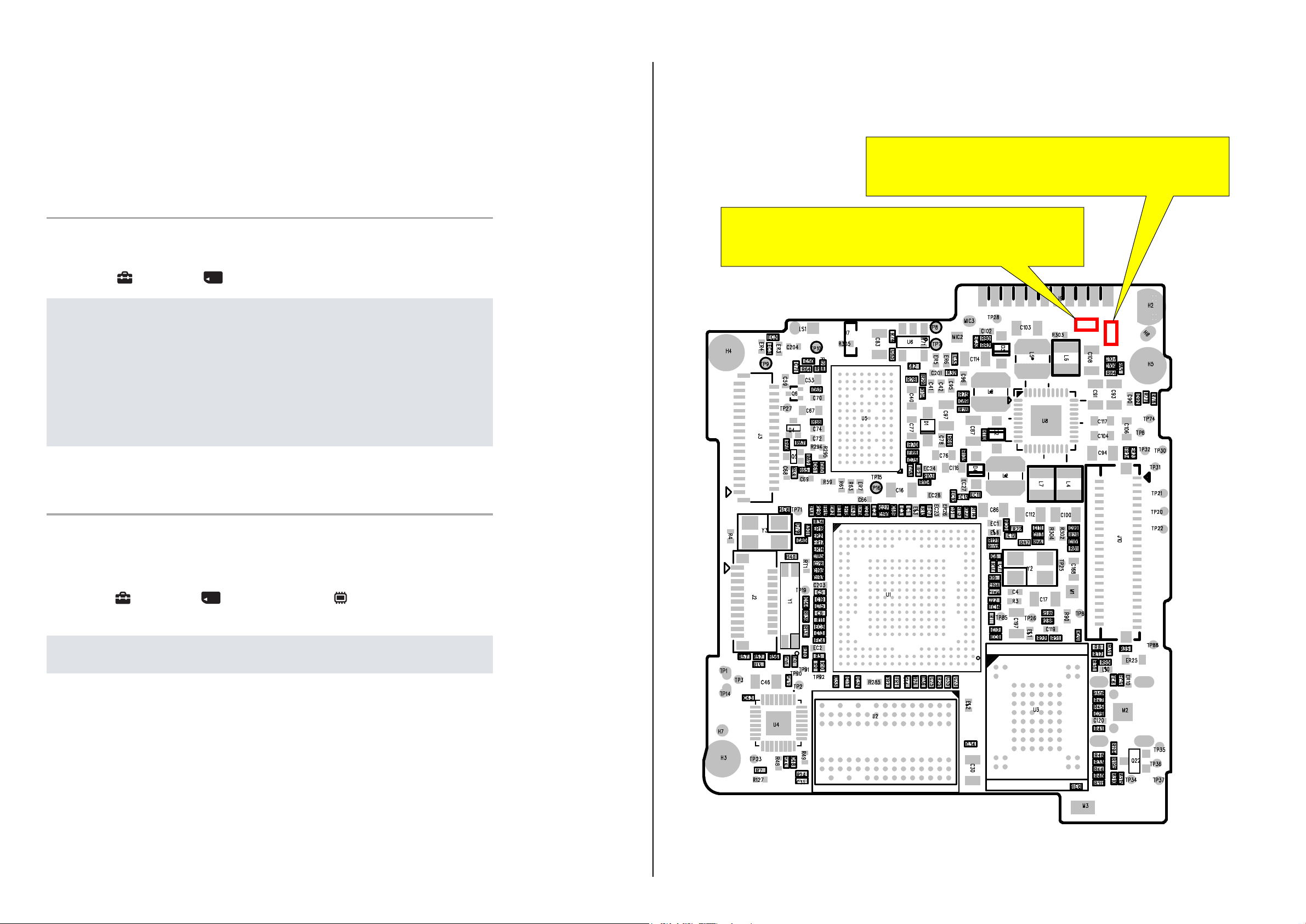
1-3. REGARDING FUSE
• MAIN BOARD
Ref. No: F1
Part No: 1-576-415-11
Description: FUSE, MICRO (1608 TYPE) (2A/32V)
Ref. No: F2
Part No: 1-576-415-11
Description: FUSE, MICRO (1608 TYPE) (2A/32V)
F1
F2
Method for Formatting the Internal Memory
Format
Formats the memory card or the internal memory. When you use a memory card with this
camera for the first time, it is recommended to format the card using the camera for stable
performance of the memory card before shooting. Note that formatting permanently erases all
data on the memory card, and is unrecoverable. Save precious data on a computer, etc.
1. MENU
t [Format] t [OK] t z
Note
•
t
Note that formatting permanently erases all data including even protected images.
(Settings) t (Memory Card Tool) or (Internal Memory Tool)
1-2. DEDICATED A/V CABLE (OPTIONAL ACCESSORY)
Dedicated A/V cable is not supplied with this model.
For details of the dedicated A/V cable, refer to the “Checking supplied accessories” page.
DSC-W510
1-1
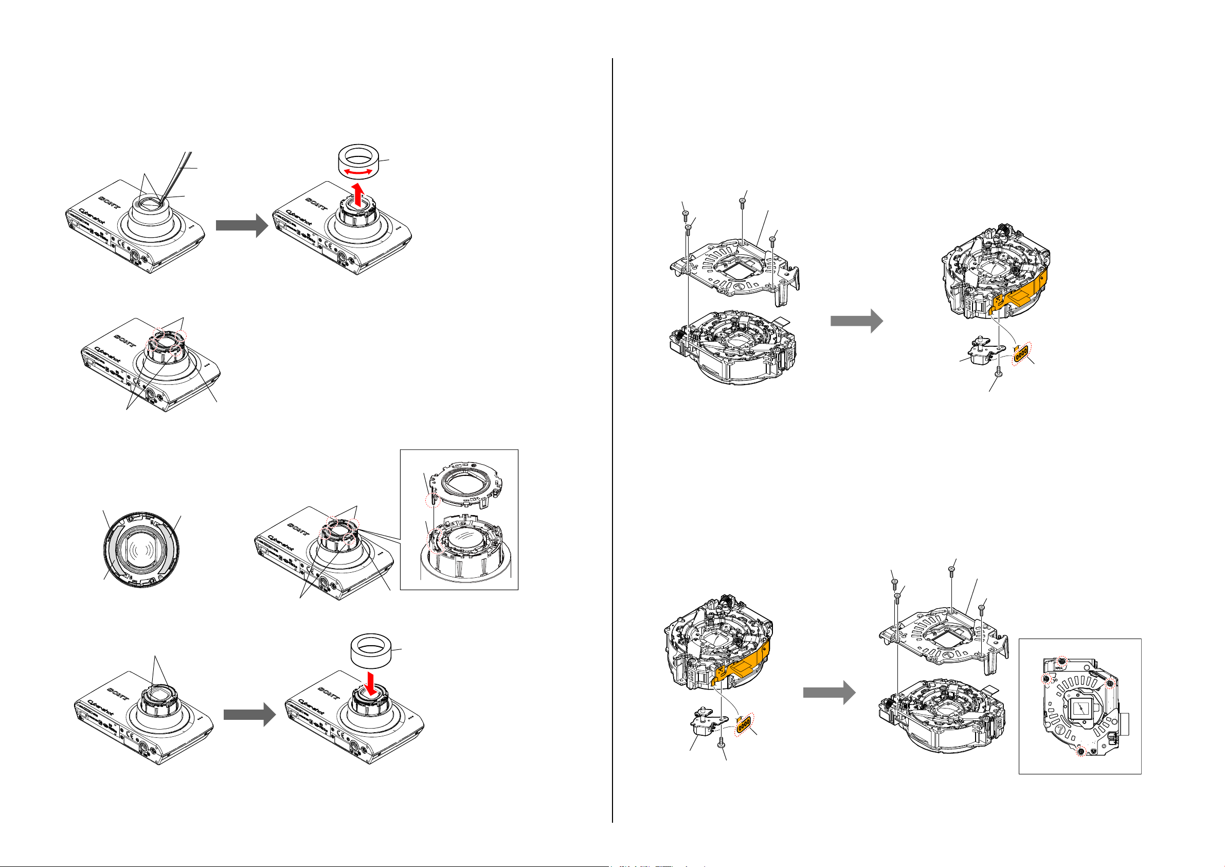
1-4. ORNAMENTAL RING A OR BARRIER ASSY REPLACING METHOD
REMOVAL
1 Turn on the power switch and extend the lens.
2 Detach the battery.
3 Pour a solvent such as alcohol from two places A to the tweezers or a needle shown below into a gap of Ornamental Ring A.
4
Remove while turning the Ornamental Ring A right and left.
A
5
Remove Barrier Assy by disengaging four claws.
Tweezers
Solvent
Claw
Ornamental Ring A
1-5. OPTICAL STEPPING MOTOR (F1380) REPLACING METHOD
REMOVAL
1
Remove four screws, and remove the Rear Mirror Plate.
2
Remove one screw.
3
Remove the four soldering, and remove the Optical Stepping Motor (F1380).
Screw
Screw
Screw
Rear Mirror Plate
Screw
Claw
INSTALLATION
Affix two Barrier Tapes to Barrier Assy.
1
Note:
The tape must not be wrinkled.
With four claws fitted in position, install the Barrier Assy.
2
Barrier Assy
Barrier Tape
3
Peel off release papers of Barrier Tapes.
4
Install Ornamental Ring A and press it lightly.
Barrier Tape
Barrier Tape
Barrier Assy
Claw
Claw
Barrier
Lever
Hole
Barrier Assy
Ornamental Ring A
INSTALLATION
1 Solder the four locations.
2
Install the Optical Stepping Motor (F1380) with one screw.
*
Tightening torque = 0.049±0.01N•m (0.5±0.1kgf•cm)
3
Install the Rear Mirror Plate with the four screws in the order of numbers.
*
Tightening torque = 0.049±0.01N•m (0.5±0.1kgf•cm)
Screw
Optical Stepping
Motor (F1380)
Screw
Solder
Screw
Screw
Rear Mirror Plate
Screw
4
DSC-W510
1-2
Optical Stepping
Motor (F1380)
Screw
Solder
1
2
3
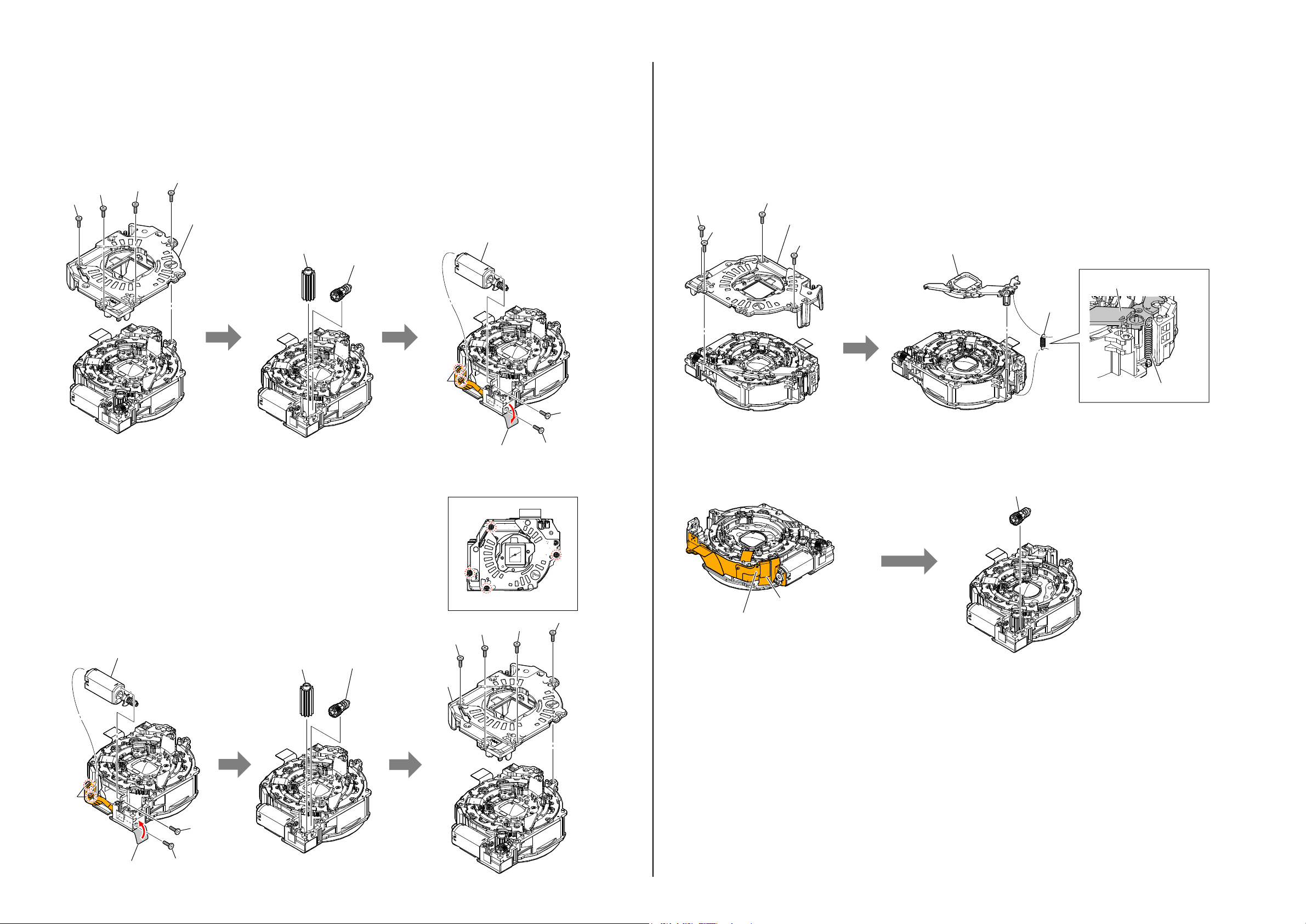
1-6. DC MOTOR WORM A ASSY REPLACING METHOD
REMOVAL
1
Remove four screws, and remove the Rear Mirror Plate.
2
Remove the Naruto Gear Lubricated Assy and Warm B Lubricated Assy.
3 Peel off the FG Seal.
4
Remove two screws.
5
Remove the two soldering, and remove the DC Motor Worm A Assy.
Screw
Rear Mirror Plate
Naruto Gear
Lubricated Assy
Warm B
Lubricated Assy
Screw
Screw
Screw
DC Motor Worm A Assy
1-7. CAM TUBE BLOCK ASSY AND STRAIGHT TUBE LUBRICATED ASSY AND
1 GROUP FRAME REPLACING METHOD
REMOVAL
Remove four screws, and remove the Rear Mirror Plate.
1
Remove the 3 Group Spring.
2
3
Remove the 3 Group Frame.
Screw
Screw
Screw
Rear Mirror Plate
Screw
3 Group Frame
3 Group Frame
3 Group
Spring
INSTALLATION
1 Solder the two locations.
2
Install the DC Motor Worm A Assy with two screws.
∗
Tightening torque = 0.049±0.01N•m (0.5±0.1kgf•cm)
2 Put the FG Seal.
2 Install the Naruto Gear Lubricated Assy and Warm B Lubricated Assy.
3
Install the Rear Mirror Plate with the four screws in the order of numbers.
∗
Tightening torque = 0.049±0.01N•m (0.5±0.1kgf•cm)
DC Motor Worm A Assy
Naruto Gear
Lubricated Assy
Warm B
Lubricated Assy
Solder
Screw
Rear Mirror Plate
4
FG Seal
1
Screw
2
Screw
Screw
Screw
Screw
3
4 Disconnect the Iris Flexible Board from connector of 2 Frame Assy.
Remove the Naruto Gear Lubricated Assy.
5
Flexible Board
Iris Flexible Board
of 2 Frame Assy
3 Group Spring
Warm B
Lubricated Assy
Solder
DSC-W510
FG Seal
Screw
Screw
1-3
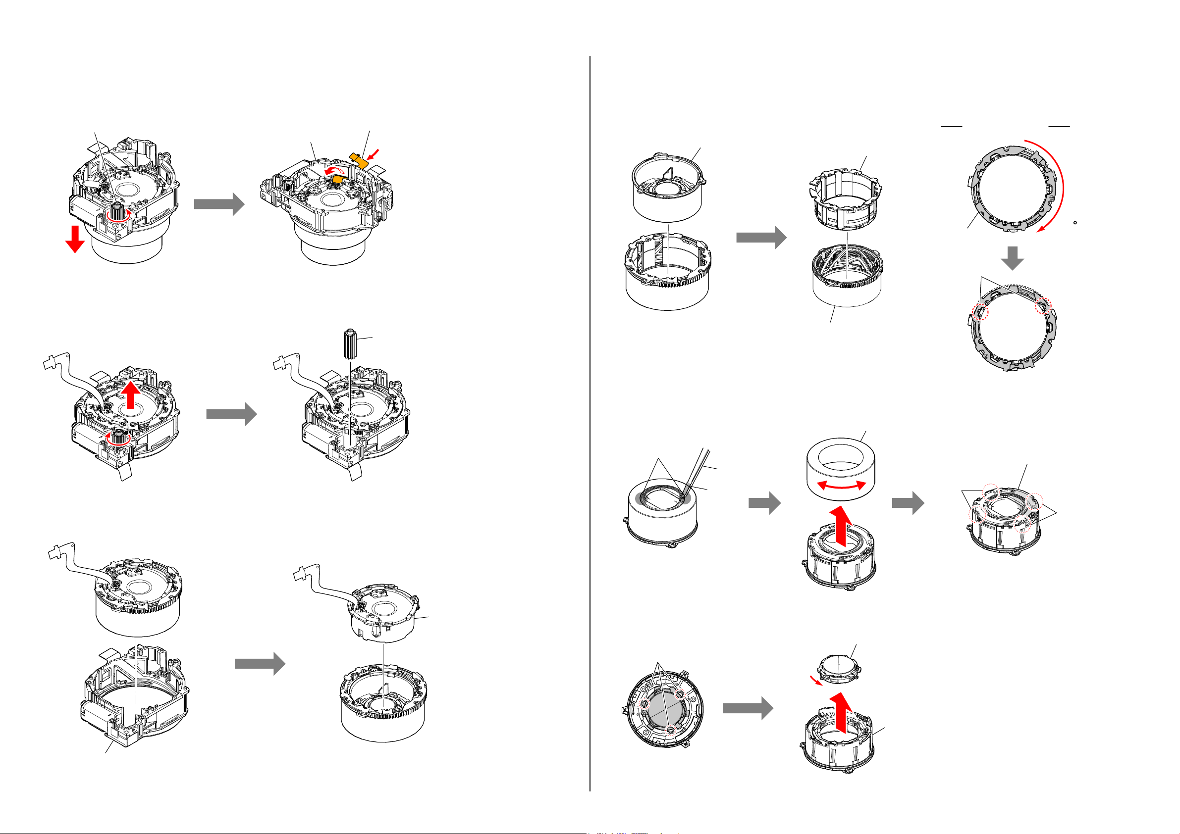
6 Rotate the Naruto Gear Lubricated Assy and the lens is drawn out.
7 Pass the Flexible Board through the hole of the Fixed Stationary Tube.
qs
Remove the 1 Group Assy.
qd Rotate (about 120 degree) Straight Tube Lubricated Assy and align the two points of ditches of the Straight Tube Lubricated Assy with
ditches of the Cam Tube Block Assy, then remove the Straight Tube Lubricated Assy from the Cam Tube Block Assy.
Naruto Gear Lubricated Assy
8 Rotate the Naruto Gear Lubricated Assy and the lens is retractile..
9 Remove the Naruto Gear Lubricated Assy.
Fixed Stationary Tube
Flexible Board
Naruto Gear
Lubricated Assy
1 Group Assy
Cam Tube Block Assy
qf
Pour a solvent such as alcohol from two places.
qg
Remove while turning the Ornamental Ring A right and left.
qh
Remove Barrier Assy by disengaging four claws.
Eyepiece Side View
Straight Tube
Lubricated Assy
120
Straight Tube
Lubricated Assy
Ditch
Ornamental Ring A
q; Remove the Fixed Stationary Tube Block.
qa Remove the 2 Group Assy.
2 Group Assy
A
Tweezers
Solvent
qj
Remove the bond at the three points.
qk
Rotate 1 Group Lens Assy and remove it from the 1 Group Frame.
Bond
Barrier Assy
Claw
Claw
1 Group Lens Assy
1 Group Frame
Fixed Stationary Tube Block
DSC-W510
1-4
 Loading...