

Sony DSC S500 - Cyber-shot Digital Camera Service Manual
Revision History
Revision History
How to use
Acrobat Reader
How to use
Acrobat Reader
Internal memory
ON BOARD
Internal memory
ON BOARD
SERVICE MANUAL
Link
Link
Sony EMCS Co.
DSC-S500
SERVICE NOTE
SPECIFICATIONS
BLOCK DIAGRAMS
DISASSEMBLY REPAIR PARTS LIST
Ver. 1.3 2007.08
DIGITAL STILL CAMERA
2007H0800-1
© 2007.08
Published by Kohda TEC9-852-124-12
US Model
Canadian Model
AEP Model
UK Model
E Model
Australian Model
Hong Kong Model
Korea Model
The components identified by
mark 0 or dotted line with
mark 0 are critical for safety.
Replace only with part number specified.
Les composants identifiés par une
marque 0 sont critiques pour la
sécurité.
Ne les remplacer que par une pièce
portant le numéro spécifié.
DSC-S500
In case of the lens assembly, main board, or main frame assembly failure,
contact your local Sony Service Headquarter for the measures.

— 2 —
DSC-S500
SPECIFICATIONS
[System]
Image device
7.17 mm (1/2.5 type) color CCD, Primary
color filter
Total pixel number of camera
Approx. 6 183 000 pixels
Effective pixel number of camera
Approx. 6 003 000 pixels
Lens
3× zoom lens
f = 5.4 - 16.2 mm (32 - 96 mm when
converted to a 35 mm still camera)
F2.8 - 4.8
Exposure control
Automatic exposure, Scene Selection (6
modes)
White balance
Automatic, Daylight, Cloudy, Fluorescent,
Incandescent
File format (DCF compliant)
Still images: Exif Ver. 2.21
JPEG compliant, DPOF compatible
Movies: AVI (Motion JPEG)
Recording media
Internal Memory (Approx. 25 MB)
“Memory Stick Duo” (with MagicGate/
without MagicGate)
“Memory Stick PRO Duo”
“MagicGate Memory Stick Duo”
Flash range
When ISO set to Auto: approx. 0.5 m to
2.5 m (19 3/4 inches to 98 1/2 inches) (W)/
approx. 0.5 m to 2.0 m (19 3/4 inches to 78
3/4 inches) (T)
[Input and Output connectors]
A/V OUT jack
Mini-jack
Video signal: 1 Vp-p, 75 Ω (ohms),
unbalanced, sync negative
Audio signal: 2 V (at load impedance more
than 47 kΩ (kilohms))
Output impedance with less than 2.2 kΩ
(kilohms)
USB jack
mini-B
USB communication
Full-Speed USB (USB 2.0 compliant)
[LCD screen]
LCD panel
6.0 cm (2.4 type) TFT drive
Total number of dots
110 000 (480 × 234) dots
[Power, general]
Power
LR6 (size AA) Alkaline batteries (2), 3 V
HR15/51:HR6 (size AA) Nickel-Metal
Hydride batteries (2) (not supplied), 2.4 V
ZR6 (size AA) Oxy Nickel Primary Battery
(2) (not supplied), 3 V
AC-LS5K AC Adaptor (not supplied), 4.2 V
Power consumption
(during shooting with the LCD screen on)
1.6 W
Operating temperature
0 to 40°C (32 to 104°F)
Storage temperature
–20 to +60°C (–4 to +140°F)
Dimensions
92 × 62 × 31 mm
(3 3/4 inches × 2 1/2 inches × 1 1/4 inches)
(W/H/D, excluding protrusions)
Mass
Approx. 198 g (7.0 oz) (including two
batteries and wrist strap, etc.)
Microphone
Electret condenser microphone
Buzzer
Piezo-electric buzzer
Exif Print
Compatible
PRINT Image Matching III
Compatible
PictBridge
Compatible
Design and specifications are subject to change
without notice.
— 3 —
DSC-S500
SAFETY-RELATED COMPONENT WARNING!!
COMPONENTS IDENTIFIED BY MARK 0 OR DOTTED LINE WITH
MARK 0 ON THE SCHEMATIC DIAGRAMS AND IN THE PARTS
LIST ARE CRITICAL TO SAFE OPERATION. REPLACE THESE
COMPONENTS WITH SONY PARTS WHOSE PART NUMBERS
APPEAR AS SHOWN IN THIS MANUAL OR IN SUPPLEMENTS
PUBLISHED BY SONY .
ATTENTION AU COMPOSANT AYANT RAPPORT
À LA SÉCURITÉ!
LES COMPOSANTS IDENTIFÉS P AR UNE MARQUE 0 SUR LES
DIAGRAMMES SCHÉMA TIQUES ET LA LISTE DES PIÈCES SONT
CRITIQUES POUR LA SÉCURITÉ DE FONCTIONNEMENT. NE
REMPLACER CES COMPOSANTS QUE PAR DES PIÈSES SONY
DONT LES NUMÉROS SONT DONNÉS DANS CE MANUEL OU
DANS LES SUPPÉMENTS PUBLIÉS PAR SONY.
1. Check the area of your repair for unsoldered or poorly-soldered
connections. Check the entire board surface for solder splashes
and bridges.
2. Check the interboard wiring to ensure that no wires are
"pinched" or contact high-wattage resistors.
3. Look for unauthorized replacement parts, particularly
transistors, that were installed during a previous repair. Point
them out to the customer and recommend their replacement.
4. Look for parts which, through functioning, show obvious signs
of deterioration. Point them out to the customer and
recommend their replacement.
5. Check the B+ voltage to see it is at the values specified.
6. FLEXIBLE Circuit Board Repairing
•Keep the temperature of the soldering iron around 270°C
during repairing.
•Do not touch the soldering iron on the same conductor of the
circuit board (within 3 times).
•Be careful not to apply force on the conductor when soldering
or unsoldering.
Unleaded solder
Boards requiring use of unleaded solder are printed with the leadfree mark (LF) indicating the solder contains no lead.
(Caution: Some printed circuit boards may not come printed with
the lead free mark due to their particular size.)
: LEAD FREE MARK
Unleaded solder has the following characteristics.
• Unleaded solder melts at a temperature about 40°C higher than
ordinary solder.
Ordinary soldering irons can be used but the iron tip has to be
applied to the solder joint for a slightly longer time.
Soldering irons using a temperature regulator should be set to
about 350°C.
Caution: The printed pattern (copper foil) may peel away if the
heated tip is applied for too long, so be careful!
• Strong viscosity
Unleaded solder is more viscous (sticky , less prone to flo w) than
ordinary solder so use caution not to let solder bridges occur such
as on IC pins, etc.
• Usable with ordinary solder
It is best to use only unleaded solder but unleaded solder may
also be added to ordinary solder.
SAFETY CHECK-OUT
After correcting the original service problem, perform the following
safety checks before releasing the set to the customer.
CAUTION
Danger of explosion if battery is incorrectly replaced.
Replace only with the same or equivalent type.

— 4 —
DSC-S500
TABLE OF CONTENTS
1. SERVICE NOTE
1-1. Process After Fixing Flash Error·····································1-1
1-2. Method for Copying or Erasing the Data in Internal
Memory ···········································································1-1
2. DISASSEMBLY
2-1. Disassembly·····································································2-1
3. BLOCK DIAGRAMS
3-1. Overall Block Diagram ···················································3-1
3-2. Power Block Diagram ·····················································3-2
4. REPAIR PARTS LIST
4-1. Exploded Vie ws ·······························································4-1
4-1-1. Overall Section······························································4-1
4-1-2. Front Block ···································································4-2
4-1-3. Main Frame Block ························································4-3
4-2. Accessories ······································································4-4
Section Title Page
1-1
DSC-S500
1. SERVICE NOTE
1-1. PROCESS AFTER FIXING FLASH ERROR
Method for Initializing the Flash Error
Initializes the setting to the default setting.
1 Select [OK] with v on the control button, then press z.
The message “Initialize all settings Ready?” appears.
2 Select [OK] with v, then press z.
The settings are rese t to the default setting.
• Make sure that the power is not disconnected during resetting.
Initialize
OK
See the following procedure.
Cancel
Cancels the resettin g.
Copies all images in the internal memory to a “Memory Stick Duo”.
1 Insert a “Memory Stick Duo” having 16 MB or larger capacity.
2 Select [OK] with v on the control button, then press z.
The message “All data in internal memory will be copied Ready?” appears.
3 Select [OK] with v, then press z.
Copying starts.
Copy
OK
See the following procedure.
Cancel
Cancels the copying.
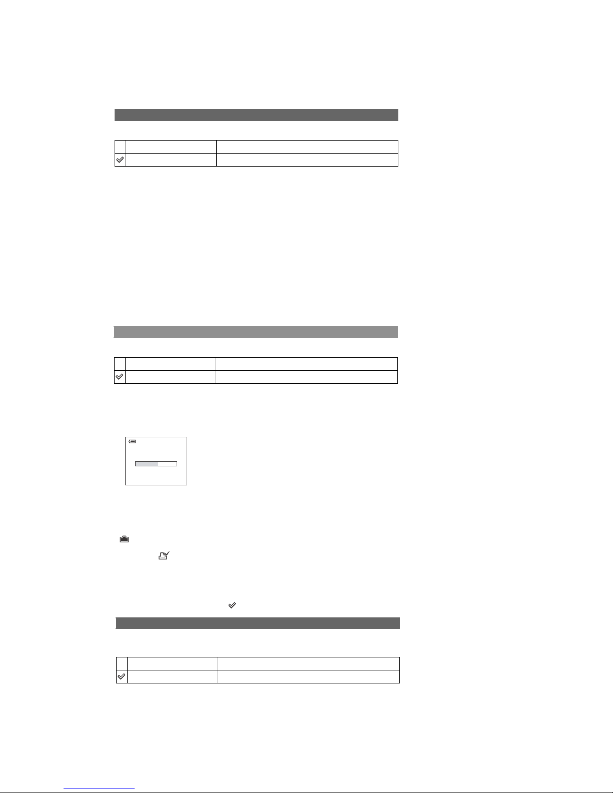
Copying
102_COPY
Use batteries with enough capacity or the AC Adaptor (not supplied). If you attempt to copy image files
using batteries with little remaining charge, the batteries may run out, causing copying to fail or possibly
corrupting the data.
You cannot copy individual images.
The original images in the internal memory are retained even after copying. To delete the contents of the
internal memory, remove the “Memory Stick Duo” after copying, then execute the [Format ] command in
Internal Memory Tool.
You cannot select a folder copied on a “Memory Stick Duo ”.
The setting of (Print order)marks is not copied even when you copy data.
•
•
•
•
•
1-2. METHOD FOR COPYING OR ERASING THE DATA IN INTERNAL MEMORY
The data can be copied/erased by the operations on the Setup screen. (When erasing the data, execute formatting the internal memory.)
Note: When replacing the camera, erase the data in internal memory of the board before replacement.
Method for Copying the Data in Internal Memory
Method for Formatting the Internal Memory
This item does not appear when a “Memory Stick Duo” is inserted in the camera.
The default settings are marked with .
Formats the internal memo r y.
• Note that formatting irrevocably erases all data in the internal memory, including even protected images.
1 Select [OK] with v on the control button, then press z.
The message “All data in internal memory will be erased Ready?” appears.
2 Select [OK] with v, then press z.
The format is complete.
Format
OK
See the following procedure.
Cancel
Cancels the formatti ng.
2-1
DSC-S500
1
2
3
1
1
1
1
2
3
2
4
1
1
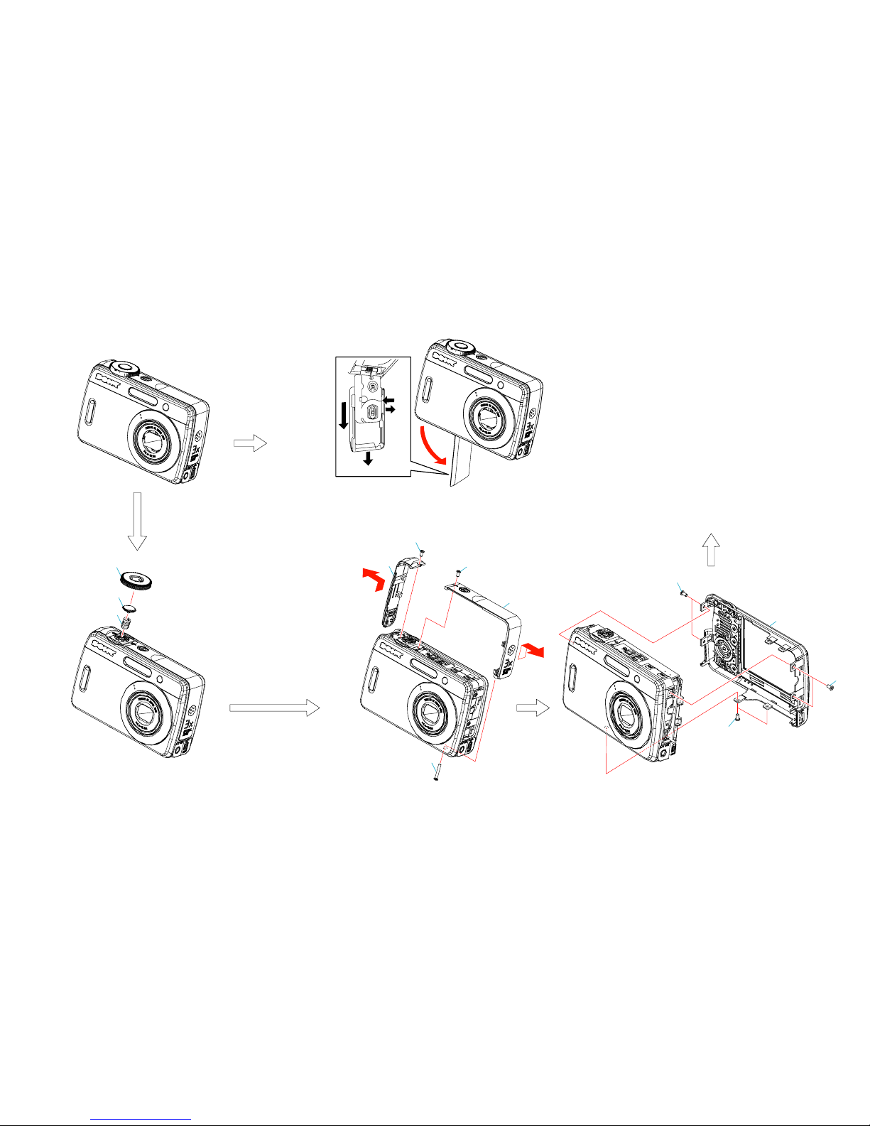
Two tapping screws (M1.7x3.5) silver
2
Middle cover assembly (right)
3
Tapping screw (M1.7x16) silver
4
Inner belt (left)
Front section
(See page 2-2.)
1
Mode dial
2
Shutter button
3
Shutter button spring
1
Six tapping screws (M1.7x3.5) silver
2
Rear cover assembly
Take it off pulling over to upward.
Push down adjusting rib width when attaching.
Battery case lid removal
1
Pull out the battery case slowly until stop.
2
Put a nail into a slot.
3
Pull the battery case in the direction of arrow A.
A
1
2
3
2. DISASSEMBLY
2-1. DISASSEMBLY
The following flow chart shows the disassembly procedure.
 Loading...