

Page 1
DSC-F77/FX77
Ver 1.0 2002. 10
Revision History
Revision History
Link
Link
Before starting adjustments
Before starting adjustments
Adjusting items when replacing main parts and boards
Adjusting items when replacing main parts and boards
CAMERA SECTION ADJUSTMENTS
CAMERA SECTION ADJUSTMENTS
PREPARATIONS BEFORE ADJUSTMENTS
PREPARATIONS BEFORE ADJUSTMENTS
INITIALIZATION OF A, B, D, E, F, 7, 9 PAGE DATA
INITIALIZATION OF A, B, D, E, F, 7, 9 PAGE DATA
VIDEO SYSTEM ADJUSTMENTS
VIDEO SYSTEM ADJUSTMENTS
CAMERA SYSTEM ADJUSTMENTS
CAMERA SYSTEM ADJUSTMENTS
LCD SYSTEM ADJUSTMENTS
LCD SYSTEM ADJUSTMENTS
SECTION 6
ADJUSTMENTS
SERVICE MODE
SERVICE MODE
ADJUSTING REMOTE COMMANDER
ADJUSTING REMOTE COMMANDER
DATA PROCESS
DATA PROCESS
SERVICE MODE
SERVICE MODE
ADJ
Contents of LEVEL 2 and LEVEL 3 Service Manual
CONTENTS
1. SERVICE NOTE
2. DISASSEMBLY
3. BLOCK DIAGRAMS
4. PRINTED WIRING BOARDS AND
SCHEMATIC DIAGRAMS
5. REPAIR PARTS LIST
OVERALL
POWER
CD-415 BOARD, ST-78
BOARD, KK-29 BOARD,
FP-585 FLEXIBLE, FP-586
FLEXIBLE
EXPLODED VIEWS
ELECTRICAL PARTS LIST
LEVEL 2
a
a
LEVEL 3
✕
✕
✕
SY-81 BOARD,
BT-14 BOARD (FX77)
✕
a
BT-14 BOARD (FX77),
(
SY-81 BOARD
)
9-929-997-51
Sony EMCS Co.
2002J0500-1
©2002.10
Published by DI Customer Center
Page 2

DSC-F77/FX77
TABLE OF CONTENTS
Section Title Page Section Title Page
6. ADJUSTMENTS
Before Starting Adjustment ·······················································6-1
1-1. Adjusting Items when Replacing
Main Parts and Boards ····················································6-2
6-1. Camera Section Adjustments··········································· 6-3
1-1. Preparations Before Adjustments ····································6-3
1-1-1.List of Service Tools ························································6-3
1-1-2.Preparations ·····································································6-4
1-1-3.Discharging of the Flashlight Power Supply···················6-4
1-1-4.Precautions ······································································6-6
1. Setting the Switch····························································6-6
2. Order of Adjustments ······················································ 6-6
3. Subjects ···········································································6-6
4. Preparing the Flash Adjustment Box·······························6-7
1-2. Initialization of A, B, D, E, F, 7, 9 Page Data ·················6-8
1-2-1.Initialization of A, D Page Data ······································6-8
1. Initializing A, D Page Data ··············································6-8
2. Modification of A, D Page Data ······································6-8
3. A Page Table···································································· 6-8
4. D Page Table···································································· 6-8
1-2-2.Initialization of B, E, F, 7, 9 Page Data ··························· 6-9
1. Initializing B, E, F, 7, 9 Page Data ··································6-9
2. Modification of B, E, F, 7, 9 Page Data···························6-9
3. B Page Table ····································································6-9
4. E Page Table ····································································6-9
5. F Page Table ··································································6-10
6. 7 Page Table···································································6-12
7. 9 Page Table···································································6-12
1-2-3.Initialization of Bluetooth ·············································6-12
1. Initializing of Bluetooth Revision History ···················· 6-12
2. Checking of Bluetooth Function ···································6-12
1-3. Video System Adjustments············································6-13
1. Video Sync Level Adjustment ·······································6-13
2. Video Burst Level Check··············································· 6-13
1-4. Camera System Adjustments·········································6-14
Data Setting During Camera System Adjustments········6-14
Picture Frame Setting ···················································· 6-15
1. HALL Adjustment ·························································6-16
2. Flange Back Adjustment
(Using the minipattern box) ··········································6-17
3. Flange Back Adjustment
(Using the flange back adjustment chart)······················ 6-18
4. Flange Back Check························································6-18
5. F No. Compensation······················································ 6-19
6. Mechanical Shutter Adjustment ···································· 6-19
7. Light V alue Adjustment················································· 6-20
8. Mixed Color Cancel Adjustment···································6-20
9. Auto White Balance 3200K Standard Data Input ·········6-21
10. Auto White Balance 5800K Standard Data Input ·········6-22
11. Auto White Balance 5800K Check 1 ····························6-23
12. Auto White Balance 5800K Check 2 ····························6-24
13. Auto White Balance 5800K Check 3 ····························6-25
14. Auto White Balance 3200K Check 1 ····························6-26
15. Auto White Balance 3200K Check 2 ····························6-27
16. Auto White Balance 3200K Check 3 ····························6-28
17. Color Reproduction Adjustment····································6-29
18. CCD White Defect Compensation ································6-30
19. CCD Black Defect Compensation·································6-31
20. Strobe White Balance Adjustment·································6-32
21. AF Illumination Check ··················································6-33
1-5. LCD System Adjustments ·············································6-34
1. LCD Initial Data Input (1)············································· 6-35
2. LCD Initial Data Input (2)············································· 6-35
3. VCO Adjustment (SY-81 Board)···································6-36
4. PSIG Level Adjustment (SY-81 Board) ························ 6-36
5. Bright Adjustment (SY-81 Board)·································6-37
6. Contrast Adjustment (SY-81 Board)······························6-37
7. VG Center Adjustment (SY-81 Board)··························6-38
8. V-COM Adjustment (SY-81 Board) ······························6-38
9. White Balance Adjustment (SY-81 Board) ···················6-39
6-2. Service Mode·································································6-40
2-1. Adjusting Remote Commander ·····································6-40
1. Used the Adjusting Remote Commander ······················6-40
2. Precautions upon Using the Adjusting
Remote Commander······················································ 6-40
2-2. Data Process ··································································6-41
2-3. Service Mode·································································6-42
1. Setting the Test Mode ····················································6-42
2. Bit Value Discrimination ···············································6-42
3. Mode Dial Check (1) ·····················································6-43
4. Mode Dial Check (2) ·····················································6-43
5. Switch Check (1) ···························································6-43
6. Switch Check (2) ···························································6-43
7. Switch Check (3) ···························································6-43
8. Switch Check (4) ···························································6-44
9. LED Check ····································································6-44
10. Self Diagnosis Code ······················································ 6-44
* The color reproduction frame is shown on page 6-45
— 2 —
Page 3
COVER
COVER
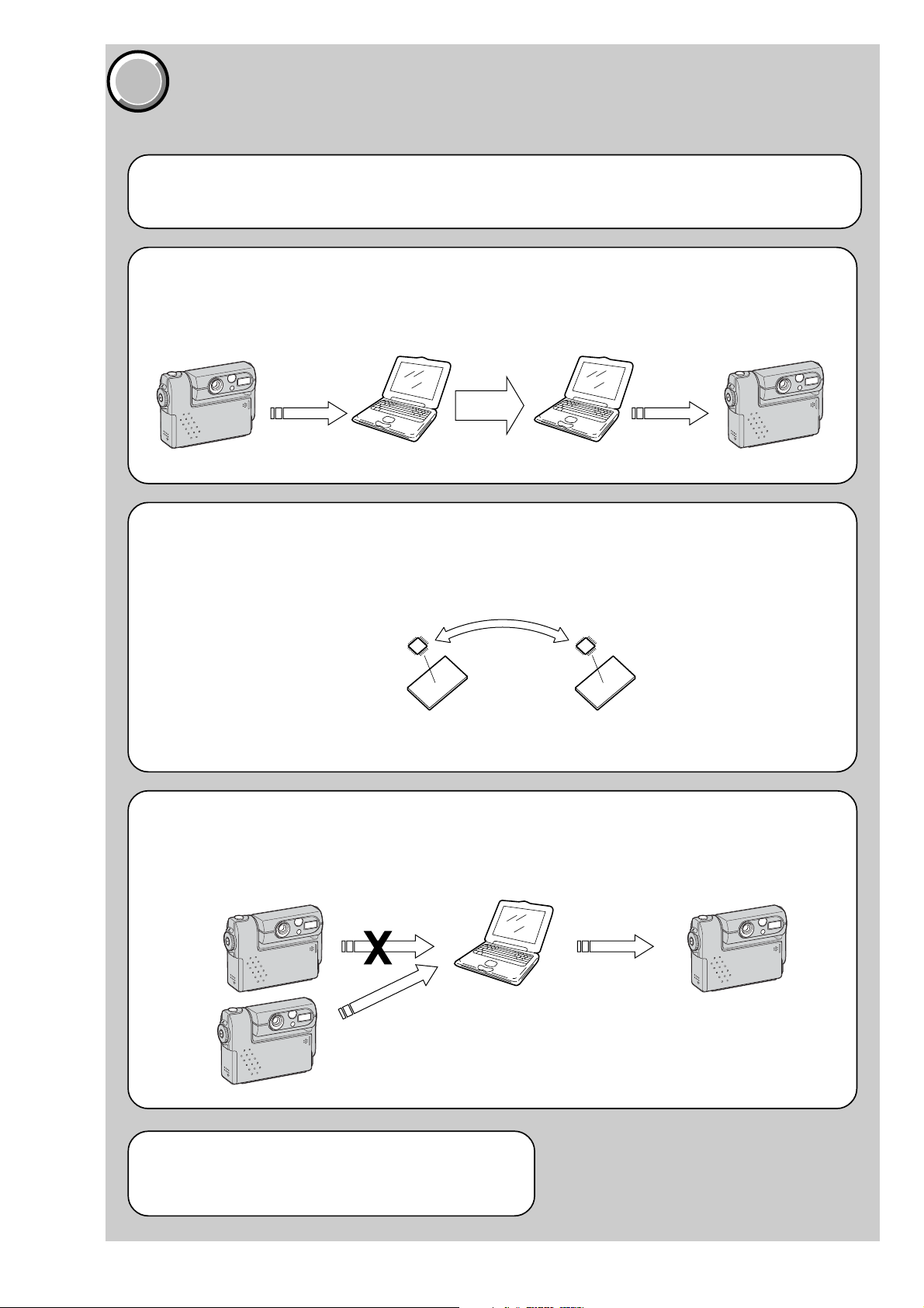
Before starting adjustment
EVR Data Re-writing Procedure When Replacing Board
The data that is stored in the repair board, is not necessarily correct.
Perform either procedure 1 or procedure 2 or procedure 3 when replacing board.
Procedure 1
Save the EVR data of the machine in which a board is going to be replaced. Download the saved data after a
board is replaced.
DSC-F77/FX77
SECTION 6
ADJUSTMENTS
(Machine before starting repair)
Save the EVR data
to a personal computer.
Procedure 2
Remove the EEPROM from the board of the machine tha t is going to be repaired. Install the removed EEPR OM
to the replaced board.
PC PC
Remove the EEPROM and install it.
(Former board)
(New board)
(Machine after a board is replaced)
Download the saved
data to a machine.
Procedure 3
When the data cannot be saved due to defective EEPROM, or when the EEPROM cannot be removed or installed, save the data from the same model of the same destination, and download it.
(Machine to be repaired)
Download the data.
Save the data.
(The same model of the same destination)
After the EVR data is saved and downloaded, check the
respective items of the EVR data.
(Refer to page 6-2 for the items to be checked.)
(Machine to be repaired)PC
6-1
Page 4
DSC-F77/FX77
RadarW
RadarW
COVER
COVER
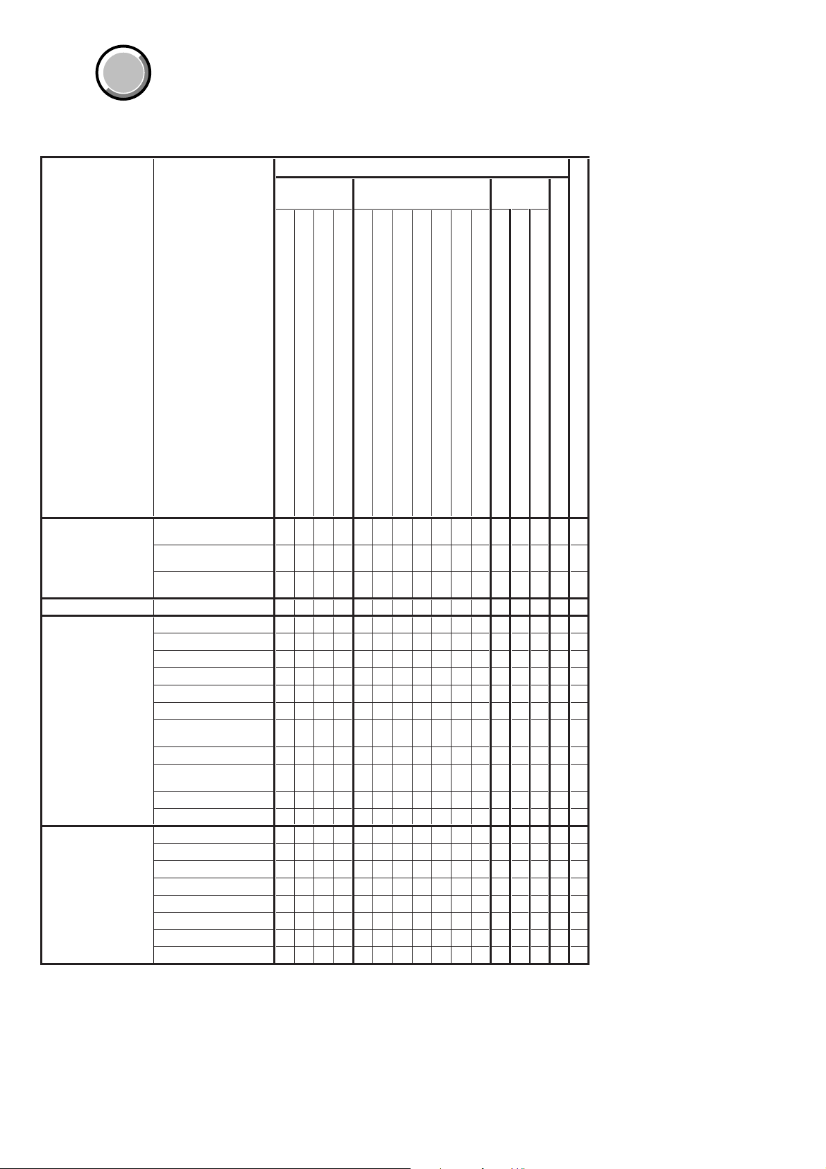
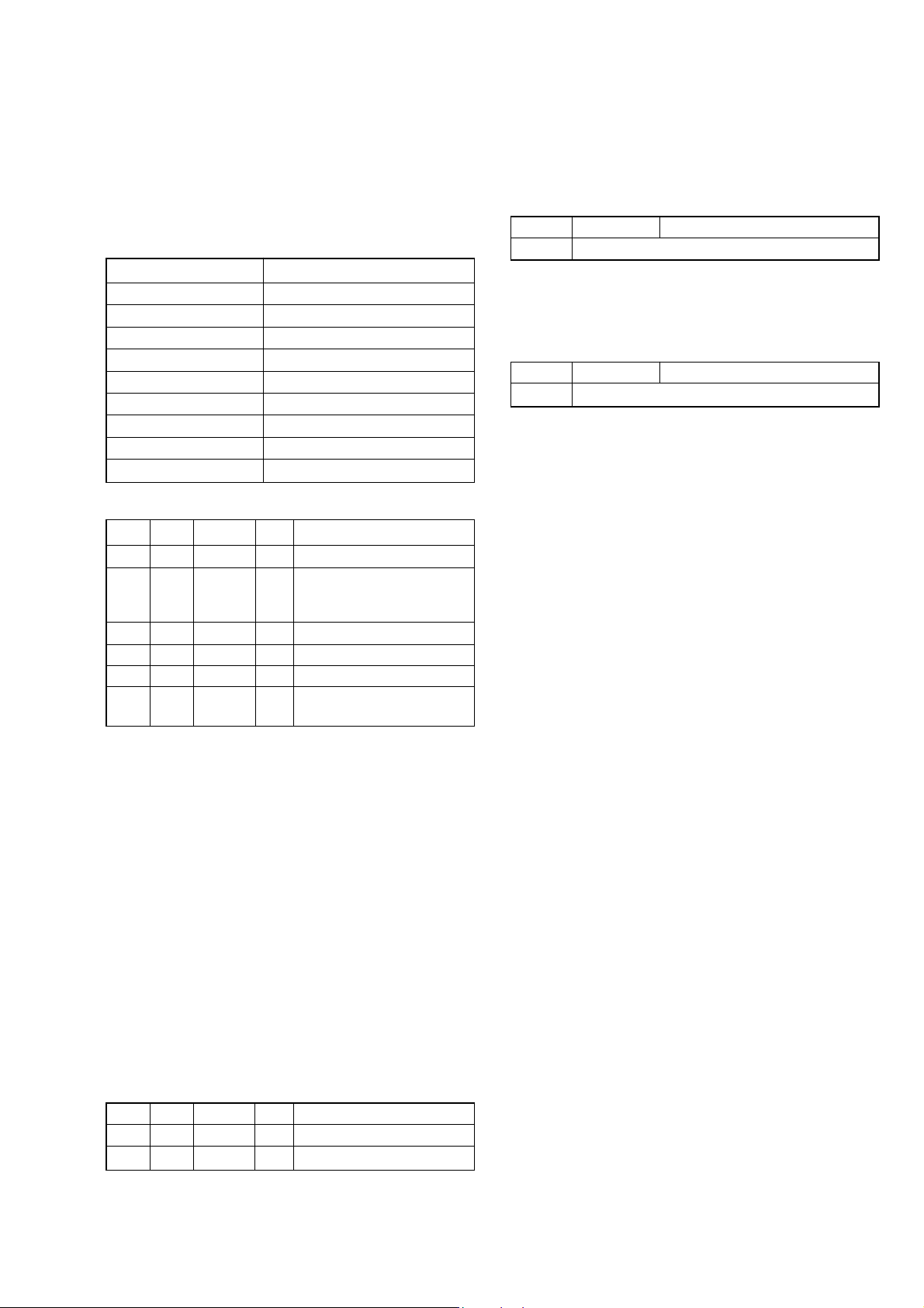
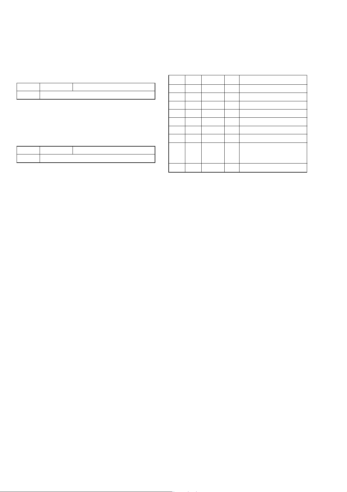
1-1. Adjusting items when replacing main parts and boards
When replacing main parts and boards, adjust the items indicated by z in the following table.
Replaced parts
Block Mounted parts Board
replacement replacement replacement
Note: DSC-FX77 only
Adjustment section Adjustment
Initialization of A, B, D,
E, F, 7, 9 page data
Video Video sync level adj.
Camera Hall adj.
LCD LCD initial data input
Initialization of
A, D page data
Initialization of
B, E, F, 7, 9 page data
Initialization of
Bluetooth (Note)
Flange back adj.
F No. compensation
Mechanical shutter adj.
Light value adj.
Mixed color cancel adj.
Auto white balance
standard data input
Color reproduction adj.
CCD (white and black)
defect compensation
Strobe white balance adj.
AF illumination check
VCO adj.
PSIG level adj.
Bright adj.
Contrast adj.
VG center adj.
V-COM adj.
White balance adj.
(LCD panel)
(Back light)
(CCD imager)
(Timing generator, S/H, AGC, A/D)
(EVR)
(Camera DSP, 128M SDRAM)
(VIDEO AMP)
(LCD drive)
(AF illuminator)
LCD901
D901
IC001
IC151
IC602
IC651
IC301
IC701
D102
(COMPLETE) (Note)
Lens block assy
Flash unit
LCD block
LCD block
CD-415 board
SY-81 board
SY-81 board
SY-81 board
SY-81 board
SY-81 board
ST-78 board
BT-14 board
zz
zz
zz z
zz z z
zzzzz
zz zzz
zz zzz
zzz zzz
zzz zzz
zz z zz
zz z zz
zz z zz
zzzz
zzz zzzz
zzzzzz
zz
zzz
zzz
zzz
zzz
zzz
zzzz
zz z z z
EEPROM
(COMPLETE)
(COMPLETE)
IC604
SY-81 board
ST-78 board
SY-81 board
RadarW
RadarW
RadarW
Supporting
Table 6-1-1
6-2
Page 5
COVER
COVER
6-1. CAMERA SECTION ADJUSTMENTS
1-1. PREPARATIONS BEFORE ADJUSTMENTS
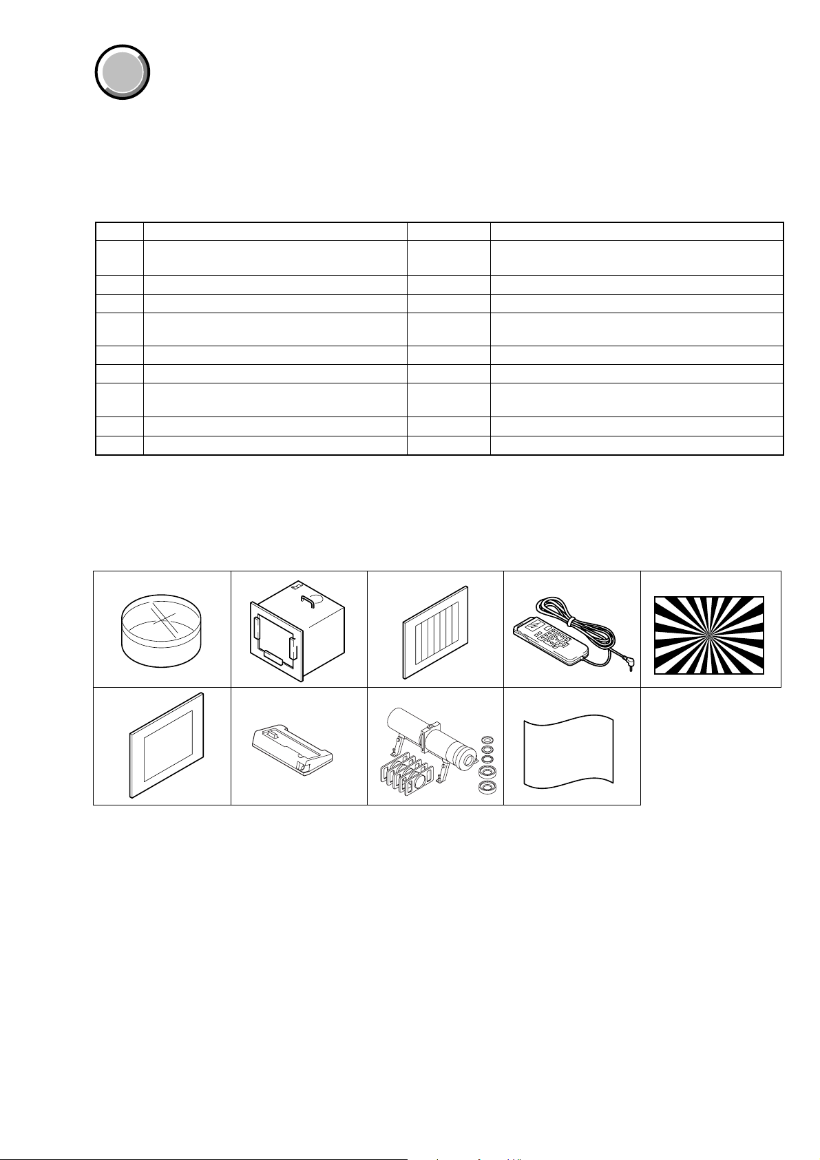
1-1-1. List of Service Tools
• Oscilloscope • Color monitor • Vectorscope
• Digital voltmeter • Frequency counter
DSC-F77/FX77
Ref. No.
J-1
Filter for color temperature correction (C14)
J-2
Pattern box PTB-450
J-3
Color bar chart for pattern box
Adjusting remote commander (RM-95 upgraded).
J-4
(Note 1)
J-5
Siemens star chart
J-6
Clear chart for pattern box
J-7
Cradle with LANC jack
J-8
Minipattern box
J-9 Back ground paper J-2501-130-A For adjusting the strobe
Note 1: If the micro processor IC in the adjusting remote
commander is not the new micro processor (UPD7503GC56-12), The pages cannot be switched. In this case,
replace with the new micro processor (8-759-148-35).
J-1
J-2
Name
Parts Code
J-6080-058-A
J-6082-200-A
J-6020-250-A
J-6082-053-B
J-6080-875-A
J-6080-621-A
J-6082-548-A
J-6082-353-B
J-3 J-4
Auto white balance adjustment/check
White balance adjustment/check
For checking the flange back
For connecting the adjusting remote commander
For connecting the color monitor
For adjusting the flange back
Usage
J-5
J-6 J-7
J-8 J-9
Fig. 6-1-1
6-3
Page 6
DSC-F77/FX77
1-1-2. Preparations
Note 1: For details of how remove the cabinet and boards, refer
to “2. DISASSEMBLY”.
Note 2: When performing only the adjustments, the lens block
and boards need not be disassemble.
1) Connect the equipment for adjustments according to Fig. 6-1-
5.
2) Connect the adjusting remote commander to cradle with LANC
jack (J-6082-548-A).
Note 3: Setting the “Forced CAMERA mode power ON Mode”
1) Select page: 0, address: 01, and set data: 01.
2) Select page: D, address: 21, set data: 04, and press
the PAUSE button of the adjusting remote commander.
The above procedure will enable the camera power
to be turned on. After completing adjustments, be
sure to exit the “Forced CAMERA mode power ON
Mode”.
Pattern box
Front of the lens
L
L = About 30 cm
Note 4: Exiting the “Forced CAMERA mode power ON Mode”
1) Select page: 0, address: 01, and set data: 01.
2) Select page: D, address: 21, set data: 00, and press
the PAUSE button of the adjusting remote commander.
3) Select page: 0, address: 01, and set data: 00.
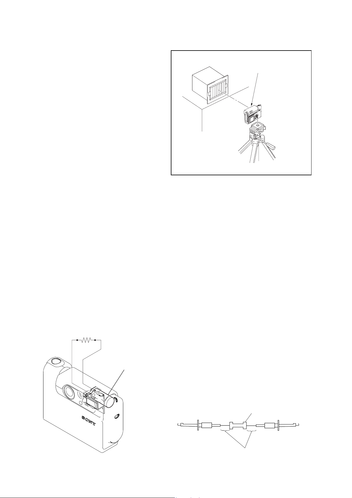
1-1-3. Discharging of the Flashlight Power Supply
The capacitor which is used as power supply of flashlight is charged
with 200 V to 300 V voltage. Discharge this voltage before starting adjustments in order to protect service engineers from electric
shock during adjustment.
Discharge procedure
1. Press the FLASH button (SY -81 board S855 (CONTR OL UP))
and set the NO FLASH mode.
2. Fabricate the discharging jig as shown in Fig. 6-1-4 locally by
yourself. Connect the discharging jig to the positive (+) and
negative (–) terminal of the flash voltag e charge capacitor . Allow ten seconds to discharge the voltage.
R:1 kΩ/1 W
(Part code:
1-215-869-11)
Fig. 6-1-2
Capacitor
1 kΩ/1 W
Wrap insulating tape.
Fig. 6-1-4Fig. 6-1-3
6-4
Page 7
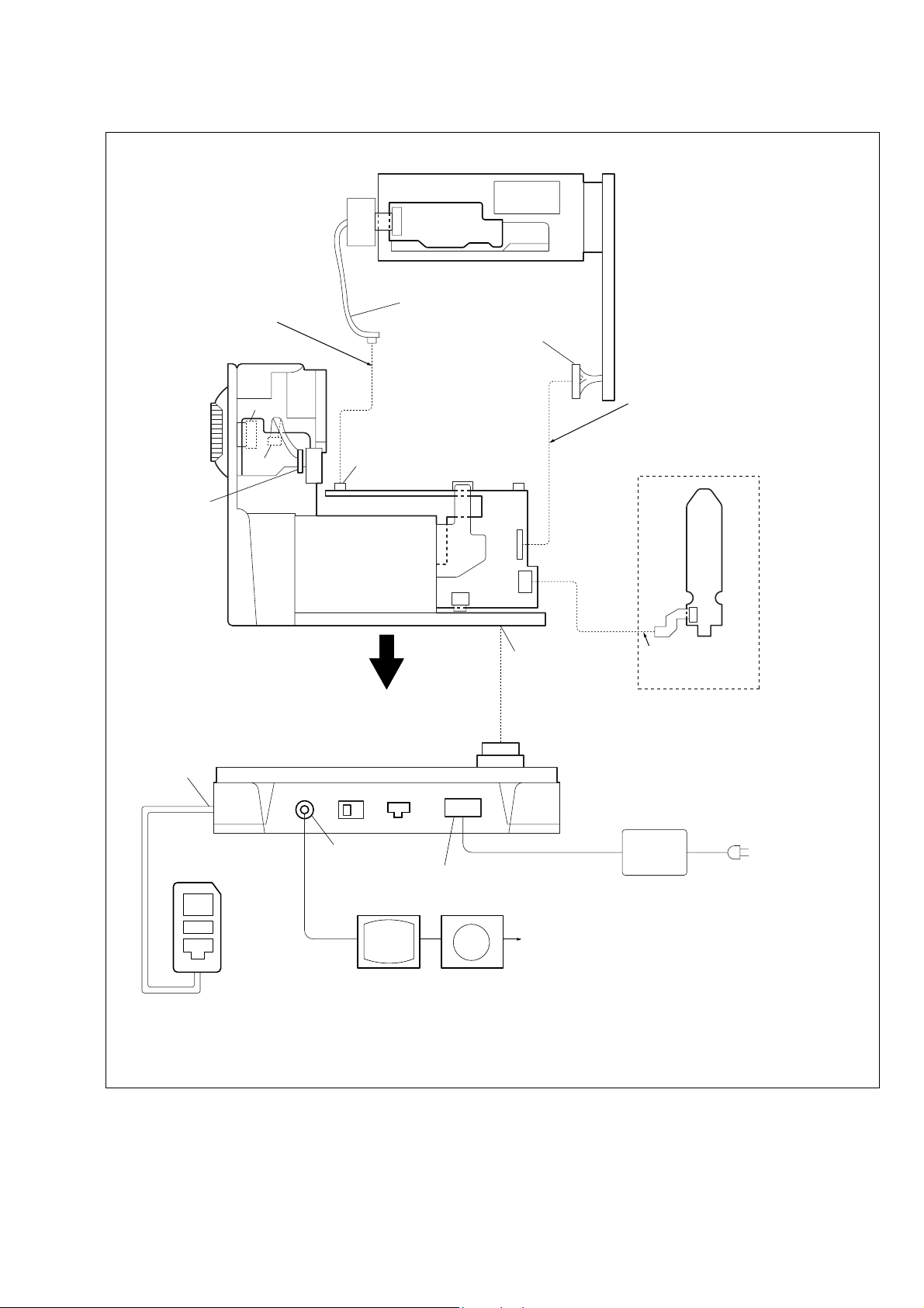
CN001
CD-415 board
DSC-F77/FX77
Must be connected when
performing the camrera system
adjustment. (Note 1)
CN853
CN851
KK-29
flexible
board
CN151
SY-81 board
FP-585 flexible
CN601
CN401
FP-587
flexible
SS-173 harness
CN402
CN351
CN352
Connect to
SY-81 board CN503
(Multi connector)
Must be connected when
performing the strobe adjustment
and AF illumination check. (Note 2)
DSC-FX77 only
BT-14 board
CN1001
Must be connected
when performing the
Bluetooth check.
Connect to
LANC jack
Adjustment remote
commander
Audio/Video jack
Color monitor
DC IN jack
Vectorscope
Cradle with LANC jack
(J-6082-548-A)
Terminated at 75 Ω
AC power adaptor
Note 1: When CN151 on SY-81 board is removed, turn on the power after setting the mode dial “PLAY”.
Note 2: When CN351 on SY-81 board is removed, press the FLASH button (CONTROL UP) to change to “NO FLASH” mode.
Fig. 6-1-5
6-5
Page 8
DSC-F77/FX77
1-1-4. Precautions
1. Setting the Switch
Unless otherwise specified, set the switches as follows and perform adjustments.
1. Mode Dial .......................................... CAMERA
2. ZOOM button
(SY-81 board S852, S853) ................. WIDE end
3. DSPL/LCD ON/OFF button
(SY-81 board S856) ........................... OSD OFF
4. VIDEO OUT (SET UP setting)......... NTSC
2. Order of Adjustments
Basically carry out adjustments in the order given.
Color bar chart (Standard picture frame)
H
Yellow
Cyan
White
Magenta
Green
AB B
A=B
Red
Blue
A
Enlargement
B
A
3. Subjects
1) Color bar chart (Standard picture frame).
When performing adjustments using the color bar chart, adjust the picture frame as shown in Fig. 6-1-6. (Standard picture frame)
2) Clear chart (Standard picture frame)
Remove the color bar chart from the pattern box and insert a
clear chart in its place. (Do not perform zoom operations during this time)
3) Chart for flange back adjustment
Join together a piece of white A0 size paper (1189mm × 841
mm) and a piece of black paper to make the chart shown in
Fig. 6-1-7.
C=D
V
Difference in level
DC
Fig. 6-1-6
Electronic beam scanning frame
Red
Cyan
White
Green
Yellow
Fig. b (monitor TV picture)
Adjust the camera zoom and direction to
obtain the output wavefor m shown in Fig a
and the monitor TV display shown in Fig. b.
Black
Magenta
1189 mm
Blue
CRT picture frame
White
841 mm
Note: Use a non-reflecting and non-glazing vellum paper. The
size must be A0 or larger and the joint between the white
and black paper must not have any undulations.
Fig. 6-1-7
6-6
Page 9
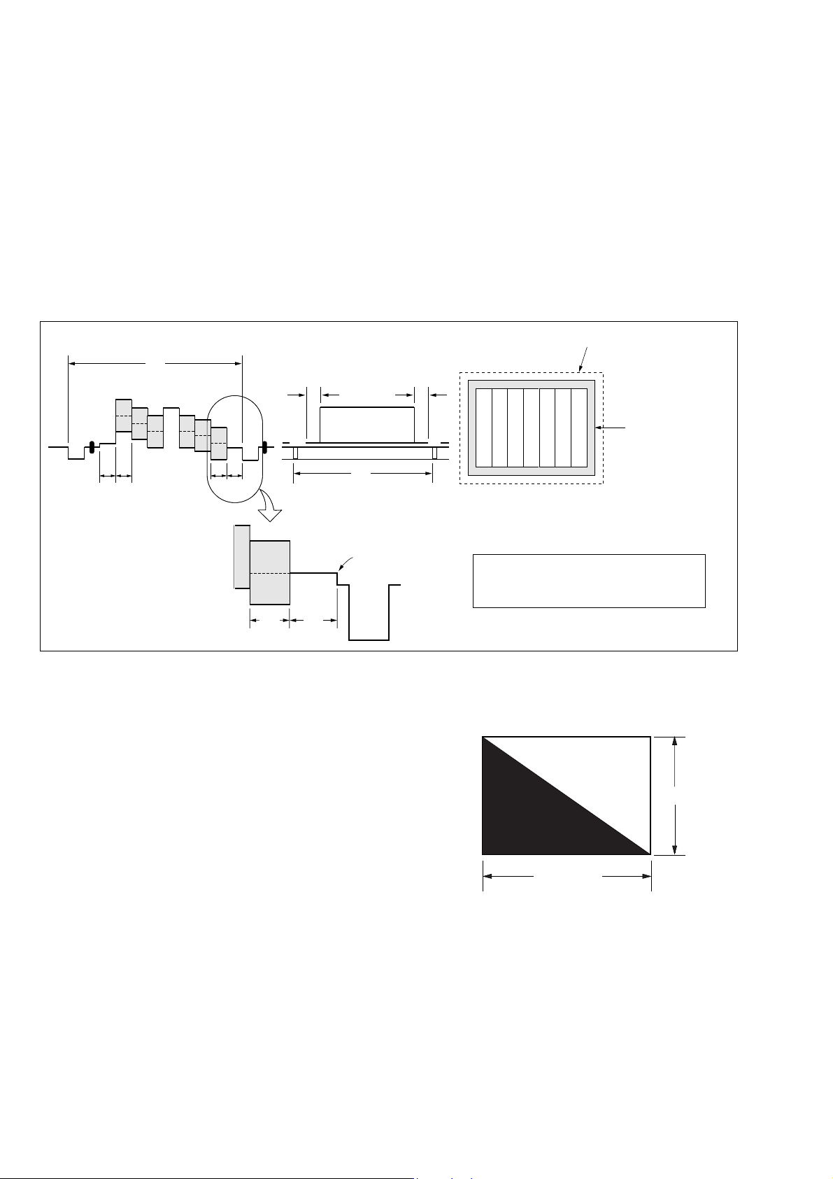
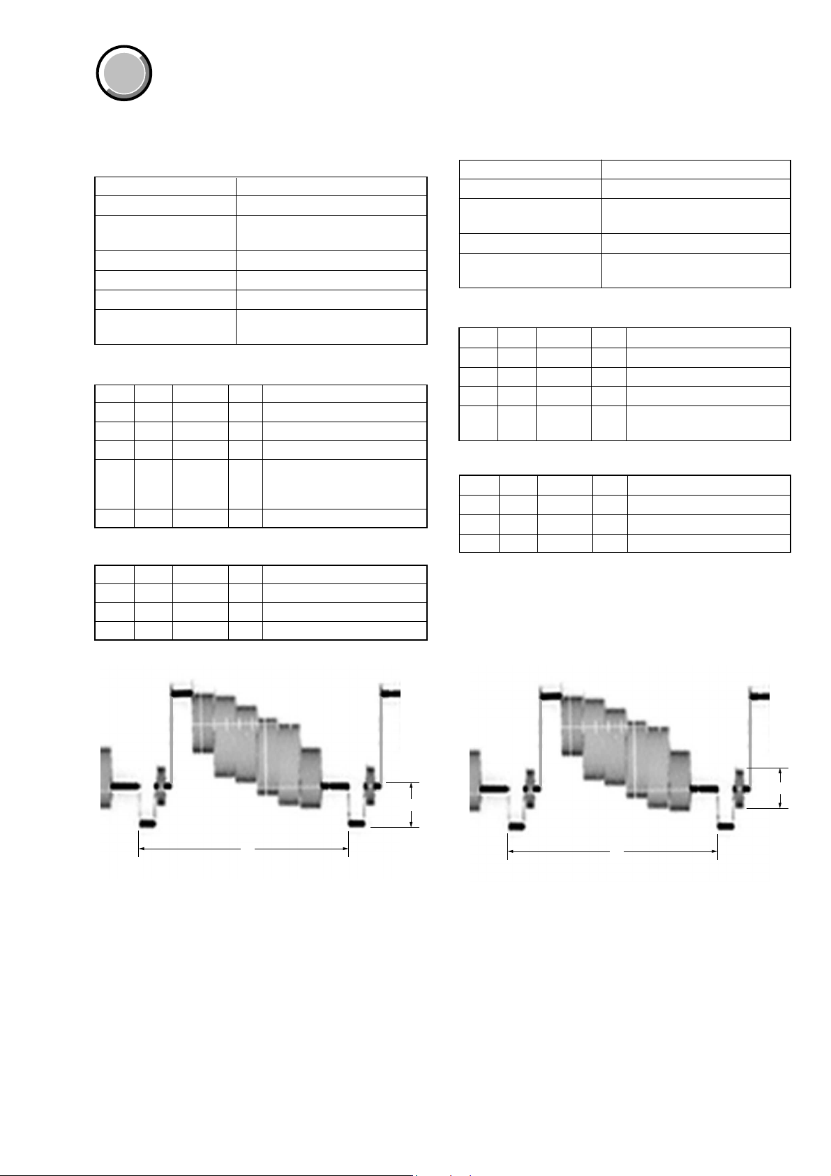
4. Preparing the Flash Adjustment Box
A dark room is required to provide an accurate flash adjustment.
If it is not available, prepare the flash adjustment box as given
below;
1) Provide woody board A, B and C of 15 mm thickness.
Dimensions without brackets are for a box of 1 m in depth.
Dimensions in brackets are for a box of 50 cm in depth.
DSC-F77/FX77
woody board A (2)
530 mm
(400 mm)
1026 mm
(513 mm)
1030 mm
(730 mm)
woody board B (2)
500 mm
(370 mm)
1000 mm
(700 mm)
Fig. 6-1-8
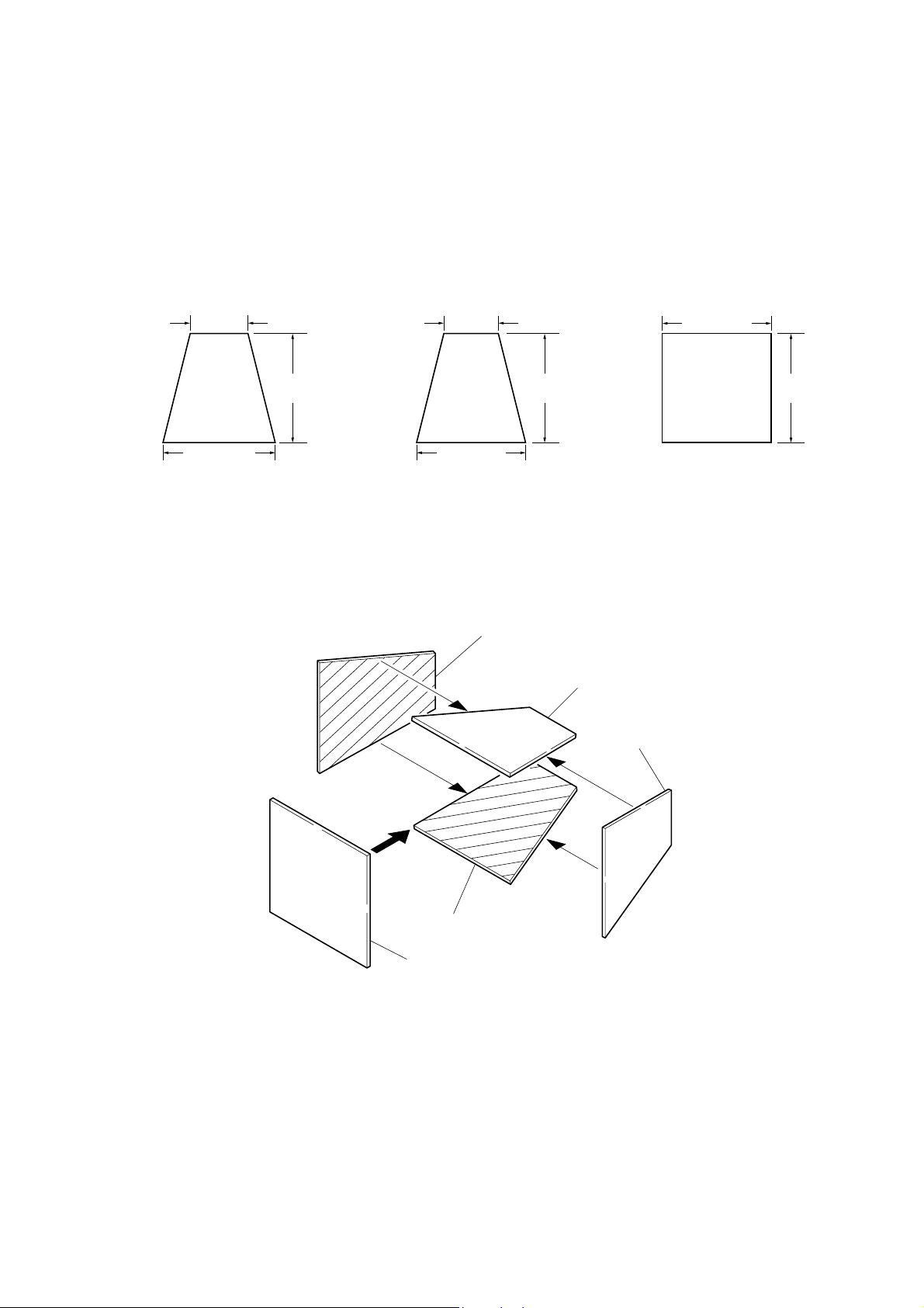
2) Apply black mat paint to one side of woody board A and B.
3) Attach background paper (J-2501-130-A) to woody board C.
4) Assemble so that the black sides and the background paper
side of woody board A, B and C are internal. (Fig 6-1-9)
1026 mm
(513 mm)
woody board A
woody board C (1)
1000 mm
(700 mm)
1000 mm
(700 mm)
woody board B
woody board B
woody board C
Fig. 6-1-9
woody board A
6-7
Page 10
DSC-F77/FX77
COVER
COVER
1-2. INITIALIZATION OF A, B, D, E, F, 7, 9 PAGE
DAT A
1-2-1. Initialization of A, D Page Data
1. Initializing A, D Page Data
Note: If the A, D page data has been initialized, the following
adjustments need to be performed again.
1) Modification of A, D page data
2) Video system adjustments
3) LCD system adjustments
Adjsuting page A
Adjsuting Address 00 to FF
Adjusting page D
Adjusting Address 10 to 7F
Initializing Method:
Order Page Address Data Procedure
10 0101
Set the following data
24 03
34 002D
44 01 2D Press PAUSE button.
54 02 Check the data changes to “01”.
6
2. Modification of A, D Page Data
If the A, D page data has been initialized, change the data of the
“Fixed data-2” address shown in the following table by manual
input.
Modifying Method:
1) Before changing the data, select page: 0, address: 01, and set
data: 01.
2) New data for changing are not shown in the tables because
they are different in destination. When changing the data, copy
the data built in the same model.
Note: If copy the data built in the different model, the
camera may not operate.
3) When changing the data, press the PAUSE button of the
adjusting remote commander each time when setting new data
to write the data in the non-volatile memory.
4) Check that the data of adjustment addresses is the initial v alue.
If not, change the data to the initial value.
10: DSC-F77
0F: DSC-FX77
Perform “Modification of
A, D page Data”.
3. A Page table
Note 1: Fixed data-1: Initialized data.
(Refer to “1. Initializing the A, D Page Data”)
Note 2: Fixed data-2: Modified data.
(Refer to “2. Modification of A, D Page Data”)
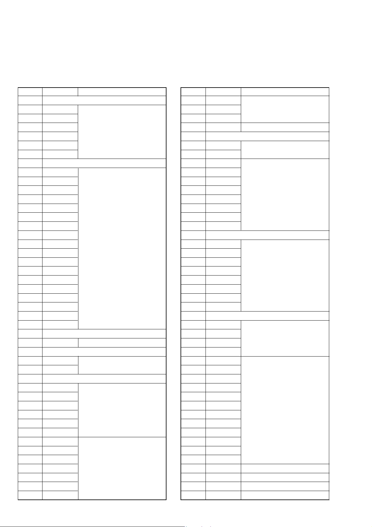
Address Initial value Remark
00 to 4E Fixed data-1 (Initialized data)
4F Fixed data-2
50 to 5A Fixed data-1 (Initialized data)
5B Fixed data-2
5C to 81 Fixed data-1 (Initialized data)
82 80 VCO adj. (NTSC mode)
83 96 VCO adj. (PAL mode)
84 9E V-COM adj.
85 BD Bright adj.
86 Fixed data-1 (Initialized data)
87 38 PSIG level adj.
88 94
89 72
8A 46 Contrast adj.
8B 36 VG center adj.
8C to 9F Fixed data-1 (Initialized data)
A0 80 Video sync level adj.
A1 to A7 Fixed data-1 (Initialized data)
A8
A9
AA to FF Fixed data-1 (Initialized data)
4. D Page table
Note 1: Fixed data-1: Initialized data.
(Refer to “1. Initializing the A, D Page Data”)
Note 2: Fixed data-2: Modified data.
(Refer to “2. Modification of A, D Page Data”)
Address Initial value Remark
10 to 20 Fixed data-1 (Initialized data)
21 00 Test mode
22 to 7F Fixed data-1 (Initialized data)
White balance adj.
Fixed data-2
Processing after Completing Modification of A, D Page Data:
Order Page Address Data Procedure
12 0029
22 01 29 Press PAUSE button.
6-8
Page 11
DSC-F77/FX77
1-2-2. Initialization of B, E, F, 7, 9 Page Data
1. Initializing B, E, F, 7, 9 Page Data
Note: If the B, E, F, 7, 9 Page data has been initialized,
“Modification of B, E, F, 7, 9 Page Data” and following
adjustments need to be performed again.
1) Modification of B, E, F, 7, 9 page data
2) Camera system adjustments
Adjusting page B
Adjusting Address 00 to FF
Adjusting page E
Adjusting Address 00 to FF
Adjusting page F
Adjusting Address 00 to FF
Adjusting page 7
Adjusting Address 00 to FF
Adjusting page 9
Adjusting Address 00 to FF
Initializing Method:
Order Page Address Data Procedure
10 0101
Set the following data
26 03
36 002D
46 01 2D Press PAUSE button.
56 02 Check the data changes to “01”.
6
10: DSC-F77
0F: DSC-FX77
Perform “Modification of B,
E, F, 7, 9 page Data”.
3. B Page Table
Note 1: Fixed data-1: Initialized data.
(Refer to “1. Initializing B, E, F, 7, 9 Page Data”)
Note 2: Fixed data-2: Modified data.
(Refer to “2. Modification of B, E, F, 7, 9 Page Data”)
Address Initial value Remark
00 to FF Fixed data-1 (Initialized data)
4. E Page Table
Note 1: Fixed data-1: Initialized data.
(Refer to “1. Initializing B, E, F, 7, 9 Page Data”)
Note 2: Fixed data-2: Modified data.
(Refer to “2. Modification of B, E, F, 7, 9 Page Data”)
Address Initial value Remark
00 to FF Fixed data-1 (Initialized data)
2. Modification of B, E, F, 7, 9 Page Data
If the B, E, F, 7, 9 Page data has been initialized, change the data
of the “Fixed data-2” address shown in the following tables by
manual input.
Modifying Method:
1) Before changing the data, select page: 0, address: 01, and set
data: 01.
2) New data for changing are not shown in the tables because
they are different in destination. When chang ing the data, copy
the data built in the same model.
Note: If copy the data built in the different model, the
camera may not operate.
3) When changing the data, press the PAUSE button of the
adjusting remote commander each time when setting new data
to write the data in the non-volatile memory.
4) Check that the data of adjustment addresses is the initial v alue.
If not, change the data to the initial value.
Processing after Completing Modification of B, E, F, 7, 9
Page data
Order Page Address Data Procedure
12 0029
22 01 29 Press PAUSE button.
6-9
Page 12
DSC-F77/FX77
5. F Page Table
Note 1: Fixed data-1: Initialized data.
(Refer to “1. Initializing the B, E, F, 7, 9 Page Data”)
Note 2: Fixed data-2: Modified data.
(Refer to “2. Modification of B, E, F, 7, 9 Page Data”)
Address Initial value Remark
00 to 0F Fixed data-1 (Initialized data)
10 FF
11 FF
12 FF
13 FF
14 00
15 90
16, 17 Fixed data-1 (Initialized data)
18 36
19 54
1A 87
1B 71
1C 11
1D 49
1E 00
1F 00
20 00
21 00
22 00
23 00
24 20
25 20
26 BA
27 46
28 0A
29 00
2A to 3D Fixed data-1 (Initialized data)
3E FF Flange back adj.
3F to 51 Fixed data-1 (Initialized data)
52 00
53 00
54 to 57 Fixed data-1 (Initialized data)
58 53
59 3A
5A 20
5B 5B
5C 7D
5D 5D
5E 00
5F 00
60 00
61 00
62 00
63 00
64 00
AF illumination check
Flange back adj.
Flange back adj.
Hall adj.
F No. compensation
Address Initial value Remark
65 30
66 FE
67 6D
68 68 Hall adj.
69 to 6D Fixed data-1 (Initialized data)
6E 00
6F 00
70 29
71 83
72 1F
73 DF
74 29
75 0C
76 22
77 6D
78 to 87 Fixed data-1 (Initialized data)
88 19
89 66
8A 30
8B 6E
8C 19
8D A7
8E 32
8F FB
90 to 9F Fixed data-1 (Initialized data)
A0 29
A1 90
A2 60
A3 80
A4 03
A5 E9
A6 63
A7 83
A8 D5
A9 FE
AA 73
AB 45
AC 63
AD 83
AE 03
AF E9
B0 00 AWB 3200K standard data input
B1 00 AWB 5800K standard data input
B2 00 AWB 3200K standard data input
B3 00 AWB 5800K standard data input
Light value adj.
Mixed color cancel adj.
AWB 3200K standard data input
AWB 5800K standard data input
AWB 5800K standard data input
Color reproduction adj.
6-10
Page 13
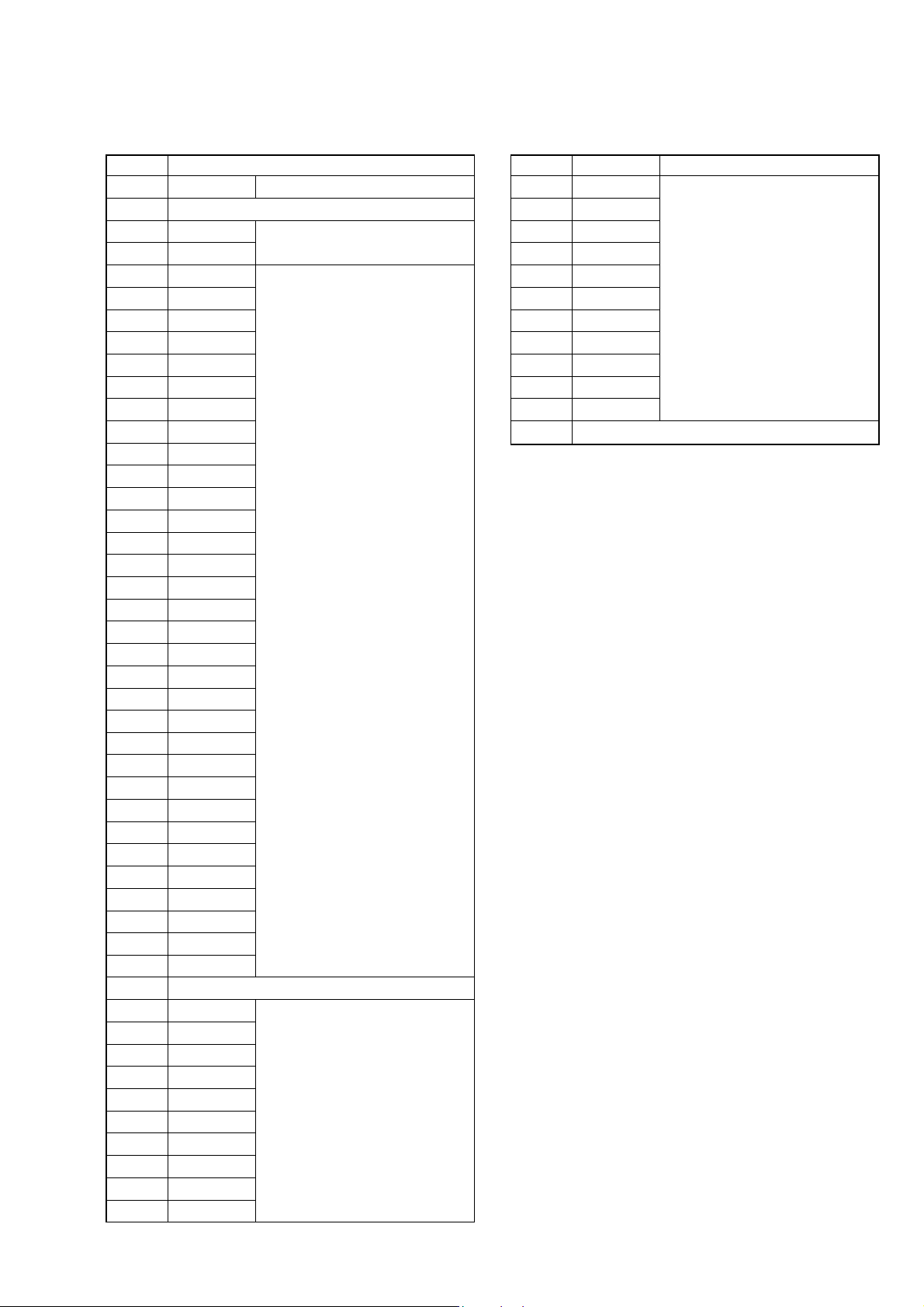
F Page Table
Address Initial value Remark
B4 00 AWB 3200K standard data input
B5 Fixed data-1 (Initialized data)
B6 28
B7 6E
B8 10
B9 6B
BA 0F
BB F6
BC 0F
BD F7
BE 0F
BF F2
C0 0F
C1 F7
C2 00
C3 00
C4 00
C5 00
C6 00
C7 30
C8 1B
C9 12
CA 0D
CB 08
CC 80
CD 88
CE 98
CF 90
D0 88
D1 00
D2 00
D3 00
D4 00
D5 00
D6 00
D7 14
D8 to DA Fixed data-1 (Initialized data)
DB 00
DC 00
DD 00
DE 00
DF 00
E0 00
E1 00
E2 00
E3 00
E4 00
Strobe white balance adj.
Mechanical shutter adj.
Strobe white balance adj.
DSC-F77/FX77
Address Initial value Remark
E5 00
E6 00
E7 00
E8 00
E9 00
EA 00
EB 00
EC 00
ED 00
EE 00
EF 00
F0 to FF Fixed data-1 (Initialized data)
Strobe white balance adj.
6-11
Page 14
DSC-F77/FX77
6. 7 Page Table
Note 1: Fixed data-1: Initialized data.
(Refer to “1. Initializing B, E, F, 7, 9 Page Data”)
Note 2: Fixed data-2: Modified data.
(Refer to “2. Modification of B, E, F, 7, 9 Page Data”)
Address Initial value Remark
00 to FF Fixed data-1 (Initialized data)
7. 9 Page Table
Note 1: Fixed data-1: Initialized data.
(Refer to “1. Initializing B, E, F, 7, 9 Page Data”)
Note 2: Fixed data-2: Modified data.
(Refer to “2. Modification of B, E, F, 7, 9 Page Data”)
Address Initial value Remark
00 to FF Fixed data-1 (Initialized data)
1-2-3. Initialization of Bluetooth (DSC-FX77)
1. Initializing of Bluetooth Revision History
Initializing Method:
Order Page Address Data Procedure
10 0101
25 002D
35 01 2D Press PAUSE button.
45 02 Check the data changes to “01”.
55 0001
65 01 2F Press PAUSE button.
75 02 Check the data changes to “01”.
Check the data (Note)
85 03
90 0100
Note: When the result of this check is “Defective”, try initializ-
ing again. If it keeps failing, SY-81 board may be defective.
2. Checking of Bluetooth Function
Refer to the Bluetooth Function Operating Instructions from page
7 to page 8 (Japanese model: page 10 to page 12) to check that
sending/receiving images can be executed normally.
00: Normal
01: Defective
6-12
Page 15
COVER
COVER
DSC-F77/FX77
1-3. VIDEO SYSTEM ADJUSTMENTS
1. Video Sync Level Adjustment
Adjust the sync level of the composite video signal output.
Mode PLAY
Signal Arbitrary
Measurement Point Video terminal of A/V OUT jack
(75 Ω terminated)
Measuring Instrument Oscilloscope
Adjustment Page A
Adjustment Address A0
Specified Value A = 286 ± 5 mVp-p (NTSC mode)
A = 300 ± 5 mVp-p (PAL mode)
Adjusting method:
Order Page Address Data Procedure
10 0101
2A 02 03 Press PAUSE button
34 F104
Change the data and set the
4A A0
5A A0 Press PAUSE button
Processing after Completing Adjustments:
Order Page Address Data Procedure
1A 02 00 Press PAUSE button
24 F100
30 0100
sync level (A) to the specified
value.
2. Video Burst Level Check
Check the burst level of the composite video signal output.
Mode PLAY
Signal Arbitrary
Measurement Point Video terminal of A/V OUT jack
(75 Ω terminated)
Measuring Instrument Oscilloscope
Specified Value A = 286 ± 30 mVp-p (NTSC mode)
A = 300 ± 30 mVp-p (PAL mode)
Adjusting method:
Order Page Address Data Procedure
10 0101
2A 02 03 Press PAUSE button
34 F104
4
Processing after Completing Adjustments:
Order Page Address Data Procedure
1A 02 00 Press PAUSE button
24 F100
30 0100
Check that the burst level (A)
is satisfied the specified value.
H
Fig. 6-1-10
A
A
H
Fig. 6-1-11
6-13
Page 16

DSC-F77/FX77
COVER
COVER
1-4. CAMERA SYSTEM ADJUSTMENTS
Before perform the camera system adjustments, check that the
specified values of “VIDEO SYSTEM ADJUSTMENTS” are satisfied.
Note: For “CAMERA SYSTEM ADJUSTMENTS”, perform in
order of item numbers.
Data setting during camera system adjustments
Perform the following data setting before the camera system adjustments.
It is not necessary to perform the following data setting ev erytime
when you perform some items of camera system adjustments continuously unless the power is turned off. Only when the power is
turned off during this adjustments, perform the data setting again,
then continue the adjustments.
Set up setting:
1) VIDEO OUT of SET UP setting............... NTSC (NTSC mode)
(This adjustment must be performed in NTSC mode, so don't
set the SET UP setting to “PAL”)
Data setting method:
Order Page Address Data Procedure
10 0101
Set the bit value of bit 5 is
2A 01
32 10
4A 02
5D 21 04 Press PAUSE button.
66 C1
76 6C01
8Wait for 1 second.
97 0A 04 Press PAUSE button.
10 E 96 00 Press PAUSE button.
Note 1:For the bit values, refer to “6-2. SERVICE MODE”,
“2-3. 2. Bit value discrimination”.
Note 2: In case of wrong data.
• Select page: 2, address: 00 and set data: 29.
• Select page: 2, address: 01 and set data: 29.
• Select page: 2, address: 0C, set the bit value of bit 1 is
“1”.
• Select page: 2, address: 04 and set data: 04.
Set the adjusting remote commander to normal LANC,
and the power will be turned, off and on automatically .
Note 3: Repeat the “Data setting method”, if the power was turned
off and on during the “CAMERA SYSTEM ADJUSTMENTS”.
“1”, and press PAUSE
button. (Note 1)
Check the bit values of bit3,
bit4 and bit5 are “1”.
(Note 1, 2)
Set the bit value of bit 1 is
“1”, and press PAUSE
button. (Note 1)
Check the data changes to
“02”.
After completing the camera system adjustments,
release the data setting:
Order Page Address Data Procedure
17 0A 00 Press PAUSE button.
2E 96 40 Press PAUSE button.
36 6C00
4D 21 00 Press PAUSE button.
Set the bit value of bit 1 is
5A 02
6A 01
70 0100
“0”, and press PAUSE
button. (Note 1)
Set the bit value of bit 5 is
“0”, and press PAUSE
button. (Note 1)
6-14
Page 17

DSC-F77/FX77
Color bar chart picture frame
Monitor TV picture frame
E=F
V
EF
Picture Frame Setting
Mode CAMERA
Subject Color bar chart
(Standard picture frame with the
zoom at WIDE end)
Measurement Point Video terminal of A/V OUT jack
(75 Ω terminated)
Measuring Instrument Oscilloscope and monitor TV
Specified Value A=B, C=D, E=F
Note 1: Displayed data of the page 1 of adjusting remote com-
mander.
1:XX:XX
YL data
YH data
Switch setting
1) MACRO (Control button) ..........................ON
Setting method:
Order Page Address Data Procedure
1
Shoot the color bar chart
with the zoom WIDE end.
Enter the output of VIDEO
2
OUT to the monitor TV, and
move the position as shown
in Fig. 6-1-14.
Horizontal width of one color
(B, C) and that of black (A,
3
D) on the color bar chart
should be same. (See Fig. 61-12)
With vertical width of black
(E, F) set in same, the color
4
bar chart should come to the
center of monitor TV. (See
Fig. 6-1-13)
5
Check that the color bar on
the monitor TV is focused.
60 0322
71
Note down the YH and YL
data. (Note 1)
How to reset the zoom and focus when they deviated:
Order Page Address Data Procedure
16 2C01
26 92 YL (Note 2)
36 93 YH (Note 2)
46 01 79 Press PAUSE button.
56 07
Check the data changes to
“01”.
66 01 00 Press PAUSE button.
Note 2: The data noted down at step 7 of “Setting method”.
Check on the oscilloscope
1. Horizontal period
A=B
B
A
C=D
C
D
Fig. 6-1-12
2. Vertical period
Processing after Completing Adjustment:
Order Page Address Data Procedure
10 0300
Fig. 6-1-13
Check on the monitor TV
Fig. 6-1-14
6-15
Page 18

DSC-F77/FX77
RadarW
RadarW
RadarW
RadarW
1. HALL Adjustment
Mode CAMERA
Subject Not required
Adjustment Page F
Adjustment Address 58 to 5D, 68
Note 1: Check that the data of page: 6, address: 02 is “00”.
If not, turn the power of unit OFF/ON.
Adjusting method:
Order Page Address Data Procedure
1
26 016D
36 02
Note 2: The adjustment data will be automatically input to page:
F, address: 58 to 5D, and 68.
RadarW
Perform “Data setting during
camera system adjustment”.
(Refer to page 6-14)
Press PAUSE button.
(Note 2)
Check the data changes to
“01”.
Processing after Completing Adjustment:
Order Page Address Data Procedure
16 01 00 Press PAUSE button.
Release the data setting
2
performed at step 1.
(Refer to page 6-14)
6-16
Page 19

DSC-F77/FX77
2. Flange Back Adjustment
(Using the minipattern box)
RadarWRadarWRadarW
The inner focus lens flange back adjustment is carried out automatically. In whichever case, the focus will be deviated during
auto focusing/manual focusing.
Mode CAMERA
Subject Siemens star chart with ND filter
for minipattern box (Note 1)
Measurement Point Displayed data of page: F,
address: 3E
Measuring Instrument Adjusting remote commander
Adjustment Page F
Adjustment Address 18 to 29, 3E, 52, 53
Specified Value
Date of page: F , Address: 3E is “00”
Note 1: Dark Siemens star chart.
Note 2: Check that the data of page: 6, address: 02 is “00”.
If not, turn the power of unit OFF/ON.
Preparations before adjustments:
1) The minipattern box is installed as shown in the following figure.
Note 3: The attachment lenses are not used.
2) Install the minipattern box so that the distance between it and
the front of lens of camera is less than 3 cm.
3) Make the height of minipattern box and the camera equal.
4) Check the output voltage of the regulated power supply is the
specified voltage ± 0.01 Vdc.
5) Check that the center of Siemens star chart meets the center of
shot image screen.
Adjusting method:
Order Page Address Data Procedure
Perform “Data setting during
1
camera system adjustment”.
(Refer to page 6-14)
26 01 13 Press PAUSE button.
36 0127
46 02
Press PAUSE button.
(Note 4)
Check the data changes to
“01”.
5F 3E Check the data is “00”.
Note 4: The adjustment data will be automatically input to page:
F, address: 18 to 29, 3E, 52 and 53.
Processing after Completing Adjustment:
Order Page Address Data Procedure
16 01 00 Press PAUSE button.
Release the data setting
2
performed at step 1.
(Refer to page 6-14)
3
Perform “Flange Back
Check”.
Specified voltage:The specified voltage varies according to the
minipattern box, so adjustment the power supply output voltage to the specified voltag e written on the sheet which is supplied with the minipattern box.
Below 3 cm
Minipattern box
Camera
Camera
table
Output voltage : Specified voltage ± 0.01 Vdc
Red (+)
Black (–)
Yellow (SENS +)
White (SENS –)
Black (GND)
Regulated power supply
Output current : more than 3.5 A
Need not connected
Fig. 6-1-15
6-17
Page 20

DSC-F77/FX77
RadarW
RadarW
RadarW
RadarW
3. Flange Back Adjustment
(Using the flange back adjustment chart)
The inner focus lens flange back adjustment is carried out automatically. In whichever case, the focus will be deviated during
auto focusing/manual focusing.
Mode CAMERA
Subject Flange back adjustment chart
Measurement Point Displayed data of page: F,
Measuring Instrument Adjusting remote commander
Adjustment Page F
Adjustment Address 18 to 29, 3E, 52, 53
Specified Value
Note 1: Check that the data of page: 6, address: 02 is “00”.
If not, turn the power of unit OFF/ON.
Preparations before adjustments:
1) Place the Flange back adjustment chart 2.0 m from the front
of the lens.
2) Check that the center of Flange back adjustment chart meets
the center of shot image screen.
Adjusting method:
Order Page Address Data Procedure
1
26 01 13 Press PAUSE button.
36 0115
46 02
5F 3E Check the data is “00”.
Note 2: The adjustment data will be automatically input to page:
F, address: 18 to 29, 3E, 52 and 53.
Processing after Completing Adjustment:
Order Page Address Data Procedure
16 01 00 Press PAUSE button.
2
3
RadarW
(2.0 m from the front of lens)
(Luminance: 300 to 400 lux)
address: 3E
Date of page: F, Address: 3E is “00”
Perform “Data setting during
camera system adjustment”.
(Refer to page 6-14)
Press PAUSE button.
(Note 2)
Check the data changes to
“01”.
Release the data setting
performed at step 1.
(Refer to page 6-14)
Perform “Flange Back check”.
4. Flange Back Check
Mode CAMERA
Subject Siemens star
Measurement Point Check operation on monitor TV
Measuring Instrument
Specified value Lens is Focused
Checking method:
Order Page Address Data Procedure
1
2
3
46 9000
56 9100
66 9200
76 93B0
86 01 79 Press PAUSE button.
96 07
10
Processing after Completing Adjustment:
Order Page Address Data Procedure
16 0100
26 9300
3
RadarWRadarWRadarW
(50 cm from the front of the lens)
(Luminance: 200 to 400 lux)
Place the Siemens star 50 cm
from the front of the lens.
To open the IRIS , decrease
the luminous intensity to the
Siemens star up to a point
before noise appear on the
image.
Perform “Data setting during
camera system adjustment”.
(Refer to page 6-14)
Check the data changes to
“01”.
Check that the lens is
focused.
Release the data setting
performed at step 3.
(Refer to page 6-14)
6-18
Page 21

RadarW
RadarW
RadarW
RadarW
RadarW
RadarW
5. F No. Compensation
Compensate the unevenness of the iris meter sensitivity.
Mode CAMERA
Subject Clear chart
Adjustment Page F
Adjustment Address 5E to 64
Note 1: Check that the data of page: 6, address: 02 is “00”.
If not, turn the power of unit OFF/ON.
Adjusting method:
Order Page Address Data Procedure
1
2
36 01BB
46 02
Note 2: The adjustment data will be automatically input to page:
F, address: 5E to 64.
Processing after Completing Adjustment:
Order Page Address Data Procedure
16 01 00 Press PAUSE button.
2
RadarW
(Standard picture frame with the
zoom at WIDE end)
Perform “Data setting during
camera system adjustment”.
(Refer to page 6-14)
Perform “Picture Frame
setting”.
(Refer to page 6-15)
Press PAUSE button.
(Note 2)
Check the data changes to
“01”.
Release the data setting
performed at step 1.
(Refer to page 6-14)
DSC-F77/FX77
RadarW
RadarW
6. Mechanical Shutter Adjustment
Adjust the period which the mechanical shutter is closed, and compensate the exposure.
Mode CAMERA
Subject Clear chart
(Standard picture frame with the
zoom at WIDE end)
Measurement Point Displayed data of page: 6,
address: AB
Measuring Instrument Adjusting remote commander
Adjustment Page F
Adjustment Address B8 to D7
Specified Value
Note 1: Check that the data of page: 6, address: 02 is “00”.
If not, turn the power of unit OFF/ON.
Adjusting method:
Order Page Address Data Procedure
1
2
36 01AD
46 02
56 AB Check the data is “00”.
Note 2: The adjustment data will be automatically input to page:
F, address: B8 to D7.
Processing after Completing Adjustment:
Order Page Address Data Procedure
16 01 00 Press PAUSE button.
2
Date of page: 6, Address: AB is “00”
Perform “Data setting during
camera system adjustment”.
(Refer to page 6-14)
Perform “Picture Frame
setting”.
(Refer to page 6-15)
Press PAUSE button.
(Note 2)
Check the data changes to
“01”.
Release the data setting
performed at step 1.
(Refer to page 6-14)
RadarW
6-19
Page 22

DSC-F77/FX77
RadarW
RadarW
RadarW
RadarW
RadarW
RadarW
7. Light V alue Adjustment
Adjust the standard LV value.
Mode CAMERA
Subject Clear chart
Measurement Point Displayed data of page: 1 (Note
Measuring Instrument Adjusting remote commander
Adjustment Page F
Adjustment Address 65 to 67
Specified Value AE level 1: 0FE0 to 1020
Note 1: Check that the data of page: 6, address: 02 is “00”.
If not, turn the power of unit OFF/ON.
Note 2: The right four digits of the page: 1 displayed data of the
adjusting remote commander.
1:
XX:XX
Adjusting method:
Order Page Address Data Procedure
1
2
36 010D
46 02
50 0306
61
7F 65
Note 3: The adjustment data will be automatically input to page:
F, address: 65 to 67.
RadarW
(Standard picture frame with the
zoom at WIDE end)
2) and page: F, address: 65
AE level 2: 10 to 50
Displayed data
Perform “Data setting during
camera system adjustment”.
(Refer to page 6-14)
Perform “Picture Frame
setting”.
(Refer to page 6-15)
Press PAUSE button.
(Note 3)
Check the data changes to
“01”.
Check that the displayed data
(Note 2) satisfies the AE
level 1 specified value.
Check that the displayed data
satisfies the AE level 2
specified value.
RadarW
RadarW
8. Mixed Color Cancel Adjustment
To perform mixed color cancel adjustment based on data of each
color in color bar.
Mode CAMERA
Subject Color bar chart
(Standard picture frame with the
zoom at WIDE end)
Adjustment Page F
Adjustment Address 6E and 6F
Adjusting method:
Order Page Address Data Procedure
Perform “Data setting during
1
2
36 02 Check the data is “00”.
46 01 D7 Press PAUSE button.
56 01D5
66 02
Note: The adjustment data will be automatically input to page:
F, address: 6E and 6F.
Processing after Completing Adjustment:
Order Page Address Data Procedure
16 01 00 Press PAUSE button.
2
camera system adjustment”.
(Refer to page 6-14)
Perform “Picture Frame
setting”.
(Refer to page 6-15)
Press PAUSE button.
(Note)
Check the data changes to
“01”.
Release the data setting
performed at step 1.
(Refer to page 6-14)
RadarW
Processing after Completing Adjustment:
Order Page Address Data Procedure
16 01 00 Press PAUSE button.
20 0300
Release the data setting
3
performed at step 1.
(Refer to page 6-14)
6-20
Page 23

DSC-F77/FX77
RadarW
RadarW
9. Auto White Balance 3200K Standard Data Input
RadarW
RadarW
RadarW
Adjust the white balance standard data at 3200K.
Mode CAMERA
Subject Clear chart
(Standard picture frame with the
zoom at WIDE end)
Adjustment Page F
Adjustment Address 70 to 77, B0, B2, B4
Adjusting method:
Order Page Address Data Procedure
Perform “Data setting during
1
2
36 B6 Note down the data.
46 B603
57 44 Check the data is “20”.
66 02 Check the data is “00”.
76 3701
86 01 11 Press PAUSE button.
96 38
10 6 01 C1 Press PAUSE button. (Note)
11 6 02
12 6 01 00 Press PAUSE button.
13 6 02 Check the data is “00”.
14 6 37 02
15 6 01 0B Press PAUSE button.
16 6 02
17 6 01 00 Press PAUSE button.
18 6 02 Check the data is “00”.
19 6 37 04
20 6 01 0B Press PAUSE button.
21 6 02
22 6 01 00 Press PAUSE button.
23 6 02 Check the data is “00”.
24 6 37 06
25 6 01 0B Press PAUSE button.
26 6 02
Note: The adjustment data will be automatically input to page:
F, address: 70 to 77, B0, B2 and B4.
camera system adjustment”.
(Refer to page 6-14)
Perform “Picture Frame
setting”. (Refer to page 6-15)
Check the data changes to
“01”.
Check the data changes to
“01”.
Check the data changes to
“01”.
Check the data changes to
“01”.
Check the data changes to
“01”.
Processing after Completing Adjustment:
Order Page Address Data Procedure
16 3700
26 01 00 Press PAUSE button.
36 B6 Set data noted down at step 3.
Release the data setting
4
performed at step 1.
(Refer to page 6-14)
6-21
Page 24

DSC-F77/FX77
10. Auto White Balance 5800K Standard Data Input
RadarWRadarWRadarW
Adjust the white balance standard data at 5800K.
Mode CAMERA
Subject Clear chart
(Standard picture frame with the
zoom at WIDE end)
Filter Filter C14 for color temperature
correction
Adjustment Page F
Adjustment Address 88 to 8F, A0 to A3, B1, B3
Adjusting method:
Order Page Address Data Procedure
1 Place the C14 filter on the
lens.
Perform “Data setting during
2
3
4F A0 29 Press PAUSE button.
5F A1 90 Press PAUSE button.
6F A2 60 Press PAUSE button.
7F A3 80 Press PAUSE button.
86 B6 Note down the data.
96 B603
10 6 02 Check the data is “00”.
11 7 44 10 Press PAUSE button.
12 6 37 07
13 6 01 11 Press PAUSE button.
14 6 38
15 6 01 C3 Press PAUSE button. (Note)
16 6 02
17 7 44 20 Press PAUSE button.
18 6 01 00 Press PAUSE button.
19 6 02 Check the data is “00”.
20 6 37 08
21 6 01 A5 Press PAUSE button.
22 6 02
23 6 01 00 Press PAUSE button.
24 6 02 Check the data is “00”.
25 6 37 0A
26 6 01 A5 Press PAUSE button.
27 6 02
28 6 01 00 Press PAUSE button.
29 6 02 Check the data is “00”.
30 6 37 0C
camera system adjustment”.
(Refer to page 6-14)
Perform “Picture Frame
setting”. (Refer to page 6-15)
Check the data changes to
“01”.
Check the data changes to
“01”.
Check the data changes to
“01”.
Check the data changes to
“01”.
Order Page Address Data Procedure
31 6 01 A5 Press PAUSE button.
32 6 02
Note: The adjustment data will be automatically input to page:
F, address: 88 to 8F, A0 to A3, B1 and B3.
Processing after Completing Adjustment:
Order Page Address Data Procedure
16 3700
26 01 00 Press PAUSE button.
36 B6 Set data noted down at step 8.
4
5
Check the data changes to
“01”.
Release the data setting
performed at step 2.
(Refer to page 6-14)
Remove the C14 filter on the
lens.
6-22
Page 25

RadarW
RadarW
RadarW
RadarW
11. Auto White Balance 5800K Check 1
Mode CAMERA
Subject Clear chart
(Standard picture frame with the
zoom at WIDE end)
Filter Filter C14 for color temperature
correction
Measurement Point Displayed data of Page: 1 (Note)
Measuring Instrument Adjusting remote commander
Specified Value R ratio: 2790 to 2B90
B ratio: 5E80 to 6280
R-Y level data: 007A to 0086
B-Y level data: 007A to 0086
Note: The right four digits of the page: 1 displayed data of the
adjusting remote commander.
1:XX:XX
Displayed data
Checking method:
Order Page Address Data Procedure
1
2
3
46 B6 Note down the data.
56 B603
66 02 Check the data is “00”.
77 44 10 Press PAUSE button.
86 3713
96 01 11 Press PAUSE button.
10 6 38
11 6 01 C3 Press PAUSE button.
12 6 02
13 0 03 04
14 1
15 0 03 05
16 1
17 0 03 2C
18 1
19 0 03 2D
20 1
21 7 44 20 Press PAUSE button.
22 6 01 00 Press PAUSE button.
Place the C14 filter on the
lens.
Perform “Data setting during
camera system adjustment”.
(Refer to page 6-14)
Perform “Picture Frame
setting”. (Refer to page 6-15)
Check the data changes to
“01”.
Check the data changes to
“01”.
Check that the displayed data
(Note) satisfied the R ratio
specified value.
Check that the displayed data
(Note) satisfied the B ratio
specified value.
Check that the R-Y level data
(Note) satisfied the specified
value.
Check that the B-Y level data
(Note) satisfied the specified
value.
RadarW
DSC-F77/FX77
Order Page Address Data Procedure
23 6 02 Check the data is “00”.
24 6 37 14
25 6 01 3F Press PAUSE button.
26 6 02
27 0 03 04
28 1
29 0 03 05
30 1
31 0 03 2E
32 1
33 0 03 2F
34 1
Processing after Completing Adjustment:
Order Page Address Data Procedure
10 0300
26 3700
36 01 00 Press PAUSE button.
46 B6 Set data noted down at step 4.
5
6
Check the data changes to
“01”.
Check that the displayed data
(Note) satisfied the R ratio
specified value.
Check that the displayed data
(Note) satisfied the B ratio
specified value.
Check that the R-Y level data
(Note) satisfied the specified
value.
Check that the B-Y level data
(Note) satisfied the specified
value.
Release the data setting
performed at step 2.
(Refer to page 6-14)
Remove the C14 filter on the
lens.
6-23
Page 26

DSC-F77/FX77
12. Auto White Balance 5800K Check 2
Mode CAMERA
Subject Clear chart
(Standard picture frame with the
zoom at WIDE end)
Filter Filter C14 for color temperature
correction
Measurement Point Displayed data of Page: 1 (Note)
Measuring Instrument Adjusting remote commander
Specified Value R ratio: 2790 to 2B90
B ratio: 5E80 to 6280
R-Y level data: 007A to 0086
B-Y level data: 007A to 0086
Note: The right four digits of the page: 1 displayed data of the
adjusting remote commander.
1:XX:XX
Displayed data
Checking method:
Order Page Address Data Procedure
1
2
3
46 B6 Note down the data.
56 B603
66 02 Check the data is “00”.
76 3716
86 01 3F Press PAUSE button.
96 02
10 0 03 04
11 1
12 0 03 05
13 1
14 0 03 2E
15 1
16 0 03 2F
17 1
Place the C14 filter on the
lens.
Perform “Data setting during
camera system adjustment”.
(Refer to page 6-14)
Perform “Picture Frame
setting”. (Refer to page 6-15)
Check the data changes to
“01”.
Check that the displayed data
(Note) satisfied the R ratio
specified value.
Check that the displayed data
(Note) satisfied the B ratio
specified value.
Check that the R-Y level data
(Note) satisfied the specified
value.
Check that the B-Y level data
(Note) satisfied the specified
value.
RadarWRadarWRadarW
Processing after Completing Adjustment:
Order Page Address Data Procedure
10 0300
26 3700
36 01 00 Press PAUSE button.
46 B6 Set data noted down at step 4.
Release the data setting
5
6
performed at step 2.
(Refer to page 6-14)
Remove the C14 filter on the
lens.
6-24
Page 27

RadarW
RadarW
RadarW
RadarW
13. Auto White Balance 5800K Check 3
Mode CAMERA
Subject Clear chart
(Standard picture frame with the
zoom at WIDE end)
Filter Filter C14 for color temperature
correction
Measurement Point Displayed data of Page: 1 (Note)
Measuring Instrument Adjusting remote commander
Specified Value R ratio: 2790 to 2B90
B ratio: 5E80 to 6280
R-Y level data: 007A to 0086
B-Y level data: 007A to 0086
Note: The right four digits of the page: 1 displayed data of the
adjusting remote commander.
1:XX:XX
Displayed data
Checking method:
Order Page Address Data Procedure
1
2
3
46 B6 Note down the data.
56 B603
66 02 Check the data is “00”.
76 3718
86 01 3F Press PAUSE button.
96 02
10 0 03 04
11 1
12 0 03 05
13 1
14 0 03 2E
15 1
16 0 03 2F
17 1
Place the C14 filter on the
lens.
Perform “Data setting during
camera system adjustment”.
(Refer to page 6-14)
Perform “Picture Frame
setting”. (Refer to page 6-15)
Check the data changes to
“01”.
Check that the displayed data
(Note) satisfied the R ratio
specified value.
Check that the displayed data
(Note) satisfied the B ratio
specified value.
Check that the R-Y level data
(Note) satisfied the specified
value.
Check that the B-Y level data
(Note) satisfied the specified
value.
RadarW
DSC-F77/FX77
Processing after Completing Adjustment:
Order Page Address Data Procedure
10 0300
26 3700
36 01 00 Press PAUSE button.
46 B6 Set data noted down at step 4.
Release the data setting
5
6
performed at step 2.
(Refer to page 6-14)
Remove the C14 filter on the
lens.
6-25
Page 28

DSC-F77/FX77
14. Auto White Balance 3200K Check 1
Mode CAMERA
Subject Clear chart
(Standard picture frame with the
zoom at WIDE end)
Measurement Point Displayed data of Page: 1 (Note)
Measuring Instrument Adjusting remote commander
Specified Value R ratio: 3E00 to 4200
B ratio: 3E00 to 4200
R-Y level data: 007E to 0082
B-Y level data: 007E to 0082
Note: The right four digits of the page: 1 displayed data of the
adjusting remote commander.
1:XX:XX
Displayed data
Checking method:
Order Page Address Data Procedure
Perform “Data setting during
1
2
36 B6 Note down the data.
46 B603
56 02 Check the data is “00”.
67 44 Check the data is “20”.
76 370D
86 01 11 Press PAUSE button.
96 38
10 6 01 C1 Press PAUSE button.
11 6 02
12 0 03 04
13 1
14 0 03 05
15 1
16 0 03 2C
17 1
18 0 03 2D
19 1
20 6 01 00 Press PAUSE button.
21 6 02 Check the data is “00”.
22 6 37 0E
23 6 01 0F Press PAUSE button.
24 6 02
camera system adjustment”.
(Refer to page 6-14)
Perform “Picture Frame
setting”. (Refer to page 6-15)
Check the data changes to
“01”.
Check the data changes to
“01”.
Check that the displayed data
(Note) satisfied the R ratio
specified value.
Check that the displayed data
(Note) satisfied the B ratio
specified value.
Check that the R-Y level data
(Note) satisfied the specified
value.
Check that the B-Y level data
(Note) satisfied the specified
value.
Check the data changes to
“01”.
RadarWRadarWRadarW
Order Page Address Data Procedure
25 0 03 04
Check that the displayed data
26 1
27 0 03 05
28 1
29 0 03 2E
30 1
31 0 03 2F
32 1
Processing after Completing Adjustment:
Order Page Address Data Procedure
10 0300
26 3700
36 01 00 Press PAUSE button.
46 B6 Set data noted down at step 3.
5
(Note) satisfied the R ratio
specified value.
Check that the displayed data
(Note) satisfied the B ratio
specified value.
Check that the R-Y level data
(Note) satisfied the specified
value.
Check that the B-Y level data
(Note) satisfied the specified
value.
Release the data setting
performed at step 1.
(Refer to page 6-14)
6-26
Page 29

RadarW
RadarW
RadarW
RadarW
15. Auto White Balance 3200K Check 2
Mode CAMERA
Subject Clear chart
(Standard picture frame with the
zoom at WIDE end)
Measurement Point Displayed data of Page: 1 (Note)
Measuring Instrument Adjusting remote commander
Specified Value R ratio: 3E00 to 4200
B ratio: 3E00 to 4200
R-Y level data: 007E to 0082
B-Y level data: 007E to 0082
Note: The right four digits of the page: 1 displayed data of the
adjusting remote commander.
1:XX:XX
Displayed data
Checking method:
Order Page Address Data Procedure
Perform “Data setting during
1
2
36 B6 Note down the data.
46 B603
56 02 Check the data is “00”.
66 3710
76 01 0F Press PAUSE button.
86 02
90 0304
10 1
11 0 03 05
12 1
13 0 03 2E
14 1
15 0 03 2F
16 1
camera system adjustment”.
(Refer to page 6-14)
Perform “Picture Frame
setting”. (Refer to page 6-15)
Check the data changes to
“01”.
Check that the displayed data
(Note) satisfied the R ratio
specified value.
Check that the displayed data
(Note) satisfied the B ratio
specified value.
Check that the R-Y level data
(Note) satisfied the specified
value.
Check that the B-Y level data
(Note) satisfied the specified
value.
RadarW
DSC-F77/FX77
Processing after Completing Adjustment:
Order Page Address Data Procedure
10 0300
26 3700
36 01 00 Press PAUSE button.
46 B6 Set data noted down at step 3.
Release the data setting
5
performed at step 1.
(Refer to page 6-14)
6-27
Page 30

DSC-F77/FX77
16. Auto White Balance 3200K Check 3
Mode CAMERA
Subject Clear chart
(Standard picture frame with the
zoom at WIDE end)
Measurement Point Displayed data of Page: 1 (Note)
Measuring Instrument Adjusting remote commander
Specified Value R ratio: 3E00 to 4200
B ratio: 3E00 to 4200
R-Y level data: 007E to 0082
B-Y level data: 007E to 0082
Note: The right four digits of the page: 1 displayed data of the
adjusting remote commander.
1:XX:XX
Displayed data
Checking method:
Order Page Address Data Procedure
Perform “Data setting during
1
2
36 B6 Note down the data.
46 B603
56 02 Check the data is “00”.
66 3712
76 01 0F Press PAUSE button.
86 02
90 0304
10 1
11 0 03 05
12 1
13 0 03 2E
14 1
15 0 03 2F
16 1
camera system adjustment”.
(Refer to page 6-14)
Perform “Picture Frame
setting”. (Refer to page 6-15)
Check the data changes to
“01”.
Check that the displayed data
(Note) satisfied the R ratio
specified value.
Check that the displayed data
(Note) satisfied the B ratio
specified value.
Check that the R-Y level data
(Note) satisfied the specified
value.
Check that the B-Y level data
(Note) satisfied the specified
value.
RadarWRadarWRadarW
Processing after Completing Adjustment:
Order Page Address Data Procedure
10 0300
26 3700
36 01 00 Press PAUSE button.
46 B6 Set data noted down at step 3.
Release the data setting
5
performed at step 1.
(Refer to page 6-14)
6-28
Page 31

RadarW
RadarW
RadarW
R-Y
B-Y
R
B
G
M
G
Y
E
C
Y
Burst position
W
RadarW
17. Color Reproduction Adjustment
Adjust the color separation matrix coefficient so that proper color
reproduction is produced.
Mode CAMERA
Subject Color bar chart
(Standard picture frame with the
zoom at WIDE end)
Measurement Point Video terminal of A/V OUT jack
(75 Ω terminated)
Measuring Instrument Vectorscope
Adjustment Page F
Adjustment Address A4 to AF
Specified Value All color luminance points
should settle within each color
reproduction frame.
Menu setting:
1) VIDEO OUT of SET UP menu
................................ NTSC (NTSC mode)
Adjusting method:
Order Page Address Data Procedure
Perform “Data setting during
1
2
36 02 Check the data is “00”.
4E 96 Check the data is “00”.
56 01 AB Press PAUSE button.
66 1280
7Wait for 1 second.
86 1200
9Wait for 2 seconds.
10 6 37 1F
11 6 01 A9 Press PAUSE button. (Note)
12 6 02
13
Note: The adjustment data will be automatically input to page:
F, address: A4 to AF.
Processing after Completing Adjustment:
Order Page Address Data Procedure
16 3700
26 01 00 Press PAUSE button.
3
camera system adjustment”.
(Refer to page 6-14)
Perform “Picture Frame
Setting”. (Refer to page 6-15)
Check the data changes to
“01”.
Check the each color luminance point is in each color
reproduction frame.
Release the data setting
performed at step 1.
(Refer to page 6-14)
RadarW
DSC-F77/FX77
Fig. 6-1-16
6-29
Page 32

DSC-F77/FX77
RadarW
RadarW
RadarW
RadarW
18. CCD White Defect Compensation
Mode CAMERA
Subject Not required
Measurement Point Displayed data of page: 6,
address: 55
Measuring Instrument Adjusting remote commander
Note 1: Check that the data of page: 6, address: 02 is “00”.
If not, turn the power of unit OFF/ON.
Note 2: The“CCD White Defect Compensation” should be made
when the set warms up at certain duration after the power
was turned on, as it is affected with the temperature.
Adjusting method:
Order Page Address Data Procedure
Perform “Data setting during
1
2E 64 Note down the data.
3E 64 1E Press PAUSE button.
4E 69 Note down the data.
5E 69 0C Press PAUSE button.
66 01 8B Press PAUSE button.
76 02
86 55
96 01 00 Press PAUSE button.
10 E 64 0F Press PAUSE button.
11 E 69 60 Press PAUSE button.
12 6 01 87 Press PAUSE button.
13 6 02
14 6 55
camera system adjustment”.
(Refer to page 6-14)
Check the data changes to
“01”.
Check the data.
00 to 7F: Normal
80 to FF: Defective
Check the data changes to
“01”.
Check the data.
00: Normal
01 to FF: Defective
RadarW
Processing after Completing Adjustment:
Order Page Address Data Procedure
16 01 00 Press PAUSE button.
Set data noted down at step
2, and press PAUSE button.
Set data noted down at step
4, and press PAUSE button.
Release the data setting
performed at step 1.
(Refer to page 6-14)
2E 64
3E 69
4
6-30
Page 33

RadarW
RadarW
RadarW
RadarW
19. CCD Black Defect Compensation
Mode CAMERA
Subject Clear chart
(25 cm from the front of lens)
(Note 3)
Measurement Point Displayed data of page: 6,
address: 55
Measuring Instrument Adjusting remote commander
Note 1: Check that the data of page: 6, address: 02 is “00”.
If not, turn the power of unit OFF/ON.
Note 2: Check that there are no dust, no dirt and reflection of the
clear chart.
Note 3: Any subject other than the clear chart should be in the
screen.
Adjusting method:
Order Page Address Data Procedure
Perform “Data setting during
1
2E 65 Note down the data.
3E 65 4C Press PAUSE button.
46 2C01
56 9200
66 9300
76 01 79 Press PAUSE button.
86 3008
96 07
10 Wait for 4 seconds.
11 6 01 8D Press PAUSE button.
15 6 02
13 6 55
14 6 01 00 Press PAUSE button.
15 E 65 5A Press PAUSE button.
16 6 01 89 Press PAUSE button.
17 6 02
18 6 55
camera system adjustment”.
(Refer to page 6-14)
Check the data changes to
“01”.
Check the data changes to
“01”.
Check the data.
00: Proceed to “Processing
after Completing Adjustment”
01 to 14 : Normal
15 to FF : Defective
Check the data changes to
“01”.
Check the data.
00: Normal
01 to FF: Defective
RadarW
DSC-F77/FX77
Processing after Completing Adjustment:
Order Page Address Data Procedure
16 01 00 Press PAUSE button.
26 2C00
36 3000
4E 65
5
Set data noted down at step
2, and press PAUSE button.
Release the data setting
performed at step 1.
(Refer to page 6-14)
6-31
Page 34

DSC-F77/FX77
RadarW
RadarW
RadarW
RadarW
20. Strobe White Balance Adjustment
Adjust the white balance when the strobe light flashed.
Mode CAMERA
Subject Flash adjustment box (Note 3)
(50 cm from the front of lens)
Measurement Point Displayed data of page: 1 (Note
4) and page: F, address: E8, EA,
EC, EE
Measuring Instrument Adjusting remote commander
Adjustment Page F
Adjustment Address B6, B7, DB to EF
Specified Value Y level data: 03 to 09
R-Y level data:
FA to FF or 00 to 06 (Note 4)
B-Y level data:
FA to FF or 00 to 06 (Note 4)
Note 1: Check that the data of page: 6, address: 02 is “00”.
If not, turn the power of unit OFF/ON.
Note 2: Perform this adjustment in the Flash adjustment box.
Note 3: Refer to “4. Preparing the Flash adjustment box”.
(See page 6-7)
Note 4: The right four digits of the page: 1 displayed data of the
adjusting remote commander.
1:
XX:XX
B-Y level data
R-Y level data
Note 5: “Strobe White Balance Adjustment” is available only
once after the power is turned on. Turn the power off,
then on again if the adjustment is retried.
Switch setting:
1) FLASH (Control button) .............. ON
Adjusting method:
Order Page Address Data Procedure
Perform “Data setting during
1
26 2C01
36 92FF
46 93FF
56 6C01
66 01 79 Press PAUSE button.
76 07
86 01 67 Press PAUSE button.
9 Check the flashing.
10 6 02
11 F E8
12 6 01 00 Press PAUSE button.
13 6 01 67 Press PAUSE button.
14 Check the flashing.
15 6 02
camera system adjustment”.
(Refer to page 6-14)
Check the data changes to
“01”.
Check the data changes to
“01”.
Check that the displayed data
satisfies the Y level data
specified value.
Check the data changes to
“01”.
RadarW
Order Page Address Data Procedure
16 6 01 00 Press PAUSE button.
17 6 01 67 Press PAUSE button.
18 Check the flashing.
19 6 02
20 6 01 00 Press PAUSE button.
21 6 01 67 Press PAUSE button.
22 Check the flashing.
23 6 02
24 6 01 00 Press PAUSE button.
25 6 01 B9 Press PAUSE button. (Note 6)
26 Check the flashing.
27 6 02
28 6 01 00 Press PAUSE button.
29 6 01 E7 Press PAUSE button.
30 Check the flashing.
31 6 02
32 Wait for 1 second.
EA Check that the displayed data
33 F EC satisfies the Y level data
EE specified value.
34 0 03 02
35 1
Note 6: The adjustment data will be automatically input to page:
F, address: B6, B7 and DB to EF.
Processing after Completing Adjustment:
Order Page Address Data Procedure
16 01 00 Press PAUSE button.
26 9200
36 9300
46 2C00
56 6C00
60 0300
7
Check the data changes to
“01”.
Check the data changes to
“01”.
Check the data changes to
“01”.
Check the data changes to
“01”.
Check that the R-Y, B-Y level
data (Note 4) satisfies the
specified value.
Release the data setting
performed at step 1.
(Refer to page 6-14)
6-32
Page 35

DSC-F77/FX77
21. AF Illumination Check
Check the deviation of optical axis of AF illuminator.
Mode CAMERA
Subject Flash adjustment box (Note 3)
Measurement Point Displayed data of page: F,
Measuring Instrument Adjusting remote commander
Adjustment Page F
Adjustment Address 10 to 15
Specified Value
Note 1: Perform checking by making the shooting surface of the
Flash adjustment box perpendicular to the optical axis of
the camera.
Note 2: Perform this checking in the Flash adjustment box.
Restrict external light to enter the Flash adjustment box
as less as possible.
Note 3: Refer to “4. Preparing the Flash adjustment box”.
(See page 6-7)
Adjusting method:
Order Page Address Data Procedure
1
29 A9 Note down the data.
39 A9
46 01 EF Press PAUSE button. (Note 4)
56 02
6F 10 Check the data is “00”.
Note 4: The adjustment data will be automatically input to page:
F, address: 10 to 15.
RadarWRadarWRadarW
(50 cm or 1 m from the front of
lens)
address: 10
Data of page: F , Address: 10 is “00”
Perform “Data setting during
camera system adjustment”.
(Refer to page 6-14)
Set the following data, and
press PAUSE button.
06: 50 cm
04: 1 m
Check the data changes to
“01”.
Processing after Completing Adjustment:
Order Page Address Data Procedure
16 01 00 Press PAUSE button.
29 A9
3
Set data noted down at step
2, and press PUASE button.
Release the data setting
performed at step 1.
(Refer to page 6-14)
6-33
Page 36

DSC-F77/FX77
COVER
COVER
1-5. LCD SYSTEM ADJUSTMENTS
Note 1: Taken an extreme care not to destroy the liquid crystal
display module by static electricity when replacing it.
Note 2: Set the LCD BRIGHTENSS (SET UP setting) to the
NORMAL.
[Measuring points]
Measuring points for LCD system adjustment exsists on SY-81
board.
Adjust it after setting it as service position referring to “ 2. DISASSEMBLY”.
Measuring points are indicated in the figure shown below.
JL704
JL702
JL701
Fig. 6-1-17
6-34
Page 37

DSC-F77/FX77
1. LCD Initial Data Input (1)
Mode PLAY
Signal Arbitrary
Adjustment Page A
Adjustment Address
Adjusting method:
1) Select page: 0, address: 01, and set data: 01.
2) Select page: A, and enter the data given in the follo wing table.
Note: Press the PAUSE button each time the data are set, as the
data are written to non-volatile memory (EEPROM).
Address Data Remark
67 15
68 22
69 21
6A 38
6D 4C Fixed value
6E 4C
6F 4C
80 C4
81 18
82 80 VCO Adjustment (NTSC mode)
83 96 VCO Adjustment (PAL mode)
84 9E V -COM Adjustment
85 BD Bright Adjustment
86 08 Fixed value
87 38 PSIG Level Adjustment
88 94
89 72
8A 46 Contrast Adjustment
8B 36 VG Center Adjustment
8C 2D
8D 2E
8E 80 Fixed value
8F 1F
A3 28
A4 01
67 to 6A, 6D to 6F, 80 to 8F, A3, A4
White Balance Adjustment
2. LCD Initial Data Input (2)
Mode PLAY
Signal Arbitrary
Adjustment Page B
Adjustment Address 3A to 3F
Adjusting method:
1) Select page: 0, address: 01, and set data: 01.
2) Select page: B, and enter the data given in the following table.
Note: Press the PAUSE button each time the data are set, as the
data are written to non-volatile memory (EEPROM).
Address Data Remark
3A 57
3B FE
3C 02
3D 5A
3E 00
3F 01
Processing after Completing Adjustments:
1) Select page: 0, address: 01, and set data: 00.
Fixed data
Processing after Completing Adjustments:
1) Select page: 0, address: 01, and set data: 00.
6-35
Page 38

DSC-F77/FX77
3. VCO Adjustment (SY-81 Board)
Set the VCO free-run frequency. If deviated, the LCD screen will
be blurred.
Mode PLAY
Signal Arbitrary
Measurement Point JL701 of SY-81 board (HDO)
Measuring Instrument Frequency counter
Adjustment Page A
Adjustment Address 82 (NTSC mode)
83 (PAL mode)
Specified Value f = 15734 ± 100 Hz (NTSC mode)
f = 15625 ± 100 Hz (PAL mode)
Menu setting:
1) VIDEO OUT of SET UP setting
......................... NTSC (NTSC mode)
(This adjustment must be performed in NTSC mode, so don’t
set the menu setting to “PAL” )
Adjusting method:
Order Page Address Data Procedure
10 0101
2A 02 03 Press PAUSE button.
34 F113
Change the data and set the
4A 82
5A 82 Press PAUSE button.
64 1D82
7A 83
8A 83 Press PAUSE button.
frequency (f) to the NTSC
specified value.
Change the data and set the
frequency (f) to the PAL
specified value.
4. PSIG Level Adjustment (SY-81 Board)
Set the common electrode drive signal level of LCD to the specified value.
Mode PLAY
Signal Arbitrary
Measurement Point JL702 of SY-81 board (PSIG)
Measuring Instrument Oscilloscope
Adjustment Page A
Adjustment Address 87
Specified Value A = 5.00 ± 0.10 Vp-p
Adjusting method:
Order Page
10 0101
2A 02 03 Press PAUSE button
34 F102
4A 87
5A 87 Press PAUSE button.
Note: Adjust it between data 00 and 7F.
Processing after Completing Adjustment:
Order Page
1A 02 00 Press PAUSE button
24 F100
30 0100
Address
Address
Data Procedure
Change the data and set the PSIG
signal level (A) to the specified
value. (Note)
Data Procedure
Processing after Completing Adjustments:
Order Page Address Data Procedure
1A 02 00 Press PAUSE button.
24 F100
34 1D80
40 0100
A
2H
Fig. 6-1-18
6-36
Page 39

DSC-F77/FX77
2H
A
Pedestal
10 steps peak
A: Between the pedestal and 10 steps peak
5. Bright Adjustment (SY-81 Board)
Set the amplitude of the RGB decoder for driving the LCD to the
specified value.
If deviated, the LCD screen image will be blackish or saturated
(whitish).
Mode PLAY
Signal Arbitrary
Measurement Point JL704 of SY-81 board (VG)
Measuring Instrument Oscilloscope
Adjustment Page A
Adjustment Address 85
Specified Value A = 7.96 ± 0.05 Vp-p
Adjusting method:
Order Page Address Data Procedure
10 0101
2A 02 03 Press PAUSE button
34 F103
Change the data and set the
4A 85
voltage (A) to the specified
value.
5A 85 Press PAUSE button.
Processing after Completing Adjustments:
Order Page Address Data Procedure
1A 02 00 Press PAUSE button
24 F100
30 0100
6. Contrast Adjustment (SY-81 Board)
Set the level of the VIDEO signal for driving the LCD to the specified value.
If deviated, the LCD screen image will be blackish or saturated
(whitish).
Mode PLAY
Signal Arbitrary
Measurement Point JL704 of SY-81 board (VG)
Measuring Instrument Oscilloscope
Adjustment Page A
Adjustment Address 8A
Specified Value A = 2.50 ± 0.05 Vp-p
Adjusting method:
Order Page Address Data Procedure
10 0101
2A 02 03 Press PAUSE button
34 F103
Change the data and set the
4A 8A voltage (A) to the specified
value. (Note)
5A 8A Press PAUSE button.
Note: Adjust it between data 00 and 7F.
Processing after Completing Adjustments:
Order Page Address Data Procedure
1A 02 00 Press PAUSE button
24 F100
30 0100
Pedestal
A
Pedestal
A: Between the reversed waveform pedestal and non-reversed
waveform pedestal
Fig. 6-1-19
2H
Fig. 6-1-20
6-37
Page 40

DSC-F77/FX77
7. VG Center Adjustment (SY-81 Board)
Set the center of VG signal for driving the LCD to the specified
value.
Mode PLAY
Signal Arbitrary
Measurement Point JL704 of SY-81 board (VG)
Measuring Instrument Digital voltmeter
Adjustment Page A
Adjustment Address 8B
Specified Value A = 7.00 ± 0.05 Vdc
Adjusting method:
Order Page Address Data Procedure
10 0101
2A 02 03 Press PAUSE button
34 F102
Change the data and set the
4A 8B DC voltage (A) to the specified
value. (Note)
5A 8B Press PAUSE button.
Note: Adjust it between data 00 and 7F.
Processing after Completing Adjustments:
Order Page Address Data Procedure
1A 02 00 Press PAUSE button
24 F100
30 0100
8. V-COM Adjustment (SY-81 Board)
Set the DC bias of the common electrode drive signal of LCD to
the specified value.
If deviated, the LCD display will be move, producing flicker and
conspicuous vertical lines.
Mode PLAY
Signal Arbitrary
Measurement Point
Measuring Instrument
Check on the LCD screen
Adjustment Page A
Adjustment Address 84
Specified Value The brightness difference
between the section-A and
section-B is minimum
Note 1: Perform “Bright Adjustment” and “Contrast Adjustment”
before this adjustment.
Adjusting method:
Order Page Address Data Procedure
10 0101
2A 02 03 Press PAUSE button
34 F182
Change the data so that
4A 84
brightness of the section A and
section B is equal. (Note 2)
5A 84 Subtract 2 from the data.
6A 84 Press PAUSE button.
Note 2: Adjust it between data 80 and BF.
Processing after Completing Adjustments:
Order Page Address Data Procedure
1A 02 00 Press PAUSE buttton
24 F100
30 0100
A
B
A
B
A
B
A
B
Fig. 6-1-21
6-38
Page 41

9. White Balance Adjustment (SY-81 Board)
Correct the white balance.
If deviated, the LCD screen color cannot be reproduced.
Mode PLAY
Signal Arbitrary
Measurement Point
Measuring Instrument
Adjustment Page A
Adjustment Address 88, 89
Specified Value LCD screen must not be colored
Note 1: Check the white balance only when replacing the fol-
lowing parts. If necessary, adjust them.
1. LCD901 PANEL UNIT
2. IC701
Adjusting method:
Order Page Address Data Procedure
10 0101
2A 02 03 Press PAUSE button
34 F102
4A 88
5A 89
6
7A
Note 2: To write in the non-volatile memory (EEPROM), press
the PAUSE button each time to set the data.
88
89
Check on the LCD screen
Press PAUSE button.
94
(Initial value)
Press PAUSE button.
72
(Initial value)
Check that the LCD screen is
not colored. If not colored,
proceed to “Processing after
Completing Adjustments”.
Change the data so that the
LCD screen is not colored.
(Note 2)
DSC-F77/FX77
Processing after Completing Adjustments:
Order Page Address Data Procedure
1A 02 00 Press PAUSE button
24 F100
30 0100
6-39
Page 42

DSC-F77/FX77
COVER
COVER
6-2. SERVICE MODE
2-1. ADJUSTING REMOTE COMMANDER
The adjusting remote commander is used for changing the calculation coefficient in signal processing, EVR data, etc. The adjusting remote commander performs bi-directional communication
with the unit using the remote commander signal line (LANC).
The resultant data of this bi-directional communication is written
in the non-volatile memory.
1. Used the Adjusting Remote Commander
1) Connect the adjusting remote commander to cradle with LANC
jack (J-6082-548-A).
2) Adjust the HOLD switch of the adjusting remote commander
to “HOLD” (SERVICE position).
3) Turn on the power with the POWER switch of the unit.
If it has been properly connected, the LCD on the adjusting remote commander will display as shown in Fig. 6-2-1.
0 : 00 : 00
Page Data Address
• Changing the address
The address increases when the FF (M) button is pressed,
and decreases when the REW (m) button is pressed. There
are altogether 256 addresses, from 00 to FF.
• Changing the data (Data setting)
The data increases when the PLAY (N) button is pressed,
and decreases when the STOP (x) button is pressed. There
are altogether 256 data, from 00 to FF.
• Writing the adjustment data
The PAUSE button must be pressed to write the adjustment
data in the nonvolatile memory. (The new adjustment data
will not be recorded in the nonvolatile memory if this step is
not performed)
2. Precautions upon Using the Adjusting Remote
Commander
Mishandling of the adjusting remote commander may erase the
correct adjustment data at times. T o prev ent this, it is recommended
that all adjustment data be noted down before beginning adjustments and new adjustment data after each adjustment.
Fig. 6-2-1
4) Operate the adjusting remote commander as follows.
• Changing the page
The page increases when the EDIT SEARCH + button is
pressed, and decreases when the EDIT SEARCH – button is
pressed. There are altogether 16 pages, from 0 to F.
Hexadecimal
notation
LCD Display 01 23456789AbcdEF
Decimal notation
conversion value
0123456789ABCDEF
0123456789101112131415
Table 6-2-1
6-40
Page 43

COVER
COVER
2-2. DATA PROCESS
The calculation of the adjusting remote commander display data
(hexadecimal notation) are required for obtaining the adjustment
data of some adjustment items. In this case, after converting the
hexadecimal notation to decimal notation, calculate and convert
the result to hexadecimal notation, and use it as the adjustment
data. Table 6-2-2. indicates the hexadecimal notation- the decimal notation, calculation table.
DSC-F77/FX77
Hexadecimal nontation-Decimal notation
The lower digits of the 0 1 2 3 4 5 6 7 8 9 A B C D E F
hexadecimal notation
The upper digits of the (A)(b)(c)(d)(E)(F)
hexadecimal notation
0 0123456789101112131415
1 16 17 18 19 20 21 22 23 24 25 26 27 28 29 30 31
2 32 33 34 35 36 37 38 39 40 41 42 43 44 45 46 47
3 48 49 50 51 52 53 54 55 56 57 58 59 60 61 62 63
4 64 65 66 67 68 69 70 71 72 73 74 75 76 77 78 79
5 80 81 82 83 84 85 86 87 88 89 90 91 92 93 94 95
6 96 97 98 99 100 101 102 103 104 105 106 107 108 109 110 111
7 112 113 114 115 116 117 118 119 120 121 122 123 124 125 126 127
8 128 129 130 131 132 133 134 135 136 137 138 139 140 141 142 143
9 144 145 146 147 148 149 150 151 152 153 154 155 156 157 158 159
A (A) 160 161 162 163 164 165 166 167 168 169 170 171 172 173 174 175
1→
B (b) 176 177 178 179 180 181 182 183 184 185 186 187 188 189 190 191
C (c) 192 193 194 195 196 197 198 199 200 201 202 203 204 205 206 207
D (d) 208 209 210 211 212 213 214 215 216 217 218 219 220 221 222 223
E (E) 224 225 226 227 228 229 230 231 232 233 234 235 236 237 238 239
F (F) 240 241 242 243 244 245 246 247 248 249 250 251 252 253 254 255
2
↓
Note : ( ) indicate the adjusting remote control unit display.
(Example) In the case that the adjusting remote control unit display are BD (bd).
As the upper digit of the hexadecimal notation is B (b), and the lower digit is D (d), the intersection “189” of
the1 and 2 in the above table is the decimal notation to be calculated.
Table 6-2-2
6-41
Page 44

DSC-F77/FX77
COVER
COVER
2-3. SERVICE MODE
1. Setting the Test Mode
Page D Address 21
Data Function
00 Normal
01 Forced MOVIE mode power ON
02 Forced SCN mode power ON
03 Forced CAMERA PROGRAM mode power ON
04 Forced CAMERA mode power ON
08 Forced PLAY mode power ON
09 Forced SET UP mode power ON
• Before setting the data, select page: 0, address: 01, and set data:
01.
•For page D, the data set is recorded in the non-volatile memory
by pressing the PAUSE button of the adjusting remote commander. In this case, take note that the test mode will not be
exited even when the main power is turned off.
• After completing adjustments/repairs, be sure to return the data
of this address to “00”, and press the PAUSE button of the adjusting remote commander.
Select page: 0, address: 01, and set data: 00.
2. Bit V alue Discrimination
Bit values must be discriminated using the display data of the adjusting remote commander for following items. Use the table below to discriminate if the bit value is “1” or “0”.
Display on the adjustilng remote commander
0 : 00 : 00
Page
Display on the Bit values
Adjusting bit3 bit2 bit1 bit0
remote or or or or
commander bit7 bit6 bit5 bit4
00000
10001
20010
30011
40100
50101
60110
70111
A
B
Example: If “8E” is displayed on the adjusting remote com-
81000
91001
A (A)1010
B (b)1011
C (c)1100
D (d)1101
E (E)1110
F (F)1111
mander, the bit values for bit7 to bit4 ar e shown in the
A column, and the bit values for bit3 to bit0 are shown
in the B column.
bit3 to bit0 discrimination
bit7 to bit4 discrimination
Address
6-42
Page 45

DSC-F77/FX77
3. Mode Dial Check (1)
Page 2 Address 90
Data Function
00 to 15 MOVIE
16 to 47 SCN
48 to 7E CAMERA PROGRAM
7F to A9 CAMERA
AA to FF others
Using method:
1) Select page: 2, address: 90.
2) By discriminating the bit value of dispaly data, the state of the
switches can be discriminated.
4. Mode Dial Check (2)
Page 2 Address 80, 81
Address Bit Function
80 1 PLAY others PLAY
81 4 SET UP others SET UP
When bit When bit
value=1 value=0
5. Switch Check (1)
Page 2 Address 80
Bit Function
0POWER SW OFF ON
1 PLAY (Mode Dial) others PLAY
2
SHUTTR SW
Control switch block
3
(
S003
XSHUTTER LOCK SW
Control switch block
4
(
S003
MEMORY STICK IN SW
5
(MS Socket)
Using method:
1) Select page: 2, address: 80.
2) By discriminating the bit value of dispaly data, the state of the
switches can be discriminated.
6. Switch Check (2)
Page 2 Address 20
When bit value=1 When bit value=0
OFF ON
)
OFF ON
)
IN OUT
Using method:
1) Select page: 2, address: 80 and 81.
2) By discriminating the bit value of dispaly data, the state of the
switches can be discriminated.
Bit Function
LENS OPEN SW
KK-29 board
2
(
S051
Using method:
1) Select page: 2, address: 20.
2) By discriminating the bit value of dispaly data, the state of the
switches can be discriminated.
7. Switch Check (3)
Page 4 Address D2
Bit Function
LENS REVERSE SW
KK-29 board
5
(
S052
Using method:
1) Select page: 4, address: D2.
2) By discriminating the bit value of dispaly data, the state of the
switches can be discriminated.
)
)
When bit value=1 When bit value=0
OPEN CLOSE
When bit value=1 When bit value=0
REVERSE NORMAL
6-43
Page 46

DSC-F77/FX77
8. Switch Check (4)
Page 2 Address 91 to 94
Using method:
1) Select page: 2, addresses: 91 to 94.
2) By discriminating the dispaly data, the pressed key can be
discriminated.
Address
91
00 to 0C 0D to 27 28 to 48 49 to 73 74 to A5 A6 to DC DD to FF
CONTROL DOWN
CONTROL UP
MENU
Data
LENS REVERSE
LENS NORMAL
(KEY AD0) (SY-81 board) (SY-81 board) (SY-81 board) (KK-29 board) (KK-29 board)
(IC202 tg) (S855) (S855) (S854) (S052) (S052)
92
CONTROL RIGHT
CONTROL LEFT
CONTROL SET
DISPLAY
(KEY AD1) (SY-81 board) (SY-81 board) (SY-81 board) (SY-81 board) No key input
(IC202 th) (S855) (S855) (S855) (S856)
93
BLUETOOTH
*1
(KEY AD2) (BT-14 board) No key input
(IC202 tj) (S101)
94 ZOOM W ZOOM T
(KE1 AD3) (SY-81 board) (SY-81board) No key input
(IC202 tk) (S852) (S853)
*1
: DSC-FX77 only
9. LED Check
Page 2 Address 04 Data 02
Using method:
1) Select page: 2, address: 04, set data: 02, and press PAUSE
button.
2) Check that all LED are lit.
(SELF TIMER/REC, AE/AF LOCK, POWER, CHG, ACCESS
LED)
3) Select page: 2, address: 04, set data: 00, and press PAUSE
button.
10.Self Diagnosis Code
Display Code
C:32:ss
C:13:ss
E:61:ss
E:91:ss
E:92:ss
Turn the power off and on again.
Format the “Memory stick”.
Insert a new “Memory Stick”.
Checking of lens drive circuit.
Checking of flash unit or replacement
of flash unit.
Insert a battery pack correctly. Battery pack is not inserted correctly.
Turn the power off and on again.
Countermeasure
Cause
Trouble with hardware.
Unformatted memory stick is inserted.
Memory stick is broken.
When failed in the focus and zoom
initialization.
Abnormality when flash is being
charged.
Battery pack was installed or removed
when using the AC adaptor.
6-44
Caution Display During Error
SYSTEM ERROR
FORMAT ERROR
MEMORY STICK ERROR
—
Page 47

FOR CAMERA COLOR REPRODUCTION ADJUSTMENT
DSC-F77/FX77
Take a copy of CAMERA COLOR
REPRODUCTION FRAME with a
clear sheet for use.
For NTSC mode
R-Y
M
G
R
Y
E
W
B-Y
B
G
C
Y
✄
DSC-F77/FX77
✄
6-45 E
Page 48

Reverse
992999751.pdf
Revision History
Ver.
1.0
Date
2002.10
History
Official Release
Contents
—
S.M. Rev.
issued
—
 Loading...