

Sony DSR-2000, DSR-2000P, DSBK-190, DSBK-200 Service Manual
DIGITAL VIDEOCASSETTE RECORDER
DSR-2000
DSR-2000P
i.LINK/DV INPUT/OUTPUT BOARD
DSBK-190
REMOTE CONTROL PANEL
DSBK-200
SERVICE MANUAL
Volume 1 1st Edition (Revised 1)

! WARNING
This manual is intended for qualified service personnel only.
To reduce the risk of electric shock, fire or injury, do not perform any servicing other than that
contained in the operating instructions unless you are qualified to do so. Refer all servicing to
qualified service personnel.
! WARNUNG
Die Anleitung ist nur für qualifiziertes Fachpersonal bestimmt.
Alle Wartungsarbeiten dürfen nur von qualifiziertem Fachpersonal ausgeführt werden. Um die
Gefahr eines elektrischen Schlages, Feuergefahr und Verletzungen zu vermeiden, sind bei
Wartungsarbeiten strikt die Angaben in der Anleitung zu befolgen. Andere als die angegeben
Wartungsarbeiten dürfen nur von Personen ausgeführt werden, die eine spezielle Befähigung
dazu besitzen.
! AVERTISSEMENT
Ce manual est destiné uniquement aux personnes compétentes en charge de l’entretien. Afin
de réduire les risques de décharge électrique, d’incendie ou de blessure n’effectuer que les
réparations indiquées dans le mode d’emploi à moins d’être qualifié pour en effectuer d’autres.
Pour toute réparation faire appel à une personne compétente uniquement.
DSR-2000/2000P

CAUTION
ADVARSEL
Danger of explosion if battery is incorrectly replaced.
Replace only with the same or equivalent type
recommended by the manufacturer.
Dispose of used batteries according to the
manufacturer’s instructions.
Vorsicht!
Explosionsgefahr bei unsachgemäßem Austausch
der Batterie.
Ersatz nur durch denselben oder einen vom
Hersteller empfohlenen ähnlichen T yp . Entsorgung
gebrauchter Batterien nach Angaben des
Herstellers.
ATTENTION
Il y a danger d’explosion s’il y a remplacement
incorrect de la batterie.
Remplacer uniquement avec une batterie du même
type ou d’un type équivalent recommandé par le
constructeur.
Mettre au rebut les batteries usagées conformément
aux instructions du fabricant.
Lithiumbatteri - Eksplosjonsfare.
Ved utskifting benyttes kun batteri som
anbefalt av apparatfabrikanten.
Brukt batteri returneres
apparatleverandøren.
VARNING
Explosionsfara vid felaktigt batteribyte.
Använd samma batterityp eller en likvärdig typ
som rekommenderas av apparattillverkaren.
Kassera använt batteri enligt gällande
föreskrifter.
VAROITUS
Paristo voi räjähtää jos se on virheellisesti
asennettu.
Vaihda paristo ainoastaan laitevalmistajan
suosittelemaan tyyppiin.
Hävitä käytetty paristo valmistajan ohjeiden
mukaisesti.
Levér det brugte batteri tilbage til leverandøren.
DSR-2000/2000P
ADVARSEL!
Lithiumbatteri-Eksplosionsfare ved fejlagtig
håndtering.
Udskiftning må kun ske med batteri
af samme fabrikat og type.
1 (P)

Für Kunden in Deutschland
Voor de klanten in Nederland
Entsorgungshinweis: Bitte werfen Sie nur entladene
Batterien in die Sammelboxen beim Handel oder den
Kommunen. Entladen sind Batterien in der Regel dann,
wenn das Gerät abschaltet und signalisiert “Batterie
leer” oder nach längerer Gebrauchsdauer der Batterien
“nicht mehr einwandfrei funktioniert”. Um
sicherzugehen, kleben Sie die Batteriepole z.B. mit
einem Klebestreifen ab oder geben Sie die Batterien
einzeln in einen Plastikbeutel.
Dit apparaat bevat een MnO
2-Li batterij voor memory
back-up.
Raadpleeg uw leverancier over de verwijdering van de
batterij op het moment dat u het apparaat bij einde
levensduur afdankt.
Gooi de batterij niet weg. maar lever hem in als KCA.
Bij dit produkt zijn batterijen geleverd.
Wanneer deze leeg zijn, moet u ze niet
weggooien maar inleveren als KCA.
2 (P)
DSR-2000/2000P

Table of Contents
Manual Structure
Purpose of this manual .............................................................................................. 7
Related manuals......................................................................................................... 7
Contents ..................................................................................................................... 8
1. Operating Instructions
1-1. DSR-2000 ....................................................................................................1-1
1-2. DSBK-190 .................................................................................................1-81
1-3. DSBK-200 .................................................................................................1-86
2. Installation
2-1. Installation Procedure..................................................................................2-1
2-2. Operational Environment ............................................................................2-1
2-3. Operating Voltage .......................................................................................2-1
2-4. Installation Space ........................................................................................2-2
2-5. Supplied Accessories ..................................................................................2-2
2-6. Optional Accessories ...................................................................................2-2
2-7. Rack Mounting ............................................................................................2-3
2-8. Connectors...................................................................................................2-5
2-8-1. Connectors/Cables......................................................................2-5
2-8-2. Input/Output Signals of the Connectors.....................................2-6
2-9. Installation Setup and Adjustment ............................................................2-10
2-9-1. Switch Settings on the Connector Panel ..................................2-10
2-9-2. Front Panel Setting...................................................................2-11
2-9-3. On-board Switch Setting ..........................................................2-12
2-9-4. System Adjustment After Installation......................................2-14
DSR-2000/2000P
3. Service Overview
3-1. Location of Main Parts ................................................................................3-1
3-1-1. Location of Printed Circuit Boards ............................................3-1
3-1-2. Location of Main Mechanical Parts ........................................... 3-6
3-1-3. Location of Sensors....................................................................3-7
3-2. Functions of Record Proof Hole and Record Proof Plug of Cassette .........3-9
3-3. Removal/Installation of Cabinet ...............................................................3-10
3-4. Removal/Reattachment of the Cassette Compartment ..............................3-13
1

3-5. Removal/Reattachment of the Boards .......................................................3-14
3-5-1. Removal/Reattachment of the Card Boards .............................3-14
3-5-2. Extension Board .......................................................................3-14
3-5-3. Removal/Reattachment of the Boards ......................................3-15
3-6. Notes on Repair Parts ................................................................................3-32
3-6-1. Flexible Card Wire Replacement .............................................3-32
3-7. Replacement of Lithium Battery ............................................................... 3-35
3-8. Fixtures and Tools list ............................................................................... 3-36
3-9. Upgrading the System/Servo CPU Program Version ............................... 3-38
3-9-1. Version Upgrade using the DJ-376 ..........................................3-38
3-9-2. Version Upgrade from a PC through RS-422 .......................... 3-39
4. Error Messages
4-1. Alarm Display .............................................................................................4-1
4-1-1. Alarm Display when the Main Power is Turned On .................. 4-1
4-2. Error Codes ................................................................................................. 4-3
4-2-1. Display of Previously Detected Error Codes ............................. 4-5
4-2-2. Main Codes and Sub Codes ....................................................... 4-6
4-2-3. Error Codes ................................................................................ 4-8
4-2-4. Possible Causes of Errors ......................................................... 4-14
4-3. Countermeasure in an Emergency ............................................................4-16
4-3-1. How to Take Out the Cassette Whose Tape is Slacked
(MANUAL EJECT) ................................................................. 4-16
4-3-2. Head Cleaning when Head Clogging Occurs...........................4-17
4-3-3. Operating the VTR without A Cassette Tape ..........................4-17
5. Maintenance Menu
5-1. Menu Structure ............................................................................................5-1
5-2. How to Operate Maintenance Menu ...........................................................5-3
5-2-1. Location and Function of Switches ............................................ 5-3
5-2-2. How to Enter the Maintenance Menu ........................................5-3
5-2-3. How to Exit the Maintenance Menu ..........................................5-3
5-3. Contents of Maintenance Menu ..................................................................5-4
5-3-1. Menu Data Control .....................................................................5-4
5-3-2. Servo Check ............................................................................... 5-7
5-3-3. Servo Adjust ............................................................................. 5-21
5-3-4. Tape Path Adjust ......................................................................5-28
5-3-5. Electrical Adjust ....................................................................... 5-29
5-3-6. Service Support ........................................................................5-38
5-3-7. Others .......................................................................................5-40
2
DSR-2000/2000P

6. Periodic Inspection and Maintenance
6-1. Periodic Inspection List...............................................................................6-1
6-2. Hours Meter ................................................................................................6-2
6-3. Maintenance upon Completion of Repair ...................................................6-4
6-3-1. Video Head Cleaning Procedure ................................................6-4
6-3-3. Cassette Compartment Entrance Cleaning.................................6-5
6-3-4. Cassette Compartment Shaft Cleaning.......................................6-5
6-3-5. Cassette Guide Assembly Cleaning ...........................................6-5
7. Replacement of Mechanical Parts
7-1. General Information on Parts Replacement and Adjustment ......................7-1
7-1-1. Preparation Before Starting Parts Replacement.........................7-1
7-1-2. Drum Assembly .........................................................................7-1
7-1-3. Grease......................................................................................... 7-1
7-1-4. Tightening Torque and Handling of Washers ............................7-2
7-2. Drum Replacement......................................................................................7-3
7-3. S/T Brake Assembly Replacement..............................................................7-8
7-4. Brake Solenoid Replacement ....................................................................7-12
7-5. Pinch Roller Replacement .........................................................................7-17
7-6. Elevator Cam Replacement .......................................................................7-19
7-7. Pinch Solenoid Assembly Replacement....................................................7-21
7-8. Reel Motor (T) Assembly Replacement ...................................................7-23
7-9. Reel Motor (S) Assembly Replacement ....................................................7-27
7-10. M Stop Solenoid Assembly Replacement.................................................7-31
7-11. S Tension Regulator Assembly Replacement ...........................................7-34
7-12. T Drawer Arm Assembly Replacement .................................................... 7-37
7-13. TG1 Arm Assembly Replacement ............................................................7-39
7-14. TG8 Arm Assembly Replacement ............................................................7-41
7-15. Rail Assembly Replacement .....................................................................7-43
7-16. Capstan Motor Replacement .....................................................................7-49
7-17. Loading Motor Replacement.....................................................................7-51
7-18. Reel Shift Motor Assembly Replacement.................................................7-52
7-19. MIC Assembly Replacement ....................................................................7-54
7-20. MIC Holder Assembly Replacement ........................................................7-58
7-21. HC Roller Assembly Replacement ...........................................................7-60
7-22. Head Cleaner Solenoid Replacement........................................................7-63
7-23. Cassette Compartment Motor Replacement..............................................7-65
7-24. Switching Regulator Replacement............................................................7-67
DSR-2000/2000P
3

8. Tape Path Alignment
8-1. General Information for Tape Path Adjustment..........................................8-1
8-2. Tape Path Adjustment .................................................................................8-6
8-3. RF Switching Position Adjustment ............................................................. 8-9
8-4. Tape Path Adjustment Confirmation ........................................................8-12
8-5. Search Forward (x5) Waveform Check....................................................8-13
8-6. Search Reverse (x5) Waveform Check ....................................................8-14
8-7. RF Waveform Raiseup Check ...................................................................8-15
8-8. Tape Curl Check at Tape Guide ................................................................8-16
9. Adjustment When Replacing Board
9-1. Adjustment/Check Items When Replacing Board ...................................... 9-1
10. Electrical Alignment
10-1. Electrical Alignment Overview.................................................................10-1
10-1-1. List of Adjustment Parts........................................................... 10-1
10-1-2. Measuring Equipment and Tools .............................................10-2
10-1-3. Reference Tape for Alignment.................................................10-2
10-2. Audio Adjustment ..................................................................................... 10-4
10-2-1. Audio OUTPUT Level Adjustment .........................................10-4
10-2-2. Audio EE Level Adjustment .................................................... 10-4
10-3. Video Adjustment .....................................................................................10-5
10-3-1. INT SC Frequency Adjustment................................................10-6
10-3-2. HCK Frequency Adjustment....................................................10-6
10-3-3. COMPONENT Y OUT Level Adjustment .............................. 10-7
10-3-4. COMPONENT B-Y OUT Level Adjustment .......................... 10-7
10-3-5. COMPONENT R-Y OUT Level Adjustment .......................... 10-8
10-3-6. SETUP OFF Chroma Level Check (NTSC only) .................... 10-8
10-3-7. S VIDEO OUT Y Level Check................................................10-9
10-3-8. VIDEO OUT 1 Video/Sync Level Adjustment .......................10-9
10-3-9. VIDEO OUT 2 Video Level Check ....................................... 10-10
10-3-10. VIDEO OUT 3 Y Level Adjustment .....................................10-10
10-3-11. ENC SC Leak Adjustment ..................................................... 10-11
10-3-12. U-V Axis (B-Y, R-Y) Phase Adjustment ...............................10-12
10-3-13. PB VIDEO OUT 1 Chroma/Burst Level Adjustment ............ 10-13
10-3-14. PB S VIDEO Chroma Level Adjustment ...............................10-15
10-3-15. PB COMPOSITE C/C Delay Adjustment ..............................10-15
10-3-16. PB COMPOSITE Y/C Delay Adjustment .............................10-16
10-3-17. PB COMPONENT Y/C Delay Adjustment ...........................10-17
10-3-18. PB INT SCH Phase Adjustment ............................................10-18
10-3-19. REF. VIDEO OUT Sync/Burst Level Adjustment ................ 10-19
4
DSR-2000/2000P

10-3-20. REF. INT SCH Phase Adjustment.........................................10-20
10-3-21. SPCK Error Adjustment.........................................................10-21
10-3-22. COMPOSITE 4Fsc PLL DC Check/Adjustment...................10-22
10-3-23. REC Y Clamp Level Adjustment...........................................10-23
10-3-24. REC Y Level Adjustment ......................................................10-24
10-3-25. REC COMPONENT R-Y Level Adjustment ........................10-25
10-3-26. REC COMPONENT B-Y Level Adjustment ........................10-25
10-3-27. REC A/D Y Level Adjustment ..............................................10-26
10-3-28. REC COMPOSITE Y Level Adjustment...............................10-27
10-3-29. REC COMPOSITE Chroma Level Adjustment.....................10-28
10-3-30. REC S VIDEO Chroma Level Adjustment............................10-29
10-3-31. REC COMPOSITE Y/C Delay Adjustment ..........................10-30
10-3-32. REC COMPONENT Y/C Delay Adjustment ........................ 10-31
10-3-33. REC S VIDEO Y/C Delay Adjustment .................................10-32
10-4. SDI/SDTI ................................................................................................10-33
10-4-1. Free Run Adjustment .............................................................10-33
DSR-2000/2000P
5


Purpose of this manual
Related manuals
Manual Structure
This manual is the Service Manual Volume 1 for the digital videocassette recorder
DSR-2000/2000P, the option boards i.LINK/DV Input/Output Board DSBK-190 and
optional Remote Control Panel DSBK-200.
This manual contains the maintenance information of this equipment, and servicing
information necessary for parts replacement and adjustments.
In addition to this Service Manual Volume 1, the following manuals are provided.
..
. Operation Instructions
..
DSR-2000/2000P (Supplied with equipment)
Part number:3-867-754-12 (English; for UC, CE)
3-867-754-22 (French; for UC, CE)
3-867-754-32 (German; for CE)
3-867-754-42 (Italian; for CE)
DSBK-190 (Supplied with Model DSBK-190)
Part number:3-203-674-01
DSBK-200 (Supplied with Model DSBK-200)
Part number:3-203-675-01
DSBK-210 (Supplied with Model DSBK-210)
Part number:3-205-213-01 (1)
..
. Service Manual Volume 2 (Not Supplied with equipment)
..
Contains the semiconductor pin assingnments, parts lists, block diagrams, board
layouts and schematic diagrams.
Part number:9-955-186-22
..
. DSBK-210
..
Service Manual (Not Supplied with equipment)
Contains the maintenance information of the DSBK-210, and servicing information necessary for parts replacement and adjustments.
Part number:9-955-268-01
..
. “Semiconductor Pin Assignments” CD-ROM (Available on request)
..
This “Semiconductor Pin Assignments” CD-ROM allows you to search for
semiconductors used in B&P Company equipment.
Semiconductors that cannot be searched for on this CD-ROM are listed in the
service manual for the corresponding unit. The service manual contains a complete list of all semiconductors and their ID Nos., and thus should be used together
with the CD-ROM.
Part number: 9-968-546-XX
DSR-2000/2000P
7

Contents
The following is a summary of all the sections for understanding the contents of
this manual.
Section 1 Operating Instruction
Describes the contents of the operating instructions.
Section 2 Installation
This section is described in Installation Manual.
Section 3 Service Overview
Describes the replacement of the parts, the locations of the main parts and boards,
notes and so on.
Section 4 Error Messages
Describes the alarms and countermeasures to be displayed when the unit detects
abnormality.
Section 5 Maintenance Menu
Describes the maintenance menu.
Section 6 Periodic Inspection and Maintenance
Describes the periodic inspection and cleaning procedure.
Section 7 Replacement of Mechanical Parts
Describes the replacement procedures and adjustment after replacement.
Section 8 Tape Path Alignment
Describes the adjustment procedures of tape path system.
Section 9 Electrical Alignment After Replacement Boards
Describes the electrical adjustments after replacement boards.
Section 10 Electrical Alignment
Describes the electrical adjustment of each board.
8
DSR-2000/2000P
DSR-2000/2000P
Digital
Videocassette
Recorder
3-867-754-12(1)
DSR-2000/2000P
Operating Instructions
Before operating the unit, please read this manual
thoroughly and retain it for future reference.
1999 by Sony Corporation
1-1. DSR-2000
Operating Instructions
1-1
Section 1
This section is extracted
from operation manual.
1-1. DSR-2000
1-2
Table of Contents
2
Table of Contents
For customers in the USA
This equipment has been tested and found to comply with
the limits for a Class A digital device, pursuant to Part 15 of
the FCC Rules. These limits are designed to provide
reasonable protection against harmful interference when the
equipment is operated in a commercial environment. This
equipment generates, uses, and can radiate radio frequency
energy and, if not installed and used in accordance with the
instruction manual, may cause harmful interference to radio
communications. Operation of this equipment in a residential
area is likely to cause harmful interference in which case the
user will be required to correct the interference at his own
expense.
You are cautioned that any changes or modifications not
expressly approved in this manual could void your authority
to operate this equipment.
The shielded interface cable recommended in this manual
must be used with this equipment in order to comply with the
limits for a digital device pursuant to Subpart B of Part 15 of
FCC Rules.
Caution
Television programs, films, video tapes and other materials
may be copyrighted.
Unauthorized recording of such material may be contrary to
the provisions of the copyright laws.
For the customers in Europe (DSR-2000P only)
This product with the CE marking complies with both the
EMC Directive (89/336/EEC) and the Low Voltage Directive
(73/23/EEC) issued by the Commission of the European
Community.
Compliance with these directives implies conformity to the
following European standards:
• EN60065: Product Safety
• EN55103-1: Electromagnetic Interference (Emission)
• EN55103-2: Electromagnetic Susceptibility (Immunity)
This product is intended for use in the following
Electromagnetic Environment(s):
E1 (residential), E2 (commercial and light industrial), E3
(urban outdoors) and E4 (controlled EMC environment, ex.
TV studio).
Owner’s Record
The model and serial numbers are located in the rear.
Record these numbers in the spaces provided below. Refer
to them whenever you call upon your Sony dealer regarding
this product.
Model No.
Serial No.
WARNING
To prevent fire or shock hazard, do not
expose the unit to rain or moisture.
This symbol is intended to alert the user to the
presence of uninsulated “dangerous voltage”
within the product’s enclosure that may be of
sufficient magnitude to constitute a risk of
electric shock to persons.
This symbol is intended to alert the user to the
presence of important operating and
maintenance (servicing) instructions in the
literature accompanying the appliance.
Table of Contents
3
Table of Contents
Chapter 1
Overview
Features............................................................................. 7
System Configuration .................................................... 11
Location and Function of Parts..................................... 12
Upper Control Panel.............................................................13
Lower Control Panel ............................................................16
Subsidiary Control Panel .....................................................25
Connector Panel ...................................................................28
Usable Cassettes............................................................ 33
Inserting and Ejecting Cassettes ..........................................34
Chapter 2
Setting/Displaying
Time Data and Text
Information
Displaying Time Data and Unit’s Operating Status—
Superimposing Text Information ............................ 35
Setting Time Code and User Bits.................................. 39
Synchronizing the Internal Time Code Generator With an
External Signal—External Lock ..................................... 42
Chapter 3
Recording and
Playback
Recording........................................................................ 45
Preparations for Recording ..................................................45
Recording Time Code and User Bit Values..........................47
Recording Operation ............................................................ 48
Playback .......................................................................... 49
Preparations for Playback ....................................................49
Playback Operation .............................................................. 50
Dynamic Motion Control (DMC) Playback......................... 55
Synchronous Playback .........................................................59
Digitally Dubbing Signals in DVCAM Format
(Optional DSBK-190 Required When Using i.LINK
Interface) ...........................................................................
61
1-1. DSR-2000
DSR-2000/2000P

DSR-2000/2000P
Table of Contents
4
Table of Contents
Chapter 4
Editing
Automatic Editing........................................................... 67
Overview of Automatic Editing ...........................................67
Button/Switch Settings for Editing ......................................70
Selecting an Edit Mode ........................................................ 71
Setting Edit Points................................................................72
Checking Edit Points............................................................75
Modifying Edit Points..........................................................76
Cuing Up to Edit Points .......................................................78
Checking Edit Results
—Preview
.........................................80
Executing Automatic Editing ...............................................81
DMC Editing .................................................................... 84
Overview of DMC Editing...................................................84
Carrying Out DMC Editing.................................................. 85
Preread Editing ............................................................... 87
Special Editing Methods ................................................ 89
Quick Editing .......................................................................90
Continuous Editing ..............................................................91
Standalone Editing ...............................................................93
Manual Editing.....................................................................94
Adding a Narration (Sound-on-Sound)................................95
Table of Contents
5
Chapter 5
ClipLink Operation
Overview of ClipLink Operation .................................... 97
Displaying ClipLink Log Data........................................ 98
Detailed Data Display ..........................................................98
Cuing Up to Mark IN/OUT and Cue Points.................... 99
Cuing Up to Any Desired Position....................................... 99
Cuing Up to Adjacent Mark IN/Cue Points ......................... 99
Rewriting ClipLink Log Data........................................ 100
Changing the Reel Number................................................100
Changing Mark IN/OUT Points.........................................100
Changing the OK/NG Status..............................................101
Adding to/Deleting From ClipLink Log Data .............. 103
Adding Mark IN/OUT Points ............................................103
Deleting Mark IN/OUT Points...........................................103
Automatically Creating New ClipLink Log Data......... 105
Chapter 6
Setup Menu
Menu System Configuration........................................ 107
Basic Menu.................................................................... 107
Items in the Basic Menu..................................................... 107
Basic Menu Operations......................................................110
Extended Menu ............................................................. 113
Items in the Extended Menu ..............................................113
Extended Menu Operations................................................123
1-3
1-1. DSR-2000

1-4
Table of Contents
6
Table of Contents
Chapter 7
Connections and
Settings
Reference Video Signals for Analog Signal Editing .. 125
Connections for Cut Editing Using i.LINK Interface
(Optional DSBK-190 Required) ......................................
125
Connections for Digital Nonlinear Editing Using SDTI
(QSDI) Interface ...................................................... 127
Connections for Cut Editing Using SDI Interface...... 128
Connections for Preread Editing ................................ 129
Settings Required When Connecting an External
Editing Control Unit................................................ 130
Time Code Settings on This Unit.......................................130
Settings on Editing Control Units ......................................130
Connections for Component Analog Recording ....... 131
Connections for Two-Unit Synchronous Playback.... 132
Connections for Digitally Dubbing Signals in DVCAM
Format
(Optional DSBK-190 Required When Using
i.LINK Interface) ..............................................................
133
Chapter 8
Maintenance and
Troubleshooting
Condensation................................................................ 135
Head Cleaning............................................................... 135
Periodic Maintenance................................................... 136
Troubleshooting ............................................................ 137
Error Messages...................................................................139
Alarm Messages.................................................................139
Appendixes
Notes on Use................................................................. 143
Specifications ............................................................... 144
ClipLink
TM
Guide ........................................................... 147
What is ClipLink? ..............................................................147
Example System Configuration and Operation Flow ........148
Data Generated When Shooting.........................................149
Glossary ........................................................................ 152
Index .............................................................................. 155
Chapter 1 Overview
Chapter 1 Overview
7
Chapter
1
Overview
Features
The DSR-2000/2000P is a
1
/
4
-inch digital videocassette
recorder using the DVCAM
TM
digital recording format.
It uses a component video system, with separate
luminance and chrominance signals and digital
processing to realize a stable, high image quality.
This unit is equipped with a variety of functions
needed for videocassette recorders and players used in
video editing. By combining two units, you can easily
assemble a cut editing system. It is also equipped with
full-fledged analog and digital interfaces to support
hybrid systems that combine conventional analog
equipment with digital equipment. Furthermore, it
supports the Sony-developed ClipLink
TM
function,
improving operating efficiency when combined with a
Sony EditStation
TM
.
The following are the principal features of the unit.
DVCAM Format
DVCAM is a professional
1
/4-inch digital recording
format developed by Sony from the consumer DV
component digital format (4:1:1 for DSR-2000/4:2:0
for DSR-2000P).
High image quality and high stability
The luminance and chrominance signals are encoded
separately, with a
1
/
5
compression, giving a stable high
quality video image.
Since this is a digital system, nth-generation copies
created by repeated dubbing show virtually no loss in
picture quality.
Wide track
The recording track width is 15 µm, 50% wider than
the 10 µm of the DV format. This ensures adequate
reliability for professional use.
PCM digital audio for high sound quality
The PCM encoding method yields a high audio
quality, with wide dynamic range and high signal-tonoise ratio.
There are two recording modes: two-channel mode
(48-kHz sampling and 16-bit quantization), which
offers sound quality equivalent to the DAT (Digital
Audio Tape) format, or four-channel (32-kHz
sampling and 12-bit quantization).
Playback compatibility with DV and
DVCPRO formats
A DV cassette recorded on a DV format VCR as well
as a DVCPRO(25M) format recorded cassette can be
played back on this unit.
Note
When playing back a tape recorded in DVCPRO
(25M) format, the SDTI and i.LINK outputs (see the
section “Digital interfaces” on the next page) of this
unit are muted. Furthermore, it is not possible to
playback the cue-audio track of the tape.
1-1. DSR-2000
DSR-2000/2000P

DSR-2000/2000P
Location and Function of Parts
Chapter 1 Overview
8
Chapter 1 Overview
Support for three cassette sizes
There are two sizes of DVCAM cassette: standard and
mini. You can use either size with this unit.
The unit also accepts L and M sizes of DVCPRO
cassette.
•The reel mechanism automatically adjusts to the size
of cassette inserted.
•The capacity of a standard cassette is 184 minutes of
recording/playback, and that of a mini cassette is 40
minutes.
Variety of Interfaces
Digital interfaces
The unit can use the following digital interfaces.
• SDTI (QSDI)
1)
This interface allows video, audio and time code
signals in SDTI (QSDI) format to be transferred at
normal speed between this unit and the ES-7
EditStation. When this unit is connected to another
DVCAM VCR, it is possible to copy compressed
signals between the two VCRs.
• SDI
2)
This interface allows the unit to input or output D1
(component) digital video and audio signals.
• AES/EBU
This interface allows the unit to input or output
digital audio signals in AES/EBU format.
• i.LINK (DV)
3)
(Optional DSBK-190 i.LINK/DV
Input/Output Board)
When the unit is fitted with the optional DSBK-190
i.LINK/DV Input/Output Board using i.LINK
technology, it can input and output digital video and
audio signals in DV format.
•SDTI-CP output (Optional DSBK-210 SDTI-CP
Output Board)
This interface allows the unit to provide an output of
I-frame pictures only (50/40/30 Mbps) complying to
MPEG2 4:2:2 Profile @Main Level. You can connect
the unit to an MPEG supporting device equipped with
an SDTI-CP input.
Note
You cannot install both of the DSBK-190 and DSBK210 on the unit at a time.
Analog interfaces
A wide range of analog interfaces is provided,
allowing this unit to be connected to various video and
audio devices.
•Analog video: Composite, component and S-video
interfaces are provided.
•Analog audio: There are four input channels and
four output channels. There is also support for
microphone input.
Connection to external control devices
It is possible to connect a PVE-500, RM-450/450CE,
FXE-100/100P/120/120P, BVE-900/910/2000/9000/
9000P/9100/9100P or other editor equipped with an
RS-422A interface, or a UVR-60/60P remote
controller for the built-in digital video processor, and
so forth.
Full Functionality for More
Efficient Editing
This unit has a number of functions which assist in
efficient and precise editing.
With two DSR-2000/2000P units together, you can
carry out automatic or manual editing, using either
assemble or insert editing.
The system also provides a powerful range of
functions for setting and amending edit points,
preview, review, and other aspects of efficient editing.
DMC (dynamic motion control) editing
You can save a varying speed, in the range −1 to +1
times normal speed
4)
, for an editing segment, and
automatically edit with this varying speed.
1) SDTI (QSDI): SDTI (Serial Data Transport Interface) is
the name of a standard interface established as SMPTE
305M.
This unit uses SDTI to transmit DV data, and the input/
output connectors are labled
“SDTI(QSDI)”.
In indicator and menu indications, however, the
“SDTI(QSDI)” name is shortened to
“SDTI”.
...............................................................................................................................
..........................................................
2) SDI: Serial Digital Interface is used for transferring video
signals in component digital format (D1).
3)
is a trademark of Sony Corporation and indicates that
this product is in agreement with IEEE1394-1995
specifications and their revisions.
4) The positive direction refers to forward movement of the
tape, and the negative direction to reverse movement.
Features
Chapter 1 Overview
Chapter 1 Overview
9
Split editing
In insert editing, this allows the audio IN and OUT
points to be set separately from the video IN and OUT
points.
Preread editing
The audio or video on the tape can be read out using
the preread heads. The signals then can be processed
and rerecorded where they have been.
Cross-fade editing
For audio editing, you can select from cut-in editing,
fade-in/fade-out editing, and cross-fade editing.
Support for ClipLink function
This unit accepts instructions from an EditStation, to
transfer to the EditStation ClipLink log data held in the
cassette memory or index pictures recorded on the
tape. On the EditStation you can use these images and
data to carry out editing operations efficiently.
•Displaying ClipLink log data
•Changing ClipLink log data OK/NG status
•Cuing up to Mark IN and cue points provided by
ClipLink log data
•For cut editing, copying Mark IN data from ClipLink
log data
For an overview of the ClipLink function, see the appendix
“ClipLink Guide” (page 147).
Internal time code generator and reader
An internal timecode generator and reader enables
timecode compliant with SMPTE/EBU format to be
recorded and played back. This allows editing to single
frame precision.
Outputting or inputting timecode (LTC) to or from an
external device is also possible using the TIME CODE
IN/OUT connectors.
The unit is also compatible with VITC.
High-speed search function
You can carry out a picture search while playing back
in color within the range +60 to
–60 times normal
speed.
When controlling the unit in shuttle mode from an
editor or remote control unit, you can search at any
speed in the range +60 to
–60 times normal speed. In
jog mode a frame by frame search is possible. During
playback in the range +10 to
–10 times normal speed,
high-speed audio playback is also possible.
Digital slow motion playback
Using the frame memory function, noiseless slow
motion playback is possible at any speed in the range
+1 to –1 times normal speed.
Digital jog sound function
When searching at speeds in the range +1 to +
1
/
30
or
–
1
/
30
to –1 times normal speed, the digital jog sound
function is enabled. The audio signal is saved in
temporary memory, and replayed according to the
search speed. This allows searching on the sound
track.
Video process control
For analog video output and SDI-format video output,
you can adjust the video output level, chroma signal
output level, setup level (for DSR-2000), black level
(for DSR-2000P), and chroma phase.
1-5
1-1. DSR-2000

1-6
Location and Function of Parts
Chapter 1 Overview
10
Chapter 1 Overview
Features
Other Features
Menu operations for functions and
operating settings
To make it easier to use this unit for any particular
purpose, various functions and operating settings are
provided in the menu system.
Superimposing function
Timecode, operating mode, error messages, and other
text information, can be superimposed on the SDI
video signal and analog composite video signal output.
Functions for easy maintenance
•Self-diagnosis and alarm function: This
automatically detects incorrect operations or
connections, operating faults, and so forth, and
displays details of the problem, the cause, and the
action to be taken, in the control panel display
section.
•Digital hours meter: This keeps four cumulative
counts of the powered on time, the drum rotation
time, the tape transport time, and the number of tape
threadings and unthreadings, and displays them in the
control panal display section.
Compatible with wide screen aspect ratio
(16:9)
The unit can record and play back aspect ratio
information. When video accompanied by wide-screen
aspect ratio information is recorded or played back, the
unit can output the video signal also containing the
aspect ratio information.
Rack mountable
Using the optional RMM-130 Rack Mount Kit, you
can mount the unit in an EIA standard 19-inch rack
(height: 4 units).
Options
DSBK-190 i.LINK/DV Input/Output Board
This board enables cut editing between two DSR2000/2000P units. It also allows you to connect the
unit to other equipment provided with a Sony DV
connector to carry out editing or dubbing of digital
video and audio signals.
DSBK-200 Control Panel
When connected to the unit, you can operate the unit
remotely from the DSBK-200.
RMM-130 Rack Mount Kit
This kit can be used to mount the unit in an EIAstandard 19-inch rack.
DSBK-210 SDTI-CP Output Board
This board enables the unit to be connected to an
MPEG supporting device (MSW-2000, MAV-555, and
so on).
Chapter 1 Overview
Chapter 1 Overview
11
System Configuration
The figure below shows example equipment that can
be connected to this unit.
i.LINK
(DSBK-190)
a)
i.LINK
(DSBK-190)
a)
SDI INPUT/OUTPUT
COMPONENT
VIDEO IN/OUT
ANALOG VIDEO I/O
S VIDEO IN/OUT
SDTI(QSDI)
INPUT/OUTPUT
SDTI(QSDI)
INPUT/OUTPUT
DVCAM camcorder
DVCAM cassette
DV camcorder
DV cassette
DSR-500WS/500WSP
SVO-5800/5800P
Microphone
Headphones
DSR-2000/2000P (this unit)
DNW-A75/A75P
DSR-60/60P/80/80P/85/85P
Digital VCR
ES-7/ES-3 Edit Station
Analog Betacam VCR
Video monitor
Audio monitor system
DV camcorder
a) The DSBK-190 is an optional board.
1-1. DSR-2000
DSR-2000/2000P
DSR-2000/2000P
Location and Function of Parts
Chapter 1 Overview
12
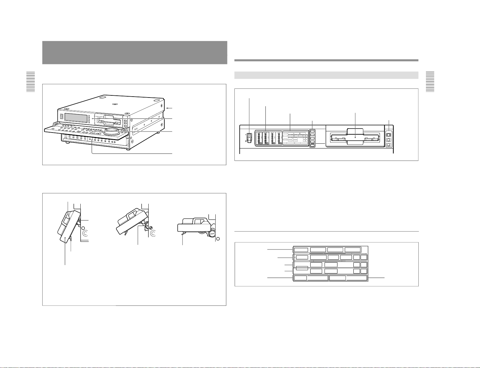
Chapter 1 Overview
Location and Function of Parts
There are four control panels as shown in the figure
below.
Connector panel
(See page 28.)
Upper control panel
(See page 13.)
Lower control panel
(See page 16.)
Subsidiary control panel
(See page 25.)
To adjust the position of the lower control
panel
You can fix the lower control panel in any position
between vertical and horizontal for ease of operation.
Handle
Lock knob
Release lever
Raise the panel by holding both ends or
both handles.
When the panel is at the desired angle,
turn both lock knobs to fix in position.
If you raise the panel to the horizontal, it
automatically locks in position.
To lower the panel, press both
release levers.
To fix the panel at an angle where the lock knobs are inaccessible
1 First position the panel at the desired angle, then without tightening the lock knobs, press the release levers
and raise the panel to the horizontal.
2 With the panel horizontal, tighten the lock knobs, then press the release levers and return the panel to the
desired position, where it will lock into place.
Chapter 1 Overview
Chapter 1 Overview
13
POWER
INPUT SELECT
SDTI/i.LINK
VIDEO IN
REMOTE
9PIN
i.LINK
CH-1,1/2
CH-2,3/4
MIXING
0
2
1
0
-1
-2
-12
dB
OVER
dB
-20
-30
-40
-60
1
0
2
1
0
-1
-2
-12
dB
OVER
dB
-20
-30
-40
-60
2
0
2
1
0
-1
-2
-12
dB
OVER
dB
-20
-30
-40
-60
3
0
2
1
0
-1
-2
-12
dB
OVER
dB
-20
-30
-40
-60
4
INPUT
V:SDTI
COMPOSITE
ANALOG
AES/EBU
ANALOG
SDTI
SDI SG
SDI SG
AES/EBU
SDI SG
Y-R,B
S VIDEO
i.LINK
PB FS
48k44.1k32k
REC MODE
2CH4CH
VIDEO
AUDIO
CH11/2
CH23/4
INPUT
V:SDTI
COMPOSITE
ANALOG
AES/EBU
ANALOG
SDTI
SDI SG
SDI SG
AES/EBU
SDI SG
Y-R,B
S VIDEO
i.LINK
PB FS
48k44.1k32k
REC MODE
2CH4CH
VIDEO
AUDIO
CH11/2
CH23/4
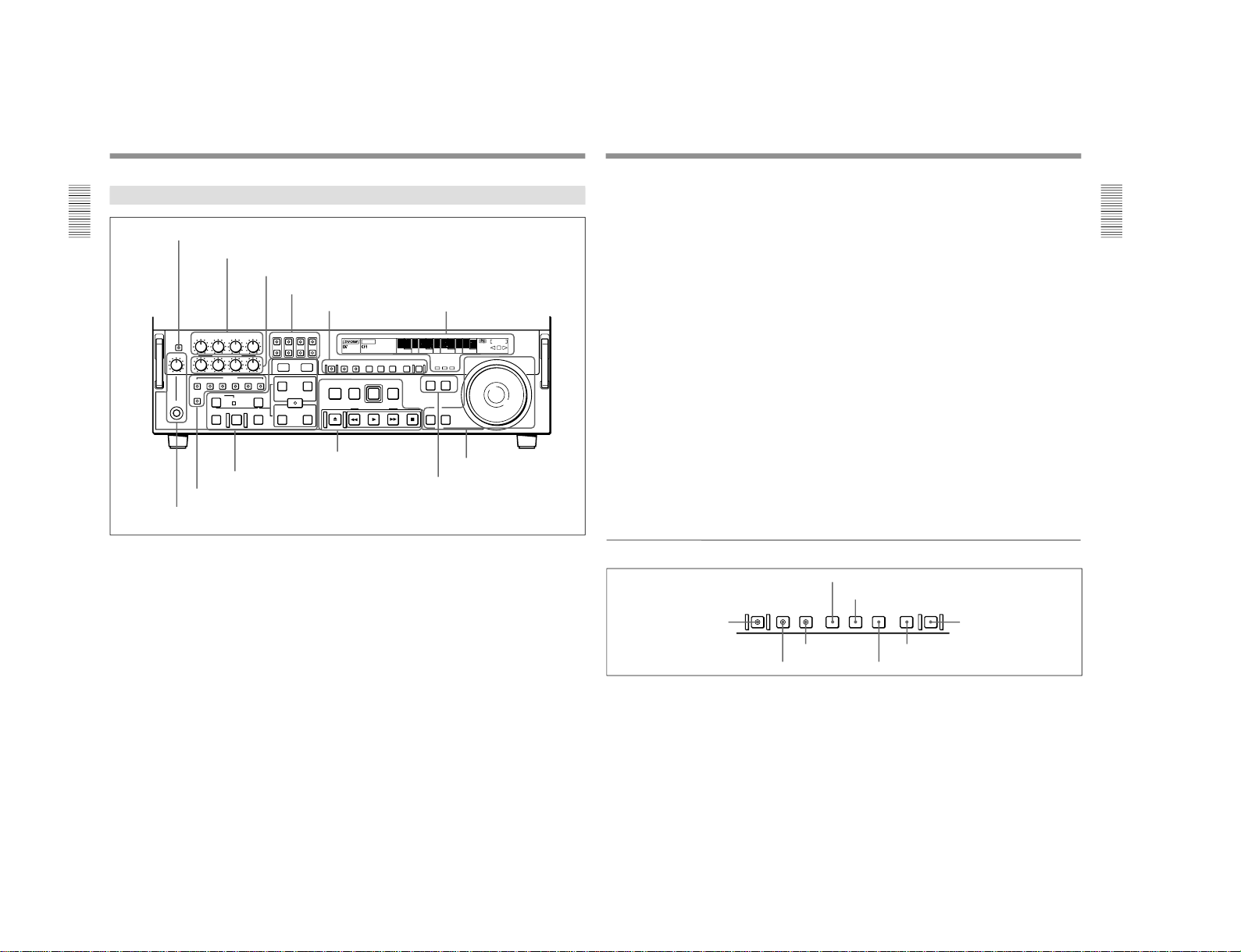
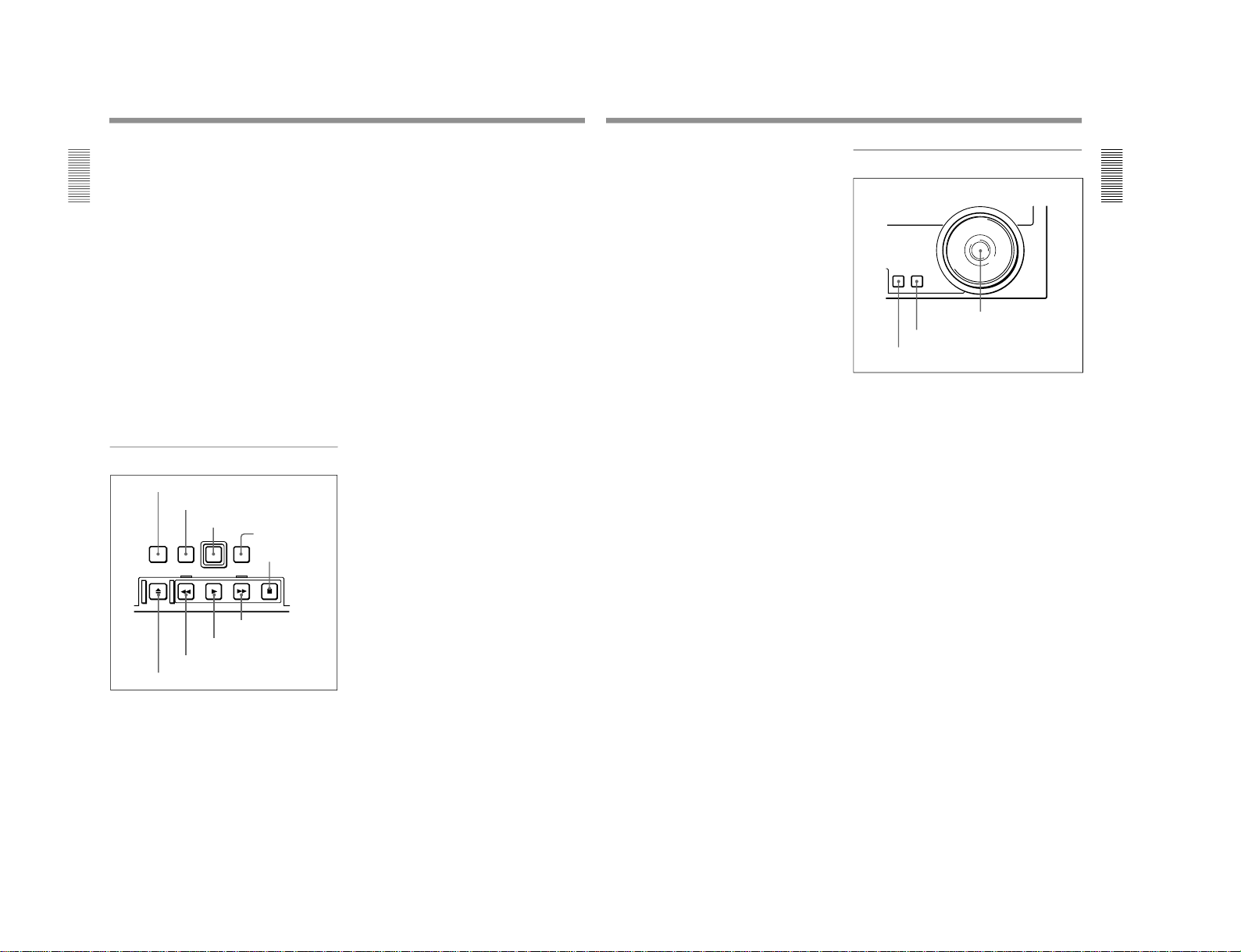
Upper Control Panel
1 POWER switch
2 Audio level meters
3 Cassette compartment
1 Input selection/audio mode display section
(see below)
1 POWER switch
Press the “1” side to power the unit on. When the unit
is powered on, the display windows in the upper and
lower control panels light.
To power the unit off, press the
“
¬”side of the switch.
2 Audio level meters
These show the audio levels of channels 1 to 4
(recording levels in recording mode or E-E mode
1)
and
playback level in playback mode).
There are two modes for audio level indications:
FULL and FINE, selected by the METER FULL/FINE
button on the lower control panel.
1) E-E mode: Abbreviation of
“Electric-to-Electric mode
”.
In this mode, video and audio signals input to the VCR
are output after passing through internal electric circuits,
...............................................................................................................................
..........................................................
3 Cassette compartment
Accepts DVCAM, DV and DVCPRO(25)
videocassettes.
For details of usable cassettes, see page 33.
1 Input selection/audio mode display section
1 INPUT display
5 PB FS display
6 REC MODE display
2 INPUT VIDEO display
3 AUDIO CH1, 1/2 display
4 AUDIO CH2, 3/4 display
but not through magnetic conversion circuits such as
heads and tapes. This can be used to check input signals
and for adjusting input signal levels.
2 Input selection section
(see page 14)
3 Remote control
setting section
(see page 15)
1-7
1-1. DSR-2000
1-8
Location and Function of Parts
Chapter 1 Overview
14
Chapter 1 Overview
1 INPUT display
Indicates the input signal selected with the SDTI/
i.LINK button in the input selection section.
V:SDTI: Digital video signal in SDTI(QSDI) format
In this mode, you can select any audio input,
though the video signal is recorded with a delay of
two frames with respect to the audio input.
SDTI: Digital video and audio signals in
SDTI(QSDI) format
i.LINK: Digital video and audio signals in DV
format, using i.LINK technology
2 INPUT VIDEO display
Indicates the input video signal selected with the
VIDEO IN button in the input selection section.
COMPOSITE: Composite video signal
Y-R, B: Y, R−Y and B−Y component video signals
S VIDEO: S-video signal
SDI: SDI video signal
SG: Video test signal
3 AUDIO CH1, 1/2 display
Indicates the input audio signal selected with the CH1,
1/2 button in the input selection section.
ANALOG: Analog audio signal
AES/EBU: Digital audio signal in AES/EBU format
SDI: SDI audio signal
SG: Audio test signal
4 AUDIO CH2, 3/4 display
Indicates the input audio signal selected with the CH2,
3/4 button in the input selection section. The
indications available are the same as for the AUDIO
CH1, 1/2 display described above.
5 PB FS (playback audio sampling frequency)
display
Indicates the sampling frequency (48 kHz, 44.1 kHz or
32 kHz) at which audio is recorded on tape.
6 REC MODE (audio recording mode) display
Indicates the audio recording mode (2CH or 4CH)
selected with extended menu item 818.
2 Input selection section
1 SDTI/i.LINK (SDTI(QSDI) interface/i.LINK
selection) button
Each press of this button cycles through the following
input signal selection options.
•Digital video signal in SDTI(QSDI) format input to
the SDTI(QSDI) INPUT connector
When this is selected, use the CH1, 1/2 button and
CH2, 3/4 button to select the required input audio
signals.
•Digital video and audio signals in SDTI(QSDI)
format input to the SDTI(QSDI) INPUT connector
•Digital video and audio signals in DV format, using
i.LINK technology, input to the i.LINK connector
(available when the optional DSBK-190 i.LINK/DV
Input/Output Board is installed)
In the input selection/audio mode display section, the
INPUT display shows the selection made with this
button.
2 VIDEO IN button
Each press of this button cycles through the following
input video signal selection options.
•Composite video signal input to the VIDEO IN
connectors.
•Component video signals input to the COMPONENT
VIDEO Y/R−Y/B−Y IN connectors
•S-video signal input to the S VIDEO IN connector
•SDI video signal input to the SDI INPUT connector
•Video test signal (selected with extended menu item
710) generated by the internal signal generator
In the input selection/audio mode display section, the
INPUT VIDEO display shows the selection made with
this button.
INPUT SELECT
SDTI/i.LINK
VIDEO IN
CH-1,1/2
CH-2,3/4
MIXING
3 CH1, 1/2 button
4 CH2, 3/4 button
5 MIXING button
1 SDTI/i.LINK button
2 VIDEO IN button
Chapter 1 Overview
Chapter 1 Overview
15
3 CH1, 1/2 (audio channel 1 or 1/2) button
Each press of this button cycles through the following
input audio signal selection options for audio channel 1
(when in 2-channel mode) or for audio channels 1 and
2 (when in 4-channel mode).
•Analog audio signal(s) input to the AUDIO IN CH-1
connector (when in 2-channel mode) or AUDIO IN
CH-1 and CH-2 connectors (when in 4-channel
mode).
•Digital audio signal in AES/EBU format input to the
DIGITAL AUDIO (AES/EBU) CH-1/2 connector
•SDI audio signal input to the SDI INPUT connector
•Audio test signal (selected with extended menu item
808) generated by the internal signal generator
In the input selection/audio mode display section, the
AUDIO CH1, 1/2 display shows the selection made
with this button.
4 CH2, 3/4 (audio channel 2 or 3/4) button
Each press of this button cycles through the input audio
signal selection options for audio channel 2 (when in 2channel mode) or for audio channels 3 and 4 (when in
4-channel mode) The input audio signal selection
options corresponding to those for the CH1, 1/2 button
described above are available.
In the input selection/audio mode display section, the
AUDIO CH2, 3/4 display shows the selection made
with this button.
5 MIXING (mixing setting on/off) button
This enables (ON) or disables (OFF) the setting for
audio input mixing made with extended menu item
819.
If the selected signal (except for analog audio) is not
supplied to the appropriate connector, the
corresponding indicator in the input selection/audio
mode display section flashes.
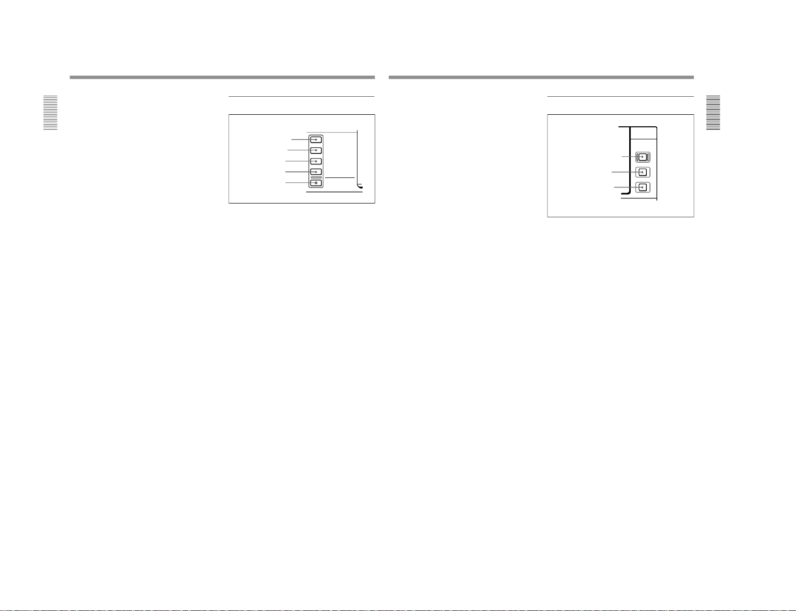
3 Remote control setting section
1 REMOTE button
When remote-controlling this unit from the unit
connected to the REMOTE-IN, REMOTE-OUT or
i.LINK connector, press this button, turning it on.
2 9PIN button
When carrying out remote control between this unit
and the unit connected to the REMOTE-IN or
REMOTE-OUT connector, press this button, turning it
on.
3 i.LINK button
When carrying out remote control between this unit
and the unit connected to the i.LINK connector, press
this button, turning it on.
This button is effective only when the optional DSBK190 i.LINK/DV Input/Output Board is installed.
REMOTE
9PIN
i.LINK
2 9PIN button
1 REMOTE button
3 i.LINK button
DSR-2000/2000P
1-1. DSR-2000
DSR-2000/2000P
Location and Function of Parts
Chapter 1 Overview
16
Chapter 1 Overview
Lower Control Panel
FULL/FINE
PHONE LEVEL
CH-1
REC
PB
ASSEMBLE
HEADPHONES
PREVIEW REVIEW
AUTO
DMC EDIT
DELETE
MEMORY
VIDEO
INSERT
CH-1 CH-2 CH-3 CH-4 TC
CH-2 CH-3 CH-4
CH-4CH-3CH-2CH-1
L
R
TRIM
PULL FOR VARIABLE
IN
OUT
IN OUT
AUDIO
REC
STANDBY
EJECT REW PLAY F FWD STOP
SEARCH VARIABLE
PREROLL
EDIT
PLAYERRECORDER
ENTRY SHIFT
LIST MARK
PREREAD PB/EE PB MENU SET HOLD
COUNTER SEL
RESET
CHANNEL
CONDITION
-+
MONITOR SELECT
METER
EDIT
ClipLink
LP
VITC
INHIBIT
KEY INHIBIT SERVO
SHUTTLE
JOG
COUNTER
HOURS MINUTES SECONDS FRAMES
REPEAT
NOT
EDITABLE
REC
U-BIT TC
1 METER FULL/FINE button
2 REC controls
3 PB controls
4 MONITOR SELECT buttons
5 HEADPHONES jack and PHONE LEVEL control
1 Monitor/menu/display setting
section
(see page 17)
2 Display section
(see page 18)
3 Edit mode setting section
(see page 20)
4 Editing control section
(see page 21)
5 Tape transport control
section
(see page 22)
6 Search control section
(see page 23)
1 METER FULL/FINE button
This switches the display mode of the audio level
meters in the upper control panel as follows:
FULL: In this mode the segment of the display
corresponding to the current audio level and all
lower segments light. A marker indicating the
reference level (set with extended menu item 811)
also appears.
FINE: The display is enlarged, with a step of 0.25 dB
with respect to the reference level of 0 dB.
In this mode only the segment of the display
corresponding to the current audio level lights. If
the audio level exceeds the maximum display
level, the top segment flashes, and if the audio
level goes below the minimum display level, the
bottom segment flashes.
2 REC (recording) controls
These individually adjust the recording levels on
channels 1 to 4.
To set the recording level, put the unit in E-E mode,
pull out the control knobs and adjust the level while
watching the level meters.
When the control knobs are pushed in, the recording
levels return to the preset levels and cannot be
adjusted.
For details of selecting the E-E mode, see the description of
the REC button in the tape transport control section (see
page 22) and the PB/EE button in the monitor/menu/display
setting section (see page 17).
6 PLAYER button and RECORDER button
Chapter 1 Overview
Chapter 1 Overview
17
3 PB (playback) controls
These adjust individually the playback levels on
channels 1 to 4.
During playback, pull out the control knobs and adjust
the level while watching the level meters.
When the control knobs are pushed in, the playback
levels return to the preset levels, and cannot be
adjusted.
4 MONITOR SELECT buttons
There are four buttons CH-1 to CH-4 (channels 1 to 4)
in each of the upper (L) and lower (R) rows. Use these
buttons to select the channels for audio output via the
HEADPHONES connector on the lower control panel
and the MONITOR AUDIO connector on the
connector panel.
The HEADPHONES connector outputs stereo sound
(L and R) and the MONITOR AUDIO connector
outputs monaural sound (L and R mixed).
You can select two or more channels in either row by
pressing the buttons for the desired channels
simultaneously. The sounds of the channels selected in
the row are mixed.
In 2-channel audio recording mode (selected with
extended menu item 818), it is possible to use the
AUDIO OUT CH-3 and AUDIO OUT CH-4
connectors for monitor audio output for channels 1 and
2, respectively (use extended menu item 820).
5 HEADPHONES jack and PHONE LEVEL
control
Connect stereo headphones with an impedance of 8
ohms to monitor the sound during recording, playback
and editing.
The PHONE LEVEL control knob adjusts the volume.
6 PLAYER button and RECORDER button
When you carry out editing using a VCR connected to
the REMOTE-IN or REMOTE-OUT connector as the
player and this unit as the recorder, these buttons select
which VCR the editing control buttons and tape
transport buttons on this unit control.
PLAYER: The editing control buttons and tape
transport buttons on this unit control the external
player VCR.
RECORDER: The editing control buttons and tape
transport buttons on this unit control the recorder
(this unit).
When this unit is being used in standalone mode,
neither button functions.
1 Monitor/menu/display setting section
PREREAD PB/EE PB MENU SET HOLD
COUNTER SEL
RESET
1 PREREAD button
2 MENU button
3 SET button
4 RESET button
5 PB/EE button
6 PB button
7 HOLD button
8 COUNTER SEL button
1 PREREAD button
When this is lit, a preread (read-before-write) is carried
out in insert editing.
For details of preread editing, see the section
“Preread
Editing” (page 87).
2 MENU button
Use this button for setup menu operations.
Pressing this button, turning it on, shows setup menus
in the time counter display (see page 18).
Press the button once more to exit from the menu
display.
For details of setup menu operations, see Chapter 6
“Setup
Menu” (page 107).
3 SET button
Use this button for setting time code and user bit
values and in setup menu operations.
For details of setting time code and user bit values see
Chapter 2 “Setting/Displaying Time Data and Text
Information” (page 35).
1-9
1-1. DSR-2000
1-10
Location and Function of Parts
Chapter 1 Overview
18
Chapter 1 Overview
4 RESET button
To reset a time counter value (COUNTER) shown in
the time counter display, press this button.
Resetting the COUNTER value erases all edit points.
This button is also used for setting time code and user
bit values and in setup menu operations.
5 PB/EE (playback/E-E) button
To select E-E mode input signals for the video/audio
signals output during fast forward, rewind, still, and
standby, press this button, turning it on.
Either one of this button and the PB button is always
lit.
6 PB (playback) button
To select playback signals for the video/audio signals
output during fast forward, rewind, still, and standby,
press this button, turning it on.
Either one of this button and the PB/EE button is
always lit.
7 HOLD button
To stop updating of the time code or user bit value in
the time counter display (that is, to hold the display),
press this button, turning it on. To set a time code or
user bit value, first press this button to hold the value.
8 COUNTER SEL (select) button
This switches the value shown in the time counter
display in the following sequence: COUNTER, TC, UBIT.
Time counter display selection
a) The selection of TC or VITC is made by the TC SELECT
switch on the subsidiary control panel.
Selection Value displayed
COUNTER Tape running time (hours, minutes,
seconds, frames)
TC
Playback time code read by the internal
time code reader or time code being
recorded.
a)
U-BIT User bit value inserted in the playback time
code or time code being recorded.
a)
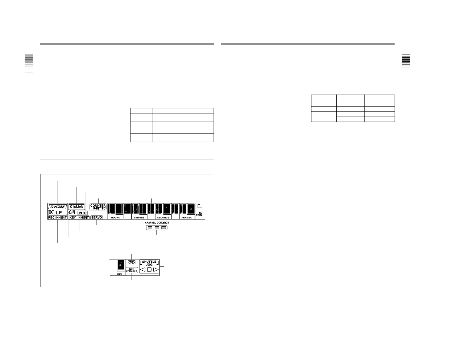
2 Display section
1 Recording/playback format indicators
2 ClipLink indicator
3 VITC indicator
4 Time data type indicators
5 Time counter display
6 REC INHIBIT indicator
7 Cassette memory indicator
8 KEY INHIBIT indicator
9 SERVO indicator
!º CHANNEL CONDITION indicator
!¡Tape end alarm indicator
!™ SHUTTLE/JOG indicators
!£ NOT EDITABLE indicator
Chapter 1 Overview
Chapter 1 Overview
19
1 Recording/playback format indicators
DVCAM: This lights when a tape recorded in
DVCAM format is played back.
DV: This lights when a tape recorded in consumer
DV format is played back.
LP: This lights when a tape recorded in LP mode is
played back.
When a tape recorded in DVCPRO (25) format or any
other format than those mentioned above is played
back, none of the above indicators lights.
2 ClipLink indicator
Lights when a cassette is loaded on which ClipLink
log data is stored in the cassette memory.
For details of ClipLink log data, see the appendix
“ClipLink
Guide” (page 147).
3 VITC indicator
Regardless of the data shown in the time counter
display, this indicator lights when VITC in the signal
played back or in the input video signal (in E-E mode)
is being read.
4 Time data type indicators
One of the three indicators (COUNTER, U-BIT, and
TC) lights to indicate the type of time data currently
shown in the time counter display.
COUNTER: Count value of the time counter
U-BIT: User bit data
TC: SMPTE time code (DSR-2000) or EBU time
code (DSR-2000P)
5 Time counter display
Indicates the count value of the time counter, time
code, or user bit data depending on the settings of the
COUNTER SEL button in the monitor/menu/display
setting section and the TC SELECT switch on the
subsidiary control panel.
Also used to display edit point values, edit duration
values, error messages and setup menu data.
6 REC (recording) INHIBIT indicator
This indicator is on or off according to the
combination of the setting of the REC INHIBIT switch
on the subsidiary control panel and the REC/SAVE
switch on the loaded cassette, as shown in the
following table. When this indicator is on, recording
on tape is prohibited.
REC INHIBIT indicator indications
a) It is possible to make a setting (extended menu item 107)
so that in this case the indicator flashes.
7 Cassette memory indicator
Lights when a cassette provided with a memory chip
(“cassette memory”) is loaded.
8 KEY INHIBIT indicator
This indicator lights when the KEY INHIBIT switch
on the subsidiary control panel is set to ON.
The buttons/switches to be operable even when this
indicator is on can be determined using extended menu
item 118.
9 SERVO indicator
When the drum servo and capstan servo are locked
1)
,
this indicator lights.
!º CHANNEL CONDITION indicator
This three-color indicator shows the state of the
playback signal.
Green: The state of the playback signal is good.
Yellow: The playback signal is somewhat
deteriorated, but playback is possible.
Red: The playback signal is deteriorated.
When the red indicator remains on, head cleaning
or an internal inspection is necessary.
REC INHIBIT
switch position
State of the REC/
SAVE switch on
the cassette
REC INHIBIT
indicator state
ON SAVE/REC Lit
OFF SAVE Lit
a)
REC Off
1) Servo lock: This refers to the synchronization of the
phase of the drum rotation and the reference signal for the
tape transport position, so that the video heads can trace
the same pattern on the tape for playback or recording.
...............................................................................................................................
..........................................................
DSR-2000/2000P
1-1. DSR-2000
DSR-2000/2000P
Location and Function of Parts
Chapter 1 Overview
20
Chapter 1 Overview
ASSEMBLE
VIDEO
INSERT
CH-1 CH-2 CH-3 CH-4 TC
!¡ Tape end alarm indicator
Starts flashing when the remaining capacity of the tape
is for about 2 minutes.
!™ SHUTTLE/JOG indicators
When searching in shuttle or variable mode using the
search dial, the SHUTTLE indicator lights, and when
searching in jog mode using the search dial, the JOG
indicator lights. When the search dial is turned
clockwise causing playback to take place in the
forward direction, the · indicator lights. When the
search dial is turned counterclockwise causing
playback to take place in the reverse direction, the ª
indicator lights. When the tape is stopped, the π
indicator lights.
For more information about the search dial, see page 23.
!£ NOT EDITABLE indicator
Lights during playback of a tape that contains a
recording in other than the DVCAM format. When
this indicator is lit, the recordings contained in the tape
can be used as source material for editing, but editing
operations such as insert editing and assemble editing
cannot be performed.
This indicator also lights when the audio recording
mode selected on this unit does not coincides with that
of the loaded tape.
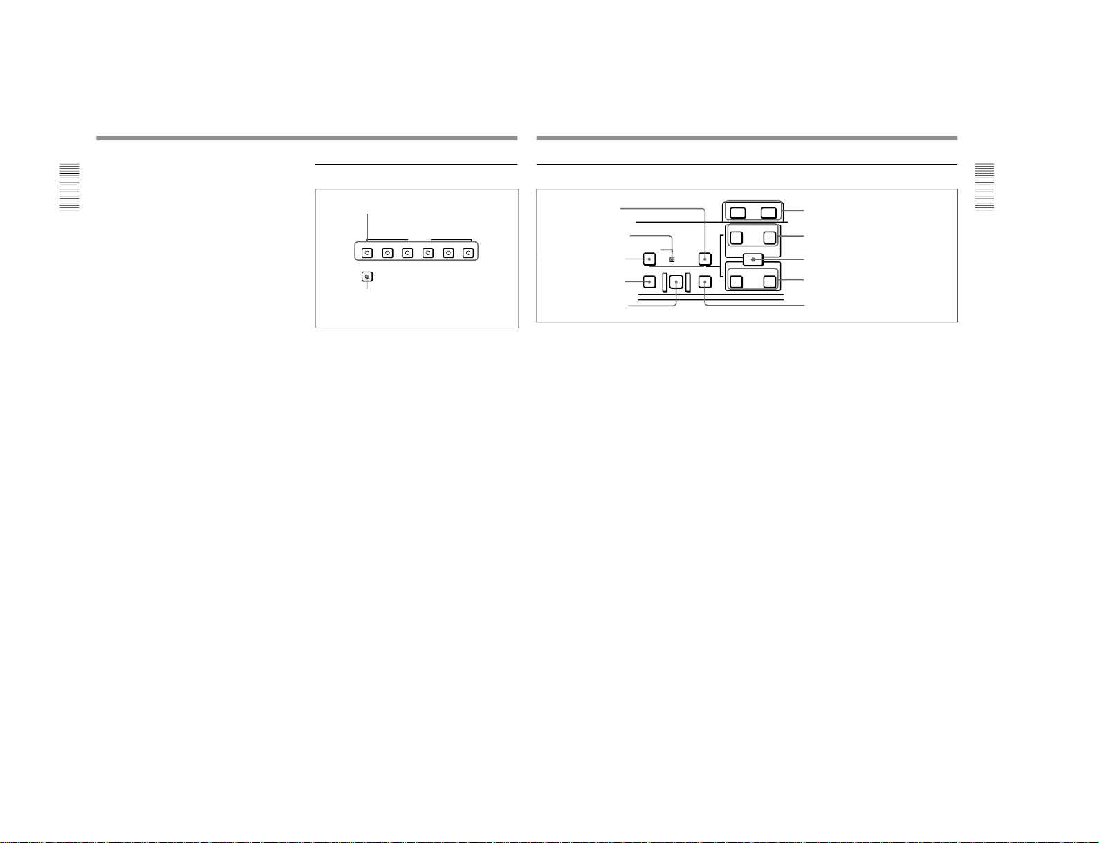
3 Edit mode setting section
1 INSERT buttons
Use these buttons to select the signals for insert
editing
1)
.
VIDEO: To select the video signal, press this button,
turning it on.
CH-1 to CH-4 (channel 1 to channel 4): To select
audio channels 1 to 4, press these buttons, turning
them on. You can select any number of the
channels.
TC: To select time code, press this button, turning it
on.
2 ASSEMBLE button
Press this button, turning it on, to carry out assemble
editing
2)
.
All signals (video signals, audio signals, time code
signals, and so forth) are recorded together.
1 INSERT buttons
2 ASSEMBLE button
1) Insert editing: Editing in which new video/audio is added
into the middle of existing recorded video/audio.
...............................................................................................................................
..........................................................
2) Assemble editing: Editing in which new video/audio is
added in sequence to the end of existing recorded video/
audio.
Chapter 1 Overview
Chapter 1 Overview
21
4 Editing control section
PREVIEW REVIEW
AUTO
DMC EDIT
DELETE
MEMORY
TRIM
IN
OUT
IN OUT
AUDIO
ENTRY SHIFT
LIST MARK
-+
EDIT
6 TRIM buttons
7 AUDIO IN button and AUDIO OUT button
8 ENTRY/SHIFT button
9 IN button and OUT button
!º REVIEW button
2 MEMORY indicator
1 DELETE button
3 DMC EDIT button
4 PREVIEW button
5 AUTO EDIT button
1 DELETE button
This deletes an existing edit point.
Hold down this button and press the IN, OUT, AUDIO
IN, or AUDIO OUT button which is lit, indicating an
existing edit point. The button either goes off or
flashes and the corresponding edit point is deleted.
When the button flashes, it is necessary to set the
deleted edit point again.
2 MEMORY indicator
When memorizing the playback speed using the DMC
EDIT button, this indicator flashes as the playback
speed is captured to memory, and lights continuously
once the speed is captured.
3 DMC EDIT button
Use this button to memorize the playback speed varied
between ±1 times normal speed and carry out
automatic playback or automatic editing using the
memorized playback speed.
For information about how to carry out DMC playback or
DMC editing using this button, see the section
“Dynamic
Motion Control (DMC) Playback
” (page 55) and “DMC
Editing” (page 84), respectively.
4 PREVIEW button
After setting edit points, to preview the editing results
before carrying out the edit, press this button, turning it
on.
If the IN point is not set, the preview is carried out
with the point where you pressed this button as the IN
point.
During the preview the button is lit, and when the
preview ends it flashes.
5 AUTO (automatic) EDIT button
After setting edit points, to carry out automatic editing
(recording), press this button, turning it on.
If the IN point is not set, the automatic editing is
carried out with the point where you pressed this
button as the IN point.
If you pressed the PREVIEW button to carry out a
preview, when the preview ends this button flashes.
6 TRIM buttons
Use these buttons to trim an edit point to single-frame
precision.
Hold down the IN, OUT, AUDIO IN, or AUDIO OUT
button, and press one of these buttons. The MARK/+
button advances the corresponding edit point by one
frame, and the LIST/− button sets it back by one
frame.
During playback, pressing one of these buttons while
holding down the PLAY button adjusts the tape speed
by +8% or −8%, correspondingly. (Capstan override
function)
These buttons are also used for ClipLink operations
and setup menu operations.
For more information about ClipLink operations and setup
menu operations, see Chapter 5
“ClipLink Operation
”
(page 97) and Chapter 6
“Setup Menu” (page 107),
respectively.
7 AUDIO IN button and AUDIO OUT button
In insert editing, to set an audio IN point or audio OUT
point separate from the corresponding video edit point,
hold down the AUDIO IN button or AUDIO OUT
button, and press the ENTRY/SHIFT button.
After you have made the setting, pressing the AUDIO
IN button or AUDIO OUT button displays the audio
IN point or audio OUT point set on the time counter
display.
1-11
1-1. DSR-2000
1-12
Location and Function of Parts
Chapter 1 Overview
22
Chapter 1 Overview
8 ENTRY/SHIFT button
Use this button for setting edit points, carrying out
ClipLink operations, and so forth.
•To set a video IN point or OUT point: Hold down the
IN button or OUT button, and press this button.
•To set an audio IN point or OUT point: Hold down
the AUDIO IN button or AUDIO OUT button, and
press this button.
For more information about ClipLink operation, see
Chapter 5 “ClipLink Operation
” (page 97).
9 IN button and OUT button
To set a video IN point or OUT point, hold down the
IN button or OUT button, and press the ENTRY/
SHIFT button.
After you have made the setting, pressing the IN
button or OUT button displays the IN point or OUT
point on the time counter display.
!º REVIEW button
Use this button to carry out a review of the editing
results after carrying out automatic editing.
5 Tape transport control section
REC
STANDBY
EJECT REW PLAY F FWD STOP
PREROLL
EDIT
1 STANDBY button
2 PREROLL button
3 REC button
4 EDIT button
5 STOP button
6 EJECT button
7 REW button
8 PLAY button
9 F FWD button
1 STANDBY button
When a cassette is inserted and this button is off, to put
the VCR in standby mode, press the button, turning it
on.
In standby mode, the drum is rotating and the tape is in
contact with the drum. As a result, recording or
playback can start immediately.
To end standby mode, press the STANDBY button,
turning it off.
If a certain period of time (value can be varied using
extended menu item 501) elapse in standby mode, the
unit automatically switches out of standby mode to
protect the tape.
2 PREROLL button
Press this button to cue up to the preroll point (before
the IN point by the time set as the preroll time) on the
tape. You can change or select the preroll time and the
state of the unit at the end of preroll (stop mode
1)
or
still playback mode) using basic menu item 001 and
extended menu item 401.
Cuing up to edit points
Hold down the IN, OUT, AUDIO IN, or AUDIO OUT
button while pressing this button to cue up to the
corresponding edit point.
3 REC (record) button
To start recording, press this button together with the
PLAY button, turning it on.
Monitoring in E-E mode
When the unit is in stop mode, pressing this button
lights it, and you can monitor the video and audio in EE mode. To return to the original state, press the STOP
button.
During playback, search, fast forward, or rewind,
holding down this button allows you to monitor the
video and audio in E-E mode. In this case the button
does not light.
1) Stop mode: the state in which the device currently the
subject of operation is stopped, and the STOP button is
lit.
...............................................................................................................................
..........................................................
Chapter 1 Overview
Chapter 1 Overview
23
4 EDIT button
To carry out manual editing, press this button
simultaneously with the PLAY button.
Monitoring in E-E mode
When the unit is in stop mode, pressing this button
lights it, and you can monitor the input signal selected
with the ASSEMBLE button or INSERT buttons in EE mode. To return to the original state, press the STOP
button. During playback, search, fast forward, or
rewind, holding down this button allows you to
monitor the video in E-E mode.
5 STOP button
To stop recording or playback, press this button,
turning it on.
When you stop playback, the unit switches either to
still playback or to E-E mode according to setup menu
settings, and the settings of the PB/EE button and PB
button.
Fault display function
This button flashes when there is no external reference
signal input or the input external reference signal is not
synchronized to the input video signal. (See the
description of extended menu item 105.)
6 EJECT button
To eject the cassette, press this button. While the
cassette is being ejected, this button lights.
7 REW (rewind) button
To rewind the tape, press this button, turning it on.
8 PLAY button
To start playback, press this button, turning it on.
To operate in capstan override mode
Hold down this button, and turn the search dial.
For details of capstan override mode, see
“
3 Search dial”
on this page.
9 F FWD (fast forward) button
To fast forward the tape, press this button, turning it
on.
6 Search control section
1 SEARCH button
To use the search dial for playback in shuttle or jog
mode, press this button, turning it on. Pressing the dial
toggles between shuttle and jog modes. In shuttle
mode, the SHUTTLE indicator in the display section
lights, and in jog mode, the JOG indicator in the
display section lights.
2 VARIABLE button
To use the search dial for playback in variable speed
mode, press this button, turning it on. Pressing the dial
toggles between variable speed mode and jog mode.
3 Search dial
Turn this to carry out playback in the modes shown in
the following table. Turning the dial clockwise lights
the · indicator in the display section and plays back
in the forward direction. Turning the dial
counterclockwise lights the ª indicator in the display
section and plays back in the reverse direction. When
the tape is stopped, the π indicator in the display
section lights.
Pressing this dial toggles between shuttle mode and
jog mode (or between variable mode and jog mode).
When playing back in shuttle or variable mode, the
SHUTTLE indicator in the display section lights, and
when playing back in jog mode, the JOG indicator
lights.
You can carry out noiseless playback in the range of ±
1 times normal speed.
SEARCH VARIABLE
1 SEARCH button
2 VARIABLE button
3 Search dial
DSR-2000/2000P
1-1. DSR-2000

DSR-2000/2000P
Location and Function of Parts
Chapter 1 Overview
24
Chapter 1 Overview
Playback modes using the search dial
Changing the setting of extended menu item 101 enables you
to select shuttle or jog mode just by turning the search dial
without using the SEARCH or VARIABLE button.
Playback
mode
Operations and functions
Shuttle Press the SHUTTLE button or the search dial
so that the SHUTTLE indicator in the display
section lights, then turn the search dial.
Playback is carried out at a speed determined
by the position of the search dial. The
maximum shuttle mode playback speed can be
changed using extended menu item 102.
Jog
Press the SHUTTLE button or the search dial
so that the JOG indicator in the display section
lights, then turn the search dial. Playback is
carried out at a speed determined by the speed
of rotation of the search dial. The playback
speed range is ±1 times normal speed. The
search dial has no detents.
Variable
speed
Press the VARIABLE button, turning it on, then
turn the search dial. You can control the
playback speed finely (61 steps) in the range of
–1 to +2 times normal speed.
The search dial has detents at the still position
and at the normal speed position.
The variable mode playback speed range can
be changed using extended menu item 119.
Noiseless playback is possible in the range of
±1 times normal speed.
Capstan
override
Hold down the PLAY button and turn the
search dial to adjust the playback speed in the
range of ±15%. Use this for phase adjustment
between this unit and an external device
connected to this unit.
Chapter 1 Overview
Chapter 1 Overview
25
Subsidiary Control Panel
OFF ON
CHARACTER
EXT INT
CONTROL PANEL
TC GENERATOR
NDF DF
ON OFF
REC INHIBIT
VITC
OFF ON
ON OFF
KEY INHIBIT
PROCESS
CONTROL
VIDEO
TC SELECT
MENU
PRESET
MANUAL
VITC TC
REC FREE
EXT INT
REMOTE LOCAL
RUN RUN
REGEN PRESET
CHROMA
PRESET
MANUAL
SET UP
PRESET
MANUAL
VIDEO
PRESET
MANUAL
CHROMA
PRESET
MANUAL
SET UP
PRESET
MANUAL
Y/C DELAY
PRESET
MANUAL
CHROMA PHASE
(HUE)
PRESET
MANUAL
SYNC
SYSTEM PHASE
SC
1 CHARACTER switch
2 CONTROL PANEL switch
3 REC INHIBIT switch
4 KEY INHIBIT switch
5 PROCESS CONTROL switch
6 INT/EXT−PRESET/REGEN switch
7 FREE RUN/REC RUN switch
8 DF/NDF switch (DSR-2000 only)
9 VITC switch
!º TC SELECT switch !¡ VIDEO knob and PRESET/MANUAL switch
!£ CHROMA knob and PRESET/MANUAL switch
!™ SET UP (DSR-2000)/BLACK LEVEL (DSR-2000P)
knob and PRESET/MANUAL switch
!¢ Y/C DELAY knob and PRESET/MANUAL switch
!∞ CHROMA PHASE (HUE) (DSR-2000)/
CHROMA PHASE (DSR-2000P) knob and
PRESET/MANUAL switch
!§ SYNC knob
!¶ SC knob
1 CHARACTER switch
Select whether or not to superimpose text information
such as time code, menu settings, and alarm messages
on the video signal output from the SDI OUTPUT 3
(SUPER) connector and VIDEO OUT 3 (SUPER)
connector.
ON: Superimposed text
OFF: No superimposed text
The factory default setting is ON.
2 CONTROL PANEL switch
Select the state of the control panel when this unit is
operated.
INT: When operating this unit by its own control
panel.
EXT: When operating this unit remotely by the
optional DSBK-200 Control Panel connected to
the CONTROL PANEL connector.
The factory default setting is INT.
1-13
1-1. DSR-2000

1-14
Location and Function of Parts
Chapter 1 Overview
26
Chapter 1 Overview
3 REC (record) INHIBIT switch
When this switch is set to ON, the REC INHIBIT
indicator in the display section lights, and recording on
tape is no longer possible. (See the description of
extended menu item 107.)
4 KEY INHIBIT switch
When this switch is set to ON, the KEY INHIBIT
indicator in the display section lights, and the buttons
in the upper control panel and lower control panel
specified by the setting of extended menu item 118 are
disabled.
5 PROCESS CONTROL switch
This selects the method of control of the internal
digital video processor.
REMOTE: Select this position to use an optional
UVR-60/60P or BVR-50/50P Remote Control
Unit for remote control of the internal digital
video processor.
MENU: Select this position to use the setup menu to
change the settings for the internal digital video
processor.
LOCAL: Select this position to use the subsidiary
control panel to change the settings for the internal
digital video processor.
6 INT/EXT–PRESET/REGEN (internal/external−
preset/regenerated) switch
This switch is used to make selections relating to the
time code and the internal time code generator.
(In this Operating Instructions, this switch may also be
called simply as the INT/EXT switch or PRESET/
REGEN switch depending on the contents of the
description in which the switch is referred to.)
Selection of internal/external time code
Selection relating to the internal time code generator
7 FREE RUN/REC RUN switch
This switch selects the time code run mode of the
internal time code generator.
FREE RUN: Regardless of the operating mode of
this unit, the time code value advances
continuously while the power is on.
REC RUN: The time code value advances only
during recording. When this mode is selected, set
the INT/EXT−PRESET/REGEN switch to INT−
PRESET.
8 DF/NDF (drop-frame/non-drop-frame) switch
(for the DSR-2000 only)
This switch selects the mode of advancing the time
code generator and time counter.
DF: Drop-frame mode
NDF: Non-drop-frame mode
Note
When the PRESET/REGEN switch is set to REGEN,
since the time code generator is synchronized to the
playback time code, this switch has no effect.
9 VITC switch
To record the time code produced by the internal time
code generator as a VITC, set this switch to ON.
When this switch is set to OFF, internally generated
time code is not recorded as VITC, but VITC present
in the input video signal is recorded unchanged.
!º TC (time code) SELECT switch
This switch selects the time code, TC or VITC, shown
in the time counter display.
Setting
Operation of the internal time code generator
PRESET The initial value of the time code produced by
the internal time code generator can be preset
by a control panel operation or by remote control
from a device connected to the REMOTE-IN or
REMOTE-OUT connector.
REGEN The internal time code reader is synchronized to
the playback time code read by the internal time
code reader.
Setting
Time code used
INT
The time code produced by the internal time
code generator
By setting the switch to INT
–REGEN or INT–
PRESET, you can select
“PRESET” or “REGEN”
for the internal time code generator
(see the
next table)
.
EXT The external time code selected as follows.
• When the TC SELECT switch is set to TC
The external time code input to the TIME
CODE IN connector
• When the TC SELECT switch is set to VITC
The VITC time code included in the input
video signal
In this case, for the internal time code generator,
“REGEN” is always selected
(see the next
table)
.
Chapter 1 Overview
Chapter 1 Overview
27
!¡ VIDEO knob and PRESET/MANUAL switch
The switch makes the selection described below.
When it is set to MANUAL, you can use the knob to
adjust the video signal output level.
PRESET: Regardless of the position of the knob, the
video signal output level is set to the reference
value.
MANUAL: You can adjust the video signal output
level in the range ±3 dB.
You can change the adjustment range using
extended menu item 714.
!™ SET UP (DSR-2000)/BLACK LEVEL (DSR2000P) knob and PRESET/MANUAL switch
The switch makes the selection described below.
When it is set to MANUAL, you can use the knob to
adjust the (black) setup level (DSR-2000) or black
level (DSR-2000P).
PRESET: Regardless of the position of the knob, the
setup level (DSR-2000) or black level (DSR2000P) is set to the reference value.
MANUAL: You can adjust the setup level (DSR-
2000) in the range ±30 IRE
1)
, or the black level
(DSR-2000P) in the range ±210 mV.
!£ CHROMA (chrominance) knob and PRESET/
MANUAL switch
The switch makes the selection described below.
When it is set to MANUAL, you can use the knob to
adjust the chrominance signal output level.
PRESET: Regardless of the position of the knob, the
chrominance signal output level is set to the
reference value.
MANUAL: You can adjust the chrominance signal
output level in the range ±3 dB.
You can change the adjustment range using
extended menu item 714.
1) IRE: A unit for representing a video level laid down by
the IRE (Institute of Radio Engineers). The IRE is now
the IEEE (Institute of Electrical and Electronic
Engineers).
...............................................................................................................................
..........................................................
!¢ Y/C DELAY knob and PRESET/MANUAL
switch
The switch makes the selection described below.
When it is set to MANUAL, you can use the knob to
adjust the Y/C delay.
PRESET: Regardless of the position of the knob, the
Y/C delay is set to the reference value.
MANUAL: You can adjust the Y/C delay in the
range ±100 ns.
!∞ CHROMA PHASE (HUE) (DSR-2000)/
CHROMA PHASE (DSR-2000P) knob and
PRESET/MANUAL switch
The switch makes the selection described below.
When it is set to MANUAL, you can use the knob to
adjust the hue/chrominance phase (the phase
difference from a burst signal).
PRESET: Regardless of the position of the knob, the
hue/chrominance phase is set to the reference
value.
MANUAL: You can adjust the hue/chrominance
phase in the range ±30°.
!§ SYNC knob
This adjusts the output signal sync phase with respect
to the input reference signal to this unit in the range ±3
µs.
Use this adjustment when the output phase of this unit
is not accurately aligned with the reference signal
phase, or when carrying out special effects editing with
this unit and other VCRs connected to a switcher or
other equipment.
!¶ SC (subcarrier) knob
This adjusts the output signal subcarrier phase with
respect to the input reference signal to this unit in the
range ±180°.
For editing with composite signals, use this adjustment
when the output phase of this unit with respect to the
phase of the reference signal is not accurately aligned
with the subcarrier phase.
1-1. DSR-2000
DSR-2000/2000P

DSR-2000/2000P
Location and Function of Parts
Chapter 1 Overview
28
Chapter 1 Overview
Connector Panel
REF.VIDEO
ANALOG VIDEO I/O DIGITAL AUDIO I/O(AES/EBU) SDTI(QSDI)
SDI INPUT SDI OUTPUT
i.LINK
S VIDEO
TIME CODE
MONITOR AUDIO
AUDIO IN
LEVEL
AUDIO OUT
OUT
OUT
OUT
OUT
OUT
(SUPER)
(SUPER)
IN
IN
IN
INPUT OUTPUT
IN
1
123
2
3
IN
REMOTE-OUT
REMOTE-IN
VIDEO CONTROL
~AC IN
CONTROL PANEL
CH-1
CH-2
CH-3
CH-4
CH-1
0dBm
HIGHLOW
OFF
-6dBm +4dBm
CH-2 CH-3
CH-4
OFF
ON
75Ω
VIDEO IN
VIDEO OUT
COMPONENT VIDEO
CH-1/2
CH-1/2
CH-3/4
CH-3/4
OFF
ON
75Ω
Y
R-Y
B-Y
0dBm
-6dBm +4dBm
0dBm
-6dBm +4dBm
0dBm
-6dBm +4dBm
ON
-600
Ω
LEVEL
HIGHLOW
OFF
ON
-600
Ω
LEVEL
HIGHLOW
OFF
ON
-600
Ω
LEVEL
HIGHLOW
OFF
ON
-600
Ω
1 AC IN
connector
2 Ground terminal
1 Analog video input/output section
(see page 29)
2 Digital input/output section
(see page 30)
3 External device connectors
(see page 31)
4 Analog audio input/output section
(see page 31)
This figure shows the connector panel fitted with the optional DSBK-190 i.LINK/DV Input/Output Board.
1 AC IN connector
Use the optional power cord to connect this to an AC
outlet.
2 Ground terminal
Connect this to ground.
Chapter 1 Overview
Chapter 1 Overview
29
1 Analog video input/output section
REF.VIDEO
ANALOG VIDEO I/O
S VIDEO
TIME CODE
OUT
OUT
OUT
OUT
(SUPER)
IN
IN
IN
1
2
3
IN
OFF
ON
75Ω
VIDEO IN
VIDEO OUT
COMPONENT VIDEO
OFF
ON
75Ω
Y
R-Y
B-Y
5 S VIDEO IN connector
1 REF. VIDEO IN connectors
and 75Ω termination switch
2 REF. VIDEO OUT connector
3 TIME CODE IN connector
4 TIME CODE OUT connector
6 S VIDEO OUT connector
7 VIDEO IN connectors and 75Ω termination
switch
8 COMPONENT VIDEO Y/R−Y/B−Y IN
connectors
9 COMPONENT VIDEO Y/R−Y/
B−Y OUT connectors
!º VIDEO OUT 1, 2, and 3 (SUPER) connectors
1 REF. (reference) VIDEO IN connectors (BNC
type) and 75Ω termination switch
Input a reference video signal to one of these
connectors. The two connectors can be used for a loopthrough connection. When making a loop-through
connection, set the termination switch to OFF, and
when not, set the switch to ON.
2 REF. (reference) VIDEO OUT connector (BNC
type)
This connector outputs a reference video signal, except
when i.LINK is selected in the input selection section
(see page 14).
3 TIME CODE IN connector (BNC type)
Input SMPTE time code (DSR-2000) or EBU time
code (DSR-2000P) externally generated to this
connector.
4 TIME CODE OUT connector (BNC type)
This connector outputs a time code according to the
operating state of the unit, as follows:
During playback: the playback time code
During recording: the time code generated by the
internal time code generator or the time code input
to the TIME CODE IN connector.
For more information about the time code output during
recording, see extended setup menu item 611.
5 S VIDEO IN connector (4-pin)
Input an S-video signal with separated Y (luminance)
and C (chroma: 3.58 MHz for DSR-2000 or 4.43 MHz
for DSR-2000P) components to this connector.
6 S VIDEO OUT connector (4-pin)
This connector outputs an S-video signal with
separated Y (luminance) and C (chroma: 3.58 MHz for
DSR-2000 or 4.43 MHz for DSR-2000P) components.
7 VIDEO IN connectors (BNC type) and 75Ω
termination switch
Input an analog composite video signal to one of these
connectors. The two connectors can be used for a loopthrough connection. When making a loop-through
connection, set the 75Ω termination switch to OFF and
when not, set the switch to ON.
1-15
1-1. DSR-2000
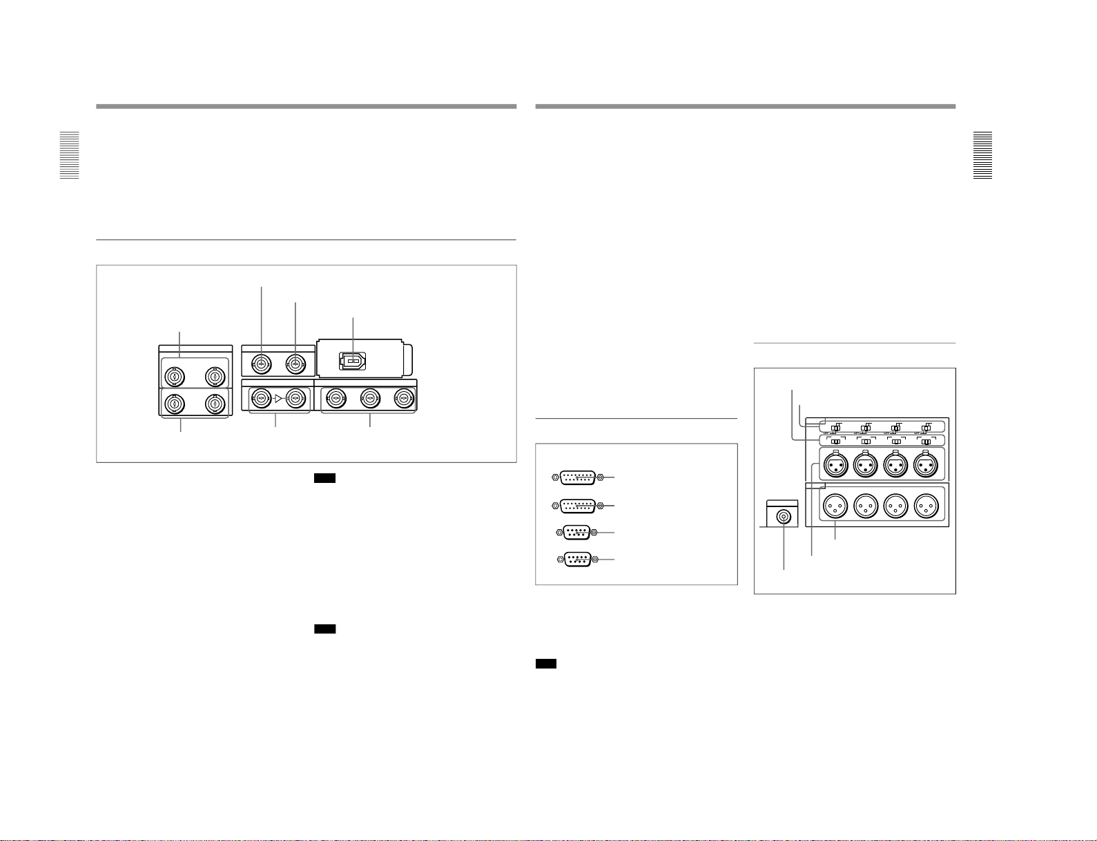
1-16
Location and Function of Parts
Chapter 1 Overview
30
Chapter 1 Overview
8 COMPONENT VIDEO Y/R
–Y/B–Y IN
connectors (BNC type)
Input analog component video signals (Y/R−Y/B−Y)
to these connectors.
9 COMPONENT VIDEO Y/R
–Y/B–Y OUT
connectors (BNC type)
These connectors output analog component video
signals (Y/R−Y/B−Y).
!º VIDEO OUT 1, 2, and 3 (SUPER) connectors
(BNC type)
These connectors output analog composite video
signals.
When the CHARACTER switch on the subsidiary
control panel is set to ON, connector 3 (SUPER)
outputs a signal with superimposed text information.
2 Digital input/output section
DIGITAL AUDIO I/O(AES/EBU) SDTI(QSDI)
SDI INPUT SDI OUTPUT
i.LINK
OUT
(SUPER)
IN
INPUT OUTPUT
123
CH-1/2
CH-1/2
CH-3/4
CH-3/4
1 DIGITAL AUDIO (AES/EBU) IN connectors
2 SDTI(QSDI) INPUT connector
3 SDTI(QSDI) OUTPUT connector
4 i.LINK connector (optional DSBK-190
i.LINK/DV Input/Output Board)
5 DIGITAL AUDIO
(AES/EBU) OUT connectors
6 SDI INPUT connectors
7 SDI OUTPUT 1, 2, and 3 (SUPER)
connectors
1 DIGITAL AUDIO (AES/EBU) IN connectors
(BNC type)
Input digital audio signals in AES/EBU format to these
connectors.
The left-hand connector (CH-1/2) is for audio channels
1 and 2, and the right-hand connector (CH-3/4) is for
audio channels 3 and 4.
2 SDTI (QSDI) (Serial Data Transport Interface
(QSDI)) INPUT connector (BNC type)
Input digital video and audio signals in SDTI (QSDI)
format to this connector.
3 SDTI (QSDI) (Serial Data Transport Interface
(QSDI)) OUTPUT connector (BNC type)
This connector outputs digital video and audio signals
in SDTI (QSDI) format.
Note
If you monitor the output signal from this connector on
another device in E-E mode while making a search at
speeds in the range +1 to +
1
/
30
or –
1
/
30
to –1 times
normal speed, the signal may sound differently than it
does on this unit.
4 i.LINK connector (6-pin IEEE-1394)(optional
DSBK-190 i.LINK/DV Input/Output Board)
This connector is available when the optional DSBK190 i.LINK/DV Input/Output Board is fitted.
This connector inputs and outputs digital video and
audio signals in DV format.
Note
If you monitor the output signal from this connector on
another device in E-E mode while making a search at
speeds in the range +1 to +
1
/
30
or –
1
/
30
to –1 times
normal speed, the signal may sound differently than it
does on this unit.
Chapter 1 Overview
Chapter 1 Overview
31
5 DIGITAL AUDIO (AES/EBU) OUT connectors
(BNC type)
These connectors output digital audio signals in AES/
EBU format.
The left-hand connector (CH-1/2) is for audio channels
1 and 2, and the right-hand connector (CH-3/4) is for
audio channels 3 and 4.
Digital audio signals are always output from this unit
at a sampling frequency of 48 kHz.
6 SDI (Serial Digital Interface) INPUT connectors
(BNC type)
Input digital video and audio signals in SDI (D1)
format to the left-hand connector. The right-hand
connector is for an active-through connection.
7 SDI (Serial Digital Interface) OUTPUT 1, 2 and
3 (SUPER) connectors (BNC type)
These connectors output digital video and audio
signals in SDI (D1) format.
When the CHARACTER switch on the subsidiary
control panel is set to ON, connector 3 (SUPER)
outputs a signal with superimposed text information.
Digital audio signals are always output from this unit
at a sampling frequency of 48 kHz.
3 External device connectors
1 VIDEO CONTROL connector (D-sub 15-pin)
For remote control of the internal digital video
processor, connect an optional remote control unit
such as the UVR-60/60P or BVR-50/50P to this
connector.
Note
Always power off this unit before connecting the
remote control unit.
1 VIDEO CONTROL connector
REMOTE-OUT
REMOTE-IN
VIDEO CONTROL
CONTROL PANEL
2 CONTROL PANEL connector
3 REMOTE-IN connector
4 REMOTE-OUT connector
2 CONTROL PANEL connector (D-sub 15-pin)
When using the optional DSBK-200 Control Panel to
remotely control this unit, connect the DSBK-200 to
this connector.
3 REMOTE-IN connector (D-sub 9-pin)
When controlling this unit from an editing controller
such as the ES-7, PVE-500, BVE-600/800/910, or
RM-450/450CE, connect the unit to the editing
controller via this connector using the supplied 9-pin
remote control cable.
When controlling another VCR from this unit, connect
the VCR to this connector.
4 REMOTE-OUT connector (D-sub 9-pin)
This connector provides the loop-through output for
remote control signals from the REMOTE-IN
connector.
4 Analog audio input/output section
1 AUDIO IN −6dBm/0dBm/+4dBm switches
Set these switches according to the audio input levels
to the AUDIO IN CH-1 to CH-4 connectors.
MONITOR AUDIO
AUDIO IN
LEVEL
AUDIO OUT
CH-1
CH-2
CH-3
CH-4
CH-1
0dBm
HIGHLOW
OFF
-6dBm +4dBm
CH-2 CH-3
CH-4
0dBm
-6dBm +4dBm
0dBm
-6dBm +4dBm
0dBm
-6dBm +4dBm
ON
-600
Ω
LEVEL
HIGHLOW
OFF
ON
-600
Ω
LEVEL
HIGHLOW
OFF
ON
-600
Ω
LEVEL
HIGHLOW
OFF
ON
-600
Ω
1 AUDIO IN −6dBm/0dBm/+4dBm switches
2 AUDIO IN LEVEL/600Ω switches
3 MONITOR AUDIO connector
4 AUDIO IN CH-1 to CH-4 connectors
5 AUDIO OUT CH-1 to CH-4
connectors
1-1. DSR-2000
DSR-2000/2000P

DSR-2000/2000P
Location and Function of Parts
Chapter 1 Overview
32
Chapter 1 Overview
2 AUDIO IN LEVEL/600Ω switches
Set these switches for each channel as shown in the
following table, according to the audio input levels to
the AUDIO IN CH-1 to CH-4 connectors and the
impedance.
Settings of the AUDIO IN LEVEL/600Ω switches
3 MONITOR AUDIO connector (RCA phono
jack)
This connector outputs audio signals for monitoring.
The audio signals to be output from this connector can
be selected with the MONITOR SELECT buttons on
the lower control panel.
4 AUDIO IN CH-1 (channel 1) to CH-4 connectors
(XLR 3-pin, female)
Use these connectors to connect separate channels of
audio input from a player VCR or other external audio
equipment.
5 AUDIO OUT CH-1 (channel 1) to CH-4
connectors (XLR 3-pin, male)
These connectors output channel-1 to channel-4 audio
signals, respectively.
In 2-channel audio recording mode (selected with
extended menu item 818), it is possible to use the
AUDIO OUT CH-3 and AUDIO OUT CH-4
connectors for monitor audio output for channels 1 and
2, respectively (use extended menu item 820).
Audio input
Switch setting
Level Impedance
−60dBs
(microphone input)
High impedance
(about 20kΩ)
LOW-OFF
(left position)
+4dBs/0dBs/−6dBs
(line audio input)
High impedance
(about 20kΩ)
HIGH-OFF
(middle position)
+4dBm/0dBm/−6dBm
(line audio input)
600Ω HIGH-ON
(right position)
Chapter 1 Overview
Chapter 1 Overview
33
Usable Cassettes
This unit can use the DVCAM cassettes listed below.
The * in each model name is actually
“ME”
(indicating that a cassette memory is contained), or
“N” (indicating that no cassette memory is contained).
The numbers in each model name indicate the
maximum recording/playback time (in minutes) for
each model. For example, the PDV-184ME has a
maximum recording/playback time of 184 minutes.
Cassettes usable for playback only
L- and M-size DVCPRO (25M) cassettes are usable
for playback only.
Notes
•If you insert an incorrect type of cassette, it will be
automatically ejected.
•When operating this unit as a player, you can also use
DV cassettes on the unit. However, it is the best
choice to always use DVCAM cassettes because they
are more reliable than DV cassettes whatever your
purpose may be: playback, editing, or long-period
storage of recordings.
•Cassettes that have been recorded by a DV-format
recorder can be played back on this unit but cannot be
used for recording at editing operation such as the
setting of edit points. When you insert such a
cassette into this unit, the NOT EDITABLE indicator
lights up in the lower control panel display section.
DVCAM cassettes
The following figure illustrates the DVCAM cassette
’s
appearance.
Model name Size
PDV-64*/94*/124*/184*/34* Standard size
PDVM-12*/22*/32*/40* Mini size
Mini size
Cassette memory
This memory is used to store ClipLink log data.
For details of ClipLink log data, see the
appendix “ClipLink Guide”
(page 147)
.
REC/SAVE switch
For details of this switch, see
“Preventing
accidental erasure
”
(page 34)
.
Standard size
Notes on using cassettes
•Before storing the cassette, rewind the tape to the
beginning and be sure to put the cassette in its storage
case, preferably on end instead of flat on its side. The
storage case of a DVCAM cassette is specially
designed to ensure a long-period storage of the tape.
Storing a cassette in any other condition (not
rewound, out of its case, etc.) may cause the video
and audio contents to become damaged over time.
•If the cassette memory connector (contact point)
becomes dirty, connection problems may occur,
causing a loss of functions. Remove any dust or dirt
from this area before using the cassette.
•If the cassette is dropped on the floor or otherwise
receives a hard impact, the tape may become
slackened and may not record and/or play back
correctly.
For information about how to check the tape for slack, see
the next section.
Checking the tape for slack
Using a paper clip or a similar object, turn the reel
gently in the direction shown by the arrow. If the reel
does not move, there is no slack. Insert the cassette
into the cassette compartment, and after about 10
seconds take it out.
Reel
Paper clip, etc.
1-1. DSR-2000
1-17
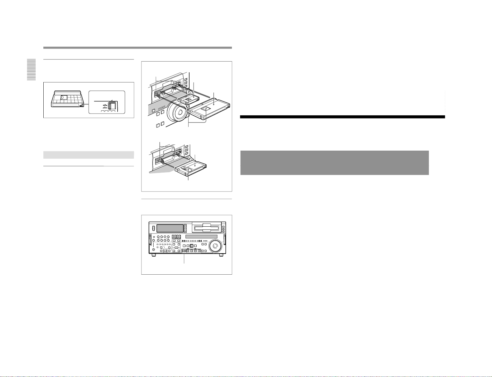
1-18
Location and Function of Parts
Chapter 1 Overview
34
Chapter 1 Overview
Preventing accidental erasure
Set the REC/SAVE switch on the cassette to SAVE to
prevent accidental erasure of recorded contents.
To enable re-recording
Set the cassette’s REC/SAVE switch to REC.
When this switch is set to SAVE, the unit cannot
record on the tape.
Inserting and Ejecting Cassettes
Inserting a cassette
This unit accepts three sizes of cassette: L (standard
size), M (medium size: DVCPRO) and S (mini size).
When inserting a cassette in the unit, make sure its
tape window faces upward as shown in the following
figure.
Set to SAVE
REC/SAVE switch
REC
SAVE
Ejecting a cassette
Press the EJECT button.
Outer guides
Mini size (Insert the cassette
into the middle of the cassette
compartment.)
Standard size
Tape window facing upward
Inner guides
Medium size (Align the
cassette with the outer
guides, then slide it in over
the inner guides.)
EJECT button
Tape window facing upward
Chapter 2 Setting/Displaying Time Data and Text Information
Chapter 2 Setting/Displaying Time Data and Text Information
35
Chapter
2
Setting/Displaying
Time Data and Text
Information
Displaying Time Data and Unit's Operating Status−
Superimposing Text Information
To display superimposed time data and text information about the
operating status of the unit on the monitor, set the CHARACTER switch
on the subsidiary control panel to ON.
When the CHARACTER switch is set to ON, the text information is
superimposed on the output of the VIDEO OUT 3 (SUPER) connector and
also of the SDI OUTPUT 3 (SUPER) connector.
To adjust the displayed text
You can adjust the position, size, and type of superimposed information
using setup menu items 002, 003, 009, and 011.
For details, see pages 108 and 109.
1-1. DSR-2000
DSR-2000/2000P
 Loading...