

Sony DS005AKA Datasheet

Single-Panel Liquid Crystal Optical Engine for Rear Projectors
– 1 –
E99262A97-PS
Sony reserves the right to change products and specifications without prior notice. This information does not convey any license by
any implication or otherwise under any patents or other right. Application circuits shown, if any, are typical examples illustrating the
operation of the devices. Sony cannot assume responsibility for any problems arising out of the use of these circuits.
DS005AKA
Description
The DS005AKA is a single-panel liquid crystal
optical engine for use in rear projectors, and is
capable of full-color displays without color filters (CF).
The DS005AKA employs a square pixel arrangement
optimal for data projector applications, and allows
clear graphic and character displays. Up/down and/or
right/left inversion functions accommodate various
mounting methods.
Short projection distances are made possible through
the adoption of an ultra-wide angle lens. In addition, a
projection lens floating mechanism delivers 40" to 50"
projected images with minimal image distortion.
A high intensity discharge (HID) lamp ensures high
luminance and low power consumption.
Features
• Number of active dots: 1,456,000
• Horizontal resolution: 600 TV lines
• Supports SVGA (804 × 3 × 604)/PC98∗(804 × 3 × 500) mode display
NTSC/NTSC-WIDE/PAL/PAL-WIDE modes also available through conversion of scanned dot numbers by an
external IC
• Up/down and/or right/left inverse display function
• Full-color display with CF-less projection system
• High luminance: normally-white 200 ANSIlm (typ.)
• Ultra-wide angle lens for short projection distances (592.8mm/39.8")
• Image distortion correction floating mechanism to support 40" to 50"
• Relative luminance: 70% or more
• Uses HID lamp (100W)
∗
"PC98" is a trademark of NEC Corporation.
Engine Configuration
• HID lamp
• Lamp driver (DC 300V input)
• High-efficiency illumination system employing an integrator
• Separate RGB illumination systems using dichroic mirrors (DM)
• LCD panel mounting mechanism, adjustable along XYθ axes
• LCD panel (LCX021BM)
Dots: 2412 (H) × 604 (V) = 1,456,848 dots
• Wide fixed focal length lens for enlarged projection of LCD
Applications
Liquid crystal rear projection TV/monitor
For the availability of this product, please contact the sales office.
– 2 –
DS005AKA
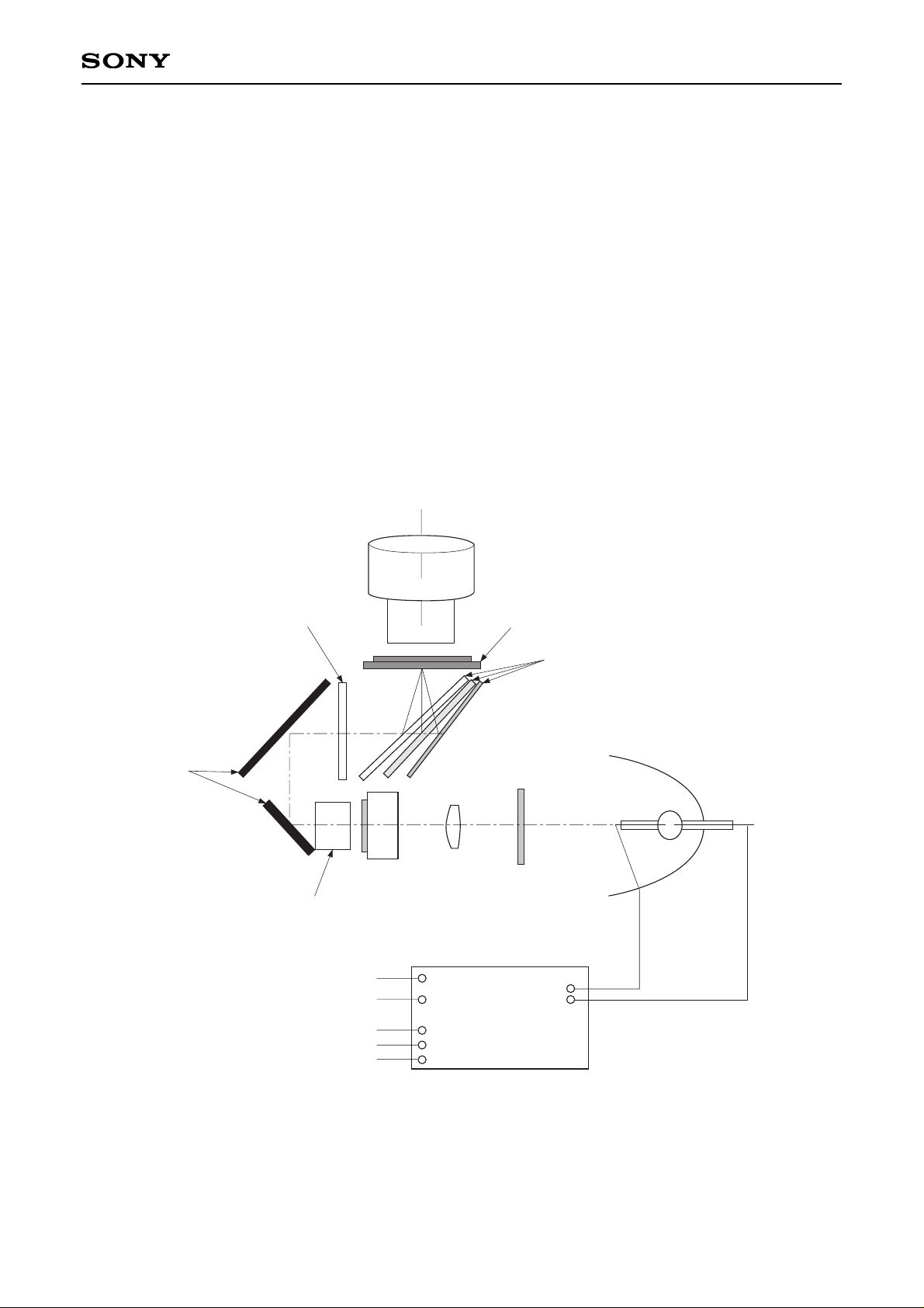
Description of Basic Operation
• Apply DC 300V to the lamp driver.
• Light emitted by the lamp is focused by an elliptical reflector and is converted to an approximately collimated
ray by a relay lens.
• After that the light passes through the polarizer conversion system elements and an optical integrator.
• Light output from the optical integrator passes through a Fresnel lens to become a collimated ray, which is
color-separated by a group of dichroic mirrors.
• The color-separated rays illuminate the LCX021BM evenly, and are focused on the respective RGB dots by
microlenses mounted on the LCX021BM and distributed.
• After transmitting the panel, the light is enlarged and projected onto a screen by a projection lens.
For details of the LCD panel operation, see the LCX021BM specifications.
Block Diagram
Lamp Driver
Positive (DC 300V)
Common
Start control input (SCI)
GND
Signal output
Connector 1
Connector 2
LampUV/IR
Relay Lens
Polarization Conversion
System
Integrator
Fresnel Lens
Mirror
Dichroic Mirrors
LCD with burried Microlens Array
(LCX021BM)
Projection Lens
– 3 –
DS005AKA
Pin Description and Operating Conditions
Absolute Maximum Ratings (∗measured by thermocouples)
Optical engine unit (excluding lamp driver)
• Operating temperature Topr 0 to +40 °C
• Panel and incident side polarizer temperature
∗
55°C or less (∆T = 15°C or less at an ambient temperature of 40°C)
• PBS top (no contact with metal portions)
∗
70°C or less (∆T = 30°C or less at an ambient temperature of 40°C)
• Storage temperature Tstg –20 to +60 °C
Lamp driver unit
• Operating temperature Topr –5 to +65 °C (under forced air cooling)
• Storage temperature Tstg –40 to +85 °C
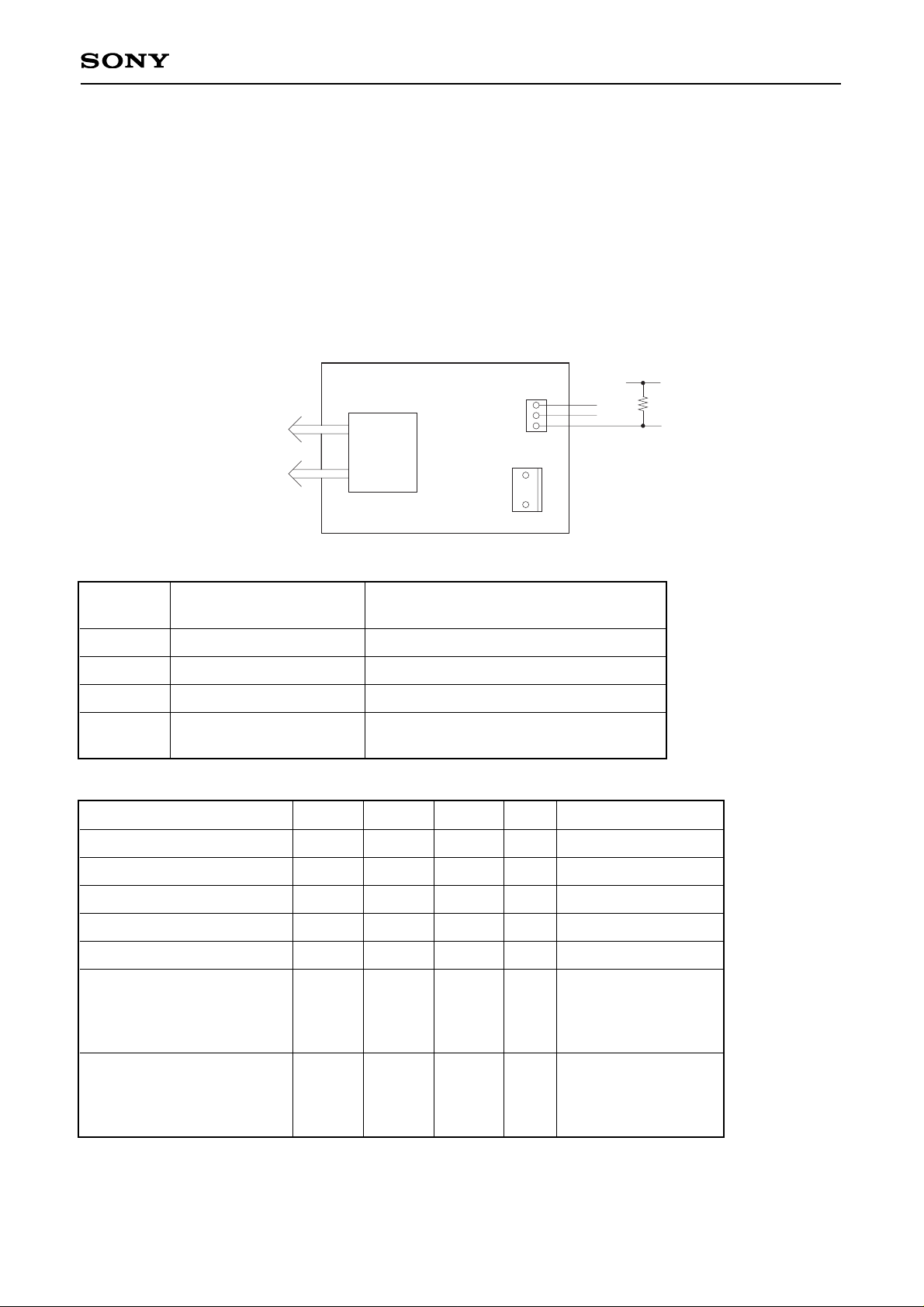
Lamp Driver Unit
+5V
4.7kΩ
Signal output
SCI
GND
1
2
3
Connector 2
Connector 1
1
3
To lamp
(Flag output)
Pin Description
Operating Conditions
Connector 1
DC power supply input
Connector 2
SCI (start control input) and signal output
1
2
3
Connector
type
Positive (DC 300V)
—
Common
JST (J.S.T. Mfg. Co., Ltd.)
B 2P3-VH-B
Start control input (SCI)
GND
Signal output (flag output)
JST (J.S.T. Mfg. Co., Ltd.)
B 3B-PH-K
Input voltage
Power consumption
Circuit loss
Lamp output
Lamp startup peak voltage
Start control input (SCI)
Input voltage
Lamp extinguish
Lamp light
Signal output (flag output)
Output voltage
Lamp extinguish
Lamp light
Min.
220
105
—
95
—
—
3.5
—
3.5
Typ.
300
110
10
100
—
—
5.0
—
—
Max.
390
120
15
105
25
1.0
7.0
1.0
—
Unit
V
W
W
W
kV
V
V
V
V
Remarks
Input current < 1.0mA
Input current < 5.0mA
For details of the LCD panel operating conditions and pin description, see the LCX021BM specifications.
– 4 –
DS005AKA
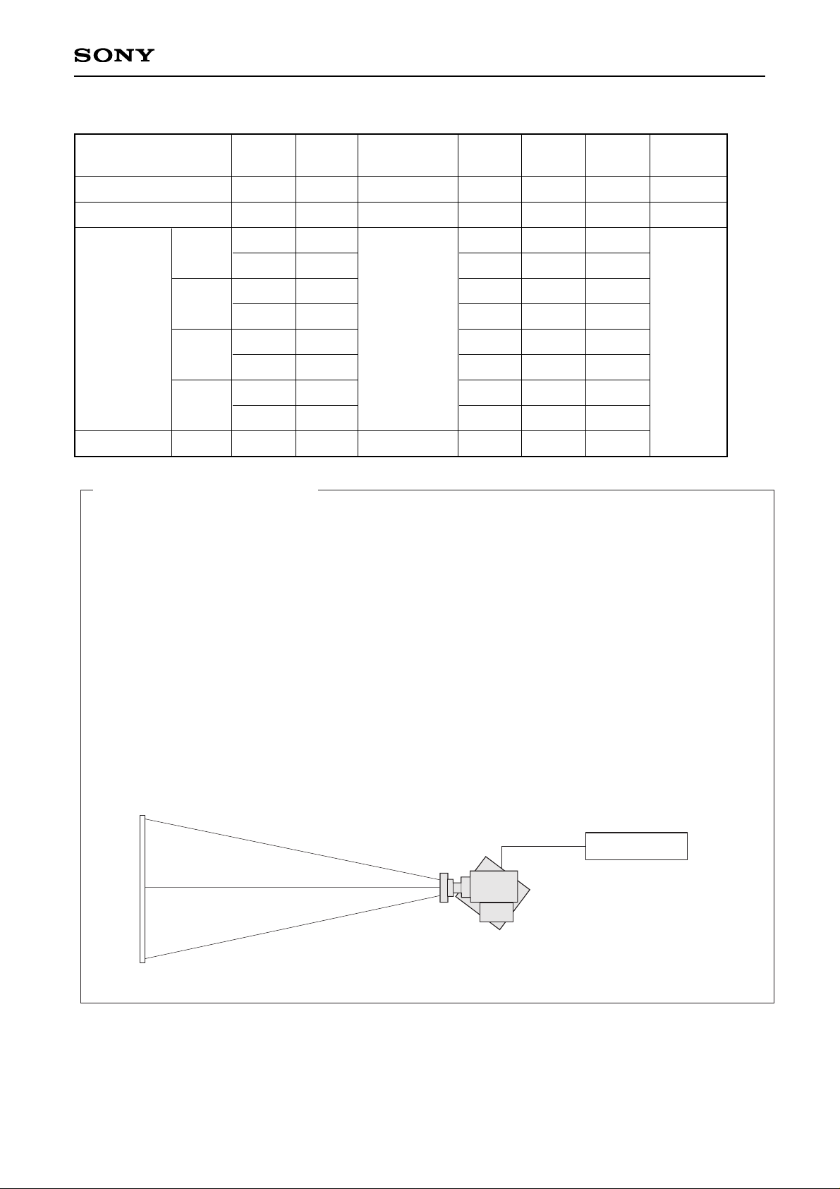
Electro-optical Characteristics (Ta = 25°C)
Basic Measurement Conditions
(1) LCD driving voltage
HVDD = 15.5V, VVDD = 15.5V, VVC = 7.0V, Vcom = 6.6V
(2) Lamp output
100W
(3) Cooling conditions
Forced air cooling by DC fans
(4) Measurement temperature
25°C unless otherwise specified.
(5) Measurement point
One point in the center of the screen unless otherwise specified.
(6) Measurement system
The measurement system is as shown below.
(7) Video input signal voltage Vsig
Vsig = 7.0 ± VAC [V] (VAC = signal amplitude)
LCD driver circuit
Projected size 40"
Measurement System I
25°C
25°C
x
y
x
y
x
y
x
y
∆u'v'
Symbol
CR25
L
Rx
Ry
Gx
Gy
Bx
By
Wx
Wy
∆u'v'w
Measurement
method
1
2
3
4
Min.
130
150
0.570
0.300
0.265
0.620
0.125
0.030
0.240
0.300
—
Typ.
180
200
0.600
0.340
0.305
0.660
0.155
0.060
0.280
0.340
0.015
Max.
—
—
0.640
0.380
0.345
0.700
0.185
0.090
0.320
0.380
0.025
Unit
—
ANSIlm
CIE
standards
Item
R
G
B
W
W
Contrast ratio
Luminous intensity
Chromaticity
Color shading
 Loading...