

Digital Camera
DMC-FX8PL
DMC-FX8EB
DMC-FX8EF
DMC-FX8EG
DMC-FX8EGM
DMC-FX8GC
DMC-FX8GD
ORDER NO. DSC0506012C0
DMC-FX8GK
DMC-FX8GN
DMC-FX8GT
DMC-FX8SG
Vol. 1
Colour
(S)...........Silver Type
(K)...........Black Type (Except PL/GD/GN/SG)
(A)...........Blue Type (Except PL/EB/GD/GN/SG)
(P)...........Pink Type (Except PL/EB/EF/GD/GN/SG)
© 2005 Matsushita Electric Industrial Co., Ltd. All
rights reserved. Unauthorized copying and
distribution is a violation of law.
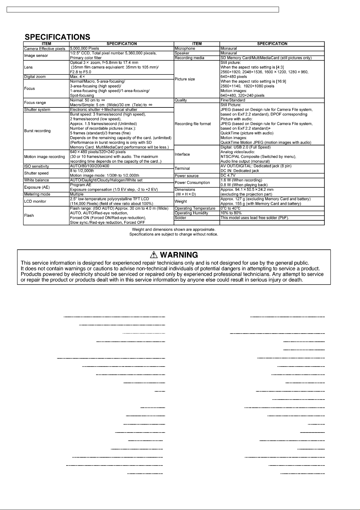
DMC-FX8PL / DMC-FX8EB / DMC-FX8EF / DMC-FX8EG / DMC-FX8EGM / DMC-FX8GC / DMC-FX8GD / DMC-FX8GK / DMC-FX8GN / DMC-FX8GT / DMC-FX8SG
CONTENTS
Page Page
1 INTRODUCTION 4
1.1. INTRODUCTION
1.2. ABOUT LEAD FREE SOLDER (PbF)
1.3. IMPORTANT NOTICE 1:
1.4. HOW TO DEFINE THE MODEL SUFFIX (NTSC or PAL
model)
2 SAFETY PRECAUTIONS
2.1. GENERAL GUIDELINES
2.2. LEAKAGE CURRENT COLD CHECK
2.3. LEAKAGE CURRENT HOT CHECK (See Figure 1.)
3 PREVENTION OF ELECTRO STATIC DISCHARGE (ESD) TO
ELECTROSTATICALLY SENSITIVE (ES) DEVICES
4 CAUTION FOR AC CORD (EB/GC/SG only)
4.1. INFORMATION FOR YOUR SAFETY
4.2. CAUTION FOR AC MAINS LEAD
5 HOW TO REPLACE THE LITHIUM BATTERY
5.1. REPLACEMENT PROCEDURE
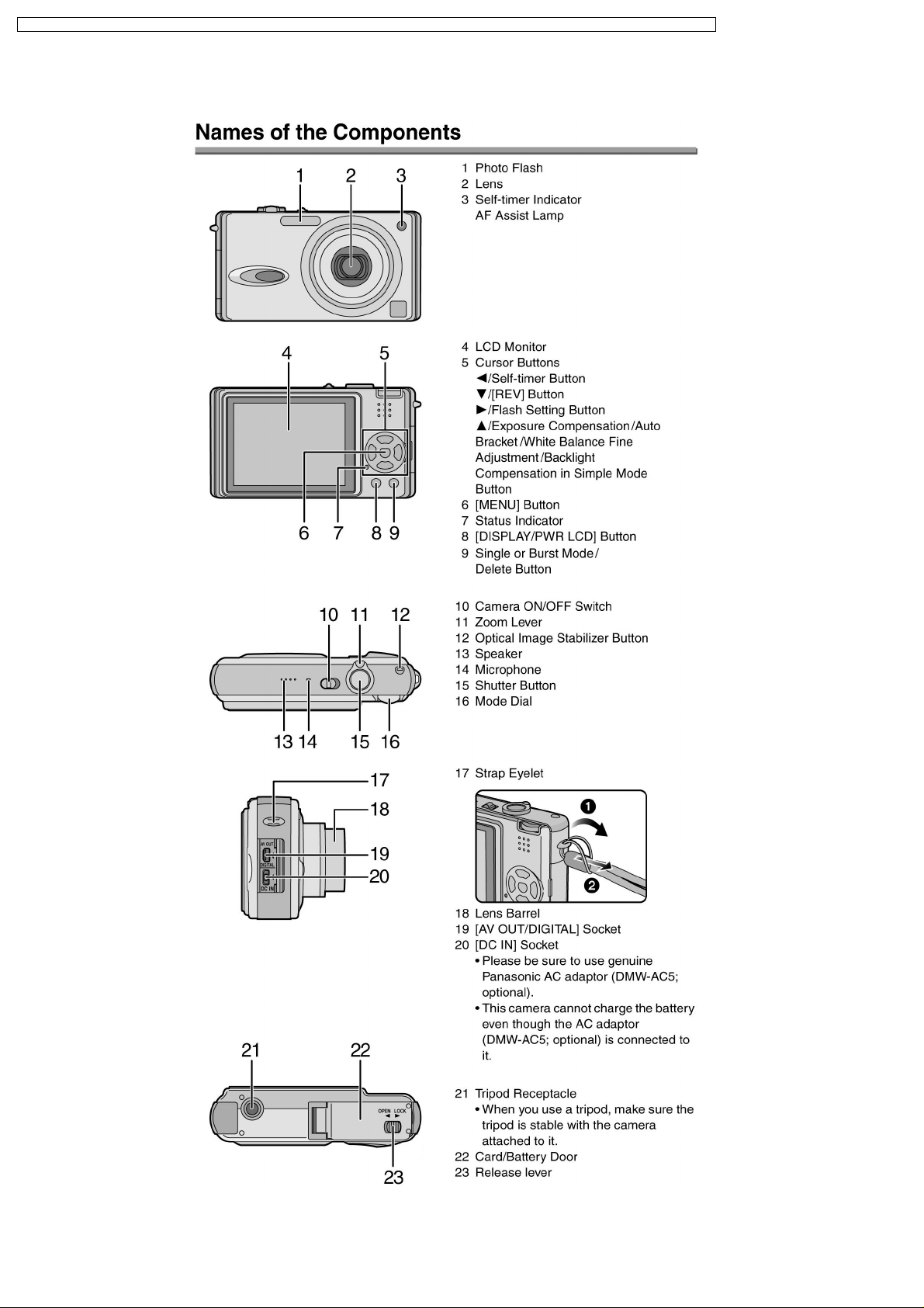
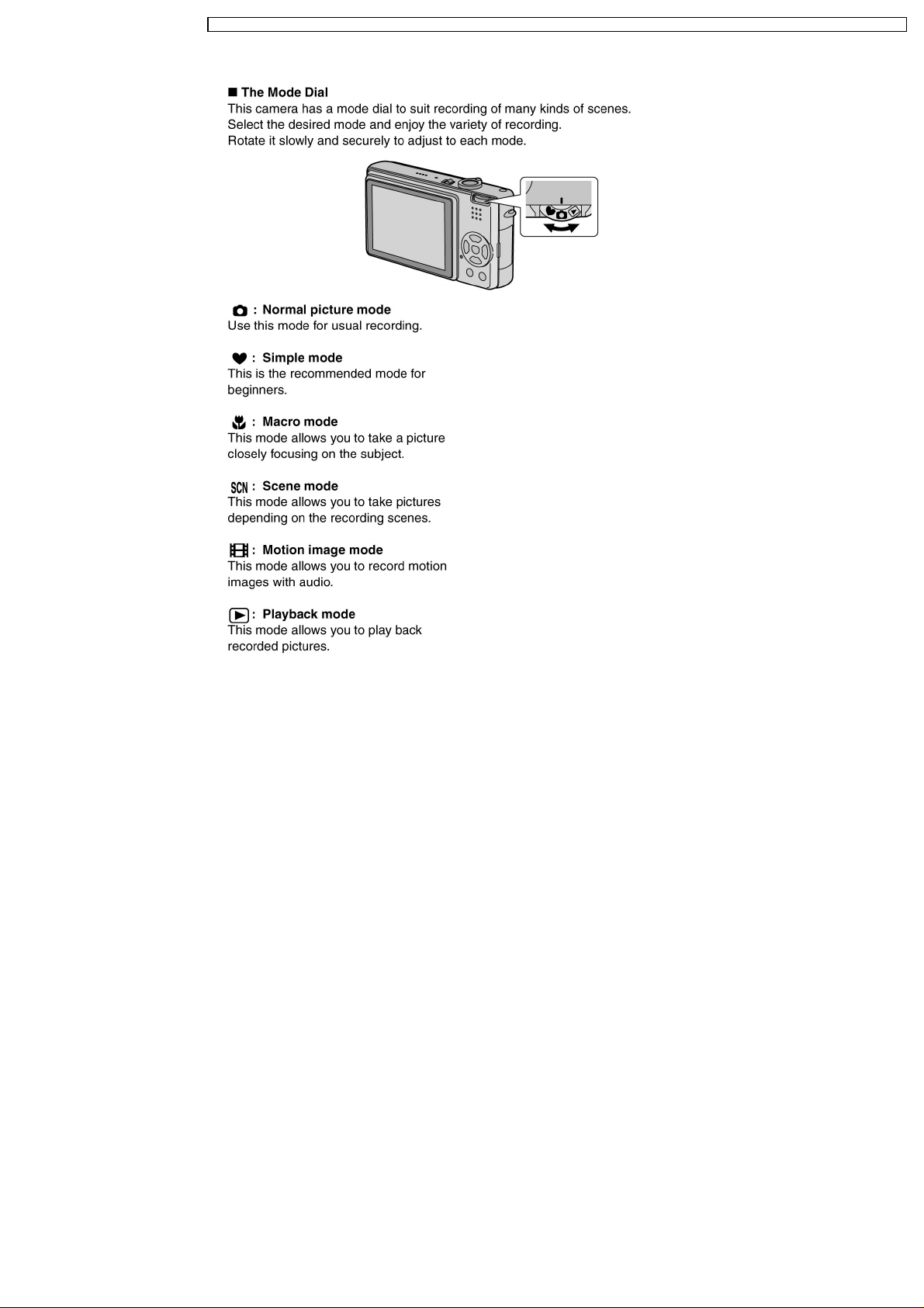
6 OPERATING GUIDE
7 SERVICE NOTES
7.1. WHEN REPLACING THE MAIN C.B.A.
10
10
12
14
14
4
4
4
5
7
7
7
7
8
9
9
9
7.2. SERVICE POSITION
7.3. HOW TO DISCHARGE THE CAPACITOR ON FLASH
TOP C.B.A.
7.4. CLEANING LENS AND LCD PANEL
7.5. NOTE FOR SCHEMATIC DIAGRAM
8 ADJUSTMENT PROCEDURES
8.1. SERVICE FIXTURE AND TOOLS
9 ERROR CODE MEMORY FUNCTION
10 CONFIRMATION OF FIRMWARE VERSION
11 DISASSEMBLY PROCEDURE
11.1. DISASSEMBLY FLOW CHART
11.2. C.B.A. LOCATION
11.3. DIASSEMBLY PROCEDURE
11.4. DISASSEMBLY PROCEDURE FOR THE LENS
11.5. ASSEMBLY PROCEDURE FOR THE LENS
11.6. REMOVAL OF THE CCD
11.7. THE APPLYMENT OF GREASE METHOD
12 SCHEMATIC DIAGRAMS
12.1. OVERALL BLOCK DIAGRAM
12.2. WIRING CONNECTION DIAGRAM
14
15
15
15
16
17
18
21
22
22
22
22
26
29
31
32
33
33
34
2

DMC-FX8PL / DMC-FX8EB / DMC-FX8EF / DMC-FX8EG / DMC-FX8EGM / DMC-FX8GC / DMC-FX8GD / DMC-FX8GK / DMC-FX8GN / DMC-FX8GT / DMC-FX8SG
12.3. SUB SCHEMATIC DIAGRAM 35
12.4. FLASH TOP SCHEMATIC DIAGRAM
12.5. AF ASSIST LED SCHEMATIC DIAGRAM
12.6. CCD SCHEMATIC DIAGRAM
12.7. LENS FLEX SCHEMATIC DIAGRAM
13 CIRCUIT BOARD ASSEMBLIES
13.1. SUB C.B.A.
13.2. FLASH TOP C.B.A.
13.3. AF ASSIST LED C.B.A.
13.4. CCD C.B.A.
41
41
42
42
43
43
45
13.5. LENS FLEX C.B.A.
14 EXPLODE D VIEWS
14.1. FRAME & CASING SECTION
14.2. PACKING PARTS & ACCESSORIES SECTION
15 REPLACEMENT PARTS LIST
15.1. MECHANICAL REPLACEMENT PARTS LIST
15.2. ELECTRICAL REPLACEMENT PARTS LIST
45
46
46
47
47
49
50
50
52
3

DMC-FX8PL / DMC-FX8EB / DMC-FX8EF / DMC-FX8EG / DMC-FX8EGM / DMC-FX8GC / DMC-FX8GD / DMC-FX8GK / DMC-FX8GN / DMC-FX8GT / DMC-FX8SG
1 INTRODUCTION
1.1. INTRODUCTION
This service manual contains technical information, which allow service personnel’s to understand and service this model.
Please place orders using the parts list and not the drawing reference numbers.
If the circuit is changed or modified, the information will be followed by service manual to be controlled with original service manual.
1.2. ABOUT LEAD FREE SOLDER (PbF)
Distinction of PbF PCB:
PCBs (manufactured) using lead free solder will have a PbF stamp on the PCB.
Caution:
· Pb free solder has a higher melting point than standard solder, Typically the melting point is 30-40°C higher.
Please use a high temperature soldering iron. In case of soldering iron with temperature control, please set it to 370±10°C.
· Pb free solder will tend to splash when heated too high (about 600°C).
When soldering or unsoldering, please completely remove all of the solder on the pins or solder area, and be sure to heat the
soldering points with the Pb free solder until it melts enough.
1.3. IMPORTANT NOTICE 1:
1. The service manual does not contain the following information, because of the impossibility of servicing at component level.
a. Schematic diagram, Block Diagram and C.B.A. layout of Main C.B.A.
b. Parts list for individual parts of Main C.B.A.
When a part replacement is required for repairing Main C.B.A., replace as an assembled parts. (Main C.B.A.)
2. The following category is/are recycle module part. please send it/them to Central Repair Center.
· MAIN C.B.A. (VEP56023A) : Excluding replacement of Lithium Battery
4
DMC-FX8PL / DMC-FX8EB / DMC-FX8EF / DMC-FX8EG / DMC-FX8EGM / DMC-FX8GC / DMC-FX8GD / DMC-FX8GK / DMC-FX8GN / DMC-FX8GT / DMC-FX8SG
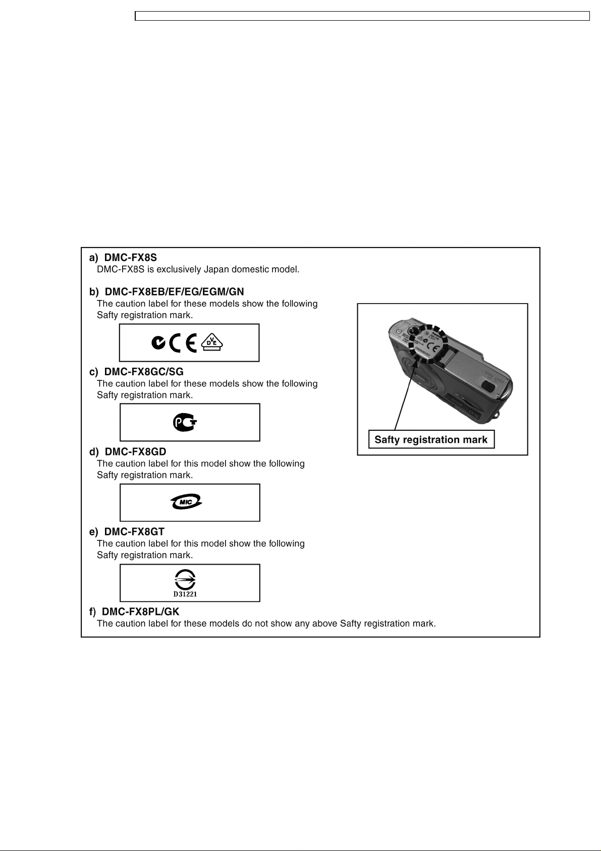
1.4. HOW TO DEFINE THE MODEL SUFFIX (NTSC or PAL model)
There are six kinds of DMC-FX8, regardless of the colours.
· a) DMC-FX8S
· b) DMC-FX8EB/EF/EG/EGM/GN
· c) DMC-FX8GC/SG
· d) DMC-FX8GD
· e) DMC-FX8GT
· f) DMC-FX8PL/GK
(DMC-FX8S is exclusively Japan domestic model.)
What is the difference is that the “INITIAL SETTING” data which is stored in Flash ROM mounted on Main C.B.A.
1.4.1. Defining methods:
To define the model suffix to be serviced, refer to the nameplate which is putted on the bottom side of the Unit.
NOTE:
After replacing the MAIN C.B.A., be sure to achieve adjustment.
The adjustment instruction is available at “software download” on the “Support Information from NWBG-PAVC” web-site in
“TSN system”, together with Maintenance software.
5
DMC-FX8PL / DMC-FX8EB / DMC-FX8EF / DMC-FX8EG / DMC-FX8EGM / DMC-FX8GC / DMC-FX8GD / DMC-FX8GK / DMC-FX8GN / DMC-FX8GT / DMC-FX8SG
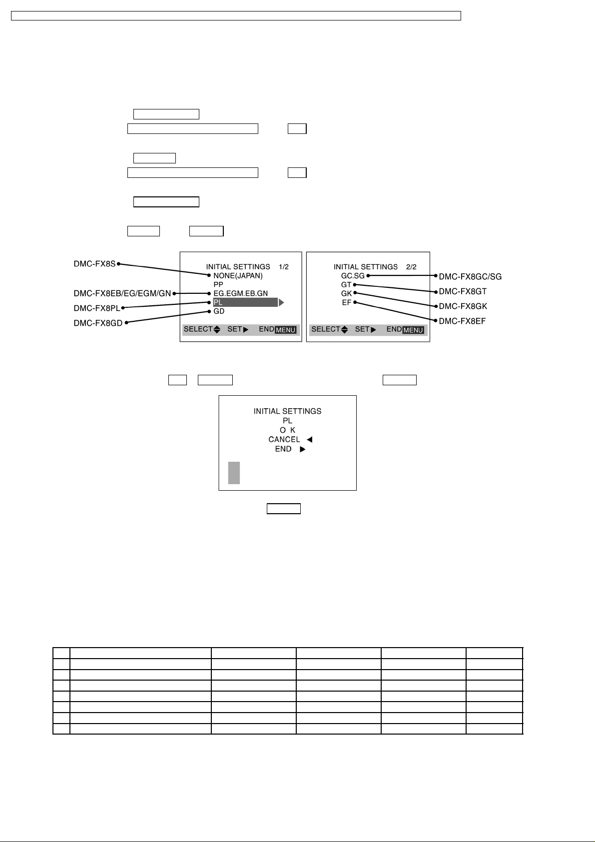
1.4.2. INITIAL SETTINGS:
When you replace the Main C.B.A. be sure to perform the initial settings after achieving the Adjustment, by ordering the following
procedure in accordance with model suffix.
· Step 1. The temporary cancellation of factory setting:
Set the mode dial to “ Normal Picture
While keep pressing Optical Image Stabilizer Button
· Step 2. The cancellation of factory setting:
Set the mode dial to “ Playback
While keep pressing Optical Image Stabilizer Button
· Step 3. Turn the Power on:
Set the mode dial to “ Normal Picture
· Step 4. Display the INITIAL SETTING:
While keep pressing MENU
and “ RIGHT of Cross key” simultaneously, turn the Power off.
(Red camera mark)”.
and “ UP of Cross key” simultaneously, turn the Power on.
”.
and “ UP of Cross key” simultaneously, turn the Power off.
(Red camera mark)”, and then turn the Power on.
· Step 5. Set the INITIAL SETTING:
Select the area with pressing “ UP
/ DOWN of Cross key”, and then press the “ RIGHT of Cross key”.
The only set area is displayed, and then press the “ RIGHT of Cross key” after confirmation. (The unit is powered off
automatically.)
Confirm the display of “PLEASE SET THE CLOCK” in English when the unit is turned on again.
· Step 6. CONFIRMATION:
The display shows “PLEASE SET THE CLOCK” when turn the Power on again.
Connect the unit to PC with USB cable and is detected as removable media.
(For China and Taiwan marker, the display shows “PLEASE SET THE CLOCK” in Chinese.)
1) As for your reference Default setting condition is given in the following table.
· Default setting (After “INITIAL SETTINGS”)
MODEL VIDEO OUTPUT LANGUAGE DATE REMARKS
a) DMC-FX8S NTSC Japanese Year/Month/Date
b) DMC-FX8PL NTSC English Month/Date/Year
c) DMC-FX8EB/EG/EGM/GC/GN/SG PAL English Date/Month/Year
d) DMC-FX8GK PAL Chinese (simplified) Year/Month/Date
e) DMC-FX8GT NTSC Chinese (traditional) Year/Month/Date
f) DMC-FX8GD NTSC English Year/Month/Date
g) DMC-FX8EF NTSC French Date/Month/Year
6
DMC-FX8PL / DMC-FX8EB / DMC-FX8EF / DMC-FX8EG / DMC-FX8EGM / DMC-FX8GC / DMC-FX8GD / DMC-FX8GK / DMC-FX8GN / DMC-FX8GT / DMC-FX8SG
2 SAFETY PRECAUTIONS
2.1. GENERAL GUIDELINES
1. IMPORTANT SAFETY NOTICE
There are special components used in this equipment
which are important for safety. These parts are marked by
in the Schematic Diagrams, Circuit Board Layout,
Exploded Views and Replacement Parts List. It is essential
that these critical parts should be replaced with
manufacturer’s specified parts to prevent X-RADIATION,
shock, fire, or other hazards. Do not modify the original
design without permission of manufacturer.
2. An Isolation Transformer should always be used during the
servicing of AC Adaptor whose chassis is not isolated from
the AC power line. Use a transformer of adequate power
rating as this protects the technician from accidents
resulting in personal injury from electrical shocks. It will also
protect AC Adaptor from being damaged by accidental
shorting that may occur during servicing.
3. When servicing, observe the original lead dress. If a short
circuit is found, replace all parts which have been
overheated or damaged by the short circuit.
4. After servicing, see to it that all the protective devices such
as insulation barriers, insulation papers shields are properly
installed.
5. After servicing, make the following leakage current checks
to prevent the customer from being exposed to shock
hazards.
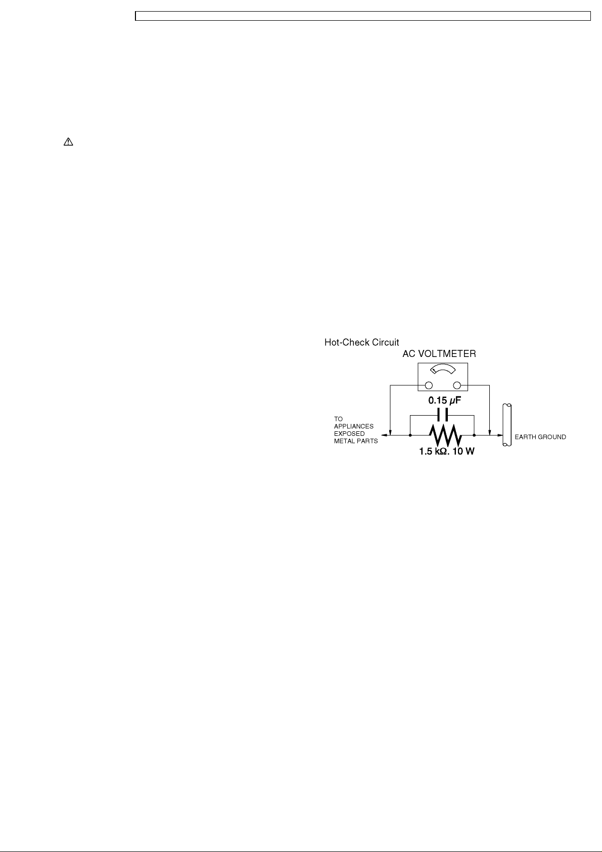
2.3. LEAKAGE CURRENT HOT
CHECK (See Figure 1.)
1. Plug the AC cord directly into the AC outlet. Do not use an
isolation transformer for this check.
2. Connect a 1.5 kΩ, 10 W resistor, in parallel with a 0.15 µF
capacitor, between each exposed metallic part on the set
and a good earth ground, as shown in Figure 1.
3. Use an AC voltmeter, with 1 kΩ/V or more sensitivity, to
measure the potential across the resistor.
4. Check each exposed metallic part, and measure the
voltage at each point.
5. Reverse the AC plug in the AC outlet and repeat each of the
above measurements.
6. The potential at any point should not exceed 0.75 V RMS.
A leakage current tester (Simpson Model 229 or equivalent)
may be used to make the hot checks, leakage current must
not exceed 1/2 mA. In case a measurement is outside of
the limits specified, there is a possibility of a shock hazard,
and the equipment should be repaired and rechecked
before it is returned to the customer.
2.2. LEAKAGE CURRENT COLD
CHECK
1. Unplug the AC cord and connect a jumper between the two
prongs on the plug.
2. Measure the resistance value, with an ohmmeter, between
the jumpered AC plug and each exposed metallic cabinet
part on the equipment such as screwheads, connectors,
control shafts, etc. When the exposed metallic part has a
return path to the chassis, the reading should be between 1
MΩ and 5.2 MΩ. When the exposed metal does not have a
return path to the chassis, the reading must be infinity.
Figure. 1
7

DMC-FX8PL / DMC-FX8EB / DMC-FX8EF / DMC-FX8EG / DMC-FX8EGM / DMC-FX8GC / DMC-FX8GD / DMC-FX8GK / DMC-FX8GN / DMC-FX8GT / DMC-FX8SG
3 PREVENTION OF ELECTRO STATIC DISCHARGE (ESD)
TO ELECTROSTATICALLY SENSITIVE (ES) DEVICES
Some semiconductor (solid state) devices can be damaged easily by static electricity. Such components commonly are called
Electrostatically Sensitive (ES) Devices. Examples of typical ES devices are integrated circuits and some field-effect transistors and
semiconductor "chip" components. The following techniques should be used to help reduce the incidence of component damage
caused by electro static discharge (ESD).
1. Immediately before handling any semiconductor component or semiconductor-equipped assembly, drain off any ESD on your
body by touching a known earth ground. Alternatively, obtain and wear a commercially available discharging ESD wrist strap,
which should be removed for potential shock reasons prior to applying power to the unit under test.
2. After removing an electrical assembly equipped with ES devices, place the assembly on a conductive surface such as
aluminum foil, to prevent electrostatic charge buildup or exposure of the assembly.
3. Use only a grounded-tip soldering iron to solder or unsolder ES devices.
4. Use only an antistatic solder removal device. Some solder removal devices not classified as "antistatic (ESD protected)" can
generate electrical charge sufficient to damage ES devices.
5. Do not use freon-propelled chemicals. These can generate electrical charges sufficient to damage ES devices.
6. Do not remove a replacement ES device from its protective package until immediately before you are ready to install it. (Most
replacement ES devices are packaged with leads electrically shorted together by conductive foam, aluminum foil or comparable
conductive material).
7. Immediately before removing the protective material from the leads of a replacement ES device, touch the protective material
to the chassis or circuit assembly into which the device will be installed.
CAUTION :
Be sure no power is applied to the chassis or circuit, and observe all other safety precautions.
8. Minimize bodily motions when handling unpackaged replacement ES devices. (Otherwise harmless motion such as the
brushing together of your clothes fabric or the lifting of your foot from a carpeted floor can generate static electricity (ESD)
sufficient to damage an ES device).
8
DMC-FX8PL / DMC-FX8EB / DMC-FX8EF / DMC-FX8EG / DMC-FX8EGM / DMC-FX8GC / DMC-FX8GD / DMC-FX8GK / DMC-FX8GN / DMC-FX8GT / DMC-FX8SG
4 CAUTION FOR AC CORD
(EB/GC/SG only)
4.1. INFORMATION FOR YOUR
SAFETY
IMPORTANT
Your attention is drawn to the fact that recording of prerecorded tapes or discs or other published or broadcast
material may infringe copyright laws.
WARNING
To reduce the risk of fire or shock hazard, do not expose
this equipment to rain or moisture.
CAUTION
To reduce the risk of fire or shock hazard and annoying
interference, use the recommended accessories only.
FOR YOUR SAFETY
DO NOT REMOVE THE OUTER COVER
To prevent electric shock, do not remove the cover. No user
serviceable parts inside. Refer servicing to qualified service
personnel.
4.2.1. Important
The wires in this mains lead are coloured in accordance with
the following code:
Blue Neutral
Brown Live
As the colours of the wires in the mains lead of this appliance
may not correspond with the coloured markings identifying the
terminals in your plug, proceed as follows:
The wire which is coloured BLUE must be connected to the
terminal in the plug which is marked with the letter N or
coloured BLACK.
The wire which is coloured BROWN must be connected to the
terminal in the plug which is marked with the letter L or coloured
RED.
Under no circumstances should either of these wires be
connected to the earth terminal of the three pin plug, marked
with the letter E or the Earth Symbol.
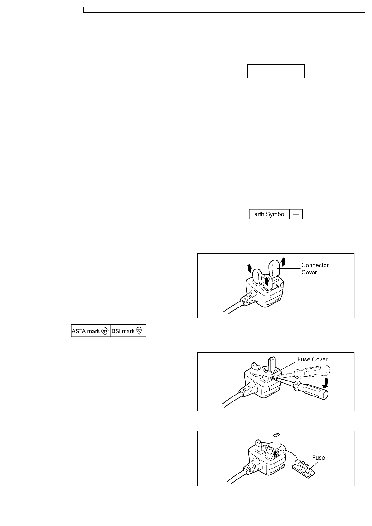
4.2. CAUTION FOR AC MAINS
LEAD
For your safety, please read the following text carefully.
This appliance is supplied with a moulded three-pin mains plug
for your safety and convenience.
A 5-ampere fuse is fitted in this plug.
Should the fuse need to be replaced please ensure that the
replacement fuse has a rating of 5 amperes and it is approved
by ASTA or BSI to BS1362
Check for the ASRA mark or the BSI mark on the body of the
fuse.
If the plug contains a removable fuse cover you must ensure
that it is refitted when the fuse is replaced.
If you lose the fuse cover, the plug must not be used until a
replacement cover is obtained.
A replacement fuse cover can be purchased from your local
Panasonic Dealer.
4.2.2. Before use
Remove the Connector Cover as follows.
4.2.3. How to replace the Fuse
1. Remove the Fuse Cover with a screwdriver.
If the fitted moulded plug is unsuitable for the socket outlet in
your home then the fuse should be removed and the plug cut
off and disposed of safety.
There is a danger of severe electrical shock if the cut off plug
is inserted into any 13-ampere socket.
If a new plug is to be fitted please observe the wiring code as
shown below.
If in any doubt, please consult a qualified electrician.
2. Replace the fuse and attach the Fuse cover.
9
DMC-FX8PL / DMC-FX8EB / DMC-FX8EF / DMC-FX8EG / DMC-FX8EGM / DMC-FX8GC / DMC-FX8GD / DMC-FX8GK / DMC-FX8GN / DMC-FX8GT / DMC-FX8SG
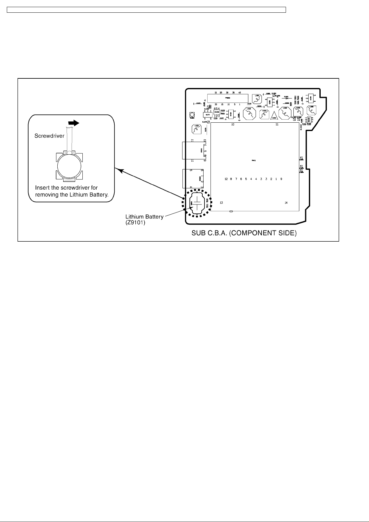
5 HOW TO REPLACE THE LITHIUM BATTERY
5.1. REPLACEMENT PROCEDURE
1. Remove the SUB C.B.A. (Refer to Disassembly Procedures.)
2. Remove the Lithium battery (Ref. No. “Z9101” at component side of SUB C.B.A.) and then replace it into new one.
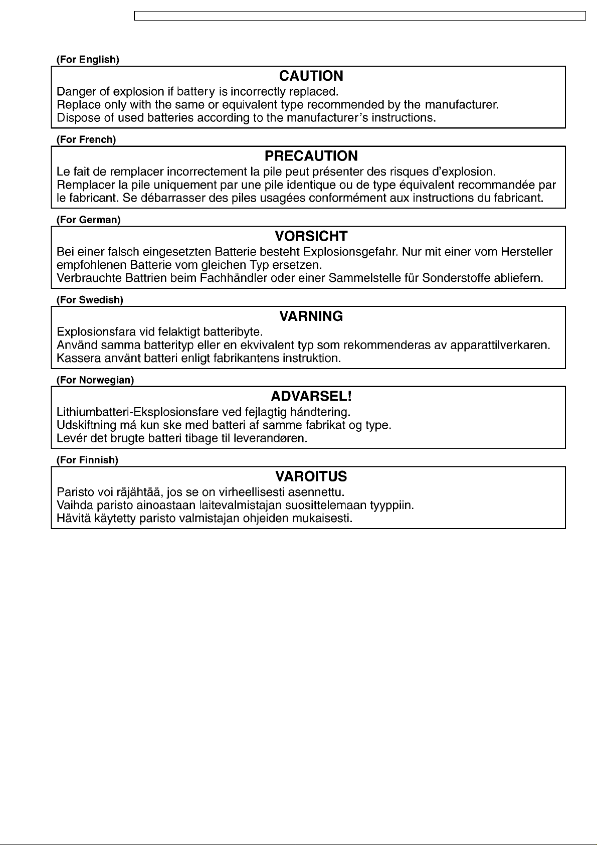
NOTE:
This Lithium battery is a critical component.
(Type No.: ML-421S/ZT Manufactured by Matsushita Battery Industrial Co.,Ltd.)
It must never be subjected to excessive heat or discharge.
It must therefore only be fitted in requirement designed specifically for its use.
Replacement batteries must be of same type and manufacture.
They must be fitted in the same manner and location as the original battery, with the correct polarity contacts observed.
Do not attempt to re-charge the old battery or re-use it for any other purpose.
It should be disposed of in waste products destined for burial rather than incineration.
10
DMC-FX8PL / DMC-FX8EB / DMC-FX8EF / DMC-FX8EG / DMC-FX8EGM / DMC-FX8GC / DMC-FX8GD / DMC-FX8GK / DMC-FX8GN / DMC-FX8GT / DMC-FX8SG
NOTE:
Above caution is applicable for a battery pack which is for DMC-FX8 series, as well.
11
DMC-FX8PL / DMC-FX8EB / DMC-FX8EF / DMC-FX8EG / DMC-FX8EGM / DMC-FX8GC / DMC-FX8GD / DMC-FX8GK / DMC-FX8GN / DMC-FX8GT / DMC-FX8SG
6 OPERATING GUIDE
12
DMC-FX8PL / DMC-FX8EB / DMC-FX8EF / DMC-FX8EG / DMC-FX8EGM / DMC-FX8GC / DMC-FX8GD / DMC-FX8GK / DMC-FX8GN / DMC-FX8GT / DMC-FX8SG
13
DMC-FX8PL / DMC-FX8EB / DMC-FX8EF / DMC-FX8EG / DMC-FX8EGM / DMC-FX8GC / DMC-FX8GD / DMC-FX8GK / DMC-FX8GN / DMC-FX8GT / DMC-FX8SG
7 SERVICE NOTES
7.1. WHEN REPLACING THE MAIN C.B.A.
After replacing the MAIN C.B.A., be sure to achieve adjustment.
The adjustment instruction is available at “software download” on the “Support Information from NWBG-PAVC” web-site in “TSN
system”, together with Maintenance software.
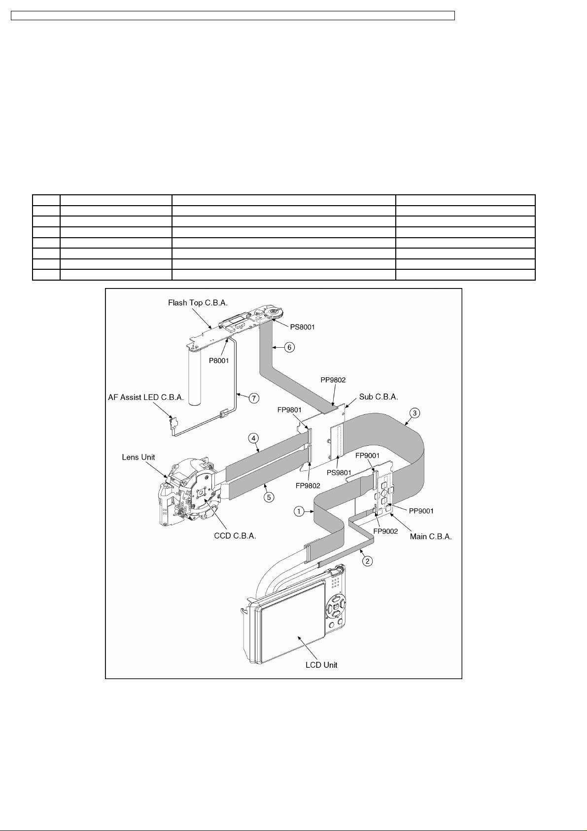
7.2. SERVICE POSITION
This Service Position is used for checking and replacing parts. Use the following Extension cables for servicing.
No. Parts No. Connection Form
1 VFK1284 FP9001 (MAIN) - LCD UNIT 24PIN 0.5 FFC
2 VFK1974 FP9002 (MAIN) - LCD UNIT 4PIN 0.5 FFC
3 VFK1973 PP9001 (MAIN) - PS9801 (SUB) 120PIN B to B
4 VFK1950 FP9801 (SUB) - CCD UNIT 33PIN 0.5 FFC
5 VFK1951 FP9802 (SUB) - LENS UNIT 39PIN 0.5 FFC
6 VFK1541 PP9802 (SUB) - PS8001 (FLASH TOP) 40PIN B to B
7 VFK1576DSC04 P8001 (FLASH TOP) - AF ASSIST LED C.B.A. 2PIN CONNECTOR
Table S1 Extension Cable List
CAUTION-1. (When servicing FLASH TOP C.B.A.)
1. Be sure to discharge the capacitor on FLASH TOP C.B.A.
Refer to “HOW TO DISCHARGE THE CAPACITOR ON FLASH TOP C.B.A.”.
The capacitor voltage is not lowered soon even if the AC Cord is unplugged or the battery is removed.
2. Be careful of the high voltage circuit on FLASH TOP C.B.A.
3. DO NOT allow other parts to touch the high voltage circuit on FLASH TOP C.B.A.
14
DMC-FX8PL / DMC-FX8EB / DMC-FX8EF / DMC-FX8EG / DMC-FX8EGM / DMC-FX8GC / DMC-FX8GD / DMC-FX8GK / DMC-FX8GN / DMC-FX8GT / DMC-FX8SG
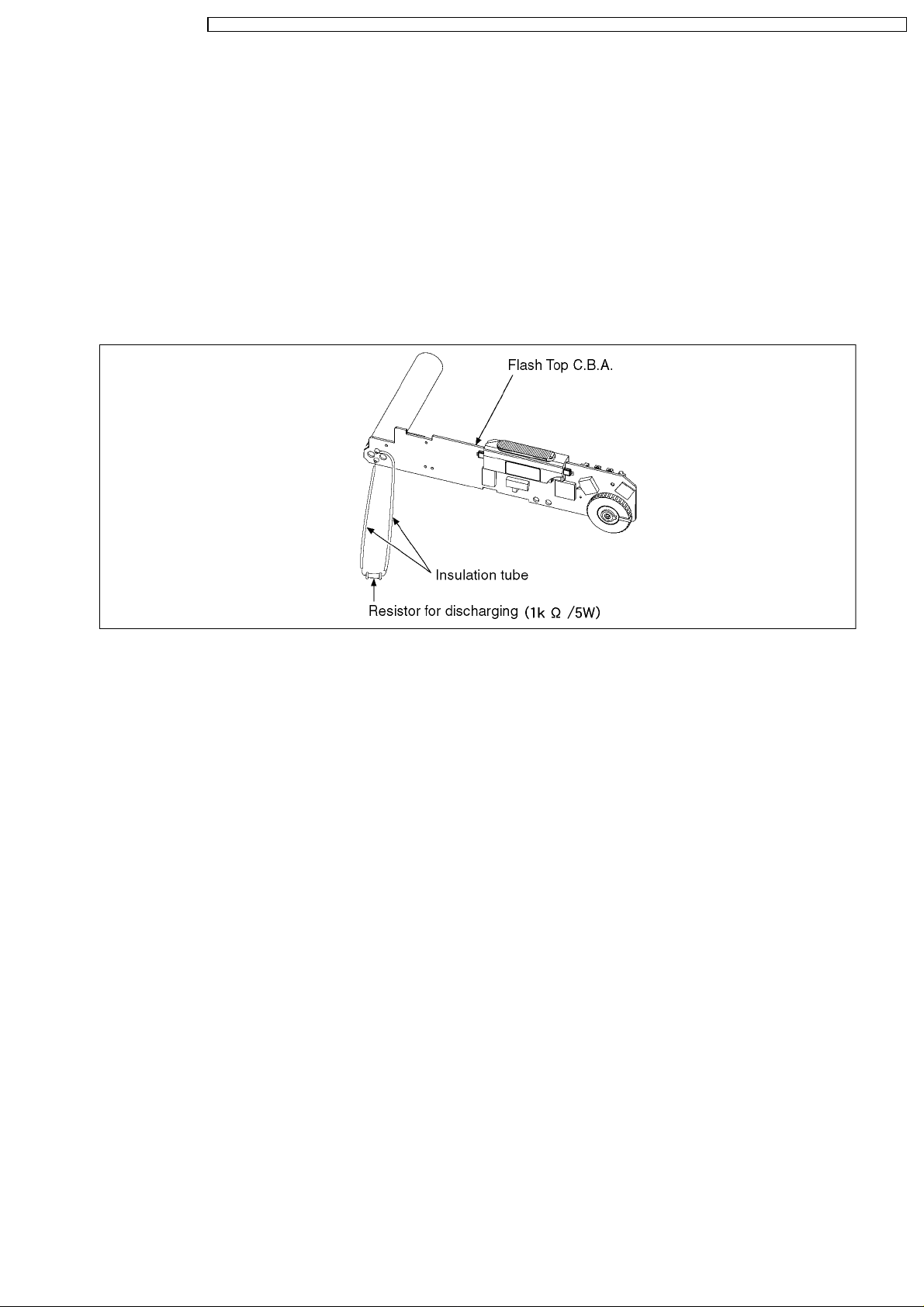
7.3. HOW TO DISCHARGE THE CAPACITOR ON FLASH TOP C.B.A.
CAUTION:
1. Be sure to discharge the capacitor on FLASH TOP C.B.A.
2. Be careful of the high voltage circuit on FLASH TOP C.B.A. when servicing.
[Discharging Procedure]
1. Refer to the disassemble procedure and Remove the necessary parts/unit.
2. Put the insulation tube onto the lead part of Resistor (ERG5SJ102:1kΩ /5W).
(an equivalent type of resistor may be used.)
3. Put the resistor between both terminals of capacitor on FLASH TOP C.B.A. for approx. 5 seconds.
4. After discharging confirm that the capacitor voltage is lower than 10V using a voltmeter.
Fig. F1
7.4. CLEANING LENS AND LCD PANEL
Do not touch the surface of lens and LCD Panel with your hand.
When cleaning the lens, use air-Blower to blow off the dust.
When cleaning the LCD Panel, dampen the lens cleaning paper with lens cleaner, and the gently wipe the their surface.
Note:
A lens cleaning paper and lens cleaner are available at local camera shops and market place.
7.5. NOTE FOR SCHEMATIC DIAGRAM
[Circuit voltage and waveform]
Circuit voltage and waveform described herein shall be regarded as reference information when probing defect point, because
it may differ from an actual measuring value due to difference of Measuring instrument and its measuring condition and product
itself.
15
DMC-FX8PL / DMC-FX8EB / DMC-FX8EF / DMC-FX8EG / DMC-FX8EGM / DMC-FX8GC / DMC-FX8GD / DMC-FX8GK / DMC-FX8GN / DMC-FX8GT / DMC-FX8SG
8 ADJUSTMENT PROCEDURES
Even if the MAIN C.B.A. is replaced as a unit, it must be achieved the adjustment and factory setting. The adjustment in
this unit is separated two types as shown below.
The adjustment instruction is available at "Software download" on the CS-Web from AVC" web-site in "TSN System".
1. Main unit adjustment: All adjustments except for LCD adjustment.
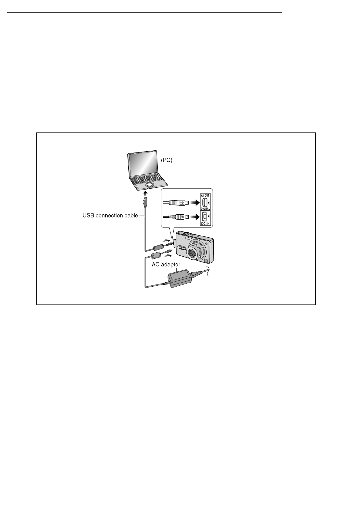
This unit mounts the adjustment software for main unit, it wouldn’t need the connection between the PC and this unit with USB
cable.
2. LCD adjustment: Adjustment for LCD.
It need the connection between the PC and this unit with USB cable.
The adjustment instruction is available at "Software download" on the CS-Web from AVC" web-site in "TSN System", together
with maintenance software.
16
DMC-FX8PL / DMC-FX8EB / DMC-FX8EF / DMC-FX8EG / DMC-FX8EGM / DMC-FX8GC / DMC-FX8GD / DMC-FX8GK / DMC-FX8GN / DMC-FX8GT / DMC-FX8SG
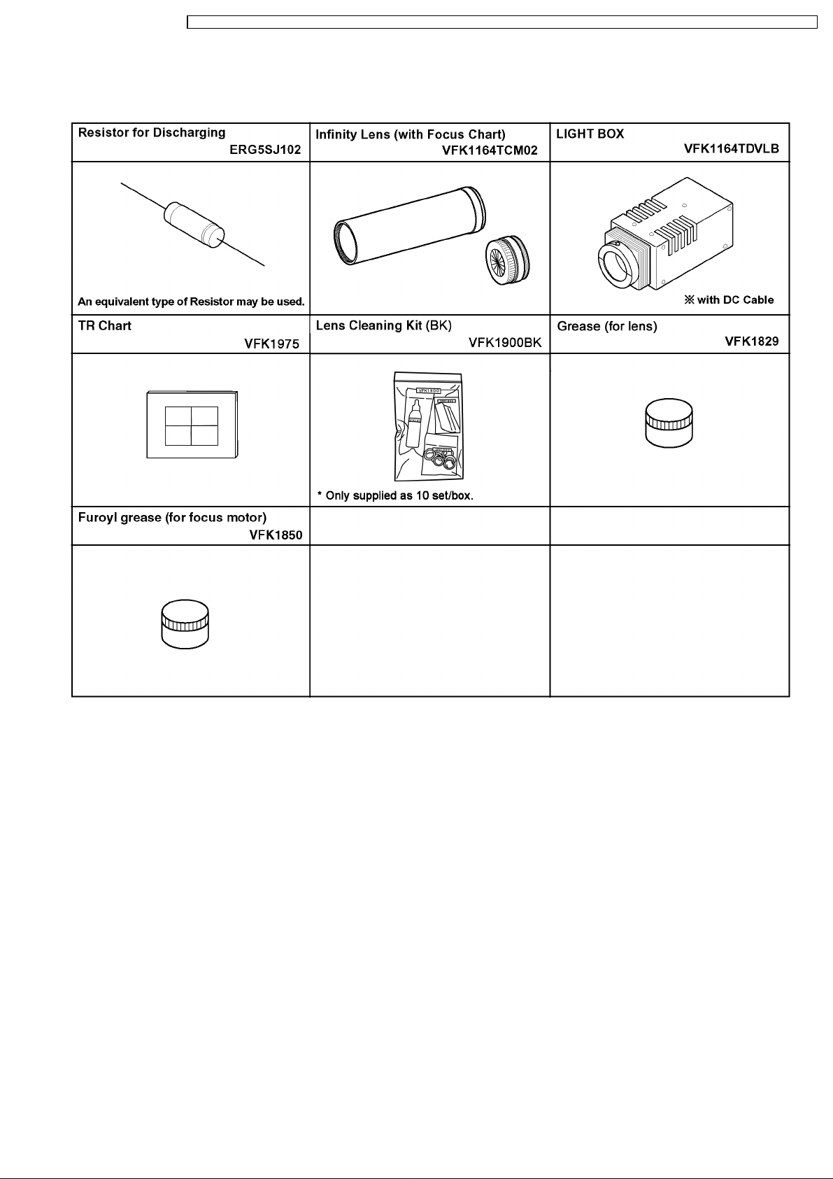
8.1. SERVICE FIXTURE AND TOOLS
The following Service Fixture and tools are used for checking and servicing this unit.
17
 Loading...