

Sony DHC-MD500, DHC-RX707 User Manual

3-864-057-11(1)
Mini Hi-Fi
Component
System
Operating Instructions
Owner’s Record
The model and serial numbers are located on the rear panel. Record the serial
number in the space provided below. Refer to them whenever you call upon your
Sony dealer regarding this product.
Model No. Serial No.
f
DHC-MD500
DHC-RX707
©1998 by Sony Corporation
1
WARNING
To prevent fire or shock hazard, do not
expose the unit to rain or moisture.
To avoid electrical shock, do not open the cabinet.
Refer servicing to qualified personnel only.
Do not install the appliance in a confined space,
such as a bookcase or built-in cabinet.
Laser component in this product is capable of
emitting radiation exceeding the limit for Class 1.
This appliance is classified
as a CLASS 1 LASER
product. The CLASS 1
LASER PRODUCT
MARKING is located on
the rear exterior.
This caution label is located inside the unit.
NOTICE FOR THE CUSTOMERS IN THE
U.S.A.
This symbol is intended to alert the
user to the presence of uninsulated
“dangerous voltage” within the
product’s enclosure that may be of
sufficient magnitude to constitute a
risk of electric shock to persons.
This symbol is intended to alert the
user to the presence of important
operating and maintenance (servicing)
instructions in the literature
accompanying the appliance.
CAUTION
The use of optical instruments with this product will
increase eye hazard.
INFORMATION
This equipment has been tested and found to
comply with the limits for a Class B digital device,
pursuant to Part 15 of the FCC Rules. These limits
are designed to provide reasonable protection
against harmful interference in a residential
installation. This equipment generates, uses, and can
radiate radio frequency energy and, if not installed
and used in accordance with the instructions, may
cause harmful interference to radio
communications. However, there is no guarantee
that interference will not occur in a particular
installation. If this equipment does cause harmful
interference to radio or television reception, which
can be determined by turning the equipment off and
on, the user is encouraged to try to correct the
interference by one or more of the following
measures:
– Reorient or relocate the receiving antenna.
– Increase the separation between the equipment
and receiver.
– Connect the equipment into an outlet on a circuit
different from that to which the receiver is
connected.
– Consult the dealer or an experienced radio/TV
technician for help.
CAUTION
You are cautioned that any changes or modifications
not expressly approved in this manual could void
your authority to operate this equipment.
NOTICE FOR THE CUSTOMERS IN
CANADA
CAUTION:
TO PREVENT ELECTRIC SHOCK, DO NOT USE
THIS POLARIZED AC PLUG WITH AN
EXTENSION CORD,
RECEPTACLE OR OTHER OUTLET UNLESS THE
BLADES CAN BE FULLY INSERTED TO PREVENT
BLADE EXPOSURE.
This stereo system is equipped with the Dolby Btype noise reduction system*.
* Manufactured under license from Dolby
Laboratories Licensing Corporation.
DOLBY and the double-D symbol a are
trademarks of Dolby Laboratories Licensing
Corporation.
2

Table of Contents
Getting Started
Step 1: Hooking up the system............ 4
Step 2: Setting the time ......................... 6
Step 3: Presetting radio stations .......... 7
Connecting optional AV components . 9
Basic Operations
Playing a CD ......................................... 12
Recording a CD .................................... 14
Listening to the radio........................... 15
Recording from the radio .................... 16
Playing a tape........................................ 17
Recording from a tape ......................... 19
The CD Player
Using the CD display........................... 20
Playing the CD tracks repeatedly ...... 21
Playing the CD tracks in random
order ................................................ 22
Programming the CD tracks ............... 23
Playing CDs without interruption ..... 24
The Tape Deck
Recording on a tape manually ........... 25
Recording a CD by specifying track
order ................................................ 26
Sound Adjustment
Adjusting the sound ............................ 29
Selecting the audio emphasis ............. 30
Selecting the surround effect .............. 31
Other Features
Using the Radio Data System
(RDS)* .............................................. 32
Singing along: Karaoke ...................... 34
Falling asleep to music ........................ 36
Waking up to music ............................. 36
Timer-recording radio programs ....... 38
Additional Information
Precautions ............................................ 40
Troubleshooting ................................... 41
Specifications ........................................ 44
Index....................................................... 46
* European model only
About This Manual
These Operating Instructions explain how to
operate the Mini Hi-Fi Component System. For
information on connecting and operating the
supplied MD deck MDS-S707, please refer to the
separate MDS-S707 Operating Instructions.
DJ Effects
Looping part of a CD ........................... 28
Flashing part of a CD ........................... 28
3
Getting Started
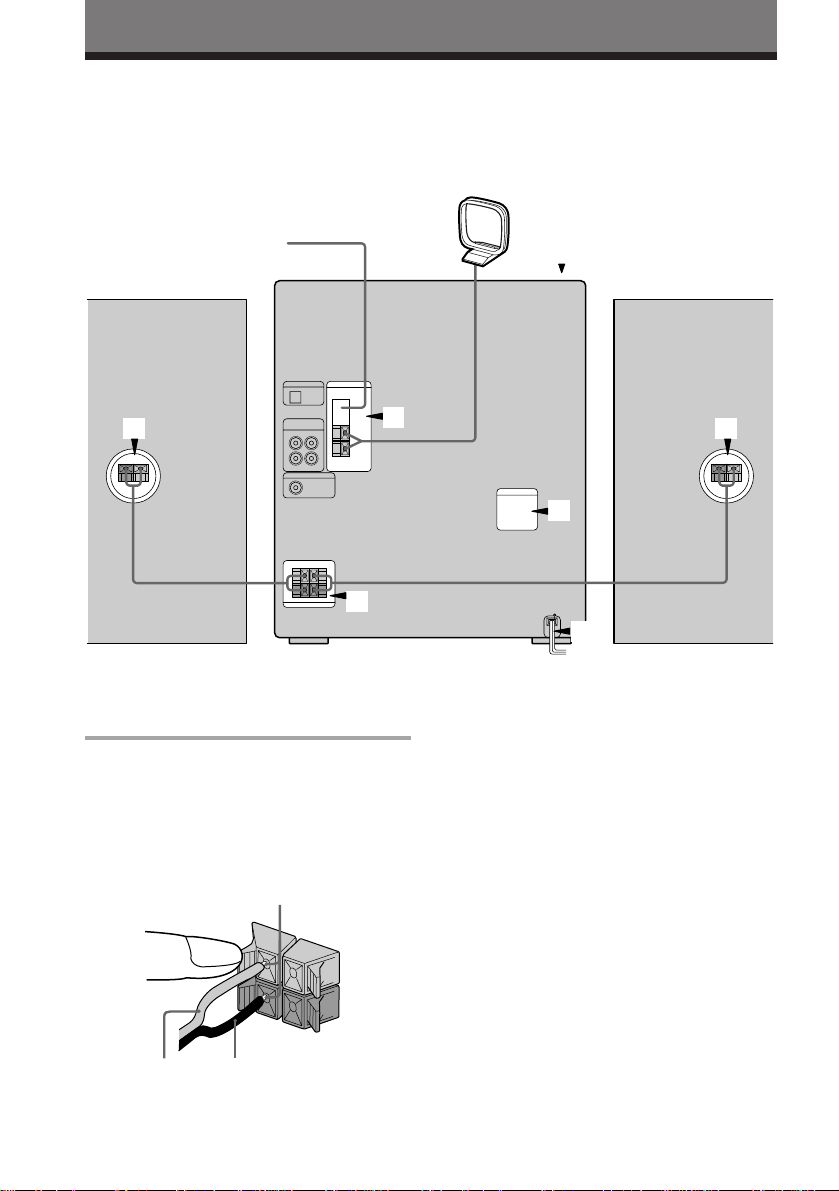
Step 1: Hooking up the system
Do the following procedure 1 to 5 to hook up your system using the supplied cords and
accessories.
AM loop antenna
FM antenna
5
1
Front speaker
(Right)
Connect the speakers.
1
Connect the speaker cords of front
speakers to the SPEAKER jacks of the
same color .
Keep the speaker cords away from the
antennas to prevent noise.
Insert only the stripped portion.
R
+
1
L
+
–
2
1
3
4
Front speaker
(Left)
Note
The type of speakers supplied vary
according to the model you purchased
(see "Specifications" on page 44).
Black (’)Red (‘)
4
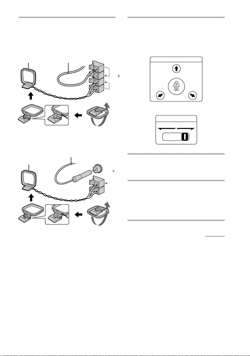
Connect the FM/AM antennas.
2
Set up the AM loop antenna, then
connect it.
Jack type A
Extend the FM lead
AM loop antenna
antenna horizontally.
Set VOLTAGE SELECTOR to
3
position of your local power line
voltage (for models with a voltage
selector).
Selector type A
VOLTAGE SELECTOR
Jack type B
AM loop antenna
Extend the FM lead
antenna horizontally.
FM75
AM
FM75
COAXIAL
AM
240V
-
230
120V
220V
Selector type B
VOLTAGE SELECTOR
110-120V 220-240V
Connect the power cord to a wall
4
outlet.
Demo mode appears in the display.
Deactivate the demo mode by
5
pressing DISPLAY/DEMO when
the system power is turned off.
The demo mode is also deactivated
when you set the time.
continued
5
Step 1: Hooking up the system
(continued)
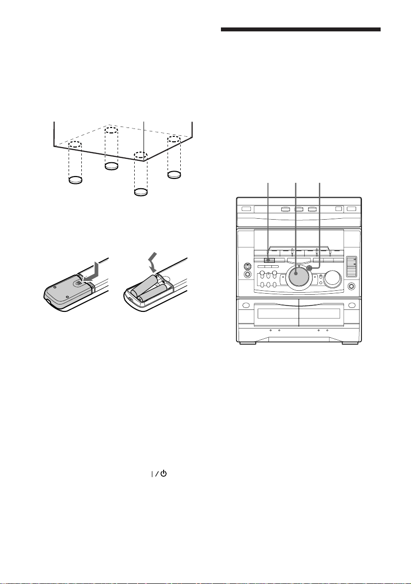
To attach the front speaker pads
Attach the supplied front speaker pads to the
bottom of the speakers to stabilize the
speakers and prevent them from slipping.
Step 2: Setting the
time
You must set the time before using the timer
functions.
The clock is on a 24-hour system for the
European models, and a 12-hour system for
other models.
The 12-hour system model is used for
illustration purposes.
Inserting two size AA (R6)
batteries into the remote
]
}
}
]
Tip
With normal use, the batteries should last for about
six months. When the remote no longer operates
the system, replace both batteries with new ones.
Note
If you do not use the remote for a long period of
time, remove the batteries to avoid possible damage
from battery leakage.
When carrying this system
Do the following to protect the CD
mechanism.
1 Press FUNCTION repeatedly until “CD”
appears in the display.
2 Hold down LOOP and press so that
"LOCK" appears in the display.
1
3,52,4
6
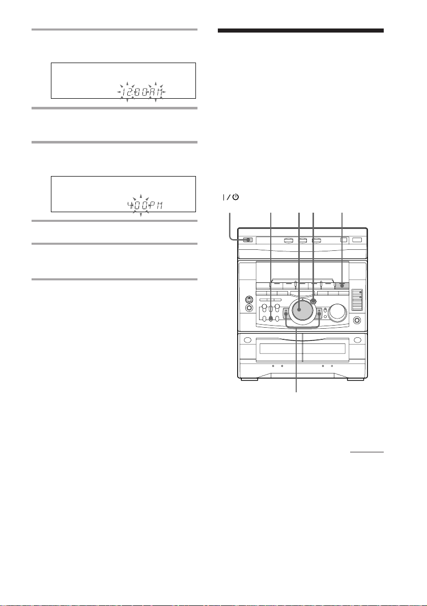
1 Press CLOCK/TIMER SET.
The hour indication flashes.
2 Turn the jog dial to set the hour.
3 Press ENTER/NEXT.
The minute indication flashes.
Step 3: Presetting
radio stations
You can preset the following number of
stations:
– 2 band model: 20 for FM, 10 for AM.
– 3 band model: 20 for FM, 10 for MW, and
10 for SW (or LW, depending on the model
you purchased).
– 4 band model: 20 for FM, 10 for MW, 10 for
LW, and 5 for UKV.
4 Turn the jog dial to set the minute.
5 Press ENTER/NEXT.
The clock starts working.
Tips
• If you’ve made a mistake, start over from step 1.
• Setting the time deactivates the demo mode.
If you want to display the demo mode, press
DISPLAY/DEMO when the power is off.
Note
The previous explanation shows you how to set the
time while the power is off. To change the time
while the power is on, do the following:
1 Press CLOCK/TIMER SET.
2 Turn the jog dial to select SET CLOCK.
3 Press ENTER/NEXT.
4 Perform steps 2 through 5 above.
(Power)
3
541
2
continued
7
VOLUME
ALL DISCS
ß
Step 3: Presetting radio stations
(continued)
1 Press TUNER/BAND repeatedly
until the band you want appears in
the display.
The bands you can receive vary
depending on the model you purchased.
Be sure to check which bands you can
receive.
Every time you press this button, the
band changes as follows:
2 band model:
FM ˜ AM
3 band model:
FM n MW n SW
n
or
FM n MW n LW
n
4 band model:
FM n MW n LW n UKV*
n
* “STEREO PLUS” is displayed when
you select UKV.
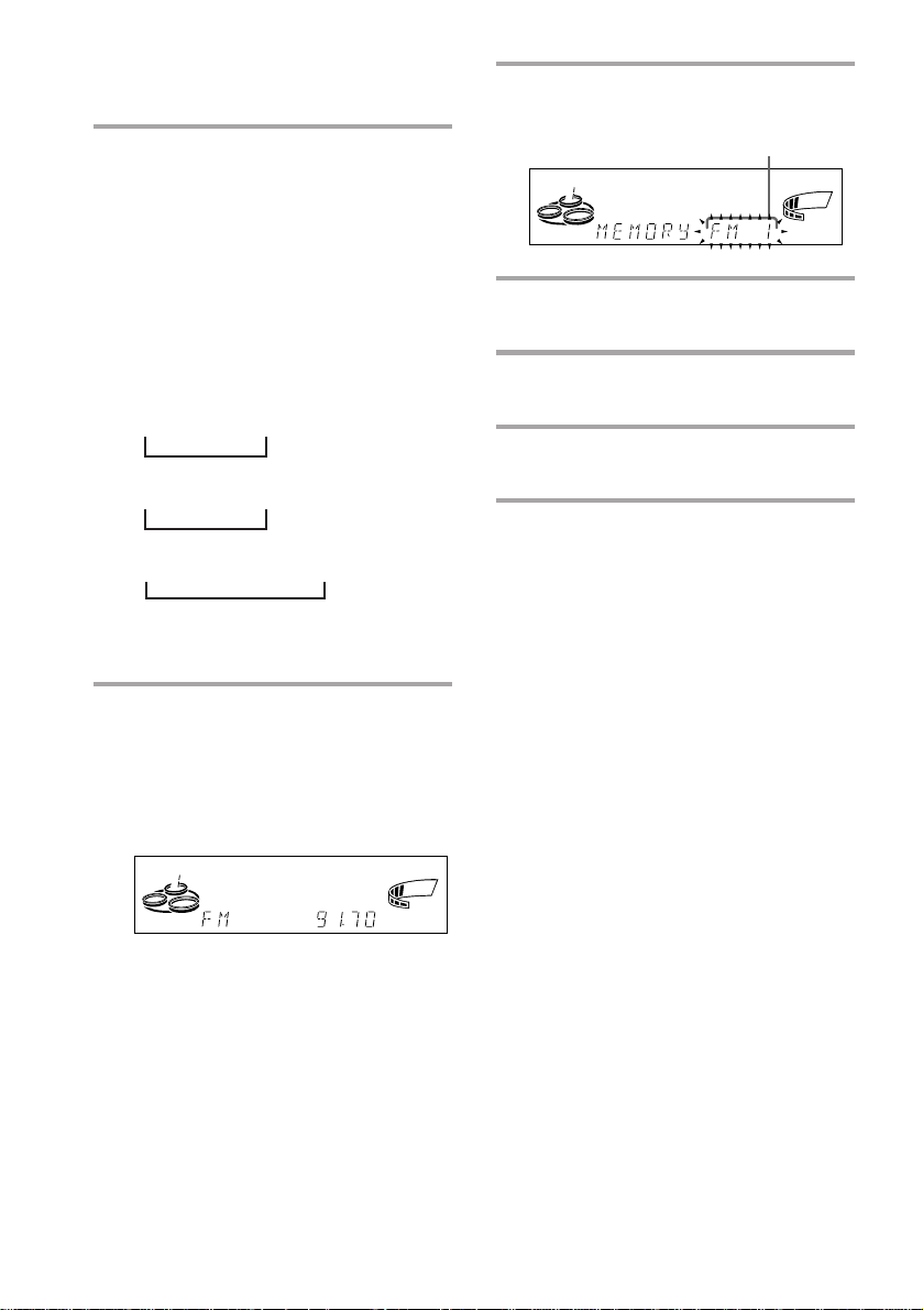
2 Press and hold + or – until the
frequency indication starts to
change, then release.
Scanning stops when the system tunes in
a station. “TUNED” and “STEREO” (for
a stereo program) appear.
TUNED
MONO
STEREO
ALL DISCS
kHz
MHz
VOLUME
3 Press TUNER MEMORY.
A preset number appears in the display.
Preset number
4 Turn the jog dial to select the preset
number you want.
5 Press ENTER/NEXT.
The station is stored.
6 Repeat steps 1 to 5 to store other
stations.
To tune in a station with a weak
signal
Press + or – repeatedly in step 2 to tune in the
station manually.
To change the preset number
Start over from step 1.
To change the AM tuning interval
(Except for the European models)
The AM tuning interval is factory set to 9 kHz (10
kHz in some areas). To change the AM tuning
interval, tune in any AM station first, then turn off
the power. While holding down the ENTER/NEXT
button, turn the power back on. When you change
the interval, AM preset stations will be erased. To
reset the interval, repeat the same procedure.
Tip
The preset stations are retained for half a day even if
ß
you unplug the power cord or if a power failure
occurs.
8
Connecting optional
AV components
To enhance your system, you can connect
optional components. Refer to the
instructions of each component.
Connecting audio
components
Select one of the following two connections,
depending on the equipment to be connected
and method of connecting.
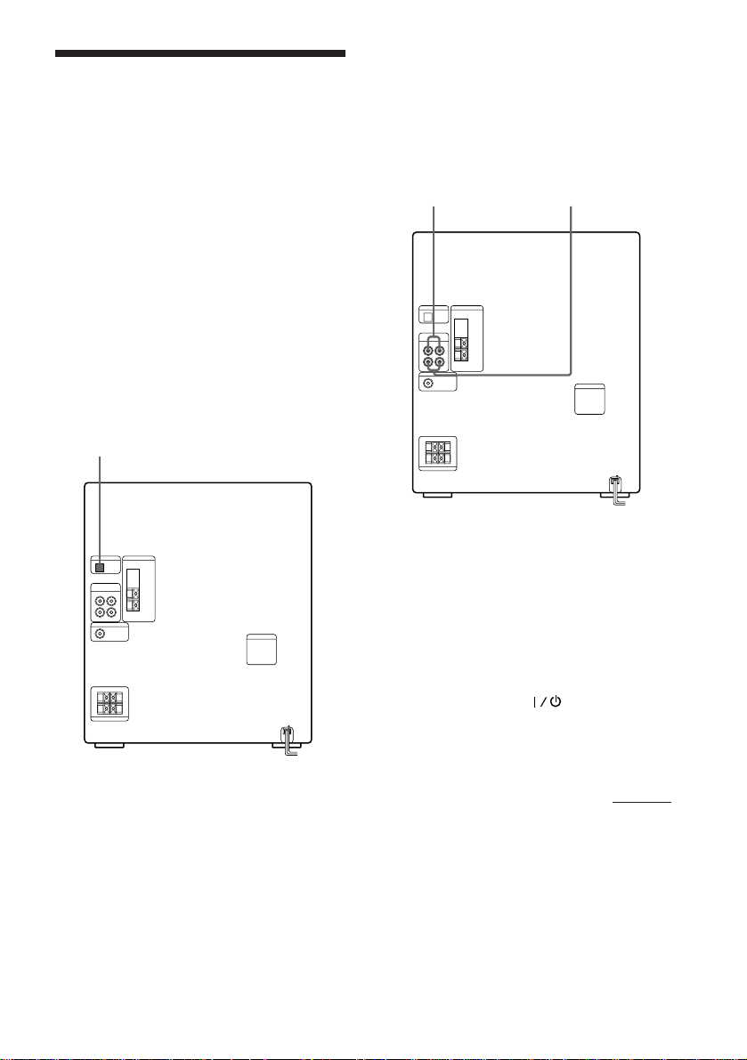
Connecting an MD deck for digital
recording
You can record from CD into the MD deck
digitally by connecting an optical cable.
To the DIGITAL IN jack of the MD deck
Connecting an MD deck for analog
recording
Make sure to match the color of the plugs and
the connectors. To listen to the sound of the
connected MD deck, press FUNCTION
repeatedly until “MD” appears.
To the audio output
of the MD deck
Tip
When you connect a Sony MD deck, you can use the
MD buttons on this unit’s remote to operate it. In
addition, pressing MD · when the power is off,
automatically turns the MD deck on and starts
playback if there is a MD in the deck (One Touch
Play).
To the audio input
of the MD deck
Note
If you cannot select “MD” even when you have
pressed FUNCTION, press
FUNCTION when the power is turned off.
“VIDEO” will be switched to “MD”. To return to
“VIDEO” do the same procedure.
while pressing
continued
9
Connecting optional AV
components (continued)
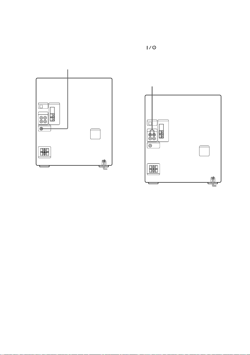
Connecting a super woofer
speaker (DHC-MD500 only)
You can connect an optional super woofer
speaker.
To super woofer
Connecting a VCR
Make sure to match the color of the plugs and
the connectors. To listen to the sound of the
connected VCR, hold down FUNCTION and
press when the power is turned off. This
switches the “MD” function to “VIDEO”.
Once you enable the “VIDEO” function, just
press FUNCTION repeatedly until “VIDEO”
appears.
To the audio output of the VCR
10
Note
If the sound is distorted when selecting “VIDEO”,
or you want to switch back to “MD”, repeat the
operation described above for switching to
“VIDEO”.
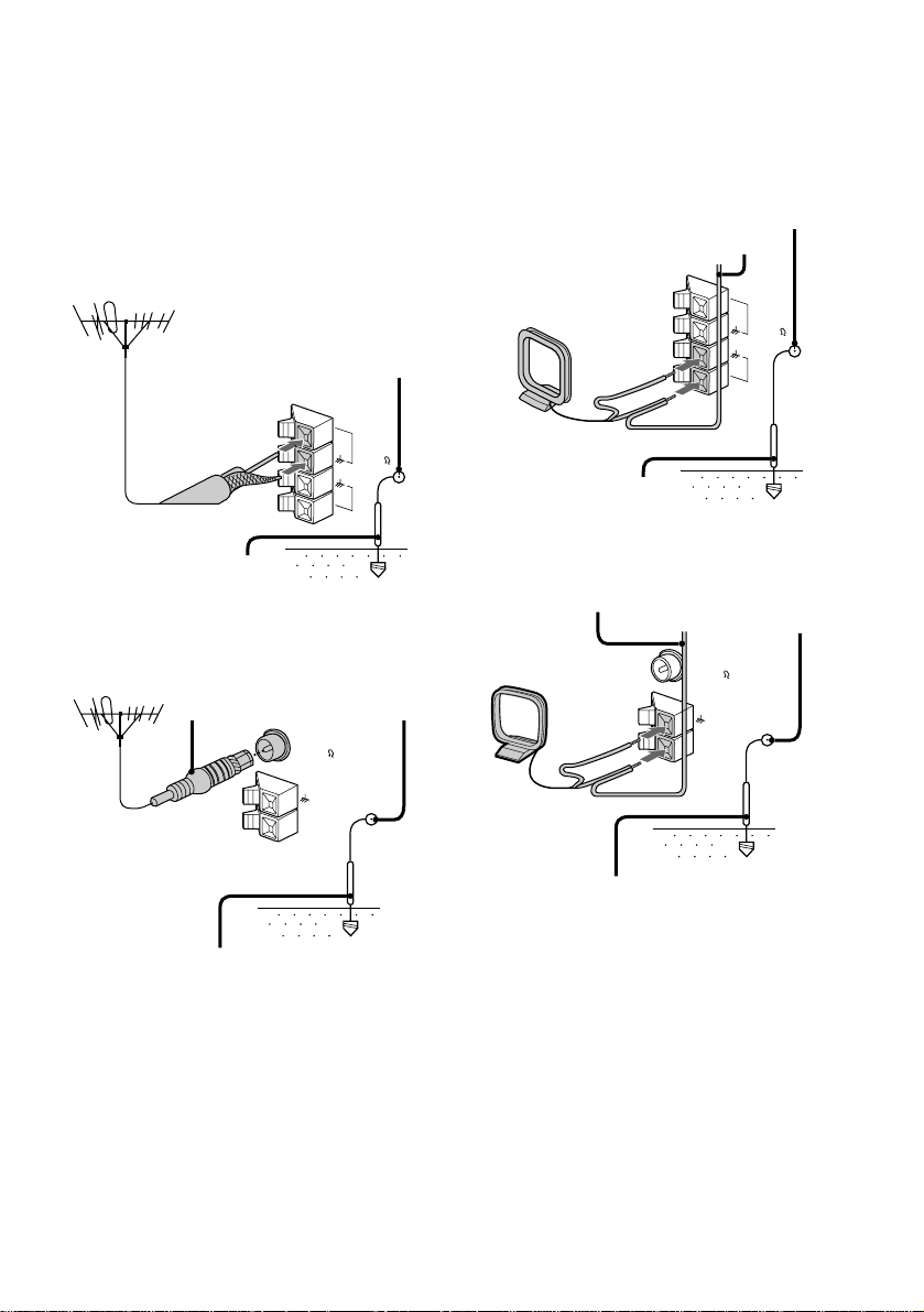
Connecting outdoor
antennas
Connect the outdoor antenna to improve the
reception.
FM antenna
Connect the optional FM outdoor antenna.
You can also use the TV antenna instead.
Jack type A
AM antenna
Connect a 6- to 15- meter (20- to 50- feet)
insulated wire to the AM antenna terminal.
Leave the supplied AM loop antenna
connected.
Jack type A
Screw clamp
Insulated wire (not supplied)
FM75
75-ohm coaxial cable
(not supplied)
Ground wire (not supplied)
Jack type B
IEC standard socket
connector
(not supplied)
Ground wire (not supplied)
Screw clamp
Screw clamp
FM75
COAXIAL
AM
FM75
AM
y
AM
y
Ground wire (not supplied)
Jack type B
Insulated wire
(not supplied)
Screw clamp
FM75
COAXIAL
AM
y
y
Ground wire (not supplied)
Important
If you connect an outdoor antenna, ground
from y terminal with the screw clamp. To
prevent a gas explosion, do not connect the
ground wire to a gas pipe.
11
Basic Operations
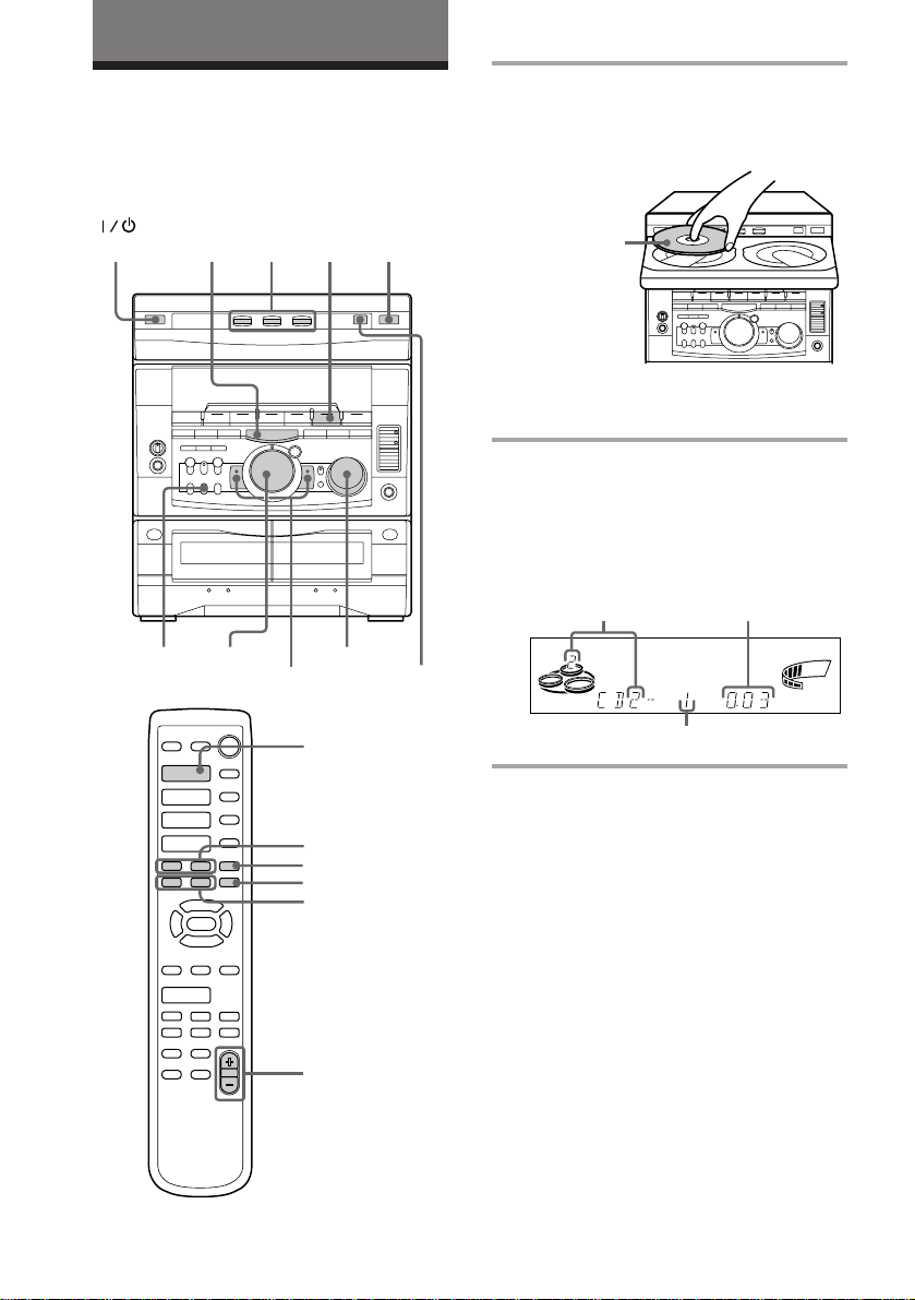
Playing a CD
— Normal play
You can play up to three CDs in a row.
(Power)
MODE
p
= +PLAY
2
0 )
CD
(P
VOLUME
DISC SKIP/
EX-CHANGE
1
1 Press § and place up to two CDs on
the disc tray.
If a disc is not placed properly it will not
be recognized.
With the label
side up. When
you play a single
CD, place it on
the inner circle
of the tray.
To insert a third disc, press DISC SKIP/
EX-CHANGE to rotate the disc tray.
2 Press one of the DISC 1~3 buttons.
The disc tray closes and play starts.
If you press CD (P (or CD · on the
remote) when the disc tray is closed,
play starts from the CD loaded on the
tray whose button is lit green.
Disc tray number
SYNC
ALL1 DISCS PROGRAM
SHUFFLE REPEAT1
Playing time
STEP
VOLUME
ß
12
·
·ª
·ª
=
+
)0P
◊
√
·
=
+
)0P
p
p
CD ·
= +
p
P
0 )
VOLUME +/–
Track number
To Do this
Stop play Press p.
Pause Press CD (P (P on the
remote). Press again to resume
play.
Select a track During play or pause, turn the
jog dial clockwise (to go
forward) or counterclockwise
(to go back) and release it
when you reach the desired
track. (Or press + (to go
forward) or = (to go back)
on the remote.)
Find a point in Press and hold down ) or
a track 0 during play and
release it at the desired point.
Select a CD Press a DISC 1~3 button or
in stop mode DISC SKIP/EX-CHANGE.
Play only the Press PLAY MODE
CD you have repeatedly until “1 DISC”
selected appears.
Play all CDs Press PLAY MODE repeatedly
until “ALL DISCS” appears.
Remove the CD Press §.
Exchange other Press DISC SKIP/
CDs while EX-CHANGE.
playing
Adjust the Turn VOLUME (or press VOL
volume +/– on the remote).
Tips
• Pressing CD (P when the power is off
automatically turns the power on and starts CD
playback if there is a CD in the tray (One Touch
Play).
• You can switch from another source to the CD
player and start playing a CD just by pressing
CD (P or the DISC 1~3 buttons (Automatic
Source Selection).
• If there is no CD in the player, “CD NO DISC”
appears in the display.
• When a disc tray holding a CD is selected (or
playing), the DISC 1~3 button for that tray lights
green. When a disc tray holding a CD is not
selected, the DISC 1~3 button for that tray lights
orange. When all disc trays are empty, the DISC
1~3 buttons all light green.
Basic Operations
13
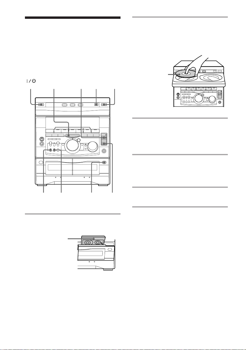
Recording a CD
— CD Synchro Recording
The CD SYNC button lets you record from a
CD to a tape easily. You can use TYPE I
(normal) or TYPE II (CrO2) tapes. The
recording level is adjusted automatically.
DISC SKIP/
(Power)
p
5
EX-CHANGE
2
2 Press § and place a CD.
Then press again to close the disc tray.
If the indicator for the tray you want to
record is not lit green, press DISC SKIP/
EX-CHANGE repeatedly so that it lights
green.
With the label
side up. When
you play a single
CD, place it on
the inner circle
of the tray.
3 Press CD SYNC.
Deck B stands by for recording and the
CD player stands by for playback. The
indicator on TAPE B ( (for front side)
lights up.
4 Press DIRECTION repeatedly to
select A to record on one side.
Select ß (or RELAY) to record on
both sides.
DOLBY NR
4
1 Press § and insert a blank tape into
deck B.
With the side
you want to
record facing
forward
14
1
3
5 Press P PAUSE.
Recording starts.
To stop recording
Press p.
Tips
• If you want to record from the reverse side, press
TAPE B 9 to light its indicator after pressing CD
SYNC.
• When you record on both sides, be sure to start
from the front side. If you start from the reverse
side, recording stops at the end of the reverse side.
• When you want to reduce the hiss noise in lowlevel high-frequency signals, press DOLBY NR so
that “DOLBY NR” appears after pressing CD
SYNC.
Note
You cannot listen to other sources while recording.
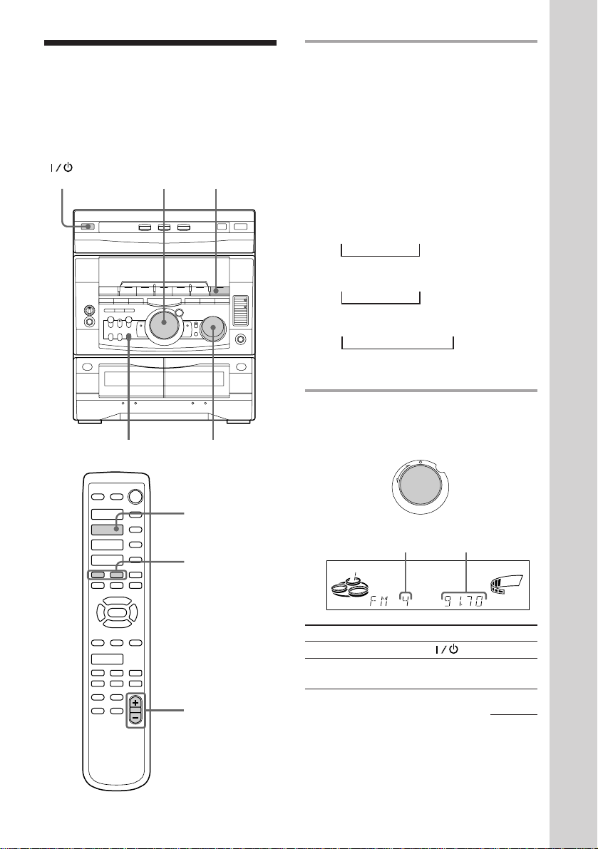
Listening to the radio
–– Preset Tuning
Preset radio stations in the tuner's memory
first (see “Step 3: Presetting radio stations”).
(Power)
·
·ª
·ª
=
+
)0P
◊
√
·
=
+
)0P
2
p
p
1
VOLUMESTEREO/MONO
TUNER/BAND
= +
1 Press TUNER/BAND repeatedly
until the band you want appears in
the display.
The bands you can receive vary
depending on the model you purchased.
Be sure to check which bands you can
receive.
Every time you press the button, the
band changes as follows:
2 band model:
FM ˜ AM
3 band model:
FM n MW n SW
n
or
FM n MW n LW
n
4 band model:
FM n MW n LW n UKV*
n
* “STEREO PLUS” is displayed when
you select UKV.
2 Turn the jog dial (or press = or
+ on the remote) to tune in the
desired preset station.
Turn counterclockwise
(or press =
on the remote)
for lower preset
+
=
numbers.
Preset number Frequency
ALL DISCS
To Do this
Turn off the radio Press .
Adjust the volume Turn VOLUME (or press
VOL +/– on the remote).
Turn clockwise
(or press +
on the remote)
for higher
preset numbers.
VOLUME
kHz
MHz
Basic Operations
ß
VOLUME +/–
continued
15
 Loading...