

Sony DCR-SR210E,DCR-SR220,DCR-SR220D,DCR-SR220E,HDR-SR10,HDR-SR10D,HDR-SR10E Service Manual
SERVICE MANUAL
Sony EMCS Co.
LEVEL 2
Link
SERVICE NOTE
MODEL INFORMATION TABLE
SPECIFICATIONS
FRAME SCHEMATIC DIAGRAM
BLOCK DIAGRAMS
DISASSEMBLY
PRINTED WIRING BOARDS
REPAIR PARTS LIST
SCHEMATIC DIAGRAMS
Link
Revision History
Revision History
DCR-SR210E/SR220/SR220D/SR220E/
HDR-SR10/SR10D/SR10E_L2
DCR-SR210E/SR220/SR220D/SR220E
DIGITAL VIDEO CAMERA RECORDER
The components identified by
mark 0 or dotted line with
mark 0 are critical for safety.
Replace only with part number specified.
Les composants identifiés par une
marque 0 sont critiques pour la
sécurité.
Ne les remplacer que par une pièce
portant le numéro spécifié.
2008A0800-1
© 2008.01
Published by Kohda TEC
9-852-255-31
• Precaution on Replacing the VC-516 Board
•Precaution on Replacing the CABINET (G(700)) ASSY
RMT-835
Ver. 1.0 2008.01
Photo: HDR-SR10
US Model
Canadian Model
AEP Model
UK Model
North European Model
E Model
Australian Model
Hong Kong Model
Chinese Model
Korea Model
Tourist Model
Japanese Model
DCR-SR210E/SR220/SR220D/SR220E/
HDR-SR10/SR10D/SR10E
HDR-SR10/SR10D/SR10E
DIGITAL HD VIDEO CAMERA RECORDER
— 2 —
ENGLISH JAPANESE
ENGLISH JAPANESE
DCR-SR210E/SR220/SR220D/SR220E/
HDR-SR10/SR10D/SR10E_L2
SPECIFICATIONS
These specifications are extracted from instruction manual of
DCR-SR210E/SR220E.
System
Video compression format: MPEG2/JPEG (Still
images)
Audio compression format: Dolby Digital 2/5.1ch
Dolby Digital 5.1 Creator
Video signal: PAL color, CCIR standards
Hard Disk: 60 GB
When measuring media capacity, 1GB
equals 1 billion bytes, a portion of which is
used for data management.
Recording format: Movie: MPEG2-PS
Still image: Exif Ver.2.2 *
Image device: 3.6 mm (1/5 type) CMOS sensor
Recording pixels (still image, 4:3):
Max. 4.0 mega (2 304
×
1 728) pixels**
Gross: Approx. 2 360 000 pixels
Effective (Movie, 16:9)
Approx. 1 490 000 pixels
Effective (Still image, 16:9)
Approx. 1 490 000 pixels
Effective (Still image, 4:3)
Approx. 1 990 000 pixels
Lens:Carl Zeiss Vario-Sonnar T
Optical:15 ×, Digital: 30×, 180
×
Filter diameter: 30 mm (1 3/16 in.)
Focal length: F=1.8 - 2.6
f=3.1 - 46.5 mm (1/8 - 1 7/8 in.)
When converted to a 35 mm still camera
For movies: 40 - 600 mm (1 5/8 - 23 5/8 in.)
(16:9)
For still images: 37 - 555 mm (1 1/2 - 21 7/8
in.) (4:3)
Color temperature: [AUTO], [ONE PUSH],
[INDOOR] (3 200 K), [OUTDOOR] (5800
K)
Minimum illumination: 5 lx (lux) (when [AUTO
SLW SHUTTR] is set to [ON], Shutter speed
1/25 second)
0 lx (lux) (during NightShot function)
*“Exif ” is a file format for still images,
established by the JEITA (Japan Electronics
and Information Technology Industries
Association). Files in this format can
have additional information such as your
camcorder’s setting information at the time of
recording.
**The unique pixel array of
Sony’sClearVid
CMOS Sensor and image processing system
(BIONZ) allows still image resolution
equivalent to the sizes described.
Input/Output connectors
A/V Remote Connector: Video/audio output jack
USB jack: mini-B
(DCR-SR210E: output only)
LCD screen
Picture: 6.7 cm (2.7 type, aspect ratio 16:9)
Total number of pixels: 211 200 (960
×
220)
General
Power requirements: 6.8 V/7.2 V (battery pack)
8.4 V (AC Adaptor)
Average power consumption: Hard disk: 3.5 W
“Memory Stick PRO Duo”: 3.5 W
Operating temperature: 0˚C to + 40˚C (32 ˚F to
104 ˚F)
Storage temperature: -20˚C to + 60˚C (-4 ˚F to
+ 140 ˚F)
Dimensions (Approx.): 81
×
76 × 129 mm (3 1/4
×
3 × 5 1/8 in.)
(w
×h×
d) including the projecting parts
81
×
76 × 134 mm (3 1/4 × 3 × 5 3/8 in.)
(w
×h×
d) including the projecting parts with
supplied battery pack attached
Mass (Approx.): 470 g (1 lb) main unit only
550 g (1 lb 3 oz) including the supplied
rechargeable battery pack
Handycam Station DCRA-C220
Input/Output connector
A/V OUT jack: Video/audio output jack
USB jack: mini-B
(DCR-SR210E: output only)
AC Adaptor AC-L200/L200B
Power requirements: AC 100 V - 240 V, 50/60 Hz
Current consumption: 0.35 – 0.18A
Power consumption: 18 W
Output voltage: DC 8.4 V*
Operating temperature: 0˚C to + 40˚C (32 ˚F to
104 ˚F)
Storage temperature: -20˚C to + 60˚C (-4 ˚F to
+ 140 ˚F)
Dimensions (Approx.): 48
×
29 × 81 mm (1 15/16
×
1 3/16 × 3 1/4 in.)(w×h×d) excluding the
projecting parts
Mass (Approx.): 170 g (6.0 oz) excluding the
power cord (mains lead)
* See the label of AC Adaptor for other
specifications.
Rechargeable battery pack
NP-FH60
Maximum output voltage: DC 8.4 V
Output voltage: DC 7.2 V
Capacity: 7.2 wh (1 000 mAh)
Type: Li-ion
Design and specifications are subject to change
without notice.
— 3 —
ENGLISH JAPANESE
ENGLISH JAPANESE
DCR-SR210E/SR220/SR220D/SR220E/
HDR-SR10/SR10D/SR10E_L2
SPECIFICATIONS
These specifications are extracted from instruction manual of
DCR-SR220/SR220D.
System
Video compression format: MPEG2/JPEG (Still
images)
Audio compression format: Dolby Digital 2/5.1ch
Dolby Digital 5.1 Creator
Video signal: NTSC color, EIA standards
Hard Disk
: 120 GB (DCR-SR220D)
When measuring media capacity, 1GB
equals 1 billion bytes, a portion of which is
used for data management.
Recording format: Movie: MPEG2-PS
Still image: Exif Ver.2.2 *
Image device: 3.6 mm (1/5 type) CMOS sensor
Recording pixels (still image, 4:3):
Max. 4.0 mega (2 304
× 1 728) pixels**
Gross: Approx. 2 360 000 pixels
Effective (Movie, 16:9)
Approx. 1 490 000 pixels
Effective (Still image, 16:9)
Approx. 1 490 000 pixels
Effective (Still image, 4:3)
Approx. 1 990 000 pixels
Lens:Carl Zeiss Vario-Sonnar T
Optical:15 ×, Digital: 30 ×, 180 ×
Filter diameter: 30 mm (1 3/16 in.)
Focal length: F=1.8 - 2.6
f=3.1 - 46.5 mm (1/8 - 1 7/8 in.)
When converted to a 35 mm still camera
For movies: 40 - 600 mm (1 5/8 - 23 5/8 in.)
(16:9)
For still images: 37 - 555 mm (1 1/2 - 21 7/8
in.) (4:3)
Color temperature: [AUTO], [ONE PUSH],
[INDOOR] (3 200 K), [OUTDOOR] (5800
K)
Minimum illumination: 5 lx (lux) (when [AUTO
SLW SHUTTR] is set to [ON], Shutter speed
1/30 second)
0 lx (lux) (during NightShot function)
*“Exif ” is a file format for still images,
established by the JEITA (Japan Electronics
and Information Technology Industries
Association). Files in this format can
have additional information such as your
camcorder’s setting information at the time of
recording.
**The unique pixel array of Sony’sClearVid
CMOS Sensor and image processing system
(BIONZ) allows still image resolution
equivalent to the sizes described.
Input/Output connectors
A/V Remote Connector: Video/audio output jack
USB jack: mini-B
LCD screen
Picture: 6.7 cm (2.7 type, aspect ratio 16:9)
Total number of pixels: 211 200 (960
× 220)
General
Power requirements: 6.8 V/7.2 V (battery pack)
8.4 V (AC Adaptor)
Average power consumption: Hard disk: 3.6 W
“Memory Stick PRO Duo”: 3.5 W
Operating temperature: 0˚C to + 40˚C (32 ˚F to
104 ˚F)
Storage temperature: -20˚C to + 60˚C (-4 ˚F to
+ 140 ˚F)
Dimensions (Approx.): 81
× 76 × 129 mm (3 1/4
× 3 × 5 1/8 in.)
(w
×h×d) including the projecting parts
81
× 76 × 134 mm (3 1/4 × 3 × 5 3/8 in.)
(w
×h×d) including the projecting parts with
supplied battery pack attached
Mass (Approx.): 470 g (1 lb) main unit only
550 g (1 lb 3 oz) including the supplied
rechargeable battery pack (DCR-SR220)
: 480 g (1 lb) main unit only
560 g (1 lb 3 oz) including the supplied
rechargeable battery pack (DCR-SR220D)
Handycam Station DCRA-C220
Input/Output connector
A/V OUT jack: Video/audio output jack
USB jack: mini-B
AC Adaptor AC-L200/L200B
Power requirements: AC 100 V - 240 V, 50/60 Hz
Current consumption: 0.35 – 0.18A
Power consumption: 18 W
Output voltage: DC 8.4 V*
Operating temperature: 0˚C to + 40˚C (32 ˚F to
104 ˚F)
Storage temperature: -20˚C to + 60˚C (-4 ˚F to
+ 140 ˚F)
Dimensions (Approx.): 48
× 29 × 81 mm (1 15/16
× 1 3/16 × 3 1/4 in.) (w×h×d) excluding the
projecting parts
Mass (Approx.): 170 g (6.0 oz) excluding the
power cord (mains lead)
*
specifications.
Rechargeable battery pack
NP-FH60
Maximum output voltage: DC 8.4 V
Output voltage: DC 7.2 V
Capacity: 7.2 wh (1 000 mAh)
Type: Li-ion
Design and specifications are subject to change
without notice.
See the label of AC Adaptor for other
: 60 GB (DCR-SR220)

— 4 —
ENGLISH JAPANESE
ENGLISH JAPANESE
DCR-SR210E/SR220/SR220D/SR220E/
HDR-SR10/SR10D/SR10E_L2
SPECIFICATIONS
These specifications are extracted from instruction manual of
HDR-SR10E.
System
Video compression format: AVCHD (HD)/
MPEG2/JPEG (Still images)
Audio compression format: Dolby Digital 2/5.1ch
Dolby Digital 5.1 Creator
Video signal: PAL color, CCIR standards
1080/50i specification
Hard disk: 40 GB
When measuring media capacity, 1 GB equals
1billion bytes, a portion of which is used for
data management.
Recording format: Movie (HD): AVCHD 1080/
50i
Movie (SD): MPEG2-PS
Still image: Exif Ver.2.2*
Image device: 3.6 mm (1/5 type) CMOS sensor
Recording pixels (still image, 4:3):
Max. 4.0 mega (2 304 × 1728) pixels**
Gross: Approx. 2 360 000 pixels
Effective (movie, 16:9):
Approx. 1 490 000 pixels
Effective (still image, 16:9):
Approx. 1 490 000 pixels
Effective (still image, 4:3):
Approx. 1 990 000 pixels
Lens: Carl Zeiss Vario-Sonnar T
15 × (Optical), 30 ×, 180 × (Digital)
Focal length: F1.8 ~ 2.6
Filter diameter: 30 mm (1 3/16 in.)
f=3.1 ~ 46.5 mm (1/8 ~ 1 7/8 in.)
When converted to a 35 mm still camera
For movies: 40 ~ 600 mm (1 5/8 ~ 235/8 in.)
(16:9)
For still images: 37 ~ 555 mm (1 1/2 ~ 21 7/8
in.) (4:3)
Color temperature: [AUTO], [ONE PUSH],
[INDOOR] (3 200 K),
[OUTDOOR] (5 800 K)
Minimum illumination: 5 lx (lux) ([AUTO SLW
SHUTTR] [ON], Shutter speed 1/25 sec)
0 lx (lux) (during NightShot function)
AC Adaptor AC-L200/L200B
Power requirements: AC 100 V - 240 V, 50/60 Hz
Current consumption: 0.35 - 0.18 A
* “Exif” is a file format for still images,
established by the JEITA (Japan
Electronics and Information Technology
Industries Association). Files in this
format can have additional information
such as your camcorder’s setting
information at the time of recording.
**The unique pixel array of Sony’s ClearVid
CMOS sensor and image processing
system (BIONZ) allows for still image
resolution equivalent to the sizes
described.
Input/Output connectors
A/V Remote Connector: Component/video and
audio output jack
HDMI OUT jack: HDMI Type C mini connector
USB jack: mini-B
LCD screen
Image: 6.7 cm (2.7 type, aspect ratio 16:9)
Total dot number: 211 200 (960 × 220)
General
Power requirements: DC 6.8 V/7.2 V (battery
pack)
DC 8.4 V (AC Adaptor)
Average power consumption: During camera
recording with normal brightness:
Hard disk:
HD: 4.2 W SD: 3.6 W
“Memory Stick PRO Duo”:
HD: 4.2 W SD: 3.6 W
Operating temperature: 0 ˚C to + 40 ˚C (32 ˚F to
104 ˚F)
Storage temperature: -20 ˚C to + 60 ˚C (-4 ˚F to +
140 ˚F)
Dimensions (approx.): 81 × 76 × 129 mm
(3 1/4 × 3 × 5 1/8 in.) (w/h/d)
including the projecting parts
81 × 76 × 134 mm
(3 1/4 × 3 × 53/8 in.) (w/h/d)
including the projecting parts, and the supplied
rechargeable battery pack attached
Mass (approx.): 480 g (1 lb) main unit only
560 g (1 lb 3 oz) including the supplied
rechargeable battery pack
Handycam Station DCRA-C220
Input/Output connectors
A/V OUT jack: Component/video and audio
output jack
USB jack: mini-B
Power consumption: 18 W
Output voltage: DC 8.4 V*
Operating temperature: 0 ˚C to + 40 ˚C (32 ˚F to
104 ˚F)
Storage temperature: -20 ˚C to + 60 ˚C (-4 ˚F to +
140 ˚F)
Dimensions (approx.): 48 × 29 × 81 mm
(1 15/16 × 1 3/16 × 31/4 in.) (w/h/d)
excluding the projecting parts
Mass (approx.): 170 g (6.0 oz) excluding the
power cord (mains lead)
* See the label on the AC Adaptor for other
specifications.
Rechargeable battery pack NP-FH60
Maximum output voltage: DC 8.4 V
Output voltage: DC 7.2 V
Capacity: 7.2 Wh (1 000 mAh)
Type: Li-ion
Design and specifications of your camcorder and
accessories are subject to change without notice.
— 5 —
ENGLISH JAPANESE
ENGLISH JAPANESE
DCR-SR210E/SR220/SR220D/SR220E/
HDR-SR10/SR10D/SR10E_L2
SPECIFICATIONS
These specifications are extracted from instruction manual of
HDR-SR10/SR10D.
System
Video compression format: AVCHD (HD)/
MPEG2/JPEG (Still images)
Audio compression format: Dolby Digital 2/5.1ch
Dolby Digital 5.1 Creator
Video signal: NTSC color, EIA standards
1080/60i specification
Hard disk: 40 GB (HDR-SR10)
: 120 GB (HDR-SR10D)
When measuring media capacity, 1 GB equals
1billion bytes, a portion of which is used for
data management.
Recording format: Movie (HD): AVCHD 1080/
60i
Movie (SD): MPEG2-PS
Still image: Exif Ver.2.2*
Image device: 3.6 mm (1/5 type) CMOS sensor
Recording pixels (still image, 4:3):
Max. 4.0 mega (2 304 × 1 728) pixel s**
Gross: Approx. 2 360 000 pixels
Effective (movie, 16:9):
Approx. 1 490 000 pixels
Effective (still image, 16:9):
Approx. 1 490 000 pixels
Effective (still image, 4:3):
Approx. 1 990 000 pixels
Lens: Carl Zeiss Vario-Sonnar T
15 × (Optical), 30 ×, 180 × (Digital)
Focal length: F1.8 ~ 2.6
Filter diameter: 30 mm (1 3/16 in.)
f=3.1 ~ 46.5 mm (1/8 ~ 1 7/8 in.)
When converted to a 35 mm still camera
For movies: 40 ~ 600 mm (1 5/8 ~ 23 5/8 in.)
(16:9)
For still images: 37 ~ 555 mm (1 1/2 ~ 21 7/8
in.) (4:3)
Color temperature: [AUTO], [ONE PUSH],
[INDOOR] (3 200 K),
[OUTDOOR] (5 800 K)
Minimum illumination: 5 lx (lux) ([AUTO SLW
SHUTTR] [ON], Shutter speed 1/30 sec)
0 lx (lux) (during NightShot function)
Input/Output connectors
A/V Remote Connector: Component/video and
audio output jack
HDMI OUT jack: HDMI Type C mini connector
USB jack: mini-B
LCD screen
Image: 6.7 cm (2.7 type, aspect ratio 16:9)
Total dot number: 211 200 (960 × 220)
General
Power requirements: DC 6.8 V/7.2 V (battery
pack)
DC 8.4 V (AC Adaptor)
Average power consumption: During camera
recording with normal brightness:
Hard disk:
HD: 4.5 W SD: 3.7 W
“Memory Stick PRO Duo”:
HD: 4.5 W SD: 3.7 W
Operating temperature: 0 ˚C to + 40 ˚C (32 ˚F to
104 ˚F)
Storage temperature: -20 ˚C to + 60 ˚C (-4 ˚F to +
140 ˚F)
Dimensions (approx.): 81 × 76 × 129 mm
(3 1/4 × 3 × 5 1/8 in.) (w/h/d)
including the projecting parts
81 × 76 × 134 mm
(3 1/4 × 3 × 53/8 in.) (w/h/d)
including the projecting parts, and the supplied
rechargeable battery pack attached
Mass (approx.): 480 g (1 lb) main unit only
560 g (1 lb 3 oz) including the supplied
rechargeable battery pack (HDR-SR10)
: 490 g (1 lb) main unit only
570 g (1 lb 3 oz) including the supplied
rechargeable battery pack (HDR-SR10D)
Handycam Station DCRA-C220
Input/Output connectors
A/V OUT jack: Component/video and
audio
output jack
USB jack: mini-B
AC Adaptor AC-L200/L200B
Power requirements: AC 100 V - 240 V, 50/60 Hz
Current consumption: 0.35 - 0.18 A
* “Exif” is a file format for still images,
established by the JEITA (Japan
Electronics and Information Technology
Industries Association). Files in this
format can have additional information
such as your camcorder’s setting
information at the time of recording.
**The unique pixel array of Sony’s ClearVid
CMOS sensor and image processing
system (BIONZ) allows for still image
resolution equivalent to the sizes
described.
Power consumption: 18 W
Output voltage: DC 8.4 V*
Operating temperature: 0 ˚C to + 40 ˚C (32 ˚F to
104 ˚F)
Storage temperature: -20 ˚C to + 60 ˚C (-4 ˚F to +
140 ˚F)
Dimensions (approx.): 48 × 29 × 81 mm
(1 15/16 × 1 3/16 × 3 1/4 in.) (w/h/d)
excluding the projecting parts
Mass (approx.): 170 g (6.0 oz) excluding the
power cord (mains lead)
* See the label on the AC Adaptor for other
specifications.
Rechargeable battery pack NP-FH60
Maximum output voltage: DC 8.4 V
Output voltage: DC 7.2 V
Capacity: 7.2 Wh (1 000 mAh)
Type: Li-ion
Design and specifications of your camcorder and
accessories are subject to change without notice.
— 6 —
ENGLISH JAPANESE
ENGLISH JAPANESE
DCR-SR210E/SR220/SR220D/SR220E/
HDR-SR10/SR10D/SR10E_L2
概略仕様
システム
映像圧縮方式:
MPEG2 /JPEG
(静止画)
音声圧縮方式:
Dolby Digital2/5.1ch
ドルビーデジタル
5.1
クリエーター搭載
映像信号:
NTSC
カラー、
EIA
標準方式
ハードディスク:
60 GB
容量は、
1GBを10
億バイトで計算した場合の数
値です。また管理用ファイルなどを含むため、実
際使用できる容量は若干減少する場合がありま
す。
動画記録方式
:
MPEG2-PS
静止画記録方式:
Exif Ver.2.2*
1
撮像素子:
3.6 mm(1/5型)CMOS
センサー
記録画素数:静止画時最大
400
万画素相当
*
2
(
2 304×1 728)(4:3
時)
総画素数:約
236
万画素
動画時有効画素数(
16:9
):約
149
万画素
静止画時有効画素数(
16:9
):約
149
万画素
静止画時有効画素数(
4:3
):約
199
万画素
ズームレンズ:カ ール ツァイス バリオゾナー
T
15
倍(光学)、30倍、
180
倍(デジタル)
フィルター径
30 mm
F1.8
〜
2.6
f=3.1
〜
46.5 mm
35mm
カメラ換算では
40〜600 mm(16:9
)
静止画撮影時:
37〜555 mm(4:3
)
色温度切り換え:[オート]、[ワンプッシュ]、[屋内]
(
3 200 K
)、[屋外](
5 800 K
)
最低被写体照度:
5 lx
(ルクス)([オートスロシャッ
タ][入]、[シャッタースピード]
1/30
秒)
0 lx
(ルクス)(
NightShot
時)
*
1
(社)電子情報技術産業協会(
JEITA
)にて制定
された、撮影情報などの付帯情報を追加する
ことができる静止画用のファイルフォーマッ
ト。
*
2
ソニー独自のクリアビッド
CMOS
センサー
の画素配列と画像処理システム
BIONZ
によ
り、静止画は表記の記録サイズを実現してい
ます。
入/出力端子
A/V
リモート端子:映像音声出力端子
USB
端子:
mini-B
A/V
OUT
端子:映像音声出力端子
USB
端子:
mini-B
液晶画面
画面サイズ:
6.7 cm(2.7
型、アスペクト比16:9)
総ドット数:
211 200
ドット
横
960×縦220
電源部、その他
電源電圧:バッテリー端子入力
6.8 V/7.2 V
DC
端子入力
8.4 V
消費電力:
ハードディスク:
3.6
W
3.5
W
メモリースティック
PRO
デュオ :
動作温度:
0℃〜+40
℃
保存温度:−
20℃〜+60
℃
外形寸法:
81×76×129 mm
(突起部を含む)
(幅×高さ×奥行き)
81×76×134 mm
(突起部を含む、付属バッテリー装着状態)
(幅×高さ×奥行き)
本体質量:約
470 g
(本体のみ)
撮影時総質量: 約
550 g
(付属バッテリー含む。
ハンディカムステーション
DCRA-C220
入/出力端子
AC
アダプター
AC-L200/L200B
電源:
AC 100 V - 240 V、50/60 Hz
消費電力:
18 W
定格出力:
DC 8.4 V *
動作温度:0℃〜
+40
℃
保存温度:−
20℃〜+60
℃
外形寸法:約
48×29×81 mm
(最大突起部をのぞ
く)(幅×高さ×奥行き)
質量:約
170 g
(本体のみ)
* その他の仕様については
AC
アダプターのラベル
をご覧ください。
リチャージャブルバッテリーパック
NP-FH60
最大電圧:
DC 8.4 V
公称電圧:
DC 7.2 V
容量:
7.2 Wh(1 000 mAh
)
使用電池:
Li-ion
本機やアクセサリーの仕様および外観は、改良のた
め予告なく変更することがありますが、ご了承くだ
さい。
動画撮影時
:
)

— 7 —
DCR-SR210E/SR220/SR220D/SR220E/
HDR-SR10/SR10D/SR10E_L2
Model information table
•Abbreviation
AUS: Australian model
CH : Chinese model
CND: Canadian model
HK : Hong Kong model
J: Japanese model
JE : Tourist model
KR : Korea model
NE : North European model
HDR-SR10E
AEP, UK, NE, E,
CH, HK, AUS, JE
PAL
HDR-SR10
US, CND, E, KR, JE
NTSC
Model
Destination
FP-855 Flexible
Board
Video compression
format
AVCHD (HD)/
MPEG2/JPEG (Still image)
AVCHD (HD)/
MPEG2/JPEG (Still image)
AVCHD (HD)/
MPEG2/JPEG (Still image)
Color system
40GB 40GBHard disk
HDMI OUT jack
HDR-SR10D
US
NTSC
120GB
DCR-SR220D
NTSC
DCR-SR210E
AEP, UK
PAL
Model
Destination
FP-855 Flexible
Board
Color system
60GB 120GBHard disk
HDMI OUT jack
DCR-SR220
US, CND, E, KR, JE, J US
NTSC
60GB
DCR-SR220E
NE, E, CH, HK,
AUS, JE
PAL
60GB
CAM PC
PC CAM
Data
copy
Video compression
format
MPEG2/JPEG (Still image) MPEG2/JPEG (Still image) MPEG2/JPEG (Still image)
CAM PC
MPEG2/JPEG (Still image)
PC CAM
Data
copy
— 8 —
ENGLISH JAPANESE
ENGLISH JAPANESE
DCR-SR210E/SR220/SR220D/SR220E/
HDR-SR10/SR10D/SR10E_L2
SAFETY-RELATED COMPONENT WARNING!!
COMPONENTS IDENTIFIED BY MARK 0 OR DO TTED LINE WITH
MARK 0 ON THE SCHEMATIC DIAGRAMS AND IN THE PARTS
LIST ARE CRITICAL TO SAFE OPERATION. REPLACE THESE
COMPONENTS WITH SONY PARTS WHOSE PART NUMBERS
APPEAR AS SHOWN IN THIS MANUAL OR IN SUPPLEMENTS
PUBLISHED BY SONY .
1. Check the area of your repair for unsoldered or poorly-soldered
connections. Check the entire board surface for solder splashes
and bridges.
2. Check the interboard wiring to ensure that no wires are
"pinched" or contact high-wattage resistors.
3. Look for unauthorized replacement parts, particularly
transistors, that were installed during a previous repair. Point
them out to the customer and recommend their replacement.
4. Look for parts which, through functioning, show obvious signs
of deterioration. Point them out to the customer and
recommend their replacement.
5. Check the B+ voltage to see it is at the values specified.
6. Flexible Circuit Board Repairing
•Keep the temperature of the soldering iron around 270˚C
during repairing.
• Do not touch the soldering iron on the same conductor of the
circuit board (within 3 times).
• Be careful not to apply force on the conductor when soldering
or unsoldering.
SAFETY CHECK-OUT
After correcting the original service problem, perform the following
safety checks before releasing the set to the customer.
ATTENTION AU COMPOSANT AYANT RAPPORT
À LA SÉCURITÉ!
LES COMPOSANTS IDENTIFÉS PAR UNE MARQUE 0 SUR LES
DIAGRAMMES SCHÉMATIQUES ET LA LISTE DES PIÈCES SONT
CRITIQUES POUR LA SÉCURITÉ DE FONCTIONNEMENT. NE
REMPLACER CES COMPOSANTS QUE PAR DES PIÈSES SONY
DONT LES NUMÉROS SONT DONNÉS DANS CE MANUEL OU
DANS LES SUPPÉMENTS PUBLIÉS PAR SONY.
Unleaded solder
Boards requiring use of unleaded solder are printed with the leadfree mark (LF) indicating the solder contains no lead.
(Caution: Some printed circuit boards may not come printed with
the lead free mark due to their particular size.)
: LEAD FREE MARK
Unleaded solder has the following characteristics.
• Unleaded solder melts at a temperature about 40°C higher than
ordinary solder.
Ordinary soldering irons can be used but the iron tip has to be
applied to the solder joint for a slightly longer time.
Soldering irons using a temperature regulator should be set to
about 350°C.
Caution: The printed pattern (copper foil) may peel away if the
heated tip is applied for too long, so be careful!
• Strong viscosity
Unleaded solder is more viscous (sticky, less prone to flow) than
ordinary solder so use caution not to let solder bridges occur such
as on IC pins, etc.
•Usable with ordinary solder
It is best to use only unleaded solder but unleaded solder may
also be added to ordinary solder.
CAUTION
Danger of explosion if battery is incorrectly replaced.
Replace only with the same or equivalent type.

— 9 —
ENGLISH JAPANESE
ENGLISH JAPANESE
DCR-SR210E/SR220/SR220D/SR220E/
HDR-SR10/SR10D/SR10E_L2
1. 注意事項をお守りください。
サービスのとき特に注意を要する個所については,
キャビネット,シャーシ,部品などにラベルや捺印で
注意事項を表示しています。これらの注意書き及び取
扱説明書等の注意事項を必ずお守り下さい。
2. 指定部品のご使用を
セットの部品は難燃性や耐電圧など安全上の特性を
持ったものとなっています。従って交換部品は,使用
されていたものと同じ特性の部品を使用して下さい。
特に回路図,部品表に0印で指定されている安全上重要
な部品は必ず指定のものをご使用下さい。
3. 部品の取付けや配線の引きまわしはもとどおりに
安全上,チューブやテープなどの絶縁材料を使用した
り,プリント基板から浮かして取付けた部品がありま
す。また内部配線は引きまわしやクランパによって発
熱部品や高圧部品に接近しないよう配慮されています
ので,これらは必ずもとどおりにして下さい。
4. サービス後は安全点検を
サービスのために取外したネジ,部品,配線がもとど
おりになっているか,またサービスした個所の周辺を
劣化させてしまったところがないかなどを点検し,安
全性が確保されていることを確認して下さい。
5. チップ部品交換時の注意
• 取外した部品は再使用しないで下さい。
• タンタルコンデンサのマイナス側は熱に弱いため交
換時は注意して下さい。
サービス,点検時には次のことにご注意下さい。
注意
電池の交換は,正しく行わないと破裂する恐れがあり
ます。電池を交換する場合には必ず同じ型名の電池
又は同等品と交換してください。
6. フレキシブルプリント基板の取扱いについて
• コテ先温度を270℃前後にして行なって下さい。
• 同一パターンに何度もコテ先を当てないで下さい。
(3回以内)
• パターンに力が加わらないよう注意して下さい。
7. 無鉛半田について
無鉛半田を使用している基板には,無鉛(LeadFree)を
意味するレッドフリーマークがプリントされています。
(注意:基板サイズによっては,無鉛半田を使用して
いてもレッドフリーマークがプリントされて
いないものがあります)
:レッドフリーマーク
無鉛半田には,以下の特性があります。
• 融点が従来の半田よりも約40℃高い。
従来の半田こてをそのまま使用することは可能です
が,少し長めにこてを当てる必要があります。
温度調節機能のついた半田こてを使用する場合,約
350℃に設定して下さい。
注意: 半田こてを長く当てすぎると,基板のパター
ン(銅箔)がはがれてしまうことがあります
ので,注意して下さい。
• 粘性が強い
従来の半田よりも粘性が強いため,IC端子などが半田
ブリッジしないように注意して下さい。
• 従来の半田と混ぜて使用可能
無鉛半田には無鉛半田を追加するのが最適ですが,
従来の半田を追加しても構いません。

1-1
ENGLISH JAPANESE
ENGLISH JAPANESE
DCR-SR210E/SR220/SR220D/SR220E/
HDR-SR10/SR10D/SR10E_L2
1. SERVICE NOTE
1-1. POWER SUPPLY DURING REPAIRS
In this unit, about 10 seconds after power is supplied to the battery terminal using the regulated po wer supply (8.4V), the power is shut off so
that the unit cannot operate.
These following method is available to prevent this.
Method:
Use the AC power adaptor (AC-L200/L200B).
1-2. SELF-DIAGNOSIS FUNCTION
1-2-1. Self-diagnosis Function
When problems occur while the unit is operating, the self-diagnosis
function starts working, and displays on the LCD screen what to
do. This function consists of two display; self-diagnosis display and
service mode display.
Details of the self-diagnosis functions are provided in the Instruction
manual.
1-2-2. Self-diagnosis Display
When problems occur while the unit is operating, the counter of the
LCD screen shows a 4-digit display consisting of an alphabet and
numbers, which blinks at 3.2 Hz. This 5-character display indicates
the “repaired by:”, “block” in which the problem occurred, and
“detailed code” of the problem.
1 1
3 1C
Repaired by:
Refer to “1-2-3. Self-diagnosis Code Table”.
Indicates the appropriate
step to be taken.
E.g.
31 ....Reload the tape.
32 ....Turn on power again.
Block
Detailed Code
Blinks at 3.2Hz
C : Corrected by customer
H : Corrected by dealer
E : Corrected by service
engineer
LCD screen
C : 3 1 : 1 1
1-2
ENGLISH JAPANESE
ENGLISH JAPANESE
DCR-SR210E/SR220/SR220D/SR220E/
HDR-SR10/SR10D/SR10E_L2
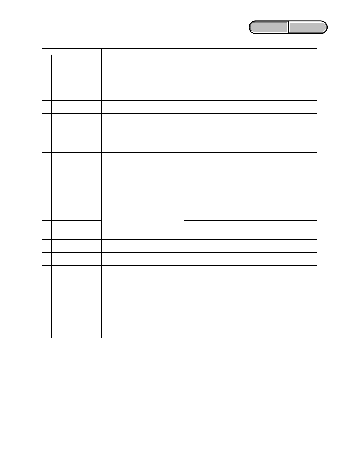
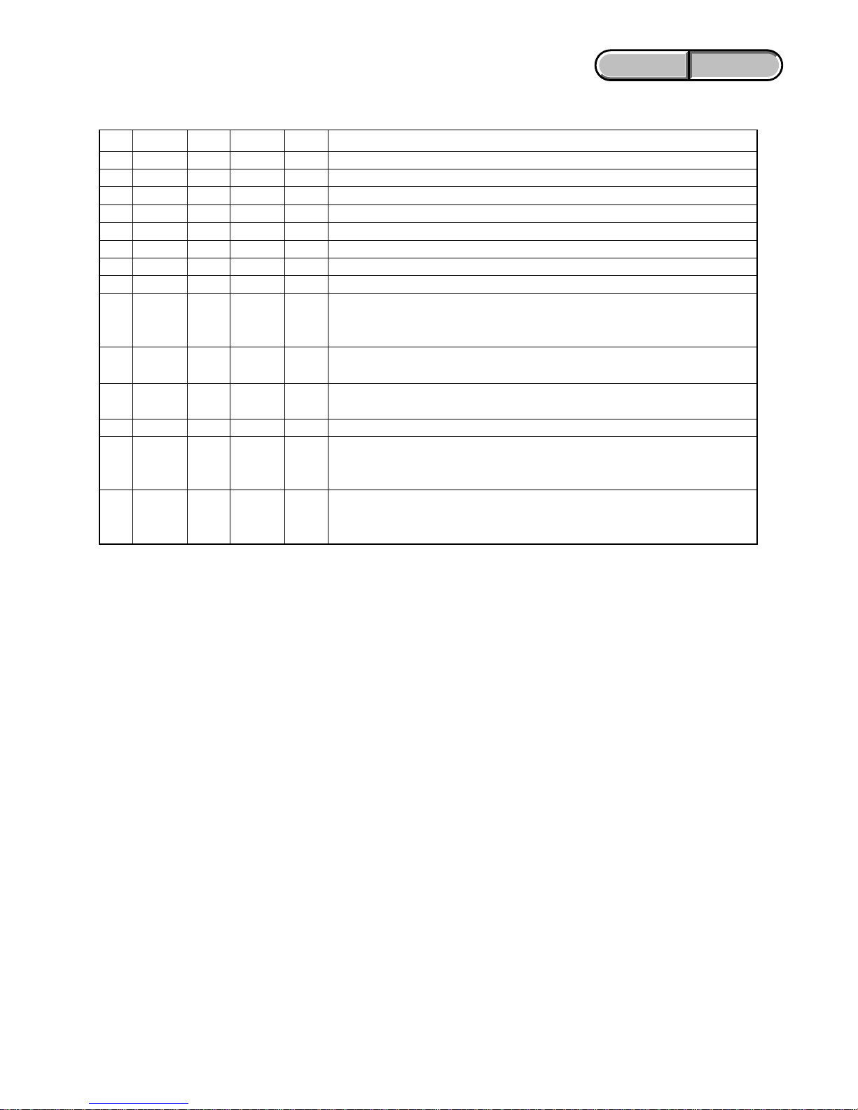
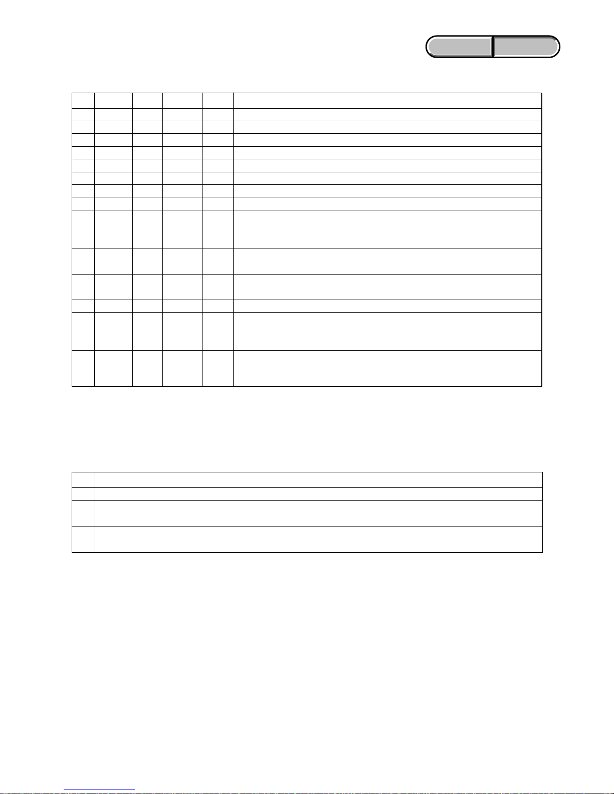
1-2-3. Self-diagnosis Code Tab le
C
C
C
C
E
E
E
E
E
E
E
E
E
E
E
E
E
E
Block
Function
04
13
13
32
20
31
61
61
62
62
62
62
62
62
62
62
91
94
Detailed
Code
00
01
02
60
00
00
10
11
00
01
02
03
10
11
12
20
01
00
Symptom/State
Non-standard battery is used.
“Memory Stick Duo” is unformatted.
“Memory Stick Duo” is broken.
Disc access error
Difficult to adjust focus
(Cannot initialize focus)
Flash memory data are rewritten.
Drive fault
Zoom operations fault
(Cannot initialize zoom lens.)
The abnormalities in initialization of
the focus lens and the abnormalities in
initialization of the zoom lens occurred
simultaneously.
Handshake correction function does not
work well. (With PITCH angular
velocity sensor output stopped.)
Handshake correction function does not
work well. (With YAW angular velocity
sensor output stopped.)
Abnormality of IC for steadyshot.
IC for steadyshot and micro controller
communication abnormality among.
Shift lens initializing failure.
Shift lens overheating (Pitch)
Shift lens overheating (Yaw)
Abnormality of thermistor.
Abnormality when flash is being charged.
Fault of writing or erasing the
flash memory
Self-diagnosis Code
Repaired by:
Correction
Use the InfoLITHIUM battery.
Format the “Memory Stick Duo”.
Insert a new “Memory Stick Duo”.
Remove the power source. Reconnect it again and operate your
camcorder again
Retry turn the power on by the power switch. If it does not
recover, check the focus MR sensor of lens block (pin eg, eh of
CN5101 on the LD-230 board). If it is OK, check the focus
motor drive IC (IC5201 on the LD-230 board).
Make flash memory data correct value. (Note 1)
Inspect or replacement of the hard disk drive.
Inspect the lens block zoom MR sensor (pin ea, ed of CN5101
on the LD-230 board) when zooming is performed when the
zoom lever is operated, and the zoom motor drive circuit
(IC5201 on the LD-230 board) when zooming is not performed.
Check both C: 32: 60 and E: 61: 10 of the self-diagnosis code.
Inspect PITCH angular velocity sensors (SE9501 on the FR-285
board) peripheral circuits.
Inspect YAW angular velocity sensors (SE9502 on the FR-285
board) peripheral circuits.
Refer to [1-3-1. E : 62 : 02 (Abnormality of IC for Steadyshot)
Occurred].
Inspect the steadyshot circuit (IC5501 on the LD-230 board).
Replacement of lens block. If an error occurs again, replace the
LD-230 board. (Note 2)
Refer to [1-3-2. E : 62 : 11 (Shift Lens Overheating (Pitch))
Occurred].
Refer to [1-3-3. E : 62 : 12 (Shift Lens Overheating (Yaw))
Occurred].
Refer to [1-3-4. E : 62 : 20 (Abnormality of Thermistor)
Occurred].
Checking of flash unit or replacement of flash unit.
Inspect the flash memory (IC2101 on the VC-516 board).
Note 1 :Refer to Service Maual, ADJ (“1-3. DESTINATION DATA WRITE”).
Note 2 : When the lens block was replaced, execute the necessary adjustment items referring to Service Manual, ADJ.
After the adjustment, make sure with the STEADYSHOT turned ON that the steadyshot functions appropriately in the
handheld operation.
1-3
ENGLISH JAPANESE
ENGLISH JAPANESE
DCR-SR210E/SR220/SR220D/SR220E/
HDR-SR10/SR10D/SR10E_L2
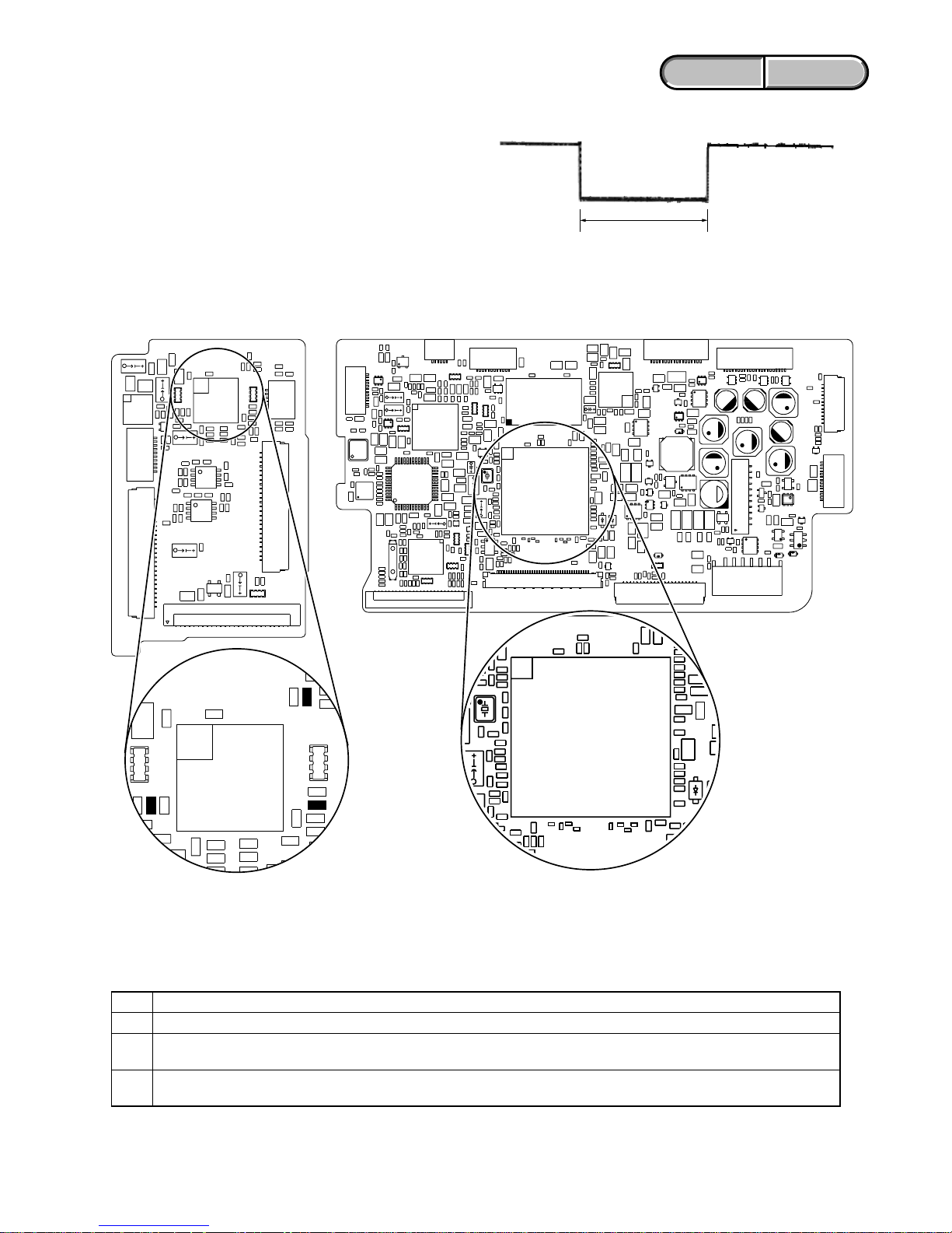
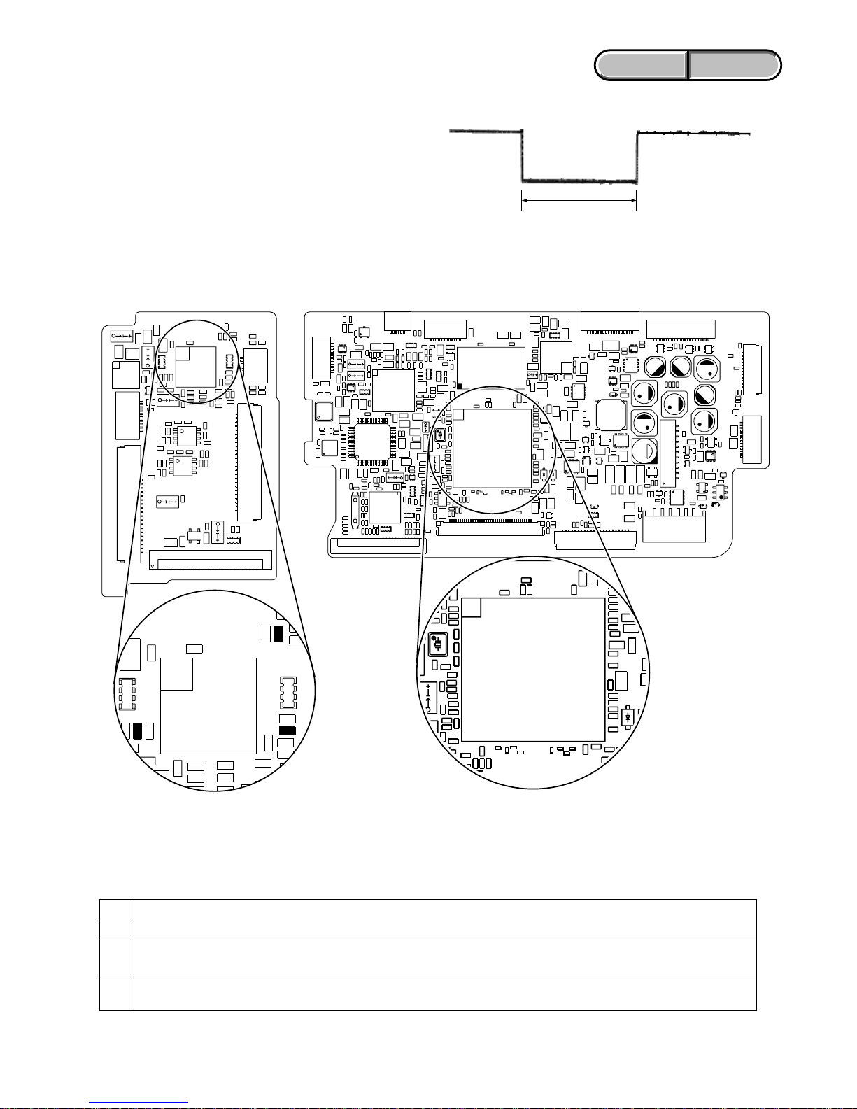
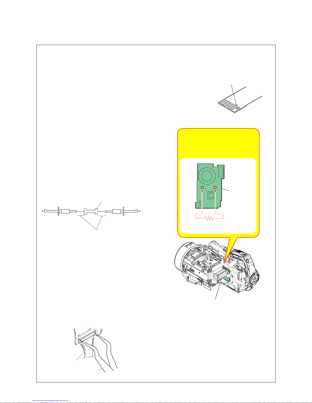
1-3. METHOD OF COPING WITH SHIFT LENS ERROR
about 330 msec
Fig. 2
Change in output voltage of R5549 on the LD-230 board
Note: The length of low section will vary a little depending on the
conditions.
1-3-1. E : 62 : 02 [Abnormality of IC for Steadyshot] Occurred
Order Procedure
1Turn the power OFF.
2
While measuring with an oscilloscope the output voltage of R5549 in the periphery of IC5501 on the LD-230 board, turn the
power ON to check that the output voltage immediately after the power on change as shown in Fig. 2.
3
If the output voltage change as shown in Fig. 2, replace the lens block (Note). If it does not change as shown in Fig. 2, inspect
the camera control circuit (IC1301 of VC-516 board) periphery.
Note: When the lens block was replaced, execute a necessary adjustment items referring to Service Manual, ADJ.
After the adjustment, make sure with the STEADYSHOT turned ON that the steadyshot functions appropriately in the
handheld operation.
VC-516 BOARD (SIDE A)LD-230 BOARD (SIDE A)
IC5501
R5534
R5549
R5526
C5513
4
R5525
R5538
R5549: No Mount
(Short Land)
IC1301
Fig. 1
Measurement points on the LD-230 board and the VC-516 board
1-4
ENGLISH JAPANESE
ENGLISH JAPANESE
DCR-SR210E/SR220/SR220D/SR220E/
HDR-SR10/SR10D/SR10E_L2
1-3-2. E : 62 : 11 [Shift Lens Overheating (Pitch)] Occurred
Connect by the SeusEX and perform the following process.
Order Block Page Address Data Procedure
111807430 01 Write the data. (After it starts, set it before caution is displayed.)
2118EF946 F0 Write the data.
3118EF948 01 Write the data. (Note 1)
4118EF948 00 Write the data.
5118EF946 10 Write the data.
6118EF948 01 Write the data. (Note 1)
7118EF948 00 Write the data.
811807430 00 Write the data.
9
Check if the shift lens moves while setting the order 2 to 7. If the shift lens does not move,
replace the lens block (Note 2). When the shift lens moved, proceed to the order 10.
10
While setting the order 2 to 7, measure with an oscilloscope the output voltage of R5526 in the
periphery of IC5501 on the LD-230 board to check the output voltage varies.
11
If the output voltage does not vary, replace the lens block (Note 2). When the output voltage
varied, proceed to the order 12.
12 Turn the power OFF.
While measuring with an oscilloscope the output voltage of R5549 in the periphery of IC5501
13 on the LD-230 board, turn the power ON to check that the output voltage immediately after the
power on change as shown in Fig. 2.
If the output voltage change as shown in Fig. 2, replace the lens block (Note 2). If it does not
14 change as shown in Fig. 2, inspect the camera control circuit (IC1301 of VC-516 board) pe
riphery.
Note 1: Finish this operation within 10 seconds. If it is likely to take more than 10 seconds, set block: 11, page: 8E, address:
F948, data: 00, and then retry.
Note 2: When the lens block was replaced, execute the necessary adjustment items referring to Service Manual, ADJ.
After the adjustment, make sure with the STEADYSHOT turned ON that the steadyshot functions appropriately in the
handheld operation.
1-5
ENGLISH JAPANESE
ENGLISH JAPANESE
DCR-SR210E/SR220/SR220D/SR220E/
HDR-SR10/SR10D/SR10E_L2
1-3-3. E : 62 : 12 [Shift Lens Overheating (Yaw)] Occurred
Connect by the SeusEX and perform the following process.
Order Block Page Address Data Procedure
111807430 01 Write the data. (After it starts, set it before caution is displayed.)
2118EF947 F0 Write the data.
3118EF949 01 Write the data. (Note 1)
4118EF949 00 Write the data.
5118EF947 10 Write the data.
6118EF949 01 Write the data. (Note 1)
7118EF949 00 Write the data.
811807430 00 Write the data.
9
Check if the shift lens moves while setting the order 2 to 7. If the shift lens does not move,
replace the lens block (Note 2). When the shift lens moved, proceed to the order 10.
10
While setting the order 2 to 7, measure with an oscilloscope the output voltage of R5534 in the
periphery of IC5501 on the LD-230 board to check the output voltage varies.
11
If the output voltage does not vary, replace the lens block (Note 2). When the output voltage
varied, proceed to the order 12.
12 Turn the power OFF.
While measuring with an oscilloscope the output voltage of R5549 in the periphery of IC5501
13 on the LD-230 board, turn the power ON to check that the output voltage immediately after the
power on change as shown in Fig. 2.
If the output voltage change as shown in Fig. 2, replace the lens block (Note 2). If it does not
14 change as shown in Fig. 2, inspect the camera control circuit (IC1301 of VC-516 board)
periphery.
Note 1: Finish this operation within 10 seconds. If it is likely to take more than 10 seconds, set block: 11, page: 8E, address:
F949, data: 00, and then retry.
Note 2: When the lens block was replaced, execute the necessary adjustment items referring to Service Manual, ADJ.
After the adjustment, make sure with the STEADYSHOT turned ON that the steadyshot functions appropriately in the
handheld operation.
1-3-4. E : 62 : 20 [Abnormality of Thermistor] Occurred
Order Procedure
1Turn the power ON.
2
Confirm the connections of flexible flat cables and connectors between the lens block and LD-230 board, LD-230 board and
VC-516 board.
3
In case of no malfunction of connections, replace the lens block with new one. (Note) When the error has occurred in spite of the
lens replacement, replace LD-230 board with new one.
Note: When the lens block was replaced, execute the necessary adjustment items referring to Service Manual, ADJ.
After the adjustment, make sure with the STEADYSHOT turned ON that the steadyshot functions appropriately in the
handheld operation.

1-6
ENGLISH JAPANESE
ENGLISH JAPANESE
DCR-SR210E/SR220/SR220D/SR220E/
HDR-SR10/SR10D/SR10E_L2
1-4. PRECAUTION ON REPLACING THE VC-516 BOARD
DESTINATION DATA
When you replace to the repairing board, the written destination data of repairing board also might be changed to original setting.
Refer to Service Manual ADJ, and perform “DESTINATION DATA WRITE”.
USB SERIAL No.
The set is shipped with a unique ID (USB Serial No.) written in it.
This ID has not been written in a new board for service, and therefore it must be entered after the board replacement.
Refer to Service Manual ADJ, and perform “USB SERIAL No. INPUT”.

1-7
ENGLISH JAPANESE
ENGLISH JAPANESE
DCR-SR210E/SR220/SR220D/SR220E/
HDR-SR10/SR10D/SR10E_L2
1-2. 自己診断機能
1-2-1.自己診断機能について
本機の動作に不具合が生じたとき,自己診断機能が働き,
LCD画面に,どう処置したらよいか判断できる表示を行い
ます。「自己診断表示」と「サービスモード表示」の2つの表
示があります。自己診断機能については取扱説明書にも掲載
されています。
1-2-2.自己診断表示
本機の動作に不具合が生じたとき,LCD画面のカウンタ表示
部分がアルファベットと数字の4桁表示になり,3.2Hzで点
滅します。この5 文字の表示によって対応者分類および不具
合の生じたブロックの分類,不具合の詳細コードを示しま
す。
1. SERVICE NOTE
1-1. 修理時の電源供給について
本機では,安定化電源(8.4Vdc)からバッテリ端子に電源を供給した場合,約10秒後にシャットオフし,動作しなくなります。
これを避けるため,下記の方法を用いてください。
方法:
DC入力端子を使用する。(ACアダプタ(AC-L200/L200Bなど)を使用する。)
1 1
3 1C
対応者分類
「1-2-3.自己診断コード表」
を参照
対応方法の違いにより分類
例 31・・・テープを入れ直す
32・・・電源を入れ直す
ブロック分類
詳細コード
3.2Hz点滅
C :お客さま自身で対応
H:販売店で対応
E :サービスエンジニア
で対応
LCD画面
C : 3 1 : 1 1
1-8
ENGLISH JAPANESE
ENGLISH JAPANESE
DCR-SR210E/SR220/SR220D/SR220E/
HDR-SR10/SR10D/SR10E_L2
1-2-3. 自己診断コード表
C
C
C
C
E
E
E
E
E
E
E
E
E
E
E
E
E
E
ブロック
機能
04
13
13
32
20
31
61
61
62
62
62
62
62
62
62
62
91
94
詳細
コード
00
01
02
60
00
00
10
11
00
01
02
03
10
11
12
20
01
00
症状/状態
標準以外のバッテリを使用している
フォーマットしていないメモリー
ステックデュオを入れた
メモリーステックデュオが壊
れている
ディスクアクセスエラー
フォーカスが合いにくい
(フォーカスの初期化ができない)
フラッシュメモリが書き換えられている
ドライブ不良
ズーム動作の異常(ズームレンズの
初期化ができない)
フォーカス,ズーム異常
手振れ補正が効きにくい(PITCH
角速度センサ出力張り付き)
手振れ補正が効きにくい(YAW角
速度センサ出力張り付き)
手振れ補正用ICの異常
手振れ補正用ICとマイクロコント
ローラーとの通信異常
シフトレンズ初期化異常
シフトレンズオーバーヒート
(PITCH)
シフトレンズオーバーヒート
(YAW)
サーミスタの異常
フラッシュの充電異常
フラッシュメモリの書込み/消去動
作不良
自己診断コード
対応/方法
インフォリチウムバッテリを使用する。
メモリーステックデュオをフォーマットする。
新しいメモリーステックデュオに交換する。
電源を外し,再度入れ直してから操作する。
操作スイッチの電源を入れ直す。
復帰しない場合,レンズブロックのフォーカスMRセンサ
(LD-230基板CN5101eg,eh)を点検する。異常なければ
フォーカスモータ駆動回路(LD-230基板IC5201)を点検す
る。
フラッシュメモリのデータを元の値に戻す。(注意1)
ハードディスクドライブを点検または交換する。
ズームレバーを操作したときにズーム動作をすれば,レン
ズブロックのズームMRセンサ(LD-230基板CN5101ea,
edピン)を点検する。ズーム動作をしなければズームモー
タ駆動回路(LD-230基板IC5201)を点検する。
自己診断コードC:32:60とE:61:10の両方を点検す
る。
PITCH角速度センサ(FR-285基板SE9501)周辺回路を点検
する。
YAW角速度センサ(FR-285基板SE9502)周辺回路を点検
する。
「1-3-1.E:62:02(手振れ補正用ICの異常)が出た場合」を参照。
手振れ補正回路(LD-230基板IC5501)を点検。
レンズブロックを交換する。エラーが再度発生する場合
は,LD-230基板を交換する。(注意2)
「1-3-2.E:62:11(シフトレンズオーバーヒート(PITCH))が出
た場合」を参照。
「1-3-3.E:6 2:12(シフトレンズオーバーヒート(YAW))が出
た場合」を参照。
「1-3-4.E:6 2:2 0(サーミスタの異常)が出た場合」を参照。
フラッシュユニットの点検または交換をする。
フラッシュメモリ(VC-516基板IC2101)を点検する。
対
応
者
注意1:ADJ編,「1-3.DESTINATIONDATAWRITE」を参照してください。
注意2:レンズブロックを交換した場合は,A D J 編を参照して必要な調整項目を実施すること。調整後は手振れ補正O N の状
態にして,手持ち動作で手振れ補正が適切に動作していることを確認する。
1-9
ENGLISH JAPANESE
ENGLISH JAPANESE
DCR-SR210E/SR220/SR220D/SR220E/
HDR-SR10/SR10D/SR10E_L2
1-3. シフトレンズエラーの対処方法
図2.LD-230基板R5549の出力電圧の変化
注意:Lowの区間の長さは場合によって多少異なる
約330msec
図2
図1
順序 作業内容
1 電源を切る。
2
LD-230基板IC5501の周辺にあるR5549の出力電圧をオシロスコープで測定しながら電源を入れる。電源投入直後の
出力電圧が図2の様に変化することを確認する。
3
出力電圧が図2の様に変化するときはレンズブロックを交換する(注意)。図2の様に変化しないときはカメラコン
トロール回路(VC-516基板IC1301)周辺を点検する。
注意: レンズブロックを交換した場合は,A D J編を参照して必要な調整項目を実施すること。調整後は手振れ補正O Nの状
態にして,手持ち動作で手振れ補正が適切に動作していることを確認する。
1-3-1. E:62:02(手振れ補正用ICの異常)が出た場合
VC-516 BOARD (SIDE A)LD-230 BOARD (SIDE A)
IC5501
R5534
R5549
R5526
C5513
4
R5525
R5538
R5549: No Mount
(Short Land)
IC1301
図1.LD-230基板,VC-516基板測定箇所
1-10
ENGLISH JAPANESE
ENGLISH JAPANESE
DCR-SR210E/SR220/SR220D/SR220E/
HDR-SR10/SR10D/SR10E_L2
順序 ブロック ページ アドレス データ 作業内容
111807430 01 データを書き込む。
(セット起動後,コーションが表示される前に設定する事。)
2118EF946 F0 データを書き込む。
3118EF948 01 データを書き込む。(注意1)
4118EF948 00 データを書き込む。
5118EF946 10 データを書き込む。
6118EF948 01 データを書き込む。(注意1)
7118EF948 00 データを書き込む。
811807430 00 データを書き込む。
順序2〜7を設定している間にシフトレンズが動いたか確認する。もしシフト
9 レンズが動かない場合はレンズブロックを交換する(注意2)。動く場合は順序
10に進む。
10
LD-230基板IC5501の周辺にあるR5526の出力電圧をオシロスコープで測定しな
がら,順序2〜7を設定したときに出力電圧が変化することを確認する。
11
出力電圧が変化しないときはレンズブロックを交換する(注意2)。変化するときは
順序12に進む。
12 電源を切る。
LD-230基板IC5501の周辺にあるR5549の出力電圧をオシロスコープで測定しな
13 がら電源を入れる。電源投入直後の出力電圧が図2の様に変化することを確認
する。
出力電圧が図2の様に変化するときはレンズブロックを交換する(注意2)。図2の
14 様に変化しないときはカメラコントロール回路(VC-516基板IC1301)周辺を点検
する。
1-3-2. E:62:11(シフトレンズオーバーヒート(PITCH))が出た場合
SeusEXで接続し、次の手順を行う。
注意1:この操作は10秒以内に終了してください。もし10秒以上経過しそうな場合は,ブロック:11,ページ:8E,アドレ
ス:F948,データ:00に設定しなおしてから再度実行してください。
注意2:レンズブロックを交換した場合は,A D J 編を参照して必要な調整項目を実施すること。調整後は手振れ補正O N の状
態にして,手持ち動作で手振れ補正が適切に動作していることを確認する。
1-11
ENGLISH JAPANESE
ENGLISH JAPANESE
DCR-SR210E/SR220/SR220D/SR220E/
HDR-SR10/SR10D/SR10E_L2
1-3-3. E:62:12(シフトレンズオーバーヒート(YAW))が出た場合
SeusEXで接続し、次の手順を行う。
順序 ブロック ページ アドレス データ 作業内容
111807430 01 データを書き込む。
(セット起動後,コーションが表示される前に設定する事。)
2118EF947 F0 データを書き込む。
3118EF949 01 データを書き込む。(注意1)
4118EF949 00 データを書き込む。
5118EF947 10 データを書き込む。
6118EF949 01 データを書き込む。(注意1)
7118EF949 00 データを書き込む。
811807430 00 データを書き込む。
順序2〜7を設定している間にシフトレンズが動いたか確認する。もしシフトレ
9 ンズが動かない場合はレンズブロックを交換する(注意2)。動く場合は順序10
に進む。
10
LD-230基板IC5501の周辺にあるR5534の出力電圧をオシロスコープで測定しな
がら,順序2〜7を設定したときに出力電圧が変化することを確認する。
11
出力電圧が変化しないときはレンズブロックを交換する(注意2)。変化するときは
順序12に進む。
12 電源を切る。
LD-230基板IC5501の周辺にあるR5549の出力電圧をオシロスコープで測定しな
13 がら電源を入れる。電源投入直後の出力電圧が図2の様に変化することを確認す
る。
出力電圧が図2の様に変化するときはレンズブロックを交換する(注意2)。図2の
様に変化しないときはカメラコントロール回路(VC-516基板IC1301)周辺を点検
する。
注意1:この操作は10秒以内に終了してください。もし10秒以上経過しそうな場合は,ブロック:11,ページ:8E,アドレ
ス:F949,データ:00に設定しなおしてから再度実行してください。
注意2:レンズブロックを交換した場合は,A D J 編を参照して必要な調整項目を実施すること。調整後は手振れ補正O N の状
態にして,手持ち動作で手振れ補正が適切に動作していることを確認する。
順序 作業内容
1 電源を入れる。
2
レンズブロックとLD-230基板間,LD-230基板とVC-516基板間の各フレキシブルフラットケーブルとコネクタの接
続を確認する。
3
接続に異常がなければレンズブロックを交換する。(注意) 交換してもエラーが発生する場合はLD-230基板を交
換する。
注意: レンズブロックを交換した場合は,A D J編を参照して必要な調整項目を実施すること。調整後は手振れ補正O Nの状
態にして,手持ち動作で手振れ補正が適切に動作していることを確認する。
1-3-4. E:62:20(サーミスタの異常)が出た場合

1-12
ENGLISH JAPANESE
ENGLISH JAPANESE
DCR-SR210E/SR220/SR220D/SR220E/
HDR-SR10/SR10D/SR10E_L2
1-4. VC-516基板交換時の注意
仕向けデータ
補修用基板と交換する時,補修用基板に書かれている仕向けデータは元の設定と違っている場合があります。
ADJ編を参照して,「DESTINATIONDATAWRITE」を行ってください。
USBシリアルNo.
セットは,1台毎に異なる固有のID(USBSerialNo.)を書き込んだ後,出荷されています。
新品の補修用基板には,このIDが書き込まれていないので,基板交換後にIDを入力する必要があります。
ADJ編を参照して,「USBSERIALNo.INPUT」を行ってください。
1-13
DCR-SR210E/SR220/SR220D/SR220E/
HDR-SR10/SR10D/SR10E_L2
(ENGLISH)
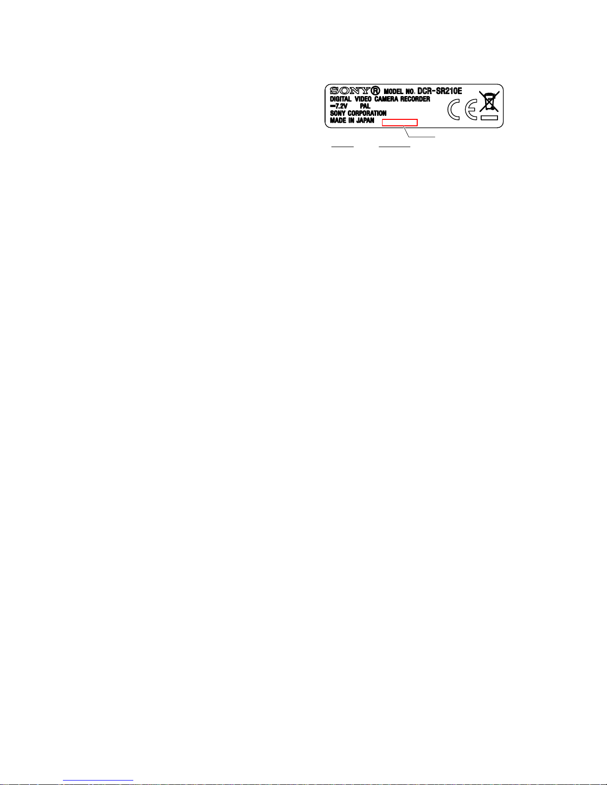
1-6. PRECAUTION ON REPLACING
THE CABINET (G(700)) ASSY
(DCR-SR210E)
The model display adopts the laser printing method.Therefore, the
cabinet (G(700)) assy for replacement differs depending on the
destination.
As similar displays are provided, choose the suitable one for order.
Note1: After replacing the cabinet (G(700)) assy, the serial number
for it will be changed to the one exclusive for service use.
Inform a customer of the serial number change and change the serial
number in the repair data.
(JAPANESE)
1-6.
キャビネット(G(700))組立交換時の注意
(DCR-SR210E)
機種の表示部はレーザー印字方式を採用しております。
この為,交換用のキャビネット(G(700))組立は仕向けによ
り異なります。類似の表示もありますので,該当するもの
を選んで注文して下さい。
注意1: キャビネット(G(700))組立交換後はシリアルナン
バーがサービス専用のシリアルナンバーに変更されます。
お客様への案内と修理データのシリアルナンバー変更を
行ってください。
DCR-SR210E
(AEP, UK Models)
Part No.
A-1517-464-A
Description
CABINET(G(700))(SR210ECEH)
Serial No.
1-14
DCR-SR210E/SR220/SR220D/SR220E/
HDR-SR10/SR10D/SR10E_L2
(ENGLISH)
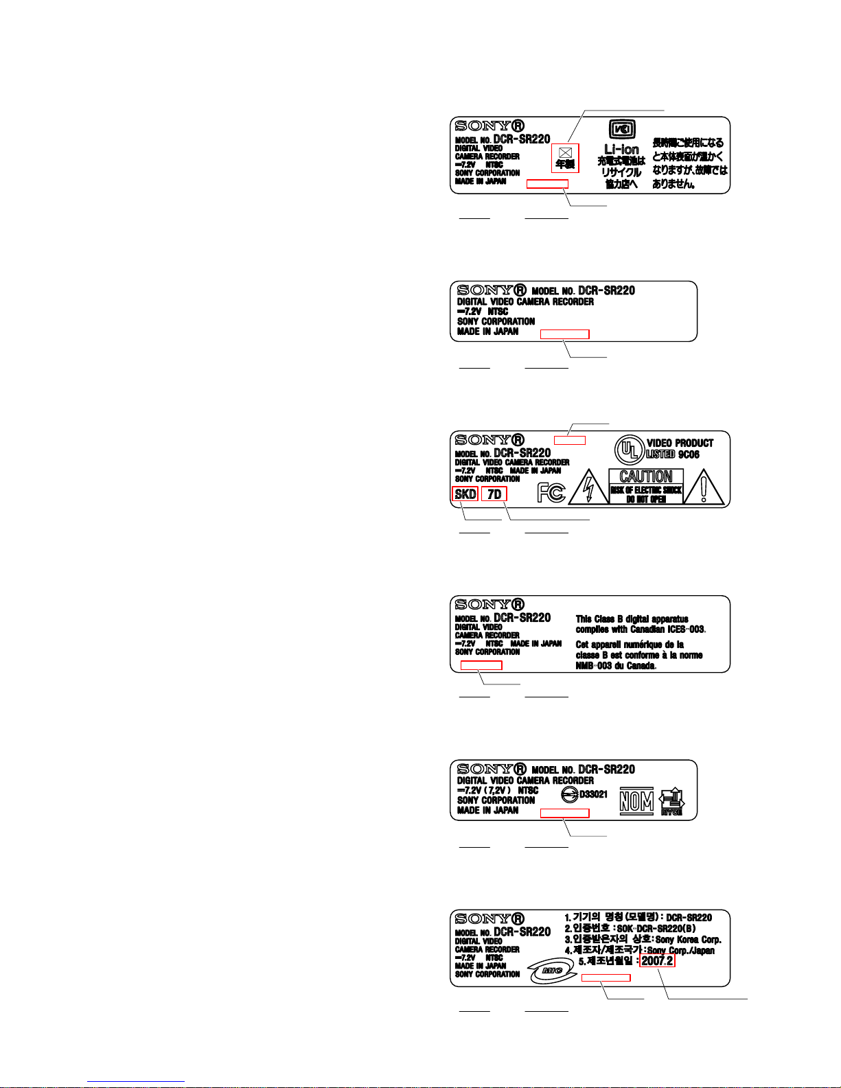
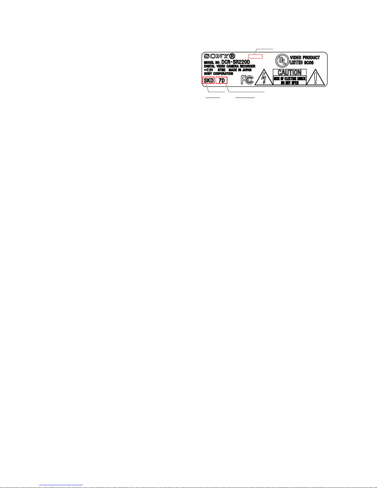
1-7. PRECAUTION ON REPLACING
THE CABINET (G(700)) ASSY
(DCR-SR220)
The model display adopts the laser printing method.Therefore, the
cabinet (G(700)) assy for replacement differs depending on the
destination.
As similar displays are provided, choose the suitable one for order.
Note1: After replacing the cabinet (G(700)) assy, the serial number
for it will be changed to the one exclusive for service use.
Inform a customer of the serial number change and change the serial
number in the repair data.
Note 2: When replacing the cabinet (G(700)) assy for US, affix the
“Manufacturing year” label and the “Factory” label on the specified
location as shown in the figure.
The replacement caution label and inset (how to affix) are supplied
together with the cabinet (G(700)) assy.
Note 3: When replacing the cabinet (G(700)) assy for Korea, af fix
the “Manufacturing year” label on the specified location as shown
in the figure.
The replacement caution label and inset (how to affix) are supplied
together with the cabinet (G(700)) assy.
(JAPANESE)
1-7.
キャビネット(G(700))組立交換時の注意
(DCR-SR220)
機種の表示部はレーザー印字方式を採用しております。
この為,交換用のキャビネット(G(700))組立は仕向けによ
り異なります。類似の表示もありますので,該当するもの
を選んで注文して下さい。
注意1: キャビネット(G(700))組立交換後はシリアルナン
バーがサービス専用のシリアルナンバーに変更されます。
お客様への案内と修理データのシリアルナンバー変更を
行ってください。
注意2: US仕向けキャビネット(G(700))組立を交換した際
は「製造年月」を表すラベルと,「製造所」を表すラベル
を図の指定位置に貼り付けてください。
なお,キャビネット(G(700))組立には時期表示ラベル,投
げ込み(ラベル貼り方)がセットで供給されます。
注意3: Korean仕向けキャビネット(G(700))組立を交換し
た際は,「製造年月」を表すラベルを図の指定位置に貼り
付けてください。
なお,キャビネット(G(700))組立には時期表示ラベル,投
げ込み(ラベル貼り方)がセットで供給されます。
DCR-SR220
(Japanese Model)
Part No.
A-1517-443-A
Description
CABINET(G(700))(SR220J1)
DCR-SR220
(Tourist Model)
Part No.
A-1517-445-A
Description
CABINET(G(700))(SR220JE3)
DCR-SR220
(US Model)
Part No.
A-1517-446-A
Description
CABINET(G(700))(SR220U2)
DCR-SR220
(Canadian Model)
Part No.
A-1517-447-A
Description
CABINET(G(700))(SR220CA2)
DCR-SR220
(E Model)
Part No.
A-1517-448-A
Description
CABINET(G(700))(SR220E23)
DCR-SR220
(Korea Models)
Part No.
A-1517-449-A
Description
CABINET(G(700))(SR220KR2)
*
Manufacturing year
*
Factory* Manufacturing year
Serial No.
Serial No.
Serial No.
Serial No.
Serial No.
Serial No.
*
Manufacturing year
*
Affix the label
*
Affix the label
*
Affix the label
1-15
DCR-SR210E/SR220/SR220D/SR220E/
HDR-SR10/SR10D/SR10E_L2
(ENGLISH)
1-8. PRECAUTION ON REPLACING
THE CABINET (G(700)) ASSY
(DCR-SR220D)
The model display adopts the laser printing method.Therefore, the
cabinet (G(700)) assy for replacement differs depending on the
destination.
As similar displays are provided, choose the suitable one for order.
Note1: After replacing the cabinet (G(700)) assy, the serial number
for it will be changed to the one exclusive for service use.
Inform a customer of the serial number change and change the serial
number in the repair data.
Note 2: When replacing the cabinet (G(700)) assy for US, affix the
“Manufacturing year” label and the “Factory” label on the specified
location as shown in the figure.
The replacement caution label and inset (how to affix) are supplied
together with the cabinet (G(700)) assy.
(JAPANESE)
1-8.
キャビネット(G(700))組立交換時の注意
(DCR-SR220D)
機種の表示部はレーザー印字方式を採用しております。
この為,交換用のキャビネット(G(700))組立は仕向けによ
り異なります。類似の表示もありますので,該当するもの
を選んで注文して下さい。
注意1: キャビネット(G(700))組立交換後はシリアルナン
バーがサービス専用のシリアルナンバーに変更されます。
お客様への案内と修理データのシリアルナンバー変更を
行ってください。
注意2: US仕向けキャビネット(G(700))組立を交換した際
は「製造年月」を表すラベルと,「製造所」を表すラベル
を図の指定位置に貼り付けてください。
なお,キャビネット(G(700))組立には時期表示ラベル,投
げ込み(ラベル貼り方)がセットで供給されます。
DCR-SR220D
(US Model)
Part No.
A-1517-450-A
Description
CABINET(G(700))(SR220DU2)
*
Factory* Manufacturing year
Serial No.
1-16
DCR-SR210E/SR220/SR220D/SR220E/
HDR-SR10/SR10D/SR10E_L2
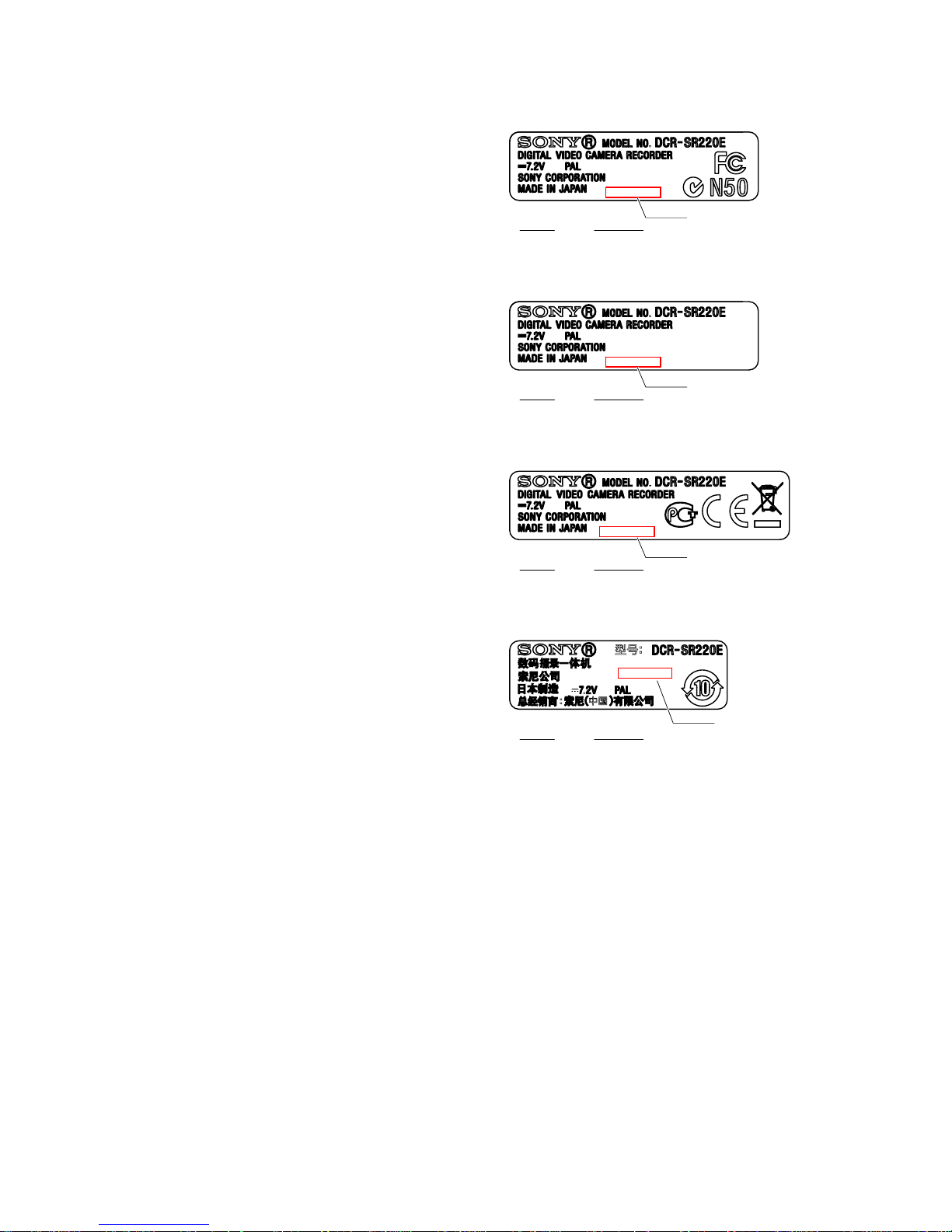
DCR-SR220E
(E, Hong Kong, Vietnamese, Austrarian Models)
Part No.
A-1517-459-A
Description
CABINET(G(700))(SR220EE34)
DCR-SR220E
(Tourist Model)
Part No.
A-1517-460-A
Description
CABINET(G(700))(SR220EJE3)
DCR-SR220E
(North European Model)
Part No.
A-1517-461-A
Description
CABINET(G(700))(SR220ECEL)
DCR-SR220E
(Chinese Model)
Part No.
A-1517-462-A
Description
CABINET(G(700))(SR220ECN2)
Serial No.
Serial No.
Serial No.
Serial No.
(ENGLISH)
1-9. PRECAUTION ON REPLACING
THE CABINET (G(700)) ASSY
(DCR-SR220E)
The model display adopts the laser printing method.Therefore, the
cabinet (G(700)) assy for replacement differs depending on the
destination.
As similar displays are provided, choose the suitable one for order.
Note1: After replacing the cabinet (G(700)) assy, the serial number
for it will be changed to the one exclusive for service use.
Inform a customer of the serial number change and change the serial
number in the repair data.
(JAPANESE)
1-9.
キャビネット(G(700))組立交換時の注意
(DCR-SR220E)
機種の表示部はレーザー印字方式を採用しております。
この為,交換用のキャビネット(G(700))組立は仕向けによ
り異なります。類似の表示もありますので,該当するもの
を選んで注文して下さい。
注意1: キャビネット(G(700))組立交換後はシリアルナン
バーがサービス専用のシリアルナンバーに変更されます。
お客様への案内と修理データのシリアルナンバー変更を
行ってください。

1-17
DCR-SR210E/SR220/SR220D/SR220E/
HDR-SR10/SR10D/SR10E_L2
HDR-SR10
(Tourist Model)
Part No.
A-1517-465-A
Description
CABINET(G(700))(SR10JE3)
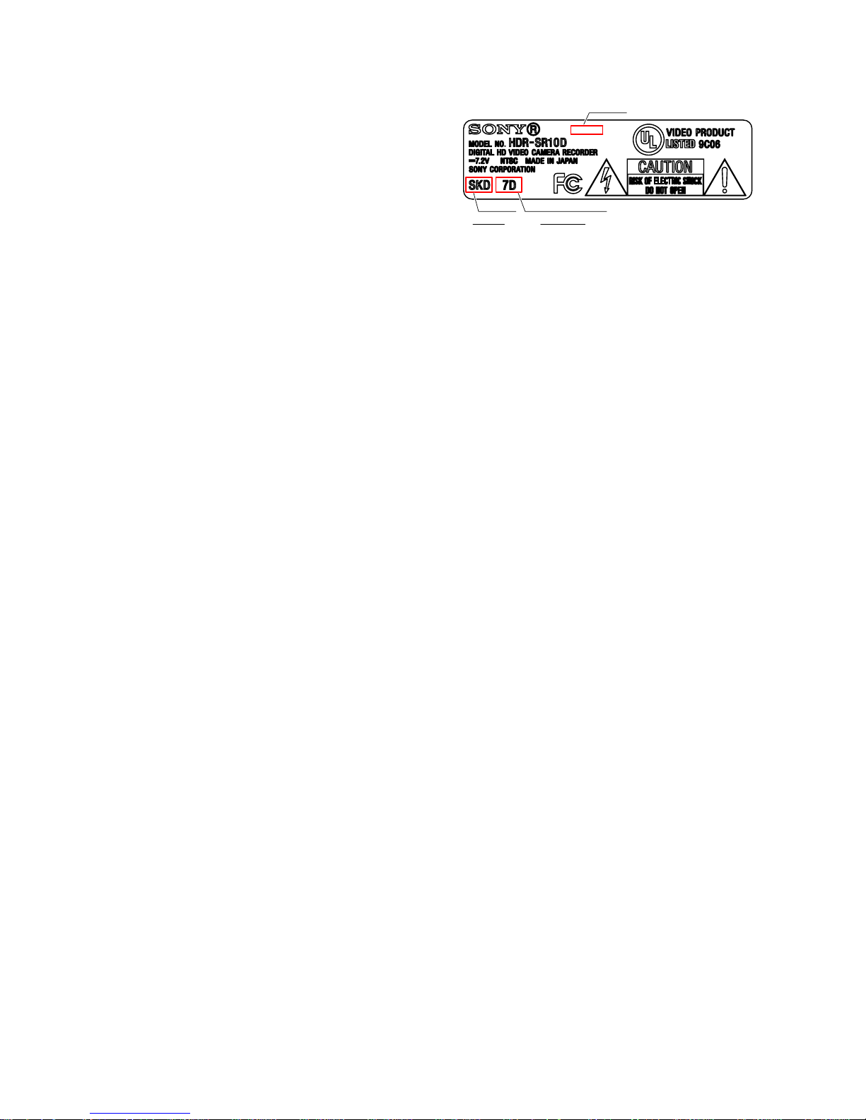
HDR-SR10
(US Model)
Part No.
A-1517-466-A
Description
CABINET(G(700))(SR10U2)
HDR-SR10
(Canadian Model)
Part No.
A-1517-467-A
Description
CABINET(G(700))(SR10CA2)
HDR-SR10
(Korea Model)
Part No.
A-1517-470-A
Description
CABINET(G(700))(SR10KR2)
HDR-SR10
(E Model)
Part No.
A-1517-469-A
Description
CABINET(G(700))(SR10E23)
*
Factory* Manufacturing year
Serial No.
*
Manufacturing year
*
Affix the label
*
Affix the label
Serial No.
Serial No.
Serial No.
Serial No.
(ENGLISH)
1-10. PRECAUTION ON REPLACING
THE CABINET (G(700)) ASSY
(HDR-SR10)
The model display adopts the laser printing method.Therefore, the
cabinet (G(700)) assy for replacement differs depending on the
destination.
As similar displays are provided, choose the suitable one for order.
Note1: After replacing the cabinet (G(700)) assy, the serial number
for it will be changed to the one exclusive for service use.
Inform a customer of the serial number change and change the serial
number in the repair data.
Note 2: When replacing the cabinet (G(700)) assy for US, affix the
“Manufacturing year” label and the “Factory” label on the specified
location as shown in the figure.
The replacement caution label and inset (how to affix) are supplied
together with the cabinet (G(700)) assy.
Note 3: When replacing the cabinet (G(700)) assy for Korea, af fix
the “Manufacturing year” label on the specified location as shown
in the figure.
The replacement caution label and inset (how to affix) are supplied
together with the cabinet (G(700)) assy.
(JAPANESE)
1-10.
キャビネット(G(700))組立交換時の注意
(HDR-SR10)
機種の表示部はレーザー印字方式を採用しております。
この為,交換用のキャビネット(G(700))組立は仕向けによ
り異なります。類似の表示もありますので,該当するもの
を選んで注文して下さい。
注意1: キャビネット(G(700))組立交換後はシリアルナン
バーがサービス専用のシリアルナンバーに変更されます。
お客様への案内と修理データのシリアルナンバー変更を
行ってください。
注意2: US仕向けキャビネット(G(700))組立を交換した際
は「製造年月」を表すラベルと,「製造所」を表すラベル
を図の指定位置に貼り付けてください。
なお,キャビネット(G(700))組立には時期表示ラベル,投
げ込み(ラベル貼り方)がセットで供給されます。
注意3: Korean仕向けキャビネット(G(700))組立を交換し
た際は,「製造年月」を表すラベルを図の指定位置に貼り
付けてください。
なお,キャビネット(G(700))組立には時期表示ラベル,投
げ込み(ラベル貼り方)がセットで供給されます。
1-18
DCR-SR210E/SR220/SR220D/SR220E/
HDR-SR10/SR10D/SR10E_L2
HDR-SR10D
(US Model)
Part No.
A-1517-471-A
Description
CABINET(G(700))(SR10DU2)
*
Factory* Manufacturing year
Serial No.
*
Affix the label
(ENGLISH)
1-11. PRECAUTION ON REPLACING
THE CABINET (G(700)) ASSY
(HDR-SR10D)
The model display adopts the laser printing method.Therefore, the
cabinet (G(700)) assy for replacement differs depending on the
destination.
As similar displays are provided, choose the suitable one for order.
Note1: After replacing the cabinet (G(700)) assy, the serial number
for it will be changed to the one exclusive for service use.
Inform a customer of the serial number change and change the serial
number in the repair data.
Note 2: When replacing the cabinet (G(700)) assy for US, affix the
“Manufacturing year” label and the “Factory” label on the specified
location as shown in the figure.
The replacement caution label and inset (how to affix) are supplied
together with the cabinet (G(700)) assy.
(JAPANESE)
1-11.
キャビネット(G(700))組立交換時の注意
(HDR-SR10D)
機種の表示部はレーザー印字方式を採用しております。
この為,交換用のキャビネット(G(700))組立は仕向けによ
り異なります。類似の表示もありますので,該当するもの
を選んで注文して下さい。
注意1: キャビネット(G(700))組立交換後はシリアルナン
バーがサービス専用のシリアルナンバーに変更されます。
お客様への案内と修理データのシリアルナンバー変更を
行ってください。
注意2: US仕向けキャビネット(G(700))組立を交換した際
は「製造年月」を表すラベルと,「製造所」を表すラベル
を図の指定位置に貼り付けてください。
なお,キャビネット(G(700))組立には時期表示ラベル,投
げ込み(ラベル貼り方)がセットで供給されます。
1-19E
DCR-SR210E/SR220/SR220D/SR220E/
HDR-SR10/SR10D/SR10E_L2
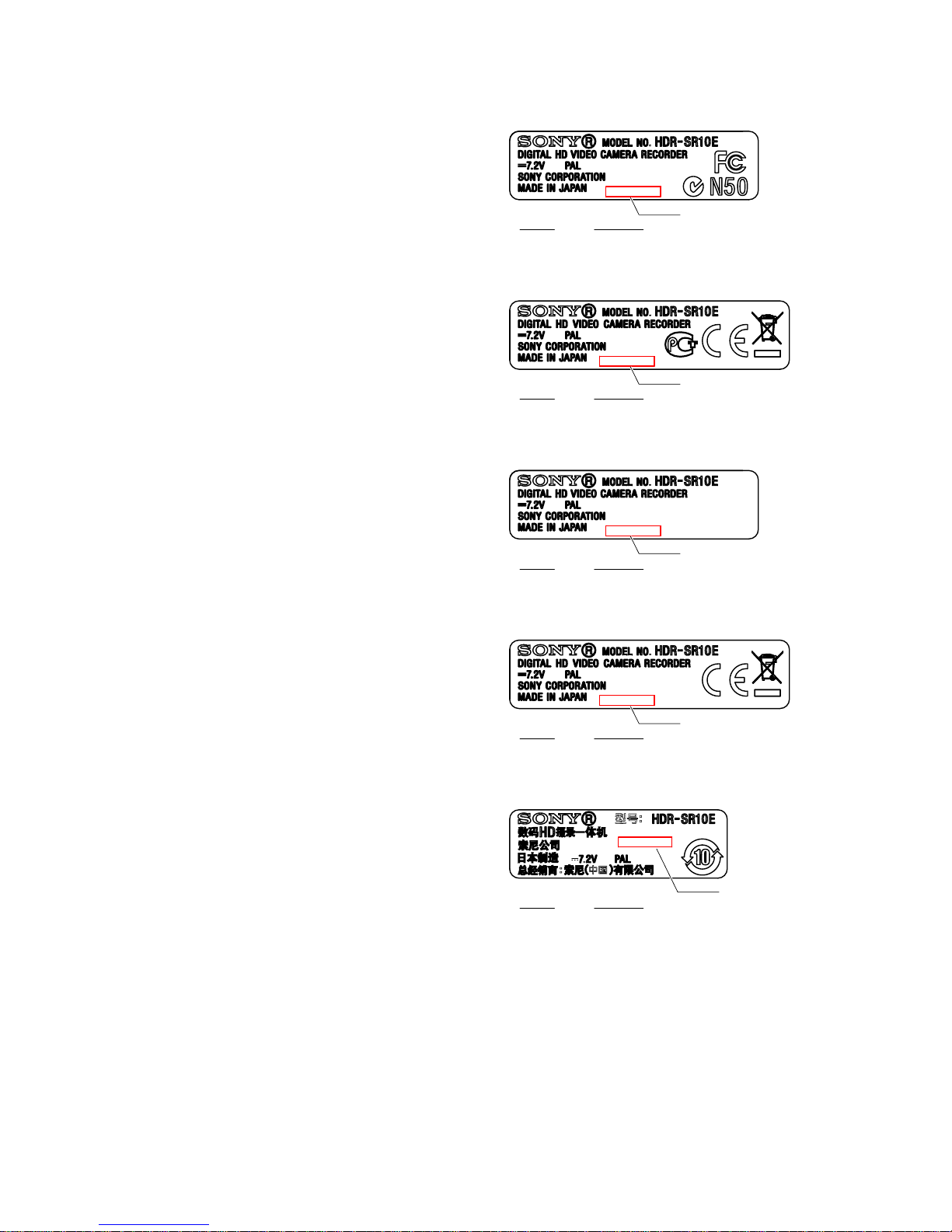
(ENGLISH)
1-12.PRECAUTION ON REPLACING
THE CABINET (G(700)) ASSY
(HDR-SR10E)
The model display adopts the laser printing method.Therefore, the
cabinet (G(700)) assy for replacement differs depending on the
destination.
As similar displays are provided, choose the suitable one for order.
Note1: After replacing the cabinet (G(700)) assy, the serial number
for it will be changed to the one exclusive for service use.
Inform a customer of the serial number change and change the serial
number in the repair data.
(JAPANESE)
1-12.
キャビネット(G(700))組立交換時の注意
(HDR-SR10E)
機種の表示部はレーザー印字方式を採用しております。
この為,交換用のキャビネット(G(700))組立は仕向けによ
り異なります。類似の表示もありますので,該当するもの
を選んで注文して下さい。
注意1: キャビネット(G(700))組立交換後はシリアルナン
バーがサービス専用のシリアルナンバーに変更されます。
お客様への案内と修理データのシリアルナンバー変更を
行ってください。
HDR-SR10E
(E,Hong Kong, Australian Models)
Part No.
A-1517-472-A
Description
CABINET(G(700))(SR10EE34)
HDR-SR10E
(North European Models)
Part No.
A-1517-473-A
Description
CABINET(G(700))(SR10ECEL)
HDR-SR10E
(Tourist Model)
Part No.
A-1517-474-A
Description
CABINET(G(700))(SR10EJE3)
HDR-SR10E
(AEP, UK Model)
Part No.
A-1517-475-A
Description
CABINET(G(700))(SR10ECEH)
HDR-SR10E
(Chinese Model)
Part No.
A-1517-476-A
Description
CABINET(G(700))(SR10ECN2)
Serial No.
Serial No.
Serial No.
Serial No.
Serial No.
2-1
2. DISASSEMBLY
DCR-SR210E/SR220/SR220D/SR220E/
HDR-SR10/SR10D/SR10E_L2
NOTE FOR REPAIR
• Make sure that the flat cable and flexible board are not cracked of bent at the terminal.
Do not insert the cable insufficiently nor crookedly.
• When remove a connector, don’t pull at wire of connector. It is possible that a wire is snapped.
• When installing a connector, don’t press down at wire of connector.
It is possible that a wire is snapped.
Cut and remove the part of gilt
which comes off at the point.
(Be careful or some
pieces of gilt may be left inside)
DISCHARGING OF THE ST-189 BOARD’S CHARGING CAPACITOR (C5056)
The charging capacitor (C5056) of the ST-189 board is charged
up to the maximum 330 V potential.
There is a danger of electric shock by this high voltage when the
capacitor is handled by hand. The electric shock is caused by
the charged voltage which is kept without discharging when the
main power of the unit is simply turned off. Therefore, the
remaining voltage must be discharged as described below.
Preparing the Short Jig
To preparing the short jig, a small clip is attached to each end of
a resistor of 1 kΩ /1 W (1-215-869-11).
Wrap insulating tape fully around the leads of the resistor to
prevent electrical shock.
NOTE FOR DISCONNECTING THE HARNESS (HN-058)
When disconnecting the harness (HN-058), do not pull the
harness part but pull off the connector body with tweezers etc.
Harness
(HN-058)
Tweezers etc.
1 kΩ/1 W
Wrap insulating tape.
C5056
Note: High-voltage cautions
Discharging the Capacitor
Short-circuit between the two points
with the short jig about 10 seconds.
ST-189 Board
R:1 kΩ/1 W
(Part code: 1-215-869-11)
2-2
DCR-SR210E/SR220/SR220D/SR220E/
HDR-SR10/SR10D/SR10E_L2
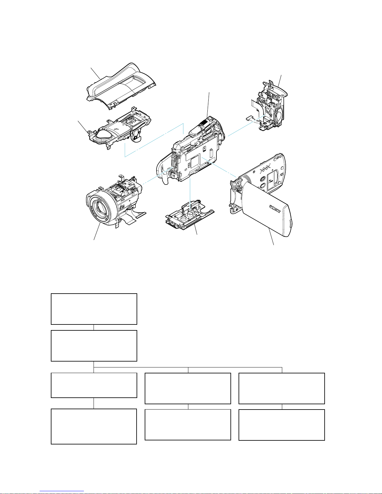
2-1. IDENTIFYING PARTS
2-2-1. OVERALL SECTION-1
- Cabinet (G) Assy
- HDD
- Bottom Cabinet Block
2-2-2. OVERALL SECTION-2
- Cabinet (R) Section
- Cabinet (Top) Block
- BT Panel Block
2-2-3. OVERALL SECTION-3
- Cabinet (F) Section
- VC-516 Board
2-2-5. CABINET (F) SECTION
- Lens Block
- FR-285 Board
- Lens Barrier Unit
2-2-6. LENS BLOCK
- ST-189 Board
- LD-230 Board
- Flash Unit
2-2-7. CABINET (R) SECTION
- Loud Speaker
- CK-196 Board
- Panel Block
2-2-8. PANEL BLOCK
- Hinge Assy
- LCD
- PD-356 Board
- DISASSEMBLY FLOW -
2-2-4. CABINET (L) SECTION
- JK-366 Board
- Control Switch Block (PS28100)
- FP-855 Flexible Board
(HDR-SR10/SR10D/SR10E)
Cabinet (R) Section
⋅ CK-196 Board
⋅
PD-356 Board
Cabinet (L) Section
⋅ VC-516 Board
⋅
JK-366 Board
Cabinet (F) Section
⋅ FR-285 Board
⋅
ST-189 Board
⋅
LD-230 Board
BT Panel Block
⋅ MS-397 Board
Top Assy
Cabinet (Top)
Block Assy
Bottom Cabinet Block
⋅ CR-091 Board
 Loading...