

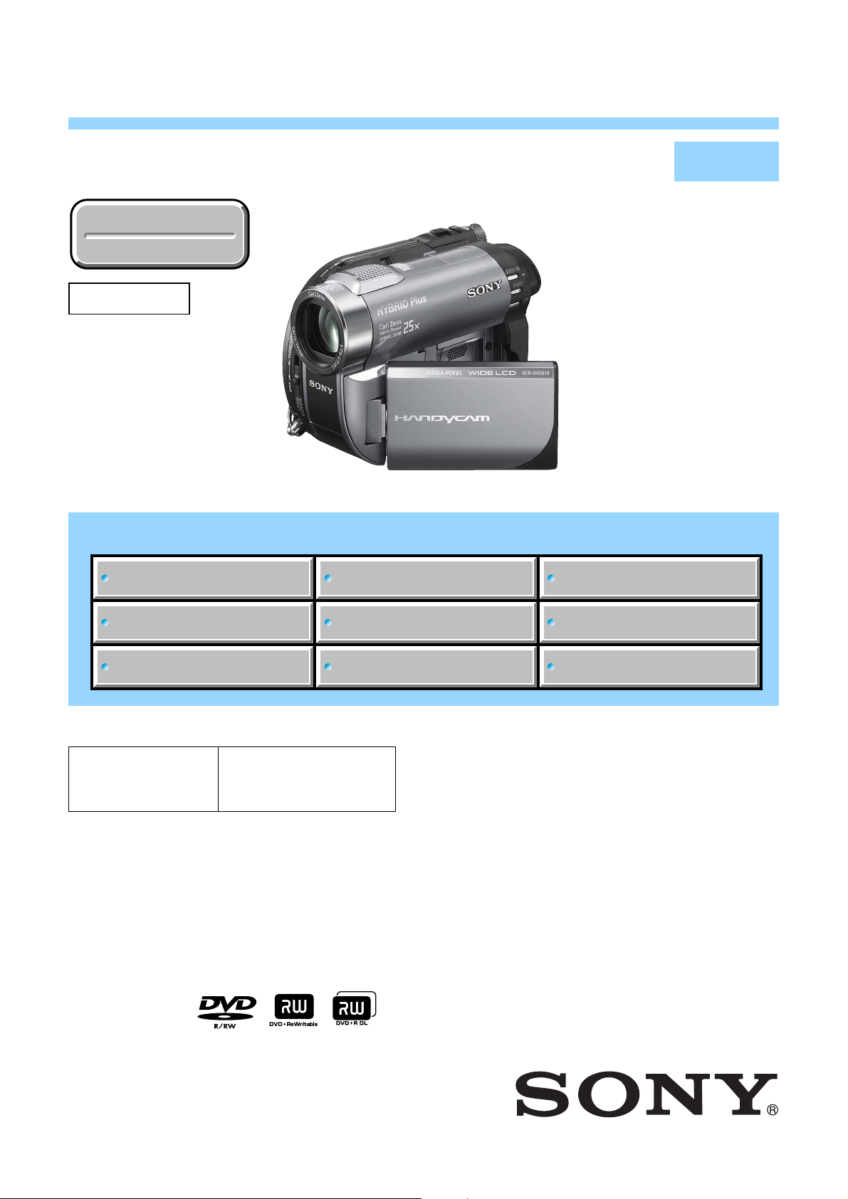
Sony DCR-DVD610 Schematic
DCR-DVD110E/DVD115E/DVD310E/DVD410E/DVD610/
DVD610E/DVD710/DVD710E/DVD810/DVD810E
RMT-835
SERVICE MANUAL
Ver. 1.4 2008.11
Revision History
Revision History
Revised-2
Replace the previously issued
SERVICE MANUAL 9-852-249-33
with this manual.
Photo: DCR-DVD810
Link
Link
SPECIFICATIONS
DISASSEMBLY
LEVEL 2
US Model
Canadian Model
AEP Model
UK Model
East European Model
North European Model
E Model
Australian Model
Hong Kong Model
Chinese Model
Korea Model
Argentine Model
Brazilian Model
Thai Model
Tourist Model
Japanese Model
SCHEMATIC DIAGRAMS
MODEL INFORMATION TABLE
SERVICE NOTE
• Precaution on Replacing the VC-520 Board
The components identified by
mark 0 or dotted line with
mark 0 are critical for safety.
Replace only with part number specified.
Les composants identifiés par une
marque 0 sont critiques pour la
sécurité.
Ne les remplacer que par une pièce
portant le numéro spécifié.
BLOCK DIAGRAMS
FRAME SCHEMATIC DIAGRAM
PRINTED WIRING BOARDS
REPAIR PARTS LIST
DIGITAL VIDEO CAMERA RECORDER
DCR-DVD110E/DVD115E/DVD310E/DVD410E/DVD610/
DVD610E/DVD710/DVD710E/DVD810/DVD810E_L2
Sony EMCS Co.
2008K0500-1
© 2008.11
Published by Kohda TEC9-852-249-34

These specifications are extracted from instruction manual of DCRDVD110E/DVD115E/DVD310E/DVD410E/DVD610E/DVD710E/DVD810E.
SPECIFICATIONS
System
Video compression format
MPEG2/JPEG (Still images)
Audio compression format
DCR-DVD110E/DVD610E
Dolby Digital 2ch
Dolby Digital Stereo Creator
DCR-DVD115E/DVD310E/DVD410E/
DVD710E/DVD810E
Dolby Digital 2/5.1ch
Dolby Digital 5.1 Creator
Video signal
PAL color, CCIR standards
Internal memory (DCR-DVD410E/
DVD810E)
8GB
When measuring media capacity, 1 GB equals
1 billion bytes, a portion of which is used for
data management.
Usable discs
8 cm DVD-RW/DVD+RW/DVD-R/
DVD+R DL
Movie recording format
Internal memory (DCR-DVD410E/
DVD810E)
MPEG2-PS
Disc
DVD-RW: DVD-VIDEO (VIDEO mode),
DVD-Video Recording (VR mode)
DVD+RW: DVD+RW Video
DVD-R/DVD+R DL: DVD-VIDEO
“Memory Stick PRO Duo”
MPEG2-PS
Still image recording format
Exif Ver.2.2
*
Viewfinder
Electric viewfinder (color)
Image device
DCR-DVD110E/DVD115E/DVD610E
2.25 mm (1/8 type) CCD (Charge Coupled
Device)
Gross:
Approx. 800 000 pixels
Effective (Movie, 16:9)
Approx. 490 000 pixels
Effective (Still, 16:9)
Approx. 310 000 pixels
Effective (Still, 4:3)
Approx. 410 000 pixels
DCR-DVD310E/DVD410E/DVD710E/
DVD810E
3 mm (1/6 type) CCD (Charge Coupled
Device)
Gross:
Approx. 1 070 000 pixels
Effective (Movie, 16:9)
Approx. 670 000 pixels
Effective (Still, 16:9)
Approx. 750 000 pixels
Effective (Still, 4:3)
Approx. 1 000 000 pixels
Lens
Carl Zeiss Vario-Tessar
DCR-DVD110E/DVD115E/DVD610E
Optical: 40×, Digital: 80×, 2000×
DCR-DVD310E/DVD410E/DVD710E/
DVD810E
Optical: 25×, Digital: 50×, 2000×
Filter diameter: 30 mm (1 3/16 in.)
Focal length
DCR-DVD110E/DVD115E/DVD610E
F1.8 - 4.1
f=1.9 - 76 mm (3/32 - 3 in.)
When converted to a 35 mm still camera
For movies:
41 - 1 640 mm (1 5/8 - 64 5/8 in.) (16:9)
For still images:
48 - 1 920 mm (1 15/16 - 75 5/8 in.) (4:3)
DCR-DVD310E/DVD410E/DVD710E/
DVD810E
F1.8 - 3.2
f=2.5 - 62.5 mm (1/8 - 2 1/2 in.)
When converted to a 35 mm still camera
For movies:
41 - 1 189 mm (1 5/8 - 46 7/8 in.) (16:9)
For still images:
36 - 900 mm (1 7/16 - 35 1/2 in.) (4:3)
Color temperature
[AUTO], [ONE PUSH], [INDOOR]
(3 200 K), [OUTDOOR] (5 800 K)
Minimum illumination
DCR-DVD110E/DVD115E/DVD610E
6lx (lux) (AUTO S LW SHUTTR ON, Shutter
speed 1/25 second)
0lx (lux) (during NightShot plus function)
DCR-DVD310E/DVD410E/DVD710E/
DVD810E
8lx (lux) (AUTO S LW SHUTTR ON, Shutter
speed 1/25 second)
0lx (lux) (during NightShot plus function)
* “Exif” is a file format for still images,
established by the JEITA (Japan Electronics and
Information Technology Industries
Association). Files in this format can have
additional information such as your camcorder’s
setting information at the time of recording.
**The focal length figures are actual figures
resulting from wide angle pixel readout.
• Manufactured under license from Dolby
Laboratories.
Input/Output connectors
A/V Remote Connector
Video/audio output jack
USB jack
mini-B
(DCR-DVD110E/DVD115E/DVD310E/
DVD410E: output only)
LCD screen
Picture
6.7 cm (2.7 type, aspect ratio 16:9)
Total number of pixels
123 200 (560 × 220)
General
Power requirements
DC 6.8 V/7.2 V (battery pack)
DC 8.4 V (AC Adaptor)
Average power consumption
Using the LCD screen or the viewfinder with
normal brightness
DCR-DVD110E/DVD115E/DVD610E
LCD: 2.9 W
Viewfinder: 2.7 W
DCR-DVD310E/DVD710E
LCD: 3.2 W
Viewfinder: 2.8 W
DCR-DVD410E/DVD810E
LCD: 2.8 W
Viewfinder: 2.4 W
**
ENGLISH JAPANESE
ENGLISH JAPANESE
Operating temperature
0 °C to +40 °C (32 °F to 104 °F)
Storage temperature
-20 °C to +60 °C (-4 °F to +140 °F)
Dimensions (Approx.)
55 × 89 × 130mm (2 1/4 × 3 5/8 × 5 1/8 in.)
(w × h × d) including the projecting parts
55 × 89 × 130mm (2 1/4 × 3 5/8 × 5 1/8 in.)
(w × h × d) including the projecting parts with
the rechargeable battery pack NP-FH40
attached
Mass (Approx.)
DCR-DVD110E/DVD115E/DVD610E
390 g (13oz) main unit only
440 g (15oz) including the rechargeable
battery pack NP-FH40 and a disc
DCR-DVD310E/DVD710E
400 g (14oz) main unit only
450 g (15oz) including the rechargeable
battery pack NP-FH40 and a disc
DCR-DVD410E/DVD810E
400 g (14oz)main unit only
445 g (15oz) including the rechargeable
battery pack NP-FH40
Supplied accessories
AC Adaptor (1)
Power cord (mains lead) (1)
A/V connecting cable (1)
USBcable (1)
Wireless Remote Commander (DCRDVD310E/DVD410E/DVD710E/DVD810E)
(1)
Rechargeable battery pack NP-FH40 (1)
CD-ROM “Handycam Application Software”
(1)
Operating Guide (1)
See page 5-25.
AC Adaptor AC-L200/L200B
Power requirements
AC 100 V - 240 V, 50/60 Hz
Current consumption
0.35 A - 0.18 A
Power consumption
18 W
Output voltage
DC 8.4 V*
Operating temperature
0 °C to +40 °C (32 °F to 104 °F)
Storage temperature
-20 °C to +60 °C (-4 °F to +140 °F)
Dimensions (Approx.)
48 × 29 × 81mm (1 15/16 × 1 3/16 × 3 1/4in.)
(w × h × d) excluding the projecting parts
Mass (Approx.)
170g (6oz) excluding the power cord
(mains lead)
* See at the label of the AC Adaptor for other
specifications.
Rechargeable battery pack NP-FH40
Maximum output voltage
DC 8.4 V
Output voltage
DC 7.2 V
Capacity
4.9 Wh (680 mAh)
Type
Li-ion
Design and specifications are subject to change
without notice.
DCR-DVD110E/DVD115E/DVD310E/DVD410E/DVD610/
DVD610E/DVD710/DVD710E/DVD810/DVD810E_L2
— 2 —

These specifications are extracted from instruction
manual of DCR-DVD610/DVD710/DVD810.
SPECIFICATIONS
ENGLISH JAPANESE
ENGLISH JAPANESE
System
Video compression format
MPEG2/JPEG (Still images)
Audio compression format
DCR-DVD610
Dolby Digital 2ch
Dolby Digital Stereo Creator
DCR-DVD710/DVD810
Dolby Digital 2/5.1ch
Dolby Digital 5.1 Creator
Video signal
NTSC color, EIA standards
Internal memory (DCR-DVD810)
8GB
When measuring media capacity, 1 GB equals
1 billion bytes, a portion of which is used for
data management.
Usable discs
8 cm DVD-RW/DVD+RW/DVD-R/
DVD+R DL
Movie recording format
Internal memory (DCR-DVD810)
MPEG2-PS
Disc
DVD-RW: DVD-VIDEO (VIDEO mode),
DVD-Video Recording (VR mode)
DVD+RW: DVD+RW Video
DVD-R/DVD+R DL: DVD-VIDEO
“Memory Stick PRO Duo”
MPEG2-PS
Still image recording format
Exif Ver.2.2
*
Viewfinder
Electric viewfinder (color)
Image device
DCR-DVD610
2.25 mm (1/8 type) CCD (Charge Coupled
Device)
Gross:
Approx. 680 000 pixels
Effective (Movie, 16:9)
Approx. 410 000 pixels
Effective (Still, 16:9)
Approx. 250 000 pixels
Effective (Still, 4:3)
Approx. 340 000 pixels
DCR-DVD710/DVD810
3 mm (1/6 type) CCD (Charge Coupled
Device)
Gross:
Approx. 1 070 000 pixels
Effective (Movie, 16:9)
Approx. 670 000 pixels
Effective (Still, 16:9)
Approx. 750 000 pixels
Effective (Still, 4:3)
Approx. 1 000 000 pixels
Lens
Carl Zeiss Vario-Tessar
DCR-DVD610
Optical: 40×, Digital: 80×, 2000×
DCR-DVD710/DVD810
Optical: 25×, Digital: 50×, 2000×
Filter diameter: 30 mm (1 3/16 in.)
Focal length
DCR-DVD610
F1.8 - 4.1
f=1.9 - 76 mm (3/32 - 3 in.)
When converted to a 35 mm still camera
For movies:
41 - 1 640 mm (1 5/8 - 64 5/8 in.) (16:9)
For still images:
48 - 1 920 mm (1 15/16 - 75 5/8 in.) (4:3)
DCR-DVD710/DVD810
F1.8 - 3.2
f=2.5 - 62.5 mm (1/8 - 2 1/2 in.)
When converted to a 35 mm still camera
For movies:
41 - 1 189 mm (1 5/8 - 46 7/8 in.) (16:9)
For still images:
36 - 900 mm (1 7/16 - 35 1/2 in.) (4:3)
Color temperature
[AUTO], [ONE PUSH], [INDOOR]
(3 200 K), [OUTDOOR] (5 800 K)
Minimum illumination
DCR-DVD610
6lx ( lux) (AUTO SLW SHUTTR ON, Shutter
speed 1/30 second)
0lx (lux) (during NightShot plus function)
DCR-DVD710/DVD810
8lx ( lux) (AUTO SLW SHUTTR ON, Shutter
speed 1/30 second)
0lx (lux) (during NightShot plus function)
* “Exif” is a file format for still images,
established by the JEITA (Japan Electronics and
Information Technology Industries
Association). Files in this format can have
additional information such as your camcorder’s
setting information at the time of recording.
**The focal length figures are actual figures
resulting from wide angle pixel readout.
• Manufactured under license from Dolby
Laboratories.
Input/Output connectors
A/V Remote Connector
Video/audio output jack
USB jack
mini-B
LCD screen
Picture
6.7 cm (2.7 type, aspect ratio 16:9)
Total number of pixels
123 200 (560 × 220)
General
Power requirements
DC 6.8 V/7.2 V (battery pack)
DC 8.4 V (AC Adaptor)
Average power consumption
Using the LCD screen or the viewfinder with
normal brightness
DCR-DVD610
LCD: 2.9 W
Viewfinder: 2.7 W
DCR-DVD710
LCD: 3.3 W
Viewfinder: 2.9 W
DCR-DVD810
LCD: 2.9 W
Viewfinder: 2.5 W
Operating temperature
0 °C to +40 °C (32 °F to 104 °F)
Storage temperature
-20 °C to +60 °C (-4 °F to +140 °F)
Dimensions (Approx.)
55 × 89 × 130mm (2 1/4 × 3 5/ × 5 1/8 in.)
(w × h × d) including the projecting parts
55 × 89 × 130mm (2 1/4 × 3 5/8 × 5 1/8 in.)
(w × h × d) including the projecting parts with
the rechargeable battery pack NP-FH40
attached
Mass (Approx.)
DCR-DVD610
**
390 g (13oz) main unit only
440g (15 oz) including the rechargeable
battery pack NP-FH40 and a disc
DCR-DVD710
400 g (14oz) main unit only
450g (15 oz) including the rechargeable
battery pack NP-FH40 and a disc
DCR-DVD810
400g (14 oz)main unit only
445g (15 oz) including the rechargeable
battery pack NP-FH40
Supplied accessories
AC Adaptor (1)
Power cord (mains lead) (1)
A/V connecting cable (1)
USB cable (1)
Wireless Remote Commander (DCRDVD710/DVD810) (1)
Rechargeable battery pack NP-FH40 (1)
CD-ROM “Handycam Application Software”
(1)
Operating Guide (1)
See page 5-25.
AC Adaptor AC-L200/L200B
Power requirements
AC 100 V - 240 V, 50/60 Hz
Current consumption
0.35 A - 0.18 A
Power consumption
18 W
Output voltage
DC 8.4 V*
Operating temperature
0 °C to +40 °C (32 °F to 104 °F)
Storage temperature
-20 °C to +60 °C (-4 °F to +140 °F)
Dimensions (Approx.)
48 × 29 × 81mm (1 15/16 × 1 3/16 × 3 1/4 in.)
(w × h × d) excluding the projecting parts
Mass (Approx.)
170g (6 oz) excluding the power cord (mains
lead)
* See at the label of the AC Adaptor for other
specifications.
Rechargeable battery pack NP-FH40
Maximum output voltage
DC 8.4 V
Output voltage
DC 7.2 V
Capacity
4.9Wh (680 mAh)
Type
Li-ion
Design and specifications are subject to change
without notice.
DCR-DVD110E/DVD115E/DVD310E/DVD410E/DVD610/
DVD610E/DVD710/DVD710E/DVD810/DVD810E_L2
— 3 —

システム
映像圧縮方式
MPEG2/JPEG
音声圧縮方式
(静止画)
Dolby Digital2/5.1ch
ドルビーデジタル
映像信号
内蔵メモリー
NTSC
カラー、
クリエーター搭載
5.1
標準方式
EIA
8GB
容量は、
の数値です。また管理用ファイルなどを含む
ため、実際使用できる容量は若干減少する場
合があります。
使用可能ディスク
8cmのDVD-RW/DVD+RW/DVD-R/
DVD+R DL
動画記録方式
内蔵メモリー:
ディスク:
DVD-RW:
DVD-VIDEO
DVD-Video Recording(VR
DVD+RW: DVD+RW Video
億バイトで計算した場合
1GBを10
MPEG2-PS
(
VIDEO
モード)
モード)
DVD-R/DVD+R DL: DVD-VIDEO
メモリースティック
MPEG2-PS
静止画記録方式
PRO
デュオ:
Exif Ver.2 .2*
ファインダー
電子ファインダー(カラー)
撮像素子
3.0mm(1/6
総画素数:約
動画時有効画素数(
約
67
静止画時有効画素数(
約
75
静止画時有効画素数(
約
100
万画素
万画素
万画素
型)
107
固体映像素子
CCD
万画素
16:9
16:9
4:3
モード):
モード):
モード):
ズームレンズ
カール ツァイス バリオテッサー
倍(光学)
25
倍、
50
フィルター径
F1.8
f=2.5
35mm
動画撮影時:
41〜1 189mm(16:9
静止画撮影時:
36〜900mm(4:3
色温度切り換え
[オート]、[ワンプッシュ]、
[屋内](
倍(デジタル)
2 000
30mm
〜
3.2
〜
62.5mm
カメラ換算では
)、[屋外](
3 200K
モード)
モード)
**
5 800K
)
概略仕様
最低被写体照度
(ルクス)(オートスローシャッター 入、
8 lx
シャッタースピード
(ルクス)(
0 lx
*
(社)電子情報技術産業協会(
された、撮影情報などの付帯情報を追加する
ことができる静止画用のファイルフォーマッ
ト。
**
広角画素読み出しによる実動作値
NightShot plus
入/出力端子
リモート端子
A/V
映像音声出力端子
端子
USB
mini-B
液晶画面
画面サイズ
6.7cm(2.7
総ドット数
123 200
横
560
×縦
型、アスペクト比
ドット
220
電源部、その他
電源電圧
バッテリー端子入力
端子入力
DC
消費電力
ファインダー使用時、明るさ標準:
2.5W
液晶画面使用時、明るさ標準:
2.9W
動作温度
℃〜
0
保存温度
−
20
外形寸法
55×89×130mm
起部含む)
55×89×130mm
起部含む、付属バッテリー
態)
本体質量
約
400g
DC8.4V
℃
+40
℃〜
℃
+60
(本体のみ)
撮影時総質量
約
(バッテリー
445g
秒)
1/30
JEITA
16:9
時)
)にて制定
)
DC6.8V/7.2V
(幅×高さ×奥行き)(突
(幅×高さ×奥行き)(突
NP-FH40
NP-FH40
含む)
装着状
ENGLISH JAPANESE
ENGLISH JAPANESE
付属品
AC
アダプター(1)
電源コード(
A/V
USB
ワイヤレスリモコン(
リチャージャブルバッテリーパック
NP-FH40(1
1
接続ケーブル(1)
)
ケーブル(1)
)
1
)
CD-ROM「Handycam Application
Software
」(1)
取扱説明書(
保証書(
アダプター
AC
電源
1
)
1
)
AC-L200/L200B
AC100V−240V、50/60Hz
消費電力
18W
定格出力
DC8.4V*
動作温度
℃〜
0
保存温度
−
外形寸法
約
(幅×高さ×奥行き)
質量
約
その他の仕様についてはACアダプターのラ
*
ベルをご覧ください。
℃
+40
℃〜
+60
℃
20
48×29×81mm
(本体のみ)
170g
(最大突起部をのぞく)
リチャージャブルバッテリーパック
NP-FH40
最大電圧
DC8.4V
公称電圧
DC7.2V
容量
4.9Wh(680mAh
使用電池
Li-ion
本機の仕様および外観は、改良のため予告なく変
更することがありますが、ご了承ください。
ドルビーラボラトリーズからの実施権に基づ
•
き製造されています。
)
DCR-DVD110E/DVD115E/DVD310E/DVD410E/DVD610/
DVD610E/DVD710/DVD710E/DVD810/DVD810E_L2
— 4 —
Ver. 1.2 2008.05
The changed portions from
Ver. 1.1 are shown in blue.
Model information table
Non MEGA model
Model DCR-DVD110E DCR-DVD115E DCR-DVD610 DCR-DVD610E
Destination
Color system PAL PAL NTSC PAL
5.1ch recording × a ××
CAM → PC aaaa
Data
copy
PC → CAM ××aa
Remote commander ××××
Active Interface Shoe ××××
Internal flash memory ××××
BL board BL-021 BL-021 BL-021 BL-021
CD board CD-731 CD-731 CD-731 CD-731
CK board CK-191 CK-191 CK-191 CK-191
MS board MS-391 MS-391 MS-391 MS-391
PD board PD-351 PD-351 PD-351 PD-351
RV board RV-011 RV-011 RV-011 RV-011
AEP, UK, AEP, UK, US, CND, E, NE, E, AUS,
EE, NE EE, NE AR, BR HK, CH, TH
MEGA model
Model DCR-DVD310E DCR-DVD410E DCR-DVD710 DCR-DVD710E DCR-DVD810 DCR-DVD810E
Destination
AEP, UK, AEP, UK,
EE, NE EE, NE AR, BR, JE, J HK, TH, JE
US, CND, E, AR NE, E, CH
US, CND, E, KR, NE, E, AUS,
Color system PAL PAL NTSC PAL NTSC PAL
5.1ch recording aaaaaa
CAM → PC aaaaaa
Data
copy
PC → CAM ××aaaa
Remote commander aaaaaa
Active Interface Shoe aaaaaa
Internal flash memory × a ××aa
BL board BL-022 BL-022 BL-022 BL-022 BL-022 BL-022
CD board CD-687 CD-687 CD-687 CD-672/CD-687 CD-687 CD-672/CD-687
CK board CK-192 CK-192 CK-192 CK-192 CK-192 CK-192
MS board MS-392 MS-392 MS-392 MS-392 MS-392 MS-392
PD board PD-352 PD-352 PD-352 PD-352 PD-352 PD-352
RV board RV-012 RV-012 RV-012 RV-012 RV-012 RV-012
•Abbreviation
AR : Argentine model
AUS: Australian model
BR : Brazilian model
CH : Chinese model
CND : Canadian model
EE : East European model
HK : Hong Kong model
J: Japanese model
JE : Tourist model
KR : Korea model
MX : Mexican model
NE : North European model
TH : Thai model
DCR-DVD110E/DVD115E/DVD310E/DVD410E/DVD610/
DVD610E/DVD710/DVD710E/DVD810/DVD810E_L2
— 5 —

ENGLISH JAPANESE
ENGLISH JAPANESE
CAUTION :
Danger of explosion if battery is incorrectly replaced.
Replace only with the same or equivalent type.
WARNING!!
WHEN SERVICING, DO NOT APPROACH THE LASER
EXIT WITH THE EYE TOO CLOSELY. IN CASE IT IS
NECESSARY TO CONFIRM LASER BEAM EMISSION,
BE SURE TO OBSERVE FROM A DISTANCE OF MORE
THAN 30 cm FROM THE SURFACE OF THE
OBJECTIVE LENS ON THE OPTICAL PICK-UP BLOCK.
SAFETY-RELATED COMPONENT WARNING!!
COMPONENTS IDENTIFIED BY MARK 0 OR DOTTED LINE WITH
MARK 0 ON THE SCHEMATIC DIAGRAMS AND IN THE PARTS
LIST ARE CRITICAL TO SAFE OPERATION. REPLACE THESE
COMPONENTS WITH SONY PARTS WHOSE PART NUMBERS
APPEAR AS SHOWN IN THIS MANUAL OR IN SUPPLEMENTS
PUBLISHED BY SONY.
CAUTION:
The use of optical instrument with this product will increase eye
hazard.
CAUTION
Use of controls or adjustments or performance
procedures other than those specified herein may
result in hazardous radiation exposure.
ATTENTION AU COMPOSANT AYANT RAPPORT
À LA SÉCURITÉ!
LES COMPOSANTS IDENTIFÉS PAR UNE MARQUE 0 SUR LES
DIAGRAMMES SCHÉMATIQUES ET LA LISTE DES PIÈCES SONT
CRITIQUES POUR LA SÉCURITÉ DE FONCTIONNEMENT. NE
REMPLACER CES COMPOSANTS QUE PAR DES PIÈSES SONY
DONT LES NUMÉROS SONT DONNÉS DANS CE MANUEL OU
DANS LES SUPPÉMENTS PUBLIÉS PAR SONY.
SAFETY CHECK-OUT
After correcting the original service problem, perform the following
safety checks before releasing the set to the customer.
1. Check the area of your repair for unsoldered or poorly-soldered
connections. Check the entire board surface for solder splashes
and bridges.
2. Check the interboard wiring to ensure that no wires are
"pinched" or contact high-wattage resistors.
3. Look for unauthorized replacement parts, particularly
transistors, that were installed during a previous repair. Point
them out to the customer and recommend their replacement.
4. Look for parts which, through functioning, show obvious signs
of deterioration. Point them out to the customer and
recommend their replacement.
5. Check the B+ voltage to see it is at the values specified.
6. Flexible Circuit Board Repairing
•Keep the temperature of the soldering iron around 270˚C
during repairing.
• Do not touch the soldering iron on the same conductor of the
circuit board (within 3 times).
• Be careful not to apply force on the conductor when soldering
or unsoldering.
DCR-DVD110E/DVD115E/DVD310E/DVD410E/DVD610/
DVD610E/DVD710/DVD710E/DVD810/DVD810E_L2
Unleaded solder
Boards requiring use of unleaded solder are printed with the leadfree mark (LF) indicating the solder contains no lead.
(Caution: Some printed circuit boards may not come printed with
the lead free mark due to their particular size.)
: LEAD FREE MARK
Unleaded solder has the following characteristics.
• Unleaded solder melts at a temperature about 40°C higher than
ordinary solder.
Ordinary soldering irons can be used but the iron tip has to be
applied to the solder joint for a slightly longer time.
Soldering irons using a temperature regulator should be set to
about 350°C.
Caution: The printed pattern (copper foil) may peel away if the
heated tip is applied for too long, so be careful!
• Strong viscosity
Unleaded solder is more viscous (sticky, less prone to flow) than
ordinary solder so use caution not to let solder bridges occur such
as on IC pins, etc.
•Usable with ordinary solder
It is best to use only unleaded solder but unleaded solder may
also be added to ordinary solder.
— 6 —

ENGLISH JAPANESE
ENGLISH JAPANESE
電池の交換は,正しく行わないと破裂する恐れがあり
ます。電池を交換する場合には必ず同じ型名の電池
又は同等品と交換してください。
注意
サービス,点検時には次のことにご注意下さい。
1. 注意事項をお守りください。
サービスのとき特に注意を要する個所については,
キャビネット,シャーシ,部品などにラベルや捺印で
注意事項を表示しています。これらの注意書き及び取
扱説明書等の注意事項を必ずお守り下さい。
2. 指定部品のご使用を
セットの部品は難燃性や耐電圧など安全上の特性を
持ったものとなっています。従って交換部品は,使用
されていたものと同じ特性の部品を使用して下さい。
特に回路図,部品表に0印で指定されている安全上重要
な部品は必ず指定のものをご使用下さい。
3. 部品の取付けや配線の引きまわしはもとどおりに
安全上,チューブやテープなどの絶縁材料を使用した
り,プリント基板から浮かして取付けた部品がありま
す。また内部配線は引きまわしやクランパによって発
熱部品や高圧部品に接近しないよう配慮されています
ので,これらは必ずもとどおりにして下さい。
4. サービス後は安全点検を
サービスのために取外したネジ,部品,配線がもとど
おりになっているか,またサービスした個所の周辺を
劣化させてしまったところがないかなどを点検し,安
全性が確保されていることを確認して下さい。
5. チップ部品交換時の注意
• 取外した部品は再使用しないで下さい。
• タンタルコンデンサのマイナス側は熱に弱いため交
換時は注意して下さい。
DCR-DVD110E/DVD115E/DVD310E/DVD410E/DVD610/
DVD610E/DVD710/DVD710E/DVD810/DVD810E_L2
6. フレキシブルプリント基板の取扱いについて
• コテ先温度を270℃前後にして行なって下さい。
• 同一パターンに何度もコテ先を当てないで下さい。
(3回以内)
• パターンに力が加わらないよう注意して下さい。
7. 無鉛半田について
無鉛半田を使用している基板には,無鉛(LeadFree)を意
味するレッドフリーマークがプリントされています。
(注意:基板サイズによっては,無鉛半田を使用して
いてもレッドフリーマークがプリントされて
いないものがあります)
:レッドフリーマーク
無鉛半田には,以下の特性があります。
• 融点が従来の半田よりも約40℃高い。
従来の半田こてをそのまま使用することは可能です
が,少し長めにこてを当てる必要があります。
温度調節機能のついた半田こてを使用する場合,約
350℃に設定して下さい。
注意: 半田こてを長く当てすぎると,基板のパター
ン(銅箔)がはがれてしまうことがあります
ので,注意して下さい。
• 粘性が強い
従来の半田よりも粘性が強いため,IC端子などが半田
ブリッジしないように注意して下さい。
• 従来の半田と混ぜて使用可能
無鉛半田には無鉛半田を追加するのが最適ですが,
従来の半田を追加しても構いません。
— 7 —
ENGLISH JAPANESE
1. SERVICE NOTE
ENGLISH JAPANESE
1-1. POWER SUPPLY DURING REPAIRS
In this unit, about 10 seconds after power is supplied to the battery terminal using the regulated power supply (8.4 V), the power is shut off so
that the unit cannot operate.
These following method is available to prevent this.
Method:
Use the AC power adaptor (AC-L200/L200B).
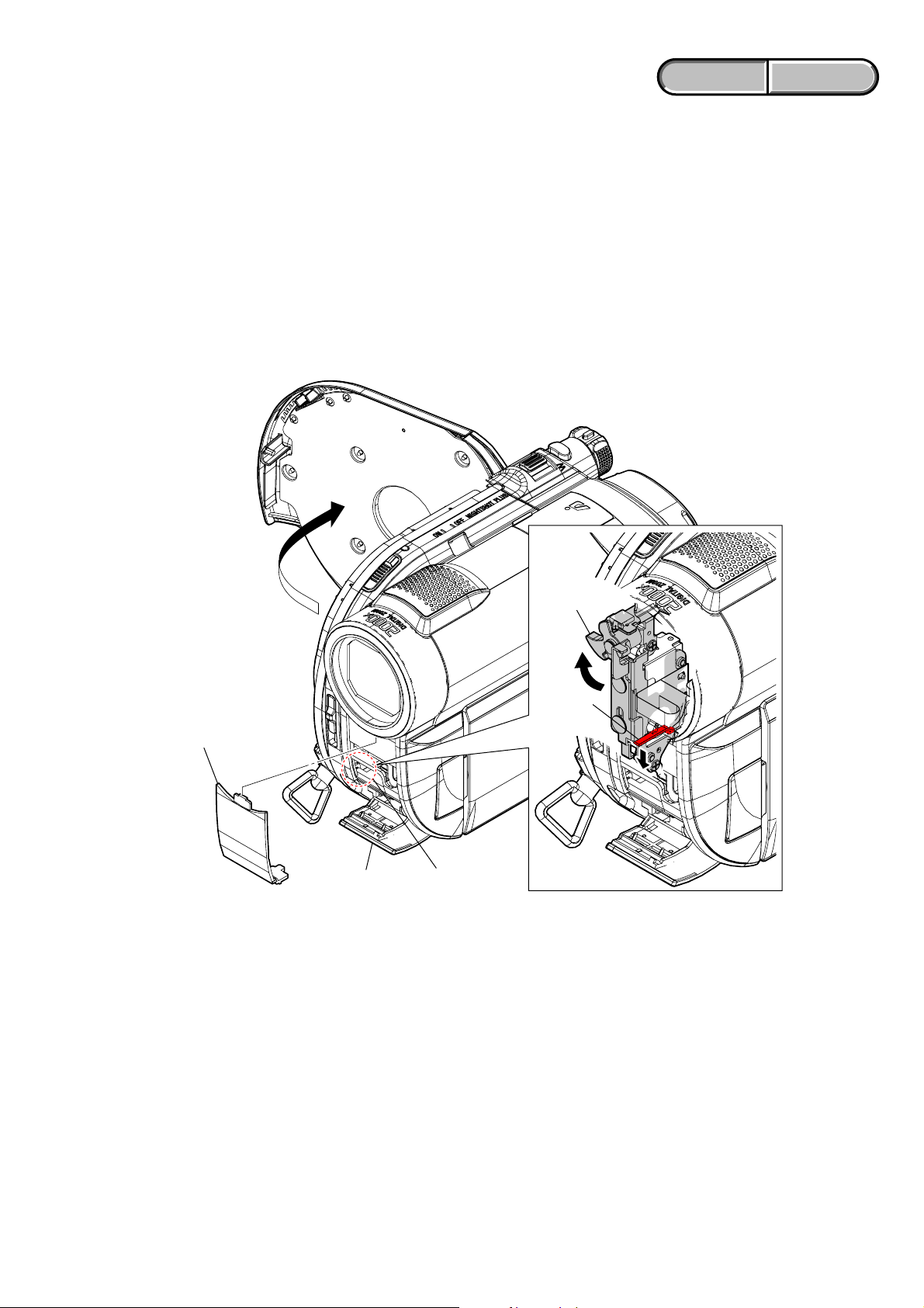
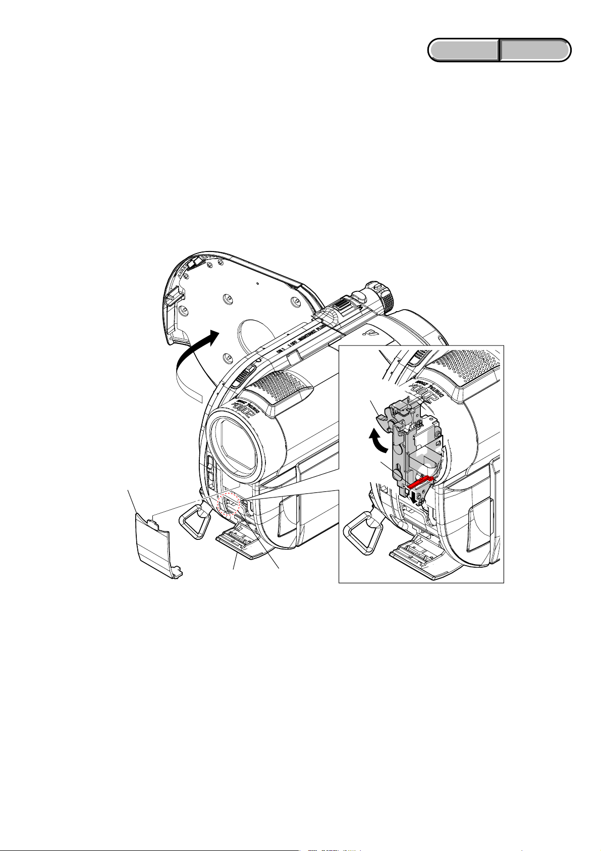
1-2. TO TAKE OUT A DISC WHEN NOT EJECT (FORCE EJECT)
1 Open the jack cover and remove the remote control window.
2 Insert the wire etc. in the hole and down the eject slider by it.
Charge Lever
Eject Slider
Remote Control Window
Jack Cover
Hole
1-3. PRECAUTION ON REPLACING THE VC-520 BOARD
DESTINATION DATA
When you replace to the repairing board, the written destination data of repairing board also might be changed to original setting.
Refer to Service Manual ADJ, and perform “DESTINATION DATA WRITE”.
USB SERIAL No.
The set is shipped with a unique ID (USB Serial No.) written in it.
This ID has not been written in a new board for service, and therefore it must be entered after the board replacement.
Refer to Service Manual ADJ, and perform “USB SERIAL No. INPUT”.
DCR-DVD110E/DVD115E/DVD310E/DVD410E/DVD610/
DVD610E/DVD710/DVD710E/DVD810/DVD810E_L2
1-1
ENGLISH JAPANESE
ENGLISH JAPANESE
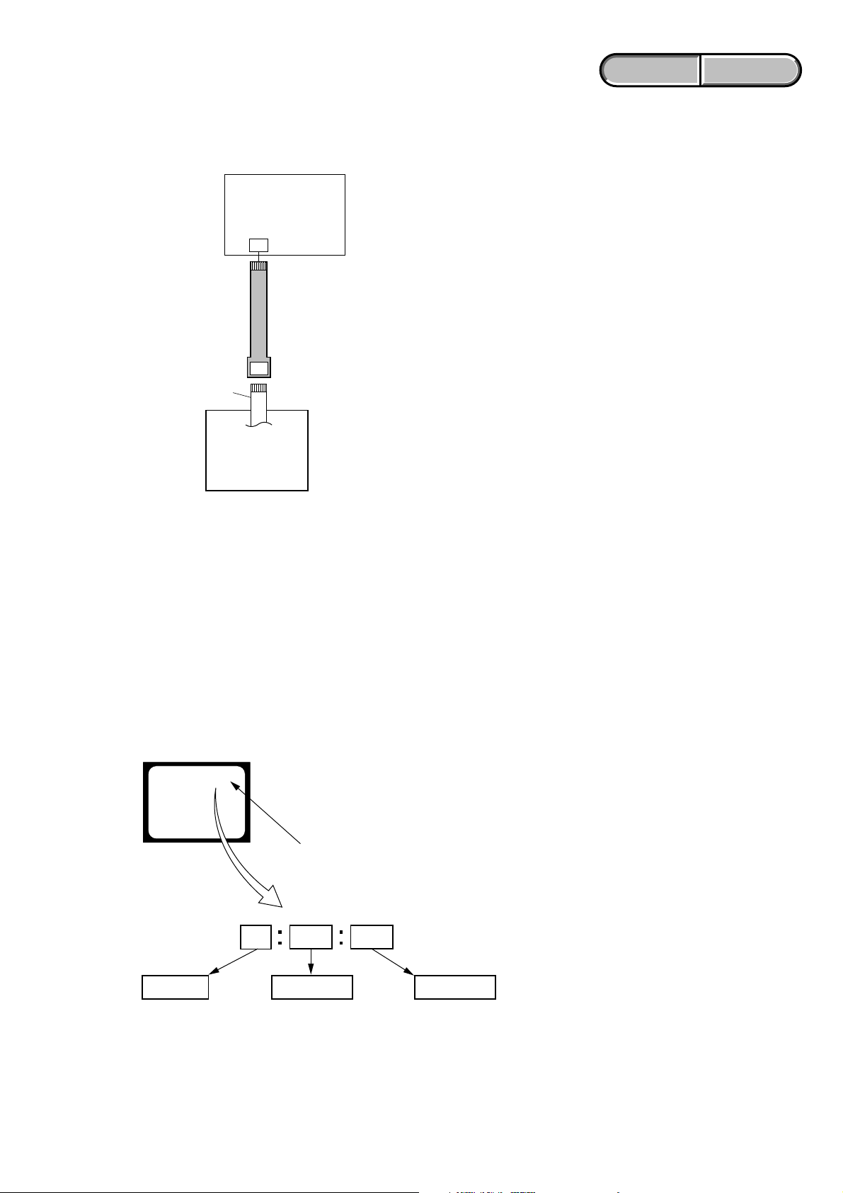
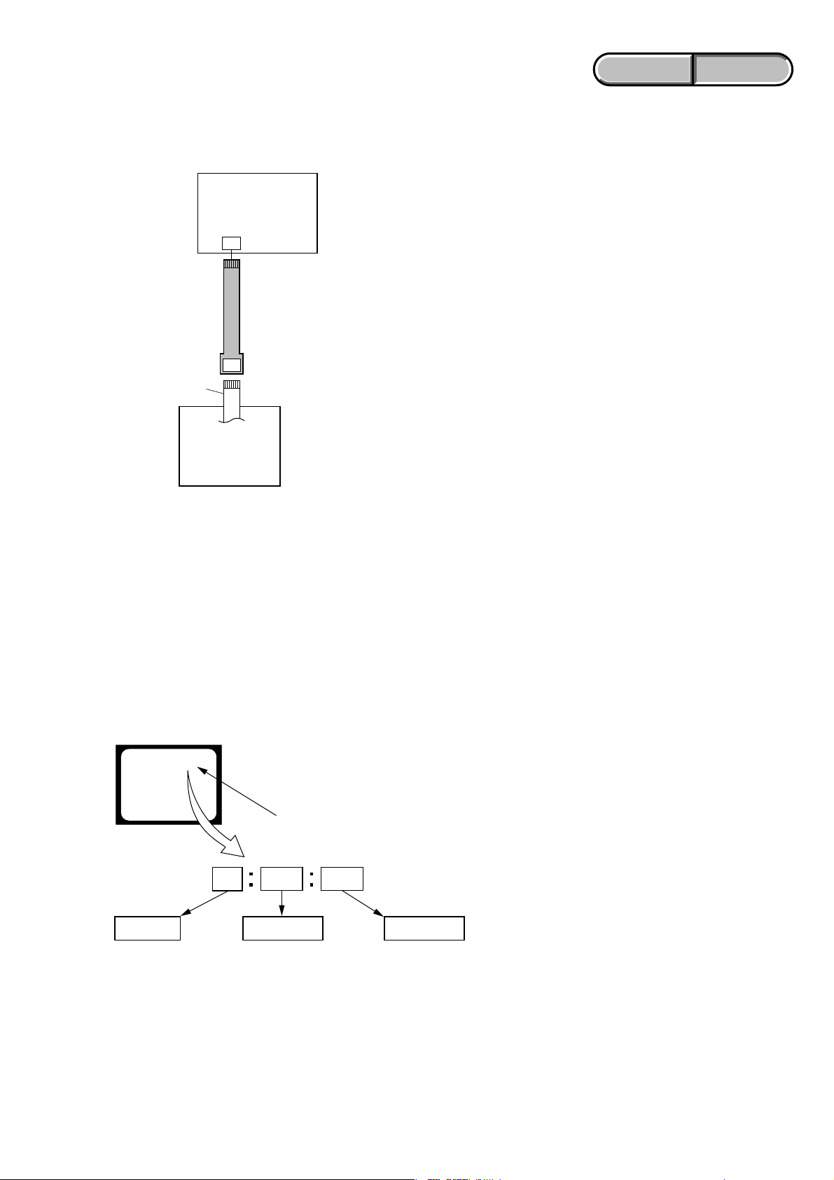
1-4. USING SERVICE JIG
Connect the extension cable (J-6082-572-A) between the DVD mechanism deck and CN4401 on the VC-520 board.
VC-520 board (side A)
CN4401
Extension cable (10P)
(J-6082-572-A)
Flexible board (10P)
DVD mechanism deck
1-5. SELF-DIAGNOSIS FUNCTION
1-5-1. Self-diagnosis Function
When problems occur while the unit is operating, the self-diagnosis
function starts working, and displays on the viewfinder or LCD
screen what to do.
Details of the self-diagnosis functions are provided in the Instruction
manual.
Viewfinder or LCD screen
C : 3 1 : 1 1
Blinks at 3.2 Hz
1-5-2. Self-diagnosis Display
When problems occur while the unit is operating, the counter of the
viewfinder or LCD screen shows a 4-digit display consisting of an
alphabet and numbers, which blinks at 3.2 Hz. This 5-character
display indicates the “repaired by:”, “block” in which the problem
occurred, and “detailed code” of the problem.
Repaired by:
C : Corrected by customer
H : Corrected by dealer
E : Corrected by service
engineer
DCR-DVD110E/DVD115E/DVD310E/DVD410E/DVD610/
DVD610E/DVD710/DVD710E/DVD810/DVD810E_L2
3 1C
Block
Indicates the appropriate
step to be taken.
E.g.
31 ....Reload the tape.
32 ....Turn on power again.
1 1
Detailed Code
Refer to “1-5-3. Self-diagnosis Code Table”.
1-2

1-5-3. Self-diagnosis Code Table
Self-diagnosis Code
ENGLISH JAPANESE
ENGLISH JAPANESE
Function
Repaired by:
C
C
C
E
E
E
E
E
E
E
E
E
Block
04
13
13
20
31
61
61
61
62
62
94
94
Detailed
Code
00
01
02
00
00
00
10
11
00
01
00
01
Symptom/State
Non-standard battery is used.
“Memory Stick Duo” is unformatted.
“Memory Stick Duo” is broken.
Disc access error
Flash memory data are rewritten.
Drive fault
Difficult to adjust focus
(Cannot initialize focus.)
Zoom operations fault
(Cannot initialize zoom lens.)
The abnormalities in initialization of
the focus lens and the abnormalities in
initialization of the zoom lens occurred
simultaneously.
Handshake correction function does not
work well. (With PITCH angular
velocity sensor output stopped.)
Handshake correction function does not
work well. (With YAW angular velocity
sensor output stopped.)
Fault of writing to or erasing the flash
memory
Internal flash memory fault
Correction
Use the InfoLITHIUM battery.
Format the “Memory Stick Duo”.
Insert a new “Memory Stick Duo”.
Clean the disc with the supplied cleaning cloth.
Use a compatible disc with the camcorder.
Make flash memory data correct value. (Note 1)
Inspect or replacement of the mechanism deck, IC (IC4401 on
the VC-520 board) and drive block.
Inspect the lens block focus reset sensor (pin 7 of CN5101 on
the VC-520 board) when focusing is performed when the focus
buttons of the touch panel are pressed in the focus manual mode,
and the focus motor drive circuit (IC5401 (Non MEGA model)
or IC5301 (MEGA model) on the VC-520 board) when the
focusing is not performed.
Inspect the lens block zoom reset sensor (pin qa of CN5101 on
the VC-520 board) when zooming is performed when the zoom
lever is operated, and the zoom motor drive circuit (IC5401 (Non
MEGA model) or IC5301 (MEGA model) on the VC-520 board)
when zooming is not performed.
Check whether the flexible board of the lens is broken, and
check whether it is inserted imperfectly. If there is no problem in
the flexible board, inspect the focus/zoom motor drive circuit
(IC5401 (Non MEGA model) or IC5301 (MEGA model) on the
VC-520 board).
Inspect PITCH angular velocity sensors (SE7002 on the CD672/CD-687 board) peripheral circuits. (MEGA model only)
Inspect YAW angular velocity sensors (SE7001 on the CD-672/
CD-687 board) peripheral circuits. (MEGA model only)
Inspect the flash memory (IC2101 on the VC-520 board). (Note 1)
Inspect the internal flash memory (MDL4060S3C) (DVD410E/
DVD810/DVD810E only)
Note 1: Refer to “1-3. DESTINATION DATA WRITE”, ADJ (9-852-249-51).
Note 2: Non MEGA model: DCR-DVD110E/DVD115E/DVD610/DVD610E
MEGA model: DCR-DVD310E/DVD410E/DVD710/DVD710E/DVD810/DVD810E
DCR-DVD110E/DVD115E/DVD310E/DVD410E/DVD610/
DVD610E/DVD710/DVD710E/DVD810/DVD810E_L2
1-3
ENGLISH JAPANESE
1. SERVICE NOTE
ENGLISH JAPANESE
1-1. 修理時の電源供給について
本機では,安定化電源(8.4Vdc)からバッテリ端子に電源を供給した場合,約10秒後にシャットオフし,動作しなくなります。
これを避けるため,下記の方法を用いてください。
方法:
DC入力端子を使用する。(ACアダプタ(AC-L200/L200B)を使用する。)
1-2. イジェクトしない時のディスク取出し方法(強制イジェクト)
1 ジャックカバーを開き,リモコン窓を外す。
2 穴に針金等を差し込み,イジェクトスライダを下げる。
チャージ
レバー
イジェクト
スライダ
リモコン窓
ジャックカバー
穴
1-3. VC-520基板交換時の注意
仕向けデータ
補修用基板と交換する時,補修用基板に書かれている仕向けデータは元の設定と違っている場合があります。
ADJ編を参照して,「DESTINATIONDATAWRITE」を行ってください。
USBシリアルNo.
セットは,1台毎に異なる固有のID(USBSerialNo.)を書き込んだ後,出荷されています。
新品の補修用基板には,このIDが書き込まれていないので,基板交換後にIDを入力する必要があります。
ADJ編を参照して,「USBSERIALNo.INPUT」を行ってください。
DCR-DVD110E/DVD115E/DVD310E/DVD410E/DVD610/
DVD610E/DVD710/DVD710E/DVD810/DVD810E_L2
1-4
1-4. 使用サービス治具
延長ケーブル(J-6082-572-A)をVC-520基板CN4401とDVDメカデッキの間に接続します。
VC-520基板(A面側)
CN4401
延長ケーブル(10P)
(J-6082-572-A)
フレキシブル基板(10P)
ENGLISH JAPANESE
ENGLISH JAPANESE
DVDメカデッキ
1-5. 自己診断機能
1-5-1. 自己診断機能について
本機の動作に不具合が生じたとき,自己診断機能が働き,
ビューファインダまたはL C D 画面に,どう処置したらよい
か判断できる表示を行います。自己診断機能については取扱
説明書にも掲載されています。
ビューファインダまたはLCD画面
C : 3 1 : 1 1
3.2Hz点滅
3 1C
1 1
1-5-2. 自己診断表示
本機の動作に不具合が生じたとき,ビューファインダまたは
LCD画面のカウンタ表示部分がアルファベットと数字の4桁
表示になり,3.2H z で点滅します。この5 文字の表示によっ
て対応者分類および不具合の生じたブロックの分類,不具合
の詳細コードを示します。
対応者分類
C :お客さま自身で対応
H :販売店で対応
E :サービスエンジニア
で対応
DCR-DVD110E/DVD115E/DVD310E/DVD410E/DVD610/
DVD610E/DVD710/DVD710E/DVD810/DVD810E_L2
対応方法の違いにより分類
例 31 ・・・テープを入れ直す
32 ・・・電源を入れ直す
ブロック分類
詳細コード
「1-5-3.自己診断コード表」
を参照
1-5

1-5-3. 自己診断コード表
自己診断コード
対
応
者
C
C
C
E
E
E
E
E
E
E
E
E
ブロック
機能
04
13
13
20
31
61
61
61
62
62
94
94
詳細
コード
00
01
02
00
00
00
10
11
00
01
00
01
症状/状態
標準以外のバッテリを使用している
フォーマットしていないメモリー
ステックデュオを入れた
メモリーステックデュオが壊
れている
ディスクアクセスエラー
フラッシュメモリが書き換えられて
いる
ドライブ不良
フォーカスが合いにくい
(フォーカスの初期化ができない)
ズーム動作の異常(ズームレンズの
初期化ができない)
フォーカス,ズーム異常
手振れ補正が効きにくい(PITCH
角速度センサ出力張り付き)
手振れ補正が効きにくい(YAW角
速度センサ出力張り付き)
フラッシュメモリの書込み/消去動
作不良
内蔵フラッシュメモリ不良
ENGLISH JAPANESE
ENGLISH JAPANESE
対応/方法
インフォリチウムバッテリを使用する。
メモリーステックデュオをフォーマットする。
新しいメモリーステックデュオに交換する。
ディスククリーニングをする。または本機に対応したディ
スクに交換する。
フラッシュメモリのデータを元の値に戻す(注)
メカデッキ駆動IC(VC-520基板IC4401)周辺回路および
駆動部分を点検または交換する。
タッチパネルでフォーカス操作をしたときにフォーカス動
作をすれば,レンズブロックのフォーカスリセットセンサ
(VC-520基板CN51017ピン)を点検する。フォーカス動
作をしなければフォーカスモータ駆動回路(VC-520基板
IC5301)を点検する。
ズームレバーを操作したときにズーム動作をすれば,レン
ズブロックのズームリセットセンサ(VC-520基板CN5101
qaピン)を点検する。ズーム動作をしなければズームモー
タ駆動回路(VC-520基板IC5301)を点検する。
フレキ切れ,半差し等の点検を行う。問題がない場合は
フォーカス/ズームモータ駆動IC(VC-520基板IC5301)周
辺回路を点検する。
PITCH角速度センサ(CD-672/CD-687基板SE7002)周辺回
路を点検する。
YAW角速度センサ(CD-672/CD-687基板SE7001)周辺回
路を点検する。
フラッシュメモリ(VC-520基板IC2101)を点検する。
(注)
内蔵フラッシュメモリ(MDL4060S3C)を点検する。
注:調整編(9-852-249-51)「1-3.DESTINATIONDATAWRITE」を参照してください。
DCR-DVD110E/DVD115E/DVD310E/DVD410E/DVD610/
DVD610E/DVD710/DVD710E/DVD810/DVD810E_L2
1-6E

2. DISASSEMBLY
Cut and remove the part of gilt
which comes off at the point.
(Be careful or some
pieces of gilt may be left inside)
NOTE FOR REPAIR
• Make sure that the flat cable and flexible board are not cracked of bent at the terminal.
Do not insert the cable insufficiently nor crookedly.
• When remove a connector, don’t pull at wire of connector. It is possible that a wire is snapped.
• When installing a connector, don’t press down at wire of connector.
It is possible that a wire is snapped.
DCR-DVD110E/DVD115E/DVD310E/DVD410E/DVD610/
DVD610E/DVD710/DVD710E/DVD810/DVD810E_L2
2-1
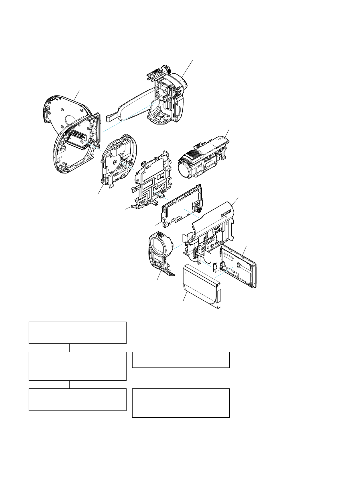
2-1. IDENTIFYING PARTS
Cabinet L
⋅ FP-569 Flexible Board
Mechanism Deck
Main Frame
VC-520 Board
BT/EVF Block
⋅ BL-021 Board
⋅ BL-022 Board
⋅ FP-839 Flexible Board
⋅ FP-841 Flexible Board
Lens Block
⋅ CD-672 Board
⋅ CD-687 Board
⋅ CD-731 Board
⋅ FP-838 Flexible Board
⋅ FP-840 Flexible Board
Cabinet R
⋅ CK-191 Board
⋅ CK-192 Board
⋅ FP-573 Flexible Board
⋅ FP-842 Flexible Board
⋅ MS-391 Board
⋅ MS-392 Board
LCD Block
⋅ PD-351 Board
⋅ PD-352 Board
⋅ RV-011 Board
⋅ RV-012 Board
- DISASSEMBLY FLOW -
2-2-1. OVERALL SECTION
⋅ Cabinet R
⋅ BT/EVF Block
2-2-2. CABINET R SECTION-1
⋅ Front Panel
⋅ MS-391/392 Board
⋅ LCD Block
2-2-3. CABINET R SECTION-2
⋅ Hinge Block
⋅ CK-191/192 Board
Front Panel
P Cabinet
2-2-4. CABINET L SECTION
⋅ Cabinet L
2-2-5. MD Section
⋅ Lens Block
⋅ VC-520 Board
⋅ Mechanism Deck
DCR-DVD110E/DVD115E/DVD310E/DVD410E/DVD610/
DVD610E/DVD710/DVD710E/DVD810/DVD810E_L2
2-2
HELP
EXPLODED VIEW
DVD410E/DVD810/
DVD810E
1-2 (#2)
1-8 (#2)
1-16 (#2)
1-9 (#2)
1-10 (#2)
1-3 (Claw)
1-1 (Open)
1-11 (Open)
1-15 (Open)
1-4
(Claw)
1-12
(Claw)
1-13
(Claw)
1-14
1-17
1-18
1-5
1-6
1-7
1Cabinet R
(See Page 2-4)
2BT/EVF Block
2-1
2-3 (#2)
2-4
(#3)
2-5 (#3)
2-7
2-8
2-6 (#11)
2-2
Cabinet L
Section
(See Page 2-6)
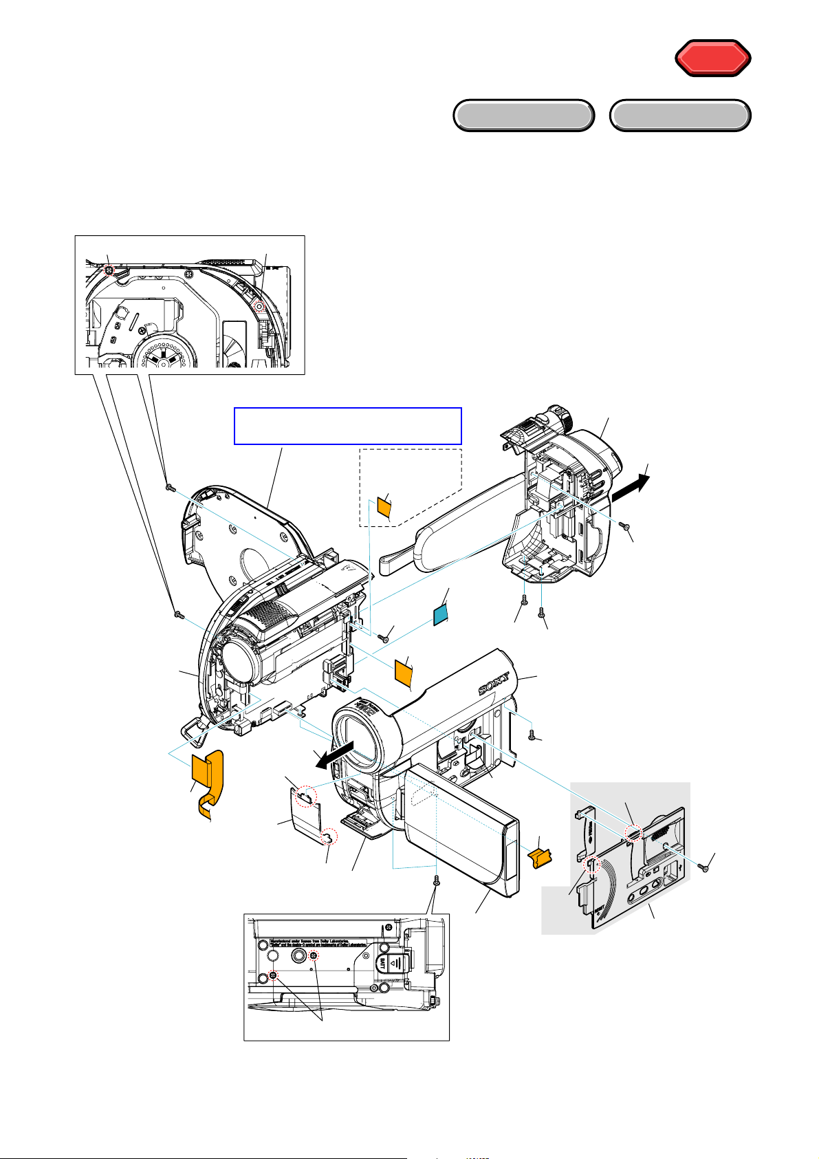
Refer to page 1-1 “1-2. To take out
a disc when not eject (force eject)".
HELP
2-2. DISASSEMBLY
2-2-1. OVERALL SECTION
Follow the disassembly in the numerical order given.
1 Cabinet R (1-1 to 1-18)
2 BT/EVF Block (2-1 to 2-8)
HARDWARE LIST
DCR-DVD110E/DVD115E/DVD310E/DVD410E/DVD610/
DVD610E/DVD710/DVD710E/DVD810/DVD810E_L2
2-3
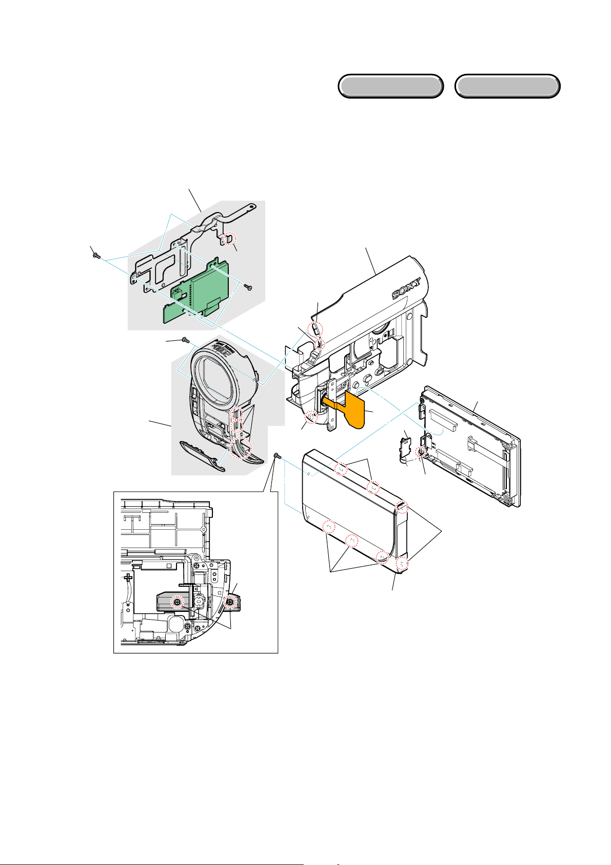
2-2-2. CABINET R SECTION-1
EXPLODED VIEW
Follow the disassembly in the numerical order given.
1 Front Panel (1-1 to 1-5)
2 MS-391/392 Board (2-1 to 2-2)
3 LCD Block (3-1 to 3-9)
2MS-391/392 Board
HARDWARE LIST
2-1 (#11)
1-1 (#11)
1Front Panel
2-2
(Claw)
1-4
(Claw)
1-2
(Claw)
1-3
(Boss)
1-5 (Claw)
Cabinet R Section-2
(See Page 2-5)
3LCD Block
3-7
3-8
3-3
(Claw)
3-9
(Claw)
DCR-DVD110E/DVD115E/DVD310E/DVD410E/DVD610/
DVD610E/DVD710/DVD710E/DVD810/DVD810E_L2
3-1
(Rotate)
3-2 (#2)
2-4
3-4
(Claw)
3-5
(Claw)
3-6
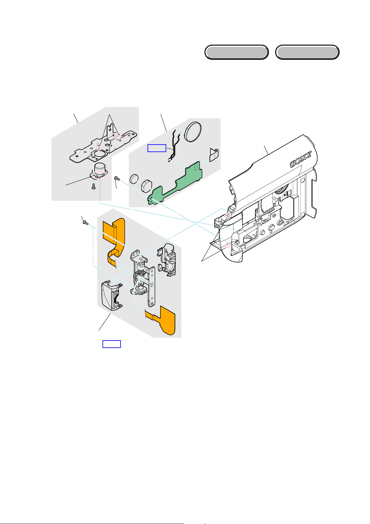
2-2-3. CABINET R SECTION-2
EXPLODED VIEW
Follow the disassembly in the numerical order given.
1 Hinge Block (1-1 to 1-2)
2 CK-191/192 Board (2-1 to 2-5)
HARDWARE LIST
2-3
2-2
(Tripod Screw Ledge)
1-1 (#11)
2-1 (Boss)
2-4
(#11)
2CK-191/192 Board
2-5
HELP 2
1-2 (Boss)
DCR-DVD110E/DVD115E/DVD310E/DVD410E/DVD610/
DVD610E/DVD710/DVD710E/DVD810/DVD810E_L2
1Hinge Block
HELP 1
2-5
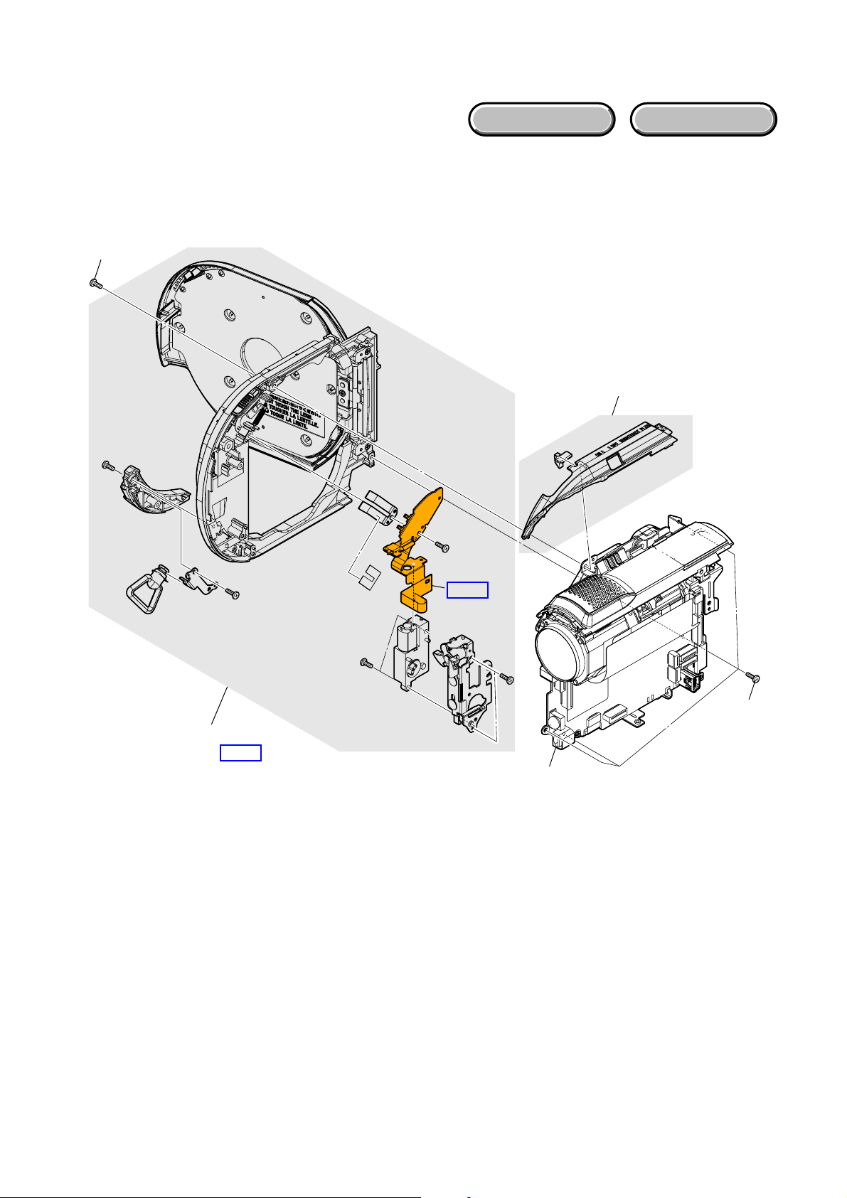
2-2-4. CABINET L SECTION
EXPLODED VIEW
Follow the disassembly in the numerical order given.
1 Cabinet L (1-1 to 1-3)
1-1 (#11)
HARDWARE LIST
1-2
1Cabinet L
HELP 3
HELP 4
1-3
(#11)
MD Section
(See Page 2-7)
DCR-DVD110E/DVD115E/DVD310E/DVD410E/DVD610/
DVD610E/DVD710/DVD710E/DVD810/DVD810E_L2
2-6
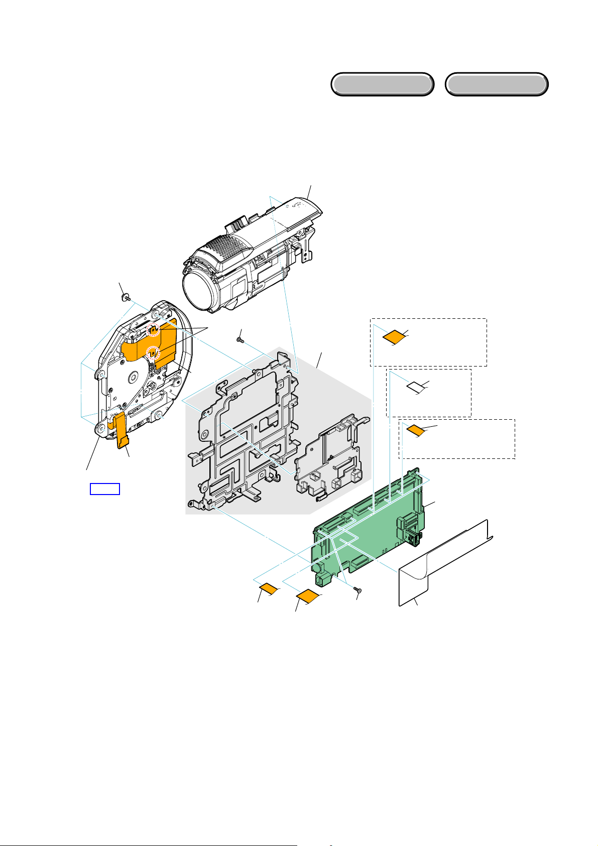
EXPLODED VIEW
2-2-5. MD SECTION
Follow the disassembly in the numerical order given.
1 Lens Block (1-1 to 1-7)
2 VC-520 Board (2-1 to 2-3)
3 Mechanism Deck (3-1 to 3-3)
3-1 (#16)
HARDWARE LIST
1Lens Block
2-3
3Mechanism Deck
HELP 5
2-2
3-2
1-7 (#3)
1-3
1-2
3-3
1-4
DVD310E/DVD410E/DVD710/
DVD710E/DVD810/DVD810E
DVD110E/DVD115E/
DVD610/DVD610E
DVD310E/DVD410E/DVD710/
DVD710E/DVD810/DVD810E
-520
VC
2-1 (#3)
1-1
1-5
1-6
2VC-520 Board
DCR-DVD110E/DVD115E/DVD310E/DVD410E/DVD610/
DVD610E/DVD710/DVD710E/DVD810/DVD810E_L2
2-7E
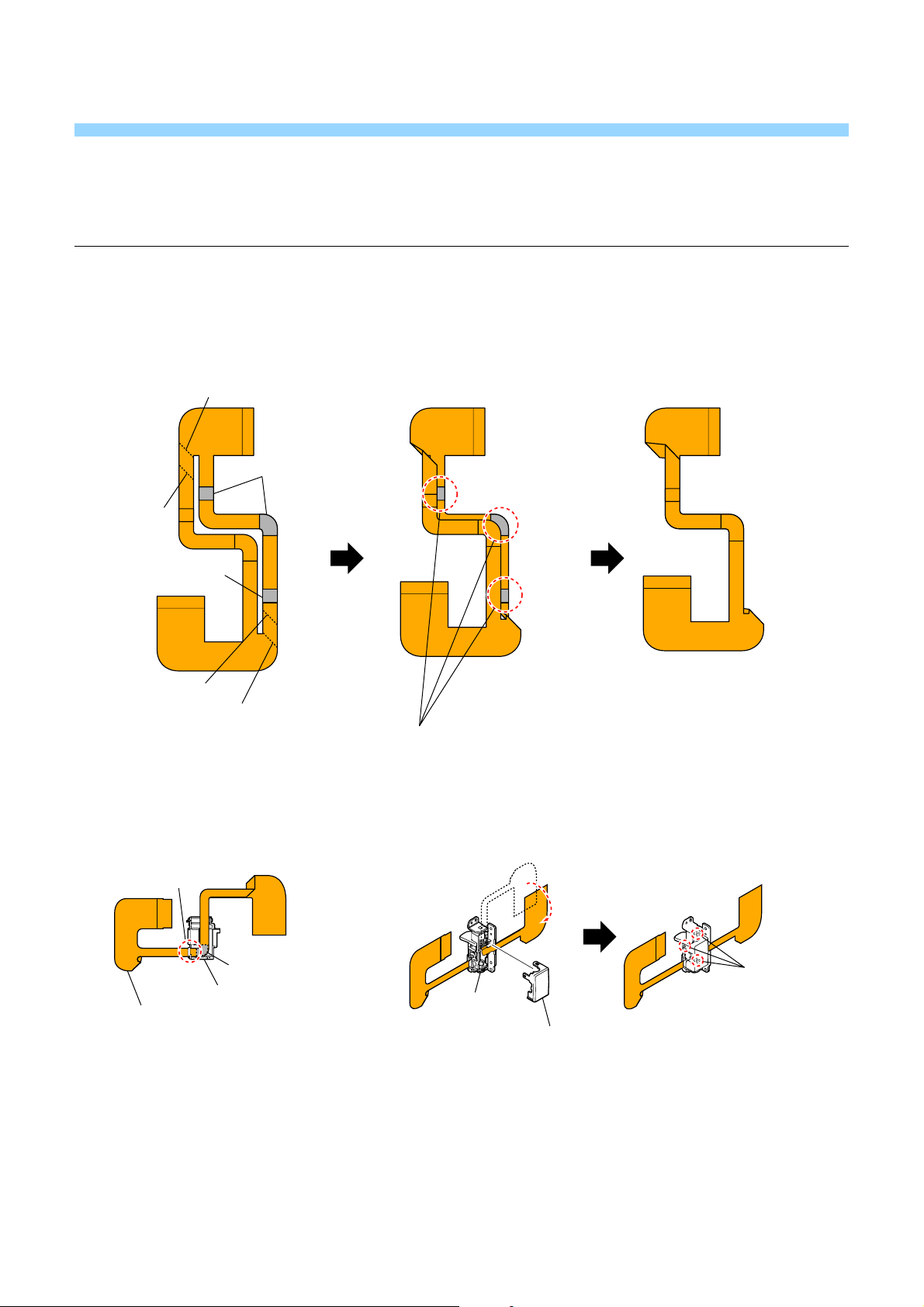
HELP
Sheet attachment positions and procedures of processing the flexible boards/harnesses are shown.
HELP 1: THE METHOD OF ATTACHMENT OF FP-573 FLEXIBLE BOARD
1 Fold dotted line parts of the FP-573 flexible board
as shown in figure.
Valley fold
Adhesive tape
Mountain
fold
Adhesive tape
Valley fold
Mountain fold
2 Install FP-573 flexible board
Hinge Cover (M).
in the
Claw
Adhesive tape
Hinge Cover (M)
FP-573
Stick it together in the adhesive tape
while bending the FP-573 flexible board.
3 Install the Hinge Cover (C).
Claw
Hinge Assy
Hinge Cover (C)
DCR-DVD110E/DVD115E/DVD310E/DVD410E/DVD610/
DVD610E/DVD710/DVD710E/DVD810/DVD810E_L2
HELP
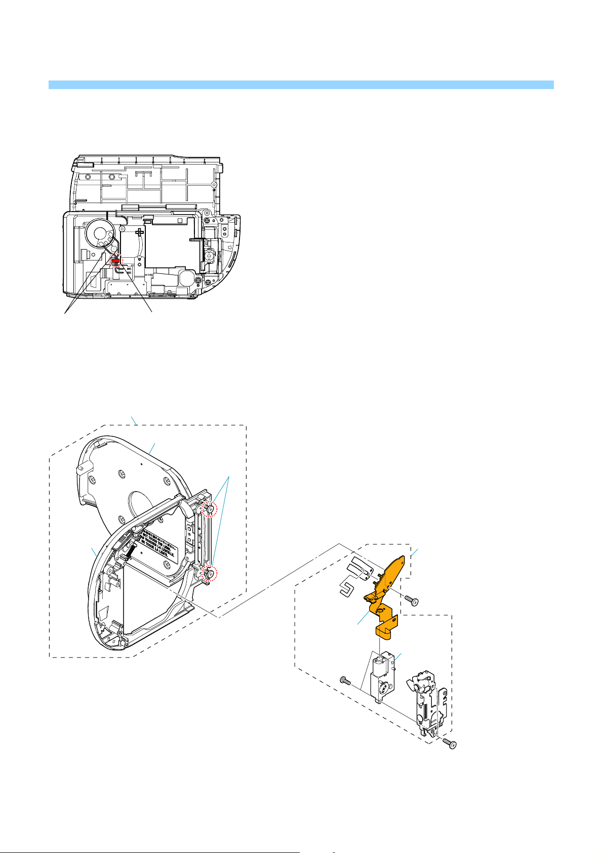
HELP 2: SPEAKER HARNESS
Speaker Harness Claw
HELP 3: PRECAUTION WHEN INSTALLING THE CABINET L ASSY FOR SERVICE
Cabinet L assy for service
Cabinet D
block
D lid block
Screws
When the eject block is installed on the cabinet L assy
for service, a discrepancy could be made between the
cabinet D block and the D lid block, and as a result,
the D lid may not to be closed.
In case of such discrepancy, loosen the screws on the
hinge to eliminate the discrepancy of the D lid block,
and then retighten the screws.
Eject block
FP-569 flexible
complete board
M903
DCR-DVD110E/DVD115E/DVD310E/DVD410E/DVD610/
DVD610E/DVD710/DVD710E/DVD810/DVD810E_L2
HELP
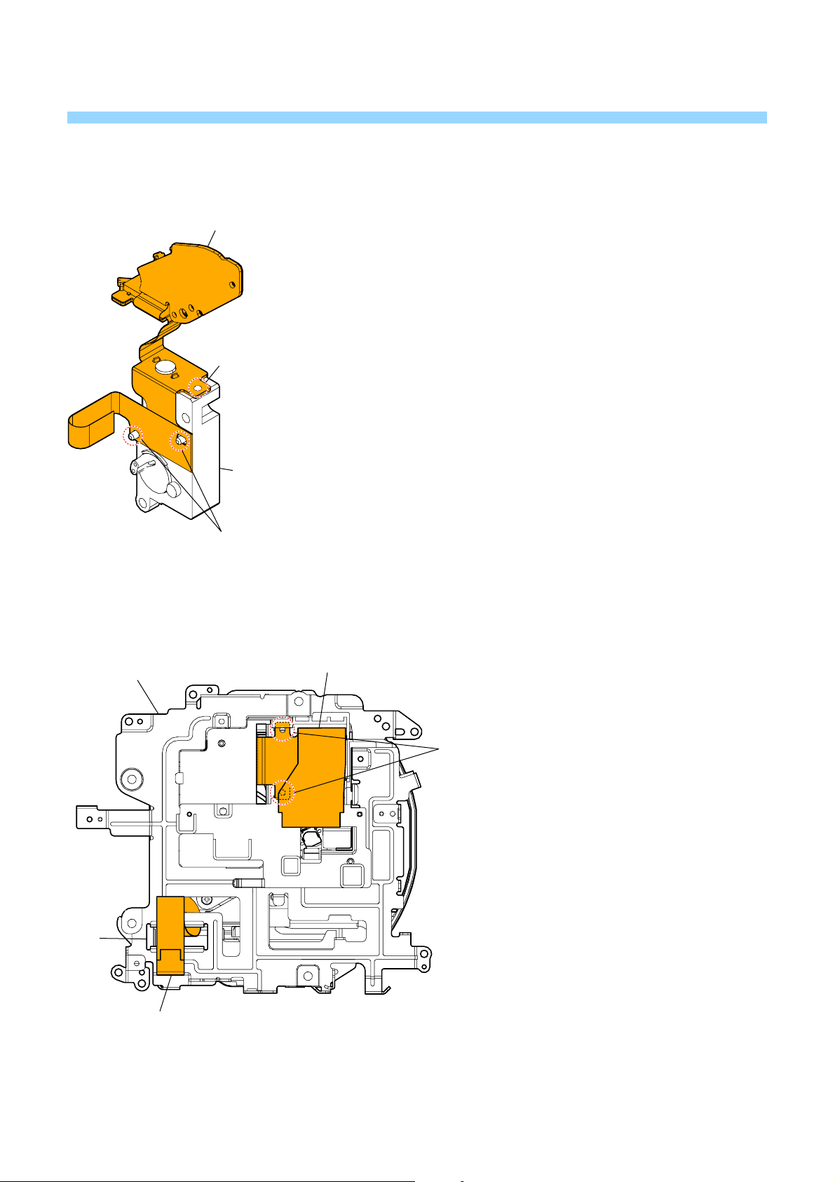
HELP 4: FP-569 FLEXIBLE BOARD
FP-569 Flexible Board
Boss
Motor Unit
Boss
HELP 5: MECHANISM DECK FLEXIBLE BOARD
MD Frame
Hole
Mechanism Deck Flexible Board
Mechanism Deck Flexible Board
Hook
DCR-DVD110E/DVD115E/DVD310E/DVD410E/DVD610/
DVD610E/DVD710/DVD710E/DVD810/DVD810E_L2
HELP

Link
Link
3. BLOCK DIAGRAMS
OVERALL BLOCK DIAGRAM (1/6)
OVERALL BLOCK DIAGRAM (2/6)
OVERALL BLOCK DIAGRAM (3/6)
OVERALL BLOCK DIAGRAM (4/6)
OVERALL BLOCK DIAGRAM (5/6)
OVERALL BLOCK DIAGRAM (6/6)
POWER BLOCK DIAGRAM (1/3)
POWER BLOCK DIAGRAM (2/3)
POWER BLOCK DIAGRAM (3/3)
DCR-DVD110E/DVD115E/DVD310E/DVD410E/DVD610/
DVD610E/DVD710/DVD710E/DVD810/DVD810E_L2
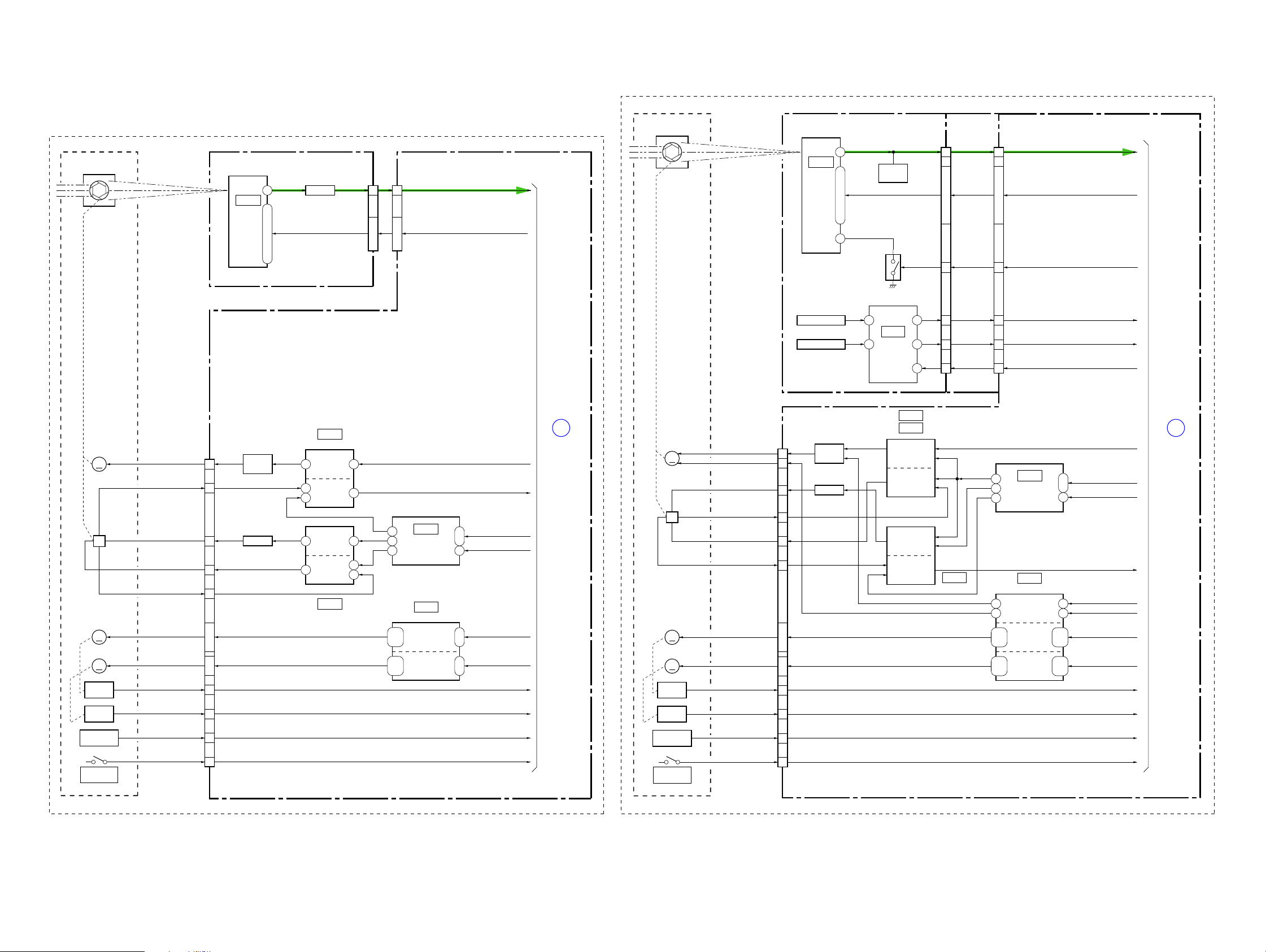
3. BLOCK DIAGRAMS
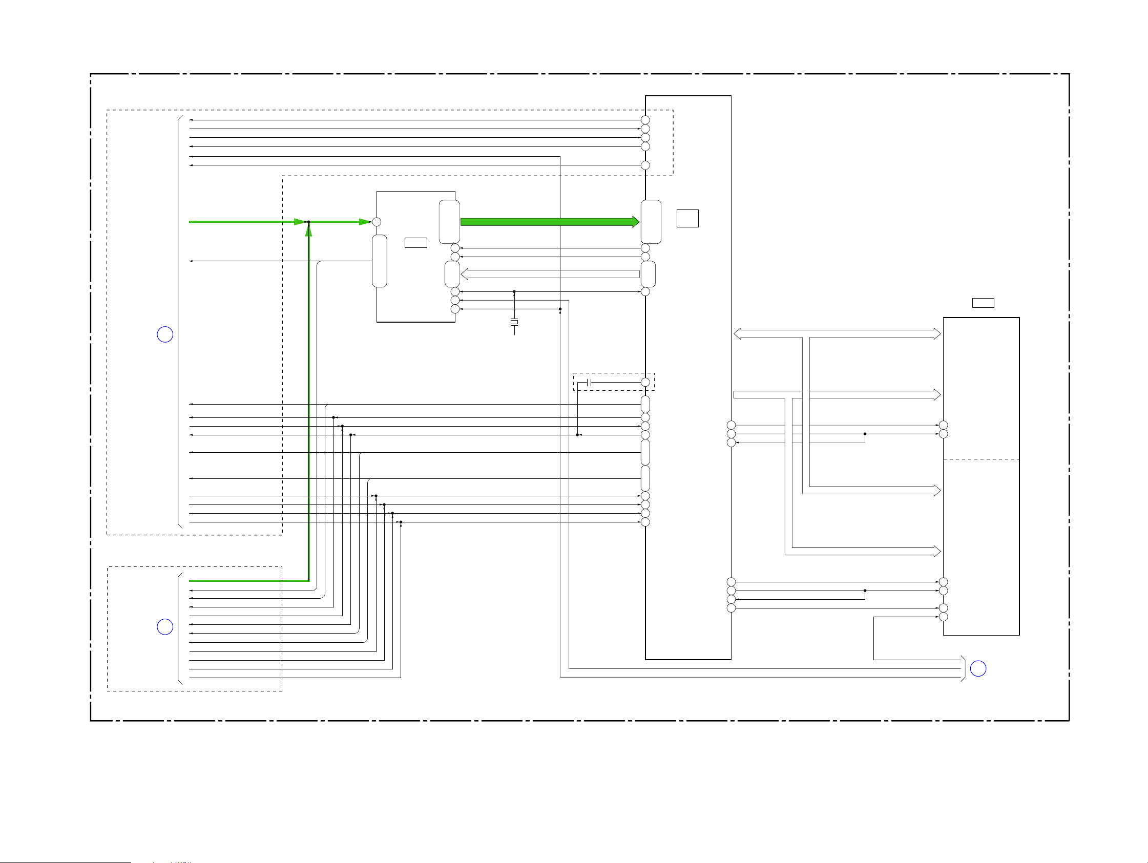
3-1. OVERALL BLOCK DIAGRAM (1/6) ( ) : Number in parenthesis ( ) indicates the division number of schematic diagram where the component is located.
MEGA model
LENS BLOCK
Non MEGA model
LENS BLOCK
IRIS
(SHUTTER)
CD-731 BOARD
8
IC7101
CCD
IMAGER
VC-520 BOARD (1/7)
15
3 - 10, 12, 13
CN1203
2
14 - 7, 5, 4
CCD_OUT+CCD_OUT
Q7101
BUFFER
V1 - V6, RG, VSHT, H1, H2 V1 - V6, RG, VSHT, H1, H2
1 - 6, 10, 12, 14, 15
CN7101
IRIS
(SHUTTER)
CD-672/CD-687 BOARD FP-838
IC7002
CCD
IMAGER
12
Q7002
CLAMP
V1 - V6, RG, H1, H2, SUB V1 - V6, RG, H1, H2, SUB
7 - 2, 14, 18, 16, 19
1
Q7001
CN7001
RCSUB
FLEXIBLE
BOARD
27
6, 9 - 14, 17, 19, 21
7
VC-520 BOARD (2/7)
CN1201
2
23, 20 - 15, 12, 10, 8
22
CCD_OUT+
CSUB
IRIS
METER
M
H
FOCUS
MOTOR
M
ZOOM
MOTOR
M
FOCUS
SENSOR
ZOOM
SENSOR
LENS TEMP
SENSOR
NIGHTSHOT
PLUS
I_DRIVE (-)
I_HALL (-)
I_BIAS (-)
I_BIAS (+)
I_HALL (+)
FC_XA, FC_A,
FC_XB, FC_B
ZM_A, ZM_XA,
ZM_XB, ZM_B
FC_SENS_OUT
ZM_SENS_OUT
THERMO_OUT
IR_SWITCH_OUT
SE7002
PITCH SENSOR
SE7001
YAW SENSOR
IC5102
IRIS DRIVE
5
HALL AMP
6
7
HALL GAIN
1
HALL BIAS
(2/20)
IC5103
(2/20)
31
7
IC5101
1
5
3
2
EVR
2
(D/A CONVERTER)
3
(2/20)
IC5401
(3/20)
FOCUS
MOTOR
21, 4
23, 2,
DRIVE
ZOOM
MOTOR
17, 7
5, 19,
DRIVE
8
IRIS_PWM
I_HALL_AD
CAM_SO, CAM_SCK
6, 7
13 - 16 9 - 12
DA_STRB
EN0, DIR0A, DIR0B
EN01, DIR1A, DIR1B
FC_RST
ZM_RST
LENS_TEMP_AD
XNS_SW
Q5401
CN5101
13
18
17
15
16
21 - 241 - 4
7
11
6
19
05
IRIS
DRIVE
Q5102
AMP
1
OVERALL (2/6)
(PAGE 3-2)
IRIS
METER
M
H
FOCUS
MOTOR
M
ZOOM
MOTOR
M
FOCUS
SENSOR
ZOOM
SENSOR
LENS TEMP
SENSOR
NIGHTSHOT
PLUS
IRIS_DRIVE (-)
IRIS_DRIVE (+)
IRIS_BIAS (-)
IRIS_HALL (-)
IRIS_BIAS (+)
IRIS_HALL (+)
FOCUS_XA, FOCUS_A,
FOCUS_XB, FOCUS_B
ZOOM_A, ZOOM_XA,
ZOOM_XB, ZOOM_B
FC_SENSE_OUT
ZM_SENSE_OUT
TEMP_OUT
IR_SWITCH_OUT
14
13
17
18
15
16
7
11
6
19
CN5101
21 - 241 - 4
Q5301
IRIS
DRIVE
Q5102
AMP
8
PITCH/YAW
12
IC7003
SENSOR
AMP
IRIS DRIVE
HALL BIAS
HALL GAIN
HALL AMP
IC5102
IC5302
2
4
18
2
19
3
(2/20)
(4/20)
IC5103
(2/20)
25
27
26
IC5101
3
2
(D/A CONVERTER)
1
(2/20)
IC5301
(4/20)
F3
IRIS DRIVE
F4
FOCUS
MOTOR
D2, B1
F2, E2,
DRIVE
ZOOM
MOTOR
E6, D6
C6, B7,
DRIVE
EVR
6, 7
8
E4
G1
D3, E3
F5, G6,
A6, C5
D5, B6,
PITCH_AD
YAW_AD
VST_C_RESET
IRIS_PWM
CAM_SO, CAM_SCK
DA_STRB
I_HALL_AD
CAM_DD_ON
SHUTTER_ON
EN0, DIR0A, DIR0B
EN01, DIR1A, DIR1B
FC_RST
ZM_RST
LENS_TEMP_AD
XNS_SW
2
OVERALL (2/6)
(PAGE 3-2)
Non MEGA model: DCR-DVD110E/DVD115E/DVD610/DVD610E
MEGA model: DCR-DVD310E/DVD410E/DVD710/DVD710E/DVD810/DVD810E
DCR-DVD110E/DVD115E/DVD310E/DVD410E/DVD610/
DVD610E/DVD710/DVD710E/DVD810/DVD810E_L2
A : VIDEO SIGNAL
3-1
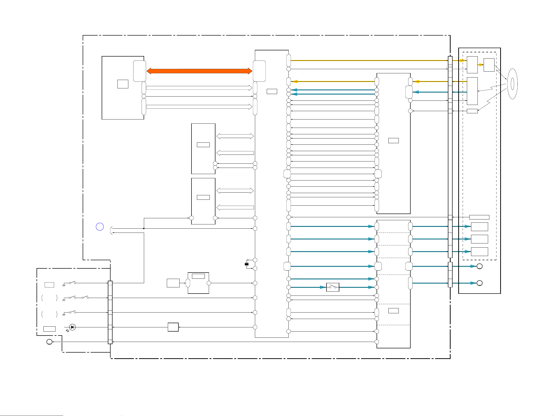
3-2. OVERALL BLOCK DIAGRAM (2/6)
( ) : Number in parenthesis ( ) indicates the division number of schematic diagram where the component is located.
VC-520 BOARD (3/7)
MEGA model
OVERALL (1/6)
(PAGE 3-1)
A : VIDEO SIGNAL
CSUB
PITCH_AD
YAW_AD
VST_C_RESET
CAM_DD_ON
SHUTTER_ON
CCD_OUT+
V1 - V6, RG, H1, H2, SUB
2
K4
IC1201
A/D CONVERTER,
TIMING
GENERATOR
(1/20)
C8, C1, B7, B1, A1
H10, G8, F8, E8, C9,
AD2 - AD13
B8 - B10, C7,
E10, F9, F10, G9
C10, D8, D9, E9,
TG_VD
C4
TG_HD
C5
CH_CS, CH_SI, CH_SO, CH_SCK
J10, J6
K9, H9,
CHCK
A8
XSYS_RST
B6
CAM_DD_ON
H2
24MHz: Non MEGA model
33MHz: MEGA model (NTSC)
27MHz: MEGA model (PAL)
X1201
CSUB
PITCH_AD
YAW_AD
VST_C_RESET
SHUTTER_ON
R4
AK33
AL34
H21
F4
(5/20 - 7/20)
C13, D11, B12, B11
A14, C14, D12, A13,
D13, C12, A12, B13,
B10
D10
K16, L16
L17, M17,
D9
IC1701
(1/5)
CPU
EMC_DATA [0] EMC_DATA [31]
IC2101
(8/20)
EMC_DATA [0] - EMC_DATA [31]
Non MEGA model
CAM_SO, CAM_SCK
DA_STRB
I_HALL_AD
IRIS_PWM
EN0, DIR0A, DIR0B
EN01, DIR1A, DIR1B
FC_RST
ZM_RST
LENS_TEMP_AD
XNS_SW
IRIS_COM
CAM_SO, CAM_SCK
DA_STRB
I_HALL_AD
IRIS_PWM
EN0, DIR0A, DIR0B
EN01, DIR1A, DIR1B
FC_RST
ZM_RST
LENS_TEMP_AD
XNS_SW
W2
K17, J17
G10
AK34
W1
M7, N7, K8
L8, L9, J8
AE32
A5
AL35
C6
EMC_ADDR [0] EMC_ADDR [15]
AF10
W25
EMC_CLK0_IN
W26
EMC_ADDR [0] - EMC_ADDR [12],
EMC_ADDR [14], EMC_ADDR [15]
EMC_XCS [1]
EMC_CLK0_OUT
EMC_DATA [0] - EMC_DATA [15]
512M SDRAM
J13
K11
512M OneNAND FLASH
Non MEGA model
OVERALL (1/6)
(PAGE 3-1)
05
Non MEGA model: DCR-DVD110E/DVD115E/DVD610/DVD610E
MEGA model: DCR-DVD310E/DVD410E/DVD710/DVD710E/DVD810/DVD810E
DCR-DVD110E/DVD115E/DVD310E/DVD410E/DVD610/
DVD610E/DVD710/DVD710E/DVD810/DVD810E_L2
1
CCD_OUT+
V1 - V6, RG, VHST, H1, H2
CAM_SO, CAM_SCK
DA_STRB
I_HALL_AD
IRIS_PWM
EN0, DIR0A, DIR0B
EN01, DIR1A, DIR1B
FC_RST
ZM_RST
LENS_TEMP_AD
XNS_SW
XSYS_RST
CAM_DD_ON
3-2
AG10
Y25
EMC_CLK1_OUT
Y26
AF16
EMC_ADDR [0] - EMC_ADDR [15]
EMC_XCS [0]
EMC_CLK1_OUT
EMC_XRESET_OUT
XFLASH_RST
U3
T4
P11
E8
XFLASH_RST
XSYS_RST
CAM_DD_ON
3
OVERALL (6/6)
(PAGE 3-6)
3-3. OVERALL BLOCK DIAGRAM (3/6)
( ) : Number in parenthesis ( ) indicates the division number of schematic diagram where the component is located.
FP-569 FLEXIBLE BOARD
S5691
OPEN
LID OPEN
DETECT
S5693 S5692
VC-520 BOARD (4/7)
(5/20 - 7/20)
4
OVERALL (6/6)
(PAGE 3-6)
XEJECT_SW
LID_OPEN
CN4402
5
6
IC1701
(2/5)
CPU
XEJECT_SW
AJ8, AJ10, AM12, AJ9
AH11, AJ11, AJ13, AH9,
AJ14, AH8, AH13, AH10,
AH12, AH14, AJ12, AN12,
AM9 - AM11
TXD_TO_IC_4201, RXD_TO_IC_4201, XSCK_IC_4201, XCS_IC_4201
G19, H18, G18, H19
XIC_4201_RESET_A
SE4501
SHOCK
SENSOR
ATA_D0 - ATA_D15
ATA_A0 - ATA_A2
XATA_RESET
IC4303
64M SDRAM
(10/20)
IC4302
16M FLASH
(10/20)
B4
IC4501
SHOCK
SENSOR
2, 3
AMP
(18/20)
DVD MECHANISM DECK
(DDX-C2000)
LDD_W1DIS - LDD_W3DISWP1_OP - WP3_OP
Y5, AB5, AA5
Y12
P20, P21, P23, R22,
L22, L20, M22, N21,
R21, P22, N20, N22,
M21, M20, L21, R20
IC4201
H21, J21, H22
R23AL4
DVD DSP,
DVD DRIVE
CONTROL
(9/20)
D13, B13, C13, B14
SDDQ0 - SDDQ15
SDA0 - SDA11
19
38
F1
10
XSDCS
SDCLK
FDQ0 - FDQ15
FEA0 - FEA19
FCE1Z
XIC_4201_RESETXIC_4201_RESET
X4201
33.8688MHz
LID_OPEN
GSHCK
B19
A16
AA17
AA13
AC12
AC13
A2
C12
MPXOUT1, MPXOUT2
N2, P4K2, K3B2, T4
FE
K4
TE
L4
PI
J4
CE
L1
PH1, PH2
J2, P1
BH1, BH2
J3, N3
VC
SWRF
R1
EQRF_S
H1 A8
RECD1
AWBL
U2
DWBL
AB2
LPP, LPP2
AA3, AA8
ATTPLS
AB6
MSPDSH, WFPDSH, ROPCSH, RFPDSH
Y6, AA4,
AB4, AB3
RFMCLK
B1 M4
WLDON
AB8
APCLOAD
Y8 H2
XRST_IC_4101
AC7
SDAT, SCS, SCLK
Y7, AA6, AB7
TEMP
P2
FFDR, FRDR
C8, D7
TFDR, TRDR
A6, C7
FMPWN_OUT0, FMPWN_OUT1
C4, C3
SLSTFD1, SLSTRD1, SLSTFD2, SLSTRD2
A5, C6
B7, D6,
SP_SPFD
SP_SPRD
SV_FS4SV
FGINI
Q4401
G11, H12
C12
D11
C11
E11
B11, A12
B12, A11
M1
H11
M9
J12
L9
M10, L10
L2
L3, L4,
M2, M3
L11, M11
L8
L6, L7, M6
E5, H6
G6, H7
G7, H8B4, C4
E4, F2,
G1, G2
B5B3
B3D4
A4B6
B7D5
IC4101
RF PROCESS
(11/20)
FOCUS
DRIVE
TRACKING
DRIVE
TILT
DRIVE
SLED
MOTOR
DRIVE
SPINDLE
MOTOR
DRIVE
B1, C1
F2, G1, G2, H1
D2, E1, E2, F1,
C2
C7, D5
D6, D7
E7, F6
G5, F5
G4, F4,
C3, D3, E1
CN4103
ENBLLD_EN
RF±
A - H
PDIC_GAIN
FPDIC_OUT
TEMP
FCS±
TRK±
TLT±
CN4401
SLED1 - SLED4
U, V, W
3 - 127, 2625 - 18
12
30
50
11 THERMISTOR
37 - 3441 - 3845 - 42
2 - 58 - 6
LD
DRIVE
PD IC
FPD ICA2
FOCUS
COIL
TRACKING
COIL
TILT COIL
SLED MOTOR
M
M
SPINDLE MOTOR
LASER
DIODE
S5694
EJECT
DETECT
D5691
ACCESS
M
M903
MOTOR UNIT
(GEARD MOTOR)
DCR-DVD110E/DVD115E/DVD310E/DVD410E/DVD610/
DVD610E/DVD710/DVD710E/DVD810/DVD810E_L2
EJECT_DET
EJECT_DRV
8
Q4402
1
3
LED
DRIVE
EJECT_DET
ACCS_LEDACCS_LED
D12
Y11
AB11, AA11
C11
B12
XMUTE0, XMUTE1
DRV_SEL
PLG
DVD MECHA DRIVE
B8
H1
F3
IC4401
(12/20)
EJECT
MOTOR
DRIVE
A : VIDEO/AUDIO/SERVO SIGNAL
A : VIDEO/AUDIO SIGNAL
05
A : SERVO SIGNAL
3-3
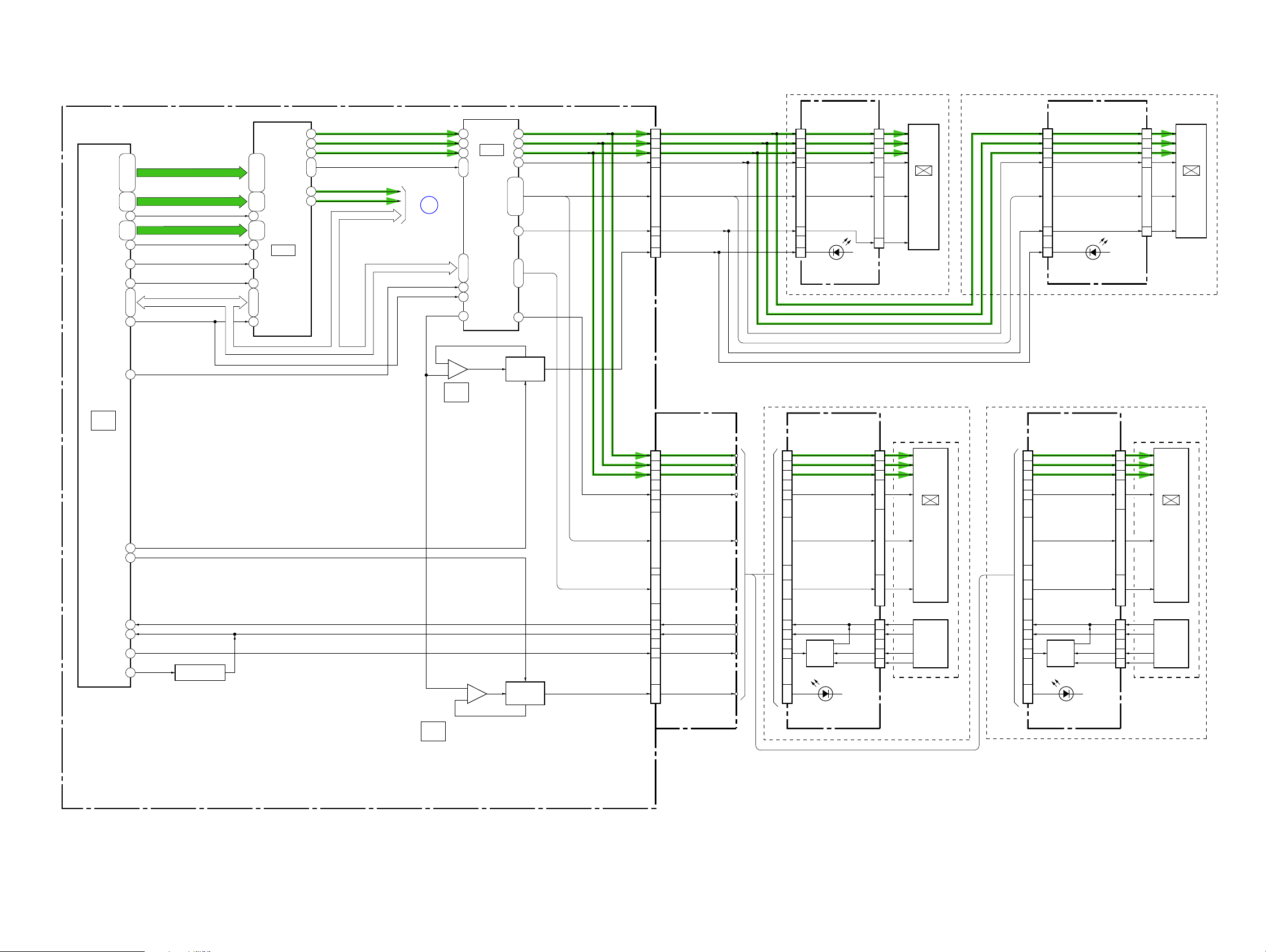
3-4. OVERALL BLOCK DIAGRAM (4/6)
( ) : Number in parenthesis ( ) indicates the division number of schematic diagram where the component is located.
VC-520 BOARD (5/7)
D32, C34, B33, C33
D35, E34, D33, D34,
E33, F33
E32, G33,
H35 B15
F32, F34
G32, G34,
G35 D12
F35
U27
L18, M19, M18
G20
T27
IC1701
(3/5)
CPU
(5/20 - 7/20)
D26
Y4
DR_VDATA0 – DR_VDATA7
DR_GHDATA0 – DR_GHDATA3
DR_GHPILOT
DR_GSDATA0 – DR_GSDATA3
DR_GSPILOT
DR_VINCK
XCS_IC_2401
BB_SI, BB_SO, XBB_SCK
XBB_RST
XCS_LCD
EVF_BL_ON
PANEL_BL_ON
A18, B19, A20, B21
B17, A17, D18, B18,
A15, A14
B16, A16,
D13, A13
D14, B14,
IC2401
D/A
E21
CONVERTER
(13/20)
H2
J1, G2, H1
J21
AA2
AA4
AA5
K1, K2
AA9
AA11
PANEL_HD, PANEL_VD
IC_2401_Y_OUT
IC_2401_C/PB_OUT
BB_SO, XBB_SCK
PANEL_R
PANEL_G
PANEL_B
5
OVERALL (5/6)
(PAGE 3-5)
BB_SI, BB_SO, XBB_SCK
XCS_LCD
XBB_RST
EXTDA
EVF BACKLIGHT
6
–
5
+
IC3102
(2/2)
CONTROL
(16/20)
34
33
32
42, 45, 44 48, 1
43
3
31
7
EVF_BL_ON
PANEL_BL_ON
IC3101
LCD/EVF
DRIVE
(16/20)
20
21
22
26
16, 30, 24
6 - 9, 12, 14,
10
5, 11, 18
28
Q3105
EVF
BACKLIGHT
DRIVE
CN3101
13
14
12
16
2 - 4, 6, 8 - 11, 15
7
18
CN3102
(1/2)
1
2
3
30 1
17, 19 - 24, 28, 29
EVF_VR
EVF_VG
EVF_VB
EVF_COM
EVF_HST, EVF_HCK1,
EVF_HCK2,EVF_VCK,
EVF_PCG, EVF_REF, EVF_VST,
EVF_EN, EVF_PSIG
EVF_STB
LED_K
FP-573 FLEXIBLE
BOARD (1/2)
PANEL_VR
PANEL_VG
PANEL_VB
COM
HST, HCK1, HCK2,
VCK, PCG, REF,
VST, EN, PSIG
Non MEGA model
BL-021 BOARD
CN5701
6
5
7
3
4, 8 - 11, 13, 15 - 17
12
1
(BACKLIGHT)
Non MEGA model
PD-351 BOARD (1/2)
CN6201
(1/2)
30
29
28
PSIG, HCK1, HCK2,
14, 12 - 7, 3, 2
CN5702
CS, COM
HST, HCK1,
HCK2, VCK,
PCG, REF, VST,
EN, PSIG
D5702
CN6205
COM, CS
REF, HST, PCG,
EN, VCK, VST
VR
17
VG
18
VB
16
5 - 7, 10, 12 - 15, 20 19, 21
STB
11
R
4
G
5
B
3
24, 236 - 8, 11 - 13, 20 - 22
LCD902
COLOR
EVF
UNIT
LCD901
2.7 inch
WIDE
COLOR
UNIT
LCD
MEGA model
MEGA model
BL-022 BOARD
CN5701
6
5
7
3
EVF_HST, EVF_HCK1,
EVF_HCK2,EVF_VCK,
EVF_PCG, EVF_REF, EVF_VST,
EVF_EN, EVF_PSIG
4, 8 - 11, 13, 15 - 17
12
1
(BACKLIGHT)
PD-352 BOARD (1/2)
CN6201
(1/2)
30
29
28
1
PSIG, HCK1, HCK2,
REF, HST, PCG,
EN, VCK, VST
14, 12 - 7, 3, 2
EVF_VR
EVF_VG
EVF_VB
EVF_COM
EVF_STB
D5701
CN6205
COM, CS
CN5702
R
4
G
5
B
3
1, 24, 236 - 8, 11 - 13, 20 - 22
18
19
17
21
12
LCD902
COLOR
5 - 7, 11, 13 - 16, 20
LCD901
2.7 inch
WIDE
COLOR
LCD
UNIT
WIDE
EVF
UNIT
TP_X
AM35
TP_Y
AN34
TP_SEL1
B29
TP_SEL2
B28
05
DCR-DVD110E/DVD115E/DVD310E/DVD410E/DVD610/
DVD610E/DVD710/DVD710E/DVD810/DVD810E_L2
Q1701
TOUCH PANEL
SELECT SWITCH
IC3102
(1/2)
3
+
2
–
LCD BACKLIGHT
CONTROL
(16/20)
1
LCD
BACKLIGHT
DRIVE
Q3101 - Q3104
3-4
RGT, DWN, XSTBY RGT, DWN, XSTBY
27 - 25
14
16
15
11 - 9
TP_X
TP_Y
TP_SEL1
BL_H1 - BL_H3
4 - 6
17
15
16
20 - 22
TOUCH
PANEL
Q6201, Q6202
D6203 – D6205
(BACKLIGHT)
A : VIDEO SIGNAL
RGT, DWN, XSTBY
2, 19, 14
CN6204
TP_TOP
5
TP_L
2
TP_R
1
TP_BOT
I/F
4
TOUCH
PANEL
Non MEGA model: DCR-DVD110E/DVD115E/DVD610/DVD610E
MEGA model: DCR-DVD310E/DVD410E/DVD710/DVD710E/DVD810/DVD810E
4 - 6
17
15
16
20 - 22
TOUCH
PANEL
I/F
Q6201, Q6202
D6203 – D6205
(BACKLIGHT)
CN6204
TP_TOP
TP_L
TP_R
TP_BOT
2, 19, 14
5
2
1
4
TOUCH
PANEL
 Loading...