

Page 1
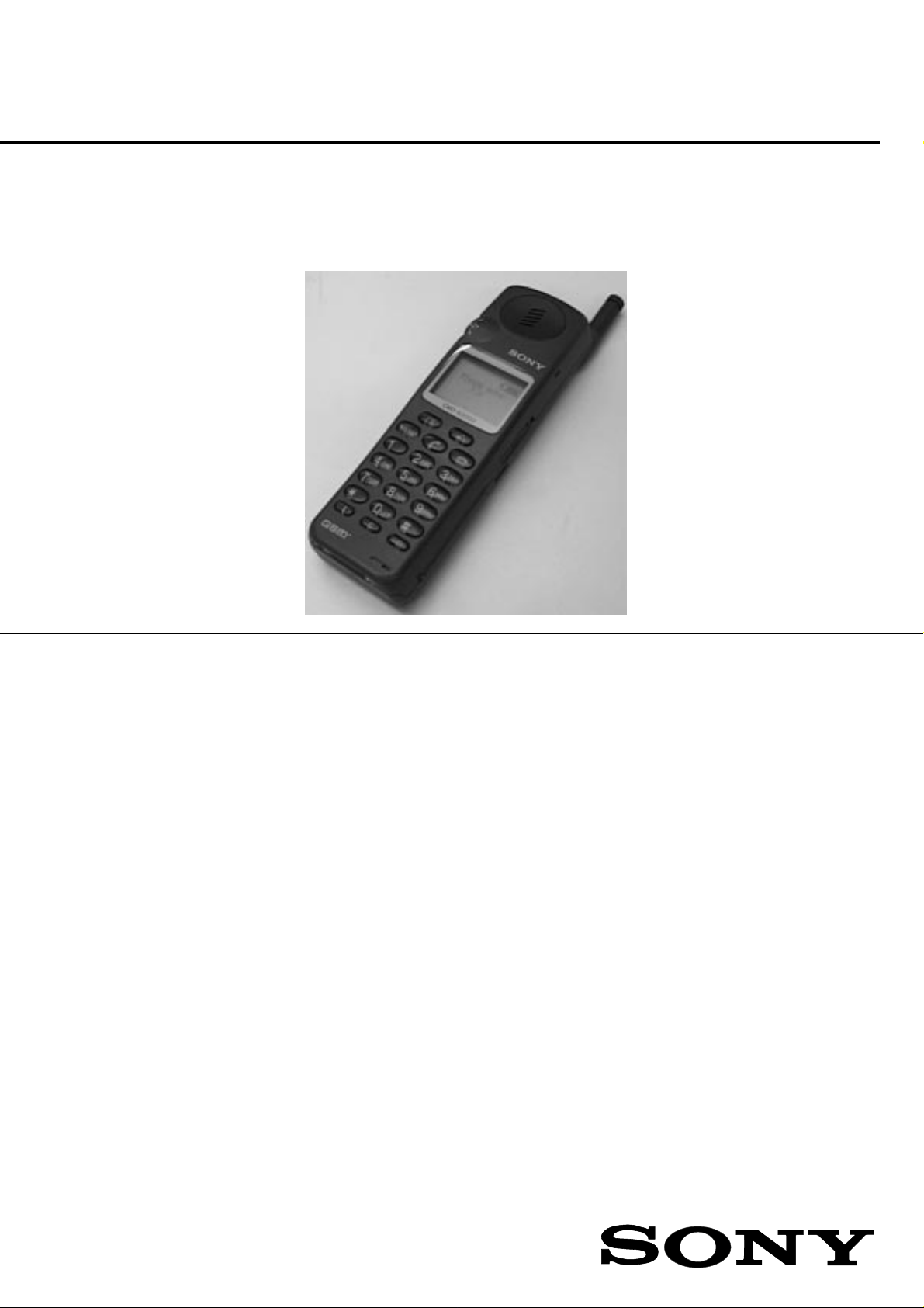
CMD-X200
0
SERVICE MANUAL
AEP Model
UK Model
SPECIFICATIONS
Signalling format GSM PHASE II
Frequency range Transmit: 890 ~ 915 MHz
GSM power class Class 4 (2 W)
SIM chip Pluggable mini SIM card
Display Two-row. resp. four-row full-graphic LCD display + ICON line
Antenna gain – 1.5 dBd (antenna extended)
Channel spacing 200 kHz
Number of channels 124
Frequency stability Transmit frequency drift (synchronized)
RF output power 2 W
Power requirements 3.6 V (battery) 6.5 V (AC adaptor)
Battery life up to 100h standby time
Operating temperature –25°C to +55°C
Storage temperature –40°C to +70°C
Battery pack charging temperature +10°C to +40°C
Dimensions 147.5 mm (H) x 45 mm (W) x 24.5 mm (D)
Weight 160 g
Volume 140 cm
Accessories QN-2000BP (battery pack), QN-2000DTC (desktop charger), QN-2000TC
Design and specifications are subject to change without prior notice.
This appliance conforms with EEC Directive 87/308/EEC regarding interference suppression.
Receive: 935 ~ 960 MHz
Resolution: 97 x 33 pixels = 3201 pixels
< ± 0.1 x 10
up to 10h talk time
(travel charger), QN-2000LINK (PC link), QN-2000PCM (fax and data),
QN-2000CC (car charger), QN-2000KIT (basic car kit). QN-2000HFK
(hands-free car kit), QN-2000HEAD (headset), QN-2000CLIP (belt clip),
QN-2000VAB (vibra alert battery)
-6
kHz
3
PORTABLE DIGITAL CELLULAR TELEPHONE
WITH ACCESSORIES
Page 2
SECTION 1
SONY
GS
GS
1
2
3
5
4
6
9
10
11
12
13
14
15
8
7
16
17
18
19
20 21 22
2
OPERATING INSTRUCTIONS
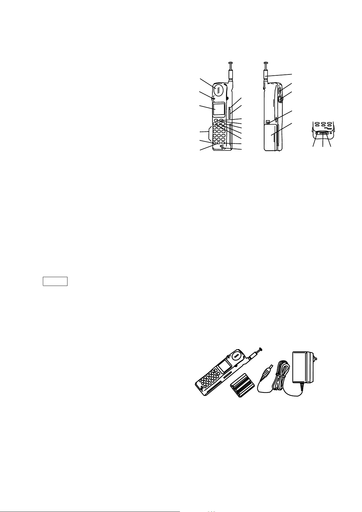
Quick Reference
1 Ear piece 12 Service/Speed Dial Key
2 Jog Dial 13 Exit Key
3 Display 14 Send Key
4 Keypad (alphanumeric keys) 15 Menu Key
5 i Key 16 Antenna
6 Clear key 17 Pop Up Switch
7 Microphone 18 Battery Release Switch
8 Power Key 19 Battery Pack
9 SIM Card Release 20 DC Jack (Charging)
10 SIM Card Holder 21 Battery Contacts (Charging)
11 Voice Mail Key 22 External Connector
Safety Precautions
•
Do not use your phone in an aircraft, hospitals or petrol stations.
• Note that in some countries using a cellular phone without a hands-free kit while driving is not allowed.
• Do not pick up your phone by the antenna or exert excessive force on it.
• Donotexpose yourphone toextreme conditionssuch ashigh humidity/rain,hightemperatures,directsunlight,
caustic/harsh chemicals or dust.
• Do not allow children to play with your phone.
• Take special care in the disposal of your battery, using a special facility where available. Do not puncture or
burn.
• Limit the distance between the mains socket and the phone when charging for easy accessibility.
• Consult your physician or the manufacturer of personal medical devices (pacemakers, hearing aids, etc.)
regarding any restrictions on the use of a mobile telephone.
• Use only Sony-approved batteries and accessories with your phone.
(Accessories)
Warning
Unauthorised batteries, chargers and accessories will invalidate any approvals and warranty given for your
phone and may be dangerous.
Welcome to the Sony CMD-X2000
Welcome to GSM (Global System for Mobile Communication). Your CMD-X2000 complies with this digital
standard which is being implemented in more than 92 countries. The GSM networks are continuously being
extended, so check with your Network Operator/Service Provider regarding current and planned network
coverage (areas of service).
∗
What’s included in your CMD-X2000 kit
The kit should include following :
SONY
• This manual
• One CMD-X2000 mobile phone
GS
• One lithium ion battery pack
• One charger
If one of these parts is missing, please contact your retail dealer immediately.
∗
The basic features of your CMD-X2000
The jog dial (2)
The jog dial is important for quick and easy navigation and operation of the CMD-X2000. In idle mode (the
network operator name appears on the display), press the jog dial once to activate the phone book. In menus
and the standard phone book, rotate the jog dial up or down to scroll through the menu options or phone book
and press the jog dial to make a selection. Press and hold the jog dial (for more than one second) to initiate a
phone call.
3
Page 3
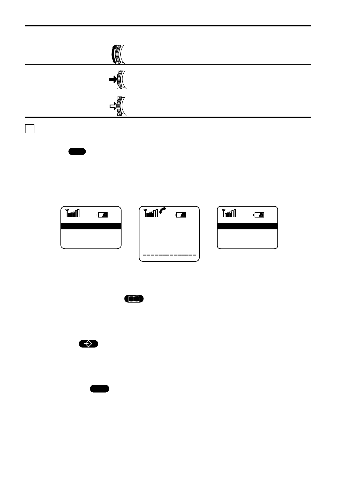
Operation Function
Rotate Scrolls through menu options.
Press
(click)
Selects (highlights) an option in the display.
Accepts an entry made by alphanumeric keys.
Press and hold Dials the phone number selected.
Tip
The send key (14) performs the same function as pressing or pressing and holding the jog dial.
The menu key (15)
MENU
The menu key is context-sensitive and leads you to a menu containing options approprioate for the current
situation. In idle mode, press the menu key to activate the main menu. The main menu offers options to change
your phone settings and set up different features which will be described in the following chapters. Press the
menu key during a phone call to activate menu options which offer dedicated, call-related features (e.g. call
hold). Press the menu key while in the phone book to activate a dedicated phone book menu for different phone
book options (e.g. editing or deleting entries).
Main Menu Dialogue Barbara M.
Divert 1
Control Use 2
Ringer 3
Mic. Off
Call Hold
Send DTMF String
Time, Cost
Main Menu
New Entry
Edit Entry
Delete Entry
The pop up switch (17)
Pop up the switch to unlock the keypad and to answer an incoming call. Slide the pop up switch down to lock
the keypad and to terminate a call (see also “Basic operatiom).
The service number/speed dial key (12)
i
Press the service number key to select a dedicated phone book of service numbers provided by your network
operator/service provider. If the service phone book is unavailable, you can otherwise store up to three speed
dial numbers of your preference as a ersonal “mini” phone book and access these numbers via this dedicated
key (see also “Using the phone book”).
The voice mail key (11)
Press the voice mail key to automatically dial your voice mail numberprovided by your network operator/service
provider (i.e. to listen to your messages, etc.) If this number was not programmed by your network
operator/service provider, you can set it up yourself in the messaging menu by selecting the voice mail option
(see also “Menu operations”).
The i key (information) (5)
i
Press the i key to access additional information about the use of the current menu item or feature when the i
icon appears in the display. Press the i key in the phone book to display information about the available memory
of your phone book.
The menu
Change the service and phone settings using the menu system of your CMD-X2000 (see also “Menu
operations”). Simply press the menu key to select themain menu. Rotate the jog dial to scrolll through the menu
options. Press the jog dial to select the highlighted item.
Press the number key corresponding to the menu option as a short cut to highlight and select that item. For
example, press key number 4 in the main menu to directly access the time, charge menu.
4
Page 4
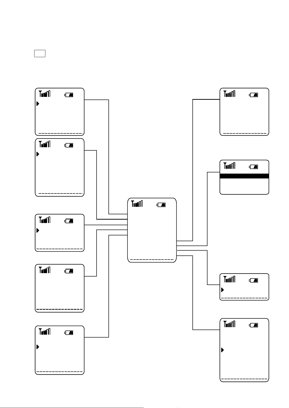
Simply press the exit key (13) once to go one step back in a menu; press and hold the exit key to exit the menu
and return to idle mode. After a lapse of 2 minutes, the CMD-X2000 automatically exits the menu and defaults
to idle mode.
See the following menu tree for easy reference and navigation through the menu system.
Note
Some menu options may be network or subscription dependent. Please contact your network operator/ service
provider for further details.
Time, ChargeDivert
If not Reachble
If no Reply
All Calls
?
If Busy
All Unanswered
Clear All
Control Use
PIN
PIN2
Network Passw.
Phone Code
?
Limit Calls Out
Limit Calls In
SIM Lock
Loan Phone
Last Call
Total Calls
Auto Display
1 Minute Beep
Charge Rate
Charge Limit
Phonebook
Barbara M.
Colleen E.
Sonja T.
On/Off
Ringer
Volume
Tone
Distinct. Tone
Messaging
Voice Mail
View Messages
Edit Messages
Create New Msg
Local Area Info
Configure SMS
GSM Service
Network Info
Auto Network
Network List
Incognito
Fax/Data Mode
Call Waiting
Main Menu
Divert 1
Control Use 2
Ringer 3
Messaging 4
GSM Service 5
Time, Charge 6
Phonebook 7
Car Use 8
Setup 9
Car Use
Auto Answer
Auto Power off
Setup
Language
Key Settings
Any key Answer
Illumination
Own Greeting
Service Tones
Power Save Mode
Master Reset
Phone Status
5
Page 5

SECTION 2
DISASSEMBLY
1.Remove Simcard holder , antenna (no tool needed),
battery cover and battery.
3.The back lower case assy and battery plate can now
be separated from the upper case.
2. Remove 4 screws.
4. Remove 4 screws from the upper shielding.
5.The electronical part (= MMI boardwithRF/logic unit
as a whole) is held onto the upper case by a claw
on either side. Therefore , in order to release the
uppercase from the electronical part , squeeze both
sides of the upper case gently to the outside and at
the same time push the electronical part upward.
6. The upper case can now be taken away , speaker,
earphone m icrop hone and keyboard are now
accessible.
6
Page 6

7.Toseparate the RF/Logic block from the MMI board,
lift the spring slightly using a small flat screwdriver
while pushing it to the right with your finger.
8. When the spring is taken off, the RF/Logic unit can
belifted. Thecentre bolt (MMIsupport) cannow also
be taken away. Note that the centre bolt is not
symmetric (comparing both ends). The shorter end
fits into the MMI board.
9. When unsoldering orresoldering the coax cable,be
very precise and use the exact correct amount of
soldering, not too much, not too little. The RF level
towards the car connector can be affected
drastically by bad solderings.
10. The RF/Logic unit is 1 item, it should never be
disassembled. Separate parts are not
available. The IMEI number in the RF/Logic
memory has to be equal to the IMEI number on
the battery plate assy.
7
Page 7

SECTION 3
LEVEL 1 TROUBLESHOOTING CHART
Insert
SIM card
Switch on
Does the
telephone
switch on?
Yes Yes
Does the
telephone
log on?
Yes Yes
Is a
call
possible?
Yes
No
Insert new
No No
battery
Does
the original
SIM card work
on another
set?
No
No
Does the
telephone
switch on?
SIM probably
defective
Is an
incoming call
possible?
Yes
Is the
audio quality
acceptable while
a call is in
progress?
Yes
Level 1
repair
Local level 1 operation
No
No
Level 2/3
repair
8
Page 8

SECTION 4
PROGRAMMING INSTRUCTIONS
1 Hardware Setup
The software programming setup requires a PC (386 type or higher) and the bootadaptor kit. The boot adaptor
kit consists of bootadaptor, cables and power supply.
• Connect RS232 cable from bootadaptor to com-port of PC (com 1 or com 2)
• Connect power supply (9V) to bootadaptor
• Connect bootadaptor to CMDX2000
2 Software setup
Thesoftware is distributed automaticallyafterregistration of the bootadaptor.Install the software intoadedicated
directory on the PC. It is ADVISABLE to perform the software programming ONLY starting from DOS, not under
Windows. If starting under windows, there is a slight chance that the windows program, still running on the
background, causes interruptions which might prove to be fatal.
Following files are available :
• swupinst.exe : this program enables you to choose language, to check com-port and to check connection to
the CMDX2000
• swup.ini this file contains language setting and com-port setting (can be changed from swupinst.exe or by
using editor program)
• langgrpX.xbi : each langgrpX.xbi file contains the full software package for a certain language group, when
starting the programming the correct choice of language group has to be made by operator
• swup.exe : start program for software programming, following options are possible :
– swup.exe /i : information on the software version is shown
– swup.exe /h : a small helpfile is shown
– swup.exe langgrpX.xbi : starts the software programming sequence for a language group.
3 Programming instructions :
•
Make sure a battery is in the CMDX2000.
• Make sure the bootadaptor is powered.
• Connect CMDX2000 to bootadaptor and check proper connection from bootadaptor to PC.
• Start PC under DOS, or exit windows.
• Start software programming sequence with instruction: swup.exe langgrpX.xbi (X = number of language
group, depending on available language group files).
• The software update will now be performed automatically, no further intervention is needed.
9
Page 9

SECTION 5
EXPLODED VIEW
10
Page 10

SECTION 6
SPARE PARTS AND ACCESSORIES LIST
Ref. No. Part Number Description
1 1-501-941-11 Antenna
2
3
4
5
6 3-015-724-01 Sim holder
7
8
9
10
11
12
13
14
15
16
17 1-779-749-21 I/O connector
18
19
20
21
22 1-782-532-11 cable, coaxial
X-3374-024-1 Case (lower)
X-3374-025-1 Plate, battery assy
3-018-366-01 Screw torx 2.0 x 6
3-015-723-01 Screw torx 1.8 x 16
3-015-725-01 Cover ringer
1-759-436-21 Ringer
1-475-287-21 Jog dial
1-572-688-22 Switch key lock
8-719-053-07 Led (sml310mtt86)
X-3374-026-1 Case (upper)
1-505-702-11 Speaker
3-015-741-01 Ear piece
1-542-329-11 Microphone
3-015-718-01 Key main
1-528-804-11 Battery
1-779-751-21 Connector, Sim
3-015-722-01 Spring, fixed
3-015-719-01 Support MMI
Jigs & tools
Accessories
9-948-005-89 Bootadaptor (programming jig)
S-0953-004-0 Torx T6 screwdriver
1-475-286-11 AC adaptor
11
Page 11

9-948-423-10
Sony Customer Relations & Service Europe
European Technical Support
12
English
Printed in Belgium
1997.10
Published by ETS
 Loading...