

Page 1

SERVICE MANUAL
%
CMD-CD18
Chinese-Mode!
SPECIFICATIONS
Signalling format
Frequency range E-GSM 900 MHz,Transmit: 880 -915 MHz
GSM power class Class 4 (2W)
DCS power class Class 1 (1W)
SIM chip Pluggable mini SIM card
Display
Channel spacing 200 kHz
Number of channels E-GSM: 174
Frequency stability
RF output power GSM: 2W
Battery life
Dual-Band
Receive: 925 - 960 MHz
DCS 1800 MHz , Transmit: 1710 - 1785 MHz
Receive: 1805 - 1880 MHz
High resolution full graphics display
Resolution: 97 x 33 pixels
1 header line for icons
-3 lines X 16 large characters
DCS: 374
Transmit frequency drift (synchronized)
< ± 0,1 p.p.m
DCS: 1W
Standby: 50h-180h standard battery
70h -250h extended battery
Talk time : 2h30 - 6h standard battery
PORTABLE DIGITAL CELLULAR TELEPHONE
WITH ACCESSORIES
Page 2

Power requirements
Operating temperature
Accessories operating temperature
Battery pack charging temperature
Dimensions
Weight
Volume
Supplied accessories
Optional accessories
Design and specifications are subject to change without prior notice.
This appliance conforms with EEC Directive 87/308/EEC regarding interference suppression.
3.8 V (nominal)
-10°C to +55°C
± 0°C to +450 C
± QOC to +4QOC
139 mm X 45.5 mm x 26.5
139 g
120 cm3
Power adapter ;
Battery (std.)
Battery (extd.)
Cigar Lighter Charger QNTravel Charger QNHandsfree kit QNEasyCom(SoftModem)QN
PC-Card QNHeadset QNDesktop Charger QN-
ONONQNQNQN-
mm3
■2AC1 (AEP)
2AC2 (UK)
2AC3 (Australia)
CD5BPS
CD5BPE
2CC
2TC
CD5HFK
-2EC
2PCM
2HS
CD5DTC
NOTE
This device contains electrostatic sensitive components. Damage can occur to these components
if the appropriate handling is not adhered to.
Handling precautions:
A working area where Digital Cellular Telephones may be safely handled without undue risk of
damage from electrostatic discharge, must be available.
The area must be equipped as follows:
> All working surfaces must have a dissipative bench mat, safe for use with live equipment,
connected via 1.2Mi2 resistor to a common ground point.
> A quick release skin contact device with a flexible cord, which has a built in safety resistor of
between 5.2MQ and 1.2Mi2 shall be used. The flexible cord must be attached to a
dissipative earth point.
> All containers and storage must be of the conductive type.
Batteries:
This device contains an internal battery in addition to the external battery packs. These batteries
are recyclable and should be disposed of in accordance with national legislation. They must not
be incinerated, or disposed of as ordinary rubbish.
Page 3

TABLE OF CONTENTS
SECTION 1
Specifications
SECTION 2
General Descriptions
2.1 Multi Band............................................................................. 05
2.2 Real Time Clock................................................................... 05
2.3 Vibra Alert Functionality
2.4 Battery Safety........................................................................05
2.5 Battery Capacity....................................................................06
2.6 Accessory Interlace...............................................................06-07
2.7 RF Antenna connector / antenna switch
2.8 Languages
............................................................................
SECTION 3
Available Accessories
3.1 Hands free kit QN-CD5 HFK.....................................09
3.2 Cigar Lighter Charger QN-2 CC............................................09
3.3 Travel Charger QN-2 TC
3.4 EasyCom-SoftModemQN-2 EC
3.5 PC Card QN-2 PCM
3.6 Head set QN-2 HS
3.7 Desktop Charger QN-CD5 DTC.....................................10
3.8 Extended Battery QN-CD5 BPE.....................................10
........................................................
...............................
............................................
............................................
.........................................
............................................
(see Cover sheet)
05
08
08
09
09
10
10
SECTION 4
Operating Instructions
4.1 Basic Features.....................................................................11
4.2 Icon Glossary.......................................................................12
4.3 Menu Qverview
....................................................................
SECTION 5
5.1 Disassembly..........................................................................14-15
5.2 Interface to GSM-Tester........................................................16
13
Page 4

SECTION 6
Programming Instructions
6.1 Requirement..........................................................................17
6.2 Hardware set-up....................................................................17
6.3 Software set-up
6.4 Display contrast adjustment
.....................................................................
..................................................
SECTION 7
7.1 Block Diagram - Radio Frequency........................................20
7.2 Block Diagram - Baseband
...................................................
SECTION 8
Exploded View
............................................................................
SECTION 9
9.1 Spare Parts and Accessories List........................................23
17-18
19
21
22
Page 5

SECTION 2
GENERAL DESCRIPTIONS
2.1 Multi-band :
CMD-CD18 support E-GSM 900 and DCS 1800 multi-band functionality.
Because the usage of multi-band depends on network capabilities, the phone is able to operate as a single band
mobile in GSM 900 as weil as in DCS 1800; In addition it supports the extra functionality required for multi-band
mobile stations: lnter-band/”seamless” hand-over, channel assignment, cell selection and re-selection, all between
both bands within a Public Land Mobile Network.
The manual and automatic PLMN selection in both bands is given.
The user does not need any special action to use the multi-band functionality of the phone.
Users are able to manually roam between PLMN’s operating in GSM 900 and DCS 1800 bands.
The CMD-CD18 is a phase II, GSM 900 class 4, DCS 1800 class 1 mobile phone.
The nominal maximum output power for GSM 900 is 2W, for DCS 1800 1W.
2.2 Real Time Clock (RTC):
The real time clock is integrated into the phone.
When the mobile is switched on the RTC is powered via the CPU.
When the phone is powered down, the RTC is powered from the main battery via it’s own low quiescent current
regulator.
When the main battery is low or removed, a back-up battery keeps the clock alive.
After the main battery has reached a voltage level of 3.5V the RTC keeps the time for 10 days.
After the main battery is removed the RTC keeps the time for 10 min.
2.3 Vibra Functionality
The vibrator is a 1.3V device with a vibrating frequency fixed at 120Hz (±20%) and located in the handset.
A general port pin of the CPU controls the switch mode of the vibration motor. It is powered directly from the
battery by an interface control unit. If the mobile is in the phase of switching on or off the vibrator is off at ail times.
2.4 Battery Safety
The battery pack contains a safety circuitry. The charging circuitry and the safety circuitry together guarantee a
double fail-safe battery pack. This means that each component can be either short or open and still all the safety
requirements will not be violated.
The safety concept protects against:
Over voltage: The charging is stopped when Battery Voltage (Vbat) reaches (4.24V- 4.3V). The charging resumes
when Vbat falls below (4.1 IV - 4.23V).
Under voltage: When the cell voltage drops below (1.3V - 1.7V) the cell is disconnected for discharging.
Charging is still possible.
Page 6

2.5 Battery Capacity:
Standard Battery
Extended Battery
The phone can be charged even during making phone calls.
However, the shortest charging time will be reached when the phone is switched off.
As the charging circuit is integrated in the battery pack, the phone cannot be powered up by the charger without the
battery pack being attached.
10OOmAh typical
1450mAh typical
Ll-ion QN-CD5BPS Li-ion QN-CD5BPE
2.6 Accessory interface
The table explains what kind of pins the phone supplies to the different accessories.
Pins
Charger
GND
18
V
Charge
1/2
V
ACC_
power
3
Audio
IN
14
Audio
Out
13
ACC
ID
11
ACC
Detect
6
TX
(OUT)
9
RX
(IN)
10
AGND
12
CLC
Desktop charger V
Head set V
HFK V V V
PCMCIA
EasyCom
V V
V
V
V
Connector layout
V V
V
a/
18 2
V V
V
a/
a/
a/ V V
a/
V
V
V
V
V
V V
Page 7

The connector comprises the following pins:
Detection:
The detection of accessory is done by the charge pin and the detect pin.
Any accessory with an active charge will wake up the phone.
The insertion and removal of the charger (Cigar Lighter Charger, Desktop-Charger, AC-Charger) is detected via
polling. To reduce the power consumption the polling can take up to 5 sec.
The insertion and removal of other accessory is detected via an Interrupt. This detection is only possible when the
phone is powered up.
ID:
The ID pin indicates what kind of accessory is connected.
ACC power:
ACC-power has different functionality with different accessories. ACC-power supplies power to the headset
(min.2.7V and min. 10 mA) or will be used as a signaling pin for the Hands Free Kit.
In the car-kit environment the ext. Vbat indicates that a phone call is accepted/in progress. This information is used
by the car-kit to power up the audio section of the car-kit, mute the car stereo and keep the car-kit powered up
even when the ignition is switched off.
Due to the fact that the ID of the accessory is detected first, the ACC power is not current limited (protected).
RX and TX:
This is the communication interface to the PCMCIA card “QN-2PCM” or the PC-link cable ’’QN-2EC”.
Audio In and Audio Out
These pins build the audio interface to the Head-Set and the Hands Free Kit.
Audio IN:
To limit the noise which is coupled on the Mic-line, the Mic amplifier in the Hands Free Kit “QN-CD5HFK” and
Head-set “QN-2HS” have an output 280mVrms into lOkii.
Audio OUT: >
The single ended output delivers 265mV into a 32Q load.
Page 8

2.7 RF Antenna connector / antenna switch
To connect an external antenna for accessory use, the CMD-CD18 contains a stable RF connector with an
integrated mechanical switch. This connector is placed on the PWB. The integrated mechanical switch switches
between the helix antenna and the external RF antenna connection. The switching criterion is mechanical pressure
from the RF accessory connector.
2.8 Languages
The CMD-CD18 supports the following languages:
Chinese (Simpl.)
Chjnese ( Trad.J^
English
Page 9

SECTION 3
ACCESSORIES
3.1 Hands Free Kit
The Hands Free Car Kit QN-CD5HFK is designed to offer superior speech quality and Full Duplex speech
transmission. In Full Duplex operation both parties can speak simultaneously. The Car Kit has a RF connector for
the use of an external antenna to offer a high quality radio link to the base station. It is a one box design for quick
and easy installation.
Specifications;
Input voltage
Rated output voltage
Rated output current
3.2 Cigar Lighter Charger
The QN-2CC Cigar Lighter Charger is only for use in vehicles equipped with a 12-24 volt negative ground electrical
system. This Charger is intended for charging purposes only and not for making/receiving phone calls in the car.
DC 12V-24V, negative ground
5.0V
500mA
Charging Time:
Full charging can take up to -3 hours, but will be longer if the CMD-CD5 is switched on or if the temperature is
outside the 0°C - 45°C operating range.
Specifications;
Input voltage
Rated output voltage
Rated output current
DC 12-24V, negative ground
5.0V
500mA
3.3 Travel Charger
The Travel Charger QN-2TC is a small and lightweight device. It has a full Input Voltage Range from 100-260Volts.
Using a standard cable makes the connection to the mains socket.
Specifications:
Input voltage
Rated output voltage
Rated output current
100 to 260 V
5.0V
500mA
3.4 EasyCom (Soft Modem)
The EasyCom QN-2EC Data Cable connects the phone to a PC via a RS 232 cable. It supports SMS and
Phonebook function as well as Full Data/Fax Capability 9.6 Kbps.
This configuration is available for Windows 95/98.
Page 10

3.5 PCMCIA Card
The functionality of the PC Card QN-2PCM is the same as the Data Cable QN-2EC.
3.6 Headset
The Headset QN-2 HS supports full Handsfree Operation, Auto Answering to incoming calls, as well as with
microphone muting function.
3.7 Desk Top Charger
The desktop charger QN-CD5 DTC can charge either the Standard or Extended battery with the phone attached.
The Desk Top Charger gets its power supply via the Power adapter or the Travel Charger QN-2TC.
Specifications:
Input voltage
Rated output voltage
Rated output current
DC 5V
5.0V
500mA
3.8 Extended Battery
Specifications:
Lithium Ion Battery
Maximum output voltage
Nominal output voltage
Capacity
QN-CD5 BPE
DC 4.2V
DC 3.8V
1450mAh
10
Page 11

SECTION 4
OPERATING INSTRUCTIONS
The Basic Features of Your CMD-CD18
The Jog Dial
The Jog Dial provides One-Handed Operation navigated by your left hand, freeing your right hand for other activity
like taking notes, etc. Give the Jog Dial a quick turn in either direction in standby mode to spin through the main
menu options. With one simple press of the Jog Dial in standby mode (the Network Operator name appears on the
display), the Phonebook is at your fingertips. Press and hold the Jog Dial (for more than one second) to call a
Phonebook selection or number on the display.
Operation Function
Rotate
Press
(click)
Press and hold
Function
Scrolls through menu options.
Selects an option (highlighted) in the display.
Accepts an entry made by alphanumeric keys.
Dials the phone number selected.
Exits from one menu to the previous one.
The Menu Key
In standby mode, press the Menu key and then use the Jog Dial to spin through the Main Menu with options to
change your phone settings and access different features. See also Menu Operation.
The Manner key
This is the key to good mobile phone manners. Press (.iiQjonce to quickly turn the ringer and all tones to silent
mode to avoid disturbance. Just press twice and the ringer is restricted to a discrete single beep. Press again to
turn on the Vibra Alert without the ringer; once more to turn on the Vibra Alert and ringer simultaneously; and again
to turn the Vibra Alert and single beep ringer. To turn the ringer on again, simply press Cl 18) again.
For your convenience, pressing (|ig)in standby mode will toggle between the two last settings. However when the
phone is ringing, pressing(iiS)once will always turn the ringer and all tones to silent mode. The icons shown
above will help you to see your Manner Key setting at a glance in standby mode.
During a call you can also press (ij[8)again to turn on the microphone. For your reference, the options you activated
using Qii8)are indicated by an icon in the display. See also Icon Glossary.
-iS
The Voice Mail Key (j
To speed dial your Voice Mail, press and hold the to automatically dial your “personal answering service” to
listen to messages, etc. See also Phonebook, Voice Mail.
The Keypad Lock 0~n
Your CMD-CD18 can be locked to avoid involuntary dialing or menu scrolling especially when carrying your mobile
phone. Simply press followed by key to lock your CMD-CD18 keypad and even the Jog Dial restricting
any activity EXCEPT emergency calls (112). It is still possible to answer an incoming call T and even reject an
incoming call by pressing when the keypad is locked. Simply repeat the key combination then in
order to unlock your phone again.
11
Page 12

Icon Glossary
Your phone lets you see at a glance if you have missed calls, have messages waiting, and the status of options
you have selected (like if you have diverted your phone or turned the ringer off). Sony has developed the following
icons to provide you with a quick overview of your mobile activity:
ICON
O-n
Q£>
rTTTH
Trill
r
►
>
Explanation
Keypad locked
SMS Message (flashing = message storage full)
Voice mail Notification
Battery strength (flashing = battery level low)
Network strength
Network not available (no calls possible)
Active call
Incoming call
Option activated
Option deactivated
li
mu
UtPi-
€ J
Missed calls
Divert option activated
Vibra Alert activated
Vibra Alert + Ringer activated
Vibra Alert + Single Beep activated
Ringer switched to volume 0
Ringer and all tones switched to Silent Mode (off)
Ringer switched to Single Beep
Ringer Volumes choices
Speaker Volume
Microphone Mute
12
Page 13

Menu Overview
Rotate the Jog Dial or press the Menu key from standby mode to access the main menu:
DIVERT
c
DIVERT
If not
Reachable
If No Reply
If Busy Service Centre
All Calls Settings
Clear All
► -►
MESSAGING REDIAL
LIST
Read Last Calls Security Caller ID
Create Received Calls Network
Missed Calls Time, Cost
Clear All
Local Area Info Ringer Tone
Iwl ^
CONTROL PRE
FERENCES
Select Line* Calculator
Services
Language
Ringer
Volume
1 Minute Beep
Key Click Sound
DTMF Tones
Illumination
TOOLS
Clock
Calendar
Data Services
Network-dependant
Auto Redial
Auto Answer
Any Key Answer
Welcome Message
Factory Reset
13
Page 14
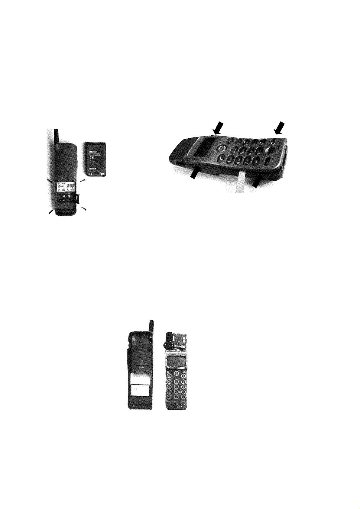
SECTION 5
DISASSEMBLY
IMPORTANT NOTE :
The IMEI Sticker mounted on the main board (visible from the battery compartment) should not be removed at all.
The IMEI number is the electronic identification of the hardware, and it is stored electronically.
There should be no discrepancy between the number on the sticker and the number within the set logic allowed.
Remove the battery and the 4
screws in the battery compartment.
Note that the SIM card is also
located in this area
Insert the hook release jig (p/n 3-043-180-01) in the gap
between upper and lower case. Then gently slide the jig in
the direction of the white arrow. This is to release the claws
between the upper and lower case (as indicated by the
black arrows).
Important: Do not insert the hook release jig too deep
into the gap, that might resuit in damaging the PWB
while sliding the jig.
*1« -'
iT'
The front cosmetic and back cosmetic can now be
separated, and the main board can be taken out.
14
Page 15

'*■
The LCD unit can be lifted out in
the way as follows:
1. disconnect the flex cable
2. unsolder the cushion
3. release the LCD assembly
clips from the main board.
IMPORTANT; Do not detach the shield case from the main board
The Vibra Alert unit consisting of
the Vibra motor, Capacitor and
the flex cable, is attached to the
shield case. It is removed by
disconnecting from the 9pin
connector.
I
i.
i^H
w$.
Parts on the main board specified in the parts list can now be reached.
Re-assembly procedure :
To re-assemble the unit, apply the reverse order of the above mention disassembly procedure.
IB'
O
"X- i
■ ..-.o-'' ’• A. •’
:1
15
Page 16

5.2 Interface to GSM-Tester
CMD-CD18 Level 1 Testing with GSM Tester
CMD-CD18
Battery Pack
Test SIM Card
Service Test
Connector
+
+
Cradle Part No.
3-043-179-01
RF cable output
V
RF input Connector
GSM - TESTER
Level Test Procedure with GSM TESTER recommendation:
• Simulate GSM call processing -to check the functionality of transmit and receive audio of
loudspeaker and microphone.
• Basic GSM transmission & reception parameter testing -to ensure handset’s performance compile
with stand3rd GSM specification.
16
Page 17

Section 6
PROGRAMMING INSTRUCTIONS
6.1 Requirement
• PC (486 type or higher) with Microsoft “Windows” Operating System
• One COM-port free for usage
The Data Transfer Jig (p/n 1-792-172-11)
PREPARATION FOR SOFTWARE UPDATE
DATA
TRANSFER JIG
6.2 Hardware set-up
• Copy all the files to the PC (define own directory).
• Connect the Data Transfer Jig to the PC COM-port (COM 1 or COM 2) and the CMD-CD18 external connector.
• Attach battery pack to CMD-CD18; the CMD-CD18 is powered up from the battery pack.
• The Initial settings of the flash.exe program may not correspond with the normally correct settings. It is highly
advisable to check the settings first (see 3.Software set-up).
3. Software set-up
• Loading new software into the flash
• Start the program flash.exe by double-clicking on its icon in the explorer.
• Select “File’TSettings...” and check if the settings for the “Com Port”, the “Baud Rate” and the “Erase Mode”
are correct. Normally the “Load Options” do not have to be changed. The default values are ;
Com Port:
Fiash.exe
COM 1
Baud Rate ;
Load Options :
Erase Mode :
115200
Both
Program Area, Smart Erase
(! disable melody area for normal software update)
(! disable NVM data area for normal software update)
17
Page 18

Settings
Com Pori—!
<• iOomii !
%
...
.TT»
C Cortó I
Baud Rale—i
; f? 115200 :
r 57600 •
C Cortó i - r 38400
C Com4
OK
After changing the settings, the new values are stored in the file “flash.ini” in the windows directory.
• Click on “FileTOpen..and select an SRE file for downloading.
-The CMD-CD18 software is located in the CD18.SRE file.
-Any other SRE file is either only needed for the program itself, or can be a melody file (see below)
There are 3 kinds of SRE files:- “CD18.sre” for actual software download
: r 9600
Cancel
- “melody.sre” for melody software download
- “fuflash.sre” is an application software (do not use / modify)
Load Options
: r RAM Only ;
; r flash Only j
<* Both
Erase Mode—
r jvlelodyArea
! P" LanguageArea
i P Program Area
! !*” NVM Data Area
r
W Smart Erase
• Press the “LOAD” button of the program.
• Switch on the CMD-CD18.
• Now the program runs automatically.
NOTE
CMD-CD18 Flash Loader can allow for erasing the entire personal phone book entries and all adjustment
settings, by selecting “NVM DATA AREA” only.
A warning message is displayed if this item is selected.
Once the entire phone book entries are erased, there is no possibility to recover the data.
CMD-CD18 Flash Loader can allow for loading different ringer melodies by selecting “MELODY AREA”
only, then load the new file CD18melody.sre.
It is important to change the erase mode settings back to “PROGRAM AREA” and “LANGUAGE
AREA”, in preparation for software update.
18
Page 19

6.4 Display contrast adjustment
1. The hardware set-up for this adjustment is the same as for the software update.
2. Once the hardware connection is made, the CMD-CD18 must be powered on with the battery pack.
3. The display contrast adjustment software is DOS-based, the program name is LCDCONT.EXE.
4. When activating this program (either from within Windows or from the DOS prompt), by default COM port 1 is
selected as the interface between PC and the external connector of the CMD-CD5.
For other COM port selection, go to DOS prompt and enter the following parameter; LCDCONT.EXE -p<port>.
(where <port> is the number of the COM port you want to activate)
For example: to select COM port 2, the correct command to activate the program is: LCDCONT.EXE -p2.
5. When the program is correctly set and activated, the following sequence will appear on the PC;
Waiting for mobile (this message will appear for a few seconds only)
LCD contrast: X (X is a numeric value between 0 and 15)
6. The LCD contrast is adjustable by keying the ( T ) and ( i ) arrows while observing the CMD-CD18 display.
7. Once the best contrast setting is adjusted, just exit from the program and leave the DOS prompt. The adjusted
value will be automatically written into the CMD-CD18 memory.
19
Page 20

SECTION 7
DIAGRAMS
7.1 Radio Frequency (RF) Block Diagram
Rx
The GMSK modulated 900 MHz / 1800 MHz signal received by the antenna is downconverted into the baseband
via an intermediate frequency of 282 MHz. In the transmit direction the digitally GMSK-modulated baseband signal
is modulated to the transmit frequency in the 900 MHz / 1800 MHz bands by means of a modulation loop and the
dual power VCO.
The radio part mainly consists of the RF Synthesizer, Receiver (RX), Transmitter (TX), power amplifiers,
diplexer/switch, antenna connector with integrated switch and antenna.
Tx
20
Page 21

7.2 Baseband Block Diagram
data/address/control signals
21
Page 22

SECTION 8
EXPLODED VIEW
Note:
• The parts with no reference in the exploded view are not supplied.
• The construction parts of an assembled part are indicated with a
collation number in the remark column.
not supplied
22
Page 23

SECTION 9
SPARE PARTS AND ACCESSORIES LIST
Ref. No. Part Number Description Remark
1 X 3377 737 1 Cabinet, Upper Assy Metallic Biack
X 3377 738 1 Cabinet, Upper Assy Metallic Blue
X 3377 739 1
2
3
4
5
6 3 031 803 03
7
8 1 529191 12 Loud Speaker
9
10 1 759 436 21
11
12
13 1 756 040 11
14
15 1 793 605 21
16
17 3 041 807 01 Screw 2.0x10
18 1 127 709 41 Capacitor, Elect 4400MF 99.00% 6.3V
19 1 763 207 11 Motor, Oscillation
20 1 793 615 21
21
3 038 175 01
3 038 176 01
1 754 089 11
A 3647 481 A LCD, Assy
3 038 181 01
1 542 407 11
3 031 801 01
1 418 057 22 Jog Encoder
1 793 633 21
A 3647 660 A Battery Pack Assy
1 675 575 11
Cabinet, Upper Assy Classic Silver
Cabinet Lower
Cap, RF
Antenna
(6)
Cushion, LCD
Rubber Key
Microphone
Ringer
Cushion, Ringer
Battery, Manganese Lithium
Connector (External)
Sim Connector
FFC/FPC Connector
PWB, Flexible
Back up battery
25P
Vibra Alert
9P
Instruction Manual
AC Power Supply
Jigs
3 868 364 41 Chinese (Simplified)
3 868 364 61 Chinese (Traditional)
3 867 714 21 English
1 418 685 21
1 418 679 21 QN-2AC2 UK
3 043 179 01
1 792 172 11
3 043 180 01
9 870 401 11 Service Manual Chinese Model
QN-2AC8 Chinese
Cradle Service-Test Connector
Data Transfer Jig
Hook Release Jig Housing Opening
Software Update
23
Page 24

9-870-401-11
Sony International (Europe)
Digital Telecommunication Europe
Service Promotion Group
English
Printed in Germany
1999.08
Published by DICE
 Loading...