

Page 1

S ON"_ 3-o,3.278.,,_,_
FM/AM
CompactDisc
Player
Installation/Connections
CDX-C7OOOX
CDX-C5OOOX
CDX-C5005
Sony Corporation © 2000
Page 2

Page 3
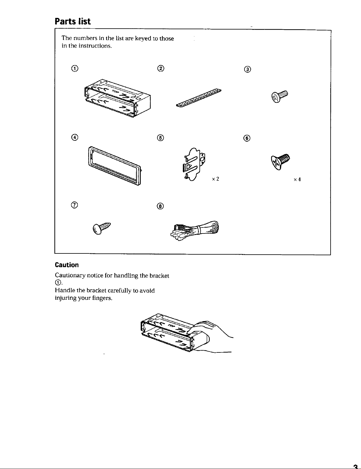
Parts list
The numbers in the list are keyed to those
in the instructions.
if)
@
® @ @
×2
® @
x4
Caution
Cautionary notice for handling the bracket
®.
Handle the bracket carefully to avoid
injuring your fingers.
"4
Page 4
Connections
Cautions
• This unit is designed for negative earth 12 V DC
operation only.
• Be careful not to pinch any wires between the
screw and the body of the car, or this unit, or
between any moving parts such as the seat
railing, etc.
• Connect the yellow and red power input leads
only after all other leads have been connected.
• Be sure to connect the red power input lead to
the positive 12 V power terminal which is
energized when the ignition key is in the
accessory position.
•Run all ground wires to a common earth
surface.
• Connect the yellow cord to a free car circuit
rated higher than the unit's fuse rating, lfyou
connect this unit in series with other stereo
components, the car circuit they are connected to
must be rated higher than the sum of the
individual component's fuse rating. If there are
no car circuitS rated as high as the unit's fuse
rating, connect the unit directly to the battery. If
no car circuits are available for connecting this
unit. connect the unit to a car circuit rated higher
than the unit's fuse rating in such a way that if
the unit blows its fuse, no other circuits will be
cut off.
• The use of optical instruments with this product
will increase eye hazard.
Warning when installing in a car
without ACC (accessory) position
on the ignition key switch
Be sure to press (_ on the unit for two
seconds to turn off the clock display after
turning off the engine,
When you press _ only momentarily, the
clock display does not turn off and this causes
battery wear.
4
Page 5
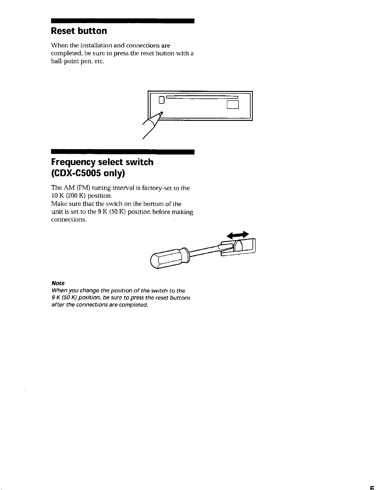
Reset button
When the installation and connections are
completed, be sure to press the reset button with a
ball-point pen. etc.
Frequency select switch
(CDX.C5005only)
The AM (FM) tuning interval is factory-set to the
10 K (200 K) position.
Make sure that the swich on the bottom of the
unit is set to the 9 K (50 K) position before making
connections.
3
Note
When you change the position of the switch to the
9 K (50 K) position, be sure to press the reset buttons
after the connections are completed.
Page 6

Connection diagram
Equipment used in illustrations
(not supplied)
O Front speaker
Haut-parleurs avant
Power amplifier
Amplificateur de
puissance
Haut-parleurs arriere
Rearspeaker
Active subwoofer
Subwoofer actif
CD/MD changer
Changeur de CD/MD
"IV monitor
Moniteur de
la t_le_vision
8
Page 7

Note
For connecting two or more CD/MD changers, the
source selector XA-C30 (optional) is necessary
Notes
• For connecting two or more CD/MD changers, the
source selector XA-C30 (optional) is necessary.
• Be sure to connect the earth cord before
connecting the amplifier.
• If you connect an optional power amplifier and
do not use the built-in amplifier, the beep sound
will be deactivated.
7
Page 8
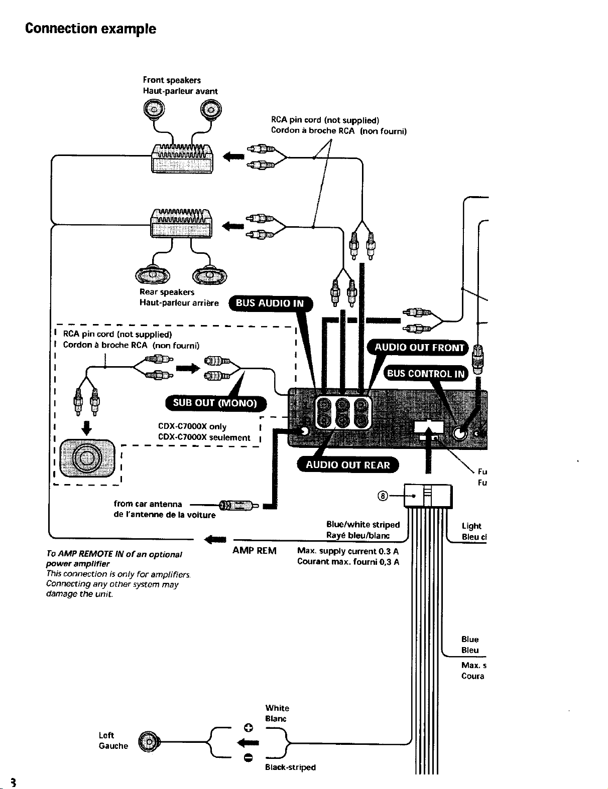
Connection example
Front speakers
Haut-parleur avant
Rear speakers
Haut-parleur arribre
RCA pin cord (not supplied)
Cordon _ broche RCA (non fourni)
RCA pin cord (not supplied)
Cordon b broche RCA (non fourni)
CDX-C70OOXonly !
CDX.C70OOXseulement I
!
I
I
from car antenna
de rantenne de la voiture
To AMP REMOTE IN of an optional
power ampfifier
This connection isonly t_oramplifiers.
Connecting any other system may
damage the unit
Bluelwhite striped
AMP REM Max. supply current 0.3 A
Courant max. fourni 0.3 A
_U
Fu
Light
Bleu ci
Left
Gauche
Blue
Bleu
Max, s
Coura
White
Blanc
Black-striped
Page 9

Fuse (10 A)
Fusible (10 A)
SuppliedwiththeCD/MDchanger
Fourniaveclechangeur de CD/MD
diedwithXA-C30
FourniavecleXA-C30
Rotary commander RM-X4S (not supplied)
Satellite de commande RM-X4S (non fourni)
Insert with the cord upwards.
Insdrez avec le cable vers le haut.
Light blue
Bleu ciel
Blue
Bleu
Max. supply current 0.1 A
Courant max. foumi 0,1 A
to the interface cable of a car telephone
ATT vers le cordon de liaison d'un t(_l_phone de voiture
to the power antenna control lead or power supply lead of antenna
booster amplifier
Notes
• It is not necessary to connect this lead if there is no power antenna or
antenna booster, or with a manually-operated telescopic antenna.
• When your car has a built-in FM/AM antenna in the rear/side glass, see
"Notes on the control and power supply leads."
ANT REM
to the +12 V power terminal which is energized in the accessory
position of the ignition key switch
q
Page 10

White
Blanc
Frontspeake_
Haut-parleurs avant
Rearspeakers
Haut-parleu_ arribre
Left
Gauche
Right
Droit
Le_
Gauche
Right
Droit
@
k=
Black-striped
Noir raye
Gray
Gris
Black-striped
Noir raye
Green
Vert
Black-striped
Noir raye
Purple
Mauve
Red
Rouge
Yellow
Jaune
Black
Noir
Black-striped
Noir raye
Notes on the control and power supply leads
• The power antenna contro! lead (blue) suppfies + 12 V DC when you turn on the tuner.
• When your car has built-in FM/AM antenna in the rear/side glass, it is necessary to connect the power antenna
control lead (blue) or the accessory power input lead (red) to the power terminal of the existing antenna booster.
For details, consult your dealer.
• A power antenna without relay box cannot be used with this unit.
Memory hold connection
When the yellow power input lead is connected, power will always be supplied to the memory circuit even when
the ignition key is turned off.
Notes on speaker connection
• Before connecting the speakers, turn the unit oF_
• Use speakers with an impedance of 4 to 8 ohms, and with adequate power handling capacities. Otherwise, the
speakers may be damaged.
• Do not connect the terminals of the speaker system to the car chassis, and do not connect the terminals of the
right speaker with those of the left speaker.
• Do not attempt to connect the speakers in parallel.
• Do not connect any active speakers (with built-in amplifiers) to the speaker terminal5 of the unit. Doing so may
damage the active speakers. Therefore, be sure to connect passive speakers to these terminals.
10
Page 11

J
Red
Rouge
to the +12 V power terminal which is energized in the accessory
position of the ignition key switch
Notes
• If there is no accessory position, connect to the + 12 Vpower (battery)
temTinal which is energized a_ all times.
Be sure to connect the black earth lead to it first.
• Whenyour car has a built-in FM/AM antenna in the rear/side glass, see
"Notes on the confrol and power supply leads."
Yellow
Jaune
Black
Noir
_]_ to the +12 V power terminal which is energized at all times
Be sure to connect the black earth lead to it first.
to a metal surface of the car
First connect the black earth lead, then connect the yellow and red power
_111_ input leads.
11
Page 12

Installation
Precautions
• Choose the installation location carefully so that
the unit will not interfere with normal driving
operations.
• Avoid installing the unit in areas subject to dust,
dirt, excessive vibration, or high temperature,
such as in direct sunlight or near heater ducts.
• Use only the supplied mounting hardware for a
safe and secure installation.
Mounting angle adjustment
Adjust the mounting angle to less than 60 _.
How to detach and attach the front panel
Before installing the unit, detach the front panel.
[] To detach
Before detaching the front panel, be sure to press
first. Then press _ to open the front
panel, then slide the front panel to the right side,
and pull out the left side of the front panel.
[] To attach
Place the hole (_ in the front panel onto the
spindle _) on the unit as illustrated, then push the
left side in.
12
Page 13

Mounting example
Installation in the dashboard
1
With the TOP marking up
Avec I'inscription TOP vers le haut
Note
When installing this unit: Depending on car type, the mounting angle may not allow the front
panel to open easily. In such a case, remove the silver screw (_) shown below.
When screwing it on again, first lock the lever (_. Attaching the screw without doing so may cause the
unit to break.
2
Bend these claws
outward for a tight fit,
if necessary.
Plier ces grilles pour
assurer une prise
correcte si necessaire.
3
®
14
Page 14

Mounting the unit in a
Japanese car
You may not be able to install this unit in some
makes of Japanese cars. In such a case, consult
your Sony dealer.
TOYOTA
(_ max. size 5 × 8 mm
Dimension max. 5 x 8 mm
_"C__cen_r( c°ns_lee tra,
NISSAN
(_ max. size 5 × 8 turn
Dimension max. 5 x 8 mm
>_"_ _ tg°udta sLheab_:rdd:bcnt;/_ Co°_/: ecen ttale
Bracket
Support
i Exbting parts supplied to your car ---.--
Pi_ces existantes fournies avecla voiture
Support - "_ _ Dimension max.
Bracket
Suppo_
Existing parts supplied to your car
Pi_ces existantes fournies avecla voiture
Note
To prevent malfunction, install only with the supplied
Sony Corporation Printed in USA
 Loading...