

Sony BVM-14G5A, BVM-14G5E, BVM-20G1E, BVM-20G1U, BVM-14G1E Operation And Maintenance Manual
...
TRINITRON® COLOR VIDEO MONITOR
BVM-14G1A/14G1E/14G1U
BVM-14G5A/14G5E/14G5U
BVM-20G1A/20G1E/20G1U
CHASSIS No. SCC-N52D-A (AUS)/J32H-A (AEP)/H99J-A (U/C)
CHASSIS No. SCC-N52E-A (AUS)/J32J-A (AEP)/H99K-A (U/C)
CHASSIS No. SCC-N52C-A (AUS)/J32G-A (AEP)/H99H-A (U/C)
OPERATION AND MAINTENANCE MANUAL [English]
1st Edition
Serial No. 2000001 and Higher
BKM-10R
MONITOR CONTROL UNIT

! W ARNING
This manual is intended for qualified service personnel only.
To reduce the risk of electric shock, fire or injuly, do not perform any servicing other than that
contained in the operating instructions unless you are qualified to do so. Refer all servicing to
qualified service personnel.
WARNING!!
AN ISOLATION TRANSFORMER SHOULD BE USED DURING
ANY SERVICE TO AVOID POSSIBLE SHOCK HAZARD, BECAUSE
OF LIVE CHASSIS.
THE CHASSIS OF THIS RECEIVER IS DIRECTLY CONNECTED
TO THE AC POWER LINE.
SAFETY-RELATED COMPONENT WARNING !!
COMPONENTS IDENTIFIED BY SHADING AND MARK ! ON THE
SCHEMATIC DIAGRAMS, EXPLODED VIEWS AND IN THE PARTS
LIST ARE CRITICAL TO SAFE OPERATION. REPLACE THESE
COMPONENTS WITH SONY PARTS WHOSE PART NUMBERS
APPEAR AS SHOWN IN THIS MANUAL OR IN SUPPLEMENTS
PUBLISHED BY SONY. CIRCUIT ADJUSTMENTS THAT ARE
CRITICAL TO SAFE OPERATION ARE IDENTIFIED IN THIS
MANUAL. FOLLOW THESE PROCEDURES WHENEVER CRITICAL
COMPONENTS ARE REPLACED OR IMPROPER OPERATION IS
SUSPECTED.
ATTENTION!!
AFIN D’EVITER TOUT RISQUE D’ELECTROCUTION PROVENANT
D’UN CHÁSSIS SOUS TENSION, UN TRANSFORMATEUR
D’ISOLEMENT DOIT ETRE UTILISÉ LORS DE TOUT DÉPANNAGE.
LE CHÁSSIS DE CE RÉCEPTEUR EST DIRECTEMENT
RACCORDÉ Á L’ALIMENTATION SECTEUR.
ATTENTION AUX COMPOSANTS RELATIFS ÁLA
SÉCURITÉ!!
LES COMPOSANTS IDENTIFIÉS PAR UNE TRAME ET PAR UNE
MAPQUE ! SUR LES SCHÉMAS DE PRINCIPE, LES VUES
EXPLOSÉES ET LES LISTES DE PIECES CONT D’UNE
IMPORTANCE CRITIQUE POUR LA SÉCURITÉ DU
FONCTIONNEMENT. NE LES REMPLACER QUE PAR DES
COMPOSANTS SONY DONT LE NUMÉRO DE PIÉCE EST INDIQUÉ
DANS LE PRÉSENT MANUEL OU DANS DES SUPPLÉMENTS
PUBLIÉS PAR SONY. LES RÉGLAGES DE CIRCUIT DONT
L’IMPORTANCE EST CRITIQUE POUR LA SÉCURITÉ DU
FONCTIONNEMENT SONT IDENTIFIES DANS LE PRÉSENT
MANUEL. SUIVRE CES PROCÉDURES LORS DE CHAQUE
REMPLACEMENT DE COMPOSANTS CRITIQUES, OU
LORSQU’UN MAUVAIS FONCTIONNEMENT EST SUSPECTÉ.

1 (P)
SAFETY CHECK-OUT
(US Model only)
After correcting the original service problem, perform the
following safety checks before releasing the set to the customer:
1. Check the area of your repair for unsoldered or poorly-soldered
connections. Check the entire board surface for solder splashes
and bridges.
2. Check the interboard wiring to ensure that no wires are “pinched”
or contact high-wattage resistors.
3. Check that all control knobs, shields, covers, ground straps, and
mounting hardware have been replaced. Be absolutely certain
that you have replaced all the insulators.
4. Look for unauthorized replacement parts, particularly transistors,
that were installed during a previous repair Point them out to the
customer and recommend their replacement.
5. Look for parts which, though functioning, show obvious signs
of deterioration. Point them out to the customer and recommend
their replacement.
6. Check the line cord for cracks and abrasion. Recommend the
replacement of any such line cord to the customer.
7. Check the condition of the monopole antenna (if any).
Make sure the end is not broken off, and has the plastic cap on
it. Point out the danger of impalement on a broken antenna to the
customer, and recommend the antenna’s replacement.
8. Check the B+ and HV to see they are at the values specified.
Make sure your instruments are accurate; be suspicious of your
HV meter if sets always have low HV.
9. Check the antenna terminals, metal trim, “metallized” knobs,
screws, and all other exposed metal parts for AC leakage.
Check leakage as described below.
LEAKAGE
The AC leakage from any exposed metal part to earth ground
and from all exposed metal parts to any exposed metal part having
a return to chassis, must not exceed 0.5 mA (500 microampers).
Leakage current can be measured by any one of three methods.
1. A commercial leakage tester, such as the Simpson 229 or RCA
WT-540A. Follow the manufacturers’ instructions to use these
instruments.
2. A battery-operated AC milliammeter. The Data Precision 245
digital multimeter is suitable for this job.
3. Measuring the voltage drop across a resistor by means of a
VOM or battery-operated AC voltmeter. The “limit” indication
is 0.75 V, so analog meters must have an accurate low-voltage
scale. The Simpson 250 and Sanwa SH-63Trd are examples of
a passive VOM that is suitable. Nearly all battery operated
digital multimeters that have a 2V AC range are suitable. (See
Fig. A)
HOW TO FIND A GOOD EARTH GROUND
A cold-water pipe is guaranteed earth ground; the cover-plate
retaining screw on most AC outlet boxes is also at earth ground. If
the retaining screw is to be used as your earth-ground, verify that it
is at ground by measuring the resistance between it and a coldwater
pipe with an ohmmeter. The reading should be zero ohms. If a coldwater pipe is not accessible, connect a 60-100 watts trouble light (not
a neon lamp) between the hot side of the receptacle and the retaining
screw. Try both slots, if necessary, to locate the hot side of the line,
the lamp should light at normal brilliance if the screw is at ground
potential. (See Fig. B)
To Exposed Metal
Parts on Set
1.5kΩ
0.15µF
Earth Ground
AC
voltmeter
(0.75V)
Fig. A. Using an AC voltmeter to check AC leakage.
Cold-water Pipe
Ohmmeter
AC Outlet Box
Trouble Light
Fig. B. Checking for earth ground.


1
TABLE OF CONTENTS
1. OPERATING INSTRUCTIONS
Operating Instructions (BVM-20G1U/14G1U/14G5U) .............................. 1-1
Operating Instructions (BKM-10R) ........................................................... 1-31
2. SERVICE INFORMATIONS
2-1. Circuit Boards Location ............................................................................... 2-1
2-1-1. BVM-14G5A/14G5E/14G5U ..................................................... 2-1
2-1-2. BVM-14G1A/14G1E/14G1U/20G1A/20G1E/20G1U ............... 2-1
2-1-3. BKM-10R....................................................................................2-2
2-2. Disassembly ................................................................................................. 2-3
2-2-1-1. Cabinet Removal
(14G1A/14G1E/14G1U/14G5A/14G5E/14G5U).......................2-3
2-2-1-2. Cabinet Removal (20G1A/20G1E/20G1U) ................................ 2-3
2-2-2-1. FBT Block Assy Removal
(14G1A/14G1E/14G1U/14G5A/14G5E/14G5U).......................2-4
2-2-2-2. FBT Block Assy Removal (20G1A/20G1E/20G1U)..................2-4
2-2-3. E and G Boards Removal and Check .......................................... 2-5
2-2-4. BC and BK Boards Removal and Check .................................... 2-5
2-2-5-1. Card Slot Assy Removal
(14G1A/14G1E/14G1U/14G5A/14G5E/14G5U).......................2-6
2-2-5-2. Card Slot Assy Removal (20G1A/20G1E/20G1U) ..................... 2-6
2-2-6. TA and TB Boards Removal ....................................................... 2-7
2-2-7-1. YA, YB and YC Boards Removal (14G1A/14G1E/14G1U) ....... 2-7
2-2-7-1-1. Bezel Assy Removal (14G5A/14G5E/14G5U) ........................ 2-8
2-2-7-1-2. HA, HB, YA, YB and YC Boards Removal
(14G5A/14G5E/14G5U) .......................................................... 2-8
2-2-7-2. YA, YB and YC Boards Removal (20G1A/20G1E/20G1U) ....... 2-9
2-2-8-1. Picture Tube Removal
(14G1A/14G1E/14G1U/14G5A/14G5E/14G5U).......................2-9
2-2-8-2. Picture T ube Removal (20G1A/20G1E/20G1U) ...................... 2-10
2-2-9. Upper Cover Removal (BKM-10R) .......................................... 2-11
2-2-10. HA and HB Board Removal (BKM-10R)................................. 2-11
2-2-11. HC Board Removal (BKM-10R) .............................................. 2-12
3. SET-UP ADJUSTMENTS
3-1. Preparations.................................................................................................. 3-1
3-2. Focus Adjustment ......................................................................................... 3-2
3-3. Landing Adjustment ..................................................................................... 3-2
3-4. H Blanking Adjustment ................................................................................ 3-3
3-5. V Blanking Adjustment................................................................................ 3-5
3-6. Linearity Adjustment.................................................................................... 3-6

2
3-7. Convergence Adjustment .............................................................................3-7
3-7-1. Static Convergence Adjustment ..................................................3-8
3-7-2. 20-inch Model Convergence Adjustment....................................3-9
3-7-3. 14-inch Model Convergence Adjustment..................................3-10
3-8. G2 Adjustment ...........................................................................................3-11
3-9. White Balance Adjustment.........................................................................3-12
4. SAFETY RELATED ADJUSTMENTS
+B (120V) Voltage Check ............................................................................ 4-1
High Voltage Regulator Check.....................................................................4-1
High Voltage Hold-Down Check ..................................................................4-2
Beam Current Protector Check ....................................................................4-2
5. CIRCUIT ADJUSTMENTS
5-1. BK Board ..................................................................................................... 5-1
5-2. BC Board....................................................................................................5-10
5-3. E Board.......................................................................................................5-11
6. CIRCUIT DESCRIPTIONS
6-1. BK Board Descriptions ................................................................................ 6-1
6-2. BC Board Descriptions ................................................................................ 6-3
6-3. E Board Descriptions ...................................................................................6-4
6-4. C Board Descriptions ................................................................................... 6-7
6-5. Power Supply Circuit Descriptions (G Board).............................................6-7
6-6. Control Unit Descriptions (BVM-14G5, BKM-10R) .................................. 6-9
7. Semiconductors ................................................................................... 7-1
8. EXPLODED VIEWS
8-1. Bezel, Cabinet (14G1A/14G1E/14G1U/14G5A/14G5E/14G5U) ...............8-2
8-2. Card Slot (14G1A/14G1E/14G1U/14G5A/14G5E/14G5U)........................8-4
8-3. Picture Tube (14G1A/14G1E/14G1U/14G5A/14G5E/14G5U) .................. 8-6
8-4. Bezel, Cabinet (20G1A/20G1E/20G1U) ..................................................... 8-8
8-5. Card Slot (20G1A/20G1E/20G1U)............................................................ 8-10
8-6. Picture Tube (20G1A/20G1E/20G1U).......................................................8-12
8-7. Control Unit (BKM-10R)...........................................................................8-14

3
9. ELECTRICAL PARTS LIST ............................................................. 9-1
10. BLOCK DIAGRAM
Overall (1/2) ............................................................................................... 10-2
Overall (2/2) ............................................................................................... 10-3
BK (1/4) ..................................................................................................... 10-4
BK (2/4) ..................................................................................................... 10-5
BK (3/4) ..................................................................................................... 10-6
BK (4/4) ..................................................................................................... 10-7
BC (1/2)...................................................................................................... 10-8
BC (2/2)...................................................................................................... 10-9
E (1/2)....................................................................................................... 10-10
E (2/2)....................................................................................................... 10-11
G...............................................................................................................10-12
HA, HB, HC, HD ..................................................................................... 10-13
11. DIAGRAM
11-1. Printed Wiring Boards................................................................................ 11-1
BK ................................................................................................... 11-2
BC ................................................................................................... 11-4
E ................................................................................................... 11-6
G ................................................................................................... 11-8
C ................................................................................................. 11-10
HD .................................................................................................11-10
P ................................................................................................. 11-10
YA ................................................................................................. 11-10
YB ................................................................................................. 11-10
YC ................................................................................................. 11-10
HA .................................................................................................11-11
HB ................................................................................................. 11-11
HC ................................................................................................. 11-12
TA ................................................................................................. 11-13
TB .................................................................................................11-14
11-2. Schematic Diagrams.................................................................................11-15
FRAME (1/3) ......................................................................................... 11-17
FRAME (2/3) ......................................................................................... 11-18
FRAME (3/3) ......................................................................................... 11-19
BK (1/9) ................................................................................................. 11-20
BK (2/9) ................................................................................................. 11-21
BK (3/9) ................................................................................................. 11-22
BK (4/9) ................................................................................................. 11-23
BK (5/9) ................................................................................................. 11-24

4
BK (6/9) .................................................................................................11-25
BK (7/9) .................................................................................................11-26
BK (8/9) .................................................................................................11-27
BK (9/9) .................................................................................................11-28
BC (1/4) ................................................................................................. 11-31
BC (2/4) ................................................................................................. 11-32
BC (3/4) ................................................................................................. 11-33
BC (4/4) ................................................................................................. 11-34
E (1/4) .................................................................................................11-37
E (2/4) .................................................................................................11-38
E (3/4) .................................................................................................11-39
E (4/4) .................................................................................................11-40
C ................................................................................................. 11-43
P ................................................................................................. 11-44
YA .................................................................................................11-45
YB .................................................................................................11-45
YC .................................................................................................11-45
HD .................................................................................................11-45
G (1/2) .................................................................................................11-46
G (2/2) .................................................................................................11-47
HA .................................................................................................11-49
HB .................................................................................................11-50
HC .................................................................................................11-51
TA .................................................................................................11-53
TB .................................................................................................11-54

1-1
SECTION 1
OPERATING INSTRUCTIONS
This section is extracted from
operation manual.
OPERATION MANUAL
[English]
1st Edition
Serial No. 2000001 and Higher
TRINITRON
®
COLOR VIDEO MONITOR
BVM-20G1U/20G1E/20G1A
BVM-14G1U/14G1E/14G1A
BVM-14G5U/14G5E/14G5A
WARNING
To prevent fire or shock hazard, do not
expose the unit to rain or moisture.
To avoid electrical shock, do not open the
cabinet. Refer servicing to qualified
personnel only.
AVERTISSEMENT
Afin d’éviter tout risque d’incendie ou d’électrocution, ne pas
exposer cet appareil à la pluie ou à l’humidité.
Afin d’écarter tout risque d’électrocution, garder le coffret
fermé. Ne confier l’entretien de l’appareil qu’à un personnel
qualifié.
WARNUNG
Um Feuergefahr und die Gefahr eines elektrischen SchIages
zu vermeiden, darf das Gerät weder Regen noch
Feuchtigkeit ausgesetzt werden.
Um einen elektrischen Schlag zu vermeiden, darf das
Gehäuse nicht geöffnet werden. Überlassen Sie
Wartungsarbeiten stets nur einem Fachmann.
ADVERTENCIA
Para evitar incendios o el riesgo de electrocución, no
exponga la unidad a la lluvia ni a la humedad.
Para evitar descargas eléctricas, no abra la unidad. En caso
de avería, solicite los servicios de personal cualificado.
ATTENZIONE
Per evitare incendi o cortocircuiti, l’apparecchio non deve
essere esposto alla pioggia o all’umidità.
Per evitare scosse elettriche, non aprite l’apparecchio. Per
le riparazioni rivolgetevi solo a personale qualificato.
CAUTION:
Danger of explosion if battery is incorrectly replaced.
Replace only with the same or equivalent type recommended
by the manufacturer. Discard used batteries according to the
manufacturer’s instructions.
ATTENTION
Il y a un risque d’explosion si la pile est mal insérée.
Remplacer la pile uniquement par une pile de même type ou
de type équivalent recommandé par le fabricant. Jeter les
piles usées conformément aux instructions du fabricant.
VORSICHT:
Es besteht Explosionsgefahr, wenn die Batterie inkorrekt
eingelegt wird.
Es darf nur eine identische oder eine vom Hersteller
empfohlene Batterie des gleichen Typs eingesetzt werden.
Entladene Batterien sind nach den Anweisungen des
Herstellers zu entsorgen.
PRECAUCION
Peligro de explosión en caso de haberse instalado
incorrectamente la betería.
Cambie sólo por una del mismo tipo o especificaciones
equivalentes, de entre las recomendadas por el fabricante.
Las baterías viejas se deben eliminar siguiendo las
instrucciones del fabricante.
ATTENZIONE:
Pericolo di esplosione se la pila viene sostituita
scorrettamente.
Sostituirla solo con un’altra uguale o di un tipo equivalente
consigliato dal fabbricante. Gettare via le pile usate secondo
le istruzioni del fabbricante.
Note
The socket-outlet should be installed near the equipment and
be easily accessible.
Remarque
La prise doit être près de l’appareil et facile d’accès.
Hinweis
Zur Trennung vom Netz ist der Netzstecker aus der
Steckdose zu ziehen, welche sich in der Nähe des Gerätes
befinden muß und leicht zugänglich sein soll.
Nota
La toma mural debe estar instalada cerca del equipo y debe
accederse a ésta con facilidad.
Nota
La presa di corrente deve essere situata vicino
all’apparecchio e deve essere facilmente accessibile.

1-2
WARNING: THIS WARNING IS APPLICABLE FOR USA
ONLY.
If used in USA, use the UL LISTED power cord specified
below.
DO NOT USE ANY OTHER POWER CORD.
Plug Cap Parallel blade with ground pin
(NEMA 5-15P Configuration)
Cord Type SVT, three 16 or 18 AWG wires
Length Less than 2.5 m (8 ft 3 in)
Rating Minimum 10 A, 125 V
Using this unit at a voltage other than 120V may require the
use of a different line cord or attachment plug, or both. To
reduce the risk of fire or electric shock, refer servicing to
qualified service personnel.
For customers in the USA
This equipment has been tested and found to comply with
the limits for a Class A digital device, pursuant to Part 15 of
the FCC Rules. These limits are designed to provide
reasonable protection against harmful interference when the
equipment is operated in a commercial environment. This
equipment generates, uses, and can radiate radio frequency
energy and, if not installed and used in accordance with the
instruction manual, may cause harmful interference to radio
communications. Operation of this equipment in a residential
area is likely to cause harmful interference in which case the
user will be required to correct the interference at his own
expense.
You are cautioned that any changes or modifications not
expressly approved in this manual could void your authority
to operate this equipment.
The shielded interface cable recommended in this manual
must be used with this equipment in order to comply with the
limits for a digital device pursuant to Subpart B of Part 15 of
FCC Rules.
For customers in Canada
This Class A digital apparatus meets all requirements of the
Canadian Interference-Causing Equipment Regulations.
Pour les utilisateurs au Canada
Cet appareil numérique de la classe A respecte toutes les
exigences du Règlement sur le matériel brouilleur du
Canada.
Für Kunden in Deutschland
Dieses Produkt kann im kommerziellen und in begrenztem
Maße auch im industriellen Bereich eingesetzt werden. Dies
ist eine Einrichtung, welche die Funk-Entstörung nach
Klasse B besitzt.
Voor de klanten in Nederland
Bij dit produkt zijn batterijen geleverd.
Wanneer deze leeg zijn, moet u ze niet
weggooien maar inleveren als KCA.
• Dit apparaat bevat een Li-ion batterij voor memory back-up.
• De batterij voor memory back-up is vastgesoldeerd op de
BC printplaat BAT1.
• Raadpleeg uw leverancier over de verwijdering van de
batterij op het moment dat u het apparaat bij einde
levensduur afdankt.
• Gooi de batterij niet weg, maar lever hem in als KCA.
Note
Be sure to use the supplied power cord for this monitor, or
this monitor may not conform with the FCC Rules or EEC
Directive 89/336/EEC.
Remarque
Utiliser le cordon d’alimentation fourni pour ce moniteur,
sinon il pourrait ne pas être conforme aux règles FCC ou à la
directive CEE 89/336/EEC.
Hinweis
Dieser Monitor darf ausschließlich mit dem mitgelieferten
Netzkabel betrieben werden, weil anderenfalls der Monitor
nicht mehr die FCC-Vorschriften oder die EG-Richtlinie 89/
336/EWG erfüllt.
Nota
Utilice sin falta el cable eléctrico que viene con este monitor;
de lo contrario el monitor puede no cumplir con los
reglamentos de la FCC o de la directiva 89/336/EEC de la
Comunidad Europea.
Nota
Assicurarsi di usare il cavo di alimentazione in dotazione per
questo monitor, altrimenti il monitor può non essere
conforme alle norme FCC o alla Direttiva CEE/89/336.
ATTENTION - When the product is installed in a rack:
a) Elevated operating ambient temperature
If installed in a closed or multi-unit rack assembly, the
operating ambient temperature of the rack environment
may be greater than room ambient. Therefore,
consideration should be given to installing the equipment
in an environment compatible with the manufacture’s
maximum rated ambient temperature (Tmra: 0°C to 35°C
(32°F to 95°F)).
b) Reduced air flow
Installation of the equipment in a rack should be such that
the amount of air flow required for safe operation of the
equipment is not compromised.
c) Mechanical loading
Mounting of the equipment in the rack should be such
that a hazardous condition is not achieved due to uneven
mechanical loading.
d) Circuit overloading
Consideration should be given to the connection of the
equipment to the supply circuit and the effect that
overloading of circuits might have on overcurrent
protection and supply wiring.
Appropriate consideration of equipment nameplate
ratings should be used when addressing this concern.
e) Reliable earthing
Reliable earthing of rack-mounted equipment should e
maintained. Particular attention should be given to supply
connections other than direct connections to the branch
circuit (e.g., use of power strips).
f) Gap keeping
Upper and lower gap of rack-mounted equipment should
be kept 44 mm (1
3
⁄4 inches).
For the customers in the United Kingdom
WARNING
THIS APPARATUS MUST BE EARTHED
IMPORTANT
The wires in this mains lead are coloured in accordance with
the following code:
Green-and-yellow: Earth
Blue: Neutral
Brown: Live
As the colours of the wires in the mains lead of this
apparatus may not correspond with the coloured markings
identifying the terminals in your plug proceed as follows:
The wire which is coloured green-and-yellow must be
connected to the terminal in the plug which is marked by the
letter E or by the safety earth symbol Y or coloured green or
green-and-yellow.
The wire which is coloured blue must be connected to the
terminal which is marked with the letter N or coloured black.
The wire which is coloured brown must be connected to the
terminal which is marked with the letter L or coloured red.
Ensure that your equipment is connected correctly - if you
are in any doubt consult a qualified electrician.

1-3
1
Table of Contents
Chapter 1
Overview
Chapter 2
Menu
Precaution ............................................................................................... 3
Overview.................................................................................................. 4
Features .......................................................................................... 4
Options ........................................................................................... 5
Connector Panel Configuration ......................................................7
Location and Function of Parts.............................................................9
Front Panel ..................................................................................... 9
Rear Panel .................................................................................... 15
Menu Structure.....................................................................................18
Displaying the Menus................................................................... 18
ADDRESS Menu .........................................................................19
Menu Directories.......................................................................... 20
Basic Menu Operations........................................................................22
Menu Operation Buttons ..............................................................22
Menu Operation............................................................................ 22
Preset Adjustment of the Picture Level Control Knobs —
CONTROL PRESET ADJ Menu ................................................ 25
Overview ......................................................................................25
Structure of the CONTROL PRESET ADJ Menu [A] .................25
Setting Lists in the CONTROL PRESET ADJ Menu.................. 25
Adjusting the Color Temperature — COLOR TEMP ADJ
Menu ...............................................................................................27
Overview ......................................................................................27
Structure of the COLOR TEMP ADJ Menu [B] ..........................28
Setting Lists in the COLOR TEMP ADJ Menu...........................29
Setting the Input Configuration (SET UP 1) — INPUT
CONFIGURATION Menu ...........................................................32
Overview ......................................................................................32
Structure of the INPUT CONFIGURATION Menu [C1] ............32
Setting Lists in the INPUT CONFIGURATION Menu...............33
Assigning the Remote Control Functions (SET UP 2) —
REMOTE Menu ............................................................................35
Overview ......................................................................................35
Structure of the REMOTE Menu [C2] .........................................35
Setting Lists of the REMOTE Menu............................................ 35
Setting the Password (SET UP 3) — PASSWORD Menu ................37
Overview ......................................................................................37
Structure of the PASSWORD Menu [C3] ....................................37
Setting Lists of the PASSWORD Menu ...................................... 37
Setting Power-Up Conditions and Decoder (SET UP 4) —
SYSTEM CONFIGURATION Menu.......................................... 39
Overview ......................................................................................39
Structure of the SYSTEM CONFIGURATION Menu [C4] ........39
Setting Lists of the SYSTEM CONFIGURATION Menu........... 40
(Continued)
Table of contens
2
Setting the Screen Display (SET UP 5) —
ON SCREEN SET Menu ..............................................................41
Overview ......................................................................................41
Structure of the ON SCREEN SET Menu [C5] ........................... 41
Setting Lists of the ON SCREEN SET Menu..............................41
Convergence Adjustments (SET UP 6) — ALIGNMENT Menu..... 42
Overview ......................................................................................42
Structure of the ALIGNMENT Menu [C6] ..................................42
Setting Lists of the ALIGNMENT Menu .................................... 42
Using Extended Functions (SET UP 7) — EXTEND Menu .............44
Overview ......................................................................................44
Structure of the EXTEND Menu [C7].......................................... 44
Setting Lists of the EXTEND Menu ............................................45
Monitor Memory Card Data Operations —
MEMORY CARD Menu .............................................................. 46
Overview ......................................................................................46
Structure of the MEMORY CARD Menu [D] ............................. 46
Setting Lists of the MENU CARD Menu ....................................46
Monitor-to-Monitor Data Copy — COPY Menu ..............................47
Overview ......................................................................................47
Structure of the COPY Menu [E] .................................................47
Setting Lists of the COPY Menu.................................................. 47
Displaying Information About the Monitor — STATUS Menu ......48
Overview ......................................................................................48
Structure of the STATUS Menu [F] .............................................48
Setting Lists of the STATUS Menu .............................................48
Selecting the Monitor to Control — ADDRESS Menu .....................49
Overview ......................................................................................49
Displaying the ADDRESS Menu.................................................49
Cancelling the Remote Control Mode.......................................... 50
Exiting the ADDRESS Menu....................................................... 50
Chapter 2
Menu
Chapter 3
Appendix
Specifications......................................................................................... 51
Connection Cable Specifications for Color Temperature Probes 54
1-4
3
Chapter 1 Overview
Precaution
On safety
•Operate the unit only with a power source as
specified in “Specifications” section.
•The nameplate indicating operating voltage, power
consumption, etc., is located at the rear.
•Should any solid object or liquid fall into the cabinet,
unplug the unit and have it checked by qualified
personnel before operating it any further.
•Do not drop or place heavy objects on the power
cord. If the power cord is damaged, turn off the
power immediately. It is dangerous to use the unit
with a damaged power cord.
•Unplug the unit from the wall outlet if it is not to be
used for several days or more.
•Disconnect the power cord from the AC outlet by
grasping the plug, not by pulling the cord.
•The socket-outlet shall be installed near the
equipment and shall be easily accessible.
On installation
•Allow adequate air circulation to prevent internal heat
build-up.
Do not place the unit on surfaces (rugs, blankets, etc.)
or near materials (curtains, draperies) that may block
the ventilation holes.
•Do not install the unit in a location near heat sources
such as radiators or air ducts, or in a place subject to
direct sunlight, excessive dust, mechanical vibration
or shock.
On cleaning
To keep the unit looking brand-new, periodically clean
it with a mild detergent solution. Never use strong
solvents such as thinner or benzine, or abrasive
cleansers since they will damage the cabinet. As a
safety precaution, unplug the unit before cleaning it.
On repacking
Do not throw away the carton and packing materials.
They make an ideal container which to transport the
unit. When shipping the unit to another location,
repack it as illustrated on the carton.
If you have any questions about this unit, contact your
authorized Sony dealer.
On magnetism
• Do not place the unit near any objects or pieces of
equipment which generate magnetism, such as
magnets, speakers, electric clocks, toys using
magnets, health appliances, etc. Magnetism will
cause picture bounce, oscillations or picture
discoloration.
• Also, the picture may become fuzzy or the colors
may not reproduce correctly due to earth magnetism.
This depends on direction that the unit is installed.
This is not equipment failure. In such a case, simply
degauss the unit.
On the CRT
• Dust accumulates on the CRT easily. Clean the CRT
when necessary with a soft cloth.
The surface of the CRT is easily scratched; therefore,
do not rub or touch the surface of the CRT
unnecessarily since this may result in a scratched
picture tube.
• If you touch the surface of the CRT, you may feel a
weak electrical shock. This is simply static electricity
that is generated on the surface of the CRT. It will not
affect the human body.
4
Chapter 1 Overview
Overview
The BVM-20G1U/20G1E/20G1A are 20 -inch
Trinitoron
®1)
Color Monitors. The BVM-14G1U/
14G1E/14G1A/14G5U/14G5E/14G5A are 14-inch
Trinitoron
®
Color Monitors. They are suitable for
television stations or video production houses, where
precise image reproduction is required.
Features
High resolution picture tube
The HR Trinitron picture tube produces a clear, high
resolution image.
Setup and adjustment with the Monitor
Memory Card
You can use an optional BKM-12Y Monitor Memory
Card to save and load monitor setup and adjustment
data. If your system includes more than one monitor,
you can use the monitor memory cards to exchange
data between monitors. This makes it easy to put all
monitors in your system into the same setup and
adjustment state.
Standard auto alignment system
Decoder chroma and phase adjustment, as well as
color temperature control, may be performed with the
auto alignment system. This makes it possible to
coordinate settings among multiple monitors.
Expandable input capability
The input connector configuration may be easily
modified by simply sliding optional decoder adaptor or
the input expansion adaptor into input option slot at the
rear of the monitor.
4:3/16:9 dual aspect ratio design
This monitor can be changed to either 4:3 or 16:9
aspect ratio with just a simple switching operation. The
screen can be also changed to 4:3 or 16:9 display by
the replacement of a mask (no tools required).
Stable color temperature
The internal beam current feedback circuit maintains a
constant color temperature over long periods of time.
Blue-only mode convenient for monitoring
noise
All three CRT cathodes can be driven with a blue
signal, producing a monochrome display. This mode
is convenient for chroma and phase adjustment, and
for monitoring VTR noise.
Menu operation
The monitor’s various functions and operating
conditions can be set with on-screen menus.
Model
BV-20G1U/20G1E/
20G1A
BV-14G1U/14G1E/
14G1A/14G5U/
14G5E/14G5A
Resolution at the
center of the picture
800 TV lines
800 TV lines
Aperture
grille pitch
0.3 mm
0.25 mm
Separate control unit (BVM-20G1U/20G1E/
20G1A/14G1U/14G1E/14G1A only)
The BVM-20G1U/20G1E/20G1A/14G1U/14G1E/
14G1A are controlled by a separate control unit, such
as an optional BKM-10R/11R Monitor Control unit.
Using a separate control unit reduces the space needed
for the equipment. The BVM-20G1U/20G1E/20G1A
can be connected to the BKM-10R via an optional
BKM-32H Monitor Control Unit Attachment Kit.
Controlling monitor groups
Up to 32 monitors can be controlled from this monitor.
First, using the monitor menus, assign a monitor
address number to each monitor, divide the monitors
into groups, and assign a group number to each group.
Then you can use this monitor to control individual
monitors or monitor groups simply by entering
monitor address or group numbers. You can also
execute the same operation on all connected monitors,
or use this monitor to put all connected monitors into
the same setup and adjustment state.
1) Trinitron
®
is a registered trademark of Sony Corporation.
........................................................................................................................................................................................................

1-5
5
Chapter 1 Overview
Other features
•Compatible with the ISR (Interactive Status
Reporting) system.
•Has both RS-485 serial remote and relay contact
parallel remote control connectors.
•Built-in safe area display and test signal generator for
crosshatch, 100% white signal, 20% gray signal, gray
scale, and PLUGE (Picture Line Up Generating
Equipment).
•Built-in Caption Vision decoder.
•Pulse cross function for simultaneous checking of the
horizontal and vertical synchronization signals. VITS
(Vertical Interval Test Signal) checking is also
possible.
•Auto and manual degaussing.
•Built-in CRT protection circuit.
•This monitor may be mounted in an EIA-standard 19-
inch rack, using an optional BKM-30E20/30E14/
31E14 Rack Mount Kit.
•Controllable from the optional BKM-10R/11R
Monitor Control Unit. (For details about connection
and operation, refer to the BKM-10R/11R Operation
Manual).
Options
For external control
BKM-10R/11R Monitor Control Unit
A controller for this monitor and other BVM-series
video monitors, allowing you to control multiple
monitors from one control unit.
BKM-12Y Monitor Memory Card
Memory cards which can be read and written by the
BVM-14G5U/14G5E/14G5A or BKM-10R/11R.
BKM-14L Auto Setup Probe
This probe allows automatic adjustment of this
monitor’s color temperature.
For screen
BKM-33H20 Monitor 16:9 Mask
Adapts the BVM-20G1U/20G1E/20G1A screen for
16:9 aspect ratio display.
BKM-33H14 Monitor 16:9 Mask
Adapts the BVM-14G1U/14G1E/14G1A/14G5U/
14G5E/14G5A screen for 16:9 aspect ratio display.
For installation
BKM-30E20 Rack Mount Kit
Rack mount kit for mounting the BVM-20G1U/
20G1E/20G1A in an EIA standard 19-inch rack.
BKM-30E14 Rack Mount Kit
Rack mount kit for mounting the BVM-14G5U/
14G5E/14G5A in an EIA standard 19-inch rack.
BKM-31E14 Rack Mount Kit
Rack mount kit for mounting the BVM-14G1U/
14G1E/14G1A in an EIA standard 19-inch rack.
BKM-32H Monitor Control Unit Attachment Kit
Assembly kit for attaching a BKM-10R Monitor
Control Unit to the BVM-20G1U/20G1E/20G1A.
Decoder and input expansion adaptors
The input connector panel is configured by sliding
optional decoder adaptor or input expansion adaptor
into the input option slot at the rear of the monitor.
Note
When installing the adaptor, be sure to perform the
necessary input signal setup with the INPUT
CONFIGURATION menu. If the setup is not
performed, the adaptors may not function correctly.
For information about the INPUT CONFIGURATION
menu, see “Setting the Input Configuration (SET UP 1)—
INPUT CONFIGURATION Menu” on page 32.
BKM-20D SDI 4:2:2 Decoder Adaptor
Includes decoders for serial digital component signals
(525/625). Input/output connectors for three serial
digital channels (component inputs only) and three
analog channels. The input signal type for each
connector is set with the INPUT CONFIGURATION
menu, in accordance with the configuration of the
connector panel.
6
Chapter 1 Overview
Overview
BKM-21D SDI Multi Decoder Adaptor
Includes decoders for serial digital signals (525/625
component and NTSC/PAL composite) and analog
composite signals (NTSC and PAL). Input/output
connectors for three serial digital channels and three
analog channels are equipped. The input signal type
for each connector is set with the INPUT
CONFIGURATION menu, in accordance with the
configuration of the connector panel.
BKM-24N NTSC Decoder Adaptor
Includes decoders for analog composite NTSC signals
and input/output connectors for six analog channels.
The input signal type for each connector is set with the
INPUT CONFIGURATION menu, in accordance with
the configuration of the connector panel.
BKM-25P PAL Decoder Adaptor
Includes decoders for analog composite PAL signals
and input/output connectors for six analog channels.
The input signal type for each connector is set with the
INPUT CONFIGURATION menu, in accordance with
the configuration of the connector panel.
BKM-26M PAL-M Decoder Adaptor
Includes decoders for analog composite PAL-M
signals and input/output connectors for six analog
channels. The input signal type for each connector is
set with the INPUT CONFIGURATION menu, in
accordance with the configuration of the connector
panel.
BKM-27T Tri-Standard Decoder Adaptor
Includes decoders for analog composite NTSC, PAL,
and SECAM signals and input/output connectors for
six analog channels. The input signal type for each
connector is set with the INPUT CONFIGURATION
menu, in accordance with the configuration of the
connector panel.
BKM-28X Analog Input Expansion Adaptor
Increases the number of input/output channels.
Includes input/output connectors for six analog
channels. The input signal type for each connector is
set with the INPUT CONFIGURATION menu, in
accordance with the configuration of the connector
panel.
BKM-48X Analog Input Expansion Adaptor
Increases the number of input/output channels.
Includes input/output connectors for six analog
channels. For each input output connector, either
floating or ground can be selected by the switch inside
the board. The input signal type for each connector is
set with the INPUT CONFIGURATION menu, in
accordance with the configuration of the connector
panel.

1-6
7
Chapter 1 Overview
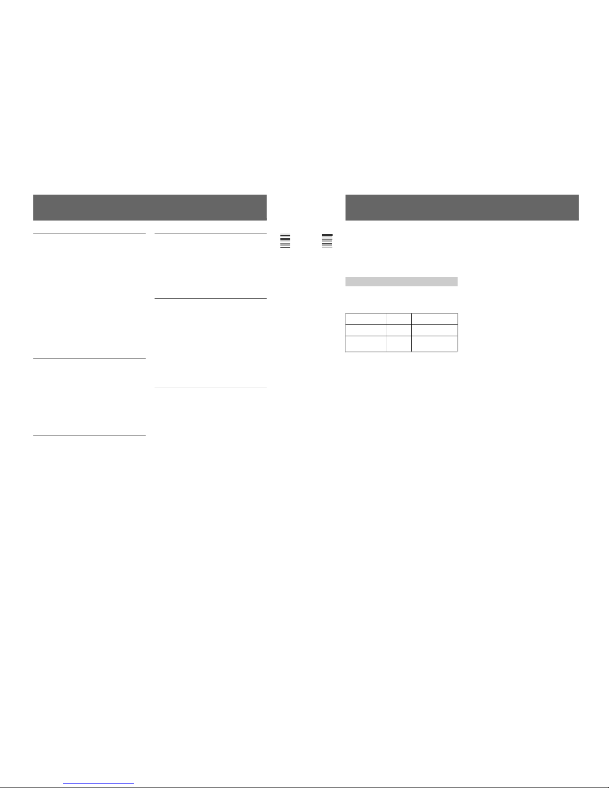
Connector Panel Configuration
The unit comes standard with connectors for one
channel of Y/R–Y/B–Y or RGB. By adding optional
decoder adaptor or input expansion adaptors, the input/
output connector panel can be assembled in a wide
variety of configurations. The signals that each of the
adaptors’ connectors supports are given in the table
below. The type of signal to be applied to each input/
output connector is set with the INPUT
CONFIGURATION menu.
Y/C
PAL
BKM-21D
SDI Multi
Decoder
Adaptor
Adaptor name
BKM-24N
NTSC
Decoder
Adaptor
BKM-25P
PAL
Decoder
Adaptor
BKM-26M
PAL-M
Decoder
Adaptor
BKM-27T
TriStandard
Decoder
Adaptor
BKM-28X
Analog
Input
Expansion
Adaptor
Composite
NTSC
Composite
PAL
Composite
NTSC
Composite
PAL
Composite
PAL-M
Component
525/625
Composite
SECAM
Y/R–Y/B–Y
525/625
RGB
525/625
Y/C
NTSC
Serial
digital
input
Analog
input
®
®
®
®
®
®
®
®
®
®
®
®
®
®
®
®
®
®
®
®
®
®
®
®
®
®
®
BKM-20D
SDI 4:2:2
Decoder
Adaptor
®
®
®
Number of analog
input
Number of digital
inputs
Y/C
PAL-M
336666
6
33––––
–
* : Equipped with floating/non-floating ground mode selector for HAM reduction
®
Notes
The BKM-20D and BKM-21D can not provide proper
active-through outputs if a signal whose format is not
selected in the INPUT CONFIGURATION menu is
input. (If AUTO is selected, input a signal which has
the same format with the signal monitored last.)
For information about the INPUT CONFIGURATION
menu, see “Setting the Input Configuration (SET UP 1) —
INPUT CONFIGURATION Menu” on page 32.
BKM-48X
Analog
Input
Expansion
Adaptor
®
®
6
–
*
8
Chapter 1 Overview
Analog input connectors board
Radiation shield
Note on using the BKM-20D/21D
When the input option slot on the rear of the monitor
has a BKM-20D/21D SDI Decoder Adaptor (option)
installed, if you remove and insert the analog input
connectors board, the radiation shield (see Fig. 2) of
the BKM-20D/21D may be damaged or detached.
Input option slot (with a cover plate)
BKM-20D/21D
Analog input
connectors board
When installing the analog input connectors board
again, remove the BKM-20D/21D temporarily while
carrying out the other operations, then reinstall it.
Fig.1
Fig. 2
Overview

1-7
9
Chapter 1 Overview
Location and Function of Parts
Front Panel
BVM-14G5U/14G5E/14G5A
BVM-20G1U/20G1E/20G1A/14G1U/14G1E/14G1A
0 SHIFT button
1 Tally lamp
2 POWER switch
3 DEGAUSS button
4 Numeric keypad
5 MANUAL adjustment
buttons and knobs
6 Menu operation
buttons
7 POWER lamp
8 STANDBY lamp
9 OVER LOAD lamp
!£ OPTION connector
1 Tally lamp
7 POWER lamp
8 STANDBY lamp
9 OVER LOAD lamp
(Illustration: BVM-20G1U/20G1E/20G1A)
!¡ Function buttons
!™ Monitor Memory
Card slot
!£ OPTION connector
10
Chapter 1 Overview
Location and Function of Parts
This manual explains the location and function of parts
and controls using the control panel of the BVM14G5U/14G5E/14G5A. The explanation applies to
BVM-14G1U/14G1E/14G1A/20G1U/20G1E/20G1A
with the BKM-10R/11R Monitor Control Unit.
1 Tally lamp
With factory settings, the Tally lamp lights when pins
No. 8 and No. 9 of the REMOTE 2 connector on the
rear panel are shorted. By changing the setting in the
REMOTE menu, different pins on the remote
connector can be used to control the tally lamp.
For information about the REMOTE menu, see “Assigning
the Remote Control Functions (SET UP 2) —REMOTE
Menu” on page 35.
2 POWER switch
Press to turn on/off the monitor. By setting with the
ADDRESS menu, it is possible to turn on/off the
power of the specified monitors only, or of all
monitors at the same time.
For information about the ADDRESS menu, see “Selecting
the Monitor to Control - ADDRESS Menu” on page 49.
3 DEGAUSS button
Press to degauss the CRT (every time the monitor is
turned on, the CRT is degaussed automatically). To
degauss again, wait for more than five minutes.
4 Numeric keypad
Use to designate the channel number for the input
signal to be monitored, or to enter the setting values
with the menus.
Numeric buttons
Ent button: Confirms the
values and characters entered
(ENTER button of the menu
operation buttons 6 has the
same function).
Del button: Deletes the values
and characters entered.
Channel number entry method:
(In the explanation below, x and y represent any
digit between 1 and 9.)
When selecting a number from 1 to 9, press the x
button to display channel x. When selecting a
number from 10 to 99, press the 0, x, and y buttons
to display channel xy (a two-digit channel number).
5 MANUAL adjustment buttons and knobs
Each press of one of these buttons turns the button’s
green LED on or off. When the corresponding button
is on (lit), it is possible to manually adjust the contrast,
brightness, chroma and phase by turning the
corresponding knobs. They are also used to enter the
setting values with the menus. It is possible to set the
preset value for each adjusting item with the
CONTROL PRESET ADJ menu.
For Information about the CONTROL PRESET ADJ menu,
see “Preset Adjustment of the Picture Level Control Knobs CONTROL PRESET ADJ menu” on page 25.
Notes
When using the composite SECAM, composite PAL
D, component or SDI (component or composite serial
digital interface) format, note the following.
• The signal phase cannot be adjusted.
• The phase and chroma of RGB signals cannot be
adjusted.
CONTRAST button and
knob
BRIGHT button and knob
CHROMA button and knob
PHASE button and knob:
Changes the items and
settings on the menus
INPUT
1
2
3
Del
4
5
6
0
7
8
9
Ent
PHASE
CHROMA
BRIGHT
CONTRAST
MANUAL

1-8
11
Chapter 1 Overview
6 Menu operation buttons
For more information about menu operation, see “Basic
Menu Operations” on page 22.
7 POWER lamp
Lights when the monitor is put into operation mode
from standby mode (see STANDBY lamp 8) by
pressing the POWER switch 2.
Note
When the STANDBY lamp 8 is blinking, the monitor
cannot be put into operation mode (internal data
initialization is taking place). Wait until the
STANDBY lamp 8 is steadily lit.
8 STANDBY lamp
Lights when the monitor is in standby mode. The
monitor will be in standby mode under the following
conditions:
•The MAIN POWER switch (on the rear panel) is
turned on (the STANDBY lamp will blink for a few
moments after the switch is turned on, then will
light).
•The monitor is changed from operation mode to
standby mode by external control.
9 OVER LOAD lamp
Lights to warn of CRT overload.
MENU button: Press to display the Menus.
ENTER button: Press to confirm the items
and values entered (Ent button on the
numeric keypad 4 has the same function).
UP/DOWN buttons: Press to select the
items and setting values.
UP MENU
DOWN
ENTER
12
Chapter 1 Overview
Location and Function of Parts
0 SHIFT button
Press to select one of the two functions designated to
the function buttons !¡.
Each time the SHIFT button is pressed, the LED turns
on (SHIFT ON: lit in orange) and off (SHIFT OFF: lit
in green).
SHIFT OFF: The functions indicated on the left side
of the function buttons can be used.
SHIFT ON: The functions indicated on the right side
of the function buttons can be used.
(Underscan) button: When this button is pushed in (ON), the picture is
underscanned by 3%, and four ends of the raster is displayed on the screen.
(H delay) button: When this button is pushed in (ON), the picture moves
horizontally, and a horizontal sync signal appears approximately one quarter in the
left edge of the screen.
• The brightness of the picture increases automatically, and it makes it easy to check
the sync part.
• If it is pressed together with the
button, a pulse cross picture is displayed.
(V delay) button: When this button is pushed in (ON), the picture moves vertically,
and a vertical sync signal appears approximately in the center of the screen.
• The brightness of the picture increases automatically, and it makes it easy to check
the sync part.
• If it is pressed together with
button, a pulse cross picture is displayed.
MONO button: When this button is pushed in (ON), a monochrome picture is displayed.
When the buttons is off, the monitor switches automatically between color and
monochrome mode, depending on the presence or absence of color burst signal.
APT (aperture) button: When this button is pushed in (ON), the frequency response
can be modified. The degree of modification is set with the menu.
This function is available when an optional decoder adaptor such as a BKM-24N is
installed.
COMB button: Turn the comb filter on and off.
This function is available when an optional decoder adaptor such as a BKM-24N is
installed.
F1 button: When this button is pushed in (ON), the characters disappear from the
monitor on the MANUAL menu of the level 2 of the CONTROL PRESET ADJ menu, the
MANUAL menu of the level 2 of the COLOR TEMP ADJ menu, and the ALIGNMENT
menu of the level 2 of SETUP menu.
F2 button: When this button is pushed in (ON), you can access directly the MANUAL
menu of the level 2 of the COLOR TEMP ADJ menu, if the short-cut function is assigned
to this button.
ADDRESS button: When this button is pushed in (ON), the ADDRESS menu appears
on the screen. By using the ADDRESS menu, operation conditions for multiple
monitors are set.
For more information about the ADDRESS menu, see “Selecting the Monitor to Control ADDRESS Menu” on page 49.
SHIFT OFF (LEDs of function buttons in green)
!¡ Function buttons
Change the operation conditions for the monitor.
Each time the button is pressed, the LED turns on and
turns off, and the operation conditions are changed.
Each button has two functions. Select one of the two
functions by pressing the SHIFT button 0. When the
SHIFT button is set to ON, the LED lights in orange,
and when the SHIFT button is set to OFF, the LED of
each button lights in green.
MONO
APT
COMB
F1
F2
ADDRESS
16 : 9
SYNC
BLUE
ONLY
R
G
B
F3
F4
SAFE
AREA
1-9
13
Chapter 1 Overview
SHIFT ON (LEDs of function buttons in orange)
16:9 button: When this button is pushed in (ON), the aspect ratio changes to
16:9, and when set to OFF, the aspect ratio changes to 4:3.
SYNC button: When this button is pushed in (ON), the monitor synchronizes
to the sync signal input to the SYNC connectors on the rear panel (EXT
SYNC). When set to OFF, it synchronizes to the sync signal included in
the signals being monitored (INT SYNC).
Notes
• When INT SYNC is selected, use a component or YC signals including a
sync signal on the Y signal, and use RGB signal including a sync signal
on the G signal.
• To monitor serial digital signals, select INT SYNC.
BLUE ONLY button: When this button is pushed in (ON), red and green
signals are cut, and only the blue signal is displayed as a monochrome
picture. It makes it easy to adjust CHROMA and to check VTR noise.
R/G/B buttons: When these buttons are pushed in (ON), R(red), G(green),
and B(blue) beams are cut respectively.
F3/F4 buttons: For future expansion.
SAFE AREA button: When this button is pushed in (ON), a safe area is
displayed on the screen.
MONO
APT
COMB
F1
F2
ADDRESS
16 : 9
SYNC
BLUE
ONLY
R
G
B
F3
F4
SAFE
AREA
14
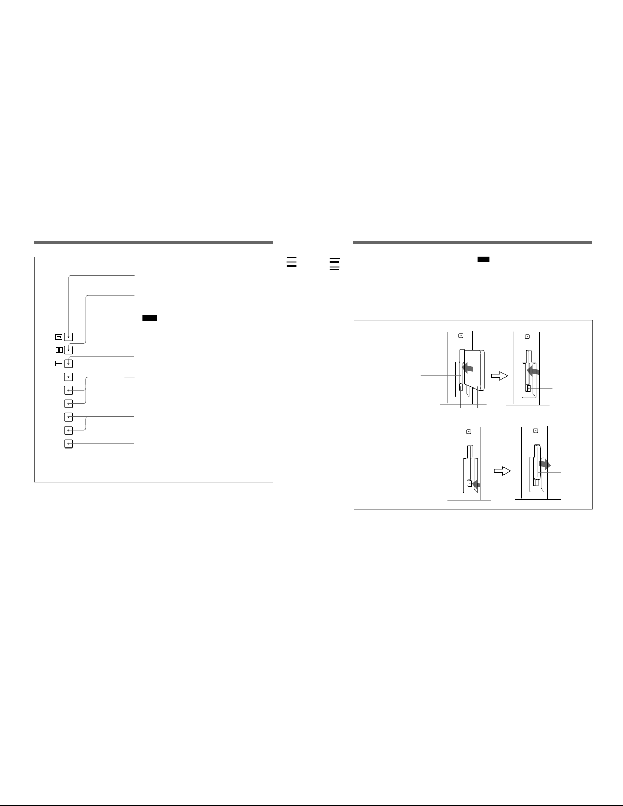
Chapter 1 Overview
To insert the BKM-12Y Monitor Memory Card
EJECT button
Monitor memory card insertion slot
Monitor memory card
Be careful not to let your hands
touch the connectors on the front
edge of the monitor memory card.
Push the monitor
memory card in
until the EJECT
button comes out.
To eject the BKM-12Y Monitor Memory Card
EJECT button
Press the EJECT button to eject
the monitor memory card.
Take out the
monitor memory
card.
!™ Monitor Memory Card slot
Insert the BKM-12Y Monitor Memory Card
(optional).
For information about operations on monitor memory card
data, see “Monitor Memory Card Data Operations —
MEMORY CARD menu” on page 46.
Proceed as illustrated to insert and eject the BKM-12Y
Monitor Memory Card.
!£ OPTION connector
Connector for expansion.
Location and Function of Parts
Note
Do not eject the monitor memory card while data is
being saved or loaded.

1-10
15
Chapter 1 Overview
Rear Panel
BVM-14G5U/14G5E/14G5A
2 AC IN connector
1 MAIN POWER switch
BVM-20G1U/20G1E/20G1A/14G1U/14G1E/14G1A
1 MAIN POWER switch
2 AC IN connector
(Illustration: BVM-20G1U/20G1E/20G1A)
7 ISR connector
3 Analog input/output
connectors
4 Input option slot
5 REMOTE 1 connectors
6 REMOTE 2 connector
7 ISR connector
3 Analog input/output
connectors
4 Input option slot
5 REMOTE 1 connectors
6 REMOTE 2 connector
8 CONTROL UNIT connector
16
Chapter 1 Overview
Location and Function of Parts
REMOTE 1 IN connector
REMOTE 1 OUT connector
1 MAIN POWER switch
When turned on, the monitor enters standby mode. By
setting in the SYSTEM CONFIGURATION menu, the
monitor can also be set to enter operation mode when
the MAIN POWER switch is turned on.
For information about the SYSTEM CONFIGURATION
menu, see “Setting Power-Up Conditions and Decoder (SET
UP 4) —SYSTEM CONFIGURATION Menu” on page 39.
2 AC IN connector (3-pin)
Connects the monitor to an AC power source, via the
supplied AC power cord.
3 Analog input/output connectors
RGB signals, component signals (Y/R-Y/B-Y), or
composite sync signals can be fed in the IN
connectors. The type of signal applied to each
connector is set with the INPUT CONFIGURATION
menu. The OUT connectors are used for loop-through
output of the input signal. When not using loopthrough, connect a 75-ohm terminator (not supplied) to
the OUT connectors.
Attach the cord stopper to the AC power cord, and connect it
to the plug holder so that the cord does not come loose.
Cord stopper (supplied)
AC power cord (supplied)
Plug holder
For information about the INPUT CONFIGURATION
menu, see “Setting the Input Configuration (SET UP 1)—
INPUT CONFIGURATION Menu” on page 32.
4 Input option slot
One optional decoder adaptor or input expansion
adaptor can be installed into this option slot.
5 REMOTE 1 connectors (female, D-sub 9-pin)
These are RS-485 serial interface connectors, used for
connecting two or more BVM/HDM-series monitors.
The IN and OUT connectors form a loop-through
connection.
Connect two monitors using a cable with D-sub 9-pin
plugs such as an RCC-5G (not supplied) as shown in
the figure on the next page.
Y/G connectors (BNC)
B-Y/B connectors (BNC)
R-Y/R connectors (BNC)
SYNC connectors (BNC)
IN
Y/G
OUT
IN
OUT
IN
OUT
IN
OUT
B-Y/B
R-Y/R
SYNC
ANALOG
REMOTE 1
IN
OUT

1-11
17
Chapter 1 Overview
6 REMOTE 2 connector (female, D-sub 9-pin)
Forms a pararell switch and controls the monitor
externally. The pin assignment and factory setting
function assigned to each pin are given below.
Cable with D-sub 9-pin plugs (not supplied)
Monitor 1
Monitor 2
Pin number
1
Set input signal channel 1 (numeric keypad
function)
2 Set input signal channel 2 (numeric keypad
function)
3 Select sync signal (SYNC button function)
4 Set the screen to monochrome, or set for
automatic switching based on the input signal
(MONO MODE button function)
5 Safe area on/off (SAFE AREA button
function)
6, 7 Not connected
8 Tally lamp on/off
9 Ground
Function
REMOTE 1
IN
OUT
REMOTE 1
IN
OUT
1
5
96
All pin function assignments can be changed with the
REMOTE menu.
For information about the REMOTE menu, see “Assigning
the Remote Control Functions (SET UP 2)—REMOTE
Menu” on page 35.
To switch each function between on and off or
between enable and disable, change pin connections in
the following way.
ON or enabled: Short each pin and pin 9 together.
OFF or disabled: Leave each pin open.
7 ISR (Interactive Status Reporting) connector
(female, D-sub 9-pin)
Connect to the ISR system.
8 CONTROL UNIT connector (female, D-sub 9pin)
Connects a monitor control unit such as the BKM-10R
using a cable with D-sub 9-pin plugs such as an RCC5G (not supplied).
18
Chapter 2 Menu
Menu Structure
The various functions and operating conditions of the
monitor can be set with on-screen menus. Menus
consist of multiple levels of sub menus. The overview
of the menu tree is described in “Menu Directories” on
pages 20 and 21.
Detailed information on the levels of menus is
described at the top of explanation of each menu.
When you select one item on the main menu, the level
1 menu corresponding to the selected item on the main
menu appears.
The adjustments and settings which can be made with
the menus are described below.
Note
On this monitor, menu settings displayed in blue
cannot be changed.
Display of the main menu level
A CONTROL PRESET ADJ menu
B COLOR TEMP ADJ menu
C SET UP menus
D MEMORY CARD menu
E COPY menu
F STATUS menu
G MAINTENANCE menu
H KEY PROTECT
Functions
Sets the preset values for the input signal contrast, brightness, chroma, and phase.
Sets the color temperature.
A menu group for performing monitor setup, consisting of the following.
• INPUT CONFIGURATION menu: Sets the input channel.
• REMOTE menu: Sets the remote control functionality.
• PASSWORD menu: Sets passwords for menus.
• SYSTEM CONFIGURATION menu: Sets power-up conditions and decoder.
• ON SCREEN SET menu: Sets data about the screen display.
• ALIGNMENT menu: Used to adjust the screen convergence and geometry.
• EXTEND menu: Loads the factory default data for the board installed.
Reads and writes setting and adjustment data from/into the memory card.
Operates on data in the memory card.
Copies set-up data from other connected monitors.
Displays the information about the monitor or options installed in the monitor.
Menu for maintenance (typically not used).
When set to ON, function buttons on the control unit (with the exception of menu
operation buttons) will be disable. When set to OFF, key protection is removed.
”A
”B
”C
”D
”E
”F
”G
”H
Displaying the Menus
Press the MENU button.
The menu list is displayed on the screen.
CONTROL PRESET ADJ...
MENU
COLOR TEMP ADJ...
S E T U P ...
MEMORY CARD...
COPY...
STATUS...
MAINTENANCE...
KEY PROTECT OFF
p
Menu List

1-12
19
Chapter 2 Menu
About menu numbers
For purposes of explanation in this manual, each menu
is preceded by menu numbers. The alphabet
determines the classification of Menus on the Menu
list (Main Menu), and the numbers determine the level
and the order. These menu numbers are not shown on
the screen.
The CONTROL PRESET ADJ menu
The first menu in Level 1
The third menu in Level 2
The fifth menu in Level 3
The fourth menu in Level 4
e.g. A1354
Only the menus which require explanation are
preceded by menu numbers. Thus, the menu number is
counted without menus which do not require
explanation.
ADDRESS Menu
In addition to the menus listed in the table, the
ADDRESS menu is provided. This ADDRESS menu
is used to select the monitor or the monitor group, so
that when several monitors are connected together via
serial remote ports, the control panel can select which
monitor to control.
To display or exit the ADDRESS menu, press the
ADDRESS button. The method of choosing menu
items and changing settings is the same as with the
other menus.
For information about the ADDRESS menu, see “Selecting
the Monitor to Control —ADDRESS Menu” on page 49.
20
Chapter 2 Menu
Menu Structure
Menu Directories
Menus consist of three to five levels. The Main Menus
displayed on the Menu List and Levels 1 and 2 are
shown below.
All menus including those in lower levels are shown at
the top of the explanation of each Main Menu.
... ...
...
... ... ... ...
Main Menu Level 1 Level 2...
CONTROL PRESET ADJ A MANUAL [A1]
AUTO [A2]
COPY [A3]
COLOR TEMP ADJ B MANUAL [B1]
PROBE [B2]
SET UP C INPUT CONFIGURATION [C1] FORMAT [C11]
SLOT NO
REMOTE [C2] REMOTE 1 CONFIG [C21]
REMOTE 2 CONFIG [C22]
PASSWORD [C3] ENTER PASSWORD [C31]
SYSTEM CONFIGURATION [C4] STANDBY MODE
DEFAULT CH
ON SCREEN SET [C5] CAPTION VISION [C51]
ANCILLARY DATA
CH NO [C52]
CH NAME [C52]
ALIGNMENT [C6] ROTATION (1/3)
H STATIC CONV (2/3)
H CV RC (3/3)
EXTEND MENU [C7] ENTER PASSWORD [C71]
...
...

1-13
21
Chapter 2 Menu
Main Menu Level 1 Level 2...
MEMORY CARD D SAVE [D1] NEW NAME [D11]
LOAD [D2]
DELETE [D3]
FORMAT [D4]
COPY E MONITOR ADDRESS [E1] ALL [E11]
CONTROL PRESET [E12]
COLOR TEMP [E13]
SET UP [E14]
STATUS F STATUS (1/3) [F1]
STATUS (2/3) [F2]
STATUS (3/3) [F3]
MAINTENANCE G
KEY PROTECT H
22
Chapter 2 Menu
Basic Menu Operations
Menu Operation Buttons
The menus are operated using the menu operation
buttons on the front panel.
The functions of the menu operation buttons are
described below.
1 Numeric keypad
2 Ent button
3 Del button
4 PHASE knob
5 MENU button
6 UP/DOWN buttons
7 ENTER button
Menu Operation
Follow the steps described below to display the menu
and perform the adjustment or setup you wish.
1
Press the MENU button 5.
The Menu List is displayed.
2
Using the UP/DOWN buttons 6 or PHASE knob
4, move the cursor to the desired item. (Example:
select the SET UP menu by pressing the DOWN
button.)
3
Press the ENTER button 7.
The Level 1 of the selected menu is displayed.
Cursor
Menu List
Button Function
5MENU button Displays the Menus. Goes back to the
menu of the upper level (on the Main
Menu, goes back to the normal
picture).
6UP button Moves the cursor upward. In setting
mode, increases the setting and
adjustment values.
6DOWN button Moves the cursor downward. In setting
mode, decreases the setting and
adjustment values.
4PHASE knob By turning this knob clockwise, the
cursor moves upward. In setting mode,
increases the setting and adjustment
values (has the same function as UP
button).
By turning this knob counterclockwise,
the cursor moves downward. In setting
mode, decreases the setting and
adjustment values (has the same
function as DOWN button).
2Ent button Executes the items selected and
7ENTER button settings.
3Del button Deletes the values and characters
entered.
1Numeric keypad Enters the numerical values.
INPUT
1
2
3
Del
4
5
6
0
7
8
9
Ent
UP MENU
DOWN
ENTER
CONTROL PRESET ADJ...
MENU
COLOR TEMP ADJ...
S E T U P ...
MEMORY CARD...
COPY...
STATUS...
MAINTENANCE...
KEY PROTECT OFF
p
INPUT CONFIGURATION...
SET UP
REMOTE...
PASSWORD...
SYSTEM CONFIGURATION...
ON SCREEN SET...
ALIGNMENT...
EXTEND MENU
p
...
PHASE

1-14
23
Chapter 2 Menu
4
Repeat steps 2 and 3 until the desired menu is
displayed.
For more information about setting and
adjustments, see the next page.
To abort menu operation
Press the MENU button. The menu of the upper level
is displayed.
The setting or adjustment being performed is canceled,
and data loading or saving is aborted.
If “NG” or “ERROR” appears during menu operation
Press the MENU button to return to the menu in use.
Choosing one of two or more selections
Selecting in yellow text
1
Using the UP/DOWN buttons or PHASE knob,
move the cursor to the desired item and press the
ENTER or Ent button.
The selected item is displayed in yellow text and
set to setting mode.
2
Using the UP/DOWN buttons or PHASE knob,
change the setting.
3
Press the ENTER or Ent button.
The setting is confirmed (The item is displayed in
white text again).
Selecting from the setting list
1
Using the UP/DOWN buttons or PHASE knob, move
the cursor to the desired item in the setting list.
2
Press the ENTER button.
The display returns to the menu of the upper level,
and the selected setting is executed.
Entering a numerical value
1
Using the UP/DOWN buttons or PHASE knob,
move the cursor to the desired item and press the
ENTER or Ent button.
The selected item is displayed in yellow text and
set to setting mode.
Enters
numerical
values.
[ ↓ ] indicates that
the menu
continues onto
next page.
[ ↑ ] indicates that
the menu is
continued from
previous page.
Selects from
various options.
Indicates that
this item has
sub-list. Thus,
you can go to
the lower level.
(Continued)
SCREEN MODE
4:3-NORM
4:3-UNDR
16:9-NORM
16:9-UNDR
p
E ...
APERTURE OFF
VALUE 100
10CH
INPUT CONFIGURATION ↑↓
FORMAT... NTSC-7 .5
SLOT NO 2
INPUT NO 1
YC S EP 3LINES COMB
SYNC M ODE INT
SCREEN MODE... 4:3-NORM
SAFE AREA OFF
SCAL 80%
p
SCALE...
APERTURE OFF
VALUE 100
10CH
INPUT CONFIGURATION ↑↓
FORMAT... NTSC-7 .5
SLOT NO 2
INPUT NO 1
YC S EP 3LINES COMB
SYNC M ODE INT
SCREEN MODE... 4:3-NORM
SAFE AREA OFF
80%
p
SCALE...
APERTURE OFF
VALUE 085
10CH
INPUT CONFIGURATION ↑↓
FORMAT... NTSC-7 .5
SLOT NO 2
INPUT NO 1
YC S EP 3LINES COMB
SYNC M ODE INT
SCREEN MODE... 4:3-NORM
SAFE AREA OFF
80%
p
24
Chapter 2 Menu
Basic Menu Operations
2
Set the value in one of the following three ways:
• Enter the value directly using the numeric keypad
• Select the value using the UP/DOWN buttons
• Select the value using the PHASE knob
3
Press the ENTER button.
The setting is confirmed (The item is displayed in
white text again).
Entering characters
1
Display the setting menu and set the cursor to
NEW NAME using the UP/DOWN buttons or
PHASE knob.
2
Press the ENTER button.
“?” is displayed in yellow. The “?” indicates the
position where character input is possible.
3
Select the character you wish to enter using the
UP/DOWN buttons or PHASE knob. When you
press the UP button, or turn the PHASE knob
clockwise, the characters and symbols appear in
the order shown below.
A, B, .............Y, Z, 0, 1, ...............8, 9, ( , ), :, ;, .,
-, +, /, &, CH, (space), ?
If you press the DOWN button or turn the PHASE
knob to the left, the characters and symbols appear
in the reverse order described above.
4
Press the ENTER button.
The selected character is entered.
5
Repeat steps 3 and 4 until all the characters are
entered, then press the ENTER button.
The selected characters are confirmed, and the
display returns to the menu of the previous level.
To correct the entered character
Press the Del button on the numeric keypad. The
character on the left side of the “?”(in yellow) is
deleted.
CHANNEL NAME
PROG
EDIT
CAM
VTR
NEW NAME
p
CHANNEL NAME
PROG
EDIT
CAM
VTR
NEW NAME
?
p
CHANNEL NAME
PROG
EDIT
CAM
VTR
NEW NAME
C?
p

1-15
25
Chapter 2 Menu
Preset Adjustment of the Picture Level Control
Knobs — CONTROL PRESET ADJ Menu
The preliminary adjustment of contrast, brightness,
chroma, and phase are carried out with the CONTROL
PRESET ADJ menu to set the preset values to the
knobs for the above-mentioned adjustments.
Preset values can be set in the following ways:
•Adjustment with the MANUAL knobs
•Automatic adjustment (An external color bar signal is
necessary.)
•Copying data from other BVM-series monitors that
have been connected via the serial remote connector,
or from data stored in monitor memory cards.
This section explains the setting lists displayed in the
menu.
How to read the setting lists
•For purposes of explanation, each setting list is
preceded by a menu number. These numbers are not
displayed on the screen.
For more information about the menu number, see “About
menu numbers” on page 19.
•The arrow mark (÷) refers you to another setting list
that appears after you make the setting, or to an
operation that is carried out as a result of the setting.
When there is no arrow mark, the menu does not have
any sub-list.
[A] CONTROL PRESET ADJ menu
Select the setting method.
MANUAL: Set with the MANUAL knobs. ÷[A1]
AUTO: Set by automatic adjustment. ÷[A2]
COPY: Copy data from elsewhere. ÷[A3]
Overview
[A1] MANUAL menu
Adjust values by turning the CHROMA, BRIGHT,
CONTRAST and/or PHASE knobs. After the
adjustment, press the ENTER button to confirm the
adjusted values.
PHASE: xxxx
CHROMA: xxxx
BRIGHT: xxxx
CONTRAST: xxxx
When you want to erase characters from the screen
while adjusting manually
Press the [F1] button. The characters disappear. To
display characters, press the [F1] button again.
To reset the setting to the default
Press the corresponding MANUAL button. The
adjusted value is reset to 1000 (default).
Setting Lists in the CONTROL PRESET ADJ Menu
Structure of the CONTROL PRESET ADJ Menu
[A]
Level 1 Level 2
MANUAL [A1] FULL FIELD CB 100
AUTO [A2] FF CB 75 (WHITE 100)
SMPTE CB
EIA CB
COPY [A3] OTHER MONITOR [A31]
MEMORY CARD [A32]
26
Chapter 2 Menu
[A2] AUTO menu
Select the color bar signal to be used for automatic
adjustment. ÷Adjustment is carried out.
FULL FIELD CB 100: 100% full-field color bar
FF CB 75 (WHITE 100): 75% full-field color bar
(with 100 % white signal)
SMPTE CB: SMPTE standard color bar
EIA CB: EIA standard color
[A3] COPY menu
Select the source to be copied from.
OTHER MONITOR: Copy data from another
monitor. ÷[A31]
MEMORY CARD: Copy data from a memory card.
÷[A32]
[A31] OTHER MONITOR menu
Input the address of the monitor from which the data
will be copied. ÷ Copy is carried out.
MONITOR ADDRESS: Input the address.
[A32] MEMORY CARD menu
Select the file name. ÷ Copy is carried out.
FILE NAME: Select the file name.
Preset Adjustment of the Picture Level Control Knobs — CONTROL
PRESET ADJ Menu

1-16
27
Chapter 2 Menu
Overview
The color temperature is adjusted with the COLOR
TEMP ADJ menu. The color temperature can be set to
one of STD, COL1 or COL 2 for each channel.
Use the factory setting value or the adjusted value as
an original values to shorten the adjustment time.
Color temperature adjustment can be made in the
following three ways:
•Knob adjustment
Adjust the color temperature with the bias and gain
knobs manually.
•Automatic adjustment using a probe
You can use the following probes for automatic
adjustment of color temperature. Except for the Sony
BKM-14L, a cable is required to connect the color
analyzer to the monitor.
Adjusting the Color Temperature — COLOR TEMP
ADJ Menu
For more information about the cable specification required
and about the connection, see “Connection Cable
Specifications for Color Temperature Probes” on page
54.
•Copying other data
Copying data from other BVM-series monitors that
have been connected via the serial remote connector,
or from data stored in monitor memory cards.
Manufacturer Probe Model Name
SONY BKM-14L (no cable required)
GRASEBY SLS 9400
MINOLTA CA-100
PHILIPS
PM 5639
THOMA TF6
28
Chapter 2 Menu
Adjusting the Color Temperature — COLOR TEMP ADJ Menu
Structure of the COLOR TEMP ADJ Menu [B]
Level 1 Level 2 Level 3 Level 4 Level 5
MANUAL [B1]
ADJUST [B211] START [B2111] SET PROBE
PROBE [B2] SONY BKM-14L [B21] ANALYZE [B212] X ON CRT
GRASEBY SLS9400 Y
MINOLTA CA-100 LOWLIGHT (20 IRE)
PHILIPS PM5639 HIGHLIGHT (100IRE)
THOMA TF6 START [B213] D65
X D93
Y SET PROBE
LOWLIGHT (20 IRE) ON THIS CRT [B2121]
HIGHLIGHT (100IRE)
D65 SET PROBE
D93 ON CRT
COPY [B3] OTHER VALUE [B31] STD
COL1
COL2
D65
D93
OTHER
MONITOR [B32] MONITOR
ADDRESS [B321] STD
COL1
COL2
MEMORY CARD [B33] FILE NAME [B331] STD
COL1
COL2
TRIM [B4] ADJUST
TRIM
SIGNAL
The lower levels of GRASEBY SLS9400, MINOLTA CA-100, PHILIPS PM5639 and THOMA TF6 are the
same as [B213] in level 3 and lower than that.

1-17
29
Chapter 2 Menu
Setting Lists in the COLOR TEMP ADJ Menu
This section explains the setting lists displayed in the
menu.
How to read the setting lists
•For purposes of explanation, each setting list is
preceded by a menu number. These numbers are not
displayed on the screen.
For more information about the menu number, see “About
menu numbers” on page 19.
•The arrow mark (÷) refers you to another setting list
that appears after you make the setting, or to an
operation that is carried out as a result of the setting.
When there is no arrow mark, the menu does not have
any sub-list.
[B] COLOR TEMP ADJ menu (STD/COL1/
COL2)
Select the adjustment method.
MANUAL: Set with the MANUAL knob. ÷[B1]
PROBE: Set using a probe. ÷[B2]
COPY: Copy data from elsewhere. ÷[B3]
TRIM: Perform fine adjustments after setting the
color temperature. ÷[B4]
[B1] MANUAL menu (STD/COL1/COL2)
Adjust the gain and bias manually.
ADJUST: Adjust the gain and bias. To shift between
gain adjustment and bias adjustment, press UP/
DOWN buttons. Use appropriate knobs in each
adjustment as described below. After the
adjustment, press the ENTER button to confirm the
adjusted values.
RED: CONTRAST knob (Adjust the R gain or
bias with the CONTRAST knob.)
GREEN: BRIGHT knob (Adjust the G gain or
bias with the BRIGHT knob.)
BLUE: CHROMA knob (Adjust the B gain or bias
with the CHROMA knob.)
LUMINANCE: PHASE knob (Adjust luminance
with the PHASE knob.)
To reset RED/GREEN/BLUE to the value
before adjustment
When you are adjusting the gain or bias using the
MANUAL adjustment knobs, you can reset the
setting to the one before adjustment by pressing the
corresponding MANUAL button.
To reset all of settings at the same time, press the
PHASE button.
Note
You cannot reset the setting after you press the
ENTER button.
ORIGINAL VALUE: Set the initial value.
STD: Use common data (factory setting: D93).
COL1: Use common data (factory setting: D65).
COL2: Use common data (factory setting: D93).
SIGNAL: Select the white signal to be used for
adjustment.
INT: Use an internal signal. Simultaneously with
the adjustment of the gain and bias, the 100
IRE and 20 IRE signals are automatically
switched.
EXT: Use an external input signal. When adjusting
the gain and bias, input the proper signal.
To access the MANUAL menu directly
When the [F2] button is assigned as the short-cut
key to the MANUAL menu, you can directly
access the MANUAL menu that corresponds to the
color temperature setting set to the image on the
screen.
For details of how to assign the short-cut key, see
“Setting the Power-Up Conditions (SET UP 4) SYSTEM CONFIGURATION Menu” on page 39.
[B2] PROBE menu(STD/COL1/COL2)
Select the probe for color temperature adjustment.
SONY BKM-14L...: Use the BKM-14L.
÷[B21]
GRASEBY SLS 9400...: Use the SLS 9400.
÷[B213]
MINOLTA CA-100...: Use the CA-100. ÷[B213]
PHILIPS PM 5639...: Use the PM 5639.
÷[B213]
THOMA TF6...: Use the TF6. ÷[B213]
•If you cannot execute an ADJUST or ANALYZE
menu operation when using the Sony BKM-14L
probe, try again after disconnecting and reconnecting
the probe.
•When using the Thoma TF6 probe, set the TF6
PRINT menu to off.
30
Chapter 2 Menu
Adjusting the Color Temperature — COLOR TEMP ADJ Menu
[B13] COPY SOURCE menu (STD/COL1/COL2)
Select the adjustment method and the source to be
copied from.
OTHER VALUE: Copy data from one of STD, COL
1 or COL 2. ÷[B31]
OTHER MONITOR: Copy data from another
monitor. ÷[B32]
MEMORY CARD: Copy data from a memory card.
÷[B33]
[B4] TRIM menu (STD/COL1/COL2)
Trim the original setting by selecting ADJUST.
ADJUST: Adjust the gain and bias. To shift between
gain adjustment and bias adjustment, press UP/
DOWN buttons. Use appropriate knobs in each
adjustment as described below. After the
adjustment, press the ENTER button to confirm the
adjusted values.
RED: CONTRAST knob (Adjust the R gain or
bias with the CONTRAST knob.)
GREEN: BRIGHT knob (Adjust the G gain or
bias with the BRIGHT knob.)
BLUE: CHROMA knob (Adjust the B gain or bias
with the CHROMA knob.)
LUMINANCE: PHASE knob (Adjust luminance
with the PHASE knob.)
To reset RED/GREEN/BLUE to the value
before adjustment
When you are adjusting the gain or bias using the
MANUAL adjustment knobs, you can reset the
setting to the one before adjustment by pressing the
corresponding MANUAL button.
To reset all of settings at the same time, press the
PHASE button.
TRIM: Select whether to add the fine adjustment to
the original setting (gain and bias set in MANUAL
menu [B1]).
APPLY: Adds the fine adjustment to the original
setting.
When APPLY is selected, “XX/TRIM”
(XX: the selected color temperature among
STD, COL 1 or COL 2) appears on the left
top on the COLOR TEMP ADJ menu.
NOT APPLY: Reset the setting to the original
setting (gain and bias set in MANUAL menu
[B1]).
SIGNAL: Select the white signal to be used for
adjustment.
INT: Use an internal signal. Simultaneously with
the adjustment of the gain and bias, the 100
IRE and 20 IRE signals are automatically
switched.
EXT: Use an external input signal. When adjusting
the gain and bias, input the proper signal.
Note
Even if NOT APPLY of the TRIM item is selected,
pressing the ENTER button to confirm the adjusted
values results in that APPLY will be selected.
[B21] PROBE menu (STD/COL1/COL2)
Select the BKM-14L operation.
ADJUST: Perform automatic color temperature
adjustment. ÷[B211]
ANALYZE: Display readout values on the screen.
÷[B212]
[B31] OTHER VALUE menu (STD/COL1/
COL2)
Select STD, COL1,or COL2. ÷ Copy is carried out.
STD: Copy common data (factory setting: D93).
COL1: Copy common data (factory setting: D65).
COL2: Copy common data (factory setting: D93).
D65: Copy the color temperature of D65.
D93: Copy the color temperature of D93.
[B32] OTHER MONITOR menu (STD/COL1/
COL2)
Specify the address number of the monitor.
MONITOR ADDRESS: Input the address number of
the monitor from which the data will be copied.
÷[B321]
[B33] MEMORY CARD menu
Select the file name. ÷[B331]
FILE NAME: Select the file name.

1-18
31
Chapter 2 Menu
[B211] ADJUST menu (STD/COL1/COL2)
To start adjustment, proceed as follows.
When you use the previously adjusted values for
adjustment, you can make start adjustment by selecting
START without perform operations step (1) and step
(2).
(1) Select either D65 or D93.
Rather than selecting D65 or D93, you may instead
enter the values of the CIE 1931 color system x
and y coordinates.
(2) Enter values for LOWLIGHT and HIGHLIGHT.
(3) Select START.
START: Start adjustment. ÷[B2111]
X: Enter the x coordinate.
Y: Enter the y coordinate.
LOW LIGHT (20IRE): Enter the luminance (cd/m
2
)
for low light.
HIGH LIGHT (100IRE): Enter the luminance (cd/
m
2
) for high light.
D65: Use D65 setting.
D93: Use D93 setting.
[B212] ANALYZE menu (STD/COL1/COL2)
The following message appears. Perform operation
according to the message to enable the BKM-14L to
read the color system and luminace value.
SET PROBE ON THIS CRT
PRESS ENTER
Attach the BKM-14L on the center of the CRT and
press the ENTER button. ÷[B2121]
Once the BKM-14L has carried out calibration, the
BKM-14L can start analyze the monitor’s
performance.
[B321] MONITOR ADDRESS menu (STD/COL1/
COL2)
Select STD, COL1 or COL2. ÷ Copy is carried out.
STD: Copy common data (factory setting: D93).
COL1: Copy common data (factory setting: D65).
COL2: Copy common data (factory setting: D93).
[B331] FILE NAME menu (STD/COL1/COL2)
Select STD, COL1, or COL2 of the memory card data.
÷ Copy is carried out.
STD: Copy common data (factory setting: D93).
COL1: Copy common data (factory setting: D65).
COL2: Copy common data (factory setting: D93).
[B2111] COLOR TEMP ADJ menu
(STD/COL1/COL2)
The following message appears. Perform operation
according to the message to start adjustment.
SET PROBE ON CRT
PRESS ENTER
Adjustment starts when the probe is placed against the
center of the screen and the ENTER button is pressed.
[B2121] ANALYZE menu
(STD/COL1/COL2)
Display color temperature and luminance readout
values from the BKM-14L.
X: xxxx: Display the x coordiate of the color system.
Y: xxxx: Display the y coordiate of the color system.
L: xxxx: Display the luminance value.
32
Chapter 2 Menu
Setting the Input Configuration (SET UP 1) —
INPUT CONFIGURATION Menu
Data pertaining to the input signals are set with the
INPUT CONFIGURATION menu.
When a channel number (1 to 90) is entered with the
numeric keypad, it is then possible to set which input
connector on the rear panel will be assigned to that
channel number, and select the type of signal that will
be connected. The channel numbers from 91 to 99 are
assigned to internal signals.
091: PLUGE signal (Picture Line Up Generating
Equipment)
092: 20% gray signal
093: 100% white signal
094: five-step gray scale signal
095: cross hatch signal
096: cross hatch signal
097: dot signal
098: cross hatch signal
099: 0% black signal
Assigning slot and connector numbers
Set which input connector on which slot will be
assigned to the current channel. The slots are
numbered from the left, as seen when facing the rear
panel, with the REMOTE connectors slot being
number 1, the input option slots number 2, and the
analog input connectors slot being number 6. The
connectors are numbered 1 to 6 (from the top) for the
slot.
Assigning the signal type and format
The signal type and format which can be assigned to
each channel number vary, depending on what
adaptors (not supplied) are installed in the rear panel.
Overview
Structure of the INPUT CONFIGURATION Menu
[C1]
Level 1 Level 2 Level 3 Level 4
INPUT CONFIGURATION [C1] FORMAT [C11] COMPOSITE [C111] NTSC
REMOTE [C2] SLOT NO YC [C112] PAL
PASSWORD [C3] INPUT NO COMPONENT [C113] PAL-M
SYSTEM CONFIGURATION [C4] YC SEP [C12] SDI [C114] SECAM
ON SCREEN SET [C5] SYNC MODE AUTO
ALIGNMENT [C6] SCREEN MODE [C13] 4:3 NORM NTSC
EXTEND MENU [C7] SAFE AREA 4:3 - UNDR PAL
SCALE [C14] 16:9- NORM PAL-M
APERTURE 16:9 UNDR AUTO
VALUE 80
FILTER 90 YUV SMPTE/EBU-N10
CHANNEL NAME [C15] 100
YUV BETACAM
COLOR TEMP 16:9 - 80 RGB
H PHASE 16:9 - 90 NTSC
SAD H POSITION 16:9 - 100 PAL
COPY [C16] 4 : 3 - 80 4 : 2 : 2
4 : 3 - 90 AUTO
4 : 3 - 100
PROG
EDIT
CAM
VTR
NEW NAME
OTHER CH
OTHER MONITOR [C161]
MONITOR ADDRESS
MEMORY CARD [C162]
FILE NAME

1-19
33
Chapter 2 Menu
This section explains the setting lists displayed in the
menu.
How to read the setting lists
•For purposes of explanation, each setting list is
preceded by a menu number. These numbers are not
displayed on the screen.
For more information about the menu number, see “About
menu numbers” on page 19.
•The arrow mark (÷) refers you to another setting list
that appears after you make the setting, or to an
operation that is carried out as a result of the setting.
When there is no arrow mark, the menu does not have
any sub-list.
[C1] INPUT CONFIGURATION menu (1/2)
Set input signal data for each channel.
xxCH: Current channel is indicated. To change the
channel, enter a channel number with the numeric
keypad. The settings below will be stored as
information about the signal to be connected to this
channel.
FORMAT: Select the input signal type. ÷[C11]
SLOT NO: Enter the slot number.
INPUT NO: Enter the input connector number.
YC SEP: Select Y/C separation filter. ÷[C12]
SYNC MODE: Select the sync signal.
INT: Use an internal sync signal.
EXT: Use an external sync signal.
SCREEN MODE: Select the scan size. ÷[C13]
SAFE AREA: Choose whether or not to display the
safe area (OFF or ON).
SAFE AREA SCALE: Select the modes for safe area.
÷[C14]
APERTURE: Choose whether to use aperture
adjustment or not (OFF or ON).
APERTURE VALUE: Enter the aperture adjustment
value (0 to 200).
[C1] INPUT CONFIGURATION menu (2/2)
Set input signal data for each channel.
xxCH: Current channel is indicated. To change the
channel, enter a channel number with the numeric
keypad. The settings below will be stored as
information about the signal to be connected to this
channel.
FILTER: Switch the filter operation (OFF or ON)
when the monochrome display is selected.
CHANNEL NAME: Give the channel a name.
÷ [C15]
Setting Lists in the INPUT CONFIGURATION Menu
COLOR TEMP: Set the color temperature. Select
STD, COL1 or COL2.
STD: Use common data (factory setting: D93).
COL1: Use common data (factory setting: D65).
COL2: Use common data (factory setting: D93).
H PHASE: Set the horizontal picture position (–128 to
+127).
SAD H POSITION: Adjust the horizontal display
position of the safety area (–128 to +127).
COPY: Select a method for copying data from
elsewhere. ÷[C16]
Note
For H PHASE and SAD H POSITION data, if values
above or below the allowable range are entered, the
monitor will not operate correctly.
[C11] FORMAT menu (xxCH)
Select the signal format.
COMPOSITE: Composite signal ÷ [C111]
YC: Y/C signal ÷ [C112]
COMPONENT: Component or RGB signal
÷ [C113]
SDI: Serial digital signal ÷ [C114]
Note
If there is no input connector or decoder corresponding
to a format, that format will not be selectable (the
cursor will skip over that item).
[C12] YC SEP menu
Select a Y/C separation filter.
TRAP/BPF: Select TRAP/BPF filter.
2 LINES COMB: Select 2 LINES COMB filter.
3 LINES COMB: Select 3 LINES COMB filter.
[C13] SCREEN MODE menu (xxCH)
Select the scan size.
4:3-NORM: Overscanned 4:3 aspect ratio. (when not
using 16:9 mask)
4:3-UNDR: Underscanned 4:3 aspect ratio. (when not
using 16:9 mask)
16:9-NORM: Overscanned 16:9 aspect ratio.
16:9-UNDR: Underscanned 16:9 aspect ratio.
[C14] SAFE AREA SCALE
Select the setting for each items of SAFE AREA
setting list.
80: Displays a 80% safe area in 4:3 screen.
90: Displays a 90% safe area in 4:3 screen.
100: Displays an 100% safe area in 4:3 screen.
16:9-80: Displays a 80% of 16:9 aspect ratio safe area
in 4:3 screen.
34
Chapter 2 Menu
16:9-90: Displays a 90% s16:9 aspect ratio safe area in
4:3 screen.
16:9-100: Displays an 100% 16:9 aspect ratio safe
area in 4:3 screen.
4:3-80: Displays a 80% 4:3 aspect ratio safe area in
16:9 screen.
4:3-90: Displays a 90% 4:3 aspect ratio safe area in
16:9 screen.
4:3-100: Displays an 100% 4:3 aspect ratio safe area
in 16:9 screen.
[C15] CHANNEL NAME menu (xxCH)
Give the channel a name. Select a preset name, or
enter a new one.
PROG: Program signal.
EDIT: Signal from an editor.
CAM: Camera signal.
VTR: Signal from a VTR.
NEW NAME: Enter a new name. (Up to 20 characters
can be entered and up to six characters from the
head of the name are displayed in the INPUT
CONFIGURATION menu.)
[C16] COPY menu (xxCH)
Select the source to be copied from.
OTHER CH: Copy data from another channel. Enter
the channel number.
When the input channel number is deleted with the
Del button, the number “1” appears instead.
Restore the previous setting by pressing the
MENU button, then re-enter the channel number.
(Setting with the UP/DOWN buttons or PHASE
knob is possible.)
OTHER MONITOR: Copy data from another
monitor. ÷[C161]
MEMORY CARD: Copy data from a memory card.
÷[C162]
[C111] COMPOSITE menu (xxCH)
Select the format of a composite signal.
NTSC: SETUP 7.5 or 0.
PAL: S (simple) or D (delay)
PAL-M: S (simple) or D (delay)
SECAM
AUTO: The format of the input signal is detected and
switched automatically.
1)
1) It will take a few seconds to detect the format of an input
signal when AUTO is selected. It is recommended that a
particular format be selected if it is determined.
Notes
•Even when selecting AUTO, also select the NTSC,
PAL, or PAL-M format.
•If there is no input connector or decoder
corresponding to a format, that format will not be
selectable (the cursor will skip over that entry).
[C112] Y/C menu (xxCH)
Select the format of a Y/C signal.
NTSC: SETUP 7.5 or 0.
PAL: S (simple) or D (delay)
PAL-M: S (simple) or D (delay)
AUTO: The format of the input signal is detected and
switched automatically.
1)
1) It will take a few seconds to detect the format of an input
signal when AUTO is selected. It is recommended that a
particular format be selected if it is determined.
Notes
•Even when selecting AUTO, also select the NTSC,
PAL, or PAL-M format.
•If there is no input connector or decoder
corresponding to a format, that format will not be
selectable (the cursor will skip over that entry).
[C113] COMPONENT menu (xxCH)
Select the component signal format, or RGB.
YUV SMPTE/EBU-N10
YUV BETACAM: SETUP 7.5 or 0.
RGB
[C114] SDI menu (xxCH)
Select the format of the serial digital signal
1)
.
NTSC: SETUP 7.5 or 0.
PAL: S (simple) or D (delay)
4:2:2
AUTO: The format of the input signal is detected and
switched automatically.
1)
1) • It will take a few seconds to detect the format of an
input signal when AUTO is selected. It is
recommended that a particular format be selected if it
is determined.
• If the serial digital signal is not properly displayed in
SDI AUTO mode, re-enter the channel number.
[C161] OTHER MONITOR menu (xxCH)
Enter the address number of the source monitor.
÷ Copy is carried out.
MONITOR ADDRESS: Enter the address number of
the monitor from which to copy data.
[C162] MEMORY CARD menu (xx CH)
Select the file name.÷ Copy is carried out.
FILE NAME: Select the file name.
Setting the Input Configuration (SET UP 1) — INPUT CONFIGURATION Menu

1-20
35
Chapter 2 Menu
Assigning the Remote Control Functions
(SET UP 2) — REMOTE Menu
The remote control functions are set with the
REMOTE menu. With this monitor, both serial remote
control (REMOTE 1) and parallel remote control
(REMOTE 2) are possible. It is possible to
simultaneously use the REMOTE 1, and REMOTE 2
provided with BKM-10R/11R, the integrated control
unit monitors HDM-14E5U, BVM-14E5U/14E5E/
14F5U/14F5E/14G5U/14G5E/14G5A, for control, but
commands from REMOTE 2 have priority. Therefore,
it is impossible for the control panel or REMOTE 1 to
change items set by REMOTE 2.
There is no priority order between commands from
REMOTE 1 and the BKM-10R/11R control panel; it is
possible to set APERTURE to ON from REMOTE 1
and then set it to OFF with a control panel operation.
About monitor address and group numbers
The monitor control units BKM-10R/11R or control
unit monitors HDM-14E5U, BVM-14E5U/14E5E/
14F5U/14F5E/14G5U/14G5E/14G5A are able to
control up to 32 monitors connected via serial remote
connector (using the REMOTE 1 connector). By
giving each monitor a monitor address and group
number, it is possible to control just a specific monitor
or monitor group.
With the REMOTE menu, each monitor can be set
with a monitor address and group number, between 1
and 99.
The ADDRESS menu is used to select a particular
monitor or group by entering a monitor number or
group number.
For information about the ADDRESS menu, see “Selecting
the Monitor to Control —ADDRESS Menu” on page 49.
The address number must differ from one monitor to
another. If two or more monitors have the same address
number, an operation error occurs.
Overview
Structure of the REMOTE Menu
[C2]
Level 1 Level 2 Level 3
INPUT CONFIGURATION [C1] MONITOR ADDRESS
REMOTE [C2] REMOTE 1 CONFIG [C21] GROUP ADDRESS
PASSWORD [C3] REMOTE MODE [C211]
SYSTEM CONFIGURATION [C4] REMOTE 2 CONFIG [C22] 1 PIN [C221]
ON SCREEN SET [C5] REMOTE 2 2 PIN
ALIGNMENT [C6] 3 PIN
EXTEND MENU [C7] 4 PIN
5 PIN
6 PIN
7 PIN
8 PIN
Setting Lists of the REMOTE Menu
This section explains the setting lists displayed in the
menu.
How to read the setting lists
•For purposes of explanation, each setting list is
preceded by a menu number. These numbers are not
displayed on the screen.
For more information about the menu number, see “About
menu numbers” on page 19.
•The arrow mark (÷) refers you to another setting list
that appears after you make the setting, or to an
operation that is carried out as a result of the setting.
When there is no arrow mark, the menu does not have
any sub-list.
36
Chapter 2 Menu
[C2] REMOTE menu
Select the type of remote control.
REMOTE 1 CONFIG: Set the address and group
number of the monitor controlled via the
REMOTE 1 (serial remote control) connector.
÷[C21]
REMOTE 2 CONFIG: Set the pin assignments for
the REMOTE 2 (parallel remote control)
connector. ÷[C22]
REMOTE 2: Select whether parallel remote control
will be used or not (ON or OFF).
[C21] REMOTE 1 CONFIG menu
Set the monitor address and group number.
MONITOR ADDRESS: Enter a number.
GROUP ADDRESS: Enter a number.
REMOTE MODE: Select the remote mode.
÷[C211]
[C22] REMOTE 2 CONFIG
Select the REMOTE 2 connector pins for which you
want to change the function. The factory settings for
each pin are given below. ÷[C221]
1 PIN: CH01
2 PIN: CH02
3 PIN: EXT SYNC
4 PIN: MONO
5 PIN: SAFE AREA ON
6 PIN: unused
7 PIN: unused
8 PIN: TALLY
[C211] REMOTE MODE menu
Select a remote mode according to the type of
monitors connected through the REMOTE 1
connector.
When only Sony BVM-xxE/F/G or HDM-xxE series
monitors are connected: set REMOTE MODE to
0.
When a Sony BVM-xx11/16 series monitor or a
Sony PVM monitor (with BKM-103 Serial
Remote Interface Kit installed) is connected: set
REMOTE MODE to 1 and enter a number over 64
as the MONITOR ADDRESS for each connected
Sony BVM-xxE/F/G and HDM-xxE series
monitor.
[C221] 1-8 PIN (1/2) menu
Assign a function to the selected pin.
CH: Select a channel number. Enter the desired
channel number with the numeric keypad.
----: Set to unused.
UNDER SCAN: Set underscan on or off.
16:9: Set a 16:9 aspect ratio on or off.
H DELAY: Set the horizontal sync display on or off.
V DELAY: Set the vertical sync display on or off.
EXT SYNC: Set the synchronization to external sync
signals enabled or disabled.
APERTURE: Set the correction of frequency
characteristics enabled or disabled.
MONO: Set monochrome display on or off.
1-8 PIN (2/2) menu
Assign a function to the selected pin.
BLUE ONLY: Set the blue signal pictures display
(monochrome) on or off.
R OFF: Set cutting red beams enabled or disabled.
G OFF: Set cutting green beams enabled or disabled.
B OFF: Set cutting blue beams enabled or disabled.
SAFE AREA ON: Set the safe area display on or off.
CAPTION VISION: Set Caption Vision on or off.
TALLY: Set tally signals on or off.
DEGAUSS: Set degaussing on or off.
POWER OFF: Set the monitor power on or off.
Assigning the Remote Control Functions (SET UP 2) REMOTE Menu

1-21
37
Chapter 2 Menu
A four-digit password can be specified and applied to
desired menu options to prohibit the menu settings
from being changed without permission. The password
is set with the PASSWORD menu.
A password is always assigned to the PASSWORD
menu (factory setting: 9999).
A password for a service man can be created with the
MAINTENANCE menu.
Use of the password
The message “ENTER PASSWORD” is displayed
when an attempt is made to select a menu item for
which the password has been applied. Then, enter the
password using numeric keypad.
If the password is not entered correctly
If an incorrect password is entered, the display returns
to the menu of the previous level.
Setting the Password (SET UP 3) — PASSWORD
Menu
Overview
Structure of the PASSWORD Menu
[C3]
Level 1 Level 2 Level 3 Level 4 Level 5
INPUT CONFIGURATION [C1]
REMOTE [C2]
PASSWORD [C3] ENTER [C31] CHANGE
SYSTEM CONFIGURATION [C4] PASSWORD PASSWORD [C311] ENTER RE-ENTER
ON SCREEN SET [C5] PASSWORD [C3111] PASSWORD
ALIGNMENT [C6]
EXTEND MENU [C7] APPLY CONTROL PRESET ADJ
PASSWORD [C312] COLOR TEMP ADJ
SET UP
MEMORY CARD
COPY
KEY PROTECT
Setting Lists of the PASSWORD Menu
This section explains the setting lists displayed in the
menu.
How to read the setting lists
•For purposes of explanation, each setting list is
preceded by a menu number. These numbers are not
displayed on the screen.
For more information about the menu number, see “About
menu numbers” on page 19.
•The arrow mark (÷) refers you to another setting list
that appears after you make the setting, or to an
operation that is carried out as a result of the setting.
When there is no arrow mark, the menu does not
have any sub-list.
38
Chapter 2 Menu
[C31] ENTER PASSWORD menu
Enter the password for the PASSWORD menu.
Choose what action to perform with the password.
CHANGE PASSWORD: Change the password.
÷[C311]
APPLY PASSWORD: Assign the password to a
menu item. ÷[C312]
[C311] CHANGE PASSWORD menu
Change the password.
ENTER PASSWORD: Enter a new password.
÷[C3111]
[C312] APPLY PASSWORD menu
Choose whether or not to apply the password to each
menu.
CONTROL PRESET ADJ: Select YES or NO.
CONTROL TEMP ADJ: Select YES or NO.
SET UP: Select YES or NO.
MEMORY CARD: Select YES or NO.
COPY: Select YES or NO.
KEY PROTECT: Select YES or NO.
[C3111] ENTER PASSWORD menu
Create a new password.
RE-ENTER PASSWORD
Enter the new password again and press the
ENTER button. ÷ The password is required.
To change it, press the MENU button. ÷ Return
to the PASSWORD [C31].
Setting the Password (SET UP 3) — PASSWORD Menu

1-22
39
Chapter 2 Menu
Setting Power-Up Conditions and Decoder (SET UP 4) —
SYSTEM CONFIGURATION Menu
The SYSTEM CONFIGURATION menu is used for
the following settings:
•Power-up condition
This menu sets the condition of the monitor when the
MAIN POWER switch on the rear panel is switched
on.
ON: Standby mode
OFF: Operation mode
•Power-up input channel
LAST: Set the channel to the channel that was
selected at the time the power was last turned off.
CH xx: Set the channel to a specific channel number.
•Time from power-up until degauss
If several monitors are turned on at the same time and
all start degaussing at the same time, there will be a
very large current draw on the power supply for a few
moments. To prevent this, the delay time between
power-up and degaussing can be set for each monitor
independently.
•Residual subcarrier detection (when using the BKM24N/25P)
It is possible to detect residual subcarrier signals from
phase change by setting the decoder adpator’s
residual subcarrier switch on.
•Auto chroma control (ACC) (when using the BKM27T)
•Setting of the contrast and brightness after adjusting
the white balance or auto adjustment of CONTROL
PRESET.
ON: The contrast and brightness are set to the value
before adjusting.
OFF: The contrast and brightness are set to the center
value (1000) after adjusting.
•Assigning shortcut to the menu to the [F2] key
Assigns the shortcut to the MANUAL menu of the
COLOR TEMP ADJ menu to the [F2] key. This
allows you to jump directly to the MANUAL menu
corresponding to the color temperature set to the
currently displayed image (STD/COL 1/COL 2).
ON: Assigns the shortcut to the MANUAL menu of
the COLOR TEMP ADJ menu.
OFF: Does not assign the shortcut to the MANUAL
menu of the COLOR TEMP ADJ menu.
Overview
Structure of the SYSTEM CONFIGURATION Menu
[C4]
Main Menu Level 1 Level 2
SET UP C INPUT CONFIGURATION [C1]
REMOTE [C2]
PASSWORD [C3]
SYSTEM CONFIGURATION [C4] STANDBY MODE
ON SCREEN SET [C5] DEFAULT CH
ALIGNMENT [C6] DEGAUSS DELAY
EXTEND MENU [C7] RESIDUAL SC SW
ACC SW
CONT/BRT HOLD
COL TEMP SHORT-CUT
40
Chapter 2 Menu
Setting Lists of the SYSTEM
CONFIGURATION Menu
This section explains the setting lists displayed in the
menu.
How to read the setting lists
•For purposes of explanation, each setting list is
preceded by a menu number. These numbers are not
displayed on the screen.
For more information about the menu number, see “About
menu numbers” on page 19.
•The arrow mark (÷) refers you to another setting list
that appears after you make the setting, or to an
operation that is carried out as a result of the setting.
When there is no arrow mark, the menu does not have
any sub-list.
[C4] SYSTEM CONFIGURATION menu
Set each of the various items.
STANDBY MODE: Select the power-up condition
when the MAIN POWER switch is turned on (OFF
or ON).
DEFAULT CH: Select the power-up input channel
(LAST or CH xx).
DEGAUSS DELAY: Set the time between power-up
and the beginning of degaussing. Enter the desired
time (in seconds).
RESIDUAL SC SW: Switch the residual switch (OFF
or ON).
ACC SW: Switch the ACC switch (OFF or ON).
CONT/BRT HOLD: Select the contrast and
brightness settings to the center or adjusted value
after adjusting the white balance or auto
adjustment of CONTROL PRESET (OFF or ON).
COL TEMP SHORT-CUT: Assign the shortcut
function to the MANUAL menu of the COLOR
TEMP ADJ menu to [F2] key (OFF or ON).
Setting the Channel Selection Method and Power-Up Conditions (SET UP 4)
— SYSTEM CONFIGURATION Menu
 Loading...