

Sony BVE-700 Installation Manual

EDITING CONTROL UNIT
BVE-700
INSTALLATION MANUAL
1st Edition
Serial No. 10001 and Higher

! WARNING
This manual is intended for qualified service personnel only.
To reduce the risk of electric shock, fire or injury, do not perform any servicing other than that
contained in the operating instructions unless you are qualified to do so. Refer all servicing to
qualified service personnel.
! WARNUNG
Die Anleitung ist nur für qualifiziertes Fachpersonal bestimmt.
Alle Wartungsarbeiten dürfen nur von qualifiziertem Fachpersonal ausgeführt werden. Um die
Gefahr eines elektrischen Schlages, Feuergefahr und Verletzungen zu vermeiden, sind bei
Wartungsarbeiten strikt die Angaben in der Anleitung zu befolgen. Andere als die angegeben
Wartungsarbeiten dürfen nur von Personen ausgeführt werden, die eine spezielle Befähigung
dazu besitzen.
! A VERTISSEMENT
Ce manual est destiné uniquement aux personnes compétentes en charge de l’entretien. Afin
de réduire les risques de décharge électrique, d’incendie ou de blessure n’effectuer que les
réparations indiquées dans le mode d’emploi à moins d’être qualifié pour en effectuer d’autres.
Pour toute réparation faire appel à une personne compétente uniquement.
Attention-when the product is installed in Rack:
1. Prevention against overloading of branch circuit
When this product is installed in a rack and is
supplied power from an outlet on the rack, please
make sure that the rack does not overload the supply
circuit.
2. Providing protective earth
When this product is installed in a rack and is
supplied power from an outlet on the rack, please
confirm that the outlet is provided with a suitable
protective earth connection.
3. Internal air ambient temperature of the rack
When this product is installed in a rack, please make
sure that the internal air ambient temperature of the
rack is within the specified limit of this product.
4. Prevention against achieving hazardous
condition due to uneven mechanical loading
When this product is installed in a rack, please make
sure that the rack does not achieve hazardous
condition due to uneven mechanical loading.
BVE-700

Table of Contents
Manual Structure
Purpose of this manual ........................................................................................ 2 (E)
Related manuals................................................................................................... 2 (E)
Trademarks .......................................................................................................... 2 (E)
Installation
1-1. Operating Environment .........................................................................1-1 (E)
1-2. Power Supply ........................................................................................1-1 (E)
1-3. Installation Space ..................................................................................1-2 (E)
1-4. Matching Connectors and Cables..........................................................1-4 (E)
1-5. Input/Output Signals of Connectors......................................................1-5 (E)
1-6. Switch Settings on Boards and LED Description .................................1-8 (E)
1-7. Rack Mounting....................................................................................1-11 (E)
1-8. Installing the BKE-701 .......................................................................1-12 (E)
BVE-700
1 (E)

Purpose of this manual
Related manuals
Manual Structure
This manual is the installation manual of Editing Control Unit BVE-700.
This manual is intended for use by trained system and service engineers, and
describes the information on installing the BVE-700.
Beside this Installation Manual, the following manuals are available for the unit.
..
. User’s Guide (Supplied with BVE-700)
..
This manual describes the application and operation of the unit.
..
. Operation Manual (Supplied with BVE-700)
..
This manual describes the overview, system connection examples, and specifications of the unit.
..
. BKE-701 Installation Manual (Supplied with BKE-701)
..
This manual describes the information related to the installation of the unit.
Trademarks
..
. BVE-700/BKE-701 Maintenance Manual (Available on request)
..
This manual describes the information that premise the service of BVE-700/BKE701 based on components replaced.
Trademarks and registered trademarks used in this manual are follows.
.
Windows is a registered trademark of Microsoft Corporation.
. IBM is a registered trademark of International Business Machine, Inc.
. Ethernet is a registered trademark of Xerox Corporation.
2 (E)
BVE-700
Installation
1-1. Operating Environment
Operating guaranteed temperature : +5 dC to +35 dC
Performnace guaranteed temperature : +10 dC to +30 dC
Operating humidity : 10 % to 90 %
(relative humidity)
Storage temperature : _20 dC to +60 dC
Mass : 10 kg
Prohibited locations
. Areas where the unit will be exposed to direct sunlight or
any other strong lights.
. Dusty areas
. Areas where it is subject to vibration.
. Areas with strong electric or magnetic fields.
. Areas near heat sources.
. Areas where is subjected to electricity noise.
. Areas where is subjected to static electricity noise.
Ventilation
The inside of the BVE-700 is cooled by a fan (rear and
sides).
The power supply can be damaged if the exhaust vent (rear
panel) and air intake (front panel) are blocked or the fan is
stopped.
Therefore, leave a blank space of more than 10 cm in the
front and back of the BVE-700.
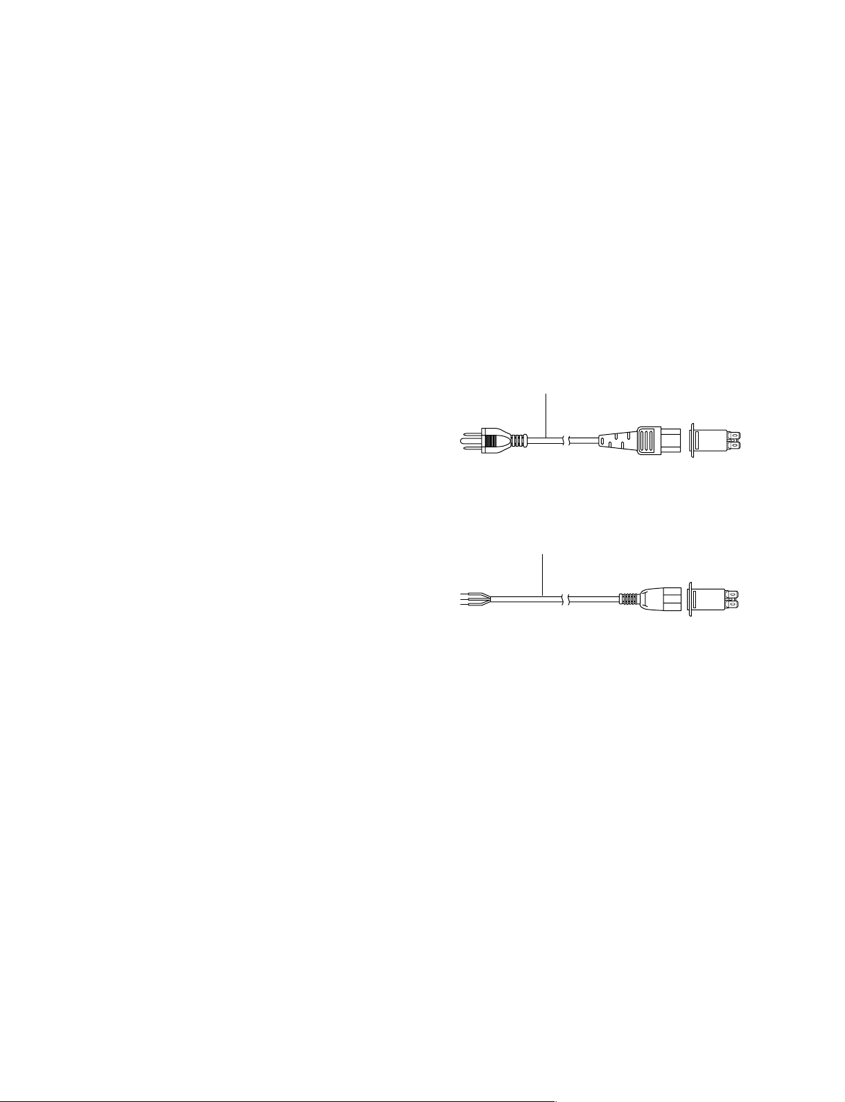
2. Recommended Power Cord
w
. The power cord is not supplied with the BVE-700. Be
sure to use the power cord that is applicable to places in
the area.
To avoid a fire or an electric shock, be sure to use the
designated power cord.
. Do not damage the power cord.
Otherwise, a fire or electric shock may result.
Required Parts for the U.S.A. and Canada
1 Power cord : !1-551-812-11
1
AC inlet
Required Parts for Europe
1 Power cord : !1-782-929-21
1
AC inlet
1-2. Power Supply
1. Power specifications
A switching regulator is used for the power supply of this
unit. The voltage within the range of 100 V to 240 V can
be used without changing the supply voltage.
Power requirements : AC 100 to 240 V ± 10 %
50/60 Hz
Current consumption : Maximum 2.5 A
(with all optional boards installed)
n
As the inrush current at turn-on is the maximum 25 A (at
100 V/50 A (at 200 V), the capacity of the AC power must
be commensurate in it.
If the capacity of the AC power is not the adequately large,
the breaker of the AC power at the supply side will operate
or the unit will abnormally operate.
BVE-700
1-1 (E)
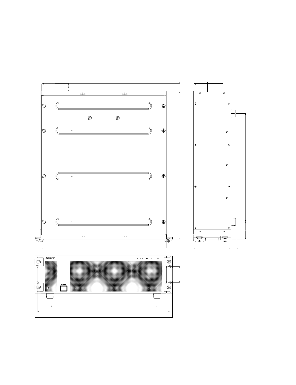
1-3. Installation Space
1-3. Installation Space
Processor unit
26.5
440
375
465
482
520
57.2
132.4
61 380
17.5
Unit : mm
1-2 (E)
BVE-700
 Loading...