

Sony BRC-300, BRC-300P, BRU-300, BRU-300P Service Manual

SERVICE MANUAL
1st Edition (Revised 1)
3CCD COLOR VIDEO CAMERA
BRC-300
BRC-300P
OPTICAL MULTIPLEX UNIT
BRU-300
BRU-300P
ANALOG RGB COMPONENT CARD
BRBK-301
SDI CARD
BRBK-302
OPTICAL MULTIPLEX CARD
BRBK-303
DV CARD
BRBK-304
REMOTE CONTROL UNIT
RM-BR300
BRC-300/300P
BRU-300/300P
! WARNING
This manual is intended for qualified service personnel only.
To reduce the risk of electric shock, fire or injury, do not perform any servicing other than that
contained in the operating instructions unless you are qualified to do so. Refer all servicing to
qualified service personnel.
! WARNUNG
Die Anleitung ist nur für qualifiziertes Fachpersonal bestimmt.
Alle Wartungsarbeiten dürfen nur von qualifiziertem Fachpersonal ausgeführt werden. Um die
Gefahr eines elektrischen Schlages, Feuergefahr und Verletzungen zu vermeiden, sind bei
Wartungsarbeiten strikt die Angaben in der Anleitung zu befolgen. Andere als die angegeben
Wartungsarbeiten dürfen nur von Personen ausgeführt werden, die eine spezielle Befähigung
dazu besitzen.
! AVERTISSEMENT
Ce manual est destiné uniquement aux personnes compétentes en charge de l’entretien. Afin
de réduire les risques de décharge électrique, d’incendie ou de blessure n’effectuer que les
réparations indiquées dans le mode d’emploi à moins d’être qualifié pour en effectuer d’autres.
Pour toute réparation faire appel à une personne compétente uniquement.
BRC-300/300P
RM-BR300
WARNING
This unit has no AC power switch.
When installing the unit, incorporate a readily
accessible disconnect device in the fixed wiring, or
connect the power cord to a socket-outlet which must be
provided near the unit and easily accessible, so that the
user can turn off the power in case a fault should occur.
WARNUNG
Dieses Gerät hat keinen Wechselstromschalter.
Beim Einbau des Geräts ist daher im Festkabel ein
leicht zugänglicher Unterbrecher einzufügen, oder das
Netzkabel mu
ß
mit einer in der Nähe des Geräts
befindlichen, leicht zugänglichen Wandsteckdose
verbunden werden, damit sich bei einer
Funktionsstörung die Stromversorgung zum Gerät
jederzeit unterbrechen lä
ß
t.

BRC-300/300P
BRU-300/300P
1
Table of Contents
Manual Structure
Purpose of this manual .............................................................................................. 7
Related manuals......................................................................................................... 7
Trademarks ................................................................................................................ 8
Contents ..................................................................................................................... 9
1. Service Overview
1-1. Location of Circuit Boards.......................................................................... 1-1
1-1-1. BRC-300 .................................................................................... 1-1
1-1-2. BRU-300 ....................................................................................1-1
1-1-3. RM-BR300 .................................................................................1-1
1-2. Unleaded Solder ..........................................................................................1-2
1-3. Removing/Reattaching the Cabinets (BRC-300/300P)...............................1-2
1-3-1. Side Rear Assembly and Side Front Assembly..........................1-2
1-3-2. Camera Cabinet Upper Assembly ..............................................1-3
1-3-3. Camera Cabinet Lower .............................................................. 1-4
1-3-4. Base Plate ...................................................................................1-5
1-3-5. Blank Panel ................................................................................1-6
1-4. Removing/Reattaching the Outer Panels (BRU-300/300P) ........................1-6
1-4-1. Cover Panel ................................................................................ 1-6
1-4-2. Blank Panel ................................................................................1-7
1-5. Removing/Reattaching the Outer Assembly (RM-BR300) ........................1-7
1-5-1. Outer (Upper) Assembly ............................................................1-7
1-6. Writing the Firmware ..................................................................................1-8
1-6-1. Firmware Writing Program ........................................................1-8
1-6-2. BRC-300/300P ......................................................................... 1-11
1-6-3. BRU-300/300P .........................................................................1-14
1-6-4. RM-BR300 ...............................................................................1-15
1-7. Switch Settings on Boards ........................................................................1-16
1-7-1. BRC-300/300P ......................................................................... 1-16
1-7-2. BRU-300/300P .........................................................................1-18
1-7-3. RM-BR300 ...............................................................................1-21
1-7-4. BRBK-302................................................................................1-22
1-7-5. BRBK-304................................................................................1-22
1-8. Circuit Protection Parts (Fuse) ..................................................................1-23
1-9. Connectors and Cables ..............................................................................1-24
1-10. Signal Inputs and Outputs .........................................................................1-25

BRC-300/300P
BRU-300/300P
2
1-11. Service Action After Board Replacement/Repair .....................................1-27
1-11-1. BRC-300/300P ......................................................................... 1-27
1-11-2. BRU-300/300P .........................................................................1-27
1-11-3. RM-BR300 ...............................................................................1-27
1-11-4. BRBK-301................................................................................1-27
1-11-5. BRBK-302................................................................................1-28
1-11-6. BRBK-303................................................................................1-28
1-11-7. BRBK-304................................................................................1-28
2. Replacement of Main Parts
2-1. BRC-300/300P Main Parts..........................................................................2-1
2-1-1. Camera Assembly ......................................................................2-1
2-1-2. Prism Assembly and CD-389S Board ........................................2-3
2-1-3. Video Lens .................................................................................2-5
2-1-4. CN Chassis Assembly ................................................................2-6
2-1-5. Worm Gear Assembly (Tilt) ......................................................2-7
2-1-6. Tilt Motor ...................................................................................2-8
2-1-7. Worm Gear Assembly (Pan) ...................................................... 2-9
2-1-8. Pan Motor .................................................................................2-10
2-1-9. Combined Flexible Flat Cable ................................................. 2-11
2-2. BRC-300/300P PC Boards ........................................................................2-12
2-2-1. CC-91 Board ............................................................................2-12
2-2-2. CN-2547 Board ........................................................................ 2-13
2-2-3. DC-130 Board .......................................................................... 2-14
2-2-4. DD-208 Board ..........................................................................2-14
2-2-5. DR-526 Board .......................................................................... 2-15
2-2-6. IF-110 Board ............................................................................ 2-15
2-2-7. IF-944 Board and VC-343 Board............................................. 2-16
2-2-8. LED-418 Board ........................................................................2-18
2-2-9. SE-758 Board ...........................................................................2-18
2-2-10. SW-1204 Board........................................................................ 2-19
2-2-11. SY-314 Board...........................................................................2-20
2-3. BRU-300/300P Main Parts ....................................................................... 2-21
2-3-1. Switching Power Unit ..............................................................2-21
2-4. BRU-300/300P Boards..............................................................................2-22
2-4-1. CN-2548 Board ........................................................................ 2-22
2-4-2. LE-281 Board ...........................................................................2-23
2-4-3. MC-66 Board and SW-120 Board............................................2-24
2-5. RM-BR300 Main Parts .............................................................................2-25
2-5-1. Joystick Controller ...................................................................2-25
2-6. RM-BR300 PC Boards..............................................................................2-25
2-6-1. MD-131 Board .........................................................................2-25
2-6-2. SW-1205 Board........................................................................ 2-26

BRC-300/300P
BRU-300/300P
3
3. Electrical Alignment
3-1. Overview .....................................................................................................3-1
3-1-1. Tools/Equipment ........................................................................3-1
3-1-2. Menu .......................................................................................... 3-1
3-2. BRC-300/300P Camera Block Electrical Alignment..................................3-2
3-2-1. Tools/Equipment ........................................................................3-2
3-2-2. Connection for Adjustment ........................................................3-5
3-2-3. Control Software Adjustment .................................................... 3-6
3-2-4. Precaution................................................................................... 3-7
3-2-5. Adjusting Remote Commander.................................................. 3-8
3-2-6. Data Processing ..........................................................................3-9
3-2-7. Data Initialization of Pages 8, A, C, D, E, F, 1E, 1F ...............3-10
3-2-8. 66 MHz/54 MHz Origin Oscillation Adjustment.....................3-20
3-2-9. Video System Adjustments ......................................................3-20
3-2-10. Hall Adjustment .......................................................................3-22
3-2-11. MR Adjustment ........................................................................3-23
3-2-12. Flange Back Adjustment ..........................................................3-24
3-2-13. Picture Frame Setting ...............................................................3-26
3-2-14. Auto White Balance Reference Data Setting ...........................3-27
3-2-15. MAX GAIN Adjustment ..........................................................3-27
3-2-16. F No. & ND Light Quantity Compensation .............................3-28
3-2-17. LV Reference Data Setting ......................................................3-28
3-2-18. Auto White Balance Adjustment ............................................. 3-29
3-2-19. Color Reproduction Adjustment ..............................................3-29
3-2-20. White Balance Check ...............................................................3-31
3-3. BRC-300/300P Video Output System Adjustment................................... 3-32
3-3-1. Tools/Equipment ......................................................................3-32
3-3-2. Connection Diagram ................................................................3-32
3-3-3. Internal Color-Bar Adjustment ................................................ 3-32
3-3-4. SC Frequency Adjustment .......................................................3-33
3-4. BRU-300/300P Electrical Alignment .......................................................3-33
3-4-1. Tools/Equipment ......................................................................3-33
3-4-2. Connection Diagram ................................................................3-33
3-4-3. VCO Free-Running Frequency Adjustment.............................3-34
3-4-4. Encoder Output Level Adjustment...........................................3-34
3-5. BRBK-301 Electrical Alignment ..............................................................3-35
3-5-1. Tools/Equipment ......................................................................3-35
3-5-2. Connection Diagram ................................................................3-35
3-5-3. RGB Component Video Output System Adjustment...............3-36
3-5-4. YCbCr Composite Video Output System Adjustment.............3-38
3-6. BRBK-302 Electrical Alignment ..............................................................3-40
3-6-1. Tools/Equipment ......................................................................3-40
3-6-2. Connection Diagram ................................................................3-40
3-6-3. VCO Free-running Frequency Adjustment ..............................3-41
3-6-4. Output Video Check................................................................. 3-42

BRC-300/300P
BRU-300/300P
4
3-7. BRBK-303 Output Video Check .............................................................. 3-43
3-7-1. Tools/Equipment ......................................................................3-43
3-7-2. Output Video Check................................................................. 3-43
3-8. BRBK-304 Output Video Check .............................................................. 3-44
3-8-1. Tools/Equipment ......................................................................3-44
3-8-2. Output Video Check................................................................. 3-44
4. Troubleshooting
4-1. Overview .....................................................................................................4-1
4-2. BRC-300/300P ............................................................................................4-2
4-2-1. Troubles during Power-on Process of the Unit ..........................4-2
4-2-2. Image System Troubles ..............................................................4-7
4-2-3. Communication Troubles .........................................................4-10
4-2-4. Troubles when Connecting Optional Cards ............................. 4-13
4-3. BRC-300 Camera Block ........................................................................... 4-15
4-4. BRU-300/300P ..........................................................................................4-17
4-4-1. Trouble when Power-on the Unit .............................................4-17
4-4-2. Image System Trouble .............................................................4-19
4-4-3. Communication Trouble ..........................................................4-21
4-4-4. Trouble when Connecting the Optional Card ..........................4-22
4-5. RM-BR300 ................................................................................................4-23
4-5-1. Trouble when Power-on the Unit .............................................4-23
4-5-2. Communication Trouble ..........................................................4-24
4-6. Optional Cards .......................................................................................... 4-26
4-6-1. BRBK-301................................................................................4-26
4-6-2. BRBK-302................................................................................4-30
4-6-3. BRBK-303................................................................................4-32
4-6-4. BRBK-304................................................................................4-34
5. Circuit Description
5-1. BRC-300/300P Circuit Description ............................................................5-1
5-1-1. Camera Block .............................................................................5-1
5-1-2. IF-944 Board .............................................................................. 5-1
5-1-3. CC-91 Board ..............................................................................5-2
5-1-4. SY-314 Board/SW-1204 Board .................................................5-3
5-1-5. CN-2547 Board .......................................................................... 5-3
5-2. BRU-300/300P Circuit Description ............................................................5-4
5-2-1. MC-66 Board ............................................................................. 5-4
5-2-2. CN-2548 Board .......................................................................... 5-5
5-3. RM-BR300 Circuit Description ..................................................................5-5
5-4. BRBK-301 (AN-22 Board) Circuit Description ......................................... 5-6
5-5. BRBK-302 (SD-50 Board) Circuit Description ..........................................5-6
5-6. BRBK-303 (MX-107 Board) Circuit Description.......................................5-7
5-7. BRBK-304 (DV-33 Board) Circuit Description ......................................... 5-7

BRC-300/300P
BRU-300/300P
5
6. Spare Parts
6-1. Notes on Repair Parts.................................................................................. 6-1
6-2. Exploded Views .......................................................................................... 6-2
6-3. Electrical Parts List ................................................................................... 6-10
6-3-1. BRC-300/300P ......................................................................... 6-10
6-3-2. BRU-300/300P .........................................................................6-22
6-3-3. RM-BR300 ...............................................................................6-30
6-3-4. BRBK Series ............................................................................ 6-36
6-4. Supplied Accessories ................................................................................6-48
7. Semiconductor Pin Assignments
8. Block Diagrams
BRC-300/300P Overall ...............................................................................8-1
BRU-300/300P Overall ...............................................................................8-4
RM-BR300 Overall .....................................................................................8-5
BRBK-301 AN-22 ......................................................................................8-6
BRBK-302 SD-50 .......................................................................................8-7
BRBK-303 MX-107.................................................................................... 8-7
BRBK-304 DV-33 ......................................................................................8-8
9. Schematic Diagrams
AN-22 (BRBK-301).................................................................................... 9-2
CC-91 (BRC-300/300P).............................................................................. 9-4
CN-2547 (BRC-300/300P)..........................................................................9-8
CN-2548 (BRU-300/300P) .........................................................................9-9
DR-526 (BRC-300/300P)..........................................................................9-10
DV-33 (BRBK-304).................................................................................. 9-11
IF-944 (BRC-300/300P)............................................................................9-17
MC-66 (BRU-300/300P)...........................................................................9-19
MD-131 (RM-BR300) ..............................................................................9-26
MX-107 (BRBK-303) ...............................................................................9-28
SD-50 (BRBK-302) ..................................................................................9-29
SW-1204 (BRC-300/300P) .......................................................................9-31
SW-1205 (RM-BR300) .............................................................................9-32
SY-314 (BRC-300/300P) ..........................................................................9-34

BRC-300/300P
BRU-300/300P
6
BRC-300/300P Frame Wiring...................................................................9-38
CN-2680..................................................................................................9-38
DD-208 ..................................................................................................9-38
IF-110 ..................................................................................................9-38
LED-418 .................................................................................................9-38
VC-343 .................................................................................................. 9-38
DC-130 .................................................................................................. 9-39
SE-758 ..................................................................................................9-39
BRU-300/300P Frame Wiring ..................................................................9-40
LE-281 .................................................................................................. 9-40
SW-1207 ................................................................................................. 9-40
RM-BR300 Frame Wiring ........................................................................9-41
10. Board Layouts
CC-91 (BRC-300/300P)............................................................................ 10-2
CN-2547 (BRC-300/300P)........................................................................10-4
DC-130 (BRC-300/300P)..........................................................................10-4
LED-418 (BRC-300/300P) .......................................................................10-4
SE-758 (BRC-300/300P) ..........................................................................10-4
DR-526 (BRC-300/300P)..........................................................................10-5
IF-944 (BRC-300/300P)............................................................................10-5
SY-314 (BRC-300/300P) ..........................................................................10-6
SW-1204 (BRC-300/300P) ....................................................................... 10-8
MC-66 (BRU-300/300P)...........................................................................10-9
CN-2548 (BRU-300/300P) .....................................................................10-12
LE-281 (BRU-300/300P) ........................................................................10-13
SW-1207 (BRU-300/300P) .....................................................................10-13
MD-131 (RM-BR300) ............................................................................10-14
SW-1205 (RM-BR300) ...........................................................................10-16
AN-22 (BRBK-301)................................................................................ 10-18
SD-50 (BRBK-302) ................................................................................10-20
MX-107 (BRBK-303) .............................................................................10-22
DV-33 (BRBK-304)................................................................................ 10-24

7
BRC-300/300P
BRU-300/300P
Manual Structure
Purpose of this manual
This manual is the Service manual of the following models.
3CCD Color Video Camera BRC-300/300P
Optical Multiplex Unit BRU-300/300P
Analog RGB Component Card BRBK-301
SDI Card BRBK-302
Optical Multiplex Card BRBK-303
DV Card BRBK-304
Remote Control Unit RM-BR300
This manual is intended for use by trained system and service engineers, and
provides the information of maintenance and detailed service (parts replacement,
guideline for adjustment, schematic diagrams, board layouts, detailed parts list).
Related manuals
Besides this “Service manual”, the following manuals are available.
..
..
. BRC-300/300P Operating Instructions
(Supplied with the BRC-300/300P.)
This manual is necessary for application and operation (and installation) of BRC300/300P.
Part number: 3-854-212-1X (English)
3-854-212-2X (French)
3-854-212-3X (Spanish)
3-854-212-4X (German: BRC-300P only)
..
..
. BRU-300/300P Operating Instructions
(Supplied with the BRU-300/300P.)
This manual is necessary for application and operation (and installation) of BRU300/300P.
Part number: 3-854-214-0X
..
..
. BRBK-301 Operating Instructions (Supplied with the BRBK-301.)
This manual explains the notes for use and specifications of the BRBK-301.
Part number: 3-854-216-0X
..
..
. BRBK-302 Operating Instructions (Supplied with the BRBK-302.)
This manual explains the notes for use and specifications of the BRBK-302.
Part number: 3-854-217-0X
..
..
. BRBK-303 Operating Instructions (Supplied with the BRBK-303.)
This manual explains the notes for use and specifications of the BRBK-303.
Part number: 3-854-218-0X
..
..
. BRBK-304 Operating Instructions (Supplied with the BRBK-304.)
This manual explains the notes for use and specifications of the BRBK-304.
Part number: 3-857-257-0X

8
BRC-300/300P
BRU-300/300P
..
..
. RM-BR300 Operating Instructions (Supplied with the RM-BR300.)
This manual is necessary for application and operation (and installation) of RMBR300.
Part number: 3-854-213-1X
..
..
. “Semiconductor Pin Assignments” CD-ROM (Available on request)
This “Semiconductor Pin Assignments” CD-ROM allows you to search for
semiconductors used in this unit.
Semiconductors that cannot be searched for on this CD-ROM (Latest edition at the
time of issue of this manual.) are listed in the service manual for each unit. The
service manual contains a complete list of all semiconductors and their ID Nos.,
and thus should be used together with the CD-ROM.
Part number: 9-968-546-XX
Trademarks
Trademarks and registered trademarks used in this manual are as follows.
. MS-DOS, Windows and Windows NT are the registered trademark of Microsoft
Corporation in the United States and other countries.
. VISCA is a trademark of Sony Corporation.
Other system names, product names, and company names appearing in this manual
are trademarks or registered trademarks of their respective holders.

9
BRC-300/300P
BRU-300/300P
Contents
This service manual is organized by following sections.
Section 1 Service Overview
Explains the information that is required to service, (the locations of main part,
removal of cabinet, writing the firmware, service action after board replacement/
repair and part replacement, etc.).
Section 2 Replacement of Main Parts
Explains the replacement of mechanical parts, and circuit boards of each unit.
Section 3 Electrical Alignment
Explains the electrical alignment for the maintenance of each unit.
Section 4 Troubleshooting
Explains the measures against trouble.
Section 5 Circuit Description
Explains the circuit operation of the circuit boards installed in each unit.
Section 6 Spare Parts
Describes the exploded views, the mechanical parts list, and the electrical parts list.
Section 7 Semiconductor Pin Assignments
This section contains information on semiconductors used for each unit.
It includes a complete list of the semiconductors and their ID Nos. for retrieving
information on “Semiconductor Pin Assignments” CD-ROM, which is available
separately.
Please refer to this section together with the “Semiconductor Pin Assignments” CDROM.
Information on the semiconductors not contained in the latest CD-ROM at the time
of issue of this manual, if any, is given in this section as well.
Section 8 Block Diagrams
Describes the overall block diagrams of each unit.
Section 9 Schematic Diagrams
Describes the schematic diagrams of the circuit boards installed in each unit and
frame wiring for each unit.
Section 10 Board Layouts
Describes the board layouts of the circuit boards installed in each unit.

1-1
BRC-300/300P
BRU-300/300P
Section 1
Service Overview
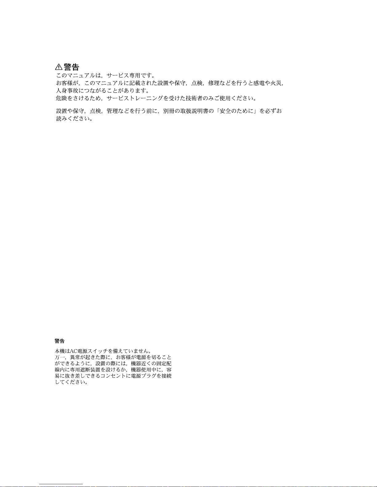
1-1. Location of Circuit Boards
1-1-1. BRC-300
1-1-2. BRU-300
1-1-3. RM-BR300
IF-110 board
LED-418 board
IF-944 board
DR-526 board
DD-208 board
SE-758 board
VC-343 board
CN-2547 board
DC-130 board
CC-91 board
SW-1204 board
SY-314 board
CN-2548 board
SW-1207 board
MC-66 board
LE-281 board
SW-1205 board
MD-131 board

1-2
BRC-300/300P
BRU-300/300P
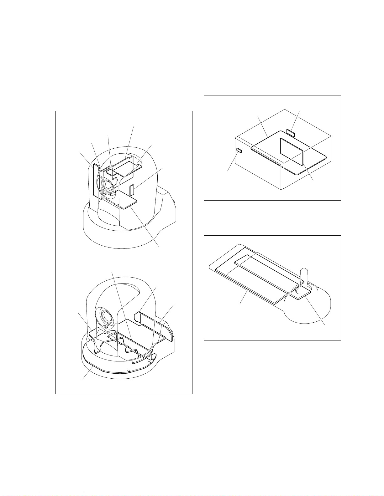
Side rear assembly
M2.6 x 4
Hook
Side front assembly
2
3
1
1-2. Unleaded Solder
Boards requiring use of unleaded solder are printed with a
lead free mark (LF) indicating the solder contains no lead.
(Caution: Some printed circuit boards may not come
printed with the lead free mark due to their particular size.)
: LEAD FREE MARK
m
. Be sure to use the unleaded solder for the printed circuit
board printed with the lead free mark.
. The unleaded solder melts at a temperature about 40 dC
higher than the ordinary solder, therefore, it is recommended to use the soldering iron having a temperature
regulator.
. The ordinary soldering iron can be used but the iron tip
has to be applied to the solder joint for a slightly longer
time. The printed pattern (copper foil) may peel away if
the heated tip is applied for too long, so be careful.
1-3. Removing/Reattaching the Cabinets
(BRC-300/300P)
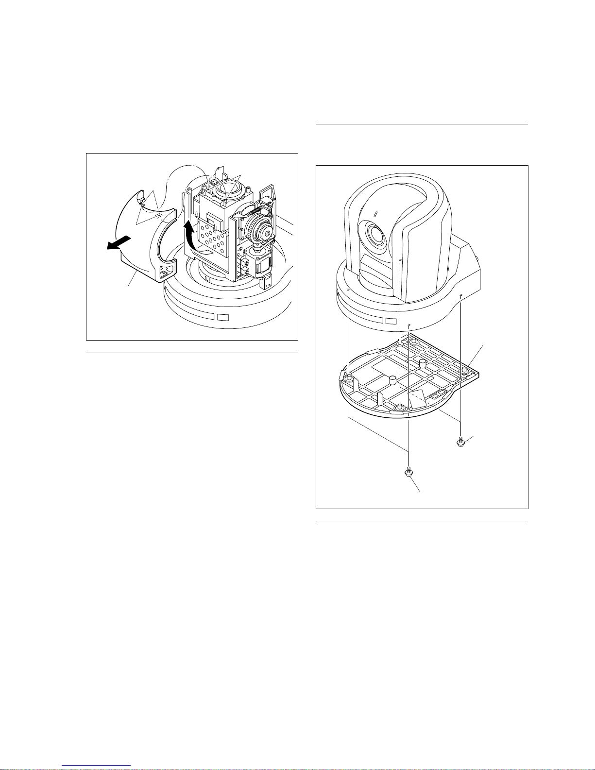
1-3-1. Side Rear Assembly and Side Front
Assembly
Removal
1. Turn the lens roughly backward in the PAN direction,
before removing the side rear assembly as follows.
(1) Remove the screw.
(2) Push the side front assembly in the direction of the
arrow 1 to release the hook of the side rear
assembly.
(3) Move the side rear assembly in the direction of the
arrow 2, and remove it in the direction of the
arrow 3.
1-3
BRC-300/300P
BRU-300/300P
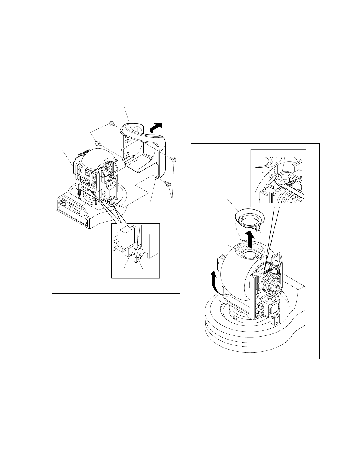
PSW
2.6 x 6
PSW2.6 x 6
Side front assembly
Hook
Pin
Hole
Tilt chassis
2. Return the lens forward, and remove the four screws.
3. Release the two hooks of the side rear assembly from
the pins of the tilt chassis, and remove the side front
assembly.
Installation
4. Reattach the side rear assembly and the side front
assembly in the reverse order of removal.
1-3-2. Camera Cabinet Upper Assembly
Removal
1. Remove the side rear assembly and the side front
assembly. (Refer to steps 1 to 3 in Section 1-3-1.)
2. Turn the lens upward.
3. Release the two hooks of the camera cabinet front
using a flat-head screwdriver as shown in the figure,
and remove the camera cabinet front.
Camera cabinet
front
Lens
Flat-head screwdriver
Hook
1-4
BRC-300/300P
BRU-300/300P
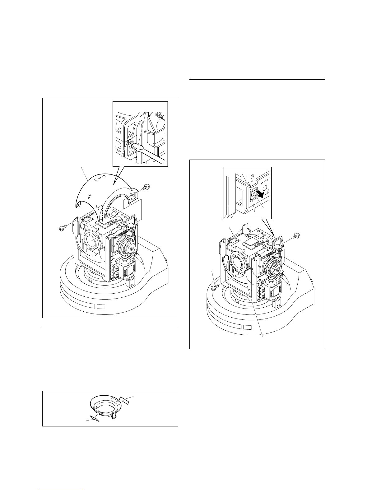
4. Return the lens forward, and remove the two screws.
5. Release the hook of the camera cabinet upper assembly using a flat-head screwdriver as shown in the
figure, and remove the camera cabinet upper assembly.
Installation
6. Reattach the camera cabinet front and camera cabinet
upper assembly in the reverse order from steps 2 to 5.
n
The two tapes A are attached on the camera cabinet
front. When replacing the camera cabinet front, attach
the tapes A to a new camera cabinet front.
7. Reattach the side rear assembly and side front assembly. (Refer to step 4 in Section 1-3-1.)
1-3-3. Camera Cabinet Lower
Removal
1. Remove the side rear assembly and the side front
assembly. (Refer to steps 1 to 3 in Section 1-3-1.)
2. Remove the camera cabinet upper assembly.
(Refer to steps 2 to 5 in Section 1-3-2.)
3. Remove the two screws, and release the hook of the
camera cabinet lower from the pin of the camera
assembly.
Camera cabinet upper
assembly
BTP2 x 6
PSW2 x 6
Flat-head screwdriver
Hook
BTP2 x 6
PSW2 x 6
Camera assembly
Camera cabinet lower
Hook
Pin
Hole
Tape A
Tape A
1-5
BRC-300/300P
BRU-300/300P
Base plate
PSW2.6 x 6
PSW2.6 x 6
1-3-4. Base Plate
Removal
1. Remove the four screws, and remove the base plate.
Installation
2. Reattach the base plate, then secure it with the four
screws.
4. Turn the lens upward.
5. Release the two hooks of the camera cabinet lower
from the pins of the camera assembly, and remove the
camera cabinet lower.
Installation
6. Reattach the camera cabinet lower in the reverse order
from steps 3 to 5.
7. Reassemble the unit in the reverse order from steps 1
and 2.
Hooks
Holes
Pins
Camera cabinet lower

1-6
BRC-300/300P
BRU-300/300P
Blank panel
Screws with stopper
Optional board
Board rails
Screws with stopper
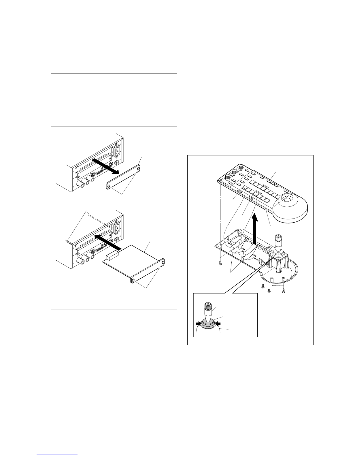
1-3-5. Blank Panel
Removal
1. Loosen the two screws with stopper, and remove the
blank panel.
When the optional board is installed, loosen the two
screws with stopper by hand, and pull out the optional
board slowly.
Installation
2. Reattach the blank panel, and secure it with the two
screws with stopper.
When reinstalling the optional board, insert the board
along the board rails slowly, and secure it with the two
screws with stopper.
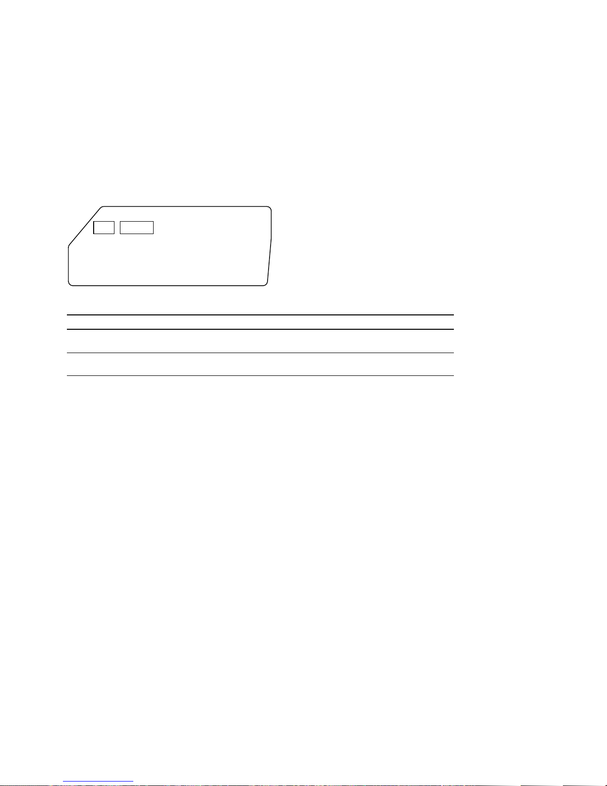
1-4. Removing/Reattaching the Outer
Panels (BRU-300/300P)
1-4-1. Cover Panel
Removal
1. Remove the four screws.
2. Remove the cover panel in the direction of the arrow
while opening its right- and left-side panels.
Installation
3. Reattach the cover panel in the reverse order of
removal.
M3 x 6
M3 x 6
Cover panel
1-7
BRC-300/300P
BRU-300/300P
Blank panel
Optional board
Screws with stopper
Screws with stopper
Board rails
1-4-2. Blank Panel
Removal
1. Loosen the two screws with stopper, and remove the
blank panel.
When the optional board is installed, loosen the two
screws with stopper by hand, and pull out the optional
board slowly.
Installation
2. Reattach the blank panel, and secure it with the two
screws with stopper.
When reinstalling the optional board, insert the board
along the board rails slowly, and secure it with the two
screws with stopper.
1-5. Removing/Reattaching the Outer
Assembly (RM-BR300)
1-5-1. Outer (Upper) Assembly
Removal
1. Remove the seven screws.
2. Remove the outer (upper) assembly upward while
gently pushing the rubber part on the joystick controller in the directions of the arrows.
3. Disconnect the flexible flat cables from the connectors
(CN5001, CN5002) on the SW-1205 board.
Installation
4. Reattach the outer (upper) assembly in the reverse
order from steps 1 to 3.
B3 x 8
CN5001
Outer (upper)
assembly
SW-1205 board
CN5002
B3 x 8
B3 x 8
B3 x 5
Outer (upper)
assembly
Rubber
Joystick controller
Flexible flat cable
1-8
BRC-300/300P
BRU-300/300P
1-6. Writing the Firmware
1-6-1. Firmware Writing Program
Firmware is written into this unit using the writing program installed on a PC (Personal computer).
To write the firmware, install and set it referring to the
following procedure.
Equipment/Program
. PC (Personal computer)
OS: Windows NT 4.0, or Windows 98SE/Me/2000/XP
. Firmware writing program
n
This program is the evaluation version of Flash Development Toolkit.
Download the program from the following URL (website of an MPU manufacturer).
Follow the instructions on the website to download the
program.
This URL is as of May, 2004.
http://www.eu.renesas.com/products/mpumcu/tool/
cgi_bin/fdtreq.cgi
Installation Procedure
1. Double-click the downloaded file.
2. Until the message “Additional Information (Application)” is displayed on the window, repeat that click
[Next|>] button while checking the contents which
appeared on the window.
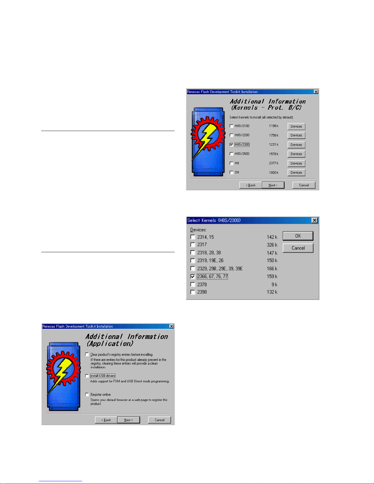
3. Clear the checkbox for “Install USB drivers”, and
click [Next|>] button.
4. Clear all the checkboxes except “H8S/2300”, and click
[Devices] button on the right of “H8S/2300”.
The Select Kernels (H8S/2300) window appears.
5. Clear all the checkboxes except “2366, 67, 76, 77”,
and click [OK] button.
1-9
BRC-300/300P
BRU-300/300P
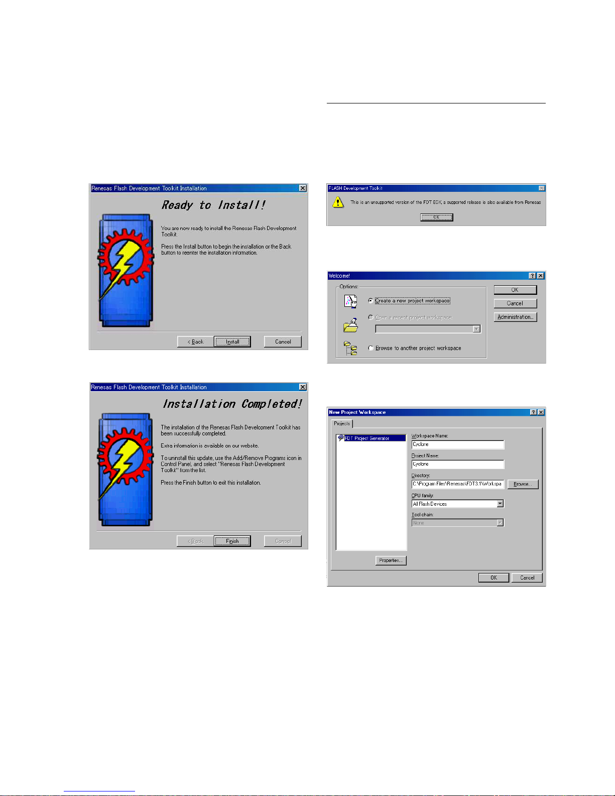
6. Until the “Read to Install!” displayed on the window,
repeat that click [Next|>] button while checking the
contents which appeared on the window.
7. Click [Install] button.
After the installation, the message “Installation
Completed!” appears on the window.
8. Click [Finish] button.
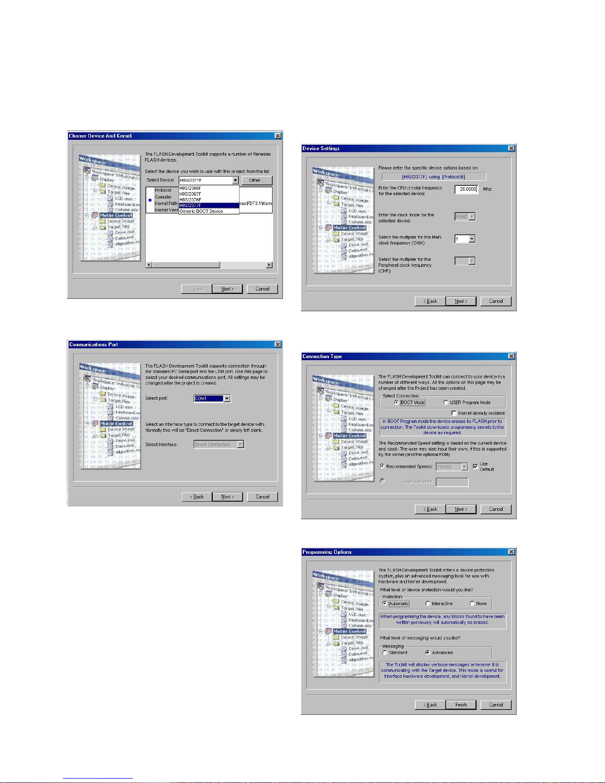
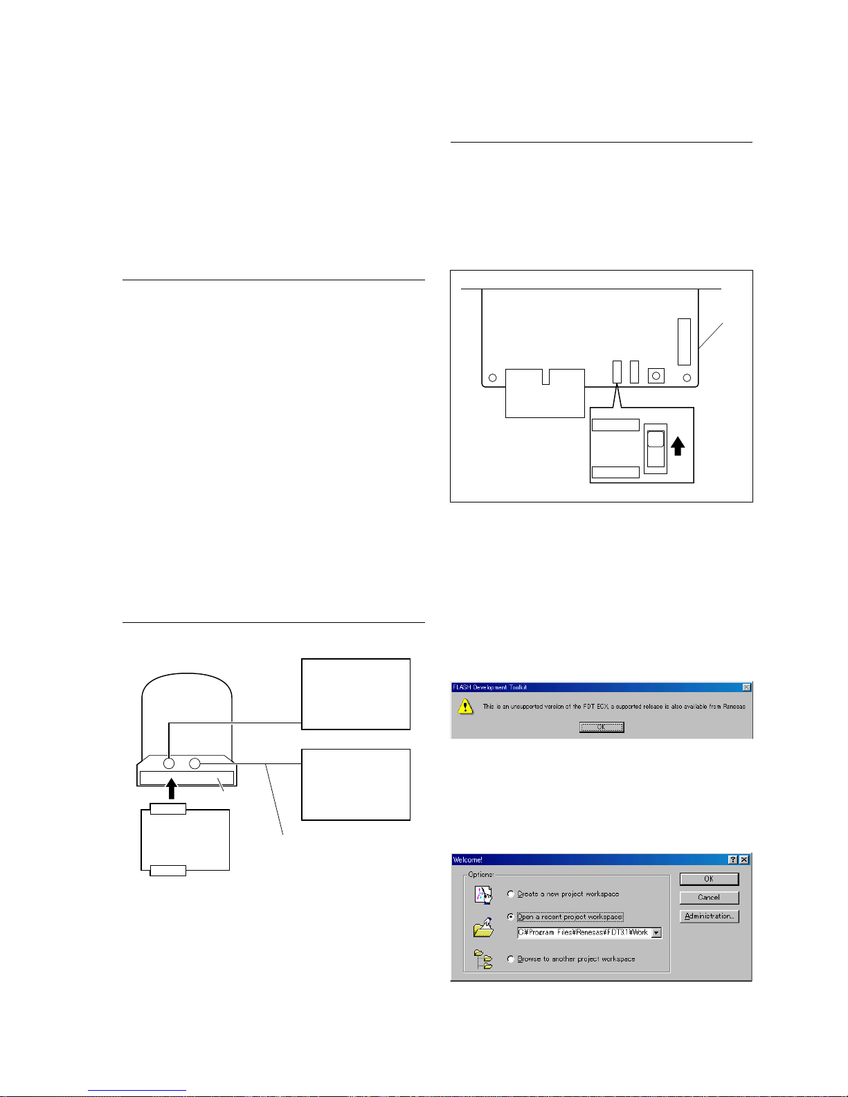
Setup
1. Start the installed firmware writing program.
The warning window appears.
2. Click [OK] button on the warning window to display
the Welcome! window.
3. Check the checkbox of “Create a new workspace”, and
click [OK] button.
4. Enter “Cyclone” into the text box of “Workspace
Name:”, and click [OK] button.
1-10
BRC-300/300P
BRU-300/300P
5. Select “H8S/2377F” in “Select Device:”, and click
[Next|>] button.
6. Select a port in “Select port:”, and click [Next|>]
button.
7. Enter “25.0000” into the text box of “Enter the CPU
crystal frequency for the selected device:”, and click
[Next|>] button.
8. Select “BOOT Mode” in “Select Connection:”, and
click [Next|>] button.
9. Click [Finish] button.
1-11
BRC-300/300P
BRU-300/300P
EX-947
board
S003
WRITE
NORMAL
S003
S001
BRC-300
EX-947
Card slot
CN001
75 Z
VISCA
RS-232C
IN
VIDEO
OUT
VISCA RS-232C cable
PC
RS-232C
IN
Color monitor
1-6-2. BRC-300/300P
Firmware has not been written in the SY-314 mounted
circuit board or the MPU (IC1019/SY-314 board) specified
as a service part.
After replacing the SY-314 board or the MPU (IC1019/
SY-314 board), write the firmware.
Tools/Equipment
. PC (personal computer)
PC with the firmware writing program installed
(Refer to Section 1-6-1.)
. Color monitor
. VISCA RS-232C cable: 1-590-879-31
n
Supplied with the BRU-300/300P or RM-BR300.
. Extension board EX-947
n
The firmware can be written without the extension
board.
. Firmware file: “cyclone.mot”
n
To get the firmware, contact your local Sony Sales
Office/Service Center.
Connection Diagram
Writing Procedure
1. Remove the blank panel or the optional board.
(Refer to Section 1-3-5.)
2. Connect the equipment and tools, referring to Connection Diagram.
3. Set the switch S003 on the EX-947 board to WRITE.
When the EX-947 board is not connected, remove the
base plate, and set the switch S1003-1 on the SY-314
board to ON. (Refer to Section 1-3-4.)
4. Turn on the power of all the equipment.
5. Perform the following steps 1 to 12 to write the
firmware.
(1) Copy the firmware (cyclone.mot) into the PC.
(2) Start the firmware writing program.
The warning window appears.
(3) Click [OK] button on the warning window to
display the Welcome! window.
(4) Check the checkbox for “Open a recent project
workspace:”, and then select “Cyclone”.
(5) Click [OK] button.
1-12
BRC-300/300P
BRU-300/300P
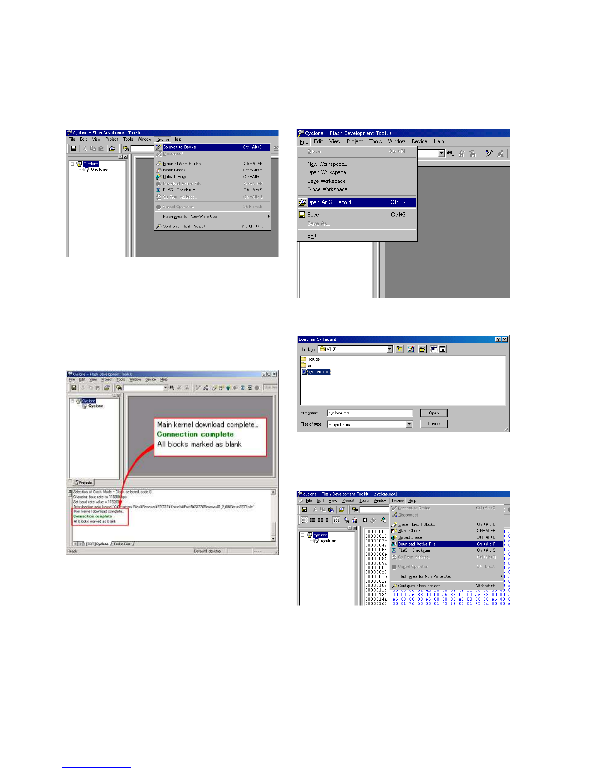
(6) On the toolbar, select “Device” - “Connect to
Device”.
The message “Connection complete” appears on
the Command window of the bottom of the
window.
m
. If the message “Connection failed” appears,
check the connections, power supply, and switch
settings.
. If an error message appears, return to step (2).
(7) On the toolbar, select “File” - “Open An S-
Record...”.
(8) Select the firmware (cyclone.mot), and click
[Open] button.
(9) On the toolbar, select “Device” - “Download
Active File”.
The writing operation starts automatically.

1-13
BRC-300/300P
BRU-300/300P
(12)Check that the message “Disconnected” is dis-
played on the Command window of the bottom of
the window, and exit the firmware writing program.
6. Turn off the power of the BRC-300/300P.
When using the EX-947 board
7. Reset the switch S003 on the EX-947 board to NORMAL.
8. Turn on the power of the BRC-300/300P while
pressing the switch S001 on the EX-947 board.
n
Press the switch until the message “Doing Super
Reset” appears on the color monitor.
When not using the EX-947 board
7. Reset the switch S1003-1 on the SY-314 board to
OFF.
8. Turn on the power of the BRC-300/300P while
pressing the switch S1004 on the SY-314 board.
n
Press the switch until the message “Doing Super
Reset” appears on the color monitor.
9. Check that the message “End of Super Reset Please
Restart” is displayed, and turn off the power of all the
equipment.
10. Perform “3-3. BRC-300/300P Video Output System
Adjustment”.
(10)When the writing operation is completed, the
message “Image successfully written to device”
appears on the Command window of the bottom of
the window.
(11)On the toolbar, select “Device” - “Disconnect”.
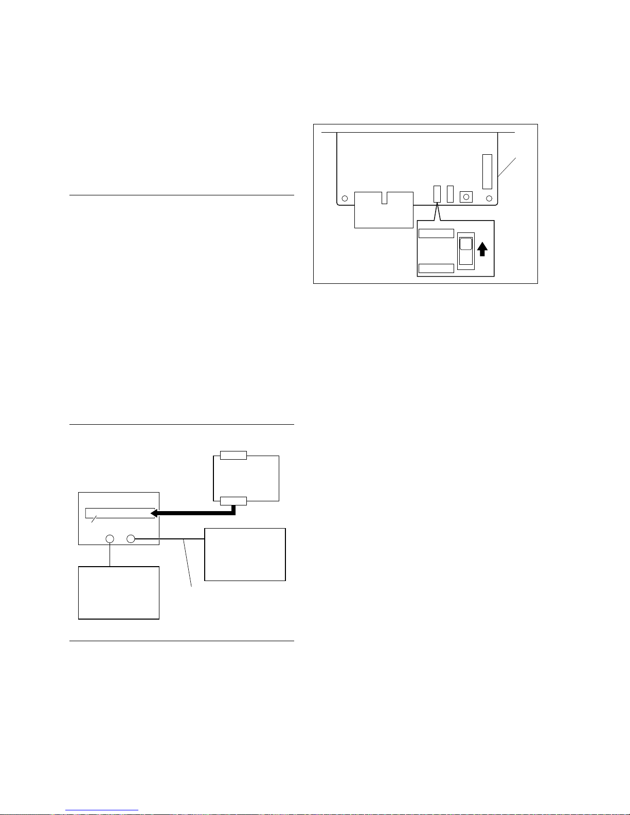
1-14
BRC-300/300P
BRU-300/300P
EX-947
board
S003
WRITE
NORMAL
S003
S001
BRU-300
IN
Color monitor
Card slot
VISCA RS-232C
IN
VISCA RS-232C cable
PC
RS-232C
75 Z
VIDEO
OUT
EX-947
CN001
3. Set the switch S003 on the EX-947 board to WRITE.
When the EX-947 board is not connected, remove the
cover panel, and set the switch S3501-1 on the MC-66
board to ON. (Refer to Section 1-4-1.)
4. Turn on the power of all the equipment.
5. Write the firmware, referring to step 5 in Section 1-6-
2.
n
Selecting firmware file is “Cyclone_MIU.mot”.
6. Turn off the power switch of the BRU-300/300P.
When using the EX-947 board
7. Reset the switch S003 on the EX-947 board to NORMAL.
8. Turn on the power switch of the BRU-300/300P while
pressing the switch S001 on the EX-947 board.
n
Press the switch until the message “Doing Super
Reset” appears on the color monitor.
When not using the EX-947 board
7. Reset the switch S3501-1 on the MC-66 board to OFF.
8. Turn on the power switch of the BRU-300/300P while
pressing the switch S4801 on the CN-2548 board.
n
Press the switch until the message “Doing Super
Reset” appears on the color monitor.
9. Check that the message “End of Super Reset Please
Restart” is displayed, and turn off the power of all the
equipment.
10. Perform “3-4. BRU-300/300P Electrical Alignment”.
1-6-3. BRU-300/300P
Firmware has not been written in the MC-66 board or the
MPU (IC3518/MC-66 board) specified as a service part.
After replacing the MC-66 board or the MPU (IC3518),
write the firmware.
Tools/Equipment
. PC (personal computer)
PC with the firmware writing program installed
(Refer to Section 1-6-1.)
. Color monitor
. VISCA RS-232C cable (Supplied with this unit)
. Extension board EX-947
n
The firmware can be written without the extension
board.
. Firmware file: “Cyclone_MIU.mot”
n
To get the firmware, contact your local Sony Sales
Office/Service Center.
Connection Diagram
Writing Procedure
1. Remove the blank panel or the optional board.
(Refer to Section 1-4-2.)
2. Connect the equipment and tools, referring to Connection Diagram.
1-15
BRC-300/300P
BRU-300/300P
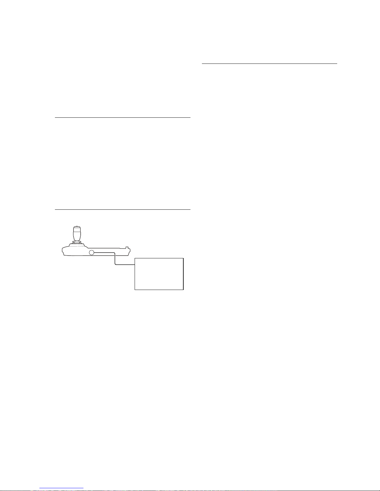
VISCA RS-232C IN
VISCA RS-232C
cable
PC
RS-232C
RM-BR300
1-6-4. RM-BR300
Firmware has not been written in the MC-66 board or the
MPU (IC5004/MD-131 board) specified as a service part.
After replacing the MD-131 board or the MPU (IC5004),
write the firmware.
Equipment/Tools
. PC (Personal computer)
PC with the firmware writing program installed
(Refer to Section 1-6-1.)
. VISCA RS-232C cable (Supplied with this unit)
. Firmware file: “controlier.mot”
n
To get the firmware, please contact your local Sony
Sales Office/Service Center.
Connection Diagram
Writing Procedure
1. Remove the outer (upper) assembly.
(Refer to Section 1-5-1.)
2. Connect the equipment and tools, referring to Connection Diagram.
3. Set the switch S5006-2 on the MD-131 board to ON.
4. Turn on the power of each equipment.
5. Write the firmware, referring to step 5 in Section 1-6-
2.
n
Selecting firmware file is “controller.mot”.
6. Turn off the power switch of the RM-BR300.
7. Reset the switch S5006-2 on the MD-131 board to
OFF.
8. Reattach the outer (upper) assembly.
(Refer to Section 1-5-1.)
9. Turn on the power switch of the RM-BR300.
10. Press the MENU button for two seconds while pressing the RESET, PRESET, and L/R DIRECTION
buttons simultaneously.
11. Check that the blinking speed of the indicator changes,
and turn off the power of each equipment.
1-16
BRC-300/300P
BRU-300/300P
1-7. Switch Settings on Boards
1-7-1. BRC-300/300P
n
Never change the settings of the factory use switches.
SW-1204 Board
Ref. No. Name Description Factory setting
S2201 IR SELECT Selects a camera number when one remote commander 1
is used for multiple cameras.
S2202 75 Z termination switch 75 Z termination ON/OFF switch for the EXT SYNC IN ON
connector
S2201S2202
SW-1204 BOARD (SIDE A)
1-17
BRC-300/300P
BRU-300/300P
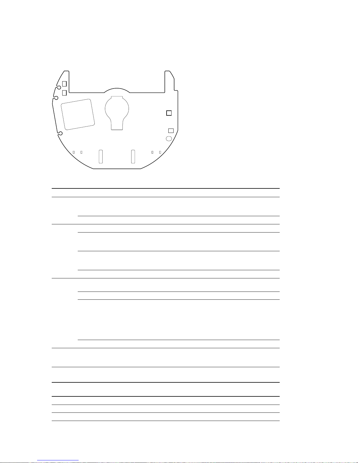
SY-314 Board
Ref. No. Bit Name Description Factory setting
S1001 1 Camera address setting switch Sets a camera address.
*
0 (All OFF)
2
3
4 — Factory use OFF
S1002 1 — Factory use OFF
2 RS-232C/RS-422 Selects RS-232C or RS-422. OFF (RS-232C)
ON: RS-422
OFF: RS-232C
3 9600bps/38400bps Sets communication baud rate. OFF (9600 bps)
ON: 38400 bps
OFF: 9600 bps
4 IR OUT Sets infrared output to ON/OFF. OFF
S1003 1 MYCOM WRITING Set this to ON only when writing the OFF
firmware without the EX-947 board.
2 JTAG SELECT Factory use OFF
3 OPE/ADJ MODE SELECT Switches operation modes. (Normal/ Normal mode
Adjustment) (OFF)
n
Set this to ON only when adjusting
without the EX-947 board.
ON: Adjustment mode
OFF: Normal mode
4 — Factory use OFF
S1004 — SUPER RESET When the power is turned on while this —
switch is pressed, the menu settings and
adjustment values are initialized.
*: Camera address settings
Camera addresses
01234567
S1001-1 OFF ON OFF ON OFF ON OFF ON
S1001-2 OFF OFF ON ON OFF OFF ON ON
S1001-3 OFF OFF OFF OFF ON ON ON ON
S1001
S1002
S1003
S1004
SY-314 BOARD (SIDE B)
1-18
BRC-300/300P
BRU-300/300P
1-7-2. BRU-300/300P
n
Never change the settings of the factory use switches.
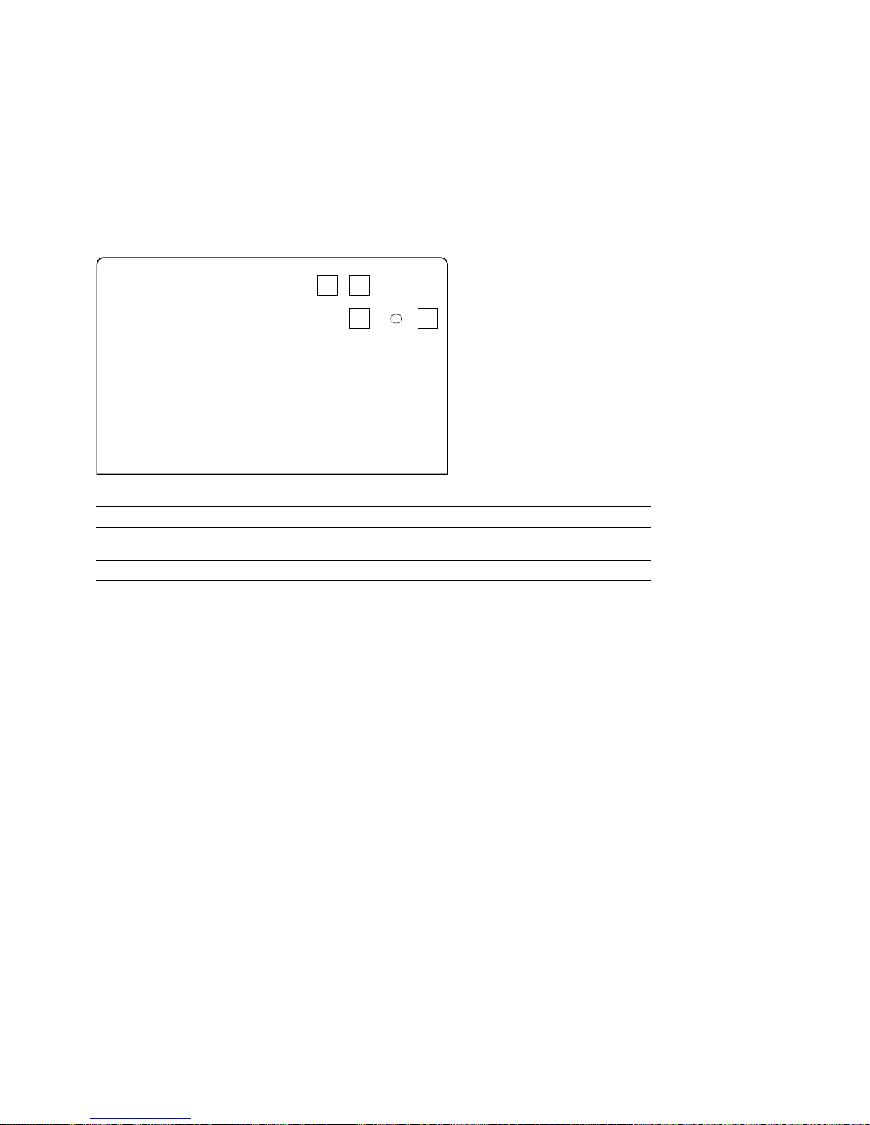
CN-2548 Board
Ref. No. Name Description Factory setting
S4801 FACTORY RESET When the power is turned on while this switch is pressed, —
the menu settings and adjustment values are initialized.
S4802 ADJ NO Selects a menu in the adjustment mode. —
S4803 DATA UP Increments an adjustment value in the adjustment mode. —
S4804 DATA DOWN Decrements an adjustment value in the adjustment mode. —
S4801
S4802
S4803
S4804
CN-2548 BOARD (SIDE A)
 Loading...